EP2857601A1 - Hybrid construction machine - Google Patents
Hybrid construction machine Download PDFInfo
- Publication number
- EP2857601A1 EP2857601A1 EP14181956.5A EP14181956A EP2857601A1 EP 2857601 A1 EP2857601 A1 EP 2857601A1 EP 14181956 A EP14181956 A EP 14181956A EP 2857601 A1 EP2857601 A1 EP 2857601A1
- Authority
- EP
- European Patent Office
- Prior art keywords
- electric
- power
- regenerated
- regeneration
- boom
- Prior art date
- Legal status (The legal status is an assumption and is not a legal conclusion. Google has not performed a legal analysis and makes no representation as to the accuracy of the status listed.)
- Granted
Links
Images


Classifications
-
- E—FIXED CONSTRUCTIONS
- E02—HYDRAULIC ENGINEERING; FOUNDATIONS; SOIL SHIFTING
- E02F—DREDGING; SOIL-SHIFTING
- E02F9/00—Component parts of dredgers or soil-shifting machines, not restricted to one of the kinds covered by groups E02F3/00 - E02F7/00
- E02F9/20—Drives; Control devices
- E02F9/2058—Electric or electro-mechanical or mechanical control devices of vehicle sub-units
- E02F9/2091—Control of energy storage means for electrical energy, e.g. battery or capacitors
-
- B—PERFORMING OPERATIONS; TRANSPORTING
- B60—VEHICLES IN GENERAL
- B60K—ARRANGEMENT OR MOUNTING OF PROPULSION UNITS OR OF TRANSMISSIONS IN VEHICLES; ARRANGEMENT OR MOUNTING OF PLURAL DIVERSE PRIME-MOVERS IN VEHICLES; AUXILIARY DRIVES FOR VEHICLES; INSTRUMENTATION OR DASHBOARDS FOR VEHICLES; ARRANGEMENTS IN CONNECTION WITH COOLING, AIR INTAKE, GAS EXHAUST OR FUEL SUPPLY OF PROPULSION UNITS IN VEHICLES
- B60K6/00—Arrangement or mounting of plural diverse prime-movers for mutual or common propulsion, e.g. hybrid propulsion systems comprising electric motors and internal combustion engines
- B60K6/20—Arrangement or mounting of plural diverse prime-movers for mutual or common propulsion, e.g. hybrid propulsion systems comprising electric motors and internal combustion engines the prime-movers consisting of electric motors and internal combustion engines, e.g. HEVs
- B60K6/22—Arrangement or mounting of plural diverse prime-movers for mutual or common propulsion, e.g. hybrid propulsion systems comprising electric motors and internal combustion engines the prime-movers consisting of electric motors and internal combustion engines, e.g. HEVs characterised by apparatus, components or means specially adapted for HEVs
-
- E—FIXED CONSTRUCTIONS
- E02—HYDRAULIC ENGINEERING; FOUNDATIONS; SOIL SHIFTING
- E02F—DREDGING; SOIL-SHIFTING
- E02F9/00—Component parts of dredgers or soil-shifting machines, not restricted to one of the kinds covered by groups E02F3/00 - E02F7/00
- E02F9/08—Superstructures; Supports for superstructures
- E02F9/10—Supports for movable superstructures mounted on travelling or walking gears or on other superstructures
- E02F9/12—Slewing or traversing gears
- E02F9/121—Turntables, i.e. structure rotatable about 360°
- E02F9/128—Braking systems
-
- E—FIXED CONSTRUCTIONS
- E02—HYDRAULIC ENGINEERING; FOUNDATIONS; SOIL SHIFTING
- E02F—DREDGING; SOIL-SHIFTING
- E02F9/00—Component parts of dredgers or soil-shifting machines, not restricted to one of the kinds covered by groups E02F3/00 - E02F7/00
- E02F9/20—Drives; Control devices
- E02F9/2058—Electric or electro-mechanical or mechanical control devices of vehicle sub-units
- E02F9/2062—Control of propulsion units
- E02F9/2075—Control of propulsion units of the hybrid type
-
- E—FIXED CONSTRUCTIONS
- E02—HYDRAULIC ENGINEERING; FOUNDATIONS; SOIL SHIFTING
- E02F—DREDGING; SOIL-SHIFTING
- E02F9/00—Component parts of dredgers or soil-shifting machines, not restricted to one of the kinds covered by groups E02F3/00 - E02F7/00
- E02F9/20—Drives; Control devices
- E02F9/2058—Electric or electro-mechanical or mechanical control devices of vehicle sub-units
- E02F9/2095—Control of electric, electro-mechanical or mechanical equipment not otherwise provided for, e.g. ventilators, electro-driven fans
-
- E—FIXED CONSTRUCTIONS
- E02—HYDRAULIC ENGINEERING; FOUNDATIONS; SOIL SHIFTING
- E02F—DREDGING; SOIL-SHIFTING
- E02F9/00—Component parts of dredgers or soil-shifting machines, not restricted to one of the kinds covered by groups E02F3/00 - E02F7/00
- E02F9/20—Drives; Control devices
- E02F9/22—Hydraulic or pneumatic drives
- E02F9/2217—Hydraulic or pneumatic drives with energy recovery arrangements, e.g. using accumulators, flywheels
-
- Y—GENERAL TAGGING OF NEW TECHNOLOGICAL DEVELOPMENTS; GENERAL TAGGING OF CROSS-SECTIONAL TECHNOLOGIES SPANNING OVER SEVERAL SECTIONS OF THE IPC; TECHNICAL SUBJECTS COVERED BY FORMER USPC CROSS-REFERENCE ART COLLECTIONS [XRACs] AND DIGESTS
- Y10—TECHNICAL SUBJECTS COVERED BY FORMER USPC
- Y10S—TECHNICAL SUBJECTS COVERED BY FORMER USPC CROSS-REFERENCE ART COLLECTIONS [XRACs] AND DIGESTS
- Y10S903/00—Hybrid electric vehicles, HEVS
- Y10S903/902—Prime movers comprising electrical and internal combustion motors
- Y10S903/903—Prime movers comprising electrical and internal combustion motors having energy storing means, e.g. battery, capacitor
Definitions
- the present invention relates to a hybrid construction machine configured to make a regenerative action through return fluid from a hydraulic actuator such as a boom cylinder.
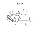
- This excavator comprises: a crawler-type lower traveling body 1; an upper slewing body 2 mounted on the lower traveling body 1 slewably about an axis O perpendicular to a ground surface; an attachment AT attached to the upper slewing body 2; an engine; and a hydraulic pump configured to be driven by the engine.
- the attachment AT includes a boom 3, an arm 4, a bucket 5, and a plurality of hydraulic actuators, namely, a boom cylinder 6, an arm cylinder 7 and a bucket cylinder 8.
- the lower traveling body 1 is configured to be driven by a traveling drive unit using a traveling hydraulic motor as a drive source
- the upper slewing body 2 is configured to be driven by a slewing drive unit using a slewing hydraulic motor as a drive source.
- the attachment AT is configured to be actuated by hydraulic fluid supplied from the hydraulic pump.
- the above excavator is further equipped with a generator motor configured to make a generator action and a motor action, and an electrical storage device, wherein the generator motor and the hydraulic pump are connected to the engine.
- the generator-motor is operable to charge the electrical storage device through the generator action, and to be driven by electric power stored in the electrical storage device, on a timely basis, to make the motor action, thereby assisting the engine.
- the Patent Literature 1 discloses making a slewing regenerative action during a slewing operation in addition to a boom-lowering regenerative action during the boom-lowering operation; more specifically, it is disclosed that, during slewing braking, the electrical storage device is charged with electric power regenerated by a slewing motor acting as a slewing drive source while regenerative braking force is generated.
- Patent Literature 2 There has also been known another type which comprises a slewing drive source composed of a hydraulic motor to which a generator is coupled to make a slewing regenerative action in the same manner as above, as disclosed in JP 2009-127643A (Patent Literature 2).
- a hybrid construction machine which comprises: an engine; a generator-motor configured to make a generator action and a motor action; a hydraulic pump configured to be driven by the engine; a hydraulic actuator configured to be operated by the hydraulic pump as a hydraulic pressure source; an actuator regeneration section configured to make a regenerative action of generating actuator regenerated-electric-power through return fluid from the hydraulic actuator; an electric storage device capable of being charged and discharging electric power stored therein; a charging-rate detector configured to detect a charging rate of the electric storage device; and a control section configured to perform: causing the electric storage device to be charged with electric power generated by the generator-motor making the generator action and the actuator regenerated-electric-power generated by the actuator regeneration section making the regenerative action; causing the generator-motor to make the motor action through the electric power stored in the electric storage device to thereby assist the engine; and a regeneration control of stopping the generator action of the generator-motor and restricting the actuator regenerated-electric-power to be generated by the actuator regeneration section when the
- This embodiment is one example in which the present invention is applied to the hybrid excavator shown in FIG. 7 .
- FIG. 1 shows a substantial part of a hybrid excavator according to this embodiment.
- the hybrid excavator according to this embodiment includes an engine 9, a generator-motor 10, a hydraulic pump 11, an electrical storage device 12, a control section 13 and a slewing motor 14.
- a set of thick solid lines, a set of broken lines and a set of normal solid lines denote a power circuit, a signal circuit and a hydraulic circuit, respectively.
- the generator-motor 10 and the hydraulic pump 11 are connected to the engine 9 in a tandem (or parallel) arrangement to be driven by the engine 9.
- the generator-motor 10 is configured to make a generator action and a motor action.
- the hydraulic pump 11 is configured to be driven by the engine 9 to thereby discharge hydraulic fluid.
- the electrical storage device 12 is constituted of, for example, a nickel-hydrogen battery or a lithium-ion battery, and functions as a power supply.
- the electrical storage device 12 is capable of storing therein electric power, i.e., being charged, and discharging electric power stored therein.
- the electrical storage device 12 is connected to the generator-motor 10.
- the control section 13 is configured to output a control signal to control a discharge action of the electrical storage device 12 according to a charging rate, a generator action of the generator-motor 10 and a motor action of the generator-motor 10. Specifically, the control section 13 is configured to cause the generator-motor 10 to make the generator action and send electric power generated by the generator action to the electrical storage device 12 to thereby charge the electrical storage device 12, when the charging rate of the electrical storage device 12 is lowered, and to cause the generator-motor 10, on a timely basis, to make the motor action through the electric power discharged from the electrical storage device 12 to thereby assist the engine 9.
- the slewing motor 14 is a slewing drive source for slewing the upper slewing body 2 shown in FIG. 7 .
- the slewing motor 14 is connected to the electrical storage device 12 to be rotationally driven by electric power stored in the electrical storage device 12.
- the slewing motor 14 makes the generator action to generate electric power, with which the electrical storage device 12 is charged.
- the control section 13 includes a controller 15, a generator-motor inverter 16, a slewing-motor inverter 17 and a generator inverter 18.
- the generator-motor inverter 16 is configured to control an operation of the generator-motor 10.
- the slewing-motor inverter 17 is configured to control an operation of the slewing motor 14.
- the generator inverter 18 is configured to perform a generator control for below-mentioned boom-lowering regeneration, i.e., for a regeneration during the boom-lowering operation in which the boom 3 shown in FIG. 7 is operated downward.
- the hybrid excavator further comprises a plurality of detectors.
- the plurality of detectors includes a charging-rate detector 19 configured to detect a charging rate of the electrical storage device 12 and a slewing speed detector 20 configured to detect a slewing speed of the upper slewing body 2, i.e., a rotational speed of an output shaft of the slewing motor 14.
- the detectors 19, 20 are configured to generate respective detection signals indicative of the charging rate and the slewing speed, respectively. These detection signals are input into the controller 15.
- the hybrid excavator further comprises a plurality of manipulation devices.
- the plurality of manipulation devices includes a slewing manipulation lever 21 and a boom manipulation lever 22.
- a manipulation for slewing the upper slewing body 2 is applied by an operator.
- the slewing manipulation lever 21 is operable to generate a slewing operation signal, which is an electric signal corresponding to the manipulation applied to the slewing manipulation lever 21, and input the generated slewing operation signal into the controller 15.
- a manipulation for extending or retracting the boom cylinder 6 is applied by an operator.
- the boom manipulation lever 22 is operable to generate a boom operation signal, which is an electric signal corresponding to the manipulation applied to the boom manipulation lever 22, and input the generated boom operation signal into the controller 15.
- the boom manipulation signal includes a below-mentioned boom-lowering operation signal.
- the boom manipulation lever 22 is connected to a non-shown boom remote control valve configured to generate a pilot signal which is a boom-operation hydraulic signal corresponding to the manipulation applied to the boom manipulation lever 22.
- the hybrid excavator further comprises a plurality of control valves provided for the hydraulic actuators respectively.
- the plurality of control valves includes a control valve 23 for the boom cylinder 6.
- the control value 23 is interposed between the hydraulic pump 11 and the boom cylinder 6 and configured to be operated by the pilot signal output from the boom remote control valve to control supply of hydraulic fluid to the boom cylinder 6.
- the extension/retraction drive of the boom cylinder 6 is thereby controlled.
- respective manipulation devices and control valves for other hydraulic actuators namely, the arm cylinder 7 and the bucket cylinder 8 constituting the attachment AT shown in FIG. 7 , the traveling hydraulic motor and others.
- the boom cylinder 6 has an extension-side hydraulic chamber 6a into which hydraulic fluid for actuating the boom cylinder 6 in an extension direction is introduced and a retraction-side hydraulic chamber 6b into which hydraulic fluid for actuating the boom cylinder 6 in a retraction direction is introduced.
- the control value 23 comprises a hydraulic-pilot-controlled selector valve having a neutral position 23a, a boom-lowering position 23b and a boom-raising position 23c, which positions are selected by the pilot signal.
- the control valve 23 is operable: to isolate the boom cylinder 6 from the hydraulic pump 11 when set to the neutral position 23a; to form a fluid path for introducing hydraulic fluid discharged from the hydraulic pump 11 into the retraction-side hydraulic chamber 6b and a fluid path for returning hydraulic fluid flowed out from the extension-side hydraulic chamber 6a to a tank when set to the boom-lowering position 23b; and to form a fluid path for introducing hydraulic fluid discharged from the hydraulic pump 11 into the extension-side hydraulic chamber 6a and a fluid path for returning hydraulic fluid flowed out from the retraction-side hydraulic chamber 6b to the tank when set to the boom-raising position 23c.
- the hybrid excavator according to this embodiment further comprises an actuator regeneration section 30 configured to make a regenerative action through return fluid from the boom cylinder 6 which is one of the hydraulic actuators.
- the principle of the regenerative action is as follows.
- the pressure in the extension-side hydraulic chamber 6a is always raised because the gravity acting on the attachment AT always applies to the boom cylinder 6 a load in a boom-lowering direction, i.e., a direction of retracting the boom cylinder 6. This gives a certain amount of energy to the hydraulic fluid flowed out from the extension-side hydraulic chamber 6a, namely, return fluid, during the boom-lowering operation.
- the actuator regeneration section 30 is configured to make a regenerative action of generating regenerated-electric-power by the energy of the return fluid, i.e., the hydraulic fluid flowed out from the extension-side hydraulic chamber 6a during the boom-lowing operation, thereby recovering the energy as electric power.
- the actuator regeneration section 30 in this embodiment includes a regeneration circuit 24, a regeneration motor 25, a regeneration generator 26, a bypass circuit 28 and a flow regulating valve 29.
- the regeneration circuit 24 forms a flow path of the return fluid from the extension-side hydraulic chamber 6a of the boom cylinder 6 to a tank T.
- the regeneration circuit 24 is provided with a check valve 27 for preventing a back-flow midway thereof.
- the regeneration motor 25 is constituted of a hydraulic motor and provided in the regeneration circuit 24 to be rotationally driven by the energy of the return fluid flowed in the regeneration circuit 24.
- the regeneration generator 26 is connected to the regeneration motor 25 to be driven by the regeneration motor 25 to thereby generate regenerated-electric-power. With the regenerated-electric-power, the electrical storage device 12 can be charged.
- the bypass circuit 28 is connected to the regeneration circuit 24, in parallel to the regeneration motor 25, that is, in such a manner as to bypass the regeneration motor 25.
- the flow regulating valve 29 is provided in the bypass circuit 28 to regulate a flow rate of the hydraulic fluid flowed in the bypass circuit 28.
- the flow regulating valve 29 in this embodiment is constituted of a solenoid valve controllable by an electric signal input thereto from the controller 15, configured to be operated between a blocking position 29a for blocking off the bypass circuit 28 and an open position 29b for opening the bypass passage 28 to thereby regulate a bypass flow rate, i.e., a flow rate of hydraulic fluid flowed in the bypass passage 28.
- a bypass flow rate i.e., a flow rate of hydraulic fluid flowed in the bypass passage 28.
- the control value 23 is set to the boom-lowering position 23b of the neutral, boom-lowering and boom-raising positions 23a, 23b and 23c when a manipulation for the boom-lowering operation is applied to the boom manipulation lever 22, thereby blocking return fluid flowed out from the extension-side hydraulic chamber 6a of the boom cylinder 6.
- the entire amount of the return fluid is thus permitted to be flowed in the regeneration circuit 24 or the bypass circuit 28, as hydraulic fluid for regeneration.
- a part of the hydraulic fluid flowed in the regeneration circuit 24 rotates the regeneration motor 25 to cause the regeneration generator 26 to generate electric power.
- the electrical storage device 12 is charged not only with electric power generated by the generator-motor 10 through the generator action (this electric power will hereinafter be referred to as "basic generated electric power") but also with slewing regenerated-electric-power which is regenerated-electric-power generated by the slewing motor 14 during the slewing braking and with boom-lowering regenerated-electric-power which is electric power generated by the regeneration generator 26 during the boom-lowering operation.
- the controller 15 performs the following controls based on the charging-rate detection signal, the slewing-speed detection signal, the slewing operation signal and a boom-lowering operation signal.
- the controller 15 permits, via the inverters 16 to 18, the electrical storage device 12 to be charged with the slewing regenerated-electric-power and the boom-lowering regenerated-electric-power, in addition to the basic generated electric power, with no limitation.
- the controller 15 performs a normal control.
- Permitting the electrical storage device 12 to be charged with no limitation in a situation where the charging rate is equal to or greater than the charging-rate limitation value ⁇ s may cause overcharge.
- both of the slewing regenerated-electric-power and the boom-lowering regenerated-electric-power are generated to increase total regenerated-electric-power increases, which is likely to involve not only an increase in possibility of overcharge but also deterioration in slewing regeneration braking performance.
- the controller 15 performs a regeneration control of stopping the generator action of the generator-motor 10 and restricting the boom-lowering regenerated-electric-power to reduce the allowable total regenerated-electric-power in accordance with an increase in the charging rate ⁇ .
- FIG. 3 represents a relationship between a slewing speed and a slewing regenerated-electric-power E1. As shown in FIG. 3 , the slewing regenerated-electric-power E1 increases in proportion to an increase in the slewing speed.
- FIG. 4 represents a relationship between the allowable total regenerated-electric-power E and an allowable boom-lowering regenerated-electric-power E2.
- the controller 15 performs a regeneration control of reducing the allowable boom-lowering regenerated-electric-power E2 in proportion to a decrease in the allowable total regenerated-electric-power E.
- the controller 15 operates to change a degree of opening of the flow regulating valve 29 to regulate the boom-lowering regeneration-flow-rate which is a flow rate of hydraulic fluid in the regeneration circuit 24, in such a manner as to reduce an allowable boom-lowering regeneration-flow-rate in proportion to a decrease in the allowable boom-lowering regenerated-electric-power E2, as shown in FIG.
- This regeneration control makes it possible to reduce the boom-lowering regenerated-electric-power during the combined slewing and boom-lowering operation to prevent overcharge, and ensure the slewing regenerative action to ensure the slewing braking performance.
- the controller 15 judges whether or not the slewing braking is being performed and whether or not the boom-lowering operation is being performed, in Steps S1 and S2, respectively. In summary, the controller 15 judges whether or not the combined slewing and boom-lowering operation is being performed. If judging that the combined operation is being performed, that is, if judging YES in the Steps S1 and S2, the controller 15 judges whether the charging rate ⁇ of the electrical storage device 12 is less than the charging-rate limitation value ⁇ s, or equal to or greater than the charging-rate limitation value ⁇ s, in Step S3.
- the judgment on whether or not the slewing braking is being performed in the Step S1 can be made, for example, based on the slewing operation signal and change in the slewing speed.
- Step S4 If judging YES in the Step 3, that is, if judging that the charging rate ⁇ ⁇ charging-rate limitation value ⁇ s, the controller 15 stops the generator action of the generator-motor 10 in Step S4 and calculates the allowable total regenerated-electric-power E, the slewing regenerated-electric-power E1 and the allowable boom-lowering regenerated-electric-power E2, in Step S5.
- the controller 15 calculates, in subsequent Step S6, an allowable regeneration-flow-rate which makes electric power generated through a boom-lowering regeneration action be equal to the allowable boom-lowering regenerated-electric-power E2, and issues a degree-of-opening instruction based on the allowable regeneration-flow-rate to the flow regulating valve 29. Subsequently, the controller 15 repeats the process starting from the Step S1. If judging NO in any of the Steps S1 to S3, the controller 15 just repeats the routine from the Step S1.
- the hybrid excavator according to this embodiment allows the following advantageous effects to be obtained.
- the present invention provides a hybrid construction machine capable of protecting an electrical storage device from overcharge with regenerated-electric-power generated through return fluid from a hydraulic actuator while involving neither addition of a large regeneration resistor nor upsizing of the electrical storage device.
- the hybrid construction machine comprises: an engine; a generator-motor configured to make a generator action and a motor action; a hydraulic pump configured to be driven by the engine; a hydraulic actuator configured to be operated by the hydraulic pump as a hydraulic pressure source; an actuator regeneration section configured to make a regenerative action of generating actuator regenerated-electric-power through return fluid from the hydraulic actuator; an electric storage device capable of being charged and discharging electric power stored therein; a charging-rate detector configured to detect a charging rate of the electric storage device; and a control section configured to perform: causing the electric storage device to be charged with electric power generated by the generator-motor making the generator action and the actuator regenerated-electric-power generated by the actuator regeneration section making the regenerative action; causing the generator-motor to make the motor action through the
- the actuator regeneration section preferably includes: a regeneration circuit connected to the hydraulic actuator to allow return fluid from the hydraulic actuator to be flowed therein; a regeneration motor provided in the regeneration circuit to be rotationally driven by the return fluid from the hydraulic actuator; a flow regulating value configured to regulate a regeneration-flow-rate which is a flow rate of the return fluid flowing in the regeneration circuit; and a regeneration generator configured to be driven by the regeneration motor to generate regenerated-electric-power, wherein the control section is configured to perform the regeneration control through the regulation of the regeneration-flow-rate by the flow regulating valve.
- the control of the boom-lowering regenerated-electric-power thus performed through the regulation of the flow rate of return fluid can be achieved by a simple control and at a low equipment cost, as compared to the case of electrically controlling an amount of electric power used for charging of the entire boom-lowering regenerated-electric-power instead of the regulation of the flow rate of return fluid.
- the above hybrid construction machine further comprises: a lower traveling body; an upper slewing body slewably mounted on the lower traveling body; and a working attachment mounted to the upper slewing body and including a boom and a boom cylinder for moving the boom;
- the hydraulic actuator includes the boom cylinder;
- the regeneration circuit is connected to one side of the boom cylinder from which side the return fluid is flowed out so as to generate boom-lowering regenerated-electric-power as the actuator regenerated-electric-power through the return fluid from the boom cylinder, during a boom-lowering operation;
- the control section is configured to perform the regeneration control with respect to the boom-lowering regenerated-electric-power. This allows a marked overcharge prevention effect to be obtained.
- the hybrid construction machine further comprises a slewing drive unit for slewing the upper slewing body, the slewing drive unit being configured to make a regenerative action of generating slewing regenerated-electric-power and a slewing braking action of braking the slewing of the upper slewing body, during slewing braking, wherein the electric storage device is configured to be charged with the slewing regenerated-electric-power generated through the regenerative action, and the control section is configured to perform the regeneration control during a combined slewing and boom-lowering operation in which the electric storage device is charged with both of the slewing regenerated-electric-power and the boom-lowering regenerated-electric-power.
- the combined slewing and boom-lowering operation involves a large amount of total regenerated-electric-power, which is likely to cause overcharge and, if regenerated-electric-power cannot be sufficiently acquired, slewing energy cannot be sufficiently recover, resulting in insufficient slewing braking force for performing a normal slewing braking; therefore, performing the regeneration control during the combined slewing and boom-lowering operation as described above allows highly-effective overcharge prevention and ensuring the slewing braking function to be achieved.
- control section is configured to derive an allowable regenerated-electric-power with which the electric storage device can be charged from the detected charging rate and derive an allowable boom-lowering regenerated-electric-power which is a boom-lowering regenerated-electric-power with which the electric storage device can be charged from the allowable regenerated-electric-power and the slewing regenerated-electric-power, and configured to perform the regeneration control in such a manner as to obtain the allowable boom-lowering regenerated-electric-power.
- This regeneration control can reliably prevent a total regenerated-electric-power from exceeding the allowable total regenerated-electric-power, thereby permitting preventing overcharge and ensuring slewing braking function to be more reliably established.
- a hybrid construction machine capable of preventing overcharge, comprising: an engine; a generator-motor; a hydraulic pump; a hydraulic actuator to be operated by the hydraulic pump as a hydraulic pressure source; an actuator regeneration section to make a regenerative action of generating actuator regenerated-electric-power through return fluid from the hydraulic actuator; an electric storage device; a charging-rate detector; and a control section.
- the control section performs: causing the electric storage device to be charged with electric power generated by the generator-motor and the actuator regenerated-electric-power; causing the generator-motor to make a motor action through electric power stored in the electric storage device to assist the engine; and a regeneration control including stopping the generator action and restricting the actuator regenerated-electric-power, when a detected charging rate of the electric storage device is not smaller than a preset charging-rate limitation value.
Landscapes
- Engineering & Computer Science (AREA)
- Mining & Mineral Resources (AREA)
- Civil Engineering (AREA)
- General Engineering & Computer Science (AREA)
- Structural Engineering (AREA)
- Power Engineering (AREA)
- Combustion & Propulsion (AREA)
- Transportation (AREA)
- Mechanical Engineering (AREA)
- Chemical & Material Sciences (AREA)
- Operation Control Of Excavators (AREA)
- Hybrid Electric Vehicles (AREA)
- Fluid-Pressure Circuits (AREA)
Abstract
Description
- The present invention relates to a hybrid construction machine configured to make a regenerative action through return fluid from a hydraulic actuator such as a boom cylinder.
- The background art of the present invention will be described by taking an excavator shown in
FIG. 7 as an example. - This excavator comprises: a crawler-type lower traveling body 1; an upper slewing body 2 mounted on the lower traveling body 1 slewably about an axis O perpendicular to a ground surface; an attachment AT attached to the upper slewing body 2; an engine; and a hydraulic pump configured to be driven by the engine. The attachment AT includes a
boom 3, an arm 4, abucket 5, and a plurality of hydraulic actuators, namely, a boom cylinder 6, anarm cylinder 7 and abucket cylinder 8. The lower traveling body 1 is configured to be driven by a traveling drive unit using a traveling hydraulic motor as a drive source, and the upper slewing body 2 is configured to be driven by a slewing drive unit using a slewing hydraulic motor as a drive source. The attachment AT is configured to be actuated by hydraulic fluid supplied from the hydraulic pump. - In the case of a hybrid type, the above excavator is further equipped with a generator motor configured to make a generator action and a motor action, and an electrical storage device, wherein the generator motor and the hydraulic pump are connected to the engine. The generator-motor is operable to charge the electrical storage device through the generator action, and to be driven by electric power stored in the electrical storage device, on a timely basis, to make the motor action, thereby assisting the engine.
- As such a hybrid excavator, there has been known one type configured to make a regenerative action through return fluid from a hydraulic actuator, e.g., of the energy of return fluid from the boom cylinder 6 being subject to a boom-lowering operation, and to charge an electrical storage device with regenerated-electric-power generated through the regenerative action, as disclosed in
JP 2006-336306A - There has also been known another type which comprises a slewing drive source composed of a hydraulic motor to which a generator is coupled to make a slewing regenerative action in the same manner as above, as disclosed in
JP 2009-127643A - In the above heretofore known techniques, when a regenerative action through return fluid from a hydraulic actuator is made in a situation where the electrical storage device has a relatively high charging rate, the electric power generated through the regenerative action brings the electrical storage device into so-called "overcharge" beyond a proper charging rate, and the overcharge may involve a failure and life-shortening of the electrical storage device. Particularly, during an operation of lowering the
boom 3 of the excavator as shown inFIG. 7 , a possibility of overcharge increases, because return fluid is flowed out of the boom cylinder 6 at a large flow rate to allow larger regenerated-electric-power, specifically, larger boom-lowering regenerated-electric-power, to be generated. Besides, in a hybrid construction machine where both the slewing regenerative action and the boom-lowering regenerative action is made, not only the possibility of overcharge is further increased during a combined slewing and boom-lowering operation in which the two regenerative actions are simultaneously performed but also slewing braking performance may be deteriorated due to difficulty in regeneration of the entire slewing energy. - As means to prevent the overcharge, there could be consuming an unnecessary part of regenerative power through a regeneration resistor; however, this involves energy loss by throwing out regenerated-electric-power in the form of heat, and requires addition of special equipment including a relatively large-sized resistor for consuming the regenerated-electric-power as the regeneration resistor, a control device for the resistor, and further a device for treating heat generated from the regeneration resistor. This brings device layout especially in an excavator having severe restrictions in terms of space brings into difficulty and involves a significant increased cost. Using a large-capacity electrical storage device hard to overcharge also involves the same disadvantages as above, in terms of cost and installation space.
- It is an object of the present invention to provide a hybrid construction machine capable of protecting an electrical storage device from overcharge with regenerated-electric-power generated through return fluid from a hydraulic actuator while involving neither addition of a large regeneration resistor nor upsizing of the electrical storage device.
- Provided by the present invention is a hybrid construction machine which comprises: an engine; a generator-motor configured to make a generator action and a motor action; a hydraulic pump configured to be driven by the engine; a hydraulic actuator configured to be operated by the hydraulic pump as a hydraulic pressure source; an actuator regeneration section configured to make a regenerative action of generating actuator regenerated-electric-power through return fluid from the hydraulic actuator; an electric storage device capable of being charged and discharging electric power stored therein; a charging-rate detector configured to detect a charging rate of the electric storage device; and a control section configured to perform: causing the electric storage device to be charged with electric power generated by the generator-motor making the generator action and the actuator regenerated-electric-power generated by the actuator regeneration section making the regenerative action; causing the generator-motor to make the motor action through the electric power stored in the electric storage device to thereby assist the engine; and a regeneration control of stopping the generator action of the generator-motor and restricting the actuator regenerated-electric-power to be generated by the actuator regeneration section when the charging rate of the electric storage device detected by the charging-rate detector is equal to or greater than a preset charging-rate limitation value.
-
-
FIG. 1 is a system block diagram showing a substantial part of a hybrid construction machine according to one embodiment of the present invention. -
FIG. 2 is a graph representing a relationship between a charging rate of an electric storage device and an allowable total regenerated-electric-power, in the hybrid construction machine. -
FIG. 3 is a graph representing a relationship between a slewing speed of an upper slewing body and a slewing regenerated-electric-power, in the hybrid construction machine. -
FIG. 4 is a graph representing a relationship between the allowable total regenerated-electric-power and an allowable boom-lowering regenerated-electric-power, in the hybrid construction machine. -
FIG. 5 is a graph representing a relationship between the allowable boom-lowering regenerated-electric-power and an allowable boom-lowering regeneration-flow-rate, in the hybrid construction machine. -
FIG. 6 is a flowchart showing a control operation of a controller in the hybrid construction machine. -
FIG. 7 is a schematic side view showing a hybrid excavator which is one example of a hybrid construction machine to which the present invention is applicable. - With reference to the drawings, the present invention will now be described based on one embodiment thereof. This embodiment is one example in which the present invention is applied to the hybrid excavator shown in
FIG. 7 . -
FIG. 1 shows a substantial part of a hybrid excavator according to this embodiment. In addition to the components shown inFIG. 7 , the hybrid excavator according to this embodiment includes anengine 9, a generator-motor 10, ahydraulic pump 11, anelectrical storage device 12, acontrol section 13 and aslewing motor 14. InFIG. 1 , a set of thick solid lines, a set of broken lines and a set of normal solid lines denote a power circuit, a signal circuit and a hydraulic circuit, respectively. - The generator-
motor 10 and thehydraulic pump 11 are connected to theengine 9 in a tandem (or parallel) arrangement to be driven by theengine 9. The generator-motor 10 is configured to make a generator action and a motor action. Thehydraulic pump 11 is configured to be driven by theengine 9 to thereby discharge hydraulic fluid. - The
electrical storage device 12 is constituted of, for example, a nickel-hydrogen battery or a lithium-ion battery, and functions as a power supply. Theelectrical storage device 12 is capable of storing therein electric power, i.e., being charged, and discharging electric power stored therein. Theelectrical storage device 12 is connected to the generator-motor 10. - The
control section 13 is configured to output a control signal to control a discharge action of theelectrical storage device 12 according to a charging rate, a generator action of the generator-motor 10 and a motor action of the generator-motor 10. Specifically, thecontrol section 13 is configured to cause the generator-motor 10 to make the generator action and send electric power generated by the generator action to theelectrical storage device 12 to thereby charge theelectrical storage device 12, when the charging rate of theelectrical storage device 12 is lowered, and to cause the generator-motor 10, on a timely basis, to make the motor action through the electric power discharged from theelectrical storage device 12 to thereby assist theengine 9. - The
slewing motor 14 is a slewing drive source for slewing the upper slewing body 2 shown inFIG. 7 . Theslewing motor 14 is connected to theelectrical storage device 12 to be rotationally driven by electric power stored in theelectrical storage device 12. On the other hand, during slewing braking, i.e., braking against the slewing, the slewingmotor 14 makes the generator action to generate electric power, with which theelectrical storage device 12 is charged. - The
control section 13 includes acontroller 15, a generator-motor inverter 16, a slewing-motor inverter 17 and agenerator inverter 18. The generator-motor inverter 16 is configured to control an operation of the generator-motor 10. The slewing-motor inverter 17 is configured to control an operation of theslewing motor 14. Thegenerator inverter 18 is configured to perform a generator control for below-mentioned boom-lowering regeneration, i.e., for a regeneration during the boom-lowering operation in which theboom 3 shown inFIG. 7 is operated downward. - The hybrid excavator according to this embodiment further comprises a plurality of detectors. The plurality of detectors includes a charging-
rate detector 19 configured to detect a charging rate of theelectrical storage device 12 and aslewing speed detector 20 configured to detect a slewing speed of the upper slewing body 2, i.e., a rotational speed of an output shaft of theslewing motor 14. Thedetectors controller 15. - The hybrid excavator according to this embodiment further comprises a plurality of manipulation devices. The plurality of manipulation devices includes a
slewing manipulation lever 21 and a boom manipulation lever 22. To theslewing manipulation lever 21, a manipulation for slewing the upper slewing body 2 is applied by an operator. Theslewing manipulation lever 21 is operable to generate a slewing operation signal, which is an electric signal corresponding to the manipulation applied to theslewing manipulation lever 21, and input the generated slewing operation signal into thecontroller 15. To the boom manipulation lever 22, a manipulation for extending or retracting the boom cylinder 6 is applied by an operator. The boom manipulation lever 22 is operable to generate a boom operation signal, which is an electric signal corresponding to the manipulation applied to the boom manipulation lever 22, and input the generated boom operation signal into thecontroller 15. The boom manipulation signal includes a below-mentioned boom-lowering operation signal. The boom manipulation lever 22 is connected to a non-shown boom remote control valve configured to generate a pilot signal which is a boom-operation hydraulic signal corresponding to the manipulation applied to the boom manipulation lever 22. - The hybrid excavator according to this embodiment further comprises a plurality of control valves provided for the hydraulic actuators respectively. The plurality of control valves includes a
control valve 23 for the boom cylinder 6. Thecontrol value 23 is interposed between thehydraulic pump 11 and the boom cylinder 6 and configured to be operated by the pilot signal output from the boom remote control valve to control supply of hydraulic fluid to the boom cylinder 6. The extension/retraction drive of the boom cylinder 6 is thereby controlled. Not graphically shown are respective manipulation devices and control valves for other hydraulic actuators, namely, thearm cylinder 7 and thebucket cylinder 8 constituting the attachment AT shown inFIG. 7 , the traveling hydraulic motor and others. - The boom cylinder 6 has an extension-side
hydraulic chamber 6a into which hydraulic fluid for actuating the boom cylinder 6 in an extension direction is introduced and a retraction-sidehydraulic chamber 6b into which hydraulic fluid for actuating the boom cylinder 6 in a retraction direction is introduced. Thecontrol value 23 comprises a hydraulic-pilot-controlled selector valve having aneutral position 23a, a boom-loweringposition 23b and a boom-raisingposition 23c, which positions are selected by the pilot signal. Thecontrol valve 23 is operable: to isolate the boom cylinder 6 from thehydraulic pump 11 when set to theneutral position 23a; to form a fluid path for introducing hydraulic fluid discharged from thehydraulic pump 11 into the retraction-sidehydraulic chamber 6b and a fluid path for returning hydraulic fluid flowed out from the extension-sidehydraulic chamber 6a to a tank when set to the boom-loweringposition 23b; and to form a fluid path for introducing hydraulic fluid discharged from thehydraulic pump 11 into the extension-sidehydraulic chamber 6a and a fluid path for returning hydraulic fluid flowed out from the retraction-sidehydraulic chamber 6b to the tank when set to the boom-raisingposition 23c. - The hybrid excavator according to this embodiment further comprises an actuator regeneration section 30 configured to make a regenerative action through return fluid from the boom cylinder 6 which is one of the hydraulic actuators. The principle of the regenerative action is as follows.
- The pressure in the extension-side
hydraulic chamber 6a is always raised because the gravity acting on the attachment AT always applies to theboom cylinder 6 a load in a boom-lowering direction, i.e., a direction of retracting the boom cylinder 6. This gives a certain amount of energy to the hydraulic fluid flowed out from the extension-sidehydraulic chamber 6a, namely, return fluid, during the boom-lowering operation. - The actuator regeneration section 30 is configured to make a regenerative action of generating regenerated-electric-power by the energy of the return fluid, i.e., the hydraulic fluid flowed out from the extension-side
hydraulic chamber 6a during the boom-lowing operation, thereby recovering the energy as electric power. Specifically, the actuator regeneration section 30 in this embodiment includes aregeneration circuit 24, aregeneration motor 25, aregeneration generator 26, abypass circuit 28 and aflow regulating valve 29. - The
regeneration circuit 24 forms a flow path of the return fluid from the extension-sidehydraulic chamber 6a of the boom cylinder 6 to a tank T. Theregeneration circuit 24 is provided with acheck valve 27 for preventing a back-flow midway thereof. Theregeneration motor 25 is constituted of a hydraulic motor and provided in theregeneration circuit 24 to be rotationally driven by the energy of the return fluid flowed in theregeneration circuit 24. Theregeneration generator 26 is connected to theregeneration motor 25 to be driven by theregeneration motor 25 to thereby generate regenerated-electric-power. With the regenerated-electric-power, theelectrical storage device 12 can be charged. - The
bypass circuit 28 is connected to theregeneration circuit 24, in parallel to theregeneration motor 25, that is, in such a manner as to bypass theregeneration motor 25. Theflow regulating valve 29 is provided in thebypass circuit 28 to regulate a flow rate of the hydraulic fluid flowed in thebypass circuit 28. Theflow regulating valve 29 in this embodiment is constituted of a solenoid valve controllable by an electric signal input thereto from thecontroller 15, configured to be operated between a blockingposition 29a for blocking off thebypass circuit 28 and anopen position 29b for opening thebypass passage 28 to thereby regulate a bypass flow rate, i.e., a flow rate of hydraulic fluid flowed in thebypass passage 28. Through the bypass-flow-rate regulating action by theflow regulating valve 29, the flow rate of hydraulic fluid passing through theregeneration circuit 24 is regulated, and the rotational speed of theregeneration motor 25 and the output of theregeneration generator 26 are thus adjusted. - The
control value 23 is set to the boom-loweringposition 23b of the neutral, boom-lowering and boom-raisingpositions hydraulic chamber 6a of the boom cylinder 6. The entire amount of the return fluid is thus permitted to be flowed in theregeneration circuit 24 or thebypass circuit 28, as hydraulic fluid for regeneration. A part of the hydraulic fluid flowed in theregeneration circuit 24 rotates theregeneration motor 25 to cause theregeneration generator 26 to generate electric power. - As above, the
electrical storage device 12 according to this embodiment is charged not only with electric power generated by the generator-motor 10 through the generator action (this electric power will hereinafter be referred to as "basic generated electric power") but also with slewing regenerated-electric-power which is regenerated-electric-power generated by the slewingmotor 14 during the slewing braking and with boom-lowering regenerated-electric-power which is electric power generated by theregeneration generator 26 during the boom-lowering operation. - On the premise of the aforementioned configuration, the
controller 15 performs the following controls based on the charging-rate detection signal, the slewing-speed detection signal, the slewing operation signal and a boom-lowering operation signal. -
FIG. 2 represents a relationship between the charging rate α of theelectric storage device 12 and an allowable total regenerated-electric-power E, i.e., a total regenerated-electric-power with which theelectric storage device 12 can be charged (= the slewing regenerated-electric-power + the boom-lowering regenerated-electric-power). In a situation where the charging rate α is less than a charging-rate limitation value αs which is preliminarily set as a value for judging that charging should be restricted when the charging rate is equal to or greater than the value, that is, the charging rate α falls within a safe range free from the risk of overcharge, thecontroller 15 permits, via theinverters 16 to 18, theelectrical storage device 12 to be charged with the slewing regenerated-electric-power and the boom-lowering regenerated-electric-power, in addition to the basic generated electric power, with no limitation. In summary, thecontroller 15 performs a normal control. - Permitting the
electrical storage device 12 to be charged with no limitation in a situation where the charging rate is equal to or greater than the charging-rate limitation value αs may cause overcharge. Particularly, during the combined slewing and boom-lowering operation, both of the slewing regenerated-electric-power and the boom-lowering regenerated-electric-power are generated to increase total regenerated-electric-power increases, which is likely to involve not only an increase in possibility of overcharge but also deterioration in slewing regeneration braking performance. For this reason, thecontroller 15 performs a regeneration control of stopping the generator action of the generator-motor 10 and restricting the boom-lowering regenerated-electric-power to reduce the allowable total regenerated-electric-power in accordance with an increase in the charging rate α. -
FIG. 3 represents a relationship between a slewing speed and a slewing regenerated-electric-power E1. As shown inFIG. 3 , the slewing regenerated-electric-power E1 increases in proportion to an increase in the slewing speed. -
FIG. 4 represents a relationship between the allowable total regenerated-electric-power E and an allowable boom-lowering regenerated-electric-power E2. As shown inFIG. 4 , thecontroller 15 performs a regeneration control of reducing the allowable boom-lowering regenerated-electric-power E2 in proportion to a decrease in the allowable total regenerated-electric-power E. Specifically, thecontroller 15 operates to change a degree of opening of theflow regulating valve 29 to regulate the boom-lowering regeneration-flow-rate which is a flow rate of hydraulic fluid in theregeneration circuit 24, in such a manner as to reduce an allowable boom-lowering regeneration-flow-rate in proportion to a decrease in the allowable boom-lowering regenerated-electric-power E2, as shown inFIG. 5 , and thus reduce the output of theregeneration generator 26. This regeneration control makes it possible to reduce the boom-lowering regenerated-electric-power during the combined slewing and boom-lowering operation to prevent overcharge, and ensure the slewing regenerative action to ensure the slewing braking performance. - Further will be described the specific control operation which the
controller 15 executes, based on the flowchart inFIG. 6 . - Upon start of the control, the
controller 15 judges whether or not the slewing braking is being performed and whether or not the boom-lowering operation is being performed, in Steps S1 and S2, respectively. In summary, thecontroller 15 judges whether or not the combined slewing and boom-lowering operation is being performed. If judging that the combined operation is being performed, that is, if judging YES in the Steps S1 and S2, thecontroller 15 judges whether the charging rate α of theelectrical storage device 12 is less than the charging-rate limitation value αs, or equal to or greater than the charging-rate limitation value αs, in Step S3. The judgment on whether or not the slewing braking is being performed in the Step S1 can be made, for example, based on the slewing operation signal and change in the slewing speed. - If judging YES in the
Step 3, that is, if judging that the charging rate α ≥ charging-rate limitation value αs, thecontroller 15 stops the generator action of the generator-motor 10 in Step S4 and calculates the allowable total regenerated-electric-power E, the slewing regenerated-electric-power E1 and the allowable boom-lowering regenerated-electric-power E2, in Step S5. - Based on the result of the calculation, the
controller 15 calculates, in subsequent Step S6, an allowable regeneration-flow-rate which makes electric power generated through a boom-lowering regeneration action be equal to the allowable boom-lowering regenerated-electric-power E2, and issues a degree-of-opening instruction based on the allowable regeneration-flow-rate to theflow regulating valve 29. Subsequently, thecontroller 15 repeats the process starting from the Step S1. If judging NO in any of the Steps S1 to S3, thecontroller 15 just repeats the routine from the Step S1. - The hybrid excavator according to this embodiment allows the following advantageous effects to be obtained.
- (I) The regeneration control of stopping the generator action of the generator-
motor 10 and restricting the boom-lowering regenerated-electric-power when the charging rate α is equal to or greater than the charging-rate limitation value αs protects theelectrical storage device 12 from overcharge. - (II) The protect from overcharge involves neither any increase in capacity and size of the
electrical storage device 12 nor any addition of a regeneration resistor. - (III) Performing the regeneration control during the boom-lowering operation in which large regenerated-electric-power is generated by a large flow rate of return fluid enables the overcharge prevention effect to be enhanced.
- (IV) The restriction of the boom-lowering regenerated-electric-power is performed only in a situation where there exists a possibility of overcharge and not performed in any other situation, which permits both adequate charge action and overcharge prevention to be established.
- (V) The control of the boom-lowering regenerated-electric-power based on the regulation of the flow rate of return fluid from the boom cylinder 6 during the boom-lowering operation can be achieved by a simple control and at a low equipment cost, as compared to the case of electrically controlling an amount of electric power used for charging of the entire boom-lowering regenerated-electric-power instead of the regulation of return fluid.
- (VI) The protection from overcharge is highly effective especially in the regeneration control performed during the combined slewing and boom-lowering operation involving a large amount of total regenerated-electric-power and exerting an influence upon the slewing braking performance. In addition, it contributes to an ensured slewing braking function.
- (VII) Since the allowable boom-lowering regenerated-electric-power E2 with which the
electrical storage device 12 can be charged is calculated based on the allowable total regenerated-electric-power E with which theelectrical storage device 12 can be charged based on a detected charging rate α and the slewing regenerated-electric-power E1, the regeneration control using the allowable boom-lowering regenerated-electric-power E2 as a target value can reliably prevent the total regenerated-electric-power from exceeding the allowable total regenerated-electric-power E. This allows both of preventing overcharge and ensuring the slewing braking function to be more reliably established. - It is to be understood that the present invention is not limited to the above embodiment. The present invention also includes, for example, the following modifications.
- (1) The regenerated-electric-power to be restricted in the present invention is not limited to the boom-lowering regenerated-electric-power in the above embodiment. In the case of a hybrid construction machine having an actuator regeneration section configured to make a regenerative action with respect to another hydraulic actuator in place of or in addition to the boom-lowering, the regeneration control may be performed for actuator regenerated-electric-power with respect to the above hydraulic actuator, or both of the boom-lowering regenerated-electric-power and the actuator regenerated-electric-power with respect to the above hydraulic actuator.
- (2) The regeneration control may be performed during a single boom-lowering operation.
- (3) In addition to stopping the generator action of the generator-
motor 10 as in the above embodiment, during the regeneration control, may be performed causing the generator-motor 10 to make the motor action to assist the engine. - (4) The present invention may be applied to not only an excavator but any other construction machine such as a dismantling machine or a crushing machine, to be constructed using an excavator as a base body.
- As above, the present invention provides a hybrid construction machine capable of protecting an electrical storage device from overcharge with regenerated-electric-power generated through return fluid from a hydraulic actuator while involving neither addition of a large regeneration resistor nor upsizing of the electrical storage device. The hybrid construction machine comprises: an engine; a generator-motor configured to make a generator action and a motor action; a hydraulic pump configured to be driven by the engine; a hydraulic actuator configured to be operated by the hydraulic pump as a hydraulic pressure source; an actuator regeneration section configured to make a regenerative action of generating actuator regenerated-electric-power through return fluid from the hydraulic actuator; an electric storage device capable of being charged and discharging electric power stored therein; a charging-rate detector configured to detect a charging rate of the electric storage device; and a control section configured to perform: causing the electric storage device to be charged with electric power generated by the generator-motor making the generator action and the actuator regenerated-electric-power generated by the actuator regeneration section making the regenerative action; causing the generator-motor to make the motor action through the electric power stored in the electric storage device to thereby assist the engine; and a regeneration control of stopping the generator action of the generator-motor and restricting the actuator regenerated-electric-power to be generated by the actuator regeneration section when the charging rate of the electric storage device detected by the charging-rate detector is equal to or greater than a preset charging-rate limitation value.
- In this hybrid construction machine, stopping the generator action of the generator-motor and restricting the boom-lowering regenerated-electric-power when the charging rate is equal to or greater than the charging-rate limitation value enable the electrical storage device to be protected from overcharge. The overcharge prevention requires neither any increase in capacity or size of the electrical storage device nor any addition of a regeneration resistor. Furthermore, performing the restriction of the boom-lowering regenerated-electric-power only in a situation where there exists a possibility of overcharge allows both adequate charging action and overcharge prevention to be established.
- The actuator regeneration section preferably includes: a regeneration circuit connected to the hydraulic actuator to allow return fluid from the hydraulic actuator to be flowed therein; a regeneration motor provided in the regeneration circuit to be rotationally driven by the return fluid from the hydraulic actuator; a flow regulating value configured to regulate a regeneration-flow-rate which is a flow rate of the return fluid flowing in the regeneration circuit; and a regeneration generator configured to be driven by the regeneration motor to generate regenerated-electric-power, wherein the control section is configured to perform the regeneration control through the regulation of the regeneration-flow-rate by the flow regulating valve. The control of the boom-lowering regenerated-electric-power thus performed through the regulation of the flow rate of return fluid can be achieved by a simple control and at a low equipment cost, as compared to the case of electrically controlling an amount of electric power used for charging of the entire boom-lowering regenerated-electric-power instead of the regulation of the flow rate of return fluid.
- For example, it is preferable that: the above hybrid construction machine further comprises: a lower traveling body; an upper slewing body slewably mounted on the lower traveling body; and a working attachment mounted to the upper slewing body and including a boom and a boom cylinder for moving the boom; the hydraulic actuator includes the boom cylinder; the regeneration circuit is connected to one side of the boom cylinder from which side the return fluid is flowed out so as to generate boom-lowering regenerated-electric-power as the actuator regenerated-electric-power through the return fluid from the boom cylinder, during a boom-lowering operation; and the control section is configured to perform the regeneration control with respect to the boom-lowering regenerated-electric-power. This allows a marked overcharge prevention effect to be obtained.
- More preferably the hybrid construction machine further comprises a slewing drive unit for slewing the upper slewing body, the slewing drive unit being configured to make a regenerative action of generating slewing regenerated-electric-power and a slewing braking action of braking the slewing of the upper slewing body, during slewing braking, wherein the electric storage device is configured to be charged with the slewing regenerated-electric-power generated through the regenerative action, and the control section is configured to perform the regeneration control during a combined slewing and boom-lowering operation in which the electric storage device is charged with both of the slewing regenerated-electric-power and the boom-lowering regenerated-electric-power.
- As mentioned above, the combined slewing and boom-lowering operation involves a large amount of total regenerated-electric-power, which is likely to cause overcharge and, if regenerated-electric-power cannot be sufficiently acquired, slewing energy cannot be sufficiently recover, resulting in insufficient slewing braking force for performing a normal slewing braking; therefore, performing the regeneration control during the combined slewing and boom-lowering operation as described above allows highly-effective overcharge prevention and ensuring the slewing braking function to be achieved.
- More preferably, the control section is configured to derive an allowable regenerated-electric-power with which the electric storage device can be charged from the detected charging rate and derive an allowable boom-lowering regenerated-electric-power which is a boom-lowering regenerated-electric-power with which the electric storage device can be charged from the allowable regenerated-electric-power and the slewing regenerated-electric-power, and configured to perform the regeneration control in such a manner as to obtain the allowable boom-lowering regenerated-electric-power. This regeneration control can reliably prevent a total regenerated-electric-power from exceeding the allowable total regenerated-electric-power, thereby permitting preventing overcharge and ensuring slewing braking function to be more reliably established.
- This application is based on Japanese Patent application No.
2013-196359 - Although the present invention has been fully described by way of example with reference to the accompanying drawings, it is to be understood that various changes and modifications will be apparent to those skilled in the art. Therefore, unless otherwise such changes and modifications depart from the scope of the present invention hereinafter defined, they should be construed as being included therein.
- Provided is a hybrid construction machine capable of preventing overcharge, comprising: an engine; a generator-motor; a hydraulic pump; a hydraulic actuator to be operated by the hydraulic pump as a hydraulic pressure source; an actuator regeneration section to make a regenerative action of generating actuator regenerated-electric-power through return fluid from the hydraulic actuator; an electric storage device; a charging-rate detector; and a control section. The control section performs: causing the electric storage device to be charged with electric power generated by the generator-motor and the actuator regenerated-electric-power; causing the generator-motor to make a motor action through electric power stored in the electric storage device to assist the engine; and a regeneration control including stopping the generator action and restricting the actuator regenerated-electric-power, when a detected charging rate of the electric storage device is not smaller than a preset charging-rate limitation value.
Claims (5)
- A hybrid construction machine comprising:an engine;a generator-motor configured to make a generator action and a motor action;a hydraulic pump configured to be driven by the engine;a hydraulic actuator configured to be operated by the hydraulic pump as a hydraulic pressure source;an actuator regeneration section configured to make a regenerative action of generating actuator regenerated-electric-power through return fluid from the hydraulic actuator;an electric storage device capable of being charged and discharging electric power stored therein;a charging-rate detector configured to detect a charging rate of the electric storage device; anda control section configured to perform: causing the electric storage device to be charged with electric power generated by the generator-motor through the generator action and the actuator regenerated-electric-power generated by the actuator regeneration section through the regenerative action; causing the generator-motor to make the motor action through electric power stored in the electric storage device to thereby assist the engine; and a regeneration control of stopping the generator action of the generator-motor and restricting the actuator regenerated-electric-power to be generated by the actuator regeneration section when the charging rate of the electric storage device detected by the charging-rate detector is equal to or greater than a preset charging-rate limitation value.
- The hybrid construction machine as defined in claim 1, wherein the actuator regeneration section includes: a regeneration circuit connected to the hydraulic actuator to allow return fluid from the hydraulic actuator to be flowed therein; a regeneration motor provided in the regeneration circuit to be rotationally driven by the return fluid from the hydraulic actuator; a flow regulating value configured to regulate a regeneration-flow-rate which is a flow rate of the return fluid flowing in the regeneration circuit; and a regeneration generator configured to be driven by the regeneration motor to generate regenerated-electric-power, wherein the control section is configured to perform the regeneration control through the regulation of the regeneration-flow-rate by the flow regulating valve.
- The hybrid construction machine as defined in claim 2, which further comprises a lower traveling body, an upper slewing body slewably mounted on the lower traveling body, and a working attachment mounted to the upper slewing body and including a boom and a boom cylinder for moving the boom, wherein the hydraulic actuator includes the boom cylinder; the regeneration circuit is connected to one side of the boom cylinder, from which side the return fluid is flowed out, so as to generate boom-lowering regenerated-electric-power as the actuator regenerated-electric-power through the return fluid from the boom cylinder, during a boom-lowering operation; and the control section is configured to perform the regeneration control with respect to the boom-lowering regenerated-electric-power.
- The hybrid construction machine as defined in claim 3, which further comprises a slewing drive unit for slewing the upper slewing body, the slewing drive unit being configured to make a regenerative action of generating slewing regenerated-electric-power and a slewing braking action of braking the slewing of the upper slewing body, during slewing braking, wherein the electric storage device is configured to be charged with the slewing regenerated-electric-power generated through the regenerative action, and the control section is configured to perform the regeneration control during a combined slewing and boom-lowering operation in which the electric storage device is charged with both of the slewing regenerated-electric-power and the boom-lowering regenerated-electric-power.
- The hybrid construction machine as defined in claim 4, wherein the control section is configured to derive an allowable regenerated-electric-power with which the electric storage device can be charged, from the detected charging rate, and derive an allowable boom-lowering regenerated-electric-power which is a boom-lowering regenerated-electric-power with which the electric storage device can be charged, from the allowable regenerated-electric-power and the slewing regenerated-electric-power, the control section being configured to perform the regeneration control in such a manner as to obtain the allowable boom-lowering regenerated-electric-power.
Applications Claiming Priority (1)
| Application Number | Priority Date | Filing Date | Title |
|---|---|---|---|
| JP2013196359A JP6197527B2 (en) | 2013-09-24 | 2013-09-24 | Hybrid construction machinery |
Publications (2)
| Publication Number | Publication Date |
|---|---|
| EP2857601A1 true EP2857601A1 (en) | 2015-04-08 |
| EP2857601B1 EP2857601B1 (en) | 2017-03-01 |
Family
ID=51383652
Family Applications (1)
| Application Number | Title | Priority Date | Filing Date |
|---|---|---|---|
| EP14181956.5A Not-in-force EP2857601B1 (en) | 2013-09-24 | 2014-08-22 | Hybrid construction machine |
Country Status (5)
| Country | Link |
|---|---|
| US (1) | US9217239B2 (en) |
| EP (1) | EP2857601B1 (en) |
| JP (1) | JP6197527B2 (en) |
| KR (1) | KR102207027B1 (en) |
| CN (1) | CN104452867B (en) |
Cited By (3)
| Publication number | Priority date | Publication date | Assignee | Title |
|---|---|---|---|---|
| CN111373103A (en) * | 2017-11-22 | 2020-07-03 | 卡特彼勒Sarl | Hydraulic control circuits for construction machines |
| WO2021173951A1 (en) * | 2020-02-27 | 2021-09-02 | Cnh Industrial America Llc | An electric work vehicle having an electric drivetrain and storage component configuration |
| EP4197844B1 (en) * | 2021-12-15 | 2024-08-14 | J.C. Bamford Excavators Limited | Working vehicle |
Families Citing this family (11)
| Publication number | Priority date | Publication date | Assignee | Title |
|---|---|---|---|---|
| CA2872608C (en) * | 2012-06-08 | 2017-05-02 | Volvo Construction Equipment Ab | Apparatus for controlling a cascaded hybrid construction machine system and a method therefor |
| AU2016267252B2 (en) | 2015-05-28 | 2021-07-01 | Joy Global Longview Operations Llc | Mining machine and energy storage system for same |
| US10184227B2 (en) * | 2016-06-21 | 2019-01-22 | Kubota Corporation | Work machine |
| JP6618452B2 (en) * | 2016-11-09 | 2019-12-11 | 日立建機株式会社 | Hybrid construction machinery |
| CN108975235B (en) * | 2017-05-31 | 2020-11-06 | 北谷电子有限公司 | Power system of lifting device and control method thereof |
| KR102586623B1 (en) | 2018-09-27 | 2023-10-10 | 볼보 컨스트럭션 이큅먼트 에이비 | Work unit emission energy recovery system and method |
| CN110979032A (en) * | 2019-11-07 | 2020-04-10 | 中冶宝钢技术服务有限公司 | Electric drive transport vechicle based on traditional fuel power transport vechicle is improved |
| WO2022149586A1 (en) * | 2021-01-06 | 2022-07-14 | 日立建機株式会社 | Construction machine |
| IT202300009612A1 (en) * | 2023-05-12 | 2024-11-12 | Cnh Ind Italia Spa | ENERGY RECOVERY SYSTEM FOR A VEHICLE SYSTEM OF A WORK VEHICLE |
| DE102024115015A1 (en) * | 2024-05-29 | 2025-12-04 | Moog Gmbh | Electrohydrostatic drive system, method and computing unit for charging control of an electrical storage device |
| CN118514531A (en) * | 2024-06-28 | 2024-08-20 | 江苏徐工工程机械研究院有限公司 | An electric swing brake system and control method thereof |
Citations (7)
| Publication number | Priority date | Publication date | Assignee | Title |
|---|---|---|---|---|
| JP2006336306A (en) | 2005-06-02 | 2006-12-14 | Shin Caterpillar Mitsubishi Ltd | Work machine |
| JP2009127643A (en) | 2007-11-19 | 2009-06-11 | Sumitomo (Shi) Construction Machinery Manufacturing Co Ltd | Boom drive circuit for construction machinery |
| WO2010143628A1 (en) * | 2009-06-09 | 2010-12-16 | 住友重機械工業株式会社 | Hybrid excavator and manufacturing method therefor |
| US20120109472A1 (en) * | 2009-06-25 | 2012-05-03 | Sumitomo (S.H.I.) Construction Machinery Co., Ltd., | Hybrid working machine and controlling method thereof |
| WO2012102351A1 (en) * | 2011-01-28 | 2012-08-02 | 住友重機械工業株式会社 | Shovel |
| WO2012105345A1 (en) * | 2011-02-03 | 2012-08-09 | 日立建機株式会社 | Power regeneration device for work machine |
| EP2602388A2 (en) * | 2011-12-09 | 2013-06-12 | Kobelco Construction Machinery Co., Ltd. | Battery controller for a hybrid construction machine |
Family Cites Families (18)
| Publication number | Priority date | Publication date | Assignee | Title |
|---|---|---|---|---|
| JP3877901B2 (en) * | 1999-03-31 | 2007-02-07 | コベルコ建機株式会社 | Excavator |
| JP4520649B2 (en) * | 2001-02-06 | 2010-08-11 | 株式会社小松製作所 | Hybrid construction machine |
| US20040201365A1 (en) * | 2001-04-05 | 2004-10-14 | Electrovaya Inc. | Energy storage device for loads having variable power rates |
| JP3859982B2 (en) * | 2001-04-27 | 2006-12-20 | 株式会社神戸製鋼所 | Power control device for hybrid construction machine |
| US6718845B2 (en) * | 2001-10-09 | 2004-04-13 | Teleflex Incorporated | Pedal assembly with radially overlying sensor and hysteresis |
| US7487023B2 (en) * | 2005-10-27 | 2009-02-03 | Kobelco Construction Machinery Co., Ltd. | Construction machine |
| JP4609567B2 (en) * | 2008-10-29 | 2011-01-12 | コベルコ建機株式会社 | Hybrid work machine |
| JP5149826B2 (en) * | 2009-01-29 | 2013-02-20 | 住友重機械工業株式会社 | Hybrid work machine and servo control system |
| CN102421648A (en) * | 2009-05-12 | 2012-04-18 | El-弗瑞斯特公司 | Energy system for a hybrid vehicle |
| JP5163593B2 (en) * | 2009-05-25 | 2013-03-13 | コベルコ建機株式会社 | Hybrid work machine |
| US8362629B2 (en) * | 2010-03-23 | 2013-01-29 | Bucyrus International Inc. | Energy management system for heavy equipment |
| JP5703587B2 (en) * | 2010-04-14 | 2015-04-22 | コベルコ建機株式会社 | Hybrid work machine |
| US8626403B2 (en) * | 2010-10-06 | 2014-01-07 | Caterpillar Global Mining Llc | Energy management and storage system |
| US8606451B2 (en) * | 2010-10-06 | 2013-12-10 | Caterpillar Global Mining Llc | Energy system for heavy equipment |
| US20120104770A1 (en) * | 2010-10-29 | 2012-05-03 | Jacob Sajan Joseph | Regenerative power charging for electricity generation systems |
| JP5747533B2 (en) * | 2011-02-02 | 2015-07-15 | コベルコ建機株式会社 | Swivel work machine |
| JP5244214B2 (en) * | 2011-05-18 | 2013-07-24 | 株式会社小松製作所 | Engine control device for work machine and engine control method thereof |
| JP5515087B2 (en) * | 2011-06-15 | 2014-06-11 | 日立建機株式会社 | Power regeneration device for work machines |
-
2013
- 2013-09-24 JP JP2013196359A patent/JP6197527B2/en not_active Expired - Fee Related
-
2014
- 2014-08-21 US US14/464,841 patent/US9217239B2/en not_active Expired - Fee Related
- 2014-08-22 EP EP14181956.5A patent/EP2857601B1/en not_active Not-in-force
- 2014-09-15 KR KR1020140121870A patent/KR102207027B1/en not_active Expired - Fee Related
- 2014-09-24 CN CN201410495795.8A patent/CN104452867B/en not_active Expired - Fee Related
Patent Citations (9)
| Publication number | Priority date | Publication date | Assignee | Title |
|---|---|---|---|---|
| JP2006336306A (en) | 2005-06-02 | 2006-12-14 | Shin Caterpillar Mitsubishi Ltd | Work machine |
| JP2009127643A (en) | 2007-11-19 | 2009-06-11 | Sumitomo (Shi) Construction Machinery Manufacturing Co Ltd | Boom drive circuit for construction machinery |
| WO2010143628A1 (en) * | 2009-06-09 | 2010-12-16 | 住友重機械工業株式会社 | Hybrid excavator and manufacturing method therefor |
| US20120082536A1 (en) * | 2009-06-09 | 2012-04-05 | Sumitomo Heavy Industries, Ltd. | Hybrid excavator and method of controlling hybrid excavator |
| US20120109472A1 (en) * | 2009-06-25 | 2012-05-03 | Sumitomo (S.H.I.) Construction Machinery Co., Ltd., | Hybrid working machine and controlling method thereof |
| WO2012102351A1 (en) * | 2011-01-28 | 2012-08-02 | 住友重機械工業株式会社 | Shovel |
| US20130300378A1 (en) * | 2011-01-28 | 2013-11-14 | Yuta Sugiyama | Excavator |
| WO2012105345A1 (en) * | 2011-02-03 | 2012-08-09 | 日立建機株式会社 | Power regeneration device for work machine |
| EP2602388A2 (en) * | 2011-12-09 | 2013-06-12 | Kobelco Construction Machinery Co., Ltd. | Battery controller for a hybrid construction machine |
Cited By (5)
| Publication number | Priority date | Publication date | Assignee | Title |
|---|---|---|---|---|
| CN111373103A (en) * | 2017-11-22 | 2020-07-03 | 卡特彼勒Sarl | Hydraulic control circuits for construction machines |
| CN111373103B (en) * | 2017-11-22 | 2022-04-08 | 卡特彼勒Sarl | Hydraulic control circuit for construction machine |
| WO2021173951A1 (en) * | 2020-02-27 | 2021-09-02 | Cnh Industrial America Llc | An electric work vehicle having an electric drivetrain and storage component configuration |
| US12305360B2 (en) | 2020-02-27 | 2025-05-20 | Cnh Industrial America Llc | Electric drivetrain and component storage configurations for an electric work vehicle |
| EP4197844B1 (en) * | 2021-12-15 | 2024-08-14 | J.C. Bamford Excavators Limited | Working vehicle |
Also Published As
| Publication number | Publication date |
|---|---|
| JP6197527B2 (en) | 2017-09-20 |
| KR102207027B1 (en) | 2021-01-22 |
| US20150086315A1 (en) | 2015-03-26 |
| KR20150033540A (en) | 2015-04-01 |
| US9217239B2 (en) | 2015-12-22 |
| EP2857601B1 (en) | 2017-03-01 |
| CN104452867B (en) | 2018-03-27 |
| CN104452867A (en) | 2015-03-25 |
| JP2015063147A (en) | 2015-04-09 |
Similar Documents
| Publication | Publication Date | Title |
|---|---|---|
| EP2857601B1 (en) | Hybrid construction machine | |
| JP6022453B2 (en) | Excavator and control method of excavator | |
| US9290908B2 (en) | Hybrid construction machine | |
| CN103443363B (en) | Hybrid construction machine and the sub controlling unit for this project machinery | |
| CN104105888B (en) | Engineering machinery | |
| KR102215397B1 (en) | Hybrid construction machine | |
| KR101886896B1 (en) | Hybrid-type construction machine | |
| EP2666915A1 (en) | Construction machine having revolving structure | |
| CN105980227B (en) | Hybrid Work Machines | |
| JP6401241B2 (en) | Excavator | |
| CN104364536A (en) | Control system for hybrid construction machine | |
| JP6147153B2 (en) | Power control apparatus and construction machine equipped with the same | |
| JP6286282B2 (en) | Hydraulic regeneration device and construction machine equipped with the same | |
| JP2010286074A (en) | Hydraulic control device of working machine and working machine having the same | |
| CN108699810B (en) | construction machinery | |
| JP7460604B2 (en) | excavator | |
| JP6160127B2 (en) | Construction machinery | |
| JP6009388B2 (en) | Work machine | |
| JP6036344B2 (en) | Hybrid construction machinery | |
| CN105074094A (en) | work machinery |
Legal Events
| Date | Code | Title | Description |
|---|---|---|---|
| PUAI | Public reference made under article 153(3) epc to a published international application that has entered the european phase |
Free format text: ORIGINAL CODE: 0009012 |
|
| 17P | Request for examination filed |
Effective date: 20140822 |
|
| AK | Designated contracting states |
Kind code of ref document: A1 Designated state(s): AL AT BE BG CH CY CZ DE DK EE ES FI FR GB GR HR HU IE IS IT LI LT LU LV MC MK MT NL NO PL PT RO RS SE SI SK SM TR |
|
| AX | Request for extension of the european patent |
Extension state: BA ME |
|
| R17P | Request for examination filed (corrected) |
Effective date: 20150804 |
|
| RBV | Designated contracting states (corrected) |
Designated state(s): AL AT BE BG CH CY CZ DE DK EE ES FI FR GB GR HR HU IE IS IT LI LT LU LV MC MK MT NL NO PL PT RO RS SE SI SK SM TR |
|
| GRAP | Despatch of communication of intention to grant a patent |
Free format text: ORIGINAL CODE: EPIDOSNIGR1 |
|
| INTG | Intention to grant announced |
Effective date: 20160916 |
|
| GRAS | Grant fee paid |
Free format text: ORIGINAL CODE: EPIDOSNIGR3 |
|
| GRAA | (expected) grant |
Free format text: ORIGINAL CODE: 0009210 |
|
| AK | Designated contracting states |
Kind code of ref document: B1 Designated state(s): AL AT BE BG CH CY CZ DE DK EE ES FI FR GB GR HR HU IE IS IT LI LT LU LV MC MK MT NL NO PL PT RO RS SE SI SK SM TR |
|
| REG | Reference to a national code |
Ref country code: GB Ref legal event code: FG4D |
|
| REG | Reference to a national code |
Ref country code: CH Ref legal event code: EP Ref country code: AT Ref legal event code: REF Ref document number: 871514 Country of ref document: AT Kind code of ref document: T Effective date: 20170315 |
|
| REG | Reference to a national code |
Ref country code: IE Ref legal event code: FG4D |
|
| REG | Reference to a national code |
Ref country code: DE Ref legal event code: R096 Ref document number: 602014007052 Country of ref document: DE |
|
| REG | Reference to a national code |
Ref country code: NL Ref legal event code: MP Effective date: 20170301 |
|
| REG | Reference to a national code |
Ref country code: LT Ref legal event code: MG4D |
|
| REG | Reference to a national code |
Ref country code: AT Ref legal event code: MK05 Ref document number: 871514 Country of ref document: AT Kind code of ref document: T Effective date: 20170301 |
|
| PG25 | Lapsed in a contracting state [announced via postgrant information from national office to epo] |
Ref country code: HR Free format text: LAPSE BECAUSE OF FAILURE TO SUBMIT A TRANSLATION OF THE DESCRIPTION OR TO PAY THE FEE WITHIN THE PRESCRIBED TIME-LIMIT Effective date: 20170301 Ref country code: GR Free format text: LAPSE BECAUSE OF FAILURE TO SUBMIT A TRANSLATION OF THE DESCRIPTION OR TO PAY THE FEE WITHIN THE PRESCRIBED TIME-LIMIT Effective date: 20170602 Ref country code: NO Free format text: LAPSE BECAUSE OF FAILURE TO SUBMIT A TRANSLATION OF THE DESCRIPTION OR TO PAY THE FEE WITHIN THE PRESCRIBED TIME-LIMIT Effective date: 20170601 Ref country code: LT Free format text: LAPSE BECAUSE OF FAILURE TO SUBMIT A TRANSLATION OF THE DESCRIPTION OR TO PAY THE FEE WITHIN THE PRESCRIBED TIME-LIMIT Effective date: 20170301 Ref country code: FI Free format text: LAPSE BECAUSE OF FAILURE TO SUBMIT A TRANSLATION OF THE DESCRIPTION OR TO PAY THE FEE WITHIN THE PRESCRIBED TIME-LIMIT Effective date: 20170301 |
|
| REG | Reference to a national code |
Ref country code: FR Ref legal event code: PLFP Year of fee payment: 4 |
|
| PG25 | Lapsed in a contracting state [announced via postgrant information from national office to epo] |
Ref country code: SE Free format text: LAPSE BECAUSE OF FAILURE TO SUBMIT A TRANSLATION OF THE DESCRIPTION OR TO PAY THE FEE WITHIN THE PRESCRIBED TIME-LIMIT Effective date: 20170301 Ref country code: LV Free format text: LAPSE BECAUSE OF FAILURE TO SUBMIT A TRANSLATION OF THE DESCRIPTION OR TO PAY THE FEE WITHIN THE PRESCRIBED TIME-LIMIT Effective date: 20170301 Ref country code: BG Free format text: LAPSE BECAUSE OF FAILURE TO SUBMIT A TRANSLATION OF THE DESCRIPTION OR TO PAY THE FEE WITHIN THE PRESCRIBED TIME-LIMIT Effective date: 20170601 Ref country code: ES Free format text: LAPSE BECAUSE OF FAILURE TO SUBMIT A TRANSLATION OF THE DESCRIPTION OR TO PAY THE FEE WITHIN THE PRESCRIBED TIME-LIMIT Effective date: 20170301 Ref country code: RS Free format text: LAPSE BECAUSE OF FAILURE TO SUBMIT A TRANSLATION OF THE DESCRIPTION OR TO PAY THE FEE WITHIN THE PRESCRIBED TIME-LIMIT Effective date: 20170301 Ref country code: AT Free format text: LAPSE BECAUSE OF FAILURE TO SUBMIT A TRANSLATION OF THE DESCRIPTION OR TO PAY THE FEE WITHIN THE PRESCRIBED TIME-LIMIT Effective date: 20170301 |
|
| PG25 | Lapsed in a contracting state [announced via postgrant information from national office to epo] |
Ref country code: NL Free format text: LAPSE BECAUSE OF FAILURE TO SUBMIT A TRANSLATION OF THE DESCRIPTION OR TO PAY THE FEE WITHIN THE PRESCRIBED TIME-LIMIT Effective date: 20170301 |
|
| PG25 | Lapsed in a contracting state [announced via postgrant information from national office to epo] |
Ref country code: CZ Free format text: LAPSE BECAUSE OF FAILURE TO SUBMIT A TRANSLATION OF THE DESCRIPTION OR TO PAY THE FEE WITHIN THE PRESCRIBED TIME-LIMIT Effective date: 20170301 Ref country code: SK Free format text: LAPSE BECAUSE OF FAILURE TO SUBMIT A TRANSLATION OF THE DESCRIPTION OR TO PAY THE FEE WITHIN THE PRESCRIBED TIME-LIMIT Effective date: 20170301 Ref country code: EE Free format text: LAPSE BECAUSE OF FAILURE TO SUBMIT A TRANSLATION OF THE DESCRIPTION OR TO PAY THE FEE WITHIN THE PRESCRIBED TIME-LIMIT Effective date: 20170301 Ref country code: RO Free format text: LAPSE BECAUSE OF FAILURE TO SUBMIT A TRANSLATION OF THE DESCRIPTION OR TO PAY THE FEE WITHIN THE PRESCRIBED TIME-LIMIT Effective date: 20170301 |
|
| PG25 | Lapsed in a contracting state [announced via postgrant information from national office to epo] |
Ref country code: IS Free format text: LAPSE BECAUSE OF FAILURE TO SUBMIT A TRANSLATION OF THE DESCRIPTION OR TO PAY THE FEE WITHIN THE PRESCRIBED TIME-LIMIT Effective date: 20170701 Ref country code: PT Free format text: LAPSE BECAUSE OF FAILURE TO SUBMIT A TRANSLATION OF THE DESCRIPTION OR TO PAY THE FEE WITHIN THE PRESCRIBED TIME-LIMIT Effective date: 20170703 Ref country code: SM Free format text: LAPSE BECAUSE OF FAILURE TO SUBMIT A TRANSLATION OF THE DESCRIPTION OR TO PAY THE FEE WITHIN THE PRESCRIBED TIME-LIMIT Effective date: 20170301 Ref country code: PL Free format text: LAPSE BECAUSE OF FAILURE TO SUBMIT A TRANSLATION OF THE DESCRIPTION OR TO PAY THE FEE WITHIN THE PRESCRIBED TIME-LIMIT Effective date: 20170301 |
|
| REG | Reference to a national code |
Ref country code: DE Ref legal event code: R097 Ref document number: 602014007052 Country of ref document: DE |
|
| PLBE | No opposition filed within time limit |
Free format text: ORIGINAL CODE: 0009261 |
|
| STAA | Information on the status of an ep patent application or granted ep patent |
Free format text: STATUS: NO OPPOSITION FILED WITHIN TIME LIMIT |
|
| PG25 | Lapsed in a contracting state [announced via postgrant information from national office to epo] |
Ref country code: DK Free format text: LAPSE BECAUSE OF FAILURE TO SUBMIT A TRANSLATION OF THE DESCRIPTION OR TO PAY THE FEE WITHIN THE PRESCRIBED TIME-LIMIT Effective date: 20170301 |
|
| 26N | No opposition filed |
Effective date: 20171204 |
|
| PG25 | Lapsed in a contracting state [announced via postgrant information from national office to epo] |
Ref country code: SI Free format text: LAPSE BECAUSE OF FAILURE TO SUBMIT A TRANSLATION OF THE DESCRIPTION OR TO PAY THE FEE WITHIN THE PRESCRIBED TIME-LIMIT Effective date: 20170301 |
|
| REG | Reference to a national code |
Ref country code: CH Ref legal event code: PL |
|
| PG25 | Lapsed in a contracting state [announced via postgrant information from national office to epo] |
Ref country code: MC Free format text: LAPSE BECAUSE OF FAILURE TO SUBMIT A TRANSLATION OF THE DESCRIPTION OR TO PAY THE FEE WITHIN THE PRESCRIBED TIME-LIMIT Effective date: 20170301 |
|
| PG25 | Lapsed in a contracting state [announced via postgrant information from national office to epo] |
Ref country code: LI Free format text: LAPSE BECAUSE OF NON-PAYMENT OF DUE FEES Effective date: 20170831 Ref country code: CH Free format text: LAPSE BECAUSE OF NON-PAYMENT OF DUE FEES Effective date: 20170831 |
|
| REG | Reference to a national code |
Ref country code: IE Ref legal event code: MM4A |
|
| REG | Reference to a national code |
Ref country code: BE Ref legal event code: MM Effective date: 20170831 |
|
| PG25 | Lapsed in a contracting state [announced via postgrant information from national office to epo] |
Ref country code: LU Free format text: LAPSE BECAUSE OF NON-PAYMENT OF DUE FEES Effective date: 20170822 |
|
| REG | Reference to a national code |
Ref country code: FR Ref legal event code: PLFP Year of fee payment: 5 |
|
| PG25 | Lapsed in a contracting state [announced via postgrant information from national office to epo] |
Ref country code: IE Free format text: LAPSE BECAUSE OF NON-PAYMENT OF DUE FEES Effective date: 20170822 |
|
| PG25 | Lapsed in a contracting state [announced via postgrant information from national office to epo] |
Ref country code: BE Free format text: LAPSE BECAUSE OF NON-PAYMENT OF DUE FEES Effective date: 20170831 |
|
| PG25 | Lapsed in a contracting state [announced via postgrant information from national office to epo] |
Ref country code: MT Free format text: LAPSE BECAUSE OF NON-PAYMENT OF DUE FEES Effective date: 20170822 |
|
| PG25 | Lapsed in a contracting state [announced via postgrant information from national office to epo] |
Ref country code: HU Free format text: LAPSE BECAUSE OF FAILURE TO SUBMIT A TRANSLATION OF THE DESCRIPTION OR TO PAY THE FEE WITHIN THE PRESCRIBED TIME-LIMIT; INVALID AB INITIO Effective date: 20140822 |
|
| PG25 | Lapsed in a contracting state [announced via postgrant information from national office to epo] |
Ref country code: CY Free format text: LAPSE BECAUSE OF FAILURE TO SUBMIT A TRANSLATION OF THE DESCRIPTION OR TO PAY THE FEE WITHIN THE PRESCRIBED TIME-LIMIT Effective date: 20170301 |
|
| PG25 | Lapsed in a contracting state [announced via postgrant information from national office to epo] |
Ref country code: MK Free format text: LAPSE BECAUSE OF FAILURE TO SUBMIT A TRANSLATION OF THE DESCRIPTION OR TO PAY THE FEE WITHIN THE PRESCRIBED TIME-LIMIT Effective date: 20170301 |
|
| PG25 | Lapsed in a contracting state [announced via postgrant information from national office to epo] |
Ref country code: TR Free format text: LAPSE BECAUSE OF FAILURE TO SUBMIT A TRANSLATION OF THE DESCRIPTION OR TO PAY THE FEE WITHIN THE PRESCRIBED TIME-LIMIT Effective date: 20170301 |
|
| PG25 | Lapsed in a contracting state [announced via postgrant information from national office to epo] |
Ref country code: AL Free format text: LAPSE BECAUSE OF FAILURE TO SUBMIT A TRANSLATION OF THE DESCRIPTION OR TO PAY THE FEE WITHIN THE PRESCRIBED TIME-LIMIT Effective date: 20170301 |
|
| PGFP | Annual fee paid to national office [announced via postgrant information from national office to epo] |
Ref country code: GB Payment date: 20220630 Year of fee payment: 9 |
|
| PGFP | Annual fee paid to national office [announced via postgrant information from national office to epo] |
Ref country code: IT Payment date: 20220712 Year of fee payment: 9 Ref country code: DE Payment date: 20220705 Year of fee payment: 9 |
|
| PGFP | Annual fee paid to national office [announced via postgrant information from national office to epo] |
Ref country code: FR Payment date: 20220709 Year of fee payment: 9 |
|
| REG | Reference to a national code |
Ref country code: DE Ref legal event code: R119 Ref document number: 602014007052 Country of ref document: DE |
|
| GBPC | Gb: european patent ceased through non-payment of renewal fee |
Effective date: 20230822 |
|
| PG25 | Lapsed in a contracting state [announced via postgrant information from national office to epo] |
Ref country code: GB Free format text: LAPSE BECAUSE OF NON-PAYMENT OF DUE FEES Effective date: 20230822 |
|
| PG25 | Lapsed in a contracting state [announced via postgrant information from national office to epo] |
Ref country code: IT Free format text: LAPSE BECAUSE OF NON-PAYMENT OF DUE FEES Effective date: 20230822 Ref country code: GB Free format text: LAPSE BECAUSE OF NON-PAYMENT OF DUE FEES Effective date: 20230822 Ref country code: FR Free format text: LAPSE BECAUSE OF NON-PAYMENT OF DUE FEES Effective date: 20230831 Ref country code: DE Free format text: LAPSE BECAUSE OF NON-PAYMENT OF DUE FEES Effective date: 20240301 |