EP2857314B1 - Modular passenger service units and assemblies thereof - Google Patents
Modular passenger service units and assemblies thereof Download PDFInfo
- Publication number
- EP2857314B1 EP2857314B1 EP14187547.6A EP14187547A EP2857314B1 EP 2857314 B1 EP2857314 B1 EP 2857314B1 EP 14187547 A EP14187547 A EP 14187547A EP 2857314 B1 EP2857314 B1 EP 2857314B1
- Authority
- EP
- European Patent Office
- Prior art keywords
- psu
- modular
- components
- passenger service
- passenger
- Prior art date
- Legal status (The legal status is an assumption and is not a legal conclusion. Google has not performed a legal analysis and makes no representation as to the accuracy of the status listed.)
- Active
Links
- 230000000712 assembly Effects 0.000 title claims description 24
- 238000000429 assembly Methods 0.000 title claims description 24
- QVGXLLKOCUKJST-UHFFFAOYSA-N atomic oxygen Chemical compound [O] QVGXLLKOCUKJST-UHFFFAOYSA-N 0.000 claims description 18
- 229910052760 oxygen Inorganic materials 0.000 claims description 18
- 239000001301 oxygen Substances 0.000 claims description 18
- 125000006850 spacer group Chemical group 0.000 claims description 15
- 238000009434 installation Methods 0.000 description 3
- 210000000245 forearm Anatomy 0.000 description 1
- 238000005286 illumination Methods 0.000 description 1
- 230000004048 modification Effects 0.000 description 1
- 238000012986 modification Methods 0.000 description 1
- 230000004044 response Effects 0.000 description 1
Images


Classifications
-
- B—PERFORMING OPERATIONS; TRANSPORTING
- B64—AIRCRAFT; AVIATION; COSMONAUTICS
- B64D—EQUIPMENT FOR FITTING IN OR TO AIRCRAFT; FLIGHT SUITS; PARACHUTES; ARRANGEMENTS OR MOUNTING OF POWER PLANTS OR PROPULSION TRANSMISSIONS IN AIRCRAFT
- B64D11/00—Passenger or crew accommodation; Flight-deck installations not otherwise provided for
- B64D11/0015—Arrangements for entertainment or communications, e.g. radio, television
-
- B—PERFORMING OPERATIONS; TRANSPORTING
- B64—AIRCRAFT; AVIATION; COSMONAUTICS
- B64D—EQUIPMENT FOR FITTING IN OR TO AIRCRAFT; FLIGHT SUITS; PARACHUTES; ARRANGEMENTS OR MOUNTING OF POWER PLANTS OR PROPULSION TRANSMISSIONS IN AIRCRAFT
- B64D11/00—Passenger or crew accommodation; Flight-deck installations not otherwise provided for
-
- A—HUMAN NECESSITIES
- A62—LIFE-SAVING; FIRE-FIGHTING
- A62B—DEVICES, APPARATUS OR METHODS FOR LIFE-SAVING
- A62B7/00—Respiratory apparatus
- A62B7/14—Respiratory apparatus for high-altitude aircraft
-
- B—PERFORMING OPERATIONS; TRANSPORTING
- B64—AIRCRAFT; AVIATION; COSMONAUTICS
- B64D—EQUIPMENT FOR FITTING IN OR TO AIRCRAFT; FLIGHT SUITS; PARACHUTES; ARRANGEMENTS OR MOUNTING OF POWER PLANTS OR PROPULSION TRANSMISSIONS IN AIRCRAFT
- B64D11/00—Passenger or crew accommodation; Flight-deck installations not otherwise provided for
- B64D11/003—Stowage devices for passengers' personal luggage
-
- B—PERFORMING OPERATIONS; TRANSPORTING
- B64—AIRCRAFT; AVIATION; COSMONAUTICS
- B64D—EQUIPMENT FOR FITTING IN OR TO AIRCRAFT; FLIGHT SUITS; PARACHUTES; ARRANGEMENTS OR MOUNTING OF POWER PLANTS OR PROPULSION TRANSMISSIONS IN AIRCRAFT
- B64D13/00—Arrangements or adaptations of air-treatment apparatus for aircraft crew or passengers, or freight space, or structural parts of the aircraft
-
- B—PERFORMING OPERATIONS; TRANSPORTING
- B64—AIRCRAFT; AVIATION; COSMONAUTICS
- B64D—EQUIPMENT FOR FITTING IN OR TO AIRCRAFT; FLIGHT SUITS; PARACHUTES; ARRANGEMENTS OR MOUNTING OF POWER PLANTS OR PROPULSION TRANSMISSIONS IN AIRCRAFT
- B64D11/00—Passenger or crew accommodation; Flight-deck installations not otherwise provided for
- B64D2011/0038—Illumination systems for cabins as a whole
-
- B—PERFORMING OPERATIONS; TRANSPORTING
- B64—AIRCRAFT; AVIATION; COSMONAUTICS
- B64D—EQUIPMENT FOR FITTING IN OR TO AIRCRAFT; FLIGHT SUITS; PARACHUTES; ARRANGEMENTS OR MOUNTING OF POWER PLANTS OR PROPULSION TRANSMISSIONS IN AIRCRAFT
- B64D11/00—Passenger or crew accommodation; Flight-deck installations not otherwise provided for
- B64D2011/0046—Modular or preassembled units for creating cabin interior structures
-
- B—PERFORMING OPERATIONS; TRANSPORTING
- B64—AIRCRAFT; AVIATION; COSMONAUTICS
- B64D—EQUIPMENT FOR FITTING IN OR TO AIRCRAFT; FLIGHT SUITS; PARACHUTES; ARRANGEMENTS OR MOUNTING OF POWER PLANTS OR PROPULSION TRANSMISSIONS IN AIRCRAFT
- B64D11/00—Passenger or crew accommodation; Flight-deck installations not otherwise provided for
- B64D2011/0053—Cabin passenger reading lights
-
- B—PERFORMING OPERATIONS; TRANSPORTING
- B64—AIRCRAFT; AVIATION; COSMONAUTICS
- B64D—EQUIPMENT FOR FITTING IN OR TO AIRCRAFT; FLIGHT SUITS; PARACHUTES; ARRANGEMENTS OR MOUNTING OF POWER PLANTS OR PROPULSION TRANSMISSIONS IN AIRCRAFT
- B64D13/00—Arrangements or adaptations of air-treatment apparatus for aircraft crew or passengers, or freight space, or structural parts of the aircraft
- B64D2013/003—Cabin ventilation nozzles
-
- B—PERFORMING OPERATIONS; TRANSPORTING
- B64—AIRCRAFT; AVIATION; COSMONAUTICS
- B64D—EQUIPMENT FOR FITTING IN OR TO AIRCRAFT; FLIGHT SUITS; PARACHUTES; ARRANGEMENTS OR MOUNTING OF POWER PLANTS OR PROPULSION TRANSMISSIONS IN AIRCRAFT
- B64D2231/00—Emergency oxygen systems
- B64D2231/02—Supply or distribution systems
- B64D2231/025—Oxygen masks; Mask storages; Features related to mask deployment
Definitions
- the embodiments disclosed herein relate generally to passenger service units and assemblies thereof that may be employed in interiors of transport vehicles, especially aircraft interior cabins.
- the traditional Passenger Service Units (PSUs) for transport category commercial aircraft are typically a one-piece unit that integrally accommodates multiple service functions for passenger comfort and/or safety, such as air flow, reading lights, crew assistance call buttons, crew messages and concealed oxygen delivery masks.
- PSU Passenger Service Unit
- the conventional PSU will located overhead in such a manner that passengers seated side-by-side in the same row will need to share PSU controls associate with their particular seat.
- Such a sharing arrangement can present uncomfortable situations during use, for example, by a passenger's forearm and/or elbow inadvertently striking an adjacent passenger's head or at least invading the adjacent passenger's personal space when reaching to operate the PSU controls.
- Conventional PSUs also do not have the passenger-operated controls (e.g., individual reading lights and air flow nozzles) positioned at an optimal location for each seat in a row. That is, since the conventional once piece PSUs are oriented along the aircraft's longitudinal axis, they must be positioned such that all passengers seated in a row (i.e., seated side-by-side along an axis transverse to the aircraft's longitudinal axis), they necessarily must be located overhead so as to be accessible by all passengers in that row.
- the passenger-operated controls e.g., individual reading lights and air flow nozzles
- the conventional one-piece PSUs are also inflexible as to cabin arrangement options that may be available to the interior design.
- the conventional one-piece PSU must be oriented along a common longitudinal axis and thus cannot be positioned along another longitudinal axis in order to accommodate passenger seats in a different side-by-side coordinate relationship.
- elongate passenger service unit (PSU) assemblies are comprised of a plurality of modular passenger service components, and a plurality of variable-length modular spacer components.
- the modular spacer units are positioned between the modular passenger service units in an end-to-end manner so as to provide a desired lengthwise array of the passenger service units along the PSU assembly.
- the PSU assemblies will further comprise at least one modular audio speaker unit connected in an end-to-end manner with at least one of the modular passenger service components.
- the modular emergency oxygen components will be connected in an end-to-end manner with at least one of the modular passenger service components and the modular emergency oxygen components are of variable length as compared to others of the modular emergency oxygen components, each respectively accommodating at least one emergency oxygen delivery system therewithin.
- the modular passenger service units included in the PSU assemblies may include a light unit and a light switch to activate/deactivate the light unit, an attendant call button and an air flow outlet diverter.
- the air flow outlet diverter may be in the form of a plurality of pivotal vanes, in which case a recessed channel may be provided adjacent to the vanes to allow for manual manipulation thereof.
- a perimeter light band may be provided so as to bound the light unit, attendant call button and air flow diverter.
- Transport category vehicles e.g., aircraft
- the passenger seats may be arranged in a latitudinally side-by-side arrangement and/or may be arranged in a longitudinally staggered arrangement.
- the individual passenger service units may be arranged directly overhead of each passenger seat.
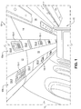
- FIG. 1 depicts one embodiment of an overhead PSU system 10 installed on the starboard side of an aircraft interior cabin IC (i.e., the starboard side of the aircraft's longitudinal centerline) according to one embodiment of the invention.
- an aircraft interior cabin IC is merely an exemplary embodiment of the invention since the PSU system 10 could equally be employed in other transport vehicles (e.g., trains, busses, boats and the like)
- transport vehicles e.g., trains, busses, boats and the like
- the PSU system 10 will include inboard and outboard (i.e., relative to the aircraft's longitudinal centerline) PSU assemblies 10a, 10b that are oriented generally parallel to the aircraft's longitudinal axis and positioned generally overhead of each inboard and outboard passenger seat (not shown) in a seat row.
- the PSU assemblies 10a, 10b are latitudinally separated from one another (i.e., relative to a latitudinal axis of the aircraft) by an aligned series of spacer panels 12.
- the PSU system 10 may be provided in combination with an overhead bin assembly 14 for storage of a passenger's carry-on articles.
- Overhead aisle lighting units 16 may be provided in the aircraft interior cabin IC to illuminate the center passenger aisle between seat rows.
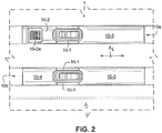
- the inboard PSU assembly 10a may be formed of a number of modular components assembled end-to-end in a series.
- the inboard PSU assembly 10a may include a modular PSU component 10-1 which is positioned between a modular audio speaker component 10-2 having an audio speaker 10-2a which allows for audio output of, e.g., cabin crew announcements and the like, and a modular lengthwise spacer component 10-3.
- the outboard PSU assembly 10b may include a modular PSU component 10-1 positioned between a modular emergency oxygen component 10-4 and a modular lengthwise spacer component 10-3.
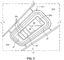
- FIG. 3 is an enlarged perspective view of the modular PSU component 10-1.
- the embodiment of the modular PSU component 10-1 includes several functions for passenger comfort and in-flight service.
- the modular PSU component 10-1 will preferably include at one end a light unit 20 which may be activated/deactivated by pressing the light switch 20a to provide the illumination of the passenger's individual seated space.
- An attendant call button 22 may be provided at an opposite end of the switch 20a to provide an alert to flight attendants that a passenger may need some assistance.
- the modular PSU component 10-1 is also provided with an air flow outlet diverter 24 in the form of pivotal vanes 24a that may be manually manipulated by a passenger's fingers inserted into a central recessed channel 26.
- a perimeter light band 28 can be provided with a light (e.g., a white light or a soothing colored light such as green or blue) which can be activated by flight attendants during aircraft boarding/unboarding.
- inboard and outboard PSU assemblies 10a, 10b as depicted in FIGS. 1 and 2 are substantially parallel to one another and to the aircraft's longitudinal axis (i.e., axis A L in FIG. 2 ).
- modular PSU components 10-1 of the inboard and outboard assemblies 10a, 10b are aligned with one another along the aircrafts latitudinal axis (i.e., an axis perpendicular to axis A L ).
- the embodiment of the inboard and outboard assemblies 10a, 10b is especially adapted for use in combination with a side-by-side seating arrangement within the interior cabin IC whereby the seats are positioned in a row aligned with the aircraft's latitudinal axis. In such an arrangement, therefore, the individual seats in the row are aligned with a common coincident latitudinal axis.
- a side-by-side seating arrangement within the interior cabin IC whereby the seats are positioned in a row aligned with the aircraft's latitudinal axis.
- the modular components of the inboard and outboard assemblies 10a, 10b could be constructed so that the individual modular PSU components 10-1 thereof are staggered in the direction of the aircraft's longitudinal axis to thereby permit individual aircraft seats to likewise be staggered (i.e., such that each seat is arranged relative to a respective latitudinal axis that is longitudinally separated from a latitudinal axis of an adjacent seat).
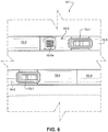
- FIG. 4 An exemplary array of possible modular components that may be assembled in an end-to-end manner relative to one another so as to provide the inboard and outboard PSU assemblies 10a, 10b, respectively, is depicted in FIG. 4 .
- both the modular emergency oxygen components 10-4 and modular lengthwise spacer components 10-3 may be provided with varying lengthwise dimensions to allow the layout of the modular PSU components 10-1 in an aligned configuration (e.g., as shown in FIG. 2 ) or to allow the modular PSU components to be staggered relative to one another (e.g., as shown in FIGS. 5 and 6 ).
- the varying lengths of the modular emergency oxygen components 10-4 and modular lengthwise spacer components 10-3 additionally allow the PSU assemblies 10a, 10b to be accommodated within different sizes of aircraft interior cabins IC.
- the different lengthwise dimensions of the emergency oxygen components 10-4 will allow at least one emergency oxygen delivery system (e.g., oxygen masks and associated tubing that is operatively connected to the aircraft's on-board emergency oxygen system which deploy automatically in response to depressurization of the aircraft's interior cabin IC) to be installed in dependence upon the passenger seat layout. Due to the modular nature of the components, therefore, greater flexibility in layouts of the PSU component 10-1 can be achieved.
- FIGS. 5 and 6 depict a staggered arrangement of the modular PSU components 10-1 associated with the inboard and outboard PSU assemblies 10a', 10b', respectively, associated with the PSU system 10'.
- the inboard PSU assembly 10a' may include adjacently positioned modular PSU and speaker components 10-1 and 10-2 in a manner similar to the embodiment described previously (see FIG. 2 ).
- modular longitudinal spacers 10-3 of greater length as compared to the modular longitudinal spacers 10-3 associated with the outboard PSU assembly 10b' thereby physically staggering the modular PSU components 10-1 relative to the aircraft's longitudinal axis A L (which in turn allows the individual passenger seats to be physically staggered for improved spatial passenger comfort).
- the modular emergency oxygen components 10-4 may be provided in the outboard PSU assembly 10b' and are of a sufficient lengthwise dimension so as to house multiple (at least two) emergency oxygen delivery systems (i.e., so as to provide emergency oxygen delivery to each occupant of the staggered seats below the modular PSU components 10-1).
Description
- The embodiments disclosed herein relate generally to passenger service units and assemblies thereof that may be employed in interiors of transport vehicles, especially aircraft interior cabins.
- The general part of
US 3370813 discussing the state of the art discloses the features of the preamble ofclaim 1. - The traditional Passenger Service Units (PSUs) for transport category commercial aircraft are typically a one-piece unit that integrally accommodates multiple service functions for passenger comfort and/or safety, such as air flow, reading lights, crew assistance call buttons, crew messages and concealed oxygen delivery masks. Usually the conventional PSU will located overhead in such a manner that passengers seated side-by-side in the same row will need to share PSU controls associate with their particular seat. Such a sharing arrangement can present uncomfortable situations during use, for example, by a passenger's forearm and/or elbow inadvertently striking an adjacent passenger's head or at least invading the adjacent passenger's personal space when reaching to operate the PSU controls.
- Conventional PSUs also do not have the passenger-operated controls (e.g., individual reading lights and air flow nozzles) positioned at an optimal location for each seat in a row. That is, since the conventional once piece PSUs are oriented along the aircraft's longitudinal axis, they must be positioned such that all passengers seated in a row (i.e., seated side-by-side along an axis transverse to the aircraft's longitudinal axis), they necessarily must be located overhead so as to be accessible by all passengers in that row. This means that a conventional PSU must be located overhead in such a manner that it is capable of servicing all passengers in the row, which in turn dictates that the PSU cannot be accessed comfortably by all such passengers (i.e., causing some of the passengers to reach across another passenger when it is necessary to operate the PSU functions). In addition, it is a common occurance that the reading light and/or air flow may encounter interference or obstruction from an immediately adjacent passenger.
- The conventional one-piece PSUs are also inflexible as to cabin arrangement options that may be available to the interior design. For example, the conventional one-piece PSU must be oriented along a common longitudinal axis and thus cannot be positioned along another longitudinal axis in order to accommodate passenger seats in a different side-by-side coordinate relationship.
- One proposal in the art is provided by
US Patent Application Publication 2012/0012707 which suggests that passenger supply functions be integrated in a storage compartment module that may be automatically hooked up to the supply system of the aircraft during mechanical installation of the module on a load-bearing structure of the cabin. - Further improvements and solutions to the problems noted previously are however needed. Therefore, what has been needed in this art are PSUs that have installation flexibility so as to provide optimum location of passenger service functions to minimize or substantially eliminate the problems associated with conventional one-piece PSUs. It is towards fulfilling such a need that the embodiments of the present invention are directed.
- In general, the embodiments disclosed herein are directed toward passenger service units and assemblies thereof. According to certain embodiments, elongate passenger service unit (PSU) assemblies are comprised of a plurality of modular passenger service components, and a plurality of variable-length modular spacer components. The modular spacer units are positioned between the modular passenger service units in an end-to-end manner so as to provide a desired lengthwise array of the passenger service units along the PSU assembly.
- According to some embodiments, the PSU assemblies will further comprise at least one modular audio speaker unit connected in an end-to-end manner with at least one of the modular passenger service components. In accordance with
claim 1 the modular emergency oxygen components will be connected in an end-to-end manner with at least one of the modular passenger service components and the modular emergency oxygen components are of variable length as compared to others of the modular emergency oxygen components, each respectively accommodating at least one emergency oxygen delivery system therewithin. - The modular passenger service units included in the PSU assemblies may include a light unit and a light switch to activate/deactivate the light unit, an attendant call button and an air flow outlet diverter. According to some embodiments, the air flow outlet diverter may be in the form of a plurality of pivotal vanes, in which case a recessed channel may be provided adjacent to the vanes to allow for manual manipulation thereof. A perimeter light band may be provided so as to bound the light unit, attendant call button and air flow diverter.
- Transport category vehicles, e.g., aircraft, may thus be provided with inboard and outboard PSU assemblies. The passenger seats may be arranged in a latitudinally side-by-side arrangement and/or may be arranged in a longitudinally staggered arrangement. By providing variable length modular spacer units, therefore, the individual passenger service units may be arranged directly overhead of each passenger seat.
- These and other aspects and advantages of the present invention will become more clear after careful consideration is given to the following detailed description of the preferred exemplary embodiments thereof.
- The disclosed embodiments of the present invention will be better and more completely understood by referring to the following detailed description of exemplary non-limiting illustrative embodiments in conjunction with the drawings of which:
-
FIG. 1 is partial perspective view of an interior aircraft cabin showing an overhead PSU assembly of modular passenger service components according to one embodiment of the invention on a starboard side of the aircraft cabin (i.e., the starboard side of the aircraft's centerline); -
FIG. 2 is a plan view of the overhead PSU assembly depicted inFIG. 1 as seen from below; -
FIG. 3 is an enlarged view from a seated passenger's perspective of a modular PSU component employed in the overhead PSU assembly depicted inFIG. 1 ; -
FIG. 4 is an exploded plan view showing various modular PSU components that may be grouped as needed according to aircraft interior design to form overhead PSU assemblies according to the invention; -
FIG. 5 is perspective as viewed from below showing an overhead PSU assembly of modular passenger service components according to another embodiment of the invention; and -
FIG. 6 is a plan view of the overhead PSU assembly depicted inFIG. 5 as seen from below. - Accompanying
FIG. 1 depicts one embodiment of anoverhead PSU system 10 installed on the starboard side of an aircraft interior cabin IC (i.e., the starboard side of the aircraft's longitudinal centerline) according to one embodiment of the invention. It will be understood that reference to an aircraft interior cabin IC is merely an exemplary embodiment of the invention since thePSU system 10 could equally be employed in other transport vehicles (e.g., trains, busses, boats and the like) It will also be appreciated that the discussion below is equally applicable to anoverhead PSU system 10 installed on the port side of the aircraft interior cabin in the form of a mirror image of the starboard side installation. - As shown, the
PSU system 10 will include inboard and outboard (i.e., relative to the aircraft's longitudinal centerline) PSU assemblies 10a, 10b that are oriented generally parallel to the aircraft's longitudinal axis and positioned generally overhead of each inboard and outboard passenger seat (not shown) in a seat row. The PSU assemblies 10a, 10b are latitudinally separated from one another (i.e., relative to a latitudinal axis of the aircraft) by an aligned series ofspacer panels 12. ThePSU system 10 may be provided in combination with anoverhead bin assembly 14 for storage of a passenger's carry-on articles. Overheadaisle lighting units 16 may be provided in the aircraft interior cabin IC to illuminate the center passenger aisle between seat rows. - Accompanying
FIG. 2 depicts in greater detail theoverhead PSU system 10 that is shown inFIG. 1 . In this regard, it will be observed that theinboard PSU assembly 10a may be formed of a number of modular components assembled end-to-end in a series. By way of example, theinboard PSU assembly 10a may include a modular PSU component 10-1 which is positioned between a modular audio speaker component 10-2 having an audio speaker 10-2a which allows for audio output of, e.g., cabin crew announcements and the like, and a modular lengthwise spacer component 10-3. By way of further example, theoutboard PSU assembly 10b may include a modular PSU component 10-1 positioned between a modular emergency oxygen component 10-4 and a modular lengthwise spacer component 10-3. - Accompanying
FIG. 3 is an enlarged perspective view of the modular PSU component 10-1. As can be seen, the embodiment of the modular PSU component 10-1 includes several functions for passenger comfort and in-flight service. Specifically, the modular PSU component 10-1 will preferably include at one end alight unit 20 which may be activated/deactivated by pressing thelight switch 20a to provide the illumination of the passenger's individual seated space. Anattendant call button 22 may be provided at an opposite end of theswitch 20a to provide an alert to flight attendants that a passenger may need some assistance. - The modular PSU component 10-1 is also provided with an air flow outlet diverter 24 in the form of
pivotal vanes 24a that may be manually manipulated by a passenger's fingers inserted into a central recessedchannel 26. Aperimeter light band 28 can be provided with a light (e.g., a white light or a soothing colored light such as green or blue) which can be activated by flight attendants during aircraft boarding/unboarding. - It will be observed that the inboard and outboard PSU assemblies 10a, 10b as depicted in
FIGS. 1 and2 are substantially parallel to one another and to the aircraft's longitudinal axis (i.e., axis AL inFIG. 2 ). Moreover, modular PSU components 10-1 of the inboard andoutboard assemblies outboard assemblies FIGS. 5 and6 , the modular components of the inboard andoutboard assemblies - An exemplary array of possible modular components that may be assembled in an end-to-end manner relative to one another so as to provide the inboard and
outboard PSU assemblies FIG. 4 . As is shown, both the modular emergency oxygen components 10-4 and modular lengthwise spacer components 10-3 may be provided with varying lengthwise dimensions to allow the layout of the modular PSU components 10-1 in an aligned configuration (e.g., as shown inFIG. 2 ) or to allow the modular PSU components to be staggered relative to one another (e.g., as shown inFIGS. 5 and6 ). The varying lengths of the modular emergency oxygen components 10-4 and modular lengthwise spacer components 10-3 additionally allow the PSU assemblies 10a, 10b to be accommodated within different sizes of aircraft interior cabins IC. In addition, the different lengthwise dimensions of the emergency oxygen components 10-4 will allow at least one emergency oxygen delivery system (e.g., oxygen masks and associated tubing that is operatively connected to the aircraft's on-board emergency oxygen system which deploy automatically in response to depressurization of the aircraft's interior cabin IC) to be installed in dependence upon the passenger seat layout. Due to the modular nature of the components, therefore, greater flexibility in layouts of the PSU component 10-1 can be achieved. - Accompanying
FIGS. 5 and6 depict a staggered arrangement of the modular PSU components 10-1 associated with the inboard andoutboard PSU assemblies 10a', 10b', respectively, associated with the PSU system 10'. By way of example, theinboard PSU assembly 10a' may include adjacently positioned modular PSU and speaker components 10-1 and 10-2 in a manner similar to the embodiment described previously (seeFIG. 2 ). However, unlike the previously described embodiment, modular longitudinal spacers 10-3 of greater length as compared to the modular longitudinal spacers 10-3 associated with theoutboard PSU assembly 10b' thereby physically staggering the modular PSU components 10-1 relative to the aircraft's longitudinal axis AL (which in turn allows the individual passenger seats to be physically staggered for improved spatial passenger comfort). The modular emergency oxygen components 10-4 may be provided in theoutboard PSU assembly 10b' and are of a sufficient lengthwise dimension so as to house multiple (at least two) emergency oxygen delivery systems (i.e., so as to provide emergency oxygen delivery to each occupant of the staggered seats below the modular PSU components 10-1). - Using various combinations of the modular components 10-1 through 10-4 as described above, the aircraft interior designer will have greater flexibility to design passenger seating layouts that is currently possible with conventional one-piece PSUs. Therefore, it will be understood that the description provided herein is presently considered to be the most practical and preferred embodiments of the invention. Thus, the invention is not to be limited to the disclosed embodiments, but on the contrary, is intended to cover various modifications and equivalent arrangements included within the scope thereof.
Claims (12)
- An elongate passenger service unit, PSU, assembly (10, 10a, 10b) formed of a number of modular components assembled end-to-end in a series, the assembly comprising:a plurality of modular passenger service components (10-1); anda plurality of modular spacer components (10-3) having varying lengthwise dimensions; whereinthe modular spacer components (10-3) are positioned between the modular passenger service components (10-1) in an end-to-end manner so as to provide a desired lengthwise array of the passenger service components along the PSU assembly;characterised by the PSU assembly further comprising:a plurality of modular emergency oxygen components (10-4) having varying lengthwise dimensions,each respectively accommodating at least one emergency oxygen delivery system therewithin, the modular emergency oxygen components (10-4) being connected in an end-to-end manner with the modular passenger service components (10-1).
- The PSU assembly as in claim 1, further comprising at least one modular audio speaker component (10-2) connected in an end-to-end manner with at least one of the modular passenger service components.
- The PSU assembly as in one of the preceding claims, wherein each modular passenger service component (10-1) comprises:a light unit (20) and a light switch (20a) to activate/deactivate the light unit;an attendant call button; button (22); andan air flow outlet diverter.
- The PSU assembly as in claim 3, wherein the air flow outlet (24) comprises a plurality of pivotal vanes (24a).
- The PSU assembly as in claim 4, wherein each of the modular passenger service components (10-1) comprises a recessed channel (26) adjacent to the pivotal vanes (24a) to allow for manual manipulation thereof.
- The PSU assembly as in one of claims 3 to 5, further comprising a perimeter light band (28) which bounds the light unit, attendant call button and air flow diverter.
- An aircraft comprising an interior cabin, passenger seats arranged side-by-side within the interior cabin, and parallel inboard and outboard PSU assemblies (10, 10a, 10b) positioned overhead each of the passenger seats in a lengthwise direction of the interior cabin, wherein each of the PSU assemblies comprises the features of one of the preceding claims, wherein each of the passenger service components is positioned overhead a respective one of the passenger seats.
- The aircraft as in claim 7, wherein the passenger seats are latitudinally aligned with one another, and wherein the modular spacer components (10-3) are positioned between the passenger service components (10-1) so that adjacent ones of the passenger service components in the inboard and outboard PSU assemblies are latitudinally aligned with one another.
- The aircraft as in claim 7 or claim 8, wherein the passenger seats are longitudinally staggered relative to one another, and wherein the modular spacer components (10-3) are positioned between the passenger service components (10-1) so that adjacent ones of the passenger service components in the inboard and outboard PSU assemblies longitudinally staggered with one another.
- The aircraft as in one of claims 7 to 9, further comprising spacer panels (12) positioned between the inboard and outboard PSU assemblies.
- The aircraft as in one of claims 7 to 10, wherein the interior cabin further comprises overhead storage bins (14), wherein the inboard and outboard PSU assemblies are provided at a lower extent of the overhead storage bins.
- The aircraft as in claim 11, wherein the interior cabin further comprises an overhead aisle lighting unit (16), wherein the overhead storage bins (14) and the inboard and outboard PSU assemblies (10, 10b) are positioned laterally of the overhead aisle lighting unit.
Applications Claiming Priority (1)
| Application Number | Priority Date | Filing Date | Title |
|---|---|---|---|
| US201361887313P | 2013-10-04 | 2013-10-04 |
Publications (2)
| Publication Number | Publication Date |
|---|---|
| EP2857314A1 EP2857314A1 (en) | 2015-04-08 |
| EP2857314B1 true EP2857314B1 (en) | 2017-07-12 |
Family
ID=51862084
Family Applications (1)
| Application Number | Title | Priority Date | Filing Date |
|---|---|---|---|
| EP14187547.6A Active EP2857314B1 (en) | 2013-10-04 | 2014-10-02 | Modular passenger service units and assemblies thereof |
Country Status (6)
| Country | Link |
|---|---|
| US (1) | US9481462B2 (en) |
| EP (1) | EP2857314B1 (en) |
| CN (1) | CN104512552B (en) |
| BR (1) | BR102014024026B1 (en) |
| IN (1) | IN2014DE02803A (en) |
| RU (1) | RU2670187C2 (en) |
Families Citing this family (17)
| Publication number | Priority date | Publication date | Assignee | Title |
|---|---|---|---|---|
| DE102010018502A1 (en) * | 2010-04-28 | 2011-11-03 | Airbus Operations Gmbh | Supply system for supplying passengers in a passenger compartment of a vehicle |
| DE102011110010A1 (en) * | 2011-08-11 | 2013-02-14 | Airbus Operations Gmbh | Passenger supply module with integrated cabin lighting |
| EP2801523B1 (en) * | 2013-05-06 | 2017-10-25 | Airbus Operations GmbH | Passenger supply system for installation in a passenger supply channel |
| WO2016126255A1 (en) * | 2015-02-02 | 2016-08-11 | C&D Zodiac Inc. | Passenger service unit pod assembly |
| US10239617B2 (en) * | 2015-09-11 | 2019-03-26 | The Boeing Company | Oxygen box for a limited maintenance access area above a ceiling panel of an aircraft cabin |
| EP3147201A1 (en) * | 2015-09-28 | 2017-03-29 | Goodrich Lighting Systems GmbH | Aircraft passenger service unit mounting kit |
| WO2017201207A1 (en) * | 2016-05-18 | 2017-11-23 | Airbus Group Hq Inc. Dba A3 By Airbus Group | Systems, devices, and methods for a modular passenger aircraft cabin and design thereof |
| USD902837S1 (en) * | 2017-10-30 | 2020-11-24 | Textron Innovations, Inc. | Large cabin overhead |
| EP3560835A1 (en) * | 2018-04-27 | 2019-10-30 | Bombardier Inc. | Universal passenger service unit |
| US10822088B2 (en) * | 2018-05-11 | 2020-11-03 | B/E Aerospace, Inc. | Unified passenger service unit (PSU) control |
| WO2020024336A1 (en) * | 2018-08-03 | 2020-02-06 | 李宗谕 | Mounting structure in civil aircraft cabin |
| CN109229406A (en) * | 2018-10-17 | 2019-01-18 | 成都戎创航空科技有限公司 | Aircraft high-frequency communication warning system |
| WO2020124216A1 (en) * | 2018-12-21 | 2020-06-25 | Bombardier Inc. | Air deflector and system including the air deflector |
| US20200262559A1 (en) * | 2019-02-20 | 2020-08-20 | Goodrich Corporation | Service light integrated with reading light switch |
| DE102020104797A1 (en) * | 2020-02-24 | 2021-08-26 | Airbus Operations Gmbh | Passenger service unit with textile cover, passenger seating area and vehicle with passenger service unit |
| CN111976993A (en) * | 2020-09-01 | 2020-11-24 | 中国航空工业集团公司上海航空测控技术研究所 | Passenger service device for aircraft passenger cabin |
| US20220411062A1 (en) * | 2021-06-29 | 2022-12-29 | The Boeing Company | Emergency oxygen systems for internal cabins of aircraft |
Family Cites Families (11)
| Publication number | Priority date | Publication date | Assignee | Title |
|---|---|---|---|---|
| US3370813A (en) * | 1965-10-22 | 1968-02-27 | Mc Donnell Douglas Corp | Adjustable passenger reading lights and utilities |
| US5395074A (en) * | 1993-03-10 | 1995-03-07 | Health Tecna Aerospace Company A Unit Of Ciba-Geigy | Retrofit bezel assembly |
| DE50202608D1 (en) * | 2001-09-03 | 2005-05-04 | Goodrich Hella Aerospace Ls | Cladding element for the interior of a vehicle, in particular an aircraft |
| EP1687202A2 (en) * | 2003-11-07 | 2006-08-09 | Weber Aircraft LP | Emergency oxygen or other gas supply system |
| US8166506B2 (en) * | 2005-09-12 | 2012-04-24 | The Boeing Company | Simplified cabin services system for an aircraft |
| CA123616S (en) | 2007-06-11 | 2008-11-25 | Mitsubishi Heavy Ind Ltd | Vehicle ceiling panel for lighting and air-conditioning |
| DE102007049926A1 (en) * | 2007-10-18 | 2009-04-23 | Airbus Deutschland Gmbh | System and method for air conditioning at least a portion of an aircraft |
| DE102009014599A1 (en) * | 2009-03-24 | 2010-09-30 | Airbus Deutschland Gmbh | Integration of supply functions in a storage compartment |
| DE102009058227A1 (en) * | 2009-12-14 | 2011-06-16 | Airbus Operations Gmbh | Acoustically optimized air conditioning components |
| DE102009054698A1 (en) * | 2009-12-15 | 2011-06-16 | Airbus Operations Gmbh | Method for positioning at least one component, in particular a seat, in or on an aircraft or spacecraft, and aircraft or spacecraft |
| JP2011140264A (en) * | 2010-01-07 | 2011-07-21 | Jamco Corp | Aircraft cabin lighting system |
-
2014
- 2014-08-08 US US14/455,452 patent/US9481462B2/en active Active
- 2014-09-26 BR BR102014024026-8A patent/BR102014024026B1/en active IP Right Grant
- 2014-09-30 IN IN2803DE2014 patent/IN2014DE02803A/en unknown
- 2014-09-30 RU RU2014139667A patent/RU2670187C2/en active
- 2014-10-02 EP EP14187547.6A patent/EP2857314B1/en active Active
- 2014-10-08 CN CN201410648004.0A patent/CN104512552B/en active Active
Non-Patent Citations (1)
| Title |
|---|
| None * |
Also Published As
| Publication number | Publication date |
|---|---|
| RU2670187C2 (en) | 2018-10-18 |
| EP2857314A1 (en) | 2015-04-08 |
| BR102014024026B1 (en) | 2022-05-17 |
| IN2014DE02803A (en) | 2015-06-26 |
| CN104512552A (en) | 2015-04-15 |
| US20150097082A1 (en) | 2015-04-09 |
| CN104512552B (en) | 2019-04-12 |
| US9481462B2 (en) | 2016-11-01 |
| RU2014139667A (en) | 2016-04-20 |
| BR102014024026A2 (en) | 2016-02-16 |
Similar Documents
| Publication | Publication Date | Title |
|---|---|---|
| EP2857314B1 (en) | Modular passenger service units and assemblies thereof | |
| US20200298976A1 (en) | Aircraft lounge assembly | |
| US8534604B2 (en) | Seat shell and integrated overhead storage bin | |
| US6073883A (en) | Aircraft overhead rest areas | |
| US8991756B2 (en) | Small diameter pressure structure commercial aircraft crew rest | |
| US9067683B2 (en) | Support structure for use in an air supply arrangement and service supply system comprising said type of support structure and method for configuration | |
| US9045235B2 (en) | Service device, passenger service unit, fuselage of an aircraft, method for installing the service device | |
| US9340287B2 (en) | Passenger service system with improved air guidance | |
| US11702207B2 (en) | Business class seats for a passenger vehicle | |
| US20090017742A1 (en) | Ionized-re-circulating air-aircraft | |
| US8720820B2 (en) | Aircraft having multiple seating configurations and associated systems and methods | |
| US11161614B2 (en) | Vehicle business class seat and stowage system | |
| WO2020208420A1 (en) | Air gasper with integrated fan | |
| WO2020076369A1 (en) | Double cabin attendant seat | |
| US8167243B2 (en) | Systems and methods to provide optical enlargement of passenger interior cabin space | |
| EP3126241B1 (en) | Shared entrance seating arrangement | |
| US20150008283A1 (en) | Aircraft seating unit with fixture member | |
| EP2821345A1 (en) | Aircraft seating unit with fixture member |
Legal Events
| Date | Code | Title | Description |
|---|---|---|---|
| PUAI | Public reference made under article 153(3) epc to a published international application that has entered the european phase |
Free format text: ORIGINAL CODE: 0009012 |
|
| 17P | Request for examination filed |
Effective date: 20141002 |
|
| AK | Designated contracting states |
Kind code of ref document: A1 Designated state(s): AL AT BE BG CH CY CZ DE DK EE ES FI FR GB GR HR HU IE IS IT LI LT LU LV MC MK MT NL NO PL PT RO RS SE SI SK SM TR |
|
| AX | Request for extension of the european patent |
Extension state: BA ME |
|
| RAP1 | Party data changed (applicant data changed or rights of an application transferred) |
Owner name: EMBRAER S.A. |
|
| R17P | Request for examination filed (corrected) |
Effective date: 20151008 |
|
| RBV | Designated contracting states (corrected) |
Designated state(s): AL AT BE BG CH CY CZ DE DK EE ES FI FR GB GR HR HU IE IS IT LI LT LU LV MC MK MT NL NO PL PT RO RS SE SI SK SM TR |
|
| 17Q | First examination report despatched |
Effective date: 20160401 |
|
| GRAP | Despatch of communication of intention to grant a patent |
Free format text: ORIGINAL CODE: EPIDOSNIGR1 |
|
| RIC1 | Information provided on ipc code assigned before grant |
Ipc: B64C 1/06 20060101ALI20170130BHEP Ipc: B64C 1/12 20060101ALI20170130BHEP Ipc: B64D 13/00 20060101ALI20170130BHEP Ipc: B64D 11/00 20060101AFI20170130BHEP Ipc: A62B 7/14 20060101ALI20170130BHEP |
|
| INTG | Intention to grant announced |
Effective date: 20170215 |
|
| GRAS | Grant fee paid |
Free format text: ORIGINAL CODE: EPIDOSNIGR3 |
|
| GRAA | (expected) grant |
Free format text: ORIGINAL CODE: 0009210 |
|
| AK | Designated contracting states |
Kind code of ref document: B1 Designated state(s): AL AT BE BG CH CY CZ DE DK EE ES FI FR GB GR HR HU IE IS IT LI LT LU LV MC MK MT NL NO PL PT RO RS SE SI SK SM TR |
|
| REG | Reference to a national code |
Ref country code: GB Ref legal event code: FG4D |
|
| REG | Reference to a national code |
Ref country code: CH Ref legal event code: EP |
|
| REG | Reference to a national code |
Ref country code: AT Ref legal event code: REF Ref document number: 908077 Country of ref document: AT Kind code of ref document: T Effective date: 20170715 |
|
| REG | Reference to a national code |
Ref country code: IE Ref legal event code: FG4D |
|
| REG | Reference to a national code |
Ref country code: DE Ref legal event code: R096 Ref document number: 602014011667 Country of ref document: DE |
|
| REG | Reference to a national code |
Ref country code: FR Ref legal event code: PLFP Year of fee payment: 4 |
|
| REG | Reference to a national code |
Ref country code: NL Ref legal event code: MP Effective date: 20170712 |
|
| REG | Reference to a national code |
Ref country code: LT Ref legal event code: MG4D |
|
| REG | Reference to a national code |
Ref country code: AT Ref legal event code: MK05 Ref document number: 908077 Country of ref document: AT Kind code of ref document: T Effective date: 20170712 |
|
| PG25 | Lapsed in a contracting state [announced via postgrant information from national office to epo] |
Ref country code: LT Free format text: LAPSE BECAUSE OF FAILURE TO SUBMIT A TRANSLATION OF THE DESCRIPTION OR TO PAY THE FEE WITHIN THE PRESCRIBED TIME-LIMIT Effective date: 20170712 Ref country code: FI Free format text: LAPSE BECAUSE OF FAILURE TO SUBMIT A TRANSLATION OF THE DESCRIPTION OR TO PAY THE FEE WITHIN THE PRESCRIBED TIME-LIMIT Effective date: 20170712 Ref country code: AT Free format text: LAPSE BECAUSE OF FAILURE TO SUBMIT A TRANSLATION OF THE DESCRIPTION OR TO PAY THE FEE WITHIN THE PRESCRIBED TIME-LIMIT Effective date: 20170712 Ref country code: HR Free format text: LAPSE BECAUSE OF FAILURE TO SUBMIT A TRANSLATION OF THE DESCRIPTION OR TO PAY THE FEE WITHIN THE PRESCRIBED TIME-LIMIT Effective date: 20170712 Ref country code: SE Free format text: LAPSE BECAUSE OF FAILURE TO SUBMIT A TRANSLATION OF THE DESCRIPTION OR TO PAY THE FEE WITHIN THE PRESCRIBED TIME-LIMIT Effective date: 20170712 Ref country code: NO Free format text: LAPSE BECAUSE OF FAILURE TO SUBMIT A TRANSLATION OF THE DESCRIPTION OR TO PAY THE FEE WITHIN THE PRESCRIBED TIME-LIMIT Effective date: 20171012 Ref country code: NL Free format text: LAPSE BECAUSE OF FAILURE TO SUBMIT A TRANSLATION OF THE DESCRIPTION OR TO PAY THE FEE WITHIN THE PRESCRIBED TIME-LIMIT Effective date: 20170712 |
|
| PG25 | Lapsed in a contracting state [announced via postgrant information from national office to epo] |
Ref country code: GR Free format text: LAPSE BECAUSE OF FAILURE TO SUBMIT A TRANSLATION OF THE DESCRIPTION OR TO PAY THE FEE WITHIN THE PRESCRIBED TIME-LIMIT Effective date: 20171013 Ref country code: PL Free format text: LAPSE BECAUSE OF FAILURE TO SUBMIT A TRANSLATION OF THE DESCRIPTION OR TO PAY THE FEE WITHIN THE PRESCRIBED TIME-LIMIT Effective date: 20170712 Ref country code: RS Free format text: LAPSE BECAUSE OF FAILURE TO SUBMIT A TRANSLATION OF THE DESCRIPTION OR TO PAY THE FEE WITHIN THE PRESCRIBED TIME-LIMIT Effective date: 20170712 Ref country code: IS Free format text: LAPSE BECAUSE OF FAILURE TO SUBMIT A TRANSLATION OF THE DESCRIPTION OR TO PAY THE FEE WITHIN THE PRESCRIBED TIME-LIMIT Effective date: 20171112 Ref country code: BG Free format text: LAPSE BECAUSE OF FAILURE TO SUBMIT A TRANSLATION OF THE DESCRIPTION OR TO PAY THE FEE WITHIN THE PRESCRIBED TIME-LIMIT Effective date: 20171012 Ref country code: ES Free format text: LAPSE BECAUSE OF FAILURE TO SUBMIT A TRANSLATION OF THE DESCRIPTION OR TO PAY THE FEE WITHIN THE PRESCRIBED TIME-LIMIT Effective date: 20170712 Ref country code: LV Free format text: LAPSE BECAUSE OF FAILURE TO SUBMIT A TRANSLATION OF THE DESCRIPTION OR TO PAY THE FEE WITHIN THE PRESCRIBED TIME-LIMIT Effective date: 20170712 |
|
| REG | Reference to a national code |
Ref country code: DE Ref legal event code: R097 Ref document number: 602014011667 Country of ref document: DE |
|
| PG25 | Lapsed in a contracting state [announced via postgrant information from national office to epo] |
Ref country code: CZ Free format text: LAPSE BECAUSE OF FAILURE TO SUBMIT A TRANSLATION OF THE DESCRIPTION OR TO PAY THE FEE WITHIN THE PRESCRIBED TIME-LIMIT Effective date: 20170712 Ref country code: RO Free format text: LAPSE BECAUSE OF FAILURE TO SUBMIT A TRANSLATION OF THE DESCRIPTION OR TO PAY THE FEE WITHIN THE PRESCRIBED TIME-LIMIT Effective date: 20170712 Ref country code: DK Free format text: LAPSE BECAUSE OF FAILURE TO SUBMIT A TRANSLATION OF THE DESCRIPTION OR TO PAY THE FEE WITHIN THE PRESCRIBED TIME-LIMIT Effective date: 20170712 |
|
| PLBE | No opposition filed within time limit |
Free format text: ORIGINAL CODE: 0009261 |
|
| STAA | Information on the status of an ep patent application or granted ep patent |
Free format text: STATUS: NO OPPOSITION FILED WITHIN TIME LIMIT |
|
| PG25 | Lapsed in a contracting state [announced via postgrant information from national office to epo] |
Ref country code: SK Free format text: LAPSE BECAUSE OF FAILURE TO SUBMIT A TRANSLATION OF THE DESCRIPTION OR TO PAY THE FEE WITHIN THE PRESCRIBED TIME-LIMIT Effective date: 20170712 Ref country code: MC Free format text: LAPSE BECAUSE OF FAILURE TO SUBMIT A TRANSLATION OF THE DESCRIPTION OR TO PAY THE FEE WITHIN THE PRESCRIBED TIME-LIMIT Effective date: 20170712 Ref country code: IT Free format text: LAPSE BECAUSE OF FAILURE TO SUBMIT A TRANSLATION OF THE DESCRIPTION OR TO PAY THE FEE WITHIN THE PRESCRIBED TIME-LIMIT Effective date: 20170712 Ref country code: EE Free format text: LAPSE BECAUSE OF FAILURE TO SUBMIT A TRANSLATION OF THE DESCRIPTION OR TO PAY THE FEE WITHIN THE PRESCRIBED TIME-LIMIT Effective date: 20170712 Ref country code: SM Free format text: LAPSE BECAUSE OF FAILURE TO SUBMIT A TRANSLATION OF THE DESCRIPTION OR TO PAY THE FEE WITHIN THE PRESCRIBED TIME-LIMIT Effective date: 20170712 |
|
| REG | Reference to a national code |
Ref country code: CH Ref legal event code: PL |
|
| 26N | No opposition filed |
Effective date: 20180413 |
|
| REG | Reference to a national code |
Ref country code: IE Ref legal event code: MM4A |
|
| PG25 | Lapsed in a contracting state [announced via postgrant information from national office to epo] |
Ref country code: CH Free format text: LAPSE BECAUSE OF NON-PAYMENT OF DUE FEES Effective date: 20171031 Ref country code: LI Free format text: LAPSE BECAUSE OF NON-PAYMENT OF DUE FEES Effective date: 20171031 Ref country code: LU Free format text: LAPSE BECAUSE OF NON-PAYMENT OF DUE FEES Effective date: 20171002 |
|
| REG | Reference to a national code |
Ref country code: BE Ref legal event code: MM Effective date: 20171031 |
|
| PG25 | Lapsed in a contracting state [announced via postgrant information from national office to epo] |
Ref country code: SI Free format text: LAPSE BECAUSE OF FAILURE TO SUBMIT A TRANSLATION OF THE DESCRIPTION OR TO PAY THE FEE WITHIN THE PRESCRIBED TIME-LIMIT Effective date: 20170712 Ref country code: BE Free format text: LAPSE BECAUSE OF NON-PAYMENT OF DUE FEES Effective date: 20171031 |
|
| PG25 | Lapsed in a contracting state [announced via postgrant information from national office to epo] |
Ref country code: MT Free format text: LAPSE BECAUSE OF NON-PAYMENT OF DUE FEES Effective date: 20171002 |
|
| REG | Reference to a national code |
Ref country code: FR Ref legal event code: PLFP Year of fee payment: 5 |
|
| PG25 | Lapsed in a contracting state [announced via postgrant information from national office to epo] |
Ref country code: IE Free format text: LAPSE BECAUSE OF NON-PAYMENT OF DUE FEES Effective date: 20171002 |
|
| GBPC | Gb: european patent ceased through non-payment of renewal fee |
Effective date: 20181002 |
|
| PG25 | Lapsed in a contracting state [announced via postgrant information from national office to epo] |
Ref country code: HU Free format text: LAPSE BECAUSE OF FAILURE TO SUBMIT A TRANSLATION OF THE DESCRIPTION OR TO PAY THE FEE WITHIN THE PRESCRIBED TIME-LIMIT; INVALID AB INITIO Effective date: 20141002 |
|
| PG25 | Lapsed in a contracting state [announced via postgrant information from national office to epo] |
Ref country code: CY Free format text: LAPSE BECAUSE OF FAILURE TO SUBMIT A TRANSLATION OF THE DESCRIPTION OR TO PAY THE FEE WITHIN THE PRESCRIBED TIME-LIMIT Effective date: 20170712 Ref country code: GB Free format text: LAPSE BECAUSE OF NON-PAYMENT OF DUE FEES Effective date: 20181002 |
|
| PG25 | Lapsed in a contracting state [announced via postgrant information from national office to epo] |
Ref country code: MK Free format text: LAPSE BECAUSE OF FAILURE TO SUBMIT A TRANSLATION OF THE DESCRIPTION OR TO PAY THE FEE WITHIN THE PRESCRIBED TIME-LIMIT Effective date: 20170712 |
|
| PG25 | Lapsed in a contracting state [announced via postgrant information from national office to epo] |
Ref country code: TR Free format text: LAPSE BECAUSE OF FAILURE TO SUBMIT A TRANSLATION OF THE DESCRIPTION OR TO PAY THE FEE WITHIN THE PRESCRIBED TIME-LIMIT Effective date: 20170712 |
|
| REG | Reference to a national code |
Ref country code: DE Ref legal event code: R081 Ref document number: 602014011667 Country of ref document: DE Owner name: YABORA INDUSTRIA AERONAUTICA S.A., BR Free format text: FORMER OWNER: EMBRAER S.A., SAO JOSE DOS CAMPOS, SAO PAULO, BR Ref country code: DE Ref legal event code: R082 Ref document number: 602014011667 Country of ref document: DE Representative=s name: BOEHMERT & BOEHMERT ANWALTSPARTNERSCHAFT MBB -, DE |
|
| PG25 | Lapsed in a contracting state [announced via postgrant information from national office to epo] |
Ref country code: PT Free format text: LAPSE BECAUSE OF FAILURE TO SUBMIT A TRANSLATION OF THE DESCRIPTION OR TO PAY THE FEE WITHIN THE PRESCRIBED TIME-LIMIT Effective date: 20170712 |
|
| PG25 | Lapsed in a contracting state [announced via postgrant information from national office to epo] |
Ref country code: AL Free format text: LAPSE BECAUSE OF FAILURE TO SUBMIT A TRANSLATION OF THE DESCRIPTION OR TO PAY THE FEE WITHIN THE PRESCRIBED TIME-LIMIT Effective date: 20170712 |
|
| PGFP | Annual fee paid to national office [announced via postgrant information from national office to epo] |
Ref country code: FR Payment date: 20231009 Year of fee payment: 10 Ref country code: DE Payment date: 20231027 Year of fee payment: 10 |