EP2857270A2 - Energy management system in a vehicle and a method thereof - Google Patents
Energy management system in a vehicle and a method thereof Download PDFInfo
- Publication number
- EP2857270A2 EP2857270A2 EP14185879.5A EP14185879A EP2857270A2 EP 2857270 A2 EP2857270 A2 EP 2857270A2 EP 14185879 A EP14185879 A EP 14185879A EP 2857270 A2 EP2857270 A2 EP 2857270A2
- Authority
- EP
- European Patent Office
- Prior art keywords
- energy
- ecus
- request
- vehicle
- management system
- Prior art date
- Legal status (The legal status is an assumption and is not a legal conclusion. Google has not performed a legal analysis and makes no representation as to the accuracy of the status listed.)
- Granted
Links
- 238000000034 method Methods 0.000 title claims description 8
- 238000007726 management method Methods 0.000 description 20
- 239000007864 aqueous solution Substances 0.000 description 12
- 238000005265 energy consumption Methods 0.000 description 7
- 239000007788 liquid Substances 0.000 description 3
- IJGRMHOSHXDMSA-UHFFFAOYSA-N Atomic nitrogen Chemical compound N#N IJGRMHOSHXDMSA-UHFFFAOYSA-N 0.000 description 2
- 230000008014 freezing Effects 0.000 description 2
- 238000007710 freezing Methods 0.000 description 2
- 239000007789 gas Substances 0.000 description 2
- 238000010438 heat treatment Methods 0.000 description 2
- 239000000284 extract Substances 0.000 description 1
- 230000000977 initiatory effect Effects 0.000 description 1
- 230000004048 modification Effects 0.000 description 1
- 238000012986 modification Methods 0.000 description 1
- 238000012544 monitoring process Methods 0.000 description 1
- 229910052757 nitrogen Inorganic materials 0.000 description 1
- 230000021715 photosynthesis, light harvesting Effects 0.000 description 1
- 238000012913 prioritisation Methods 0.000 description 1
- 238000012358 sourcing Methods 0.000 description 1
Images

Classifications
-
- B—PERFORMING OPERATIONS; TRANSPORTING
- B60—VEHICLES IN GENERAL
- B60W—CONJOINT CONTROL OF VEHICLE SUB-UNITS OF DIFFERENT TYPE OR DIFFERENT FUNCTION; CONTROL SYSTEMS SPECIALLY ADAPTED FOR HYBRID VEHICLES; ROAD VEHICLE DRIVE CONTROL SYSTEMS FOR PURPOSES NOT RELATED TO THE CONTROL OF A PARTICULAR SUB-UNIT
- B60W10/00—Conjoint control of vehicle sub-units of different type or different function
- B60W10/30—Conjoint control of vehicle sub-units of different type or different function including control of auxiliary equipment, e.g. air-conditioning compressors or oil pumps
-
- B—PERFORMING OPERATIONS; TRANSPORTING
- B60—VEHICLES IN GENERAL
- B60W—CONJOINT CONTROL OF VEHICLE SUB-UNITS OF DIFFERENT TYPE OR DIFFERENT FUNCTION; CONTROL SYSTEMS SPECIALLY ADAPTED FOR HYBRID VEHICLES; ROAD VEHICLE DRIVE CONTROL SYSTEMS FOR PURPOSES NOT RELATED TO THE CONTROL OF A PARTICULAR SUB-UNIT
- B60W10/00—Conjoint control of vehicle sub-units of different type or different function
- B60W10/04—Conjoint control of vehicle sub-units of different type or different function including control of propulsion units
- B60W10/06—Conjoint control of vehicle sub-units of different type or different function including control of propulsion units including control of combustion engines
-
- B—PERFORMING OPERATIONS; TRANSPORTING
- B60—VEHICLES IN GENERAL
- B60W—CONJOINT CONTROL OF VEHICLE SUB-UNITS OF DIFFERENT TYPE OR DIFFERENT FUNCTION; CONTROL SYSTEMS SPECIALLY ADAPTED FOR HYBRID VEHICLES; ROAD VEHICLE DRIVE CONTROL SYSTEMS FOR PURPOSES NOT RELATED TO THE CONTROL OF A PARTICULAR SUB-UNIT
- B60W10/00—Conjoint control of vehicle sub-units of different type or different function
- B60W10/04—Conjoint control of vehicle sub-units of different type or different function including control of propulsion units
- B60W10/08—Conjoint control of vehicle sub-units of different type or different function including control of propulsion units including control of electric propulsion units, e.g. motors or generators
-
- B—PERFORMING OPERATIONS; TRANSPORTING
- B60—VEHICLES IN GENERAL
- B60W—CONJOINT CONTROL OF VEHICLE SUB-UNITS OF DIFFERENT TYPE OR DIFFERENT FUNCTION; CONTROL SYSTEMS SPECIALLY ADAPTED FOR HYBRID VEHICLES; ROAD VEHICLE DRIVE CONTROL SYSTEMS FOR PURPOSES NOT RELATED TO THE CONTROL OF A PARTICULAR SUB-UNIT
- B60W20/00—Control systems specially adapted for hybrid vehicles
- B60W20/10—Controlling the power contribution of each of the prime movers to meet required power demand
- B60W20/11—Controlling the power contribution of each of the prime movers to meet required power demand using model predictive control [MPC] strategies, i.e. control methods based on models predicting performance
-
- B—PERFORMING OPERATIONS; TRANSPORTING
- B60—VEHICLES IN GENERAL
- B60W—CONJOINT CONTROL OF VEHICLE SUB-UNITS OF DIFFERENT TYPE OR DIFFERENT FUNCTION; CONTROL SYSTEMS SPECIALLY ADAPTED FOR HYBRID VEHICLES; ROAD VEHICLE DRIVE CONTROL SYSTEMS FOR PURPOSES NOT RELATED TO THE CONTROL OF A PARTICULAR SUB-UNIT
- B60W50/00—Details of control systems for road vehicle drive control not related to the control of a particular sub-unit, e.g. process diagnostic or vehicle driver interfaces
- B60W2050/0001—Details of the control system
- B60W2050/0002—Automatic control, details of type of controller or control system architecture
- B60W2050/0004—In digital systems, e.g. discrete-time systems involving sampling
- B60W2050/0006—Digital architecture hierarchy
-
- Y—GENERAL TAGGING OF NEW TECHNOLOGICAL DEVELOPMENTS; GENERAL TAGGING OF CROSS-SECTIONAL TECHNOLOGIES SPANNING OVER SEVERAL SECTIONS OF THE IPC; TECHNICAL SUBJECTS COVERED BY FORMER USPC CROSS-REFERENCE ART COLLECTIONS [XRACs] AND DIGESTS
- Y02—TECHNOLOGIES OR APPLICATIONS FOR MITIGATION OR ADAPTATION AGAINST CLIMATE CHANGE
- Y02T—CLIMATE CHANGE MITIGATION TECHNOLOGIES RELATED TO TRANSPORTATION
- Y02T10/00—Road transport of goods or passengers
- Y02T10/60—Other road transportation technologies with climate change mitigation effect
- Y02T10/62—Hybrid vehicles
Definitions
- This invention relates to an energy management system in a vehicle and a method for managing the energy requirement in a vehicle.
- FIG. 1 illustrates an example of an energy management system 100 in accordance with one embodiment of the present invention.
- the energy management system 100 is equipped in a vehicle (not shown).
- the vehicle comprises plurality of Electronic Control Units (ECUs) 101,102,103, 104 for controlling vehicle operation such as engine operation, emission control, cluster control, vehicle body control, battery management and the like.
- ECUs Electronic Control Units
- Plurality of energy generation devices 40, 50, 60, 70 are connected to respective electronic control units 101,102,103, 104.
- Plurality of energy consumption devices 41, 51, 61, 71 are connected to respective electronic control units 101,102,103, 104.
- Each electronic control unit 101,102,103, 104 is responsible for monitoring the energy generation from respective energy generation device and managing the energy dissipation by one or more energy consumption devices.
- Each electronic control unit 101,102,103, 104 comprises a reception means 10 for receiving an energy request from at least one of the plurality of ECUs, a prioritize unit 20 for determining priority of the received energy request from at least one of the plurality of ECUs; and a management unit 30 for managing supply of energy depending on the determined priority of the energy request from at least one of the plurality of ECUs.
- the plurality of the ECUs communicates each other via a vehicle network bus 55 such as Control Area Network (CAN), FlexRay, Ethernet and the like.
- the Plurality of energy resources are for example electrical energy, kinetic energy, mechanical energy, heat energy and the like.
- the energy is either stored or generated during the engine operation of the vehicle.
- the electrical energy for example is a stored energy in a battery or generated using alternator during engine operation.
- the energy management system defines the energy priority rules that are stored in each ECUs. Each energy resources are given the priority and this priority is also stored in the ECUs.
- the energy consumption devices may be connected with one or more energy resources for its operation and are controlled via plurality of energy distributing/routing channels C1, C2, C3, C4, C5.
- the routing channels may contain one or more controlling means 250, 260, 270 which are controlled by respective ECU's.
- Each ECU 101,102,103, 104 monitors its energy resources for determining magnitude of energy that is generated, and magnitude of energy that has been dissipated or being dissipated by energy consuming devices, duration of the energy generated and if stored the remaining energy in the resource, duration of the energy that has been distributed to other energy consuming devices for dissipation and etc.
- the energy consumption device governed by the ECU 101,102,103, 104 can transmit an "Energy request" i.e. broadcast its energy requirement in the vehicle network bus 55.
- the energy consumption device may require additional energy for its operation and the governing ECU may request this additional energy from other energy resources to achieve its functional success.
- the energy request is sent on the vehicle network bus 55 and all the ECUs may receive the request on the same vehicle network bus 55 or on a different vehicle network bus.
- the energy request may include one or more of the following information but may not be limited to these:
- Each ECU 101,102,103, 104 receives energy request by reception means 10 from at least one of the plurality of ECUs and extracts the energy request information to the prioritize unit 20 for determining priority of the received energy request.
- the energy management unit 30 devises the energy supply strategies from the various energy resources depending on the prioritization of the energy request. Based on the priority, owner of the excess energy may respond to the requested ECU 101,102,103, 104 about its energy supply capability information.
- Each ECU is well aware of its own energy needs and is willing to distribute the excess energy available.
- the energy management unit 30 Based on pre-defined rules that are applied to the energy availability information -a decision can be taken by the energy management unit 30 as to which resource the energy will be sourced from.
- the energy availability information can be suitably extracted and stored in the form of a table or any other suitable data structure for easy reference and update. Once the energy sourcing decision is made, the necessary or corresponding energy routing related actuations/valve opening or closing actions will be carried out.
- the owner of the excess energy may respond to the requested ECU 101,102,103, 104 for giving the additional energy within the requested time duration. Once the energy response is confirmed, the energy is distributed to the consuming device through the respective routing channels (C1, C2, C3, C4, C5).
- the figure 2 is an example illustration of the invention for heating an aqueous solution in a tank.
- the aqueous solution is injected into the exhaust gas stream to reduce various oxides of nitrogen (NOx).
- the aqueous solution is injected using dosing module and controlled by control unit such as exhaust control unit 101.
- the aqueous solution has a freezing point of -11.5 degree Celsius. When the temperature is less than or equal to -11.5 degree Celsius the aqueous solution starts to freeze and cannot be used for exhaust gas treatment.
- the aqueous tank 41 is fitted with an electrical heat element 3 or an exhaust heat element 2.
- the electrical heat element 3 is heated electrically by supplying electrical energy from the electrical energy resource like battery.
- the energy from the battery is managed by a battery management unit 103. Electrical supply to the electrical heat element 3 is controlled through an electrical control means 260.
- the battery may be further connected to other electrical energy consumption devices such as air cooler, music system and the electronic control units and the like.
- the battery management unit 103 monitors the battery for determining the remaining energy in the battery and controlling the energy to other energy consumption devices based on the priority of the energy requirement.
- the aqueous solution can be heated by passing an exhaust heat to the exhaust heat element 2.
- the exhaust heat is supplied to the supply conduit 7a to heat the aqueous solution.
- the supply to the exhaust heat is controlled by a controlling means such as control valve 240 by the exhaust control unit 101.
- the battery management unit 103 and the exhaust control unit 101 may communicate each other by a vehicle network bus 55 such as CAN or Flexray.
- the exhaust control unit 101 monitors the aqueous tank 41 and if frozen it sends energy request over the vehicle network bus to all the ECUs in the network.
- the reception means 10 of the battery management unit 103 receives the energy request from the exhaust control unit 101
- the prioritize unit 20 of the battery management unit 103 prioritizes the received energy request
- the energy management unit 30 of the battery management unit 103 manages the supply of energy depending on the priority of the energy request.
- the energy management unit 30 of the battery management unit 103 supplies electrical energy from the battery to heat the heat element 3 to convert frozen aqueous solution into liquid which is at higher priority according to the priority rule compared to supplying electrical energy to the other low priority energy consuming devices for example music system.
- the exhaust control unit 101 can utilize the exhaust heat from the heat energy resource 40, due to non availability of the exhaust heat during starting of the engine, it requires other energy resource which is capable of heating the aqueous solution.
- the tank is fitted only with two energy resources and highest priority to heat the aqueous solution is by electrical means during starting of the engine and to maintain the aqueous solution in the liquid from being freezing is by exhaust heat during vehicle operation.
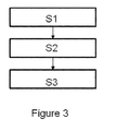
- the figure 3 illustrates a method according to another aspect of the present invention.
- receiving an energy request from at least one of said plurality of ECUs at step S2, determining the priority of the received energy request from at least one of said plurality of ECUs, at step S3, managing supply of energy depending on said determined priority of said energy request from at least one of said plurality of ECUs.
- energy management system can be a single ECU which has information about all the energy resources and are managed centrally based on the energy request.
Landscapes
- Engineering & Computer Science (AREA)
- Chemical & Material Sciences (AREA)
- Combustion & Propulsion (AREA)
- Transportation (AREA)
- Mechanical Engineering (AREA)
- Automation & Control Theory (AREA)
- Electric Propulsion And Braking For Vehicles (AREA)
- Charge And Discharge Circuits For Batteries Or The Like (AREA)
- Remote Monitoring And Control Of Power-Distribution Networks (AREA)
Abstract
Description
- The following specification describes and ascertains the nature of this invention and the manner in which it is to be performed:
- This invention relates to an energy management system in a vehicle and a method for managing the energy requirement in a vehicle.
- There are prior art which discloses Energy management systems that are commonly used in those applications (for ex. buildings) where a relatively large number of stations (hotel rooms) at separate locations which have individual energy requirements are managed by a central controller. In such systems, each station reports to the controller the current conditions at the station and the controller determines the energy requirements for that station and transmits information to that station to control a local energy, system at that station to bring the current condition to a desired condition. The prior art
WO1988008586A1 discloses such a system. - The present invention is described with reference to the following accompanying drawing:
-
Figure 1 illustrates an energy management system in accordance with one embodiment of the present invention; - The
figure 2 is an example illustration of the invention; and - The
figure 3 illustrates a method of the present invention. -
Figure 1 illustrates an example of anenergy management system 100 in accordance with one embodiment of the present invention. - In accordance with one embodiment of the invention, the
energy management system 100 is equipped in a vehicle (not shown). The vehicle comprises plurality of Electronic Control Units (ECUs) 101,102,103, 104 for controlling vehicle operation such as engine operation, emission control, cluster control, vehicle body control, battery management and the like. Plurality ofenergy generation devices energy consumption devices unit 20 for determining priority of the received energy request from at least one of the plurality of ECUs; and amanagement unit 30 for managing supply of energy depending on the determined priority of the energy request from at least one of the plurality of ECUs. The plurality of the ECUs communicates each other via avehicle network bus 55 such as Control Area Network (CAN), FlexRay, Ethernet and the like. - The Plurality of energy resources are for example electrical energy, kinetic energy, mechanical energy, heat energy and the like. The energy is either stored or generated during the engine operation of the vehicle. The electrical energy for example is a stored energy in a battery or generated using alternator during engine operation.
- The energy management system defines the energy priority rules that are stored in each ECUs. Each energy resources are given the priority and this priority is also stored in the ECUs. The energy consumption devices may be connected with one or more energy resources for its operation and are controlled via plurality of energy distributing/routing channels C1, C2, C3, C4, C5. The routing channels may contain one or more controlling means 250, 260, 270 which are controlled by respective ECU's. Each ECU 101,102,103, 104 monitors its energy resources for determining magnitude of energy that is generated, and magnitude of energy that has been dissipated or being dissipated by energy consuming devices, duration of the energy generated and if stored the remaining energy in the resource, duration of the energy that has been distributed to other energy consuming devices for dissipation and etc.
- Whenever the energy consumption device governed by the ECU 101,102,103, 104 cannot meet its energy needs from its default/pre-decided energy resource, it can transmit an "Energy request" i.e. broadcast its energy requirement in the
vehicle network bus 55. - The energy consumption device may require additional energy for its operation and the governing ECU may request this additional energy from other energy resources to achieve its functional success. The energy request is sent on the
vehicle network bus 55 and all the ECUs may receive the request on the samevehicle network bus 55 or on a different vehicle network bus. - The energy request may include one or more of the following information but may not be limited to these:
- a) Type of the requested energy (Heat, electrical, mechanical, kinetic, etc.).
- b) Identification of the functional entity or Identification of the specific ECU initiating the energy request.
- c) Magnitude of the requested energy (for example kilo joules, kilo watts or watts etc).
- d) Time duration within which the "energy request" should be fulfilled to achieve functional success.
- Each ECU 101,102,103, 104 receives energy request by reception means 10 from at least one of the plurality of ECUs and extracts the energy request information to the
prioritize unit 20 for determining priority of the received energy request. Theenergy management unit 30 devises the energy supply strategies from the various energy resources depending on the prioritization of the energy request. Based on the priority, owner of the excess energy may respond to the requested ECU 101,102,103, 104 about its energy supply capability information. Each ECU is well aware of its own energy needs and is willing to distribute the excess energy available. - Based on pre-defined rules that are applied to the energy availability information -a decision can be taken by the
energy management unit 30 as to which resource the energy will be sourced from. The energy availability information can be suitably extracted and stored in the form of a table or any other suitable data structure for easy reference and update. Once the energy sourcing decision is made, the necessary or corresponding energy routing related actuations/valve opening or closing actions will be carried out. - The owner of the excess energy may respond to the requested ECU 101,102,103, 104 for giving the additional energy within the requested time duration. Once the energy response is confirmed, the energy is distributed to the consuming device through the respective routing channels (C1, C2, C3, C4, C5).
- The
figure 2 is an example illustration of the invention for heating an aqueous solution in a tank. The aqueous solution is injected into the exhaust gas stream to reduce various oxides of nitrogen (NOx). The aqueous solution is injected using dosing module and controlled by control unit such asexhaust control unit 101. The aqueous solution has a freezing point of -11.5 degree Celsius. When the temperature is less than or equal to -11.5 degree Celsius the aqueous solution starts to freeze and cannot be used for exhaust gas treatment. To convert frozen aqueous solution into liquid, theaqueous tank 41 is fitted with anelectrical heat element 3 or anexhaust heat element 2. - The
electrical heat element 3 is heated electrically by supplying electrical energy from the electrical energy resource like battery. The energy from the battery is managed by abattery management unit 103. Electrical supply to theelectrical heat element 3 is controlled through an electrical control means 260. The battery may be further connected to other electrical energy consumption devices such as air cooler, music system and the electronic control units and the like. Thebattery management unit 103 monitors the battery for determining the remaining energy in the battery and controlling the energy to other energy consumption devices based on the priority of the energy requirement. - Further, the aqueous solution can be heated by passing an exhaust heat to the
exhaust heat element 2. The exhaust heat is supplied to thesupply conduit 7a to heat the aqueous solution. The supply to the exhaust heat is controlled by a controlling means such ascontrol valve 240 by theexhaust control unit 101. - The
battery management unit 103 and theexhaust control unit 101 may communicate each other by avehicle network bus 55 such as CAN or Flexray. - During the starting of the vehicle, the
exhaust control unit 101 monitors theaqueous tank 41 and if frozen it sends energy request over the vehicle network bus to all the ECUs in the network. In the illustrative example the reception means 10 of thebattery management unit 103 receives the energy request from theexhaust control unit 101, theprioritize unit 20 of thebattery management unit 103 prioritizes the received energy request and theenergy management unit 30 of thebattery management unit 103 manages the supply of energy depending on the priority of the energy request. Theenergy management unit 30 of thebattery management unit 103 supplies electrical energy from the battery to heat theheat element 3 to convert frozen aqueous solution into liquid which is at higher priority according to the priority rule compared to supplying electrical energy to the other low priority energy consuming devices for example music system. - Though the
exhaust control unit 101 can utilize the exhaust heat from theheat energy resource 40, due to non availability of the exhaust heat during starting of the engine, it requires other energy resource which is capable of heating the aqueous solution. In the illustrative example, the tank is fitted only with two energy resources and highest priority to heat the aqueous solution is by electrical means during starting of the engine and to maintain the aqueous solution in the liquid from being freezing is by exhaust heat during vehicle operation. - The
figure 3 illustrates a method according to another aspect of the present invention. At step S1, receiving an energy request from at least one of said plurality of ECUs, at step S2, determining the priority of the received energy request from at least one of said plurality of ECUs, at step S3, managing supply of energy depending on said determined priority of said energy request from at least one of said plurality of ECUs. - It must be understood that the embodiments explained in the above detailed description in only illustrative and does not limit the scope of this invention. The scope of this invention is limited only by the scope of the claims. Many modification and changes in the embodiments aforementioned are envisaged and are within the scope of this invention. For example energy management system can be a single ECU which has information about all the energy resources and are managed centrally based on the energy request.
Claims (6)
- An energy management system (100) in a vehicle, said vehicle comprising plurality of electronic control units (101,102,103, 104) (ECUs) for controlling energy supply, said energy management system (100) comprising:- a reception means (10) for receiving an energy request from at least one of said plurality of ECUs (101,102,103, 104);- a prioritize unit (20) for determining priority of the received energy request; and- an energy management unit (30) for managing supply of energy depending on said determined priority of said received energy request from at least one of said plurality of ECUs (101,102,103, 104).
- The energy management system (100) according to the claim 1, wherein plurality of energy resources (40, 50, 60, 70) are controlled by said ECUs (101, 102, 103, 104).
- An energy management system (100) according to the claim 1, wherein said plurality of energy resources are heat energy, electrical energy, kinetic energy, mechanical energy and etc.
- A method in a vehicle, said vehicle comprising plurality of Electronic Control Units (ECUs) (101,102,103, 104) for controlling energy supply, said method characterized in- receiving (S1) an energy request from at least one of said plurality of ECUs (101,102,103, 104);- determining (S2) priority of the received energy request from at least one of said plurality of ECUs (101,102,103, 104); and- managing (S3) supply of energy depending on said priority of said energy request from at least one of said plurality of ECUs (101,102,103, 104).
- The method according to the claim 4, wherein said energy is heat energy, electrical energy, kinetic energy and mechanical energy.
- The method according to one of the preceding claim, wherein said energy request comprises type of the energy, identification of the energy requester, magnitude of the requested energy, time duration within which the energy supply is required.
Applications Claiming Priority (1)
| Application Number | Priority Date | Filing Date | Title |
|---|---|---|---|
| IN4453CH2013 IN2013CH04453A (en) | 2013-09-30 | 2013-09-30 |
Publications (3)
| Publication Number | Publication Date |
|---|---|
| EP2857270A2 true EP2857270A2 (en) | 2015-04-08 |
| EP2857270A3 EP2857270A3 (en) | 2015-07-08 |
| EP2857270B1 EP2857270B1 (en) | 2020-11-25 |
Family
ID=51690205
Family Applications (1)
| Application Number | Title | Priority Date | Filing Date |
|---|---|---|---|
| EP14185879.5A Active EP2857270B1 (en) | 2013-09-30 | 2014-09-23 | Energy management system in a vehicle and a method thereof |
Country Status (2)
| Country | Link |
|---|---|
| EP (1) | EP2857270B1 (en) |
| IN (1) | IN2013CH04453A (en) |
Cited By (2)
| Publication number | Priority date | Publication date | Assignee | Title |
|---|---|---|---|---|
| EP3095657A1 (en) * | 2015-05-19 | 2016-11-23 | MAN Truck & Bus AG | Method for controlling power flows in a motor vehicle |
| CN111566369A (en) * | 2018-01-18 | 2020-08-21 | 舍弗勒技术股份两合公司 | Method for operating a bearing having at least a first energy supply module and a second energy supply module |
Citations (1)
| Publication number | Priority date | Publication date | Assignee | Title |
|---|---|---|---|---|
| WO1988008586A1 (en) | 1987-04-21 | 1988-11-03 | Magnavox Government And Industrial Electronics Com | Energy management control apparatus |
Family Cites Families (3)
| Publication number | Priority date | Publication date | Assignee | Title |
|---|---|---|---|---|
| DE19709317B4 (en) * | 1997-03-07 | 2008-04-30 | Robert Bosch Gmbh | Method and device for controlling a vehicle |
| DE10334535A1 (en) * | 2003-07-29 | 2005-02-17 | Robert Bosch Gmbh | Information transmitter prioritization method for automobile coordinated drive train control uses linear prioritization for transmitter selection |
| DE102006026404A1 (en) * | 2006-06-07 | 2007-12-13 | Robert Bosch Gmbh | Energy coordinator for an electrical network |
-
2013
- 2013-09-30 IN IN4453CH2013 patent/IN2013CH04453A/en unknown
-
2014
- 2014-09-23 EP EP14185879.5A patent/EP2857270B1/en active Active
Patent Citations (1)
| Publication number | Priority date | Publication date | Assignee | Title |
|---|---|---|---|---|
| WO1988008586A1 (en) | 1987-04-21 | 1988-11-03 | Magnavox Government And Industrial Electronics Com | Energy management control apparatus |
Cited By (2)
| Publication number | Priority date | Publication date | Assignee | Title |
|---|---|---|---|---|
| EP3095657A1 (en) * | 2015-05-19 | 2016-11-23 | MAN Truck & Bus AG | Method for controlling power flows in a motor vehicle |
| CN111566369A (en) * | 2018-01-18 | 2020-08-21 | 舍弗勒技术股份两合公司 | Method for operating a bearing having at least a first energy supply module and a second energy supply module |
Also Published As
| Publication number | Publication date |
|---|---|
| EP2857270B1 (en) | 2020-11-25 |
| IN2013CH04453A (en) | 2015-04-03 |
| EP2857270A3 (en) | 2015-07-08 |
Similar Documents
| Publication | Publication Date | Title |
|---|---|---|
| US11138310B2 (en) | Communication system and method for nodes associated with a vehicle | |
| US10516965B2 (en) | HVAC control using geofencing | |
| KR101299301B1 (en) | Method and system for scheduling periodic processes | |
| EP3404800B1 (en) | Multi-regulator power supply chip with common control bus | |
| CN107223183B (en) | Power management system for wind turbines connected to power sources having limited capacity | |
| US20100332647A1 (en) | Method and system of updating presence information in a communication system | |
| US10206015B2 (en) | System and method for vehicle data communication | |
| WO2012001513A3 (en) | System and method for generating and updating pcc rules based on service requests | |
| WO2018121349A1 (en) | Can bus control method and communication system using can bus | |
| EP2857270A2 (en) | Energy management system in a vehicle and a method thereof | |
| CN113778463A (en) | Business service deployment method and device | |
| CN103869768A (en) | Monitoring systems of a vehicle by generating and transmitting customized information messages to wireless networked computers | |
| US11196294B2 (en) | Power management method, power management server, local control apparatus, and power management system | |
| JP6884545B2 (en) | Communication method, central control device and individual control device | |
| Kong et al. | Optimal scheduling for unmanned aerial vehicle networks with flow-level dynamics | |
| CN116853152A (en) | Timing management system and timing management method for electric automobile | |
| JP2018085720A (en) | Improving bandwidth on deterministic aircraft data networks | |
| KR101419558B1 (en) | Monitoring system of plc system and monitoring method of plc system using the same | |
| KR102113641B1 (en) | Packet scheduling method by using mixed-criticality mode in software-defined network system, computer program therefor, and switch apparatus therefor | |
| Xie et al. | A DAG-based secure cooperative task offloading scheme in vehicular networks | |
| US9860191B2 (en) | Method for constructing optimal time-controlled paths in a large computer network | |
| CN101546200A (en) | Method, system and computer for realizing temperature control | |
| CN114006931B (en) | Networking control method and device for unit, computer equipment and storage medium | |
| Cui et al. | Research in building automation system simulation based on network control | |
| CN116599913A (en) | Data stream scheduling method and device, electronic equipment and storage medium |
Legal Events
| Date | Code | Title | Description |
|---|---|---|---|
| PUAI | Public reference made under article 153(3) epc to a published international application that has entered the european phase |
Free format text: ORIGINAL CODE: 0009012 |
|
| 17P | Request for examination filed |
Effective date: 20140923 |
|
| AK | Designated contracting states |
Kind code of ref document: A2 Designated state(s): AL AT BE BG CH CY CZ DE DK EE ES FI FR GB GR HR HU IE IS IT LI LT LU LV MC MK MT NL NO PL PT RO RS SE SI SK SM TR |
|
| AX | Request for extension of the european patent |
Extension state: BA ME |
|
| PUAL | Search report despatched |
Free format text: ORIGINAL CODE: 0009013 |
|
| AK | Designated contracting states |
Kind code of ref document: A3 Designated state(s): AL AT BE BG CH CY CZ DE DK EE ES FI FR GB GR HR HU IE IS IT LI LT LU LV MC MK MT NL NO PL PT RO RS SE SI SK SM TR |
|
| AX | Request for extension of the european patent |
Extension state: BA ME |
|
| RIC1 | Information provided on ipc code assigned before grant |
Ipc: B60W 20/00 20060101ALI20150602BHEP Ipc: B60W 50/00 20060101ALN20150602BHEP Ipc: B60W 10/06 20060101ALI20150602BHEP Ipc: B60W 10/08 20060101ALI20150602BHEP Ipc: B60W 10/30 20060101AFI20150602BHEP |
|
| R17P | Request for examination filed (corrected) |
Effective date: 20160108 |
|
| RBV | Designated contracting states (corrected) |
Designated state(s): AL AT BE BG CH CY CZ DE DK EE ES FI FR GB GR HR HU IE IS IT LI LT LU LV MC MK MT NL NO PL PT RO RS SE SI SK SM TR |
|
| STAA | Information on the status of an ep patent application or granted ep patent |
Free format text: STATUS: EXAMINATION IS IN PROGRESS |
|
| 17Q | First examination report despatched |
Effective date: 20180625 |
|
| RAP1 | Party data changed (applicant data changed or rights of an application transferred) |
Owner name: ROBERT BOSCH ENGINEERING AND BUSINESS SOLUTIONS LIMITED Owner name: ROBERT BOSCH GMBH |
|
| RIC1 | Information provided on ipc code assigned before grant |
Ipc: B60W 10/30 20060101AFI20200512BHEP Ipc: B60W 10/06 20060101ALI20200512BHEP Ipc: B60W 50/00 20060101ALN20200512BHEP Ipc: B60W 20/00 20160101ALI20200512BHEP Ipc: B60W 10/08 20060101ALI20200512BHEP |
|
| RIC1 | Information provided on ipc code assigned before grant |
Ipc: B60W 10/08 20060101ALI20200519BHEP Ipc: B60W 10/06 20060101ALI20200519BHEP Ipc: B60W 20/00 20160101ALI20200519BHEP Ipc: B60W 50/00 20060101ALN20200519BHEP Ipc: B60W 10/30 20060101AFI20200519BHEP |
|
| GRAP | Despatch of communication of intention to grant a patent |
Free format text: ORIGINAL CODE: EPIDOSNIGR1 |
|
| STAA | Information on the status of an ep patent application or granted ep patent |
Free format text: STATUS: GRANT OF PATENT IS INTENDED |
|
| RIC1 | Information provided on ipc code assigned before grant |
Ipc: B60W 50/00 20060101ALN20200603BHEP Ipc: B60W 10/06 20060101ALI20200603BHEP Ipc: B60W 10/08 20060101ALI20200603BHEP Ipc: B60W 10/30 20060101AFI20200603BHEP Ipc: B60W 20/00 20160101ALI20200603BHEP |
|
| INTG | Intention to grant announced |
Effective date: 20200629 |
|
| RIN1 | Information on inventor provided before grant (corrected) |
Inventor name: VADAGAVE, SANGAMESH |
|
| GRAS | Grant fee paid |
Free format text: ORIGINAL CODE: EPIDOSNIGR3 |
|
| GRAA | (expected) grant |
Free format text: ORIGINAL CODE: 0009210 |
|
| STAA | Information on the status of an ep patent application or granted ep patent |
Free format text: STATUS: THE PATENT HAS BEEN GRANTED |
|
| AK | Designated contracting states |
Kind code of ref document: B1 Designated state(s): AL AT BE BG CH CY CZ DE DK EE ES FI FR GB GR HR HU IE IS IT LI LT LU LV MC MK MT NL NO PL PT RO RS SE SI SK SM TR |
|
| REG | Reference to a national code |
Ref country code: GB Ref legal event code: FG4D |
|
| REG | Reference to a national code |
Ref country code: CH Ref legal event code: EP |
|
| REG | Reference to a national code |
Ref country code: DE Ref legal event code: R096 Ref document number: 602014072635 Country of ref document: DE |
|
| REG | Reference to a national code |
Ref country code: AT Ref legal event code: REF Ref document number: 1337944 Country of ref document: AT Kind code of ref document: T Effective date: 20201215 |
|
| REG | Reference to a national code |
Ref country code: IE Ref legal event code: FG4D |
|
| REG | Reference to a national code |
Ref country code: AT Ref legal event code: MK05 Ref document number: 1337944 Country of ref document: AT Kind code of ref document: T Effective date: 20201125 |
|
| REG | Reference to a national code |
Ref country code: NL Ref legal event code: MP Effective date: 20201125 |
|
| PG25 | Lapsed in a contracting state [announced via postgrant information from national office to epo] |
Ref country code: GR Free format text: LAPSE BECAUSE OF FAILURE TO SUBMIT A TRANSLATION OF THE DESCRIPTION OR TO PAY THE FEE WITHIN THE PRESCRIBED TIME-LIMIT Effective date: 20210226 Ref country code: PT Free format text: LAPSE BECAUSE OF FAILURE TO SUBMIT A TRANSLATION OF THE DESCRIPTION OR TO PAY THE FEE WITHIN THE PRESCRIBED TIME-LIMIT Effective date: 20210325 Ref country code: NO Free format text: LAPSE BECAUSE OF FAILURE TO SUBMIT A TRANSLATION OF THE DESCRIPTION OR TO PAY THE FEE WITHIN THE PRESCRIBED TIME-LIMIT Effective date: 20210225 Ref country code: RS Free format text: LAPSE BECAUSE OF FAILURE TO SUBMIT A TRANSLATION OF THE DESCRIPTION OR TO PAY THE FEE WITHIN THE PRESCRIBED TIME-LIMIT Effective date: 20201125 Ref country code: FI Free format text: LAPSE BECAUSE OF FAILURE TO SUBMIT A TRANSLATION OF THE DESCRIPTION OR TO PAY THE FEE WITHIN THE PRESCRIBED TIME-LIMIT Effective date: 20201125 |
|
| PG25 | Lapsed in a contracting state [announced via postgrant information from national office to epo] |
Ref country code: BG Free format text: LAPSE BECAUSE OF FAILURE TO SUBMIT A TRANSLATION OF THE DESCRIPTION OR TO PAY THE FEE WITHIN THE PRESCRIBED TIME-LIMIT Effective date: 20210225 Ref country code: AT Free format text: LAPSE BECAUSE OF FAILURE TO SUBMIT A TRANSLATION OF THE DESCRIPTION OR TO PAY THE FEE WITHIN THE PRESCRIBED TIME-LIMIT Effective date: 20201125 Ref country code: LV Free format text: LAPSE BECAUSE OF FAILURE TO SUBMIT A TRANSLATION OF THE DESCRIPTION OR TO PAY THE FEE WITHIN THE PRESCRIBED TIME-LIMIT Effective date: 20201125 Ref country code: IS Free format text: LAPSE BECAUSE OF FAILURE TO SUBMIT A TRANSLATION OF THE DESCRIPTION OR TO PAY THE FEE WITHIN THE PRESCRIBED TIME-LIMIT Effective date: 20210325 Ref country code: PL Free format text: LAPSE BECAUSE OF FAILURE TO SUBMIT A TRANSLATION OF THE DESCRIPTION OR TO PAY THE FEE WITHIN THE PRESCRIBED TIME-LIMIT Effective date: 20201125 Ref country code: SE Free format text: LAPSE BECAUSE OF FAILURE TO SUBMIT A TRANSLATION OF THE DESCRIPTION OR TO PAY THE FEE WITHIN THE PRESCRIBED TIME-LIMIT Effective date: 20201125 |
|
| REG | Reference to a national code |
Ref country code: LT Ref legal event code: MG9D |
|
| PG25 | Lapsed in a contracting state [announced via postgrant information from national office to epo] |
Ref country code: HR Free format text: LAPSE BECAUSE OF FAILURE TO SUBMIT A TRANSLATION OF THE DESCRIPTION OR TO PAY THE FEE WITHIN THE PRESCRIBED TIME-LIMIT Effective date: 20201125 |
|
| PG25 | Lapsed in a contracting state [announced via postgrant information from national office to epo] |
Ref country code: CZ Free format text: LAPSE BECAUSE OF FAILURE TO SUBMIT A TRANSLATION OF THE DESCRIPTION OR TO PAY THE FEE WITHIN THE PRESCRIBED TIME-LIMIT Effective date: 20201125 Ref country code: EE Free format text: LAPSE BECAUSE OF FAILURE TO SUBMIT A TRANSLATION OF THE DESCRIPTION OR TO PAY THE FEE WITHIN THE PRESCRIBED TIME-LIMIT Effective date: 20201125 Ref country code: SM Free format text: LAPSE BECAUSE OF FAILURE TO SUBMIT A TRANSLATION OF THE DESCRIPTION OR TO PAY THE FEE WITHIN THE PRESCRIBED TIME-LIMIT Effective date: 20201125 Ref country code: LT Free format text: LAPSE BECAUSE OF FAILURE TO SUBMIT A TRANSLATION OF THE DESCRIPTION OR TO PAY THE FEE WITHIN THE PRESCRIBED TIME-LIMIT Effective date: 20201125 Ref country code: SK Free format text: LAPSE BECAUSE OF FAILURE TO SUBMIT A TRANSLATION OF THE DESCRIPTION OR TO PAY THE FEE WITHIN THE PRESCRIBED TIME-LIMIT Effective date: 20201125 Ref country code: RO Free format text: LAPSE BECAUSE OF FAILURE TO SUBMIT A TRANSLATION OF THE DESCRIPTION OR TO PAY THE FEE WITHIN THE PRESCRIBED TIME-LIMIT Effective date: 20201125 |
|
| REG | Reference to a national code |
Ref country code: DE Ref legal event code: R097 Ref document number: 602014072635 Country of ref document: DE |
|
| PG25 | Lapsed in a contracting state [announced via postgrant information from national office to epo] |
Ref country code: DK Free format text: LAPSE BECAUSE OF FAILURE TO SUBMIT A TRANSLATION OF THE DESCRIPTION OR TO PAY THE FEE WITHIN THE PRESCRIBED TIME-LIMIT Effective date: 20201125 |
|
| PLBE | No opposition filed within time limit |
Free format text: ORIGINAL CODE: 0009261 |
|
| STAA | Information on the status of an ep patent application or granted ep patent |
Free format text: STATUS: NO OPPOSITION FILED WITHIN TIME LIMIT |
|
| PG25 | Lapsed in a contracting state [announced via postgrant information from national office to epo] |
Ref country code: NL Free format text: LAPSE BECAUSE OF FAILURE TO SUBMIT A TRANSLATION OF THE DESCRIPTION OR TO PAY THE FEE WITHIN THE PRESCRIBED TIME-LIMIT Effective date: 20201125 Ref country code: AL Free format text: LAPSE BECAUSE OF FAILURE TO SUBMIT A TRANSLATION OF THE DESCRIPTION OR TO PAY THE FEE WITHIN THE PRESCRIBED TIME-LIMIT Effective date: 20201125 Ref country code: IT Free format text: LAPSE BECAUSE OF FAILURE TO SUBMIT A TRANSLATION OF THE DESCRIPTION OR TO PAY THE FEE WITHIN THE PRESCRIBED TIME-LIMIT Effective date: 20201125 |
|
| 26N | No opposition filed |
Effective date: 20210826 |
|
| PG25 | Lapsed in a contracting state [announced via postgrant information from national office to epo] |
Ref country code: ES Free format text: LAPSE BECAUSE OF FAILURE TO SUBMIT A TRANSLATION OF THE DESCRIPTION OR TO PAY THE FEE WITHIN THE PRESCRIBED TIME-LIMIT Effective date: 20201125 Ref country code: SI Free format text: LAPSE BECAUSE OF FAILURE TO SUBMIT A TRANSLATION OF THE DESCRIPTION OR TO PAY THE FEE WITHIN THE PRESCRIBED TIME-LIMIT Effective date: 20201125 |
|
| REG | Reference to a national code |
Ref country code: CH Ref legal event code: PL |
|
| REG | Reference to a national code |
Ref country code: BE Ref legal event code: MM Effective date: 20210930 |
|
| GBPC | Gb: european patent ceased through non-payment of renewal fee |
Effective date: 20210923 |
|
| PG25 | Lapsed in a contracting state [announced via postgrant information from national office to epo] |
Ref country code: IS Free format text: LAPSE BECAUSE OF FAILURE TO SUBMIT A TRANSLATION OF THE DESCRIPTION OR TO PAY THE FEE WITHIN THE PRESCRIBED TIME-LIMIT Effective date: 20210325 Ref country code: MC Free format text: LAPSE BECAUSE OF FAILURE TO SUBMIT A TRANSLATION OF THE DESCRIPTION OR TO PAY THE FEE WITHIN THE PRESCRIBED TIME-LIMIT Effective date: 20201125 |
|
| PG25 | Lapsed in a contracting state [announced via postgrant information from national office to epo] |
Ref country code: LU Free format text: LAPSE BECAUSE OF NON-PAYMENT OF DUE FEES Effective date: 20210923 Ref country code: IE Free format text: LAPSE BECAUSE OF NON-PAYMENT OF DUE FEES Effective date: 20210923 Ref country code: GB Free format text: LAPSE BECAUSE OF NON-PAYMENT OF DUE FEES Effective date: 20210923 Ref country code: FR Free format text: LAPSE BECAUSE OF NON-PAYMENT OF DUE FEES Effective date: 20210930 Ref country code: BE Free format text: LAPSE BECAUSE OF NON-PAYMENT OF DUE FEES Effective date: 20210930 |
|
| PG25 | Lapsed in a contracting state [announced via postgrant information from national office to epo] |
Ref country code: LI Free format text: LAPSE BECAUSE OF NON-PAYMENT OF DUE FEES Effective date: 20210930 Ref country code: CH Free format text: LAPSE BECAUSE OF NON-PAYMENT OF DUE FEES Effective date: 20210930 |
|
| PG25 | Lapsed in a contracting state [announced via postgrant information from national office to epo] |
Ref country code: HU Free format text: LAPSE BECAUSE OF FAILURE TO SUBMIT A TRANSLATION OF THE DESCRIPTION OR TO PAY THE FEE WITHIN THE PRESCRIBED TIME-LIMIT; INVALID AB INITIO Effective date: 20140923 |
|
| PG25 | Lapsed in a contracting state [announced via postgrant information from national office to epo] |
Ref country code: CY Free format text: LAPSE BECAUSE OF FAILURE TO SUBMIT A TRANSLATION OF THE DESCRIPTION OR TO PAY THE FEE WITHIN THE PRESCRIBED TIME-LIMIT Effective date: 20201125 |
|
| PGFP | Annual fee paid to national office [announced via postgrant information from national office to epo] |
Ref country code: DE Payment date: 20231124 Year of fee payment: 10 |
|
| PG25 | Lapsed in a contracting state [announced via postgrant information from national office to epo] |
Ref country code: MK Free format text: LAPSE BECAUSE OF FAILURE TO SUBMIT A TRANSLATION OF THE DESCRIPTION OR TO PAY THE FEE WITHIN THE PRESCRIBED TIME-LIMIT Effective date: 20201125 |