EP2857235A1 - Vehicle suspension device - Google Patents
Vehicle suspension device Download PDFInfo
- Publication number
- EP2857235A1 EP2857235A1 EP13796492.0A EP13796492A EP2857235A1 EP 2857235 A1 EP2857235 A1 EP 2857235A1 EP 13796492 A EP13796492 A EP 13796492A EP 2857235 A1 EP2857235 A1 EP 2857235A1
- Authority
- EP
- European Patent Office
- Prior art keywords
- spring
- spring seat
- suspension device
- absorber
- support member
- Prior art date
- Legal status (The legal status is an assumption and is not a legal conclusion. Google has not performed a legal analysis and makes no representation as to the accuracy of the status listed.)
- Granted
Links
Images

Classifications
-
- B—PERFORMING OPERATIONS; TRANSPORTING
- B60—VEHICLES IN GENERAL
- B60G—VEHICLE SUSPENSION ARRANGEMENTS
- B60G15/00—Resilient suspensions characterised by arrangement, location or type of combined spring and vibration damper, e.g. telescopic type
- B60G15/02—Resilient suspensions characterised by arrangement, location or type of combined spring and vibration damper, e.g. telescopic type having mechanical spring
- B60G15/06—Resilient suspensions characterised by arrangement, location or type of combined spring and vibration damper, e.g. telescopic type having mechanical spring and fluid damper
-
- B—PERFORMING OPERATIONS; TRANSPORTING
- B60—VEHICLES IN GENERAL
- B60G—VEHICLE SUSPENSION ARRANGEMENTS
- B60G15/00—Resilient suspensions characterised by arrangement, location or type of combined spring and vibration damper, e.g. telescopic type
- B60G15/02—Resilient suspensions characterised by arrangement, location or type of combined spring and vibration damper, e.g. telescopic type having mechanical spring
- B60G15/06—Resilient suspensions characterised by arrangement, location or type of combined spring and vibration damper, e.g. telescopic type having mechanical spring and fluid damper
- B60G15/062—Resilient suspensions characterised by arrangement, location or type of combined spring and vibration damper, e.g. telescopic type having mechanical spring and fluid damper the spring being arranged around the damper
- B60G15/063—Resilient suspensions characterised by arrangement, location or type of combined spring and vibration damper, e.g. telescopic type having mechanical spring and fluid damper the spring being arranged around the damper characterised by the mounting of the spring on the damper
-
- F—MECHANICAL ENGINEERING; LIGHTING; HEATING; WEAPONS; BLASTING
- F16—ENGINEERING ELEMENTS AND UNITS; GENERAL MEASURES FOR PRODUCING AND MAINTAINING EFFECTIVE FUNCTIONING OF MACHINES OR INSTALLATIONS; THERMAL INSULATION IN GENERAL
- F16F—SPRINGS; SHOCK-ABSORBERS; MEANS FOR DAMPING VIBRATION
- F16F1/00—Springs
- F16F1/02—Springs made of steel or other material having low internal friction; Wound, torsion, leaf, cup, ring or the like springs, the material of the spring not being relevant
- F16F1/04—Wound springs
- F16F1/12—Attachments or mountings
- F16F1/126—Attachments or mountings comprising an element between the end coil of the spring and the support proper, e.g. an elastomeric annulus
-
- F—MECHANICAL ENGINEERING; LIGHTING; HEATING; WEAPONS; BLASTING
- F16—ENGINEERING ELEMENTS AND UNITS; GENERAL MEASURES FOR PRODUCING AND MAINTAINING EFFECTIVE FUNCTIONING OF MACHINES OR INSTALLATIONS; THERMAL INSULATION IN GENERAL
- F16F—SPRINGS; SHOCK-ABSORBERS; MEANS FOR DAMPING VIBRATION
- F16F9/00—Springs, vibration-dampers, shock-absorbers, or similarly-constructed movement-dampers using a fluid or the equivalent as damping medium
- F16F9/32—Details
-
- B—PERFORMING OPERATIONS; TRANSPORTING
- B60—VEHICLES IN GENERAL
- B60G—VEHICLE SUSPENSION ARRANGEMENTS
- B60G2202/00—Indexing codes relating to the type of spring, damper or actuator
- B60G2202/30—Spring/Damper and/or actuator Units
- B60G2202/32—The spring being in series with the damper and/or actuator
-
- B—PERFORMING OPERATIONS; TRANSPORTING
- B60—VEHICLES IN GENERAL
- B60G—VEHICLE SUSPENSION ARRANGEMENTS
- B60G2204/00—Indexing codes related to suspensions per se or to auxiliary parts
- B60G2204/10—Mounting of suspension elements
-
- B—PERFORMING OPERATIONS; TRANSPORTING
- B60—VEHICLES IN GENERAL
- B60G—VEHICLE SUSPENSION ARRANGEMENTS
- B60G2204/00—Indexing codes related to suspensions per se or to auxiliary parts
- B60G2204/10—Mounting of suspension elements
- B60G2204/12—Mounting of springs or dampers
- B60G2204/124—Mounting of coil springs
- B60G2204/1242—Mounting of coil springs on a damper, e.g. MacPerson strut
Definitions
- the present invention relates to a vehicle suspension device, and more particularly, to a strut-type suspension device including a spring.
- a strut-type suspension device has such a structure that a spring-integrated shock absorber including, in combination, a spring and an outer cylinder having an absorber built therein and a lower arm are coupled to a knuckle, thereby supporting a wheel.
- JP 2003-326932 A there is disclosed a technology of arranging a center axis of the spring so as to be inclined with respect to a center axis of an absorber for the purpose of obtaining a load axis of the spring that can withstand a bending stress applied to an absorber rod generated due to vehicle weight or received from a road surface. According to the above-mentioned structure, driving comfort of a vehicle can be enhanced.
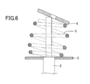
- the center axis of the spring is inclined with respect to the center axis of the absorber, and hence an upper end turn portion of the spring is inclined during assembly. Therefore, for example, as illustrated in FIG. 6 , an upper support 4 is inclined during assembly of the upper support 4, with the result that easiness of assembly is deteriorated.
- the present invention has been made in view of the above-mentioned problem, and has an object to enhance easiness of assembly in a vehicle suspension device of such a type that a load axis of a spring may be inclined with respect to a center axis of an absorber.
- a vehicle suspension device including: an absorber; an outer cylinder having the absorber built therein; a coil spring arranged coaxially with the absorber, the coil spring including end turn portions at both ends thereof and a spring portion between the end turn portions; a spring seat on which the coil spring is mounted, the spring seat being provided on an outer circumference of the outer cylinder; and an upper support for holding the coil spring between the upper support and the spring seat.
- a support member is formed in a region between the spring seat and the spring portion. The support member is configured to support the spring portion with respect to the spring seat during assembly. The support member is prevented from supporting the spring portion with respect to the spring seat during a usage state.
- the description "prevented from supporting” herein encompasses a state in which, when another member is provided in the region between the spring seat and the spring portion so as to be held in contact with each other, the supporting force is reduced as compared to that during assembly.
- a vehicle suspension device including: an absorber; an outer cylinder having the absorber built therein; a coil spring arranged coaxially with the absorber, the coil spring including end turn portions at both ends thereof and a spring portion between the end turn portions; a spring seat on which the coil spring is mounted, the spring seat being provided on an outer circumference of the outer cylinder; and an upper support for holding the coil spring between the upper support and the spring seat.
- a support member is formed in a region between the spring seat and the spring portion. The support member is formed so as to be held in contact with each of the spring portion and the spring seat during assembly. The support member is configured to secure a clearance between the spring portion and the spring seat during a usage state.
- the support member is formed so as to be held in contact with only one of the spring portion and the spring seat while avoiding contact with the other of the spring portion and the spring seat.
- the entire shape of the support member during the usage state is different from that during assembly. In other words, the support member during the usage state is deformed as compared to the shape during assembly.
- a number of turns of one of the end turn portions of the coil spring on the spring seat side is less than one.
- the support member is formed between the spring seat and a "part of the spring portion corresponding to a region, in which the end turn portions on the spring seat side is absent," when the coil spring is viewed from the spring seat side along a center axis of the coil spring.
- the coil spring is arranged coaxially with the absorber.
- the support member supports, with respect to the spring seat, the spring portion (part of the spring portion corresponding to the region, in which the one of the end turn portions on the spring seat side is absent).
- a "full contact state" described later can be obtained. Accordingly, the state in which the center axis of the coil spring and the center axis of the absorber are substantially aligned with each other can be stably ensured. Therefore, during assembly, the upper support becomes substantially parallel to a ground surface, with the result that the assembly work is facilitated.
- the support member does not support, with respect to the spring seat, the spring portion (part of the spring portion corresponding to the region, in which the one of the end turn portions on the spring seat side is absent).
- a "partial contact state” described later can be obtained.
- the load axis of the coil spring can be inclined with respect to the center axis of the absorber while maintaining the state in which the coil spring is arranged coaxially with the absorber (state in which the center axis of the coil spring is arranged coaxially with the center axis of the absorber). According to the present invention described above, it is possible to enhance the easiness of assembly in the vehicle suspension device of such a type that the load axis of the spring may be inclined with respect to the center axis of the absorber.
- the support member includes a mount interposed between one of the end turn portions and the spring seat. According to the above-mentioned structure, during the usage state, a load that the spring seat receives from the end turn portions of the spring is distributed.
- the support member have a projection portion formed thereon, and the spring seat have a hole formed therein so as to be opposed to the projection portion.
- the projection portion is fitted into the hole. Therefore, after the compression, that is, after the assembly, the misalignment of the coil spring or the support member with respect to the spring seat can be suppressed.
- the support member include a plastically deformable member. According to the above-mentioned structure, during assembly, it is unnecessary to adjust a position of the coil spring or the mount with respect to the spring seat.
- a suspension device 1 is provided inside a wheelhouse, and is connected to a wheel 200 through intermediation of a knuckle 100.
- a lower arm 300 is connected to the wheel 200.
- the suspension device 1 is interposed between the wheel 200 and a vehicle body, with the result that vibration caused due to driving can be effectively reduced.
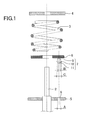
- FIG. 1 illustrates a state before assembly according to the present invention.
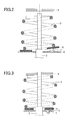
- FIG. 2 illustrates a state during assembly according to the present invention.
- FIG. 3 illustrates a "usage state” according to the present invention, and this state is realized through the "assembly" as illustrated in FIG. 2 .
- the suspension device 1 of this embodiment includes an absorber 2, a spring 3, an upper support 4, a spring seat 5, a mount 6, and a support section 7.
- the absorber 2 is, for example, a hydraulic shock absorber.
- the spring 3 is, for example, a coil spring made of metal.
- the spring 3 that functions as a spring includes a spring portion that functions as a spring and end turn portions.
- the end turn portion refers to flat portions at both ends of the spring, which do not function as a spring. In this case, it suffices that the number of turns of the end turn portion of the spring 3 on the spring seat 5 side be less than one, and in this embodiment, the number of turns thereof is one half or less.
- the upper support 4 and the spring seat 5 are, for example, made of metal, and are substantially flat plates having a doughnut shape. As illustrated in FIG. 3 , during the usage state, the upper support 4 is held in contact with the end turn portion of the spring 3.
- the spring seat 5 is welded and joined to an outer cylinder of the absorber 2, and is held in contact with the end turn portion of the spring 3 through intermediation of the mount 6 described below. That is, the spring 3 is held between the upper support 4 and the spring seat 5.
- the spring seat 5 has a hole 8 having a diameter A.
- the mount 6 is, for example, made of resin, and is a substantially flat plate having a doughnut shape.
- the mount 6 is interposed between the spring 3 and the spring seat 5, and is held in contact with the end turn portion of the spring 3.
- the mount 6 mitigates an impact applied to the spring seat 5 when the spring 3 contracts.
- the support section 7 is integrally formed on the mount 6 at a position opposed to the hole 8.
- the support section 7 is made of rubber, resin, or the like.
- the mount 6 and the support section 7 correspond to a support member in the present invention.
- the support section 7 includes a head portion 11 having a diameter B, a plate member 10 having a diameter C, and a shaft portion 9.
- the diameter B of the head portion 11 is smaller than the diameter A of the hole 8 of the spring seat, and the diameter C of the plate member 10 is larger than the diameter A of the hole 8. Therefore, the head portion 11 is inserted into the hole 8 during assembly, and thus the plate member 10 engages with an edge portion of the hole 8.
- the number of turns of the end turn portion on the spring seat 5 side is less than one.
- an end portion of the spring 3 on the spring seat 5 side has two regions when the coil spring 3 is viewed from the spring seat 5 side along the center axis thereof. Specifically, there are formed a region in which the end turn portion is present (range in a circumferential direction), and a region in which the end turn portion is absent (range in the circumferential direction). Accordingly, as illustrated in FIG. 3 , during the usage state, a contact surface of the spring 3 with the spring seat 5 (more specifically, the mount 6) is only part corresponding to the end turn portion.
- a part of the mount 6 is lifted by the support section 7 from the spring seat 5.
- the mount 6 is also held in contact with a part of the spring 3 other than the end turn portion, that is, a "part of the spring portion corresponding to the region, in which the end turn portion on the spring seat side is absent, when the coil spring 3 is viewed from the spring seat 5 side along the center axis thereof".
- the end portion of the spring 3 on the spring seat 5 side is held in contact with the mount 6 not only in the region in which the end turn portion is present but also in the region in which the end turn portion is absent, when the coil spring 3 is viewed from the spring seat 5 side along the center axis thereof.
- the “full contact state” encompasses a state in which the end turn portion and the mount 6 are held in surface contact with each other in a case where the number of turns of the end turn portion on the spring seat 5 side is one or more (that is, in a case where the end turn portion is present at the end portion of the spring 3 on the spring seat 5 side over the entire region in the circumferential direction, when the coil spring 3 is viewed from the spring seat 5 side along the center axis thereof).
- a load axis of the spring 3 is significantly inclined with respect to the center axis of the absorber 2 as compared to the "full contact state".
- the suspension device 1 is downsized as compared to that when the center axis of the spring 3 is offset in order to incline the load axis, with the result that a space in the wheelhouse can be reduced.
- the support section 7 and the hole 8 opposed to the support section 7 are formed.
- the plate member 10 is caught on the hole 8, with the result that the "full contact state" is realized between the mount 6 and the spring 3.
- the head portion 11 of the support section 7 serves for positioning of the support section 7 with respect to the hole 8.
- the shaft portion 9 of the support section 7 is fitted into the hole 8. Therefore, the misalignment of the mount 6 with respect to the spring seat 5 can be suppressed.
- the support section 7 may be formed in a region between the mount 6 and the spring 3. Further, the mount may be omitted in a region between the spring seat 5 and the spring 3. In this case, during assembly, the support section 7 supports the spring portion of the spring 3. According to the above-mentioned structure, the number of components can be reduced, with the result that the cost can be reduced.
- the plate member 10 of the support section 7 may have a tapered shape.
- the support section 7 may have such a structure that, during assembly, the plate member 10 is not deformed by the weight of the spring 3 itself without passing through the hole 8 (the shaft portion 9 is not fitted into the hole 8), but the plate member 10 is deformed by a compression load during assembly of the upper support to pass through the hole 8 (the shaft portion 9 is fitted into the hole 8).
- a plurality of support sections 7 and a plurality of holes 8 may be formed.
- the support section 7 may be integrally formed on the mount 6.
- the support section 7 may be formed of a plastically deformable member.
- the support section 7 is held in contact with (supports) the mount 6 (the spring 3 when the mount 6 is not provided), and during the usage state, the support section 7 is not held in contact with (does not support) the mount 6 (the spring 3 when the mount 6 is not provided). That is, the support section 7 is plastically deformed by a predetermined compression load applied thereto so that the support section 7 is smaller in height during the usage state than during assembly. For example, during the usage state, the support section 7 may be crushed. According to the above-mentioned structure, it is unnecessary to form the hole 8 in the spring seat 5 or the mount 6, with the result that the work of positioning the hole 8 and the support section 7 so as to be opposed to each other becomes unnecessary.
Landscapes
- Engineering & Computer Science (AREA)
- Mechanical Engineering (AREA)
- General Engineering & Computer Science (AREA)
- Vehicle Body Suspensions (AREA)
- Fluid-Damping Devices (AREA)
- Springs (AREA)
Abstract
Description
- The present invention relates to a vehicle suspension device, and more particularly, to a strut-type suspension device including a spring.
- In general, a strut-type suspension device has such a structure that a spring-integrated shock absorber including, in combination, a spring and an outer cylinder having an absorber built therein and a lower arm are coupled to a knuckle, thereby supporting a wheel.
- In
JP 2003-326932 A - Incidentally, according to the description of
JP 2003-326932 A FIG. 6 , anupper support 4 is inclined during assembly of theupper support 4, with the result that easiness of assembly is deteriorated. - The present invention has been made in view of the above-mentioned problem, and has an object to enhance easiness of assembly in a vehicle suspension device of such a type that a load axis of a spring may be inclined with respect to a center axis of an absorber.
- In order to achieve the object described above, according to one embodiment of the present invention, there is provided a vehicle suspension device, including: an absorber; an outer cylinder having the absorber built therein; a coil spring arranged coaxially with the absorber, the coil spring including end turn portions at both ends thereof and a spring portion between the end turn portions; a spring seat on which the coil spring is mounted, the spring seat being provided on an outer circumference of the outer cylinder; and an upper support for holding the coil spring between the upper support and the spring seat. In this case, a support member is formed in a region between the spring seat and the spring portion. The support member is configured to support the spring portion with respect to the spring seat during assembly. The support member is prevented from supporting the spring portion with respect to the spring seat during a usage state. The description "prevented from supporting" herein encompasses a state in which, when another member is provided in the region between the spring seat and the spring portion so as to be held in contact with each other, the supporting force is reduced as compared to that during assembly.
- Further, according to another embodiment of the present invention, there is provided a vehicle suspension device, including: an absorber; an outer cylinder having the absorber built therein; a coil spring arranged coaxially with the absorber, the coil spring including end turn portions at both ends thereof and a spring portion between the end turn portions; a spring seat on which the coil spring is mounted, the spring seat being provided on an outer circumference of the outer cylinder; and an upper support for holding the coil spring between the upper support and the spring seat. In this case, a support member is formed in a region between the spring seat and the spring portion. The support member is formed so as to be held in contact with each of the spring portion and the spring seat during assembly. The support member is configured to secure a clearance between the spring portion and the spring seat during a usage state. In this case, when another member is provided in the region between the spring portion and the spring seat, the clearance only needs to be secured between the spring portion and the spring seat. Typically, during the usage state, the support member is formed so as to be held in contact with only one of the spring portion and the spring seat while avoiding contact with the other of the spring portion and the spring seat. The entire shape of the support member during the usage state is different from that during assembly. In other words, the support member during the usage state is deformed as compared to the shape during assembly.
- Typically, in the above-mentioned vehicle suspension device, a number of turns of one of the end turn portions of the coil spring on the spring seat side is less than one. In this case, the support member is formed between the spring seat and a "part of the spring portion corresponding to a region, in which the end turn portions on the spring seat side is absent," when the coil spring is viewed from the spring seat side along a center axis of the coil spring.
- According to the above-mentioned structure, the coil spring is arranged coaxially with the absorber. In addition, during assembly, the support member supports, with respect to the spring seat, the spring portion (part of the spring portion corresponding to the region, in which the one of the end turn portions on the spring seat side is absent). In other words, a "full contact state" described later can be obtained. Accordingly, the state in which the center axis of the coil spring and the center axis of the absorber are substantially aligned with each other can be stably ensured. Therefore, during assembly, the upper support becomes substantially parallel to a ground surface, with the result that the assembly work is facilitated. Further, during the usage state, the support member does not support, with respect to the spring seat, the spring portion (part of the spring portion corresponding to the region, in which the one of the end turn portions on the spring seat side is absent). In other words, a "partial contact state" described later can be obtained. Accordingly, the load axis of the coil spring can be inclined with respect to the center axis of the absorber while maintaining the state in which the coil spring is arranged coaxially with the absorber (state in which the center axis of the coil spring is arranged coaxially with the center axis of the absorber). According to the present invention described above, it is possible to enhance the easiness of assembly in the vehicle suspension device of such a type that the load axis of the spring may be inclined with respect to the center axis of the absorber.
- In the vehicle suspension device according to the one embodiment of the present invention, the support member includes a mount interposed between one of the end turn portions and the spring seat. According to the above-mentioned structure, during the usage state, a load that the spring seat receives from the end turn portions of the spring is distributed.
- In the vehicle suspension device according to the one embodiment of the present invention, it is preferred that the support member have a projection portion formed thereon, and the spring seat have a hole formed therein so as to be opposed to the projection portion.
- According to the above-mentioned structure, for example, when a predetermined compression load is applied, the projection portion is fitted into the hole. Therefore, after the compression, that is, after the assembly, the misalignment of the coil spring or the support member with respect to the spring seat can be suppressed.
- In the vehicle suspension device according to the one embodiment of the present invention, it is preferred that the support member include a plastically deformable member. According to the above-mentioned structure, during assembly, it is unnecessary to adjust a position of the coil spring or the mount with respect to the spring seat.
-
-
FIG. 1 is a sectional view illustrating a structure of a suspension device before assembly according to an embodiment of the present invention. -
FIG. 2 is a sectional view illustrating a structure of the suspension device during assembly according to the embodiment of the present invention. -
FIG. 3 is a sectional view illustrating a structure of the suspension device after assembly (during a usage state) according to the embodiment of the present invention. -
FIG. 4 is a sectional view illustrating a structure of a suspension device according to another embodiment of the present invention. -
FIG. 5 is a view illustrating a state of assembly of a strut-type suspension device to a vehicle. -
FIG. 6 is a sectional view illustrating an inclination of an upper support during assembly of the suspension device. - Now, embodiments of the present invention are described with reference to the drawings.
- As illustrated in
FIG. 5 , asuspension device 1 is provided inside a wheelhouse, and is connected to awheel 200 through intermediation of aknuckle 100. Alower arm 300 is connected to thewheel 200. Thesuspension device 1 is interposed between thewheel 200 and a vehicle body, with the result that vibration caused due to driving can be effectively reduced. -
FIG. 1 illustrates a state before assembly according to the present invention.FIG. 2 illustrates a state during assembly according to the present invention.FIG. 3 illustrates a "usage state" according to the present invention, and this state is realized through the "assembly" as illustrated inFIG. 2 . - As illustrated in
FIG. 1 , thesuspension device 1 of this embodiment includes anabsorber 2, aspring 3, anupper support 4, aspring seat 5, amount 6, and asupport section 7. - The
absorber 2 is, for example, a hydraulic shock absorber. Thespring 3 is, for example, a coil spring made of metal. Thespring 3 that functions as a spring includes a spring portion that functions as a spring and end turn portions. The end turn portion refers to flat portions at both ends of the spring, which do not function as a spring. In this case, it suffices that the number of turns of the end turn portion of thespring 3 on thespring seat 5 side be less than one, and in this embodiment, the number of turns thereof is one half or less. - The
upper support 4 and thespring seat 5 are, for example, made of metal, and are substantially flat plates having a doughnut shape. As illustrated inFIG. 3 , during the usage state, theupper support 4 is held in contact with the end turn portion of thespring 3. Thespring seat 5 is welded and joined to an outer cylinder of theabsorber 2, and is held in contact with the end turn portion of thespring 3 through intermediation of themount 6 described below. That is, thespring 3 is held between theupper support 4 and thespring seat 5. - As illustrated in
FIG. 1 , thespring seat 5 has ahole 8 having a diameter A. - The
mount 6 is, for example, made of resin, and is a substantially flat plate having a doughnut shape. Themount 6 is interposed between thespring 3 and thespring seat 5, and is held in contact with the end turn portion of thespring 3. Themount 6 mitigates an impact applied to thespring seat 5 when thespring 3 contracts. - As illustrated in
FIG. 2 , thesupport section 7 is integrally formed on themount 6 at a position opposed to thehole 8. Thesupport section 7 is made of rubber, resin, or the like. Note that, themount 6 and thesupport section 7 correspond to a support member in the present invention. Thesupport section 7 includes ahead portion 11 having a diameter B, aplate member 10 having a diameter C, and ashaft portion 9. In this case, the diameter B of thehead portion 11 is smaller than the diameter A of thehole 8 of the spring seat, and the diameter C of theplate member 10 is larger than the diameter A of thehole 8. Therefore, thehead portion 11 is inserted into thehole 8 during assembly, and thus theplate member 10 engages with an edge portion of thehole 8. - In the assembly state as illustrated in
FIG. 2 , a predetermined compression load is applied to theupper support 4, and thus theplate member 10 is deformed and passes through thehole 8. With this, as illustrated inFIG. 3 , theshaft portion 9 is inserted into thehole 8, and thus thesupport section 7 and thehole 8 are fitted to each other. - In this embodiment, as described above, the number of turns of the end turn portion on the
spring seat 5 side is less than one. In other words, an end portion of thespring 3 on thespring seat 5 side has two regions when thecoil spring 3 is viewed from thespring seat 5 side along the center axis thereof. Specifically, there are formed a region in which the end turn portion is present (range in a circumferential direction), and a region in which the end turn portion is absent (range in the circumferential direction). Accordingly, as illustrated inFIG. 3 , during the usage state, a contact surface of thespring 3 with the spring seat 5 (more specifically, the mount 6) is only part corresponding to the end turn portion. That is, the end portion of thespring 3 on thespring seat 5 side is held in contact with themount 6 only in the region in which the end turn portion is present and is not held in contact with themount 6 in the region in which the end turn portion is absent, when thecoil spring 3 is viewed from thespring seat 5 side along the center axis thereof. This state is hereinafter referred to as a "partial contact state". - Further, during assembly, as illustrated in
FIG. 2 , a part of themount 6 is lifted by thesupport section 7 from thespring seat 5. As a result, themount 6 is also held in contact with a part of thespring 3 other than the end turn portion, that is, a "part of the spring portion corresponding to the region, in which the end turn portion on the spring seat side is absent, when thecoil spring 3 is viewed from thespring seat 5 side along the center axis thereof". More specifically, the end portion of thespring 3 on thespring seat 5 side is held in contact with themount 6 not only in the region in which the end turn portion is present but also in the region in which the end turn portion is absent, when thecoil spring 3 is viewed from thespring seat 5 side along the center axis thereof. This state is hereinafter referred to as a "full contact state". Note that, the "full contact state" encompasses a state in which the end turn portion and themount 6 are held in surface contact with each other in a case where the number of turns of the end turn portion on thespring seat 5 side is one or more (that is, in a case where the end turn portion is present at the end portion of thespring 3 on thespring seat 5 side over the entire region in the circumferential direction, when thecoil spring 3 is viewed from thespring seat 5 side along the center axis thereof). - According to the above-mentioned structure, when the
spring 3 and themount 6 are in the "partial contact state", a load axis of thespring 3 is significantly inclined with respect to the center axis of theabsorber 2 as compared to the "full contact state". With this, it is possible to obtain such a load axis of the spring that can withstand a bending stress applied to an absorber rod, which is generated due to vehicle weight or received from a road surface, with the result that thespring 3 can suppress the bending stress that the suspension receives due to the vehicle weight or from the road surface. Further, thesuspension device 1 is downsized as compared to that when the center axis of thespring 3 is offset in order to incline the load axis, with the result that a space in the wheelhouse can be reduced. - In this embodiment, as described above, the
support section 7 and thehole 8 opposed to thesupport section 7 are formed. According to the above-mentioned structure, as illustrated inFIG. 2 , when thespring 3 is mounted on thespring seat 5 during assembly, theplate member 10 is caught on thehole 8, with the result that the "full contact state" is realized between themount 6 and thespring 3. Accordingly, the state in which the center axis of thecoil spring 3 and the center axis of theabsorber 2 are substantially aligned with each other can be stably ensured. Therefore, during assembly, theupper support 4 becomes substantially parallel to a ground surface, with the result that the assembly work is facilitated. In this case, thehead portion 11 of thesupport section 7 serves for positioning of thesupport section 7 with respect to thehole 8. Further, during the usage state, as illustrated inFIG. 3 , theshaft portion 9 of thesupport section 7 is fitted into thehole 8. Therefore, the misalignment of themount 6 with respect to thespring seat 5 can be suppressed. - The present invention is not limited to the above-mentioned embodiment, and for example, the
support section 7 may be formed in a region between themount 6 and thespring 3. Further, the mount may be omitted in a region between thespring seat 5 and thespring 3. In this case, during assembly, thesupport section 7 supports the spring portion of thespring 3. According to the above-mentioned structure, the number of components can be reduced, with the result that the cost can be reduced. - The present invention is not limited to the above-mentioned embodiment, and for example, as illustrated in
FIG. 4 , theplate member 10 of thesupport section 7 may have a tapered shape. In short, thesupport section 7 may have such a structure that, during assembly, theplate member 10 is not deformed by the weight of thespring 3 itself without passing through the hole 8 (theshaft portion 9 is not fitted into the hole 8), but theplate member 10 is deformed by a compression load during assembly of the upper support to pass through the hole 8 (theshaft portion 9 is fitted into the hole 8). Note that, a plurality ofsupport sections 7 and a plurality ofholes 8 may be formed. - Further, for example, as illustrated in
FIG. 4 , thesupport section 7 may be integrally formed on themount 6. - Further, the
support section 7 may be formed of a plastically deformable member. In this case, during assembly, thesupport section 7 is held in contact with (supports) the mount 6 (thespring 3 when themount 6 is not provided), and during the usage state, thesupport section 7 is not held in contact with (does not support) the mount 6 (thespring 3 when themount 6 is not provided). That is, thesupport section 7 is plastically deformed by a predetermined compression load applied thereto so that thesupport section 7 is smaller in height during the usage state than during assembly. For example, during the usage state, thesupport section 7 may be crushed. According to the above-mentioned structure, it is unnecessary to form thehole 8 in thespring seat 5 or themount 6, with the result that the work of positioning thehole 8 and thesupport section 7 so as to be opposed to each other becomes unnecessary.
Claims (6)
- A vehicle suspension device, comprising:an absorber;an outer cylinder having the absorber built therein;a coil spring arranged coaxially with the absorber, the coil spring comprising end turn portions at both ends thereof and a spring portion between the end turn portions;a spring seat on which the coil spring is mounted, the spring seat being provided on an outer circumference of the outer cylinder;an upper support for holding the coil spring between the upper support and the spring seat; anda support member formed in a region between the spring seat and the spring portion,the support member being configured to support the spring portion with respect to the spring seat during assembly,the support member being prevented from supporting the spring portion with respect to the spring seat during a usage state.
- A vehicle suspension device, comprising:an absorber;an outer cylinder having the absorber built therein;a coil spring arranged coaxially with the absorber, the coil spring comprising end turn portions at both ends thereof and a spring portion between the end turn portions;a spring seat on which the coil spring is mounted, the spring seat being provided on an outer circumference of the outer cylinder;an upper support for holding the coil spring between the upper support and the spring seat; anda support member formed in a region between the spring seat and the spring portion,the support member being formed so as to be held in contact with each of the spring portion and the spring seat during assembly,the support member being configured to secure a clearance between the spring portion and the spring seat during a usage state.
- A vehicle suspension device according to claim 1 or 2, wherein the support member comprises a mount interposed between one of the end turn portions and the spring seat.
- A vehicle suspension device according to any one of claims 1 to 3,
wherein the support member has a projection portion formed thereon, and
wherein the spring seat has a hole formed therein so as to be opposed to the projection portion. - A vehicle suspension device according to any one of claims 1 to 3, wherein the support member comprises a plastically deformable member.
- A vehicle suspension device according to any one of claims 1 to 5,
wherein a number of turns of one of the end turn portions of the coil spring on the spring seat side is less than one, and
wherein the support member is formed between the spring seat and a part of the spring portion corresponding to a region, in which the one of the end turn portions on the spring seat side is absent, when the coil spring is viewed from the spring seat side along a center axis of the coil spring.
Applications Claiming Priority (2)
| Application Number | Priority Date | Filing Date | Title |
|---|---|---|---|
| JP2012125771 | 2012-06-01 | ||
| PCT/JP2013/053471 WO2013179692A1 (en) | 2012-06-01 | 2013-02-14 | Vehicle suspension device |
Publications (4)
| Publication Number | Publication Date |
|---|---|
| EP2857235A1 true EP2857235A1 (en) | 2015-04-08 |
| EP2857235A4 EP2857235A4 (en) | 2016-01-20 |
| EP2857235B1 EP2857235B1 (en) | 2020-03-25 |
| EP2857235B8 EP2857235B8 (en) | 2020-04-29 |
Family
ID=49672908
Family Applications (1)
| Application Number | Title | Priority Date | Filing Date |
|---|---|---|---|
| EP13796492.0A Active EP2857235B8 (en) | 2012-06-01 | 2013-02-14 | Vehicle suspension device |
Country Status (5)
| Country | Link |
|---|---|
| US (1) | US9399381B2 (en) |
| EP (1) | EP2857235B8 (en) |
| JP (1) | JP5915738B2 (en) |
| CN (1) | CN104364097B (en) |
| WO (1) | WO2013179692A1 (en) |
Families Citing this family (7)
| Publication number | Priority date | Publication date | Assignee | Title |
|---|---|---|---|---|
| US9802454B2 (en) | 2014-07-28 | 2017-10-31 | Tenneco Automotive Operating Company Inc. | Plastic spring seat having integrated crash member |
| JP6434750B2 (en) * | 2014-09-04 | 2018-12-05 | 株式会社ショーワ | Spring seat |
| JP6482212B2 (en) * | 2014-09-04 | 2019-03-13 | 株式会社ショーワ | Spring seat |
| JP6613095B2 (en) * | 2015-10-01 | 2019-11-27 | 日本発條株式会社 | Coil spring for suspension |
| US9873303B2 (en) * | 2016-03-22 | 2018-01-23 | Tenneco Automotive Operating Company Inc. | Damper having reinforced catcher |
| JP6367257B2 (en) * | 2016-04-13 | 2018-08-01 | サンコール株式会社 | Coil spring |
| CN110130764B (en) * | 2019-06-19 | 2024-06-14 | 广东东箭汽车科技股份有限公司 | Electric tail gate balance bar, electric tail gate balance structure and electric tail gate |
Family Cites Families (23)
| Publication number | Priority date | Publication date | Assignee | Title |
|---|---|---|---|---|
| US3069149A (en) * | 1960-05-31 | 1962-12-18 | Gen Motors Corp | Coil spring suspension with auxiliary overload bumper |
| US3954255A (en) * | 1974-08-30 | 1976-05-04 | Monroe Belgium N. V. | Suspension strut |
| JPS5844210U (en) * | 1981-08-19 | 1983-03-24 | 富士重工業株式会社 | Automotive strut type wheel suspension system |
| DE3730177A1 (en) * | 1987-09-09 | 1989-03-30 | Bayerische Motoren Werke Ag | Spring strut for motor vehicles |
| FR2637338B1 (en) * | 1988-10-04 | 1994-03-25 | Allevard Industries Sa | SUPPORT CUP FOR VEHICLE SUSPENSION SPRING AND VEHICLE SUSPENSION COMPRISING SUCH A CUP |
| JPH03121915A (en) * | 1989-10-03 | 1991-05-23 | Nhk Spring Co Ltd | Suspension device for vehicle |
| FR2768659A1 (en) * | 1997-09-24 | 1999-03-26 | Caoutchouc Manuf Plastique | Suspension assembly for vehicle wheel |
| JP4275230B2 (en) * | 1998-12-18 | 2009-06-10 | プレス工業株式会社 | Coil spring fixing device, coil spring unit, and sliding door opening / closing auxiliary device and suspension device using the same |
| JP4011252B2 (en) * | 2000-02-18 | 2007-11-21 | カヤバ工業株式会社 | Mounting method of suspension spring in hydraulic shock absorber |
| JP2001330071A (en) * | 2000-05-23 | 2001-11-30 | Fuji Heavy Ind Ltd | Spring seat structure |
| WO2002058949A1 (en) * | 2001-01-23 | 2002-08-01 | Societe De Technologie Michelin | Suspension device of a motor vehicle wheel |
| JP3801947B2 (en) | 2001-05-29 | 2006-07-26 | 三菱製鋼株式会社 | Spring seat |
| JP2003326932A (en) | 2002-05-09 | 2003-11-19 | Nok Corp | Strut type suspension |
| US6883790B2 (en) * | 2002-11-06 | 2005-04-26 | Arvinmeritor Technology, Llc | Coil spring with lateral bias |
| JP4378983B2 (en) | 2003-03-25 | 2009-12-09 | オイレス工業株式会社 | Strut plain bearing |
| JP2005240923A (en) * | 2004-02-26 | 2005-09-08 | Showa Corp | Front forks such as motorcycles |
| JP4597723B2 (en) | 2004-12-16 | 2010-12-15 | 株式会社ショーワ | Spring seat structure of hydraulic shock absorber |
| DE102005050023A1 (en) * | 2005-10-19 | 2007-05-03 | Zf Friedrichshafen Ag | Method for mounting coil spring on spring seat, involves supporting coil spring on radial guide face whereby coil spring is aligned on spring seat and radial guide face is formed by shape alterable material |
| US20070158925A1 (en) * | 2006-01-06 | 2007-07-12 | Fader Joseph A | Static pierce point centering spring seat |
| DE102006010054B4 (en) * | 2006-03-04 | 2014-08-28 | Bayerische Motoren Werke Aktiengesellschaft | Wheel suspension with spring adjustment for a motor vehicle |
| JP2008089151A (en) * | 2006-10-04 | 2008-04-17 | Nissan Motor Co Ltd | Shock absorber |
| JP5200945B2 (en) | 2009-01-13 | 2013-06-05 | マツダ株式会社 | Car suspension equipment |
| JP5222260B2 (en) * | 2009-09-18 | 2013-06-26 | 本田技研工業株式会社 | Elastic support member |
-
2013
- 2013-02-14 US US14/404,871 patent/US9399381B2/en not_active Expired - Fee Related
- 2013-02-14 CN CN201380029032.8A patent/CN104364097B/en not_active Expired - Fee Related
- 2013-02-14 EP EP13796492.0A patent/EP2857235B8/en active Active
- 2013-02-14 JP JP2014518300A patent/JP5915738B2/en not_active Expired - Fee Related
- 2013-02-14 WO PCT/JP2013/053471 patent/WO2013179692A1/en not_active Ceased
Also Published As
| Publication number | Publication date |
|---|---|
| CN104364097A (en) | 2015-02-18 |
| CN104364097B (en) | 2017-07-18 |
| US9399381B2 (en) | 2016-07-26 |
| EP2857235A4 (en) | 2016-01-20 |
| US20150123329A1 (en) | 2015-05-07 |
| EP2857235B1 (en) | 2020-03-25 |
| JP5915738B2 (en) | 2016-05-11 |
| JPWO2013179692A1 (en) | 2016-01-18 |
| EP2857235B8 (en) | 2020-04-29 |
| WO2013179692A1 (en) | 2013-12-05 |
Similar Documents
| Publication | Publication Date | Title |
|---|---|---|
| EP2857235B1 (en) | Vehicle suspension device | |
| US8899602B2 (en) | Vehicle suspension support structure | |
| KR101427079B1 (en) | Lower arm for vehicle suspension system | |
| EP2809532B1 (en) | Vehicle suspension comprising light weight leaf spring assembly | |
| CN105377594B (en) | Vehicle suspension and its leaf spring | |
| EP2783884B1 (en) | Suspension device and suspension support | |
| KR20130079312A (en) | Strut assembly having multi-piece spring seat | |
| JP2000072036A (en) | Automotive suspension system | |
| US6616160B2 (en) | Strut mount | |
| US8696004B2 (en) | Spring seat having an installation land/step | |
| EP1681180A1 (en) | Strut mount | |
| US20170274719A1 (en) | Damper having reinforced catcher | |
| KR20140120452A (en) | Suspension bearing modules | |
| JP5661593B2 (en) | Vehicle suspension system | |
| JP4367835B2 (en) | Suspension spring support structure for hydraulic shock absorber | |
| US8579309B1 (en) | Vehicle frame mounting | |
| JP5965274B2 (en) | Strut rod mounting structure to the vehicle body side panel | |
| JP2007309357A (en) | Air spring and suspension using the air spring | |
| JP2002347420A (en) | Upper mount mechanism for vehicle suspension system | |
| US12397601B2 (en) | Shock absorber and bracket | |
| JP2010276137A (en) | Strut mount | |
| JP2007276661A (en) | Suspension structure | |
| JP2015044487A (en) | Mounting structure of brake hose of vehicle | |
| KR100911546B1 (en) | Suspension structure of vehicle | |
| JP2012219841A (en) | Upper support supporting structure of suspension for automobile |
Legal Events
| Date | Code | Title | Description |
|---|---|---|---|
| PUAI | Public reference made under article 153(3) epc to a published international application that has entered the european phase |
Free format text: ORIGINAL CODE: 0009012 |
|
| 17P | Request for examination filed |
Effective date: 20141208 |
|
| AK | Designated contracting states |
Kind code of ref document: A1 Designated state(s): AL AT BE BG CH CY CZ DE DK EE ES FI FR GB GR HR HU IE IS IT LI LT LU LV MC MK MT NL NO PL PT RO RS SE SI SK SM TR |
|
| AX | Request for extension of the european patent |
Extension state: BA ME |
|
| DAX | Request for extension of the european patent (deleted) | ||
| RA4 | Supplementary search report drawn up and despatched (corrected) |
Effective date: 20151223 |
|
| RIC1 | Information provided on ipc code assigned before grant |
Ipc: B60G 15/06 20060101ALI20151217BHEP Ipc: F16F 1/12 20060101ALI20151217BHEP Ipc: B60G 13/06 20060101ALI20151217BHEP Ipc: F16F 9/32 20060101ALI20151217BHEP Ipc: B60G 11/16 20060101AFI20151217BHEP Ipc: B60G 3/28 20060101ALI20151217BHEP |
|
| STAA | Information on the status of an ep patent application or granted ep patent |
Free format text: STATUS: EXAMINATION IS IN PROGRESS |
|
| 17Q | First examination report despatched |
Effective date: 20180613 |
|
| GRAP | Despatch of communication of intention to grant a patent |
Free format text: ORIGINAL CODE: EPIDOSNIGR1 |
|
| STAA | Information on the status of an ep patent application or granted ep patent |
Free format text: STATUS: GRANT OF PATENT IS INTENDED |
|
| INTG | Intention to grant announced |
Effective date: 20191007 |
|
| GRAS | Grant fee paid |
Free format text: ORIGINAL CODE: EPIDOSNIGR3 |
|
| GRAA | (expected) grant |
Free format text: ORIGINAL CODE: 0009210 |
|
| STAA | Information on the status of an ep patent application or granted ep patent |
Free format text: STATUS: THE PATENT HAS BEEN GRANTED |
|
| GRAT | Correction requested after decision to grant or after decision to maintain patent in amended form |
Free format text: ORIGINAL CODE: EPIDOSNCDEC |
|
| RAP1 | Party data changed (applicant data changed or rights of an application transferred) |
Owner name: TOYOTA JIDOSHA KABUSHIKI KAISHA |
|
| AK | Designated contracting states |
Kind code of ref document: B1 Designated state(s): AL AT BE BG CH CY CZ DE DK EE ES FI FR GB GR HR HU IE IS IT LI LT LU LV MC MK MT NL NO PL PT RO RS SE SI SK SM TR |
|
| REG | Reference to a national code |
Ref country code: DE Ref legal event code: R083 Ref document number: 602013067216 Country of ref document: DE Ref country code: GB Ref legal event code: FG4D |
|
| RIN2 | Information on inventor provided after grant (corrected) |
Inventor name: TOYOTA, SATORU |
|
| REG | Reference to a national code |
Ref country code: AT Ref legal event code: REF Ref document number: 1248175 Country of ref document: AT Kind code of ref document: T Effective date: 20200415 Ref country code: CH Ref legal event code: PK Free format text: BERICHTIGUNG B8 Ref country code: IE Ref legal event code: FG4D |
|
| REG | Reference to a national code |
Ref country code: DE Ref legal event code: R096 Ref document number: 602013067216 Country of ref document: DE |
|
| PG25 | Lapsed in a contracting state [announced via postgrant information from national office to epo] |
Ref country code: NO Free format text: LAPSE BECAUSE OF FAILURE TO SUBMIT A TRANSLATION OF THE DESCRIPTION OR TO PAY THE FEE WITHIN THE PRESCRIBED TIME-LIMIT Effective date: 20200625 Ref country code: RS Free format text: LAPSE BECAUSE OF FAILURE TO SUBMIT A TRANSLATION OF THE DESCRIPTION OR TO PAY THE FEE WITHIN THE PRESCRIBED TIME-LIMIT Effective date: 20200325 Ref country code: FI Free format text: LAPSE BECAUSE OF FAILURE TO SUBMIT A TRANSLATION OF THE DESCRIPTION OR TO PAY THE FEE WITHIN THE PRESCRIBED TIME-LIMIT Effective date: 20200325 |
|
| PG25 | Lapsed in a contracting state [announced via postgrant information from national office to epo] |
Ref country code: SE Free format text: LAPSE BECAUSE OF FAILURE TO SUBMIT A TRANSLATION OF THE DESCRIPTION OR TO PAY THE FEE WITHIN THE PRESCRIBED TIME-LIMIT Effective date: 20200325 Ref country code: LV Free format text: LAPSE BECAUSE OF FAILURE TO SUBMIT A TRANSLATION OF THE DESCRIPTION OR TO PAY THE FEE WITHIN THE PRESCRIBED TIME-LIMIT Effective date: 20200325 Ref country code: GR Free format text: LAPSE BECAUSE OF FAILURE TO SUBMIT A TRANSLATION OF THE DESCRIPTION OR TO PAY THE FEE WITHIN THE PRESCRIBED TIME-LIMIT Effective date: 20200626 Ref country code: BG Free format text: LAPSE BECAUSE OF FAILURE TO SUBMIT A TRANSLATION OF THE DESCRIPTION OR TO PAY THE FEE WITHIN THE PRESCRIBED TIME-LIMIT Effective date: 20200625 Ref country code: HR Free format text: LAPSE BECAUSE OF FAILURE TO SUBMIT A TRANSLATION OF THE DESCRIPTION OR TO PAY THE FEE WITHIN THE PRESCRIBED TIME-LIMIT Effective date: 20200325 |
|
| REG | Reference to a national code |
Ref country code: NL Ref legal event code: MP Effective date: 20200325 |
|
| REG | Reference to a national code |
Ref country code: LT Ref legal event code: MG4D |
|
| PG25 | Lapsed in a contracting state [announced via postgrant information from national office to epo] |
Ref country code: NL Free format text: LAPSE BECAUSE OF FAILURE TO SUBMIT A TRANSLATION OF THE DESCRIPTION OR TO PAY THE FEE WITHIN THE PRESCRIBED TIME-LIMIT Effective date: 20200325 |
|
| PG25 | Lapsed in a contracting state [announced via postgrant information from national office to epo] |
Ref country code: PT Free format text: LAPSE BECAUSE OF FAILURE TO SUBMIT A TRANSLATION OF THE DESCRIPTION OR TO PAY THE FEE WITHIN THE PRESCRIBED TIME-LIMIT Effective date: 20200818 Ref country code: IS Free format text: LAPSE BECAUSE OF FAILURE TO SUBMIT A TRANSLATION OF THE DESCRIPTION OR TO PAY THE FEE WITHIN THE PRESCRIBED TIME-LIMIT Effective date: 20200725 Ref country code: SK Free format text: LAPSE BECAUSE OF FAILURE TO SUBMIT A TRANSLATION OF THE DESCRIPTION OR TO PAY THE FEE WITHIN THE PRESCRIBED TIME-LIMIT Effective date: 20200325 Ref country code: RO Free format text: LAPSE BECAUSE OF FAILURE TO SUBMIT A TRANSLATION OF THE DESCRIPTION OR TO PAY THE FEE WITHIN THE PRESCRIBED TIME-LIMIT Effective date: 20200325 Ref country code: CZ Free format text: LAPSE BECAUSE OF FAILURE TO SUBMIT A TRANSLATION OF THE DESCRIPTION OR TO PAY THE FEE WITHIN THE PRESCRIBED TIME-LIMIT Effective date: 20200325 Ref country code: SM Free format text: LAPSE BECAUSE OF FAILURE TO SUBMIT A TRANSLATION OF THE DESCRIPTION OR TO PAY THE FEE WITHIN THE PRESCRIBED TIME-LIMIT Effective date: 20200325 Ref country code: EE Free format text: LAPSE BECAUSE OF FAILURE TO SUBMIT A TRANSLATION OF THE DESCRIPTION OR TO PAY THE FEE WITHIN THE PRESCRIBED TIME-LIMIT Effective date: 20200325 Ref country code: LT Free format text: LAPSE BECAUSE OF FAILURE TO SUBMIT A TRANSLATION OF THE DESCRIPTION OR TO PAY THE FEE WITHIN THE PRESCRIBED TIME-LIMIT Effective date: 20200325 |
|
| REG | Reference to a national code |
Ref country code: AT Ref legal event code: MK05 Ref document number: 1248175 Country of ref document: AT Kind code of ref document: T Effective date: 20200325 |
|
| REG | Reference to a national code |
Ref country code: DE Ref legal event code: R097 Ref document number: 602013067216 Country of ref document: DE |
|
| PG25 | Lapsed in a contracting state [announced via postgrant information from national office to epo] |
Ref country code: ES Free format text: LAPSE BECAUSE OF FAILURE TO SUBMIT A TRANSLATION OF THE DESCRIPTION OR TO PAY THE FEE WITHIN THE PRESCRIBED TIME-LIMIT Effective date: 20200325 Ref country code: DK Free format text: LAPSE BECAUSE OF FAILURE TO SUBMIT A TRANSLATION OF THE DESCRIPTION OR TO PAY THE FEE WITHIN THE PRESCRIBED TIME-LIMIT Effective date: 20200325 Ref country code: AT Free format text: LAPSE BECAUSE OF FAILURE TO SUBMIT A TRANSLATION OF THE DESCRIPTION OR TO PAY THE FEE WITHIN THE PRESCRIBED TIME-LIMIT Effective date: 20200325 Ref country code: IT Free format text: LAPSE BECAUSE OF FAILURE TO SUBMIT A TRANSLATION OF THE DESCRIPTION OR TO PAY THE FEE WITHIN THE PRESCRIBED TIME-LIMIT Effective date: 20200325 |
|
| PLBE | No opposition filed within time limit |
Free format text: ORIGINAL CODE: 0009261 |
|
| STAA | Information on the status of an ep patent application or granted ep patent |
Free format text: STATUS: NO OPPOSITION FILED WITHIN TIME LIMIT |
|
| PG25 | Lapsed in a contracting state [announced via postgrant information from national office to epo] |
Ref country code: PL Free format text: LAPSE BECAUSE OF FAILURE TO SUBMIT A TRANSLATION OF THE DESCRIPTION OR TO PAY THE FEE WITHIN THE PRESCRIBED TIME-LIMIT Effective date: 20200325 |
|
| 26N | No opposition filed |
Effective date: 20210112 |
|
| PG25 | Lapsed in a contracting state [announced via postgrant information from national office to epo] |
Ref country code: SI Free format text: LAPSE BECAUSE OF FAILURE TO SUBMIT A TRANSLATION OF THE DESCRIPTION OR TO PAY THE FEE WITHIN THE PRESCRIBED TIME-LIMIT Effective date: 20200325 |
|
| REG | Reference to a national code |
Ref country code: DE Ref legal event code: R084 Ref document number: 602013067216 Country of ref document: DE |
|
| PG25 | Lapsed in a contracting state [announced via postgrant information from national office to epo] |
Ref country code: MC Free format text: LAPSE BECAUSE OF FAILURE TO SUBMIT A TRANSLATION OF THE DESCRIPTION OR TO PAY THE FEE WITHIN THE PRESCRIBED TIME-LIMIT Effective date: 20200325 |
|
| GBPC | Gb: european patent ceased through non-payment of renewal fee |
Effective date: 20210214 |
|
| REG | Reference to a national code |
Ref country code: BE Ref legal event code: MM Effective date: 20210228 |
|
| PG25 | Lapsed in a contracting state [announced via postgrant information from national office to epo] |
Ref country code: LI Free format text: LAPSE BECAUSE OF NON-PAYMENT OF DUE FEES Effective date: 20210228 Ref country code: LU Free format text: LAPSE BECAUSE OF NON-PAYMENT OF DUE FEES Effective date: 20210214 Ref country code: CH Free format text: LAPSE BECAUSE OF NON-PAYMENT OF DUE FEES Effective date: 20210228 |
|
| PG25 | Lapsed in a contracting state [announced via postgrant information from national office to epo] |
Ref country code: GB Free format text: LAPSE BECAUSE OF NON-PAYMENT OF DUE FEES Effective date: 20210214 Ref country code: IE Free format text: LAPSE BECAUSE OF NON-PAYMENT OF DUE FEES Effective date: 20210214 Ref country code: FR Free format text: LAPSE BECAUSE OF NON-PAYMENT OF DUE FEES Effective date: 20210228 |
|
| PGFP | Annual fee paid to national office [announced via postgrant information from national office to epo] |
Ref country code: DE Payment date: 20211230 Year of fee payment: 10 |
|
| PG25 | Lapsed in a contracting state [announced via postgrant information from national office to epo] |
Ref country code: BE Free format text: LAPSE BECAUSE OF NON-PAYMENT OF DUE FEES Effective date: 20210228 |
|
| PG25 | Lapsed in a contracting state [announced via postgrant information from national office to epo] |
Ref country code: HU Free format text: LAPSE BECAUSE OF FAILURE TO SUBMIT A TRANSLATION OF THE DESCRIPTION OR TO PAY THE FEE WITHIN THE PRESCRIBED TIME-LIMIT; INVALID AB INITIO Effective date: 20130214 |
|
| P01 | Opt-out of the competence of the unified patent court (upc) registered |
Effective date: 20230427 |
|
| PG25 | Lapsed in a contracting state [announced via postgrant information from national office to epo] |
Ref country code: CY Free format text: LAPSE BECAUSE OF FAILURE TO SUBMIT A TRANSLATION OF THE DESCRIPTION OR TO PAY THE FEE WITHIN THE PRESCRIBED TIME-LIMIT Effective date: 20200325 |
|
| REG | Reference to a national code |
Ref country code: DE Ref legal event code: R119 Ref document number: 602013067216 Country of ref document: DE |
|
| PG25 | Lapsed in a contracting state [announced via postgrant information from national office to epo] |
Ref country code: DE Free format text: LAPSE BECAUSE OF NON-PAYMENT OF DUE FEES Effective date: 20230901 |
|
| PG25 | Lapsed in a contracting state [announced via postgrant information from national office to epo] |
Ref country code: MK Free format text: LAPSE BECAUSE OF FAILURE TO SUBMIT A TRANSLATION OF THE DESCRIPTION OR TO PAY THE FEE WITHIN THE PRESCRIBED TIME-LIMIT Effective date: 20200325 |
|
| PG25 | Lapsed in a contracting state [announced via postgrant information from national office to epo] |
Ref country code: MT Free format text: LAPSE BECAUSE OF FAILURE TO SUBMIT A TRANSLATION OF THE DESCRIPTION OR TO PAY THE FEE WITHIN THE PRESCRIBED TIME-LIMIT Effective date: 20200325 |
|
| PG25 | Lapsed in a contracting state [announced via postgrant information from national office to epo] |
Ref country code: TR Free format text: LAPSE BECAUSE OF FAILURE TO SUBMIT A TRANSLATION OF THE DESCRIPTION OR TO PAY THE FEE WITHIN THE PRESCRIBED TIME-LIMIT Effective date: 20200325 |