EP2857229B1 - Battery-replacable tire pressure sensor - Google Patents
Battery-replacable tire pressure sensor Download PDFInfo
- Publication number
- EP2857229B1 EP2857229B1 EP13187499.2A EP13187499A EP2857229B1 EP 2857229 B1 EP2857229 B1 EP 2857229B1 EP 13187499 A EP13187499 A EP 13187499A EP 2857229 B1 EP2857229 B1 EP 2857229B1
- Authority
- EP
- European Patent Office
- Prior art keywords
- tire pressure
- battery
- tire
- sensing module
- sensor
- Prior art date
- Legal status (The legal status is an assumption and is not a legal conclusion. Google has not performed a legal analysis and makes no representation as to the accuracy of the status listed.)
- Not-in-force
Links
Images


Classifications
-
- B—PERFORMING OPERATIONS; TRANSPORTING
- B60—VEHICLES IN GENERAL
- B60C—VEHICLE TYRES; TYRE INFLATION; TYRE CHANGING; CONNECTING VALVES TO INFLATABLE ELASTIC BODIES IN GENERAL; DEVICES OR ARRANGEMENTS RELATED TO TYRES
- B60C23/00—Devices for measuring, signalling, controlling, or distributing tyre pressure or temperature, specially adapted for mounting on vehicles; Arrangement of tyre inflating devices on vehicles, e.g. of pumps or of tanks; Tyre cooling arrangements
- B60C23/02—Signalling devices actuated by tyre pressure
- B60C23/04—Signalling devices actuated by tyre pressure mounted on the wheel or tyre
- B60C23/0491—Constructional details of means for attaching the control device
- B60C23/0494—Valve stem attachments positioned inside the tyre chamber
-
- B—PERFORMING OPERATIONS; TRANSPORTING
- B60—VEHICLES IN GENERAL
- B60C—VEHICLE TYRES; TYRE INFLATION; TYRE CHANGING; CONNECTING VALVES TO INFLATABLE ELASTIC BODIES IN GENERAL; DEVICES OR ARRANGEMENTS RELATED TO TYRES
- B60C23/00—Devices for measuring, signalling, controlling, or distributing tyre pressure or temperature, specially adapted for mounting on vehicles; Arrangement of tyre inflating devices on vehicles, e.g. of pumps or of tanks; Tyre cooling arrangements
- B60C23/02—Signalling devices actuated by tyre pressure
- B60C23/04—Signalling devices actuated by tyre pressure mounted on the wheel or tyre
- B60C23/0408—Signalling devices actuated by tyre pressure mounted on the wheel or tyre transmitting the signals by non-mechanical means from the wheel or tyre to a vehicle body mounted receiver
- B60C23/041—Means for supplying power to the signal- transmitting means on the wheel
Definitions
- the present invention relates to a tire pressure sensor, and more particular to a tire pressure sensor with a replaceable battery structure.
- Driving safety is the primary consideration for a driver when driving and travelling on the road.
- the tire pressure is one of key factors of vehicle conditions, and has a critical influence on driving safety.
- a vehicle can run smoothly only with a normal tire pressure.
- An excessive or insufficient tire pressure may result in a punctured tire or a flat tire, which severely jeopardizes driving safety and even threatens the safety and wellbeing of passersby.
- monitoring a tire pressure for ensuring driving safety must be attended with great importance.
- a conventional method for measuring a tire pressure can only be performed for a still vehicle, and changes of the tire pressure for a driving vehicle cannot be detected in real-time. That is, a driver may not immediately learn about abnormalities in a tire during driving, and may not accordingly take appropriate actions in the event of the abnormalities.
- the Taiwan Utility Model No. M335410 discloses a "Wireless Tire Pressure Detector", as a built-in tire sensor.
- the disclosed tire pressure detector includes a sensor unit, and a gas nozzle unit integrated with the sensor unit.
- the sensor unit includes a housing, a circuit board disposed in the housing, and a gasket inserted at the housing.
- the housing has a gas intake, and a channel adjoining with the gas intake.
- the gasket is disposed at the gas intake and includes a connecting portion electrically connected to the circuit board.
- the gas nozzle unit includes a pipe member that may be utilized as an antenna, at least one washer accommodating around the pipe member, a cap screwed to one end of the pipe member, and at least one screw nut screwed to another end of the pipe member.
- a pipe member that may be utilized as an antenna
- at least one washer accommodating around the pipe member
- a cap screwed to one end of the pipe member
- at least one screw nut screwed to another end of the pipe member.
- the Taiwan Utility Model No. M405977 discloses a "Tire Pressure Sensor and Gas Nozzle Assembly".
- the disclosed structure is formed by a gas nozzle, a tire pressure sensor, and a screw bolt fastening the gas nozzle and the tire pressure sensor.
- the gas nozzle includes a connecting portion which includes an outer adjustment surface.
- the tire pressure includes a housing, which has a connecting channel connected to the connecting portion of the gas nozzle.
- the connecting channel includes an inner adjustment surface forming in a shape complementary to that of the outer adjustment surface.
- M335410 and M405977 are both built-in tire pressure sensors that are installed to the inside of a tire to detect the tire pressure.
- a high temperature is generated by friction between a tire and the ground during a driving process.
- the tire pressure sensor requires a high level of air tightness to prevent dust or moisture from entering the housing and thus affecting operations of the sensor unit. Therefore, for the above built-in tire pressure sensor, the housing is completely sealed after assembling with the sensor unit and a battery to ensure the overall air tightness. This implies that, once electrical power of the battery is depleted, the tire pressure sensor/detector of the disclosures M335410 and M405977 can no longer operate and be utilized. Even when the sensor unit is functional and undamaged, a new tire sensor needs to be purchased, which not only results in an additional cost for a driver but also produces unnecessary wastes.
- US 2002 / 046599 A1 discloses a condition sensor of pneumatic tire which is configured to be attached on a pneumatic tire of a vehicle, and the pneumatic tire has a rim with a rim bed.
- the condition sensor comprises a sensor circuit for detecting the condition of the tire, a power source for supplying the sensor circuit with electric power; and a housing having a cover portion and a base portion, in which the base portion is used to receive the sensor circuit and the power source.
- the cover portion is provided with an arc-concave surface having a convexity, in which the arc-concave surface is in arc-line contact with the rim bed and the convexity can be used to adjust the relationship position between the housing and the rim bed.
- US 2006 / 071765 A1 discloses a tire pressure monitoring device, which is disposed in a pneumatic tire and is mounted on a rim of a vehicle, including a casing, a sensor circuit, a set of electrical contacts, and a cover.
- the casing defines a battery compartment that receives a battery, and is formed with an opening to permit access in the battery compartment.
- the sensor circuit is mounted in the casing, and is operable so as to detect a pressure of the pneumatic tire, and so as to generate a signal that corresponds to the detected pressure of the pneumatic tire.
- the electrical contacts are mounted in the battery compartment of the casing, and are coupled to the sensor circuit and the battery.
- the cover is connected detachably to the casing so as to cover and uncover selectively the opening of the casing.
- the tire pressure sensor can continue to be utilized when electrical power in the tire pressure sensor runs out.
- the tire pressure sensor which can be installed to a tire rim having an assembly hole, includes a sensor body, a gas intake nozzle connected to the sensor body, and a gas nozzle assembly member coupling with the gas intake nozzle.
- the sensor body includes a tire pressure sensing module, a battery accommodating portion, a cover and a gas nozzle assembly hole.
- the tire pressure sensing module is disposed in the sensor body for detecting a tire pressure.
- the battery accommodating portion accommodates at least one battery, which supplies power to the tire pressure sensing module.
- the cover is screwed with the battery accommodating portion, and retains the battery from disengaging from the battery accommodating portion.
- the gas nozzle assembly hole is for the gas nozzle assembly member to insert therein.
- the gas intake nozzle includes a coupling section and a gas intake section.
- the coupling section is inserted into the gas nozzle assembly hole.
- the gas intake section is connected to the coupling section, and penetrates through the assembly through hole to extend towards a direction out of the tire rim for gas to input.
- the sensor body comprises a first housing and a second housing.
- the first housing includes an accommodating CN 201 287 595 Y relates to a connection structure for a tire pressure detecting sensor and a valve, which aims to guarantee the connection between the tire pressure detecting sensor and the valve to be uneasy to get loose.
- connection structure comprises a screw nail, a connecting plate, an electronic signal chest of the tire pressure detecting sensor and a valve stem, wherein the valve stem is equipped with a threaded hole and outer threads on the stem body, the screw direction of the outer threads of the valve stem is opposite to that of threads of the threaded hole of the valve stem, the connecting plate is provided with a through hole, and the electronic signal chest is provided with a boss with a threaded hole.
- valve stem extends into the threaded hole of the boss to lead the outer threads of the valve stem and the threaded hole of the boss to be engaged
- the connecting plate is arranged in the electronic signal chest
- the through hole of the connecting plate is coaxial with the threaded hole of the boss
- the screw nail penetrates through the through hole of the connecting plate to be engaged with the threaded hole of the valve stem
- the end face of the valve stem contacts with the surface of the connecting plate
- the electronic signal chest and the valve stem are connected together via the screw nail which is fixedly connected with the valve stem.
- the primary object of the present invention is to provide a built-in tire pressure sensor with a replaceable battery chamber to accommodate the tire pressure sensing module, and the second housing engages with the first housing to enclose the accommodating chamber.
- the tire pressure sensing module comprises a sensing module which includes a sensing region and saves a firmware for controlling operation of the tire pressure sensing module.
- the sensor body comprises a gas intake portion corresponding to the sensing region, and a washer disposed between the gas intake portion and the sensing region.
- the tire pressure sensing module further comprises at least one firmware update terminal disposed correspondingly to the battery accommodating portion.
- the firmware update terminal transmits update firmware data to the sensing module for updating the firmware.
- the coupling section further comprises an assembly hole facing the gas nozzle assembly hole to couple with the gas nozzle assembly member, and a positioning groove engaging with the assembly through hole to fasten the gas intake nozzle on the tire rim.
- the sensor body further includes an electromagnetic wave transmission element.
- the electromagnetic wave transmission element is electrically connected to the tire pressure sensing module to output tire condition information generated by the tire pressure sensing module after detecting the tire pressure.
- the electromagnetic wave transmission element includes a through hole.
- the through hole corresponds to the gas nozzle assembly hole for the gas nozzle assembly member to penetrate.
- the sensor body further includes a seal ring disposed between the battery accommodating portion and the cover.
- the sensor body further includes at least one support member disposed on a surface facing the tire rim.
- the support member abuts against the tire rim.
- the sensor body includes a battery accommodating portion for accommodating at least one battery, and a detachable cover screwed with the battery accommodating portion.
- the depleted battery may be replaced with a new one, so that the tire pressure sensor can continue to be utilized instead of being replaced by a new tire pressure sensor. Therefore, not only an expense for purchasing a new tire pressure sensor can be saved, but also the amount of wastes is reduced.
- a sealing ring when the cover is screwed with the battery accommodating portion, is accommodated around the battery accommodating portion and is clamped between the cover and the first housing.
- the sealing ring completely fills possible space between the cover and the battery accommodating portion, thereby further reinforcing the air tightness effect of the battery accommodating portion and preventing dust or moisture from entering the sensor body.
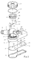
- FIGS. 1 , 2 and 5 are a schematic view, an exploded view, and a schematic view of using a battery-replaceable tire pressure sensor of the present invention.
- the battery-replaceable tire pressure sensor of the present invention may be installed on a tire rim 1 of a tire (not shown).
- the tire rim 1 includes two folded section 12 at two sides thereof to engage with a tire body (not shown), a connecting section 13 connecting the two folded sections 12, and an assembly through hole 11 disposed between one of the folded sections 12 and the connecting section 13.
- the battery-replaceable tire pressure sensor includes a sensor body 2, a gas intake nozzle 3 connected to the sensor body 2, and a gas nozzle assembly member 4 assembling the sensor body 2 with the gas intake nozzle 3.
- the sensor body 2 includes a tire pressure sensing module 23 disposed in the sensor body 2, and a battery accommodating portion 24 and a gas nozzle assembly hole 216 that are disposed at an outer surface of the sensor body 2.
- the tire pressure sensing module 23 includes a circuit board 231 and a sensing module 232 disposed on the circuit board 231.
- the sensing module 232 stores a firmware for controlling operations of the tire pressure sensing module 23, and includes a sensing region 233.
- the sensor body 2 includes a gas intake portion 215 and a washer 28.
- the gas inlet portion 215 is disposed correspondingly to the sensing region 233.
- the washer 28 is disposed correspondingly to positions of the gas intake portion 215 and the sensing region 233, and is clamped between the sensor body 2 and the tire pressure sensing module 23. After gas in the tire enters the sensor body through the gas intake portion 215, the gas is restricted by the washer 28 and then directly reaches the sensing region 233.
- the sensing module 232 detects data such as the tire temperature and tire pressure in the tire through the sensing region 233, generates correspondingly tire condition information, and transmits the tire condition information to a monitoring device (not shown) via wireless transmission.
- the monitoring device may be disposed near a driver seat for a driver to easily observe, or may be incorporated into a vehicle computer and directly displayed on a dashboard of a vehicle, so as to allow a driver to learn whether conditions of the tire are abnormal in time.
- the sensor body 2 is exemplified by a single housing.
- the sensor body 2 comprises a first housing 21, and a second housing 22 that can be engaged with the first housing 21.
- the first housing 21 includes an accommodating chamber 211, with an opening facing the connecting section 13 of the tire rim 1, for accommodating the tire pressure sensing module 23 (as shown in FIGS. 3 and 4 ).
- the accommodating chamber 211 is covered by the second housing 22 to form an enclosed space that retains the tire pressure sensing module 23 therein.
- an adhesive (not shown) may further be applied to contact parts of the second housing 22 and the first housing 21.
- dust generated from frictions of the tire or moisture is prevented from entering the accommodating chamber 211 as well as from affecting the durability of the tire sensing module 23.
- the battery accommodating portion 24 and the gas nozzle assembly hole 216 are disposed at a surface of the first housing 21 opposite the opening of the accommodating chamber 211.
- the battery accommodating portion 24 includes an outer screw thread wall 241 appearing a ring shape, and a battery recess 242 encircled by the outer screw thread wall 241 for accommodating at least one battery 25.
- the first housing 21 includes a hollow region (not shown) at a bottom part of the battery recess 241 to communicate the battery recess 241 with the accommodating chamber 211.
- the battery 25 is a lithium button battery, which is not the limitation.
- the battery may be a mercury battery, an alkaline battery or a zinc-air battery.
- the battery recess 242 includes at least one first conductor 243, a second conductor 244, and a pressure conductor 245 which are all disposed in the battery recess 242.
- the positive and negative ends of the battery 25 are respectively in contact with the pressure conductor 245 and the second conductor 244.
- the pressure conductor 245 further includes a fixing end 249, through which the pressure conductor 245 is connected to a connecting end 246 of the first conductor 243.
- the fixing end 249 may be a hook groove
- the connecting end 246 may be a hook tenon for engaging with the hook groove.
- the first housing 21 further includes a plurality of transmission holes 212 disposed at the bottom part of the battery recess 242.
- the first conductor 243 and the second conductor 244 respectively include a first conducting pin 247 and a second conducting pin 248.
- the first conducting pin 247 and the second conducting pin 248 are penetrated through the transmission holes 212 from the battery recess 242 to the accommodating chamber 211 to electrically connect to the tire pressure sensing module 23.
- the battery 25 is placed in the battery recess 242 with the negative end of the battery 25 facing the battery recess 242, such that the negative end of the battery 25 comes into contact with the second conductor 244 disposed in the battery recess 242.
- the pressure conductor 245 is then placed on the positive end of the battery 25, and the fixing end 249 is engaged with the connecting end 246 of the first conductor 243, such that the battery 25 forms an electrical connection with the tire pressure sensing module 23 via the first conducting pin 247 of the first conductor 243 and the second conducting pin 248 of the second conductor 244, as shown in FIG. 4 , thereby providing electrical power for operating the tire pressure sensing module 23.
- the sensor body 2 further includes a cover 26 corresponding to the battery accommodating portion 24.
- the cover 26 includes a screw thread inside (not shown), and is screwed with the outer screw thread wall 241 to seal the battery recess 242 of the batter accommodating portion 24, so as to retain the battery 25 therein.
- a sealing ring 27 may be additionally accommodated around the outer screw thread wall 241.
- the sealing ring 27 is clamped by the cover 26 and the first housing 21, so as to prevent moisture from entering the battery recess 242 along a gap between the outer screw thread wall 241 and the screw thread of the cover 26, thereby providing further enhanced air tightness effects.
- the tire pressure sensing module 23 further includes at least one firmware update terminal 234 located on the circuit board 231.
- the firmware stored in the sensing module 232 is configured with a predetermined condition; the predetermined condition is information (to be referred to as a safe range) such as most appropriate tire temperatures and tire pressures in normal condition of a vehicle model on which the sensor body 2 is installed. As different vehicle models may have different safe ranges, different vehicles may have different predetermined conditions.
- the tire pressure sensor is first disassembled from the old vehicle model, followed by detaching the cover 26 and the battery 25 to expose the firmware update terminal 234 through the hollow region at the lower part of the battery recess 242.
- the external electronic device is then extended into the battery recess 242 to connect to the firmware update terminal 234.
- the update firmware data is transmitted to update the firmware originally corresponding to the old vehicle model, to the firmware corresponding to the new vehicle model.
- the external electronic device may be connected to the firmware update terminal 234 via various approaches.
- the external electronic device may directly come into contact with the firmware update terminal 234 via at least one probe (not shown).
- the manufacturer may design a fixture (not shown) corresponding to an appearance of the battery accommodating portion 24, and the external electric device may be steadily connected with the firmware update terminal 24 via engaging the battery accommodating portion 24 with the fixture.
- the two examples above are for illustrative purposes, not limiting the connecting means between the firmware update terminal 234 and the external electronic device of the present invention thereto.
- the gas intake nozzle 3 may be made of a metal material, and includes a coupling section 31 corresponding to the gas nozzle assembly hole 216 and a gas intake section 32 connected to the coupling section 31.
- the coupling section 31 includes an assembly hole 311, a positioning groove 312 and an air outlet through hole 313.
- the assembly hole 311 is disposed facing the gas nozzle assembly hole 216.
- the positioning groove 312 encircles the coupling section 31 and is engaged with the assembly through hole 11 to fasten the gas intake nozzle 3 onto the tire rim 1.
- the air outlet through hole 313 is disposed between the assembly hole 311 and the positioning groove 312.
- the gas nozzle assembly hole 216 is disposed at a surface of the first housing 21 opposite to the opening of the accommodating chamber 211.
- the coupling section 31 is first inserted into the gas nozzle assembly hole 216 to contact the two with each other.
- the gas nozzle assembly member 4, facing the coupling section 31, is inserted into the gas nozzle assembly hole 216 to assemble with the assembly hole 311 of the coupling section 31, so as to steadily connect the gas intake nozzle 3 with the sensor body 2.
- the gas nozzle assembly member 4 may be a metal screw, and the assembly hole 311 includes a screw thread corresponding to the screw.
- the connection method for the gas nozzle assembly member 4 and the assembly hole 311 is not limited to the above approach.
- the gas intake section 32 penetrates through the assembly through hole 11 of the tire rim 1 to extend to the outside the tire rim1, and is thus capable of receiving an inflation gas outputted from an inflation device (not shown).
- the inflation gas passes through the gas intake nozzle 3 and flows from the air outlet through hole 313 inside the tire rim 1 to complete an inflation process.
- the sensor body 2 further includes an electromagnetic wave transmission element 29 which may be made of metals.
- the electromagnetic wave transmission element 29 is disposed on the first housing 21, connected to the gas nozzle assembly hole 216, and includes a through hole 291 corresponding to the gas nozzle assembly hole 216 and a transmission pin 292.
- the first housing 21 at a bottom part of the accommodating chamber 211, the first housing 21 further includes a transmission opening 213 corresponding to a position of the transmission pin 292.
- the transmission pin 292 may then penetrate through the transmission opening 213 to extend into the accommodating chamber 211 and to further connect to the circuit board 231.
- the electromagnetic wave transmission element 29 is electrically connected to the tire pressure sensing module 23.
- the gas nozzle assembly member 4 penetrates through the through hole 291 of the electromagnetic wave transmission element 29 and the gas nozzle assembly hole 216 to screw and fasten with the assembly hole 311, such that the electromagnetic wave transmission element 29 is clamped between the gas nozzle assembly member 4 and the gas nozzle assembly hole 216 (as shown in FIG. 3 ).
- the tire pressure sensing module 23 may electrically connect to the gas intake nozzle 3 via the electromagnetic wave transmission element 29 and the gas nozzle assembly member 4.
- the gas intake nozzle 3 may serve as an antenna for wireless transmission to transmit the tire condition information outputted by the sensing module 232 to the monitoring device.
- gas intake section 32 of the gas intake nozzle 3 is exposed to the outside of the tire rim 1 and thus has less obstruction on wireless transmission paths thereof, improved transmission effects may be achieved. Further, an adhesive (not shown) may be applied to a contact part of the transmission opening 213 and the transmission pin 292 to achieve even better sealing effects.
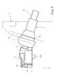
- FIG. 5 shows a schematic view of the battery-replaceable tire pressure sensor of the present invention when in use.
- the gas intake section 32 of the gas intake nozzle 3 is inserted into the assembly through hole 11, and the positioning groove 312 of the coupling section 31 is engaged onto the tire rim 1, to make the gas intake nozzle 31 be steadily fastened on the tire rim 1 at all times.
- the sensor body 2 is connected to the gas intake nozzle 3, and the gas nozzle assembly member 4 penetrates into the gas nozzle assembly hole 216 to assemble the sensor body 2 with the intake gas nozzle 3.
- the first housing 21 includes at least one support member 214 disposed on a surface facing the connecting section 13 and extending towards the connecting section 13. Instead of directly touching the connecting section 13 and thus receiving drastic vibrations of the tire rim 1, the sensor body 2 is abutted on the connecting section 13 via the support member 214, thereby preventing part damages caused by the vibrations as well as providing a buffering effect.
- the sensor body includes a battery accommodating portion and a cover.
- the battery accommodating portion is for accommodating at least one battery, and the cover is screwed with the battery accommodating portion and for retaining the battery therein.
- the depleted battery may be replaced with a new one, so that the tire pressure sensor can continue to be utilized instead of being replaced by a new tire pressure sensor. Therefore, not only an expense for purchasing a new tire pressure sensor can be saved, but also the amount of wastes is reduced.
- a sealing ring is disposed on the battery accommodating portion and is clamped between the cover and the first housing when the cover is screwed with the battery accommodating portion.
- the sealing ring completely fills possible space between the cover and the battery accommodating portion, thereby further improves the air tightness of the battery accommodating portion and preventing dust or moisture damaging electronic components in the sensor body.
Description
- The present invention relates to a tire pressure sensor, and more particular to a tire pressure sensor with a replaceable battery structure.
- Driving safety is the primary consideration for a driver when driving and travelling on the road. The tire pressure is one of key factors of vehicle conditions, and has a critical influence on driving safety. A vehicle can run smoothly only with a normal tire pressure. An excessive or insufficient tire pressure may result in a punctured tire or a flat tire, which severely jeopardizes driving safety and even threatens the safety and wellbeing of passersby. Needless to say, monitoring a tire pressure for ensuring driving safety must be attended with great importance. A conventional method for measuring a tire pressure can only be performed for a still vehicle, and changes of the tire pressure for a driving vehicle cannot be detected in real-time. That is, a driver may not immediately learn about abnormalities in a tire during driving, and may not accordingly take appropriate actions in the event of the abnormalities.
- To better and more conveniently detect a tire pressure, various tire pressure detection devices, which can be installed to a tire, have been developed by associated manufacturers to enable a driver to learn about the changes of the tire pressure in real-time. The
Taiwan Utility Model No. M335410 - The
Taiwan Utility Model No. M405977 - The above disclosures of
M335410 andM405977 are both built-in tire pressure sensors that are installed to the inside of a tire to detect the tire pressure. A high temperature is generated by friction between a tire and the ground during a driving process. Under such high-temperature and high-pressure harsh operating environment in the tire, the tire pressure sensor requires a high level of air tightness to prevent dust or moisture from entering the housing and thus affecting operations of the sensor unit. Therefore, for the above built-in tire pressure sensor, the housing is completely sealed after assembling with the sensor unit and a battery to ensure the overall air tightness. This implies that, once electrical power of the battery is depleted, the tire pressure sensor/detector of the disclosuresM335410 andM405977 can no longer operate and be utilized. Even when the sensor unit is functional and undamaged, a new tire sensor needs to be purchased, which not only results in an additional cost for a driver but also produces unnecessary wastes. -
US 2002 / 046599 A1 discloses a condition sensor of pneumatic tire which is configured to be attached on a pneumatic tire of a vehicle, and the pneumatic tire has a rim with a rim bed. The condition sensor comprises a sensor circuit for detecting the condition of the tire, a power source for supplying the sensor circuit with electric power; and a housing having a cover portion and a base portion, in which the base portion is used to receive the sensor circuit and the power source. The cover portion is provided with an arc-concave surface having a convexity, in which the arc-concave surface is in arc-line contact with the rim bed and the convexity can be used to adjust the relationship position between the housing and the rim bed. -
US 2006 / 071765 A1 discloses a tire pressure monitoring device, which is disposed in a pneumatic tire and is mounted on a rim of a vehicle, including a casing, a sensor circuit, a set of electrical contacts, and a cover. The casing defines a battery compartment that receives a battery, and is formed with an opening to permit access in the battery compartment. The sensor circuit is mounted in the casing, and is operable so as to detect a pressure of the pneumatic tire, and so as to generate a signal that corresponds to the detected pressure of the pneumatic tire. The electrical contacts are mounted in the battery compartment of the casing, and are coupled to the sensor circuit and the battery. The cover is connected detachably to the casing so as to cover and uncover selectively the opening of the casing. - structure, so that, instead of being discarded, the tire pressure sensor can continue to be utilized when electrical power in the tire pressure sensor runs out.
- To achieve the above object, a tire pressure sensor with a replaceable battery according to the features of claim 1 is provided. The tire pressure sensor, which can be installed to a tire rim having an assembly hole, includes a sensor body, a gas intake nozzle connected to the sensor body, and a gas nozzle assembly member coupling with the gas intake nozzle. The sensor body includes a tire pressure sensing module, a battery accommodating portion, a cover and a gas nozzle assembly hole. The tire pressure sensing module is disposed in the sensor body for detecting a tire pressure. The battery accommodating portion accommodates at least one battery, which supplies power to the tire pressure sensing module. The cover is screwed with the battery accommodating portion, and retains the battery from disengaging from the battery accommodating portion. The gas nozzle assembly hole is for the gas nozzle assembly member to insert therein. The gas intake nozzle includes a coupling section and a gas intake section. The coupling section is inserted into the gas nozzle assembly hole. The gas intake section is connected to the coupling section, and penetrates through the assembly through hole to extend towards a direction out of the tire rim for gas to input.
- In one embodiment, the sensor body comprises a first housing and a second housing. The first housing includes an accommodating
CN 201 287 595 Y relates to a connection structure for a tire pressure detecting sensor and a valve, which aims to guarantee the connection between the tire pressure detecting sensor and the valve to be uneasy to get loose. The connection structure comprises a screw nail, a connecting plate, an electronic signal chest of the tire pressure detecting sensor and a valve stem, wherein the valve stem is equipped with a threaded hole and outer threads on the stem body, the screw direction of the outer threads of the valve stem is opposite to that of threads of the threaded hole of the valve stem, the connecting plate is provided with a through hole, and the electronic signal chest is provided with a boss with a threaded hole. Besides, the valve stem extends into the threaded hole of the boss to lead the outer threads of the valve stem and the threaded hole of the boss to be engaged, the connecting plate is arranged in the electronic signal chest, the through hole of the connecting plate is coaxial with the threaded hole of the boss, the screw nail penetrates through the through hole of the connecting plate to be engaged with the threaded hole of the valve stem, the end face of the valve stem contacts with the surface of the connecting plate, and the electronic signal chest and the valve stem are connected together via the screw nail which is fixedly connected with the valve stem. - Therefore the primary object of the present invention is to provide a built-in tire pressure sensor with a replaceable battery chamber to accommodate the tire pressure sensing module, and the second housing engages with the first housing to enclose the accommodating chamber.
- In one embodiment, the tire pressure sensing module comprises a sensing module which includes a sensing region and saves a firmware for controlling operation of the tire pressure sensing module. Besides, the sensor body comprises a gas intake portion corresponding to the sensing region, and a washer disposed between the gas intake portion and the sensing region.
- In one embodiment, the tire pressure sensing module further comprises at least one firmware update terminal disposed correspondingly to the battery accommodating portion. The firmware update terminal transmits update firmware data to the sensing module for updating the firmware.
- In one embodiment, the coupling section further comprises an assembly hole facing the gas nozzle assembly hole to couple with the gas nozzle assembly member, and a positioning groove engaging with the assembly through hole to fasten the gas intake nozzle on the tire rim.
- In one embodiment, the sensor body further includes an electromagnetic wave transmission element. The electromagnetic wave transmission element is electrically connected to the tire pressure sensing module to output tire condition information generated by the tire pressure sensing module after detecting the tire pressure.
- In one embodiment, the electromagnetic wave transmission element includes a through hole. The through hole corresponds to the gas nozzle assembly hole for the gas nozzle assembly member to penetrate.
- In one embodiment, the sensor body further includes a seal ring disposed between the battery accommodating portion and the cover.
- In one embodiment, the sensor body further includes at least one support member disposed on a surface facing the tire rim. The support member abuts against the tire rim.
- In the present invention, the sensor body includes a battery accommodating portion for accommodating at least one battery, and a detachable cover screwed with the battery accommodating portion. Thus, when electrical power of the sensor body is depleted, the depleted battery may be replaced with a new one, so that the tire pressure sensor can continue to be utilized instead of being replaced by a new tire pressure sensor. Therefore, not only an expense for purchasing a new tire pressure sensor can be saved, but also the amount of wastes is reduced. Further, a sealing ring, when the cover is screwed with the battery accommodating portion, is accommodated around the battery accommodating portion and is clamped between the cover and the first housing. Thus, the sealing ring completely fills possible space between the cover and the battery accommodating portion, thereby further reinforcing the air tightness effect of the battery accommodating portion and preventing dust or moisture from entering the sensor body.
- The foregoing, as well as additional objects, features and advantages of the invention will be more readily apparent from the following detailed description, which proceeds with reference to the accompanying drawings.
-
-
FIG. 1 is a schematic view of a battery-replaceable tire pressure sensor according to an embodiment of the present invention; -
FIG. 2 is an exploded view of the battery-replaceable tire pressure sensor according to the embodiment of the present invention; -
FIG. 3 is a sectional view of a gas intake nozzle of the battery-replaceable tire pressure sensor according to the embodiment of the present invention; -
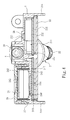
FIG. 4 is a sectional view of a sensor body of the battery-replaceable tire pressure sensor according to the embodiment of the present invention; and -
FIG. 5 is a schematic view of the battery-replaceable tire pressure sensor according to the embodiment of the present invention when in use. -
FIGS. 1 ,2 and5 are a schematic view, an exploded view, and a schematic view of using a battery-replaceable tire pressure sensor of the present invention. As shown, the battery-replaceable tire pressure sensor of the present invention may be installed on a tire rim 1 of a tire (not shown). The tire rim 1 includes two foldedsection 12 at two sides thereof to engage with a tire body (not shown), a connectingsection 13 connecting the two foldedsections 12, and an assembly throughhole 11 disposed between one of the foldedsections 12 and the connectingsection 13. The battery-replaceable tire pressure sensor includes asensor body 2, agas intake nozzle 3 connected to thesensor body 2, and a gasnozzle assembly member 4 assembling thesensor body 2 with thegas intake nozzle 3. Thesensor body 2 includes a tirepressure sensing module 23 disposed in thesensor body 2, and abattery accommodating portion 24 and a gasnozzle assembly hole 216 that are disposed at an outer surface of thesensor body 2. The tirepressure sensing module 23 includes acircuit board 231 and asensing module 232 disposed on thecircuit board 231. Thesensing module 232 stores a firmware for controlling operations of the tirepressure sensing module 23, and includes asensing region 233. Further, thesensor body 2 includes agas intake portion 215 and awasher 28. Thegas inlet portion 215 is disposed correspondingly to thesensing region 233. Thewasher 28 is disposed correspondingly to positions of thegas intake portion 215 and thesensing region 233, and is clamped between thesensor body 2 and the tirepressure sensing module 23. After gas in the tire enters the sensor body through thegas intake portion 215, the gas is restricted by thewasher 28 and then directly reaches thesensing region 233. Thus, thesensing module 232 detects data such as the tire temperature and tire pressure in the tire through thesensing region 233, generates correspondingly tire condition information, and transmits the tire condition information to a monitoring device (not shown) via wireless transmission. The monitoring device may be disposed near a driver seat for a driver to easily observe, or may be incorporated into a vehicle computer and directly displayed on a dashboard of a vehicle, so as to allow a driver to learn whether conditions of the tire are abnormal in time. - In the above embodiment, the
sensor body 2 is exemplified by a single housing. In a preferred embodiment of the present invention, thesensor body 2 comprises afirst housing 21, and asecond housing 22 that can be engaged with thefirst housing 21. Thefirst housing 21 includes anaccommodating chamber 211, with an opening facing the connectingsection 13 of the tire rim 1, for accommodating the tire pressure sensing module 23 (as shown inFIGS. 3 and4 ). By engaging thesecond housing 22 with thefirst housing 21, theaccommodating chamber 211 is covered by thesecond housing 22 to form an enclosed space that retains the tirepressure sensing module 23 therein. To ensure theaccommodating chamber 211 is in a completely airtight state when thesecond housing 22 is engaged with thefirst housing 21, an adhesive (not shown) may further be applied to contact parts of thesecond housing 22 and thefirst housing 21. As such, dust generated from frictions of the tire or moisture is prevented from entering theaccommodating chamber 211 as well as from affecting the durability of thetire sensing module 23. In a preferred embodiment of the present invention, thebattery accommodating portion 24 and the gasnozzle assembly hole 216 are disposed at a surface of thefirst housing 21 opposite the opening of theaccommodating chamber 211. - Referring to
FIG. 2 , thebattery accommodating portion 24 includes an outerscrew thread wall 241 appearing a ring shape, and abattery recess 242 encircled by the outerscrew thread wall 241 for accommodating at least onebattery 25. Further, thefirst housing 21 includes a hollow region (not shown) at a bottom part of thebattery recess 241 to communicate thebattery recess 241 with theaccommodating chamber 211. In the embodiment, thebattery 25 is a lithium button battery, which is not the limitation. Alternatively, the battery may be a mercury battery, an alkaline battery or a zinc-air battery. Thebattery recess 242 includes at least onefirst conductor 243, asecond conductor 244, and apressure conductor 245 which are all disposed in thebattery recess 242. The positive and negative ends of thebattery 25 are respectively in contact with thepressure conductor 245 and thesecond conductor 244. Thepressure conductor 245 further includes a fixingend 249, through which thepressure conductor 245 is connected to a connectingend 246 of thefirst conductor 243. In the embodiment, the fixingend 249 may be a hook groove, and the connectingend 246 may be a hook tenon for engaging with the hook groove. Referring toFIG. 4 , thefirst housing 21 further includes a plurality oftransmission holes 212 disposed at the bottom part of thebattery recess 242. Thefirst conductor 243 and thesecond conductor 244 respectively include afirst conducting pin 247 and asecond conducting pin 248. Thefirst conducting pin 247 and thesecond conducting pin 248 are penetrated through the transmission holes 212 from thebattery recess 242 to theaccommodating chamber 211 to electrically connect to the tirepressure sensing module 23. During installing, thebattery 25 is placed in thebattery recess 242 with the negative end of thebattery 25 facing thebattery recess 242, such that the negative end of thebattery 25 comes into contact with thesecond conductor 244 disposed in thebattery recess 242. Thepressure conductor 245 is then placed on the positive end of thebattery 25, and the fixingend 249 is engaged with the connectingend 246 of thefirst conductor 243, such that thebattery 25 forms an electrical connection with the tirepressure sensing module 23 via thefirst conducting pin 247 of thefirst conductor 243 and thesecond conducting pin 248 of thesecond conductor 244, as shown inFIG. 4 , thereby providing electrical power for operating the tirepressure sensing module 23. Thesensor body 2 further includes acover 26 corresponding to thebattery accommodating portion 24. Thecover 26 includes a screw thread inside (not shown), and is screwed with the outerscrew thread wall 241 to seal thebattery recess 242 of thebatter accommodating portion 24, so as to retain thebattery 25 therein. To further improve the air tightness between thebattery accommodating portion 24 and thecover 26, a sealingring 27 may be additionally accommodated around the outerscrew thread wall 241. When thecover 26 is screwed with the outerscrew thread wall 241, the sealingring 27 is clamped by thecover 26 and thefirst housing 21, so as to prevent moisture from entering thebattery recess 242 along a gap between the outerscrew thread wall 241 and the screw thread of thecover 26, thereby providing further enhanced air tightness effects. - The tire
pressure sensing module 23 further includes at least onefirmware update terminal 234 located on thecircuit board 231. Thefirmware update terminal 234, disposed correspondingly to the hollow region and exposed at the bottom portion of thebattery recess 242, may be connected to an external electronic device (not shown) to receive update firmware data. More specifically, the firmware stored in thesensing module 232 is configured with a predetermined condition; the predetermined condition is information (to be referred to as a safe range) such as most appropriate tire temperatures and tire pressures in normal condition of a vehicle model on which thesensor body 2 is installed. As different vehicle models may have different safe ranges, different vehicles may have different predetermined conditions. When a user is to relocated the present invention from an old vehicle model to a new vehicle model, the tire pressure sensor is first disassembled from the old vehicle model, followed by detaching thecover 26 and thebattery 25 to expose thefirmware update terminal 234 through the hollow region at the lower part of thebattery recess 242. The external electronic device is then extended into thebattery recess 242 to connect to thefirmware update terminal 234. After establishing a connection between the external electric device and thesensing module 232 via thefirmware update terminal 234, the update firmware data is transmitted to update the firmware originally corresponding to the old vehicle model, to the firmware corresponding to the new vehicle model. After that, thebattery 25 and thecover 26 are then re-assembled to thesensor body 2, and the present invention can then continue to be installed on the new vehicle model for utilizing. The external electronic device may be connected to thefirmware update terminal 234 via various approaches. In one embodiment, the external electronic device may directly come into contact with thefirmware update terminal 234 via at least one probe (not shown). Alternatively, the manufacturer may design a fixture (not shown) corresponding to an appearance of thebattery accommodating portion 24, and the external electric device may be steadily connected with thefirmware update terminal 24 via engaging thebattery accommodating portion 24 with the fixture. It should be noted that, the two examples above are for illustrative purposes, not limiting the connecting means between thefirmware update terminal 234 and the external electronic device of the present invention thereto. - Referring to
FIGS. 1 and3 , thegas intake nozzle 3 may be made of a metal material, and includes acoupling section 31 corresponding to the gasnozzle assembly hole 216 and agas intake section 32 connected to thecoupling section 31. Thecoupling section 31 includes anassembly hole 311, apositioning groove 312 and an air outlet throughhole 313. Theassembly hole 311 is disposed facing the gasnozzle assembly hole 216. Thepositioning groove 312 encircles thecoupling section 31 and is engaged with the assembly throughhole 11 to fasten thegas intake nozzle 3 onto the tire rim 1. The air outlet throughhole 313 is disposed between theassembly hole 311 and thepositioning groove 312. Further, the gasnozzle assembly hole 216 is disposed at a surface of thefirst housing 21 opposite to the opening of theaccommodating chamber 211. For assembly, thecoupling section 31 is first inserted into the gasnozzle assembly hole 216 to contact the two with each other. The gasnozzle assembly member 4, facing thecoupling section 31, is inserted into the gasnozzle assembly hole 216 to assemble with theassembly hole 311 of thecoupling section 31, so as to steadily connect thegas intake nozzle 3 with thesensor body 2. In the embodiment, the gasnozzle assembly member 4 may be a metal screw, and theassembly hole 311 includes a screw thread corresponding to the screw. The connection method for the gasnozzle assembly member 4 and theassembly hole 311 is not limited to the above approach. Thegas intake section 32 penetrates through the assembly throughhole 11 of the tire rim 1 to extend to the outside the tire rim1, and is thus capable of receiving an inflation gas outputted from an inflation device (not shown). The inflation gas passes through thegas intake nozzle 3 and flows from the air outlet throughhole 313 inside the tire rim 1 to complete an inflation process. - As shown in
FIG. 1 , thesensor body 2 further includes an electromagneticwave transmission element 29 which may be made of metals. The electromagneticwave transmission element 29 is disposed on thefirst housing 21, connected to the gasnozzle assembly hole 216, and includes a throughhole 291 corresponding to the gasnozzle assembly hole 216 and atransmission pin 292. Referring toFIG. 3 , at a bottom part of theaccommodating chamber 211, thefirst housing 21 further includes atransmission opening 213 corresponding to a position of thetransmission pin 292. Thetransmission pin 292 may then penetrate through thetransmission opening 213 to extend into theaccommodating chamber 211 and to further connect to thecircuit board 231. As such, the electromagneticwave transmission element 29 is electrically connected to the tirepressure sensing module 23. In a preferred embodiment of the present invention, the gasnozzle assembly member 4 penetrates through the throughhole 291 of the electromagneticwave transmission element 29 and the gasnozzle assembly hole 216 to screw and fasten with theassembly hole 311, such that the electromagneticwave transmission element 29 is clamped between the gasnozzle assembly member 4 and the gas nozzle assembly hole 216 (as shown inFIG. 3 ). Since the gasnozzle assembly member 4 and thegas intake nozzle 3 may be both made of metals, the tirepressure sensing module 23 may electrically connect to thegas intake nozzle 3 via the electromagneticwave transmission element 29 and the gasnozzle assembly member 4. Thus, thegas intake nozzle 3 may serve as an antenna for wireless transmission to transmit the tire condition information outputted by thesensing module 232 to the monitoring device. As thegas intake section 32 of thegas intake nozzle 3 is exposed to the outside of the tire rim 1 and thus has less obstruction on wireless transmission paths thereof, improved transmission effects may be achieved. Further, an adhesive (not shown) may be applied to a contact part of thetransmission opening 213 and thetransmission pin 292 to achieve even better sealing effects. -
FIG. 5 shows a schematic view of the battery-replaceable tire pressure sensor of the present invention when in use. As shown inFIG. 5 , when the present invention is installed on the tire rim 1, thegas intake section 32 of thegas intake nozzle 3 is inserted into the assembly throughhole 11, and thepositioning groove 312 of thecoupling section 31 is engaged onto the tire rim 1, to make thegas intake nozzle 31 be steadily fastened on the tire rim 1 at all times. Next, thesensor body 2 is connected to thegas intake nozzle 3, and the gasnozzle assembly member 4 penetrates into the gasnozzle assembly hole 216 to assemble thesensor body 2 with theintake gas nozzle 3. Further, thefirst housing 21 includes at least onesupport member 214 disposed on a surface facing the connectingsection 13 and extending towards the connectingsection 13. Instead of directly touching the connectingsection 13 and thus receiving drastic vibrations of the tire rim 1, thesensor body 2 is abutted on the connectingsection 13 via thesupport member 214, thereby preventing part damages caused by the vibrations as well as providing a buffering effect. - In conclusion, in the present invention, the sensor body includes a battery accommodating portion and a cover. The battery accommodating portion is for accommodating at least one battery, and the cover is screwed with the battery accommodating portion and for retaining the battery therein. Thus, when electrical power of the sensor body is depleted, the depleted battery may be replaced with a new one, so that the tire pressure sensor can continue to be utilized instead of being replaced by a new tire pressure sensor. Therefore, not only an expense for purchasing a new tire pressure sensor can be saved, but also the amount of wastes is reduced. Further, a sealing ring is disposed on the battery accommodating portion and is clamped between the cover and the first housing when the cover is screwed with the battery accommodating portion. Thus, the sealing ring completely fills possible space between the cover and the battery accommodating portion, thereby further improves the air tightness of the battery accommodating portion and preventing dust or moisture damaging electronic components in the sensor body.
Claims (9)
- A battery-replaceable tire pressure sensor installed on a tire rim (1), the tire rim (1) comprising an assembly through hole (11); the battery-replaceable tire pressure sensor comprising:a sensor body (2), comprising:a tire pressure sensing module (23) disposed in the sensor body (2) for detecting a tire pressure ;a battery accommodating portion (24) accommodating at least one battery (25) for supplying power to the tire pressure sensing module (23); anda gas nozzle assembly hole (216);a gas intake nozzle (3), comprising:a coupling section (31) inserted into the gas nozzle assembly hole (216); anda gas intake section (32) connecting to the coupling section (31), penetrating through the assembly through hole (11) and extending towards a direction outside the tire rim (1) for gas to input; anda gas nozzle assembly member (4) penetrating through the gas nozzle assembly hole (216) to couple with the gas intake nozzle (3),characterized in that
the sensor body (2) further includes a cover (26) screwing with the battery accommodating portion (24) to retain the battery (25) from disengaging from the battery accommodating portion (24). - The battery-replaceable tire pressure sensor of claim 1, wherein the sensor body (2) further comprises a first housing (21) including an accommodating chamber (211) to accommodate the tire pressure sensing module (23), and a second housing (22) engaging with the first housing (21) to enclose the accommodating chamber (211).
- The battery-replaceable tire pressure sensor of claim 1, wherein the tire pressure sensing module (23) comprises a sensing module (232) which includes a sensing region (233) and saves a firmware for controlling operation of the tire pressure sensing module (23); the sensor body (2) comprising a gas intake portion (215) corresponding to the sensing region (233), and a washer (28) disposed between the gas intake portion (215) and the sensing region (233).
- The battery-replaceable tire pressure sensor of claim 3, wherein the tire pressure sensing module (23) further comprises at least one firmware update terminal (234) disposed correspondingly to the battery accommodating portion (24) to transmit update firmware data to the sensing module (232) for updating the firmware.
- The battery-replaceable tire pressure sensor of claim 1, wherein the coupling section (31) further comprises an assembly hole (311) facing the gas nozzle assembly hole (216) to couple with the gas nozzle assembly member (4), and a positioning groove (312) engaging with the assembly through hole (11) to fasten the gas intake nozzle (3) on the tire rim (1).
- The battery-replaceable tire pressure sensor of claim 1, wherein the sensor body (2) further comprises an electromagnetic wave transmission element (29) electrically connected to the tire pressure sensing module (23) to output tire condition information generated by the tire pressure sensing module (23) after detecting the tire pressure.
- The battery-replaceable tire pressure sensor of claim 6, wherein the electromagnetic wave transmission element (29) comprises a through hole (291) corresponding to the gas nozzle assembly hole (216) for the gas nozzle assembly member (4) to penetrate.
- The battery-replaceable tire pressure sensor of claim 1, wherein the sensor body (2) further comprises a sealing ring (27) disposed between the battery accommodating portion (24) and the cover (26).
- The battery-replaceable tire pressure sensor of claim 1, wherein the sensor body (2) further comprises at least one support member (214) disposed on a surface of the sensor body (2) facing the tire rim (1) and abutting against the tire rim (1).
Priority Applications (1)
| Application Number | Priority Date | Filing Date | Title |
|---|---|---|---|
| EP13187499.2A EP2857229B1 (en) | 2013-10-07 | 2013-10-07 | Battery-replacable tire pressure sensor |
Applications Claiming Priority (1)
| Application Number | Priority Date | Filing Date | Title |
|---|---|---|---|
| EP13187499.2A EP2857229B1 (en) | 2013-10-07 | 2013-10-07 | Battery-replacable tire pressure sensor |
Publications (2)
| Publication Number | Publication Date |
|---|---|
| EP2857229A1 EP2857229A1 (en) | 2015-04-08 |
| EP2857229B1 true EP2857229B1 (en) | 2016-01-06 |
Family
ID=49304776
Family Applications (1)
| Application Number | Title | Priority Date | Filing Date |
|---|---|---|---|
| EP13187499.2A Not-in-force EP2857229B1 (en) | 2013-10-07 | 2013-10-07 | Battery-replacable tire pressure sensor |
Country Status (1)
| Country | Link |
|---|---|
| EP (1) | EP2857229B1 (en) |
Families Citing this family (1)
| Publication number | Priority date | Publication date | Assignee | Title |
|---|---|---|---|---|
| CN104924863A (en) * | 2015-06-09 | 2015-09-23 | 成都衔石科技有限公司 | Improved tire structure |
Family Cites Families (5)
| Publication number | Priority date | Publication date | Assignee | Title |
|---|---|---|---|---|
| TW520332B (en) * | 2000-09-02 | 2003-02-11 | Lite On Automotive Corp | Status sensor of inflated automobile tire |
| TWM265248U (en) * | 2004-09-30 | 2005-05-21 | Universal Scient Ind Co Ltd | Battery replacement device for tire pressure detector |
| TWM335410U (en) | 2007-10-24 | 2008-07-01 | Advanced Vehicle Electronic Technology Co Ltd | Wireless tire pressure sensor |
| CN201287595Y (en) * | 2008-09-11 | 2009-08-12 | 上海保隆汽车科技股份有限公司 | Connecting structure for tyre pressure monitoring sensor and air valve |
| TWM405977U (en) | 2011-01-19 | 2011-06-21 | Cub Elecparts Inc | Tire pressure sensor and air nozzle assembly |
-
2013
- 2013-10-07 EP EP13187499.2A patent/EP2857229B1/en not_active Not-in-force
Also Published As
| Publication number | Publication date |
|---|---|
| EP2857229A1 (en) | 2015-04-08 |
Similar Documents
| Publication | Publication Date | Title |
|---|---|---|
| US9321314B2 (en) | Wireless sensor for sensing temperature and pressure within dual passage | |
| US8915130B1 (en) | Battery-replaceable tire pressure sensor | |
| US7021133B1 (en) | Tire condition sensing apparatus and mounting method thereof | |
| US8210037B2 (en) | Sensor module with a housing which may be mounted on a wall | |
| TW201713519A (en) | Tire gauge | |
| JP3183518U (en) | Wireless temperature / pressure sensor | |
| JP2006062414A (en) | Sensor unit | |
| US8863581B2 (en) | Digital pressure gauge | |
| US7458256B1 (en) | Tire pressure monitoring device | |
| EP2857229B1 (en) | Battery-replacable tire pressure sensor | |
| JP6530605B2 (en) | Tire pressure sensor | |
| US9317277B2 (en) | Tire pressure sensor | |
| JP2010210612A (en) | Tire pressure measuring device | |
| JP5753241B2 (en) | Battery replaceable tire pressure sensor | |
| EP2857228B1 (en) | Tire pressure sensor | |
| CN104417293A (en) | Tire pressure sensor | |
| TWI513605B (en) | Tire pressure sensor | |
| US20100175464A1 (en) | Tire pressure detector with the risk of causing a leaky tire | |
| KR101521709B1 (en) | Tire pressure sensor | |
| TWI529075B (en) | Replaceable battery tire pressure sensor | |
| CN210416105U (en) | Tire pressure monitoring device of stable performance | |
| KR20150040535A (en) | Battery-replaceable tire pressure sensor | |
| CN220039492U (en) | Water logging sensor and terminal equipment thereof | |
| KR100774152B1 (en) | Tire pressure monitoring system | |
| US7586749B2 (en) | Protecting casing for transducer |
Legal Events
| Date | Code | Title | Description |
|---|---|---|---|
| PUAI | Public reference made under article 153(3) epc to a published international application that has entered the european phase |
Free format text: ORIGINAL CODE: 0009012 |
|
| 17P | Request for examination filed |
Effective date: 20140513 |
|
| AK | Designated contracting states |
Kind code of ref document: A1 Designated state(s): AL AT BE BG CH CY CZ DE DK EE ES FI FR GB GR HR HU IE IS IT LI LT LU LV MC MK MT NL NO PL PT RO RS SE SI SK SM TR |
|
| AX | Request for extension of the european patent |
Extension state: BA ME |
|
| GRAP | Despatch of communication of intention to grant a patent |
Free format text: ORIGINAL CODE: EPIDOSNIGR1 |
|
| RIC1 | Information provided on ipc code assigned before grant |
Ipc: B60C 23/04 20060101AFI20150730BHEP |
|
| INTG | Intention to grant announced |
Effective date: 20150831 |
|
| GRAS | Grant fee paid |
Free format text: ORIGINAL CODE: EPIDOSNIGR3 |
|
| GRAA | (expected) grant |
Free format text: ORIGINAL CODE: 0009210 |
|
| AK | Designated contracting states |
Kind code of ref document: B1 Designated state(s): AL AT BE BG CH CY CZ DE DK EE ES FI FR GB GR HR HU IE IS IT LI LT LU LV MC MK MT NL NO PL PT RO RS SE SI SK SM TR |
|
| REG | Reference to a national code |
Ref country code: GB Ref legal event code: FG4D |
|
| REG | Reference to a national code |
Ref country code: CH Ref legal event code: EP |
|
| REG | Reference to a national code |
Ref country code: IE Ref legal event code: FG4D |
|
| REG | Reference to a national code |
Ref country code: AT Ref legal event code: REF Ref document number: 768545 Country of ref document: AT Kind code of ref document: T Effective date: 20160215 |
|
| REG | Reference to a national code |
Ref country code: DE Ref legal event code: R096 Ref document number: 602013004458 Country of ref document: DE |
|
| REG | Reference to a national code |
Ref country code: NL Ref legal event code: FP |
|
| REG | Reference to a national code |
Ref country code: LT Ref legal event code: MG4D |
|
| REG | Reference to a national code |
Ref country code: AT Ref legal event code: MK05 Ref document number: 768545 Country of ref document: AT Kind code of ref document: T Effective date: 20160106 |
|
| PG25 | Lapsed in a contracting state [announced via postgrant information from national office to epo] |
Ref country code: HR Free format text: LAPSE BECAUSE OF FAILURE TO SUBMIT A TRANSLATION OF THE DESCRIPTION OR TO PAY THE FEE WITHIN THE PRESCRIBED TIME-LIMIT Effective date: 20160106 Ref country code: FI Free format text: LAPSE BECAUSE OF FAILURE TO SUBMIT A TRANSLATION OF THE DESCRIPTION OR TO PAY THE FEE WITHIN THE PRESCRIBED TIME-LIMIT Effective date: 20160106 Ref country code: ES Free format text: LAPSE BECAUSE OF FAILURE TO SUBMIT A TRANSLATION OF THE DESCRIPTION OR TO PAY THE FEE WITHIN THE PRESCRIBED TIME-LIMIT Effective date: 20160106 Ref country code: GR Free format text: LAPSE BECAUSE OF FAILURE TO SUBMIT A TRANSLATION OF THE DESCRIPTION OR TO PAY THE FEE WITHIN THE PRESCRIBED TIME-LIMIT Effective date: 20160407 Ref country code: NO Free format text: LAPSE BECAUSE OF FAILURE TO SUBMIT A TRANSLATION OF THE DESCRIPTION OR TO PAY THE FEE WITHIN THE PRESCRIBED TIME-LIMIT Effective date: 20160406 |
|
| PG25 | Lapsed in a contracting state [announced via postgrant information from national office to epo] |
Ref country code: AT Free format text: LAPSE BECAUSE OF FAILURE TO SUBMIT A TRANSLATION OF THE DESCRIPTION OR TO PAY THE FEE WITHIN THE PRESCRIBED TIME-LIMIT Effective date: 20160106 Ref country code: LV Free format text: LAPSE BECAUSE OF FAILURE TO SUBMIT A TRANSLATION OF THE DESCRIPTION OR TO PAY THE FEE WITHIN THE PRESCRIBED TIME-LIMIT Effective date: 20160106 Ref country code: IS Free format text: LAPSE BECAUSE OF FAILURE TO SUBMIT A TRANSLATION OF THE DESCRIPTION OR TO PAY THE FEE WITHIN THE PRESCRIBED TIME-LIMIT Effective date: 20160506 Ref country code: LT Free format text: LAPSE BECAUSE OF FAILURE TO SUBMIT A TRANSLATION OF THE DESCRIPTION OR TO PAY THE FEE WITHIN THE PRESCRIBED TIME-LIMIT Effective date: 20160106 Ref country code: PT Free format text: LAPSE BECAUSE OF FAILURE TO SUBMIT A TRANSLATION OF THE DESCRIPTION OR TO PAY THE FEE WITHIN THE PRESCRIBED TIME-LIMIT Effective date: 20160506 Ref country code: SE Free format text: LAPSE BECAUSE OF FAILURE TO SUBMIT A TRANSLATION OF THE DESCRIPTION OR TO PAY THE FEE WITHIN THE PRESCRIBED TIME-LIMIT Effective date: 20160106 Ref country code: RS Free format text: LAPSE BECAUSE OF FAILURE TO SUBMIT A TRANSLATION OF THE DESCRIPTION OR TO PAY THE FEE WITHIN THE PRESCRIBED TIME-LIMIT Effective date: 20160106 Ref country code: PL Free format text: LAPSE BECAUSE OF FAILURE TO SUBMIT A TRANSLATION OF THE DESCRIPTION OR TO PAY THE FEE WITHIN THE PRESCRIBED TIME-LIMIT Effective date: 20160106 |
|
| REG | Reference to a national code |
Ref country code: DE Ref legal event code: R097 Ref document number: 602013004458 Country of ref document: DE |
|
| REG | Reference to a national code |
Ref country code: FR Ref legal event code: PLFP Year of fee payment: 4 |
|
| PG25 | Lapsed in a contracting state [announced via postgrant information from national office to epo] |
Ref country code: DK Free format text: LAPSE BECAUSE OF FAILURE TO SUBMIT A TRANSLATION OF THE DESCRIPTION OR TO PAY THE FEE WITHIN THE PRESCRIBED TIME-LIMIT Effective date: 20160106 Ref country code: EE Free format text: LAPSE BECAUSE OF FAILURE TO SUBMIT A TRANSLATION OF THE DESCRIPTION OR TO PAY THE FEE WITHIN THE PRESCRIBED TIME-LIMIT Effective date: 20160106 |
|
| PLBE | No opposition filed within time limit |
Free format text: ORIGINAL CODE: 0009261 |
|
| STAA | Information on the status of an ep patent application or granted ep patent |
Free format text: STATUS: NO OPPOSITION FILED WITHIN TIME LIMIT |
|
| PG25 | Lapsed in a contracting state [announced via postgrant information from national office to epo] |
Ref country code: RO Free format text: LAPSE BECAUSE OF FAILURE TO SUBMIT A TRANSLATION OF THE DESCRIPTION OR TO PAY THE FEE WITHIN THE PRESCRIBED TIME-LIMIT Effective date: 20160106 Ref country code: SK Free format text: LAPSE BECAUSE OF FAILURE TO SUBMIT A TRANSLATION OF THE DESCRIPTION OR TO PAY THE FEE WITHIN THE PRESCRIBED TIME-LIMIT Effective date: 20160106 Ref country code: SM Free format text: LAPSE BECAUSE OF FAILURE TO SUBMIT A TRANSLATION OF THE DESCRIPTION OR TO PAY THE FEE WITHIN THE PRESCRIBED TIME-LIMIT Effective date: 20160106 |
|
| 26N | No opposition filed |
Effective date: 20161007 |
|
| PG25 | Lapsed in a contracting state [announced via postgrant information from national office to epo] |
Ref country code: BE Free format text: LAPSE BECAUSE OF FAILURE TO SUBMIT A TRANSLATION OF THE DESCRIPTION OR TO PAY THE FEE WITHIN THE PRESCRIBED TIME-LIMIT Effective date: 20160106 |
|
| PG25 | Lapsed in a contracting state [announced via postgrant information from national office to epo] |
Ref country code: SI Free format text: LAPSE BECAUSE OF FAILURE TO SUBMIT A TRANSLATION OF THE DESCRIPTION OR TO PAY THE FEE WITHIN THE PRESCRIBED TIME-LIMIT Effective date: 20160106 Ref country code: BG Free format text: LAPSE BECAUSE OF FAILURE TO SUBMIT A TRANSLATION OF THE DESCRIPTION OR TO PAY THE FEE WITHIN THE PRESCRIBED TIME-LIMIT Effective date: 20160406 |
|
| REG | Reference to a national code |
Ref country code: CH Ref legal event code: PL |
|
| REG | Reference to a national code |
Ref country code: IE Ref legal event code: MM4A |
|
| PG25 | Lapsed in a contracting state [announced via postgrant information from national office to epo] |
Ref country code: LI Free format text: LAPSE BECAUSE OF NON-PAYMENT OF DUE FEES Effective date: 20161031 Ref country code: CH Free format text: LAPSE BECAUSE OF NON-PAYMENT OF DUE FEES Effective date: 20161031 |
|
| PG25 | Lapsed in a contracting state [announced via postgrant information from national office to epo] |
Ref country code: LU Free format text: LAPSE BECAUSE OF NON-PAYMENT OF DUE FEES Effective date: 20161007 |
|
| REG | Reference to a national code |
Ref country code: FR Ref legal event code: PLFP Year of fee payment: 5 |
|
| PG25 | Lapsed in a contracting state [announced via postgrant information from national office to epo] |
Ref country code: IE Free format text: LAPSE BECAUSE OF NON-PAYMENT OF DUE FEES Effective date: 20161007 |
|
| PGFP | Annual fee paid to national office [announced via postgrant information from national office to epo] |
Ref country code: NL Payment date: 20171023 Year of fee payment: 5 Ref country code: IT Payment date: 20171020 Year of fee payment: 5 |
|
| PG25 | Lapsed in a contracting state [announced via postgrant information from national office to epo] |
Ref country code: HU Free format text: LAPSE BECAUSE OF FAILURE TO SUBMIT A TRANSLATION OF THE DESCRIPTION OR TO PAY THE FEE WITHIN THE PRESCRIBED TIME-LIMIT; INVALID AB INITIO Effective date: 20131007 |
|
| PG25 | Lapsed in a contracting state [announced via postgrant information from national office to epo] |
Ref country code: MC Free format text: LAPSE BECAUSE OF FAILURE TO SUBMIT A TRANSLATION OF THE DESCRIPTION OR TO PAY THE FEE WITHIN THE PRESCRIBED TIME-LIMIT Effective date: 20160106 Ref country code: MT Free format text: LAPSE BECAUSE OF NON-PAYMENT OF DUE FEES Effective date: 20161031 Ref country code: MK Free format text: LAPSE BECAUSE OF FAILURE TO SUBMIT A TRANSLATION OF THE DESCRIPTION OR TO PAY THE FEE WITHIN THE PRESCRIBED TIME-LIMIT Effective date: 20160106 Ref country code: CY Free format text: LAPSE BECAUSE OF FAILURE TO SUBMIT A TRANSLATION OF THE DESCRIPTION OR TO PAY THE FEE WITHIN THE PRESCRIBED TIME-LIMIT Effective date: 20160106 |
|
| REG | Reference to a national code |
Ref country code: FR Ref legal event code: PLFP Year of fee payment: 6 |
|
| PG25 | Lapsed in a contracting state [announced via postgrant information from national office to epo] |
Ref country code: AL Free format text: LAPSE BECAUSE OF FAILURE TO SUBMIT A TRANSLATION OF THE DESCRIPTION OR TO PAY THE FEE WITHIN THE PRESCRIBED TIME-LIMIT Effective date: 20160106 Ref country code: TR Free format text: LAPSE BECAUSE OF FAILURE TO SUBMIT A TRANSLATION OF THE DESCRIPTION OR TO PAY THE FEE WITHIN THE PRESCRIBED TIME-LIMIT Effective date: 20160106 |
|
| REG | Reference to a national code |
Ref country code: NL Ref legal event code: MM Effective date: 20181101 |
|
| PG25 | Lapsed in a contracting state [announced via postgrant information from national office to epo] |
Ref country code: NL Free format text: LAPSE BECAUSE OF NON-PAYMENT OF DUE FEES Effective date: 20181101 |
|
| PG25 | Lapsed in a contracting state [announced via postgrant information from national office to epo] |
Ref country code: IT Free format text: LAPSE BECAUSE OF NON-PAYMENT OF DUE FEES Effective date: 20181007 |
|
| PGFP | Annual fee paid to national office [announced via postgrant information from national office to epo] |
Ref country code: CZ Payment date: 20200924 Year of fee payment: 8 Ref country code: FR Payment date: 20200918 Year of fee payment: 8 Ref country code: GB Payment date: 20200918 Year of fee payment: 8 |
|
| PGFP | Annual fee paid to national office [announced via postgrant information from national office to epo] |
Ref country code: DE Payment date: 20201030 Year of fee payment: 8 |
|
| REG | Reference to a national code |
Ref country code: DE Ref legal event code: R119 Ref document number: 602013004458 Country of ref document: DE |
|
| PG25 | Lapsed in a contracting state [announced via postgrant information from national office to epo] |
Ref country code: CZ Free format text: LAPSE BECAUSE OF NON-PAYMENT OF DUE FEES Effective date: 20211007 |
|
| GBPC | Gb: european patent ceased through non-payment of renewal fee |
Effective date: 20211007 |
|
| PG25 | Lapsed in a contracting state [announced via postgrant information from national office to epo] |
Ref country code: GB Free format text: LAPSE BECAUSE OF NON-PAYMENT OF DUE FEES Effective date: 20211007 Ref country code: DE Free format text: LAPSE BECAUSE OF NON-PAYMENT OF DUE FEES Effective date: 20220503 |
|
| PG25 | Lapsed in a contracting state [announced via postgrant information from national office to epo] |
Ref country code: FR Free format text: LAPSE BECAUSE OF NON-PAYMENT OF DUE FEES Effective date: 20211031 |