EP2857166A1 - Mould - Google Patents
Mould Download PDFInfo
- Publication number
- EP2857166A1 EP2857166A1 EP14185371.3A EP14185371A EP2857166A1 EP 2857166 A1 EP2857166 A1 EP 2857166A1 EP 14185371 A EP14185371 A EP 14185371A EP 2857166 A1 EP2857166 A1 EP 2857166A1
- Authority
- EP
- European Patent Office
- Prior art keywords
- channels
- mold
- mold according
- mold cavity
- openings
- Prior art date
- Legal status (The legal status is an assumption and is not a legal conclusion. Google has not performed a legal analysis and makes no representation as to the accuracy of the status listed.)
- Granted
Links
Images

Classifications
-
- B—PERFORMING OPERATIONS; TRANSPORTING
- B29—WORKING OF PLASTICS; WORKING OF SUBSTANCES IN A PLASTIC STATE IN GENERAL
- B29C—SHAPING OR JOINING OF PLASTICS; SHAPING OF MATERIAL IN A PLASTIC STATE, NOT OTHERWISE PROVIDED FOR; AFTER-TREATMENT OF THE SHAPED PRODUCTS, e.g. REPAIRING
- B29C44/00—Shaping by internal pressure generated in the material, e.g. swelling or foaming ; Producing porous or cellular expanded plastics articles
- B29C44/34—Auxiliary operations
- B29C44/36—Feeding the material to be shaped
- B29C44/38—Feeding the material to be shaped into a closed space, i.e. to make articles of definite length
- B29C44/44—Feeding the material to be shaped into a closed space, i.e. to make articles of definite length in solid form
- B29C44/445—Feeding the material to be shaped into a closed space, i.e. to make articles of definite length in solid form in the form of expandable granules, particles or beads
-
- B—PERFORMING OPERATIONS; TRANSPORTING
- B29—WORKING OF PLASTICS; WORKING OF SUBSTANCES IN A PLASTIC STATE IN GENERAL
- B29C—SHAPING OR JOINING OF PLASTICS; SHAPING OF MATERIAL IN A PLASTIC STATE, NOT OTHERWISE PROVIDED FOR; AFTER-TREATMENT OF THE SHAPED PRODUCTS, e.g. REPAIRING
- B29C33/00—Moulds or cores; Details thereof or accessories therefor
- B29C33/10—Moulds or cores; Details thereof or accessories therefor with incorporated venting means
-
- B—PERFORMING OPERATIONS; TRANSPORTING
- B29—WORKING OF PLASTICS; WORKING OF SUBSTANCES IN A PLASTIC STATE IN GENERAL
- B29C—SHAPING OR JOINING OF PLASTICS; SHAPING OF MATERIAL IN A PLASTIC STATE, NOT OTHERWISE PROVIDED FOR; AFTER-TREATMENT OF THE SHAPED PRODUCTS, e.g. REPAIRING
- B29C44/00—Shaping by internal pressure generated in the material, e.g. swelling or foaming ; Producing porous or cellular expanded plastics articles
- B29C44/34—Auxiliary operations
- B29C44/58—Moulds
- B29C44/588—Moulds with means for venting, e.g. releasing foaming gas
Definitions
- the invention relates to a two- or multi-part, a mold cavity having mold for the production of moldings of foamed plastic in the form of expanded plastic particles, with a filling device for filling the mold cavity via a filling opening with the plastic particles of thermoplastic material and with one or more Openings, wherein the surface of the mold cavity forming walls is provided with recesses, which open into the at least one outwardly leading opening.
- the mold cavity is filled via the filling opening with expanding granules of a plastic.
- steaming steam is now admitted into the mold cavity through which the granules expanded or welded to form a body which completely fills the mold cavity and whose surface is open-pored.
- the air and steam present in the mold cavity can flow outward through the openings leading to the outside.
- the mold cavity is filled via the filling opening with expanding granules of a plastic.
- electrical energy ultrasound, microwave, heating rods or filled with oil or water heating coils
- the granules are heated and expanded or welded into a shaped body which completely fills the mold cavity and whose surface is open-pored.
- the air present in the mold cavity can flow through the outwardly leading openings to the outside.
- the object of the invention is to provide a form of the type mentioned, which is simple and by which the surface of the molding is at least largely non-porous.
- the surface is wholly or partially provided with a surface structure forming channels, wherein the distances between the channels between ⁇ 8 mm and> 0.01 mm and wherein the channels directly or indirectly to the filling opening and / or lead to one or more of the openings leading to the outside.
- the distances between the channels preferably correspond approximately to between 0.01 and 3 times the average size of the expanded plastic particles.
- the depth of the channels may be approximately between> 0.02 mm and ⁇ 3 mm and the width of the channels approximately between> 0.01 mm and ⁇ 2.5 mm.
- the channels can be approximately parallel to each other over the entire surface at which pore formation is to be avoided.
- the channels may have a regular but also an irregular longitudinal course.
- the channels may have an irregular width instead of a regular one.
- the channels are the interstices between a multiplicity of regularly or irregularly distributed elevations and / or depressions on the surface of the walls forming the mold cavity, then they are easy to produce.
- the interspaces may form a grain or a regular or irregular structure.
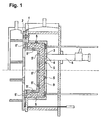
- FIG. 1 shown form has a first mold part 1 and a second mold part 2, which are in the closed state of the mold. They form between them a mold cavity 3, which is filled with a molded body 9 made of a foamed plastic.
- the first molded part 1 has in the center a filling opening 4, via which plastic particles of a thermoplastic material can be introduced into the mold cavity 3 by means of a filling injector 6.
- the first molded part 1 has two further openings 5 leading into the mold cavity 3 from the outside.
- the second mold part 2 is also provided with openings 5 'leading from outside to the mold cavity 3.
- the closed mold is first on the Golfinjektor 6 with expandable plastic particles of thermoplastic material such as EPS (polystyrene), EPP (polypropylene), EPE (polyethylene), EPS + EPE (Piocelan), TPU (thermoplastic polyurethane) or other foamable particles filled.
- EPS polystyrene
- EPP polypropylene
- EPE polyethylene
- EPS + EPE Polyethylene
- TPU thermoplastic polyurethane
- channels 10 are formed in the surface of the mold cavity 3 forming walls 11 of the first and second molded part 1, the distances 12 of ⁇ 8 mm and> 0.01 mm. These distances 12 correspond to 0.01 times to 3 times the average size of the expanded plastic particles 8, so that at least largely the air residues, which have led in the prior art to gusset volumes 7, over which to the openings 5, 5 'leading Channels 10 are discharged (See FIG. 4 ). This results in 10 pore-free surfaces of the shaped body 9, depending on the fineness of the channels.
- FIGS. 5 and 6 are shown surfaces of moldings 9, which were prepared in molds according to the invention.
- the wall of the mold cavity for the shaped body 9 was in FIG. 5 provided with parallel channels while the wall of the mold cavity for the molding in FIG. 6 had a large number of irregularly distributed surveys.
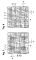
- FIG. 7 Fig. 12 shows an example of the arrangement of openings 5 "and channels 10 'in a surface of a wall 11 forming the mold cavity 3.
- the openings 5" are arranged in four circular groups.
- the small distances 12 between the channels 10' result in at least largely no air residues remaining between the expanded plastic particles 8 'and the wall 11 of the mold cavity 3.
- FIG. 8 In the example of FIG. 8 are the channels 10 'in the same way as in FIG. 7 arranged. They intersect directly or indirectly over the surface of the wall 11 of the mold cavity arranged distributed openings 5 "'
Landscapes
- Engineering & Computer Science (AREA)
- Mechanical Engineering (AREA)
- Moulds For Moulding Plastics Or The Like (AREA)
Abstract
Die Erfindung bezieht sich auf eine zwei- oder mehrteilige, einen Formhohlraum 3 aufweisende Form zur Herstellung von Formkörpern 9 aus geschäumtem Kunststoff aus in der Form expandierten Kunststoffteilchen 8, 8'. Mit einer Füllvorrichtung zum Füllen des Formhohlraums 3 über eine Füllöffnung 4 mit den Kunststoffteilchen aus thermoplastischem Kunststoff und mit einer oder mehreren Öffnungen 5, 5', 5", 5"', wobei die Oberfläche der den Formhohlraum 3 bildenden Wände 11 mit Vertiefungen versehen ist, die in die wenigstens eine nach außen führende Öffnung 5, 5', 5", 5"' münden. Die Oberfläche ist ganz oder teilweise mit einer Oberflächenstruktur versehen ist, die Kanäle 10, 10' bildet, wobei die Abstände 12 zwischen den Kanälen 10, 10' zwischen < 8 mm und > 0,01 mm sind und wobei die Kanäle 10, 10' direkt oder indirekt zur Füllöffnung und/oder zu einer oder mehreren der nach außen führenden Öffnungen 5, 5', 5", 5"' führen.

Description
Die Erfindung bezieht sich auf eine zwei- oder mehrteilige, einen Formhohlraum aufweisende Form zur Herstellung von Formkörpern aus geschäumtem Kunststoff aus in der Form expandierten Kunststoffteilchen, mit einer Füllvorrichtung zum Füllen des Formhohlraums über eine Füllöffnung mit den Kunststoffteilchen aus thermoplastischem Kunststoff und mit einer oder mehreren Öffnungen, wobei die Oberfläche der den Formhohlraum bildenden Wände mit Vertiefungen versehen ist, die in die wenigstens eine nach außen führende Öffnung münden.The invention relates to a two- or multi-part, a mold cavity having mold for the production of moldings of foamed plastic in the form of expanded plastic particles, with a filling device for filling the mold cavity via a filling opening with the plastic particles of thermoplastic material and with one or more Openings, wherein the surface of the mold cavity forming walls is provided with recesses, which open into the at least one outwardly leading opening.
Bei derartigen Formen wird der Formhohlraum über die Füllöffnung mit expandierendem Granulat aus einem Kunststoff gefüllt. Durch Bedampfungsöffnungen wird nun Dampf in den Formhohlraum eingelassen, durch den das Granulat zu einem Formkörper expandiert oder verschweißt, der den Formhohlraum vollständig ausfüllt und dessen Oberfläche offenporig ausgebildet ist. Dabei können die in dem Formhohlraum vorhandene Luft und Dampf durch die nach außen führenden Öffnungen nach außen strömen.In such forms, the mold cavity is filled via the filling opening with expanding granules of a plastic. By steaming steam is now admitted into the mold cavity through which the granules expanded or welded to form a body which completely fills the mold cavity and whose surface is open-pored. The air and steam present in the mold cavity can flow outward through the openings leading to the outside.
Bei weiteren derartigen Formen wird der Formhohlraum über die Füllöffnung mit expandierendem Granulat aus einem Kunststoff gefüllt. Durch elektrische Energie (Ultraschall, Mikrowelle, Heizstäbe oder mit Öl oder Wasser gefüllte Heizschlangen) im Werkzeug wird das Granulat erhitzt und zu einem Formkörper expandiert oder verschweißt, der den Formhohlraum vollständig ausfüllt und dessen Oberfläche offenporig ausgebildet ist. Dabei kann die in dem Formhohlraum vorhandene Luft durch die nach außen führenden Öffnungen nach außen strömen.In further such forms of the mold cavity is filled via the filling opening with expanding granules of a plastic. By electrical energy (ultrasound, microwave, heating rods or filled with oil or water heating coils) in the tool, the granules are heated and expanded or welded into a shaped body which completely fills the mold cavity and whose surface is open-pored. In this case, the air present in the mold cavity can flow through the outwardly leading openings to the outside.
Aufgabe der Erfindung ist es eine Form der eingangs genannten Art zu schaffen, die einfach aufgebaut ist und durch die die Oberfläche des Formkörpers zumindest weitgehend nichtoffenporig ausgebildet ist.The object of the invention is to provide a form of the type mentioned, which is simple and by which the surface of the molding is at least largely non-porous.
Diese Aufgabe wird erfindungsgemäß dadurch gelöst, daß die Oberfläche ganz oder teilweise mit einer Oberflächenstruktur versehen ist, die Kanäle bildet, wobei die Abstände zwischen den Kanälen zwischen < 8 mm und > 0,01 mm sind und wobei die Kanäle direkt oder indirekt zur Füllöffnung und/oder zu einer oder mehreren der nach außen führenden Öffnungen führen.This object is achieved in that the surface is wholly or partially provided with a surface structure forming channels, wherein the distances between the channels between <8 mm and> 0.01 mm and wherein the channels directly or indirectly to the filling opening and / or lead to one or more of the openings leading to the outside.
Durch diese Ausbildung können zumindest weitgehend keine Luftreste in Zwickelvolumina der Kunststoffteilchen verbleiben, die zu der Offenporigkeit der Oberfläche des Formkörpers führen würden. An der Oberfläche des Formkörpers sind abhängig von der Feinheit der Abstände der Kanäle zueinander nur noch geringe bis gar keine Poren mehr zu erkennen.As a result of this design, at least for the most part no air residues can remain in gusset volumes of the plastic particles, resulting in open porosity would lead the surface of the molding. Depending on the fineness of the distances of the channels from each other, only little or no pores can still be recognized on the surface of the shaped body.
Dies ermöglicht es Oberflächen der Formkörper von feiner Ästhetik zu schaffen.This makes it possible to create surfaces of the molded body of fine aesthetics.
Dabei entsprechen vorzugsweise die Abstände zwischen den Kanälen annähernd zwischen dem 0,01-fachen und dem 3-fachen der durchschnittlichen Größe der expandierten Kunststoffteilchen.In this case, the distances between the channels preferably correspond approximately to between 0.01 and 3 times the average size of the expanded plastic particles.
Zur guten Entlüftung und Vermeidung einer Porenbildung kann die Tiefe der Kanäle annähernd zwischen > 0,02 mm und < 3 mm und die Breite der Kanäle annähernd zwischen > 0,01 mm und < 2,5 mm sein.For good deaeration and avoidance of pore formation, the depth of the channels may be approximately between> 0.02 mm and <3 mm and the width of the channels approximately between> 0.01 mm and <2.5 mm.
Um eine gute Entlüftung zu erreichen, können über die ganze Fläche, an der eine Porenbildung vermieden werden soll, die Kanäle annähernd parallel zueinander verlaufen.In order to achieve good ventilation, the channels can be approximately parallel to each other over the entire surface at which pore formation is to be avoided.
Zu einer noch weiter verbesserten Entlüftung und Porenvermeidung führt es, wenn die Kanäle eine Gitterstruktur bilden.It leads to an even better ventilation and pore avoidance when the channels form a lattice structure.
Die Kanäle können einen regelmäßigen aber auch einen unregelmäßigen Längsverlauf aufweisen.The channels may have a regular but also an irregular longitudinal course.
Auch können die Kanäle anstatt einer regelmäßigen eine unregelmäßige Breite aufweisen.Also, the channels may have an irregular width instead of a regular one.
Sind die Kanäle die Zwischenräume zwischen einer Vielzahl regelmäßig oder unregelmäßig verteilter Erhebungen und/oder Vertiefungen an der Oberfläche der den Formhohlraum bildenden Wände, so sind sie einfach herstellbar.If the channels are the interstices between a multiplicity of regularly or irregularly distributed elevations and / or depressions on the surface of the walls forming the mold cavity, then they are easy to produce.
Dabei können die Zwischenräume eine Maserung oder eine regelmäßige oder unregelmäßige Struktur bilden.The interspaces may form a grain or a regular or irregular structure.
Diese Zwischenräume sind z.B. durch Laserbeaufschlagung oder durch Ätzen oder eine andere geeignete Materialabtragmethode kostengünstig zu erzeugen.These spaces are e.g. by laser application or by etching or other suitable Materialabtragmethode to produce cost.
Ein Ausführungsbeispiel der Erfindung ist in der Zeichnung dargestellt und wird im folgenden näher beschrieben. Es zeigen
- Figur 1
- eine Form im Querschnitt
- Figur 2
- einen Ausschnitt einer Wand eines Formhohlraums einer Form nach dem Stand der Technik mit expandierten Kunststoffteilchen
Figur 3- eine Ansicht auf einen Formkörper nach dem Stand der Technik
- Figur 4
- einen Ausschnitt einer Wand des Formhohlraums der Form nach
Figur 1 mit expandierten Kunststoffteilchen Figur 5- eine Ansicht auf einen in der Form nach
Figur 1 erzeugten Formkörper Figur 6- eine Ansicht auf einen in einer weiteren erfindungsgemäßen Form erzeugten Formkörper
Figur 7- eine Ansicht auf einen in einer erfindungsgemäßen Form erzeugten Formkörper
Figur 8- eine Ansicht auf einen in einer weiteren erfindungsgemäßen Form erzeugten Formkörper.
- FIG. 1
- a shape in cross section
- FIG. 2
- a section of a wall of a mold cavity of a mold according to the prior art with expanded plastic particles
- FIG. 3
- a view of a molded body according to the prior art
- FIG. 4
- a section of a wall of the mold cavity of the form
FIG. 1 with expanded plastic particles - FIG. 5
- a view on one in shape
FIG. 1 generated moldings - FIG. 6
- a view of a molded article produced in a further inventive form
- FIG. 7
- a view of a molded body produced in a mold according to the invention
- FIG. 8
- a view of a molded article produced in a further inventive form.
Die in
Das erste Formteil 1 weist mittig eine Füllöffnung 4 auf, über die mittels eines Füllinjektors 6 Kunststoffteilchen aus einem thermoplastischen Kunststoff in den Formhohlraum 3 einfüllbar sind.The first molded part 1 has in the center a filling opening 4, via which plastic particles of a thermoplastic material can be introduced into the
Weiterhin weist das erste Formteil 1 zwei weitere von außen in den Formhohlraum 3 führende Öffnungen 5 auf.Furthermore, the first molded part 1 has two
Das zweite Formteil 2 ist ebenfalls mit von außen zu dem Formhohlraum 3 führenden Öffnungen 5' versehen.The second mold part 2 is also provided with
Über die Öffnungen 5, 5' wird die geschlossene Form zunächst über den Füllinjektor 6 mit expandierbaren Kunststoffteilchen aus thermoplastischem Kunststoff wie EPS (Polystyrol), EPP (Polypropylen), EPE (Polyethylen), EPS+EPE (Piocelan), TPU (thermoplastisches Polyurethan) oder anderen schäumbaren Partikeln gefüllt.About the
Nach Schließen der Füllöffnung 4 wird nun über die Öffnungen 5, 5' Heißdampf in den Formhohlraum 3 eingeführt, wodurch die Kunststoffteilchen expandieren, bis der Formhohlraum 3 den Formkörper 9 bildend vollständig ausgefüllt ist. Dabei dienen die Öffnungen 5, 5' zum Ausströmen der in dem Formhohlraum 3 enthaltenen Luft, Dampf und kondensiertem Wasser.After closing the filling opening 4 hot steam is now introduced into the
Bei einer Form nach dem Stand der Technik bilden sich zwischen der Oberfläche der den Formhohlraum 3 bildenden Wände 11 des ersten und zweiten Formteils 1, 2 und den expandierten Kunststoffteilchen 8' Zwickelvolumina 7 von Luftresten, wie in
Bei der erfindungsgemäßen Form sind in der Oberfläche der den Formhohlraum 3 bildenden Wände 11 des ersten und zweiten Formteils 1, 2 Kanäle 10 ausgebildet, die Abstände 12 von <8 mm und >0,01 mm aufweisen. Diese Abstände 12 entsprechen dem 0,01-fachen bis 3-fachen der durchschnittlichen Größe der expandierten Kunststoffteilchen 8, so daß zumindest weitgehend die Luftreste, die beim Stand der Technik zu Zwickelvolumina 7 geführt haben, über die zu den Öffnungen 5, 5' führenden Kanäle 10 abgeführt werden (Siehe
In den
In
Bei dem Beispiel der
- 11
- erstes Formteilfirst molding
- 22
- zweites Formteilsecond molding
- 33
- Formhohlraummold cavity
- 44
- Füllöffnungfill opening
- 55
- Öffnungenopenings
- 5'5 '
- Öffnungenopenings
- 5"5 '
- Öffnungenopenings
- 66
- Füllinjektorfilling injector
- 77
- ZwickelvoluminaZwickel volumes
- 88th
- expandierte Kunststoffteilchenexpanded plastic particles
- 8'8th'
- expandierte Kunststoffteilchenexpanded plastic particles
- 99
- Formkörpermoldings
- 1010
- Kanälechannels
- 10'10 '
- Kanälechannels
- 1111
- Wandwall
- 1212
- Abständedistances
Claims (11)
Priority Applications (1)
| Application Number | Priority Date | Filing Date | Title |
|---|---|---|---|
| PL14185371T PL2857166T3 (en) | 2013-10-07 | 2014-09-18 | Mould |
Applications Claiming Priority (1)
| Application Number | Priority Date | Filing Date | Title |
|---|---|---|---|
| DE102013111078.9A DE102013111078A1 (en) | 2013-10-07 | 2013-10-07 | shape |
Related Child Applications (1)
| Application Number | Title | Priority Date | Filing Date |
|---|---|---|---|
| EP18203761.4 Division-Into | 2018-10-31 |
Publications (2)
| Publication Number | Publication Date |
|---|---|
| EP2857166A1 true EP2857166A1 (en) | 2015-04-08 |
| EP2857166B1 EP2857166B1 (en) | 2020-05-27 |
Family
ID=51582272
Family Applications (1)
| Application Number | Title | Priority Date | Filing Date |
|---|---|---|---|
| EP14185371.3A Active EP2857166B1 (en) | 2013-10-07 | 2014-09-18 | Mould |
Country Status (6)
| Country | Link |
|---|---|
| EP (1) | EP2857166B1 (en) |
| CN (1) | CN104511998B (en) |
| DE (1) | DE102013111078A1 (en) |
| HU (1) | HUE051033T2 (en) |
| PL (1) | PL2857166T3 (en) |
| PT (1) | PT2857166T (en) |
Cited By (1)
| Publication number | Priority date | Publication date | Assignee | Title |
|---|---|---|---|---|
| DE102017201123A1 (en) | 2017-01-24 | 2018-07-26 | Volkswagen Aktiengesellschaft | Interior trim component |
Families Citing this family (1)
| Publication number | Priority date | Publication date | Assignee | Title |
|---|---|---|---|---|
| CN108908836A (en) * | 2018-06-30 | 2018-11-30 | 青岛天运恒远泡塑机械设备有限公司 | The production technology of block-resistant type mold and the mold |
Citations (5)
| Publication number | Priority date | Publication date | Assignee | Title |
|---|---|---|---|---|
| GB732287A (en) * | 1952-04-12 | 1955-06-22 | Giuseppe Olmo Spa | Improved manufacture of articles made of spongy or cellular rubber |
| JPH0585609U (en) * | 1992-04-24 | 1993-11-19 | 西川化成株式会社 | Foam mold |
| JPH06320634A (en) * | 1993-05-13 | 1994-11-22 | Kanegafuchi Chem Ind Co Ltd | Mold for thermoplastic resin in-mold foam molding and thermoplastic resin in-mold foam molded article |
| JPH07108346A (en) * | 1993-10-08 | 1995-04-25 | Toyota Motor Corp | Mold for foam model |
| DE112011102871T5 (en) * | 2010-08-31 | 2013-06-06 | Sekisui Plastics Co., Ltd. | Shaped foam |
Family Cites Families (3)
| Publication number | Priority date | Publication date | Assignee | Title |
|---|---|---|---|---|
| JP2004230590A (en) * | 2003-01-28 | 2004-08-19 | Sekisui Plastics Co Ltd | Foam resin molds and molded products |
| DE202007005687U1 (en) * | 2007-04-18 | 2007-09-06 | Philippine Gmbh & Co. Technische Kunststoffe Kg | molding |
| CH700111B1 (en) | 2009-09-25 | 2010-06-30 | Agie Sa | Machine for making three-dimensional workpiece using focused beam of laser light causing local evaporation of particle of matter on workpiece surface, comprises laser machining head, laser source, galvanometer scanner, and optical fiber |
-
2013
- 2013-10-07 DE DE102013111078.9A patent/DE102013111078A1/en active Pending
-
2014
- 2014-09-18 HU HUE14185371A patent/HUE051033T2/en unknown
- 2014-09-18 EP EP14185371.3A patent/EP2857166B1/en active Active
- 2014-09-18 PL PL14185371T patent/PL2857166T3/en unknown
- 2014-09-18 PT PT141853713T patent/PT2857166T/en unknown
- 2014-10-08 CN CN201410525834.4A patent/CN104511998B/en active Active
Patent Citations (5)
| Publication number | Priority date | Publication date | Assignee | Title |
|---|---|---|---|---|
| GB732287A (en) * | 1952-04-12 | 1955-06-22 | Giuseppe Olmo Spa | Improved manufacture of articles made of spongy or cellular rubber |
| JPH0585609U (en) * | 1992-04-24 | 1993-11-19 | 西川化成株式会社 | Foam mold |
| JPH06320634A (en) * | 1993-05-13 | 1994-11-22 | Kanegafuchi Chem Ind Co Ltd | Mold for thermoplastic resin in-mold foam molding and thermoplastic resin in-mold foam molded article |
| JPH07108346A (en) * | 1993-10-08 | 1995-04-25 | Toyota Motor Corp | Mold for foam model |
| DE112011102871T5 (en) * | 2010-08-31 | 2013-06-06 | Sekisui Plastics Co., Ltd. | Shaped foam |
Cited By (1)
| Publication number | Priority date | Publication date | Assignee | Title |
|---|---|---|---|---|
| DE102017201123A1 (en) | 2017-01-24 | 2018-07-26 | Volkswagen Aktiengesellschaft | Interior trim component |
Also Published As
| Publication number | Publication date |
|---|---|
| CN104511998B (en) | 2017-04-12 |
| DE102013111078A1 (en) | 2015-04-09 |
| CN104511998A (en) | 2015-04-15 |
| PT2857166T (en) | 2020-08-20 |
| PL2857166T3 (en) | 2020-11-02 |
| HUE051033T2 (en) | 2021-01-28 |
| EP2857166B1 (en) | 2020-05-27 |
Similar Documents
| Publication | Publication Date | Title |
|---|---|---|
| WO2003043795A1 (en) | Form tool for producing particle foam moulded parts | |
| DE102013003167A1 (en) | Method for producing a three-dimensional object by generative construction | |
| DE102019215845A1 (en) | Tool, tool system and method for the production of foamed particle parts, in particular for the production of shoe soles | |
| DE602004002318T2 (en) | Forming device for mold foaming and casting | |
| DE10321507A1 (en) | Cast plastic objects and method of making the same | |
| EP2857166B1 (en) | Mould | |
| DE102014104680A1 (en) | Method and device for molding a component | |
| DE102013226906A1 (en) | Multi-part blow mold for the production of blown, plastic workpieces, as well as processes for their production | |
| EP2770096B1 (en) | Warp knitting element carrying bar of synthetic material | |
| EP3661718B1 (en) | Tool | |
| EP2601026B1 (en) | Process and device for producing plastic parisons for large-volume containers | |
| DE102009016110A1 (en) | Method for the production of a mold insert for a casting mold for injection molding, comprises applying a powder forming material in a thin layer on a base surface and melting a defined area of the layer with a high energetic beam | |
| DE102016222437A1 (en) | Method of manufacturing an instrument panel, instrument panel and motor vehicle | |
| EP2724832B1 (en) | Method for producing a brick with insulating filler | |
| DE102010018114B4 (en) | Process for the production of components by means of polymer or plastic casting or fiber composite plastics | |
| EP3291961A1 (en) | Method and device for producing large-volume containers with a flange by plastic blow molding | |
| DE102013018578A1 (en) | Process for producing a polyurethane-flooded plastic component | |
| EP3687757B1 (en) | Tool for processing foamable and/or pre-foamed plastic particles | |
| DE102014217756B4 (en) | Process for manufacturing a fiber-reinforced plastic part and fiber-reinforced plastic part | |
| EP3023235B1 (en) | Method for producing fibre composite components and a fiber composite component | |
| WO2016173970A1 (en) | Molding tool | |
| EP0679488B1 (en) | Process and mould for making foam articles of at least two different densities | |
| DE102012019803A1 (en) | Method for manufacturing particle foam-mold part e.g. sun visor of motor car, involves forming regions of mold part with certain thickness, cooling, curing and maintaining mold part, opening foam shaping tool, and ejecting mold part | |
| DE102020115696B4 (en) | Process for producing a molded part | |
| WO2009021346A2 (en) | Process and device for producing prefabricated parts |
Legal Events
| Date | Code | Title | Description |
|---|---|---|---|
| PUAI | Public reference made under article 153(3) epc to a published international application that has entered the european phase |
Free format text: ORIGINAL CODE: 0009012 |
|
| 17P | Request for examination filed |
Effective date: 20140918 |
|
| AK | Designated contracting states |
Kind code of ref document: A1 Designated state(s): AL AT BE BG CH CY CZ DE DK EE ES FI FR GB GR HR HU IE IS IT LI LT LU LV MC MK MT NL NO PL PT RO RS SE SI SK SM TR |
|
| AX | Request for extension of the european patent |
Extension state: BA ME |
|
| RAP3 | Party data changed (applicant data changed or rights of an application transferred) |
Owner name: THORSTEN, MICHEL |
|
| RIN1 | Information on inventor provided before grant (corrected) |
Inventor name: THORSTEN, MICHEL |
|
| R17P | Request for examination filed (corrected) |
Effective date: 20150529 |
|
| RBV | Designated contracting states (corrected) |
Designated state(s): AL AT BE BG CH CY CZ DE DK EE ES FI FR GB GR HR HU IE IS IT LI LT LU LV MC MK MT NL NO PL PT RO RS SE SI SK SM TR |
|
| 17Q | First examination report despatched |
Effective date: 20150924 |
|
| APBK | Appeal reference recorded |
Free format text: ORIGINAL CODE: EPIDOSNREFNE |
|
| APBN | Date of receipt of notice of appeal recorded |
Free format text: ORIGINAL CODE: EPIDOSNNOA2E |
|
| APBR | Date of receipt of statement of grounds of appeal recorded |
Free format text: ORIGINAL CODE: EPIDOSNNOA3E |
|
| APAF | Appeal reference modified |
Free format text: ORIGINAL CODE: EPIDOSCREFNE |
|
| APBT | Appeal procedure closed |
Free format text: ORIGINAL CODE: EPIDOSNNOA9E |
|
| GRAP | Despatch of communication of intention to grant a patent |
Free format text: ORIGINAL CODE: EPIDOSNIGR1 |
|
| STAA | Information on the status of an ep patent application or granted ep patent |
Free format text: STATUS: GRANT OF PATENT IS INTENDED |
|
| INTG | Intention to grant announced |
Effective date: 20190426 |
|
| GRAJ | Information related to disapproval of communication of intention to grant by the applicant or resumption of examination proceedings by the epo deleted |
Free format text: ORIGINAL CODE: EPIDOSDIGR1 |
|
| STAA | Information on the status of an ep patent application or granted ep patent |
Free format text: STATUS: EXAMINATION IS IN PROGRESS |
|
| INTC | Intention to grant announced (deleted) | ||
| GRAS | Grant fee paid |
Free format text: ORIGINAL CODE: EPIDOSNIGR3 |
|
| STAA | Information on the status of an ep patent application or granted ep patent |
Free format text: STATUS: GRANT OF PATENT IS INTENDED |
|
| GRAP | Despatch of communication of intention to grant a patent |
Free format text: ORIGINAL CODE: EPIDOSNIGR1 |
|
| INTG | Intention to grant announced |
Effective date: 20191219 |
|
| GRAA | (expected) grant |
Free format text: ORIGINAL CODE: 0009210 |
|
| STAA | Information on the status of an ep patent application or granted ep patent |
Free format text: STATUS: THE PATENT HAS BEEN GRANTED |
|
| AK | Designated contracting states |
Kind code of ref document: B1 Designated state(s): AL AT BE BG CH CY CZ DE DK EE ES FI FR GB GR HR HU IE IS IT LI LT LU LV MC MK MT NL NO PL PT RO RS SE SI SK SM TR |
|
| REG | Reference to a national code |
Ref country code: GB Ref legal event code: FG4D Free format text: NOT ENGLISH |
|
| REG | Reference to a national code |
Ref country code: CH Ref legal event code: EP |
|
| REG | Reference to a national code |
Ref country code: AT Ref legal event code: REF Ref document number: 1274110 Country of ref document: AT Kind code of ref document: T Effective date: 20200615 |
|
| REG | Reference to a national code |
Ref country code: DE Ref legal event code: R096 Ref document number: 502014014219 Country of ref document: DE |
|
| REG | Reference to a national code |
Ref country code: CH Ref legal event code: NV Representative=s name: ISLER AND PEDRAZZINI AG, CH |
|
| REG | Reference to a national code |
Ref country code: PT Ref legal event code: SC4A Ref document number: 2857166 Country of ref document: PT Date of ref document: 20200820 Kind code of ref document: T Free format text: AVAILABILITY OF NATIONAL TRANSLATION Effective date: 20200806 |
|
| REG | Reference to a national code |
Ref country code: SE Ref legal event code: TRGR |
|
| REG | Reference to a national code |
Ref country code: LT Ref legal event code: MG4D |
|
| PG25 | Lapsed in a contracting state [announced via postgrant information from national office to epo] |
Ref country code: NO Free format text: LAPSE BECAUSE OF FAILURE TO SUBMIT A TRANSLATION OF THE DESCRIPTION OR TO PAY THE FEE WITHIN THE PRESCRIBED TIME-LIMIT Effective date: 20200827 Ref country code: LT Free format text: LAPSE BECAUSE OF FAILURE TO SUBMIT A TRANSLATION OF THE DESCRIPTION OR TO PAY THE FEE WITHIN THE PRESCRIBED TIME-LIMIT Effective date: 20200527 Ref country code: FI Free format text: LAPSE BECAUSE OF FAILURE TO SUBMIT A TRANSLATION OF THE DESCRIPTION OR TO PAY THE FEE WITHIN THE PRESCRIBED TIME-LIMIT Effective date: 20200527 Ref country code: IS Free format text: LAPSE BECAUSE OF FAILURE TO SUBMIT A TRANSLATION OF THE DESCRIPTION OR TO PAY THE FEE WITHIN THE PRESCRIBED TIME-LIMIT Effective date: 20200927 Ref country code: GR Free format text: LAPSE BECAUSE OF FAILURE TO SUBMIT A TRANSLATION OF THE DESCRIPTION OR TO PAY THE FEE WITHIN THE PRESCRIBED TIME-LIMIT Effective date: 20200828 |
|
| REG | Reference to a national code |
Ref country code: NL Ref legal event code: MP Effective date: 20200527 |
|
| PG25 | Lapsed in a contracting state [announced via postgrant information from national office to epo] |
Ref country code: RS Free format text: LAPSE BECAUSE OF FAILURE TO SUBMIT A TRANSLATION OF THE DESCRIPTION OR TO PAY THE FEE WITHIN THE PRESCRIBED TIME-LIMIT Effective date: 20200527 Ref country code: BG Free format text: LAPSE BECAUSE OF FAILURE TO SUBMIT A TRANSLATION OF THE DESCRIPTION OR TO PAY THE FEE WITHIN THE PRESCRIBED TIME-LIMIT Effective date: 20200827 Ref country code: LV Free format text: LAPSE BECAUSE OF FAILURE TO SUBMIT A TRANSLATION OF THE DESCRIPTION OR TO PAY THE FEE WITHIN THE PRESCRIBED TIME-LIMIT Effective date: 20200527 Ref country code: HR Free format text: LAPSE BECAUSE OF FAILURE TO SUBMIT A TRANSLATION OF THE DESCRIPTION OR TO PAY THE FEE WITHIN THE PRESCRIBED TIME-LIMIT Effective date: 20200527 |
|
| REG | Reference to a national code |
Ref country code: SK Ref legal event code: T3 Ref document number: E 35448 Country of ref document: SK |
|
| PG25 | Lapsed in a contracting state [announced via postgrant information from national office to epo] |
Ref country code: AL Free format text: LAPSE BECAUSE OF FAILURE TO SUBMIT A TRANSLATION OF THE DESCRIPTION OR TO PAY THE FEE WITHIN THE PRESCRIBED TIME-LIMIT Effective date: 20200527 Ref country code: NL Free format text: LAPSE BECAUSE OF FAILURE TO SUBMIT A TRANSLATION OF THE DESCRIPTION OR TO PAY THE FEE WITHIN THE PRESCRIBED TIME-LIMIT Effective date: 20200527 |
|
| REG | Reference to a national code |
Ref country code: HU Ref legal event code: AG4A Ref document number: E051033 Country of ref document: HU |
|
| PG25 | Lapsed in a contracting state [announced via postgrant information from national office to epo] |
Ref country code: ES Free format text: LAPSE BECAUSE OF FAILURE TO SUBMIT A TRANSLATION OF THE DESCRIPTION OR TO PAY THE FEE WITHIN THE PRESCRIBED TIME-LIMIT Effective date: 20200527 Ref country code: DK Free format text: LAPSE BECAUSE OF FAILURE TO SUBMIT A TRANSLATION OF THE DESCRIPTION OR TO PAY THE FEE WITHIN THE PRESCRIBED TIME-LIMIT Effective date: 20200527 Ref country code: EE Free format text: LAPSE BECAUSE OF FAILURE TO SUBMIT A TRANSLATION OF THE DESCRIPTION OR TO PAY THE FEE WITHIN THE PRESCRIBED TIME-LIMIT Effective date: 20200527 Ref country code: RO Free format text: LAPSE BECAUSE OF FAILURE TO SUBMIT A TRANSLATION OF THE DESCRIPTION OR TO PAY THE FEE WITHIN THE PRESCRIBED TIME-LIMIT Effective date: 20200527 Ref country code: SM Free format text: LAPSE BECAUSE OF FAILURE TO SUBMIT A TRANSLATION OF THE DESCRIPTION OR TO PAY THE FEE WITHIN THE PRESCRIBED TIME-LIMIT Effective date: 20200527 |
|
| REG | Reference to a national code |
Ref country code: DE Ref legal event code: R026 Ref document number: 502014014219 Country of ref document: DE |
|
| PLBI | Opposition filed |
Free format text: ORIGINAL CODE: 0009260 |
|
| PLAX | Notice of opposition and request to file observation + time limit sent |
Free format text: ORIGINAL CODE: EPIDOSNOBS2 |
|
| 26 | Opposition filed |
Opponent name: HIRSCH MASCHINENBAU GMBH Effective date: 20210301 Opponent name: SCHRAML METALLVERARBEITUNG GMBH & CO. KG Effective date: 20210301 |
|
| PG25 | Lapsed in a contracting state [announced via postgrant information from national office to epo] |
Ref country code: MC Free format text: LAPSE BECAUSE OF FAILURE TO SUBMIT A TRANSLATION OF THE DESCRIPTION OR TO PAY THE FEE WITHIN THE PRESCRIBED TIME-LIMIT Effective date: 20200527 |
|
| PG25 | Lapsed in a contracting state [announced via postgrant information from national office to epo] |
Ref country code: SI Free format text: LAPSE BECAUSE OF FAILURE TO SUBMIT A TRANSLATION OF THE DESCRIPTION OR TO PAY THE FEE WITHIN THE PRESCRIBED TIME-LIMIT Effective date: 20200527 |
|
| PG25 | Lapsed in a contracting state [announced via postgrant information from national office to epo] |
Ref country code: LU Free format text: LAPSE BECAUSE OF NON-PAYMENT OF DUE FEES Effective date: 20200918 |
|
| PLBB | Reply of patent proprietor to notice(s) of opposition received |
Free format text: ORIGINAL CODE: EPIDOSNOBS3 |
|
| PG25 | Lapsed in a contracting state [announced via postgrant information from national office to epo] |
Ref country code: IE Free format text: LAPSE BECAUSE OF NON-PAYMENT OF DUE FEES Effective date: 20200918 |
|
| PGFP | Annual fee paid to national office [announced via postgrant information from national office to epo] |
Ref country code: BE Payment date: 20210921 Year of fee payment: 8 |
|
| PG25 | Lapsed in a contracting state [announced via postgrant information from national office to epo] |
Ref country code: MT Free format text: LAPSE BECAUSE OF FAILURE TO SUBMIT A TRANSLATION OF THE DESCRIPTION OR TO PAY THE FEE WITHIN THE PRESCRIBED TIME-LIMIT Effective date: 20200527 Ref country code: CY Free format text: LAPSE BECAUSE OF FAILURE TO SUBMIT A TRANSLATION OF THE DESCRIPTION OR TO PAY THE FEE WITHIN THE PRESCRIBED TIME-LIMIT Effective date: 20200527 |
|
| PG25 | Lapsed in a contracting state [announced via postgrant information from national office to epo] |
Ref country code: MK Free format text: LAPSE BECAUSE OF FAILURE TO SUBMIT A TRANSLATION OF THE DESCRIPTION OR TO PAY THE FEE WITHIN THE PRESCRIBED TIME-LIMIT Effective date: 20200527 |
|
| REG | Reference to a national code |
Ref country code: BE Ref legal event code: MM Effective date: 20220930 |
|
| P01 | Opt-out of the competence of the unified patent court (upc) registered |
Effective date: 20230502 |
|
| PG25 | Lapsed in a contracting state [announced via postgrant information from national office to epo] |
Ref country code: BE Free format text: LAPSE BECAUSE OF NON-PAYMENT OF DUE FEES Effective date: 20220930 |
|
| PGFP | Annual fee paid to national office [announced via postgrant information from national office to epo] |
Ref country code: TR Payment date: 20230908 Year of fee payment: 10 |
|
| PGFP | Annual fee paid to national office [announced via postgrant information from national office to epo] |
Ref country code: PT Payment date: 20230912 Year of fee payment: 10 |
|
| PG25 | Lapsed in a contracting state [announced via postgrant information from national office to epo] |
Ref country code: PT Free format text: LAPSE BECAUSE OF NON-PAYMENT OF DUE FEES Effective date: 20250318 |
|
| REG | Reference to a national code |
Ref country code: CH Ref legal event code: U11 Free format text: ST27 STATUS EVENT CODE: U-0-0-U10-U11 (AS PROVIDED BY THE NATIONAL OFFICE) Effective date: 20251001 |
|
| PGFP | Annual fee paid to national office [announced via postgrant information from national office to epo] |
Ref country code: DE Payment date: 20250827 Year of fee payment: 12 |
|
| PGFP | Annual fee paid to national office [announced via postgrant information from national office to epo] |
Ref country code: PL Payment date: 20250908 Year of fee payment: 12 |
|
| PGFP | Annual fee paid to national office [announced via postgrant information from national office to epo] |
Ref country code: HU Payment date: 20250911 Year of fee payment: 12 Ref country code: GB Payment date: 20250923 Year of fee payment: 12 |
|
| PGFP | Annual fee paid to national office [announced via postgrant information from national office to epo] |
Ref country code: FR Payment date: 20250922 Year of fee payment: 12 Ref country code: AT Payment date: 20250918 Year of fee payment: 12 |
|
| PGFP | Annual fee paid to national office [announced via postgrant information from national office to epo] |
Ref country code: SE Payment date: 20250922 Year of fee payment: 12 |
|
| PGFP | Annual fee paid to national office [announced via postgrant information from national office to epo] |
Ref country code: CZ Payment date: 20250905 Year of fee payment: 12 |
|
| PGFP | Annual fee paid to national office [announced via postgrant information from national office to epo] |
Ref country code: SK Payment date: 20250910 Year of fee payment: 12 |
|
| PGFP | Annual fee paid to national office [announced via postgrant information from national office to epo] |
Ref country code: IT Payment date: 20250930 Year of fee payment: 12 |
|
| PGFP | Annual fee paid to national office [announced via postgrant information from national office to epo] |
Ref country code: CH Payment date: 20251001 Year of fee payment: 12 |