EP2857134A1 - Brazing method - Google Patents
Brazing method Download PDFInfo
- Publication number
- EP2857134A1 EP2857134A1 EP14185440.6A EP14185440A EP2857134A1 EP 2857134 A1 EP2857134 A1 EP 2857134A1 EP 14185440 A EP14185440 A EP 14185440A EP 2857134 A1 EP2857134 A1 EP 2857134A1
- Authority
- EP
- European Patent Office
- Prior art keywords
- substrate
- braze
- groove
- assembly
- brazing method
- Prior art date
- Legal status (The legal status is an assumption and is not a legal conclusion. Google has not performed a legal analysis and makes no representation as to the accuracy of the status listed.)
- Granted
Links
- 238000005219 brazing Methods 0.000 title claims abstract description 64
- 238000000034 method Methods 0.000 title claims abstract description 46
- 239000000758 substrate Substances 0.000 claims abstract description 76
- 239000000463 material Substances 0.000 claims abstract description 70
- 238000010438 heat treatment Methods 0.000 claims abstract description 17
- 238000003825 pressing Methods 0.000 claims abstract description 3
- 238000001816 cooling Methods 0.000 claims description 29
- 229910045601 alloy Inorganic materials 0.000 claims description 16
- 239000000956 alloy Substances 0.000 claims description 16
- PXHVJJICTQNCMI-UHFFFAOYSA-N Nickel Chemical compound [Ni] PXHVJJICTQNCMI-UHFFFAOYSA-N 0.000 claims description 14
- 238000002844 melting Methods 0.000 claims description 13
- 229910000743 fusible alloy Inorganic materials 0.000 claims description 7
- 229910052759 nickel Inorganic materials 0.000 claims description 7
- 239000011230 binding agent Substances 0.000 claims description 4
- 239000000919 ceramic Substances 0.000 claims description 4
- 229910000531 Co alloy Inorganic materials 0.000 claims description 2
- 238000007665 sagging Methods 0.000 description 8
- 230000008018 melting Effects 0.000 description 6
- 239000000203 mixture Substances 0.000 description 6
- 230000015572 biosynthetic process Effects 0.000 description 5
- 238000000576 coating method Methods 0.000 description 5
- 239000011248 coating agent Substances 0.000 description 4
- 239000012530 fluid Substances 0.000 description 4
- 229910052799 carbon Inorganic materials 0.000 description 3
- 229910052804 chromium Inorganic materials 0.000 description 3
- 239000011651 chromium Substances 0.000 description 3
- 229910001092 metal group alloy Inorganic materials 0.000 description 3
- OKTJSMMVPCPJKN-UHFFFAOYSA-N Carbon Chemical compound [C] OKTJSMMVPCPJKN-UHFFFAOYSA-N 0.000 description 2
- VYZAMTAEIAYCRO-UHFFFAOYSA-N Chromium Chemical compound [Cr] VYZAMTAEIAYCRO-UHFFFAOYSA-N 0.000 description 2
- 229910052782 aluminium Inorganic materials 0.000 description 2
- 229910052796 boron Inorganic materials 0.000 description 2
- 229910052735 hafnium Inorganic materials 0.000 description 2
- 229910052751 metal Inorganic materials 0.000 description 2
- 239000002184 metal Substances 0.000 description 2
- 229910052750 molybdenum Inorganic materials 0.000 description 2
- 239000000843 powder Substances 0.000 description 2
- 229910052710 silicon Inorganic materials 0.000 description 2
- 229910052715 tantalum Inorganic materials 0.000 description 2
- 229910052721 tungsten Inorganic materials 0.000 description 2
- 229910000851 Alloy steel Inorganic materials 0.000 description 1
- ZOXJGFHDIHLPTG-UHFFFAOYSA-N Boron Chemical compound [B] ZOXJGFHDIHLPTG-UHFFFAOYSA-N 0.000 description 1
- ZOKXTWBITQBERF-UHFFFAOYSA-N Molybdenum Chemical compound [Mo] ZOKXTWBITQBERF-UHFFFAOYSA-N 0.000 description 1
- 229910000831 Steel Inorganic materials 0.000 description 1
- XAGFODPZIPBFFR-UHFFFAOYSA-N aluminium Chemical compound [Al] XAGFODPZIPBFFR-UHFFFAOYSA-N 0.000 description 1
- 230000000903 blocking effect Effects 0.000 description 1
- 229910017052 cobalt Inorganic materials 0.000 description 1
- 239000010941 cobalt Substances 0.000 description 1
- GUTLYIVDDKVIGB-UHFFFAOYSA-N cobalt atom Chemical compound [Co] GUTLYIVDDKVIGB-UHFFFAOYSA-N 0.000 description 1
- 239000012809 cooling fluid Substances 0.000 description 1
- 229910052802 copper Inorganic materials 0.000 description 1
- VBJZVLUMGGDVMO-UHFFFAOYSA-N hafnium atom Chemical compound [Hf] VBJZVLUMGGDVMO-UHFFFAOYSA-N 0.000 description 1
- 229910052742 iron Inorganic materials 0.000 description 1
- 229910052748 manganese Inorganic materials 0.000 description 1
- 150000002739 metals Chemical class 0.000 description 1
- 238000012986 modification Methods 0.000 description 1
- 230000004048 modification Effects 0.000 description 1
- 239000011733 molybdenum Substances 0.000 description 1
- 229910052758 niobium Inorganic materials 0.000 description 1
- 230000001590 oxidative effect Effects 0.000 description 1
- 229910052702 rhenium Inorganic materials 0.000 description 1
- WUAPFZMCVAUBPE-UHFFFAOYSA-N rhenium atom Chemical compound [Re] WUAPFZMCVAUBPE-UHFFFAOYSA-N 0.000 description 1
- 239000010703 silicon Substances 0.000 description 1
- 238000005245 sintering Methods 0.000 description 1
- 239000007787 solid Substances 0.000 description 1
- 239000010959 steel Substances 0.000 description 1
- GUVRBAGPIYLISA-UHFFFAOYSA-N tantalum atom Chemical compound [Ta] GUVRBAGPIYLISA-UHFFFAOYSA-N 0.000 description 1
- 238000007751 thermal spraying Methods 0.000 description 1
- WFKWXMTUELFFGS-UHFFFAOYSA-N tungsten Chemical compound [W] WFKWXMTUELFFGS-UHFFFAOYSA-N 0.000 description 1
- 239000010937 tungsten Substances 0.000 description 1
- 229910052726 zirconium Inorganic materials 0.000 description 1
Images


Classifications
-
- B—PERFORMING OPERATIONS; TRANSPORTING
- B23—MACHINE TOOLS; METAL-WORKING NOT OTHERWISE PROVIDED FOR
- B23K—SOLDERING OR UNSOLDERING; WELDING; CLADDING OR PLATING BY SOLDERING OR WELDING; CUTTING BY APPLYING HEAT LOCALLY, e.g. FLAME CUTTING; WORKING BY LASER BEAM
- B23K1/00—Soldering, e.g. brazing, or unsoldering
- B23K1/0008—Soldering, e.g. brazing, or unsoldering specially adapted for particular articles or work
- B23K1/0018—Brazing of turbine parts
-
- B—PERFORMING OPERATIONS; TRANSPORTING
- B23—MACHINE TOOLS; METAL-WORKING NOT OTHERWISE PROVIDED FOR
- B23K—SOLDERING OR UNSOLDERING; WELDING; CLADDING OR PLATING BY SOLDERING OR WELDING; CUTTING BY APPLYING HEAT LOCALLY, e.g. FLAME CUTTING; WORKING BY LASER BEAM
- B23K1/00—Soldering, e.g. brazing, or unsoldering
- B23K1/19—Soldering, e.g. brazing, or unsoldering taking account of the properties of the materials to be soldered
-
- B—PERFORMING OPERATIONS; TRANSPORTING
- B23—MACHINE TOOLS; METAL-WORKING NOT OTHERWISE PROVIDED FOR
- B23K—SOLDERING OR UNSOLDERING; WELDING; CLADDING OR PLATING BY SOLDERING OR WELDING; CUTTING BY APPLYING HEAT LOCALLY, e.g. FLAME CUTTING; WORKING BY LASER BEAM
- B23K1/00—Soldering, e.g. brazing, or unsoldering
- B23K1/20—Preliminary treatment of work or areas to be soldered, e.g. in respect of a galvanic coating
-
- B—PERFORMING OPERATIONS; TRANSPORTING
- B23—MACHINE TOOLS; METAL-WORKING NOT OTHERWISE PROVIDED FOR
- B23K—SOLDERING OR UNSOLDERING; WELDING; CLADDING OR PLATING BY SOLDERING OR WELDING; CUTTING BY APPLYING HEAT LOCALLY, e.g. FLAME CUTTING; WORKING BY LASER BEAM
- B23K31/00—Processes relevant to this subclass, specially adapted for particular articles or purposes, but not covered by only one of the preceding main groups
- B23K31/02—Processes relevant to this subclass, specially adapted for particular articles or purposes, but not covered by only one of the preceding main groups relating to soldering or welding
-
- B—PERFORMING OPERATIONS; TRANSPORTING
- B23—MACHINE TOOLS; METAL-WORKING NOT OTHERWISE PROVIDED FOR
- B23K—SOLDERING OR UNSOLDERING; WELDING; CLADDING OR PLATING BY SOLDERING OR WELDING; CUTTING BY APPLYING HEAT LOCALLY, e.g. FLAME CUTTING; WORKING BY LASER BEAM
- B23K2101/00—Articles made by soldering, welding or cutting
- B23K2101/001—Turbines
Definitions
- the present invention is directed to a brazing method. More specifically, the present invention is directed to brazing methods for forming cooling microchannels.
- Turbine systems are continuously being modified to increase efficiency and decrease cost.
- One method for increasing the efficiency of a turbine system includes increasing the operating temperature of the turbine system. To increase the temperature, the turbine system must be constructed of materials which can withstand such temperatures during continued use.
- the temperature capability of a turbine component may be increased through the use of cooling microchannels.
- the cooling microchannels can be incorporated into metals and alloys used in high temperature regions of gas turbines.
- forming an exterior cover over the cooling microchannels can be difficult as thermal spraying directly over the channel can result in coating material filling the channel.
- One method to prevent the coating material from filling the channel includes filling the channel with a sacrificial material prior to coating, then coating the component and subsequently leeching out the sacrificial material. The filling and removing of the sacrificial material can be both difficult and expensive.
- a thin cover layer can be brazed to the substrate, over the cooling microchannel.
- the brazing temperatures required to sufficiently braze the material may also soften the braze cover material.
- the softened material can sag or droop into the cooling microchannels, blocking them as they harden. As such, brazing requires a very narrow temperature range, outside of which the component can be damaged or made unusable.
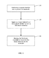
- a brazing method includes providing a substrate having at least one groove. Next, a support member is provided and positioned over the at least one groove in the substrate. A braze material is provided and applied over the support member, the support member and the braze material forming a first braze assembly. Next, the first braze assembly is heated to braze the first braze assembly to the substrate.
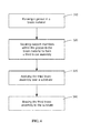
- a brazing method includes providing a preform, providing a mesh, pressing the mesh into the preform, heating the preform to form a second braze assembly, providing a substrate, providing at least one groove in the substrate, applying the second braze assembly over the at least one groove in the substrate, then brazing the second braze assembly to the substrate.
- a brazing method includes providing a braze material, forming at least one groove in the braze material, securing support members within the at least one groove to form a third braze assembly, providing a substrate, applying the third braze assembly over the substrate, and brazing the third braze assembly to the substrate to form a brazed article.
- the at least one groove in the third braze assembly forms at least one cooling microchannel in the brazed article.
- Embodiments of the present disclosure in comparison to processes and articles not using one or more of the features disclosed herein, increase efficiency of cooling microchannel formation, decrease cost of cooling microchannel formation, decrease encroachment of braze material into cooling microchannels during brazing, permit increased brazing temperatures, decrease scrap rate during brazing, permit formation of cooling microchannels in the braze material, or a combination thereof.
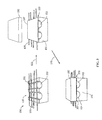
- a brazing method 100 includes providing a substrate 101 having at least one groove 103, providing a support member 105, positioning the support member 105 over the groove 103 in the substrate 101 (step 110), providing a braze material 107, applying the braze material 107 over the support member 105 (step 120) to form a first braze assembly 109 comprising the support member 105 and the braze material 107, and heating the first braze assembly 109 (step 130) to braze the first braze assembly 109 to the substrate 101.
- the braze material 107 may be formed with a thickness of up to 30 mils, up to 25 mils, up to 20 mils, or a combination thereof.
- the brazing is performed by any suitable braze method capable of securing the braze material 107 of the first braze assembly 109 to the substrate 101 to form a brazed article.
- Suitable braze methods include, but are not limited to, vacuum brazing, atmospheric brazing, brazing in a non-oxidizing atmosphere, or a combination thereof.
- the braze material 107 includes any suitable material such as, but not limited to, a nickel-based braze alloy.
- the first braze assembly 109 also may be intermediate the substrate 101 having the groove 103, and a second substrate 102 comprising the same material.
- the first braze assembly 109 preventsagging, slumping, or drooping of the braze material 107 into the groove 103, but the first braze assembly 109 joins the substrate 101 having the groove 103 to the second substrate 102.
- sagging, slumping, or drooping refers to the braze material 107 entering the groove 103 and forming a convex border within the groove 103.
- a braze temperature softens the braze material 107, which otherwise may sag, slump, or droop into the groove 103 under its own weight without support.
- positioning of the support member 105 over the groove 103 maintains the braze material 107 above the groove 103, minimizing, reducing, or eliminating the sagging, slumping, or drooping of the braze material 107.
- the support member 105 reduces or eliminates scrap formation from an application utilizing increased heat to the braze material 107 by reducing or eliminating the sagging or drooping of the braze material 107 into the groove 103.
- the support member 105 may be any suitable article capable of maintaining the braze material 107 above the groove 103 during the heating of the first braze assembly 109 (step 130). Suitable articles for the support member 105 include, but are not limited to, a rod, a wire, a mesh 201 ( FIG. 2 ), a solid sheet, a perforated sheet, or a combination thereof.
- the support member 105 preferably should have a sufficiently high melting temperature to survive brazing. However, support member 105 may be incorporated into the brazed article or may degrade within the brazed article during the life of the turbine.
- the positioning of the support member 105 over the groove 103 (step 110) to reduce or eliminate the slumping, sagging, or drooping of the softened braze material 107 permits brazing temperatures to be achieved without the braze material 107 entering the groove 103.
- the support member 105 may be assimilated into the braze material 107 by the increased brazing temperatures during the heating of the first braze assembly 109 (step 130).
- the support member 105 has a higher melting and softening temperature than temperature of the braze material 107 and is incorporated into a brazed article.
- the support member 105 that can withstand the heating of the first braze assembly 109 (step 130) includes any suitable composition that is not softened at brazing temperatures. Suitable compositions include those that are similar or substantially similar to the substrate 101, such as, but not limited to, ceramics, metal alloys, or a combination thereof. Support members that may degrade include materials that may oxidize during high temperature turbine operations, such as steel.
- the cooling microchannel 104 forms between the substrate 101 and the first braze assembly 109.
- the cooling microchannel 104 includes an open interior space to permit the flow of a fluid therein. Reducing or eliminating the sagging or drooping of the softened braze material 107 into the open interior space of the cooling microchannel 104 permits unimpeded flow of cooling fluid.
- the cooling microchannel 104 includes a width and/or depth of, but not limited to, between about 5 mils and about 200 mils, between about 10 mils and about 150 mils, between about 10 mils and about 100 mils, or any combination, sub-combination, range, or sub-range thereof wherein one mil equals 0.001 inches.
- the width and/or depth of the cooling microchannel 104 varies between channels or along the cooling microchannel 104 itself.
- the cooling microchannel 104 includes any suitable cross-sectional shape such as, but not limited to, a circle, a semi-circle, a square, a rectangle, an oval, a triangle, any other polygonal shape, or a combination thereof.
- the substrate 101 includes any component utilizing the cooling microchannel 104 therein such as, but not limited to, a bucket, a nozzle, a shroud, a hot gas path component, or combustor.
- the first braze assembly 109 is shaped prior to heating (step 130) to conform with the shape of the substrate 101 so that the fluid flowing through the cooling microchannel 104 does not leak.
- the substrate includes any suitable brazeable composition such as, but not limited to, a nickel-based alloy, a cobalt-based alloy, a high-strength steel alloy, or a combination thereof.
- the substrate 101 having the cooling microchannel 104 is exposed to operational temperatures of between about 1600° F and about 2400° F, between about 1700° F and about 2300° F, between about 1800° F and about 2200° F, or any combination, sub-combination, range, or sub-range thereof.
- Providing the braze material 107 having a similar or substantially similar coefficient of thermal expansion to the substrate may reduce stress from differential expansion during operation.
- the mesh 201 is pressed (step 210) into a preform 203 in a "green" state prior a sintering operation, then heated (step 220) to form a second braze assembly 209.
- the mesh 201 is pressed (step 210) in between two (2) or more layers of the preform 203 then heated (step 220) to form the second braze assembly 209.
- the preform 203 in the "green” state forms a felt-type material.
- the preform 203 includes at least a high-melting alloy, a low-melting alloy, and a binder.
- both the high-melting alloy and the low-melting alloy are in powdered form held together by the binder. Heating (step 220) of the preform 203 sinters the preform 203, volatilizing or burning the binder and securing the high-melting alloy, the low-melting alloy, and the mesh 201 to each other.
- the heating (step 220) is performed at any suitable temperature below the brazing temperature of the preform 203, but sufficiently high to coalesce the high-melt alloy powder and the low-melt alloy powder with minimal melting of the low-melt alloy. Additionally, in another embodiment, the heating (step 220) of the preform 203 provides incipient melting of the low-melt alloy which provides for binding of the high melt alloy and mesh 201. Suitable temperatures include, but are not limited to, between about 1700° F and about 2200° F, between about 1800° F and about 2000° F, between about 1850° F and about 1950° F, or any combination, sub-combination, range, or sub-range thereof.
- the high-melting alloy may be similar or substantially similar to the substrate 101.
- the low-melting alloy includes materials which melt below the high-melting material or the substrate, for example around 2000° F.
- the low-melting alloy has a composition characterized by a nominal weight percentage of between about 8.0% and about 8.7% Cr, between about 9% and about 10% Co, between about 5.25% and about 5.75% Al, up to about 0.9% Ti (for example, between about 0.6% and about 0.9%), between about 9.3% and about 9.7% W, up to about 0.6% Mo (for example, between about 0.4% and about 0.6%), between about 2.8% and about 3.3% Ta, between about 1.3% and about 1.7% Hf, up to about 0.1% C (for example, between about 0.07% and about 0.1%), up to about 0.02% Zr (for example, between about 0.005% and about 0.02%), up to about 0.02% B (for example, between about 0.01% and about 0.02%), up to about 0.2% Fe, up to about 0.12% Si, up to about 0.1 % Mn, up to about 0.1 % Cu, up to about 0.01 % P, up to about 0.004% S, up to about 0.1% Nb, and a balance of nickel
- the high-melting alloy has a composition characterized by a nominal weight percentage of about 12 percent cobalt, about 6.8 percent chromium, about 4.9 percent tungsten, about 1.5 percent molybdenum, about 6.1 percent aluminum, about 6.3 percent tantalum, about 0.12 percent carbon, about 2.8 percent rhenium, about 1.2 percent hafnium, and balance nickel.
- the second braze assembly 209 is applied over the groove 103 in the substrate 101 (step 230) and brazed (step 240) to the substrate 101.
- the mesh 201 increases the rigidity of the second braze assembly 209, reducing or eliminating slumping, sagging, and/or drooping into the groove 103 during the brazing (step 240).
- the brazing (step 240) of the second braze assembly 209 over the groove 103 forms a cover over the cooling microchannel 104 in the substrate 101.
- the mesh 201 remains within the second braze assembly 209 forming a portion of the brazed article, or is assimilated during the brazing or during subsequent operation of the turbine (step 240).
- the second braze assembly 209 is shaped prior to brazing (step 240) to conform with the shape of the substrate 101 so that the fluid flowing through the cooling microchannel 104 does not leak.
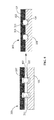
- the support members 301 include the same material as the substrate 101, and have a melting temperature above the brazing temperature of the braze material 107.
- the support members 301 are secured (step 320) in any suitable position within the groove 103 to reduce or eliminate slumping, sagging, and/or drooping of the braze material 107 into the groove 103. Suitable positions include, but are not limited to, side portions 303 of the groove 103, a top portion 305 of the groove 103, or a combination thereof.
- the third braze assembly 309 is applied (step 330) over the substrate 101.
- the third braze assembly 309 is shaped prior to applying (step 330) to conform with the shape of the substrate 101 so that the fluid flowing through the cooling microchannel 104 does not leak.
- at least one of the grooves 103 in the third braze assembly 309 is positioned to correspond with at least one of the grooves 103 in the substrate 101. Together, the corresponding grooves 103 between the third braze assembly 309 and the substrate 101 form the cooling microchannels 104.
- the third braze assembly 309 when the third braze assembly 309 is applied (step 330), at least one of the grooves 103 in the third braze assembly 309 is positioned such that it does not correspond with the at least one groove 103 in the substrate 101.
- Each non-corresponding groove 103 in either the substrate 101 or the third braze assembly 309 forms a separate microchannel 104.
- the substrate 101 does not include the grooves 103.
- Applying (step 330) the third braze assembly 309 over the substrate 101 without the grooves 103 permits the formation of the cooling microchannels 104 without forming the grooves 103 in the substrate 101.
- the support members 301 include a single metal form positioned and/or secured within the groove 103 in the braze material 107 to form the third braze assembly 309.
- the support member 301 is a microtube 311 positioned within the groove 103.
- the microtube 311 has a higher melting temperature than the braze material 107, and is secured (step 320) within the groove 103 during the brazing (step 340) of the third braze assembly 309 to the substrate 101.
- the microtube 311 secured within the groove 103 forms the microchannel 104 in the brazed article.
- the microtube 311 includes any suitable shape such as, but not limited to, circular, square, rectangular, triangular, any other polygonal shape, or a combination thereof. In another embodiment, the shape and/or size of the microtube 311 is varied along the length of the microtube 311.
- the support members 301 include any suitable material for maintaining the shape of the groove 103 during the brazing (step 340). Suitable materials include, but are not limited to, ceramics, metal alloys, or a combination thereof.
- the support members 301 include ceramic, and are not brazed (step 340) to the substrate 101 during the elevated temperature brazing (step 340).
- the support members 301 include metal alloys and both the braze material 107 of the third braze assembly 309 and the support members 301 are brazed (step 340) to the substrate 101 during the elevated temperature brazing (step 340).
Abstract
Description
- The present invention is directed to a brazing method. More specifically, the present invention is directed to brazing methods for forming cooling microchannels.
- Turbine systems are continuously being modified to increase efficiency and decrease cost. One method for increasing the efficiency of a turbine system includes increasing the operating temperature of the turbine system. To increase the temperature, the turbine system must be constructed of materials which can withstand such temperatures during continued use.
- In addition to modifying component materials and coatings, the temperature capability of a turbine component may be increased through the use of cooling microchannels. The cooling microchannels can be incorporated into metals and alloys used in high temperature regions of gas turbines. However, forming an exterior cover over the cooling microchannels can be difficult as thermal spraying directly over the channel can result in coating material filling the channel. One method to prevent the coating material from filling the channel includes filling the channel with a sacrificial material prior to coating, then coating the component and subsequently leeching out the sacrificial material. The filling and removing of the sacrificial material can be both difficult and expensive.
- As an alternative to filling and leeching, a thin cover layer can be brazed to the substrate, over the cooling microchannel. However, during the brazing of materials to a surface of the substrate, the brazing temperatures required to sufficiently braze the material may also soften the braze cover material. The softened material can sag or droop into the cooling microchannels, blocking them as they harden. As such, brazing requires a very narrow temperature range, outside of which the component can be damaged or made unusable.
- A brazing method that does not suffer from one or more of the above drawbacks would be desirable in the art.
- In one embodiment, a brazing method includes providing a substrate having at least one groove. Next, a support member is provided and positioned over the at least one groove in the substrate. A braze material is provided and applied over the support member, the support member and the braze material forming a first braze assembly. Next, the first braze assembly is heated to braze the first braze assembly to the substrate.
- In another exemplary embodiment, a brazing method includes providing a preform, providing a mesh, pressing the mesh into the preform, heating the preform to form a second braze assembly, providing a substrate, providing at least one groove in the substrate, applying the second braze assembly over the at least one groove in the substrate, then brazing the second braze assembly to the substrate.
- In another exemplary embodiment, a brazing method includes providing a braze material, forming at least one groove in the braze material, securing support members within the at least one groove to form a third braze assembly, providing a substrate, applying the third braze assembly over the substrate, and brazing the third braze assembly to the substrate to form a brazed article. The at least one groove in the third braze assembly forms at least one cooling microchannel in the brazed article.
- Other features and advantages of the present invention will be apparent from the following more detailed description of the preferred embodiment, taken in conjunction with the accompanying drawings which illustrate, by way of example, the principles of the invention.
-
-
FIG. 1 is a flow chart of a brazing method according to an embodiment of the disclosure. -
FIG. 2 is a process view of a brazing method according to an embodiment of the disclosure. -
FIG. 3 is a process view of a brazing method according to an embodiment of the disclosure. -
FIG. 4 is a flow chart of a brazing method according to an embodiment of the disclosure. -
FIG. 5 is a process view of a brazing method according to an embodiment of the disclosure. -
FIG. 6 is a flow chart of a brazing method according to an embodiment of the disclosure. -
FIG. 7 is a process view of a brazing method according to an embodiment of the disclosure. -
FIG. 8 is a process view of a brazing method according to an embodiment of the disclosure. -
FIG. 9 is a process view of a prior art brazing method showing a braze material forming a convex border within a groove in a substrate. - Wherever possible, the same reference numbers will be used throughout the drawings to represent the same parts.
- Provided is an exemplary brazing method. Embodiments of the present disclosure, in comparison to processes and articles not using one or more of the features disclosed herein, increase efficiency of cooling microchannel formation, decrease cost of cooling microchannel formation, decrease encroachment of braze material into cooling microchannels during brazing, permit increased brazing temperatures, decrease scrap rate during brazing, permit formation of cooling microchannels in the braze material, or a combination thereof.
- Referring to
FIG. 1 andFIG. 2 , in one embodiment, abrazing method 100 includes providing asubstrate 101 having at least onegroove 103, providing asupport member 105, positioning thesupport member 105 over thegroove 103 in the substrate 101 (step 110), providing abraze material 107, applying thebraze material 107 over the support member 105 (step 120) to form afirst braze assembly 109 comprising thesupport member 105 and thebraze material 107, and heating the first braze assembly 109 (step 130) to braze thefirst braze assembly 109 to thesubstrate 101. In another embodiment, thebraze material 107 may be formed with a thickness of up to 30 mils, up to 25 mils, up to 20 mils, or a combination thereof. The brazing is performed by any suitable braze method capable of securing thebraze material 107 of thefirst braze assembly 109 to thesubstrate 101 to form a brazed article. Each of the at least onegrooves 103 insubstrate 101 forms acooling microchannel 104 in the brazed article. Suitable braze methods include, but are not limited to, vacuum brazing, atmospheric brazing, brazing in a non-oxidizing atmosphere, or a combination thereof. Thebraze material 107 includes any suitable material such as, but not limited to, a nickel-based braze alloy. - Referring to
FIG. 3 , in one embodiment, thefirst braze assembly 109 also may be intermediate thesubstrate 101 having thegroove 103, and asecond substrate 102 comprising the same material. In this embodiment, not only does thefirst braze assembly 109 prevent sagging, slumping, or drooping of thebraze material 107 into thegroove 103, but thefirst braze assembly 109 joins thesubstrate 101 having thegroove 103 to thesecond substrate 102. Referring toFIG. 9 , sagging, slumping, or drooping, as used herein, refers to thebraze material 107 entering thegroove 103 and forming a convex border within thegroove 103. - During the heating of the first braze assembly 109 (step 130), a braze temperature softens the
braze material 107, which otherwise may sag, slump, or droop into thegroove 103 under its own weight without support. However, positioning of thesupport member 105 over the groove 103 (step 110) maintains thebraze material 107 above thegroove 103, minimizing, reducing, or eliminating the sagging, slumping, or drooping of thebraze material 107. Additionally, thesupport member 105 reduces or eliminates scrap formation from an application utilizing increased heat to thebraze material 107 by reducing or eliminating the sagging or drooping of thebraze material 107 into thegroove 103. Thesupport member 105 may be any suitable article capable of maintaining thebraze material 107 above thegroove 103 during the heating of the first braze assembly 109 (step 130). Suitable articles for thesupport member 105 include, but are not limited to, a rod, a wire, a mesh 201 (FIG. 2 ), a solid sheet, a perforated sheet, or a combination thereof. Thesupport member 105 preferably should have a sufficiently high melting temperature to survive brazing. However,support member 105 may be incorporated into the brazed article or may degrade within the brazed article during the life of the turbine. - The positioning of the
support member 105 over the groove 103 (step 110) to reduce or eliminate the slumping, sagging, or drooping of the softenedbraze material 107 permits brazing temperatures to be achieved without thebraze material 107 entering thegroove 103. In one embodiment, thesupport member 105 may be assimilated into thebraze material 107 by the increased brazing temperatures during the heating of the first braze assembly 109 (step 130). In one embodiment, thesupport member 105 has a higher melting and softening temperature than temperature of thebraze material 107 and is incorporated into a brazed article. Thesupport member 105 that can withstand the heating of the first braze assembly 109 (step 130) includes any suitable composition that is not softened at brazing temperatures. Suitable compositions include those that are similar or substantially similar to thesubstrate 101, such as, but not limited to, ceramics, metal alloys, or a combination thereof. Support members that may degrade include materials that may oxidize during high temperature turbine operations, such as steel. - The
cooling microchannel 104 forms between thesubstrate 101 and thefirst braze assembly 109. Thecooling microchannel 104 includes an open interior space to permit the flow of a fluid therein. Reducing or eliminating the sagging or drooping of the softenedbraze material 107 into the open interior space of thecooling microchannel 104 permits unimpeded flow of cooling fluid. In one embodiment, the coolingmicrochannel 104 includes a width and/or depth of, but not limited to, between about 5 mils and about 200 mils, between about 10 mils and about 150 mils, between about 10 mils and about 100 mils, or any combination, sub-combination, range, or sub-range thereof wherein one mil equals 0.001 inches. In another embodiment, the width and/or depth of thecooling microchannel 104 varies between channels or along the coolingmicrochannel 104 itself. In a further embodiment, the coolingmicrochannel 104 includes any suitable cross-sectional shape such as, but not limited to, a circle, a semi-circle, a square, a rectangle, an oval, a triangle, any other polygonal shape, or a combination thereof. - The
substrate 101 includes any component utilizing thecooling microchannel 104 therein such as, but not limited to, a bucket, a nozzle, a shroud, a hot gas path component, or combustor. In one embodiment, thefirst braze assembly 109 is shaped prior to heating (step 130) to conform with the shape of thesubstrate 101 so that the fluid flowing through the coolingmicrochannel 104 does not leak. The substrate includes any suitable brazeable composition such as, but not limited to, a nickel-based alloy, a cobalt-based alloy, a high-strength steel alloy, or a combination thereof. In a gas turbine, thesubstrate 101 having the coolingmicrochannel 104 is exposed to operational temperatures of between about 1600° F and about 2400° F, between about 1700° F and about 2300° F, between about 1800° F and about 2200° F, or any combination, sub-combination, range, or sub-range thereof. Providing thebraze material 107 having a similar or substantially similar coefficient of thermal expansion to the substrate may reduce stress from differential expansion during operation. - Referring to
FIG. 4 andFIG. 5 , in one embodiment, themesh 201 is pressed (step 210) into apreform 203 in a "green" state prior a sintering operation, then heated (step 220) to form asecond braze assembly 209. In another embodiment, themesh 201 is pressed (step 210) in between two (2) or more layers of thepreform 203 then heated (step 220) to form thesecond braze assembly 209. - In one embodiment, prior to heating (step 220), the
preform 203 in the "green" state forms a felt-type material. Thepreform 203 includes at least a high-melting alloy, a low-melting alloy, and a binder. In another embodiment, both the high-melting alloy and the low-melting alloy are in powdered form held together by the binder. Heating (step 220) of thepreform 203 sinters thepreform 203, volatilizing or burning the binder and securing the high-melting alloy, the low-melting alloy, and themesh 201 to each other. The heating (step 220) is performed at any suitable temperature below the brazing temperature of thepreform 203, but sufficiently high to coalesce the high-melt alloy powder and the low-melt alloy powder with minimal melting of the low-melt alloy. Additionally, in another embodiment, the heating (step 220) of thepreform 203 provides incipient melting of the low-melt alloy which provides for binding of the high melt alloy andmesh 201. Suitable temperatures include, but are not limited to, between about 1700° F and about 2200° F, between about 1800° F and about 2000° F, between about 1850° F and about 1950° F, or any combination, sub-combination, range, or sub-range thereof. The high-melting alloy may be similar or substantially similar to thesubstrate 101. The low-melting alloy includes materials which melt below the high-melting material or the substrate, for example around 2000° F. - In one embodiment, the low-melting alloy has a composition characterized by a nominal weight percentage of between about 8.0% and about 8.7% Cr, between about 9% and about 10% Co, between about 5.25% and about 5.75% Al, up to about 0.9% Ti (for example, between about 0.6% and about 0.9%), between about 9.3% and about 9.7% W, up to about 0.6% Mo (for example, between about 0.4% and about 0.6%), between about 2.8% and about 3.3% Ta, between about 1.3% and about 1.7% Hf, up to about 0.1% C (for example, between about 0.07% and about 0.1%), up to about 0.02% Zr (for example, between about 0.005% and about 0.02%), up to about 0.02% B (for example, between about 0.01% and about 0.02%), up to about 0.2% Fe, up to about 0.12% Si, up to about 0.1 % Mn, up to about 0.1 % Cu, up to about 0.01 % P, up to about 0.004% S, up to about 0.1% Nb, and a balance of nickel. In another embodiment, the low-melting alloy has a composition characterized by a nominal weight percentage of about 19.0 percent chromium, about 0.03 percent boron, about 10 percent silicon, about 0.1 percent carbon, and balance nickel.
- In one embodiment, the high-melting alloy has a composition characterized by a nominal weight percentage of about 12 percent cobalt, about 6.8 percent chromium, about 4.9 percent tungsten, about 1.5 percent molybdenum, about 6.1 percent aluminum, about 6.3 percent tantalum, about 0.12 percent carbon, about 2.8 percent rhenium, about 1.2 percent hafnium, and balance nickel.
- The
second braze assembly 209 is applied over thegroove 103 in the substrate 101 (step 230) and brazed (step 240) to thesubstrate 101. Themesh 201 increases the rigidity of thesecond braze assembly 209, reducing or eliminating slumping, sagging, and/or drooping into thegroove 103 during the brazing (step 240). The brazing (step 240) of thesecond braze assembly 209 over thegroove 103 forms a cover over the coolingmicrochannel 104 in thesubstrate 101. Themesh 201 remains within thesecond braze assembly 209 forming a portion of the brazed article, or is assimilated during the brazing or during subsequent operation of the turbine (step 240). In one embodiment, thesecond braze assembly 209 is shaped prior to brazing (step 240) to conform with the shape of thesubstrate 101 so that the fluid flowing through the coolingmicrochannel 104 does not leak. - Referring to
FIG. 6 andFIG. 7 , in one embodiment, at least one of thegrooves 103 is formed (step 310) in thebraze material 107 andsupport members 301 are secured (step 320) within thegroove 103 in thebraze material 107 to form athird braze assembly 309. In one embodiment, thesupport members 301 include the same material as thesubstrate 101, and have a melting temperature above the brazing temperature of thebraze material 107. Thesupport members 301 are secured (step 320) in any suitable position within thegroove 103 to reduce or eliminate slumping, sagging, and/or drooping of thebraze material 107 into thegroove 103. Suitable positions include, but are not limited to,side portions 303 of thegroove 103, atop portion 305 of thegroove 103, or a combination thereof. - After securing (step 320) the
support members 301 within thegroove 103, thethird braze assembly 309 is applied (step 330) over thesubstrate 101. Thethird braze assembly 309 is shaped prior to applying (step 330) to conform with the shape of thesubstrate 101 so that the fluid flowing through the coolingmicrochannel 104 does not leak. In one embodiment, when thethird braze assembly 309 is applied (step 330), at least one of thegrooves 103 in thethird braze assembly 309 is positioned to correspond with at least one of thegrooves 103 in thesubstrate 101. Together, the correspondinggrooves 103 between thethird braze assembly 309 and thesubstrate 101 form the coolingmicrochannels 104. In another embodiment, when thethird braze assembly 309 is applied (step 330), at least one of thegrooves 103 in thethird braze assembly 309 is positioned such that it does not correspond with the at least onegroove 103 in thesubstrate 101. Eachnon-corresponding groove 103 in either thesubstrate 101 or thethird braze assembly 309 forms aseparate microchannel 104. In an alternate embodiment, thesubstrate 101 does not include thegrooves 103. Applying (step 330) thethird braze assembly 309 over thesubstrate 101 without thegrooves 103 permits the formation of the coolingmicrochannels 104 without forming thegrooves 103 in thesubstrate 101. - Referring to
FIG. 8 , in an alternate embodiment, thesupport members 301 include a single metal form positioned and/or secured within thegroove 103 in thebraze material 107 to form thethird braze assembly 309. For example, in one embodiment, thesupport member 301 is amicrotube 311 positioned within thegroove 103. Themicrotube 311 has a higher melting temperature than thebraze material 107, and is secured (step 320) within thegroove 103 during the brazing (step 340) of thethird braze assembly 309 to thesubstrate 101. Themicrotube 311 secured within thegroove 103 forms themicrochannel 104 in the brazed article. Themicrotube 311 includes any suitable shape such as, but not limited to, circular, square, rectangular, triangular, any other polygonal shape, or a combination thereof. In another embodiment, the shape and/or size of themicrotube 311 is varied along the length of themicrotube 311. - The
support members 301 include any suitable material for maintaining the shape of thegroove 103 during the brazing (step 340). Suitable materials include, but are not limited to, ceramics, metal alloys, or a combination thereof. For example, in one embodiment, thesupport members 301 include ceramic, and are not brazed (step 340) to thesubstrate 101 during the elevated temperature brazing (step 340). In another example, thesupport members 301 include metal alloys and both thebraze material 107 of thethird braze assembly 309 and thesupport members 301 are brazed (step 340) to thesubstrate 101 during the elevated temperature brazing (step 340). - While the invention has been described with reference to a preferred embodiment, it will be understood by those skilled in the art that various changes may be made and equivalents may be substituted for elements thereof without departing from the scope of the invention. In addition, many modifications may be made to adapt a particular situation or material to the teachings of the invention without departing from the essential scope thereof. Therefore, it is intended that the invention not be limited to the particular embodiment disclosed as the best mode contemplated for carrying out this invention, but that the invention will include all embodiments falling within the scope of the appended claims.
Claims (15)
- A brazing method, comprising:providing a substrate having at least one groove;providing a support member;positioning the support member over the at least one groove in the substrate;providing a braze material;applying the braze material over the support member, the braze material and the support member forming a first braze assembly; andheating the first braze assembly to braze the first braze assembly to the substrate.
- The brazing method of claim 1, comprising maintaining the braze material above the at least one groove without the braze material entering the groove and forming a convex border.
- The brazing method of claim 1 or claim 2, further comprising the steps of:providing a second substrate; andpositioning the second substrate over the first braze assembly so that the first braze assembly is intermediate the substrate having the at least one groove and the second substrate;wherein the heating step brazes the second substrate to the substrate having the at least one groove.
- The brazing method of any preceding claim, wherein each of the at least one grooves forms a cooling microchannel with unimpeded flow between the substrate and the braze assembly.
- The brazing method of any preceding claim, wherein the braze material comprises a nickel-based braze alloy.
- The brazing method of any preceding claim, wherein the braze material includes a coefficient of thermal expansion compatible with the coefficient of thermal expansion of the substrate.
- The brazing method of any preceding claim, wherein the support member is a wire or a mesh.
- The brazing method of any preceding claim, further comprising:providing a preform from a high-melting alloy, a low-melting alloy, and a binder; andapplying the preform over the support member to form the first braze assembly.
- The brazing method of claim 8, wherein heating the first braze assembly sinters the preform and brazes the first braze assembly to the substrate.
- The brazing method of any preceding claim, wherein the substrate comprises a nickel-based alloy or a cobalt-based alloy.
- A brazing method, comprising:providing a preform;providing a mesh;pressing the mesh into the preform;heating the preform to form a second braze assembly;providing a substrate;providing at least one groove in the substrate;applying the second braze assembly over the at least one groove in the substrate; thenbrazing the second braze assembly to the substrate.
- A brazing method, comprising:providing a braze material;forming at least one groove in the braze material;securing support members within the at least one groove to form a third braze assembly;providing a substrate;applying the third braze assembly over the substrate; andbrazing the third braze assembly to the substrate to form a brazed article;wherein each of the at least one grooves forms a cooling microchannel in the brazed article.
- The brazing method of claim 12, wherein the support members are ceramics.
- The brazing method of claim 12 or claim 13, wherein the support members are microtubes.
- The brazing method of claim 14, wherein the microtube forms the microchannel in the brazed article.
Applications Claiming Priority (1)
| Application Number | Priority Date | Filing Date | Title |
|---|---|---|---|
| US14/041,701 US9126279B2 (en) | 2013-09-30 | 2013-09-30 | Brazing method |
Publications (2)
| Publication Number | Publication Date |
|---|---|
| EP2857134A1 true EP2857134A1 (en) | 2015-04-08 |
| EP2857134B1 EP2857134B1 (en) | 2016-12-21 |
Family
ID=51570350
Family Applications (1)
| Application Number | Title | Priority Date | Filing Date |
|---|---|---|---|
| EP14185440.6A Active EP2857134B1 (en) | 2013-09-30 | 2014-09-18 | Brazing method |
Country Status (5)
| Country | Link |
|---|---|
| US (3) | US9126279B2 (en) |
| EP (1) | EP2857134B1 (en) |
| JP (1) | JP6635650B2 (en) |
| CN (1) | CN104511674B (en) |
| HU (1) | HUE032321T2 (en) |
Cited By (1)
| Publication number | Priority date | Publication date | Assignee | Title |
|---|---|---|---|---|
| DE102016214742A1 (en) * | 2016-08-09 | 2018-02-15 | Siemens Aktiengesellschaft | Method for joining materials and composite material |
Families Citing this family (16)
| Publication number | Priority date | Publication date | Assignee | Title |
|---|---|---|---|---|
| US9254537B2 (en) | 2013-12-19 | 2016-02-09 | Siemens Energy, Inc. | Plural layer putty-powder/slurry application method for superalloy component crack vacuum furnace healing |
| US10364195B2 (en) | 2014-07-28 | 2019-07-30 | Rolls-Royce Corporation | Braze for ceramic and ceramic matrix composite components |
| US9909197B2 (en) * | 2014-12-22 | 2018-03-06 | Semes Co., Ltd. | Supporting unit and substrate treating apparatus including the same |
| US10293424B2 (en) * | 2015-05-05 | 2019-05-21 | Rolls-Royce Corporation | Braze for ceramic and ceramic matrix composite components |
| EP3095550A1 (en) | 2015-05-20 | 2016-11-23 | Rolls-Royce Corporation | Pre-sintered preform braze for joining alloy castings and use thereof |
| US10767501B2 (en) * | 2016-04-21 | 2020-09-08 | General Electric Company | Article, component, and method of making a component |
| US10975719B2 (en) * | 2017-01-05 | 2021-04-13 | General Electric Company | Process and printed article |
| US20190035612A1 (en) * | 2017-07-26 | 2019-01-31 | Suranjan Dabare | Sputtering target with micro channels |
| EP3501727B1 (en) * | 2017-12-22 | 2021-02-03 | Ansaldo Energia IP UK Limited | Thermal protection method for gas turbine components |
| EP3815066B1 (en) | 2018-06-29 | 2023-03-01 | Carrier Corporation | Multipurpose air monitoring device |
| US11090771B2 (en) | 2018-11-05 | 2021-08-17 | Rolls-Royce Corporation | Dual-walled components for a gas turbine engine |
| US11517969B2 (en) * | 2019-01-24 | 2022-12-06 | General Electric Company | Weld-brazing techniques |
| US11305363B2 (en) | 2019-02-11 | 2022-04-19 | Rolls-Royce Corporation | Repair of through-hole damage using braze sintered preform |
| US11859818B2 (en) | 2019-02-25 | 2024-01-02 | General Electric Company | Systems and methods for variable microchannel combustor liner cooling |
| CN113751966B (en) * | 2021-08-25 | 2022-07-26 | 西安远航真空钎焊技术有限公司 | Thin-wall part runner forming method based on vacuum brazing |
| US11692446B2 (en) | 2021-09-23 | 2023-07-04 | Rolls-Royce North American Technologies, Inc. | Airfoil with sintered powder components |
Citations (4)
| Publication number | Priority date | Publication date | Assignee | Title |
|---|---|---|---|---|
| US5848083A (en) * | 1996-10-24 | 1998-12-08 | Sdl, Inc. | Expansion-matched high-thermal-conductivity stress-relieved mounting modules |
| JP2010194578A (en) * | 2009-02-25 | 2010-09-09 | Mitsubishi Heavy Ind Ltd | Method for producing laminated heat resistant alloy plate |
| JP2010274311A (en) * | 2009-05-29 | 2010-12-09 | Mitsubishi Heavy Ind Ltd | Method for producing planar body, method for producing combustion tube, gas turbine combustor and gas turbine |
| US20130095342A1 (en) * | 2011-10-14 | 2013-04-18 | General Electric Company | Brazing process, braze assembly, and brazed article |
Family Cites Families (46)
| Publication number | Priority date | Publication date | Assignee | Title |
|---|---|---|---|---|
| US2392886A (en) * | 1940-02-15 | 1946-01-15 | Weatherhead Co | Method of copper brazing |
| US2648520A (en) * | 1949-08-02 | 1953-08-11 | Heinz E Schmitt | Air-cooled turbine blade |
| US3657789A (en) * | 1968-03-29 | 1972-04-25 | Francis Anglade | Apparatus for preparing a microelement for soldering |
| US4040159A (en) * | 1975-10-29 | 1977-08-09 | General Electric Company | Method of manufacture of cooled airfoil-shaped bucket |
| DE2844888C2 (en) * | 1978-10-14 | 1983-02-24 | W.C. Heraeus Gmbh, 6450 Hanau | Raw material for the production of electrical contacts |
| JPS6137395A (en) * | 1984-07-31 | 1986-02-22 | Sumitomo Light Metal Ind Ltd | Aluminum alloy brazing filler metal for aluminum heat exchanger |
| US4843693A (en) * | 1986-05-19 | 1989-07-04 | John Chisholm | Method of making a crimped wire mesh heat exchanger/sink |
| US5332360A (en) * | 1993-09-08 | 1994-07-26 | General Electric Company | Stator vane having reinforced braze joint |
| DE69732397T2 (en) * | 1996-04-10 | 2006-01-26 | GE Accessory Services, Inc., Cincinnati | COATING PROCESS, COATING AND ARTICLES COATED THEREFOR |
| ATE276843T1 (en) * | 1996-06-26 | 2004-10-15 | Showa Denko Kk | METHOD FOR PRODUCING FLAT TUBES FOR HEAT EXCHANGERS |
| JP3202636B2 (en) * | 1997-02-12 | 2001-08-27 | 東北電力株式会社 | Cooling wall structure of steam-cooled combustor |
| DE19801374C1 (en) * | 1998-01-16 | 1999-03-11 | Dbb Fuel Cell Engines Gmbh | Method for soldering micro structured sheet metal elements |
| MXPA01007647A (en) * | 1999-01-29 | 2002-07-02 | Norsk Hydro As | Manifold for heat exchanger. |
| US6395995B1 (en) * | 2000-03-15 | 2002-05-28 | Intel Corporation | Apparatus for coupling integrated circuit packages to bonding pads having vias |
| DE10030776C2 (en) * | 2000-06-23 | 2002-06-20 | Mtu Aero Engines Gmbh | Process for the repair of metallic components, in particular for gas turbines |
| US6402464B1 (en) * | 2000-08-29 | 2002-06-11 | General Electric Company | Enhanced heat transfer surface for cast-in-bump-covered cooling surfaces and methods of enhancing heat transfer |
| US6367686B1 (en) * | 2000-08-31 | 2002-04-09 | United Technologies Corporation | Self cleaning braze material |
| US6530971B1 (en) * | 2001-01-29 | 2003-03-11 | General Electric Company | Nickel-base braze material and braze repair method |
| US6871774B2 (en) * | 2002-01-04 | 2005-03-29 | Triumph Brands, Inc. | Aluminum tubular heat exchanger and method of construction |
| JP3891346B2 (en) * | 2002-01-07 | 2007-03-14 | 千住金属工業株式会社 | Fine copper ball and method for producing fine copper ball |
| DE10392500B4 (en) * | 2002-04-01 | 2010-02-25 | Nas Interplex, Inc. | Solder-carrying component and method for holding a solder mass thereon |
| US6708870B2 (en) * | 2002-05-24 | 2004-03-23 | Praxair S.T. Technology, Inc. | Method for forming sputter target assemblies |
| FR2850741B1 (en) * | 2003-01-30 | 2005-09-23 | Snecma Propulsion Solide | PROCESS FOR MANUFACTURING AN ACTIVE COOLING PANEL OF THERMOSTRUCTURAL COMPOSITE MATERIAL |
| US7014426B2 (en) * | 2003-02-14 | 2006-03-21 | General Motors Corporation | Brazed aluminum turbine for an automotive transmission and method thereof |
| US7410088B2 (en) * | 2003-09-05 | 2008-08-12 | Matsushita Electric Industrial, Co., Ltd. | Solder preform for low heat stress laser solder attachment |
| CN100377343C (en) * | 2004-09-21 | 2008-03-26 | 鸿富锦精密工业(深圳)有限公司 | Manufacturing method of heat radiation device |
| US20070141375A1 (en) * | 2005-12-20 | 2007-06-21 | Budinger David E | Braze cladding for direct metal laser sintered materials |
| US7658315B2 (en) * | 2006-01-09 | 2010-02-09 | General Electric Company | Process of brazing superalloy components |
| EP1857218A1 (en) * | 2006-05-18 | 2007-11-21 | Siemens Aktiengesellschaft | Method for repairing a component and a component |
| US7695247B1 (en) | 2006-09-01 | 2010-04-13 | Florida Turbine Technologies, Inc. | Turbine blade platform with near-wall cooling |
| US7740442B2 (en) | 2006-11-30 | 2010-06-22 | General Electric Company | Methods and system for cooling integral turbine nozzle and shroud assemblies |
| CN100453233C (en) * | 2006-12-20 | 2009-01-21 | 中国电子科技集团公司第十四研究所 | Furnace braze welding process of 6063 aluminum alloy micro-channel cooling plate |
| US20110180199A1 (en) * | 2007-04-17 | 2011-07-28 | United Technologies Corporation | Powder -metallurgy braze preform and method of use |
| US7857589B1 (en) | 2007-09-21 | 2010-12-28 | Florida Turbine Technologies, Inc. | Turbine airfoil with near-wall cooling |
| JP5078537B2 (en) * | 2007-10-15 | 2012-11-21 | 三菱重工業株式会社 | Repair method |
| EP2196276A1 (en) * | 2008-12-15 | 2010-06-16 | Siemens Aktiengesellschaft | Form bodies for welding, assembly of form bodies, method and component |
| JP5578864B2 (en) * | 2010-01-20 | 2014-08-27 | 三菱重工業株式会社 | Repair method of wall member with flow path |
| EP2353763A1 (en) * | 2010-02-10 | 2011-08-10 | Siemens Aktiengesellschaft | A method of manufacturing a hot-gas component with a cooling channel by brazing a sintered sheet on a carrier ;corresponding hot-gas component |
| DE102010031468A1 (en) * | 2010-07-16 | 2012-01-19 | Behr Gmbh & Co. Kg | Fluid channel for a heat exchanger |
| US9623504B2 (en) * | 2010-11-08 | 2017-04-18 | General Electric Company | System and method for brazing |
| CH705321A1 (en) * | 2011-07-19 | 2013-01-31 | Alstom Technology Ltd | Solder foil for high-temperature soldering and method of repairing or manufacturing components using this solder film. |
| US20130156555A1 (en) * | 2011-12-15 | 2013-06-20 | General Electric Company | Braze materials, brazing processes, and components with wear-resistant coatings formed thereby |
| US9227259B2 (en) * | 2012-08-22 | 2016-01-05 | International Business Machines Corporation | Increasing the efficiency of solar cells by transfer of solder |
| US20140170433A1 (en) * | 2012-12-19 | 2014-06-19 | General Electric Company | Components with near-surface cooling microchannels and methods for providing the same |
| US10315264B2 (en) * | 2013-01-29 | 2019-06-11 | General Electric Company | Joining process and joined article |
| US9056443B2 (en) * | 2013-02-04 | 2015-06-16 | General Electric Company | Brazing process, braze arrangement, and brazed article |
-
2013
- 2013-09-30 US US14/041,701 patent/US9126279B2/en active Active
-
2014
- 2014-09-18 EP EP14185440.6A patent/EP2857134B1/en active Active
- 2014-09-18 HU HUE14185440A patent/HUE032321T2/en unknown
- 2014-09-29 JP JP2014197704A patent/JP6635650B2/en active Active
- 2014-09-29 CN CN201410511129.9A patent/CN104511674B/en active Active
-
2015
- 2015-08-20 US US14/831,485 patent/US9498834B2/en not_active Expired - Fee Related
- 2015-08-20 US US14/831,581 patent/US9498835B2/en not_active Expired - Fee Related
Patent Citations (4)
| Publication number | Priority date | Publication date | Assignee | Title |
|---|---|---|---|---|
| US5848083A (en) * | 1996-10-24 | 1998-12-08 | Sdl, Inc. | Expansion-matched high-thermal-conductivity stress-relieved mounting modules |
| JP2010194578A (en) * | 2009-02-25 | 2010-09-09 | Mitsubishi Heavy Ind Ltd | Method for producing laminated heat resistant alloy plate |
| JP2010274311A (en) * | 2009-05-29 | 2010-12-09 | Mitsubishi Heavy Ind Ltd | Method for producing planar body, method for producing combustion tube, gas turbine combustor and gas turbine |
| US20130095342A1 (en) * | 2011-10-14 | 2013-04-18 | General Electric Company | Brazing process, braze assembly, and brazed article |
Cited By (1)
| Publication number | Priority date | Publication date | Assignee | Title |
|---|---|---|---|---|
| DE102016214742A1 (en) * | 2016-08-09 | 2018-02-15 | Siemens Aktiengesellschaft | Method for joining materials and composite material |
Also Published As
| Publication number | Publication date |
|---|---|
| US20150352650A1 (en) | 2015-12-10 |
| US20150090773A1 (en) | 2015-04-02 |
| US20150352651A1 (en) | 2015-12-10 |
| CN104511674B (en) | 2018-12-04 |
| EP2857134B1 (en) | 2016-12-21 |
| JP6635650B2 (en) | 2020-01-29 |
| US9498835B2 (en) | 2016-11-22 |
| CN104511674A (en) | 2015-04-15 |
| JP2015110246A (en) | 2015-06-18 |
| HUE032321T2 (en) | 2017-09-28 |
| US9126279B2 (en) | 2015-09-08 |
| US9498834B2 (en) | 2016-11-22 |
Similar Documents
| Publication | Publication Date | Title |
|---|---|---|
| US9498835B2 (en) | Brazing method | |
| JP6605853B2 (en) | Fiber reinforced brazing method | |
| EP2808113B1 (en) | Hybrid diffusion-brazing process | |
| JP7358034B2 (en) | How to make pre-sintered preforms | |
| US9931814B2 (en) | Article and method for making an article | |
| US20150068629A1 (en) | Three-dimensional printing process, swirling device and thermal management process | |
| EP3072612A2 (en) | Component and method for fabricating a component | |
| US9931695B2 (en) | Article and method for making an article | |
| EP2497596A2 (en) | Method of fabricating a component and a component | |
| JP2016014390A (en) | Braze methods for turbine buckets, and components for turbine buckets | |
| JP2016040048A (en) | Braze methods and components with heat resistant materials | |
| EP3536433A1 (en) | Techniques and assemblies for joining components | |
| JP2018167324A (en) | Brazing method and brazed article | |
| EP3247521B1 (en) | A heat exchanger comprising micro channels and manufacturing thereof | |
| JP7229994B2 (en) | Pre-sintered preforms and processes | |
| JP7076948B2 (en) | Articles, components, and methods of making components |
Legal Events
| Date | Code | Title | Description |
|---|---|---|---|
| PUAI | Public reference made under article 153(3) epc to a published international application that has entered the european phase |
Free format text: ORIGINAL CODE: 0009012 |
|
| 17P | Request for examination filed |
Effective date: 20140918 |
|
| AK | Designated contracting states |
Kind code of ref document: A1 Designated state(s): AL AT BE BG CH CY CZ DE DK EE ES FI FR GB GR HR HU IE IS IT LI LT LU LV MC MK MT NL NO PL PT RO RS SE SI SK SM TR |
|
| AX | Request for extension of the european patent |
Extension state: BA ME |
|
| R17P | Request for examination filed (corrected) |
Effective date: 20151008 |
|
| RBV | Designated contracting states (corrected) |
Designated state(s): AL AT BE BG CH CY CZ DE DK EE ES FI FR GB GR HR HU IE IS IT LI LT LU LV MC MK MT NL NO PL PT RO RS SE SI SK SM TR |
|
| RIC1 | Information provided on ipc code assigned before grant |
Ipc: B23K 1/00 20060101AFI20160502BHEP Ipc: B23K 1/19 20060101ALI20160502BHEP Ipc: B23K 1/20 20060101ALI20160502BHEP Ipc: B23K 101/00 20060101ALI20160502BHEP |
|
| GRAP | Despatch of communication of intention to grant a patent |
Free format text: ORIGINAL CODE: EPIDOSNIGR1 |
|
| INTG | Intention to grant announced |
Effective date: 20160713 |
|
| GRAS | Grant fee paid |
Free format text: ORIGINAL CODE: EPIDOSNIGR3 |
|
| GRAA | (expected) grant |
Free format text: ORIGINAL CODE: 0009210 |
|
| AK | Designated contracting states |
Kind code of ref document: B1 Designated state(s): AL AT BE BG CH CY CZ DE DK EE ES FI FR GB GR HR HU IE IS IT LI LT LU LV MC MK MT NL NO PL PT RO RS SE SI SK SM TR |
|
| REG | Reference to a national code |
Ref country code: GB Ref legal event code: FG4D |
|
| REG | Reference to a national code |
Ref country code: CH Ref legal event code: EP |
|
| REG | Reference to a national code |
Ref country code: IE Ref legal event code: FG4D |
|
| REG | Reference to a national code |
Ref country code: AT Ref legal event code: REF Ref document number: 855042 Country of ref document: AT Kind code of ref document: T Effective date: 20170115 |
|
| REG | Reference to a national code |
Ref country code: DE Ref legal event code: R096 Ref document number: 602014005617 Country of ref document: DE |
|
| PG25 | Lapsed in a contracting state [announced via postgrant information from national office to epo] |
Ref country code: LV Free format text: LAPSE BECAUSE OF FAILURE TO SUBMIT A TRANSLATION OF THE DESCRIPTION OR TO PAY THE FEE WITHIN THE PRESCRIBED TIME-LIMIT Effective date: 20161221 |
|
| REG | Reference to a national code |
Ref country code: LT Ref legal event code: MG4D |
|
| REG | Reference to a national code |
Ref country code: NL Ref legal event code: MP Effective date: 20161221 |
|
| PG25 | Lapsed in a contracting state [announced via postgrant information from national office to epo] |
Ref country code: NO Free format text: LAPSE BECAUSE OF FAILURE TO SUBMIT A TRANSLATION OF THE DESCRIPTION OR TO PAY THE FEE WITHIN THE PRESCRIBED TIME-LIMIT Effective date: 20170321 Ref country code: SE Free format text: LAPSE BECAUSE OF FAILURE TO SUBMIT A TRANSLATION OF THE DESCRIPTION OR TO PAY THE FEE WITHIN THE PRESCRIBED TIME-LIMIT Effective date: 20161221 Ref country code: LT Free format text: LAPSE BECAUSE OF FAILURE TO SUBMIT A TRANSLATION OF THE DESCRIPTION OR TO PAY THE FEE WITHIN THE PRESCRIBED TIME-LIMIT Effective date: 20161221 |
|
| REG | Reference to a national code |
Ref country code: AT Ref legal event code: MK05 Ref document number: 855042 Country of ref document: AT Kind code of ref document: T Effective date: 20161221 |
|
| PG25 | Lapsed in a contracting state [announced via postgrant information from national office to epo] |
Ref country code: HR Free format text: LAPSE BECAUSE OF FAILURE TO SUBMIT A TRANSLATION OF THE DESCRIPTION OR TO PAY THE FEE WITHIN THE PRESCRIBED TIME-LIMIT Effective date: 20161221 Ref country code: FI Free format text: LAPSE BECAUSE OF FAILURE TO SUBMIT A TRANSLATION OF THE DESCRIPTION OR TO PAY THE FEE WITHIN THE PRESCRIBED TIME-LIMIT Effective date: 20161221 Ref country code: RS Free format text: LAPSE BECAUSE OF FAILURE TO SUBMIT A TRANSLATION OF THE DESCRIPTION OR TO PAY THE FEE WITHIN THE PRESCRIBED TIME-LIMIT Effective date: 20161221 |
|
| PG25 | Lapsed in a contracting state [announced via postgrant information from national office to epo] |
Ref country code: NL Free format text: LAPSE BECAUSE OF FAILURE TO SUBMIT A TRANSLATION OF THE DESCRIPTION OR TO PAY THE FEE WITHIN THE PRESCRIBED TIME-LIMIT Effective date: 20161221 |
|
| PG25 | Lapsed in a contracting state [announced via postgrant information from national office to epo] |
Ref country code: CZ Free format text: LAPSE BECAUSE OF FAILURE TO SUBMIT A TRANSLATION OF THE DESCRIPTION OR TO PAY THE FEE WITHIN THE PRESCRIBED TIME-LIMIT Effective date: 20161221 Ref country code: EE Free format text: LAPSE BECAUSE OF FAILURE TO SUBMIT A TRANSLATION OF THE DESCRIPTION OR TO PAY THE FEE WITHIN THE PRESCRIBED TIME-LIMIT Effective date: 20161221 Ref country code: SK Free format text: LAPSE BECAUSE OF FAILURE TO SUBMIT A TRANSLATION OF THE DESCRIPTION OR TO PAY THE FEE WITHIN THE PRESCRIBED TIME-LIMIT Effective date: 20161221 Ref country code: IS Free format text: LAPSE BECAUSE OF FAILURE TO SUBMIT A TRANSLATION OF THE DESCRIPTION OR TO PAY THE FEE WITHIN THE PRESCRIBED TIME-LIMIT Effective date: 20170421 Ref country code: RO Free format text: LAPSE BECAUSE OF FAILURE TO SUBMIT A TRANSLATION OF THE DESCRIPTION OR TO PAY THE FEE WITHIN THE PRESCRIBED TIME-LIMIT Effective date: 20161221 |
|
| REG | Reference to a national code |
Ref country code: GR Ref legal event code: EP Ref document number: 20170400893 Country of ref document: GR Effective date: 20170804 |
|
| PG25 | Lapsed in a contracting state [announced via postgrant information from national office to epo] |
Ref country code: PL Free format text: LAPSE BECAUSE OF FAILURE TO SUBMIT A TRANSLATION OF THE DESCRIPTION OR TO PAY THE FEE WITHIN THE PRESCRIBED TIME-LIMIT Effective date: 20161221 Ref country code: BG Free format text: LAPSE BECAUSE OF FAILURE TO SUBMIT A TRANSLATION OF THE DESCRIPTION OR TO PAY THE FEE WITHIN THE PRESCRIBED TIME-LIMIT Effective date: 20170321 Ref country code: PT Free format text: LAPSE BECAUSE OF FAILURE TO SUBMIT A TRANSLATION OF THE DESCRIPTION OR TO PAY THE FEE WITHIN THE PRESCRIBED TIME-LIMIT Effective date: 20170421 Ref country code: SM Free format text: LAPSE BECAUSE OF FAILURE TO SUBMIT A TRANSLATION OF THE DESCRIPTION OR TO PAY THE FEE WITHIN THE PRESCRIBED TIME-LIMIT Effective date: 20161221 Ref country code: ES Free format text: LAPSE BECAUSE OF FAILURE TO SUBMIT A TRANSLATION OF THE DESCRIPTION OR TO PAY THE FEE WITHIN THE PRESCRIBED TIME-LIMIT Effective date: 20161221 Ref country code: AT Free format text: LAPSE BECAUSE OF FAILURE TO SUBMIT A TRANSLATION OF THE DESCRIPTION OR TO PAY THE FEE WITHIN THE PRESCRIBED TIME-LIMIT Effective date: 20161221 Ref country code: BE Free format text: LAPSE BECAUSE OF FAILURE TO SUBMIT A TRANSLATION OF THE DESCRIPTION OR TO PAY THE FEE WITHIN THE PRESCRIBED TIME-LIMIT Effective date: 20161221 |
|
| REG | Reference to a national code |
Ref country code: DE Ref legal event code: R097 Ref document number: 602014005617 Country of ref document: DE |
|
| REG | Reference to a national code |
Ref country code: FR Ref legal event code: PLFP Year of fee payment: 4 |
|
| REG | Reference to a national code |
Ref country code: HU Ref legal event code: AG4A Ref document number: E032321 Country of ref document: HU |
|
| PLBE | No opposition filed within time limit |
Free format text: ORIGINAL CODE: 0009261 |
|
| STAA | Information on the status of an ep patent application or granted ep patent |
Free format text: STATUS: NO OPPOSITION FILED WITHIN TIME LIMIT |
|
| 26N | No opposition filed |
Effective date: 20170922 |
|
| PG25 | Lapsed in a contracting state [announced via postgrant information from national office to epo] |
Ref country code: DK Free format text: LAPSE BECAUSE OF FAILURE TO SUBMIT A TRANSLATION OF THE DESCRIPTION OR TO PAY THE FEE WITHIN THE PRESCRIBED TIME-LIMIT Effective date: 20161221 |
|
| PG25 | Lapsed in a contracting state [announced via postgrant information from national office to epo] |
Ref country code: SI Free format text: LAPSE BECAUSE OF FAILURE TO SUBMIT A TRANSLATION OF THE DESCRIPTION OR TO PAY THE FEE WITHIN THE PRESCRIBED TIME-LIMIT Effective date: 20161221 |
|
| PG25 | Lapsed in a contracting state [announced via postgrant information from national office to epo] |
Ref country code: MC Free format text: LAPSE BECAUSE OF FAILURE TO SUBMIT A TRANSLATION OF THE DESCRIPTION OR TO PAY THE FEE WITHIN THE PRESCRIBED TIME-LIMIT Effective date: 20161221 |
|
| REG | Reference to a national code |
Ref country code: IE Ref legal event code: MM4A |
|
| PG25 | Lapsed in a contracting state [announced via postgrant information from national office to epo] |
Ref country code: LU Free format text: LAPSE BECAUSE OF NON-PAYMENT OF DUE FEES Effective date: 20170918 |
|
| PG25 | Lapsed in a contracting state [announced via postgrant information from national office to epo] |
Ref country code: IE Free format text: LAPSE BECAUSE OF NON-PAYMENT OF DUE FEES Effective date: 20170918 |
|
| REG | Reference to a national code |
Ref country code: FR Ref legal event code: PLFP Year of fee payment: 5 |
|
| PG25 | Lapsed in a contracting state [announced via postgrant information from national office to epo] |
Ref country code: MT Free format text: LAPSE BECAUSE OF NON-PAYMENT OF DUE FEES Effective date: 20170918 |
|
| PGFP | Annual fee paid to national office [announced via postgrant information from national office to epo] |
Ref country code: TR Payment date: 20180731 Year of fee payment: 8 Ref country code: CH Payment date: 20180828 Year of fee payment: 5 |
|
| PG25 | Lapsed in a contracting state [announced via postgrant information from national office to epo] |
Ref country code: CY Free format text: LAPSE BECAUSE OF FAILURE TO SUBMIT A TRANSLATION OF THE DESCRIPTION OR TO PAY THE FEE WITHIN THE PRESCRIBED TIME-LIMIT Effective date: 20161221 |
|
| PG25 | Lapsed in a contracting state [announced via postgrant information from national office to epo] |
Ref country code: MK Free format text: LAPSE BECAUSE OF FAILURE TO SUBMIT A TRANSLATION OF THE DESCRIPTION OR TO PAY THE FEE WITHIN THE PRESCRIBED TIME-LIMIT Effective date: 20161221 |
|
| PG25 | Lapsed in a contracting state [announced via postgrant information from national office to epo] |
Ref country code: TR Free format text: LAPSE BECAUSE OF FAILURE TO SUBMIT A TRANSLATION OF THE DESCRIPTION OR TO PAY THE FEE WITHIN THE PRESCRIBED TIME-LIMIT Effective date: 20161221 |
|
| REG | Reference to a national code |
Ref country code: CH Ref legal event code: PL |
|
| PG25 | Lapsed in a contracting state [announced via postgrant information from national office to epo] |
Ref country code: CH Free format text: LAPSE BECAUSE OF NON-PAYMENT OF DUE FEES Effective date: 20190930 Ref country code: GR Free format text: LAPSE BECAUSE OF NON-PAYMENT OF DUE FEES Effective date: 20200416 Ref country code: LI Free format text: LAPSE BECAUSE OF NON-PAYMENT OF DUE FEES Effective date: 20190930 Ref country code: AL Free format text: LAPSE BECAUSE OF FAILURE TO SUBMIT A TRANSLATION OF THE DESCRIPTION OR TO PAY THE FEE WITHIN THE PRESCRIBED TIME-LIMIT Effective date: 20161221 |
|
| PG25 | Lapsed in a contracting state [announced via postgrant information from national office to epo] |
Ref country code: FR Free format text: LAPSE BECAUSE OF NON-PAYMENT OF DUE FEES Effective date: 20190930 |
|
| PGFP | Annual fee paid to national office [announced via postgrant information from national office to epo] |
Ref country code: GB Payment date: 20220818 Year of fee payment: 9 |
|
| PGFP | Annual fee paid to national office [announced via postgrant information from national office to epo] |
Ref country code: HU Payment date: 20220823 Year of fee payment: 9 |
|
| PGFP | Annual fee paid to national office [announced via postgrant information from national office to epo] |
Ref country code: IT Payment date: 20230822 Year of fee payment: 10 |
|
| REG | Reference to a national code |
Ref country code: DE Ref legal event code: R081 Ref document number: 602014005617 Country of ref document: DE Owner name: GENERAL ELECTRIC TECHNOLOGY GMBH, CH Free format text: FORMER OWNER: GENERAL ELECTRIC COMPANY, SCHENECTADY, NY, US |
|
| PGFP | Annual fee paid to national office [announced via postgrant information from national office to epo] |
Ref country code: DE Payment date: 20230822 Year of fee payment: 10 |