EP2856898A1 - Adjustment device for sports footwear - Google Patents
Adjustment device for sports footwear Download PDFInfo
- Publication number
- EP2856898A1 EP2856898A1 EP20140179967 EP14179967A EP2856898A1 EP 2856898 A1 EP2856898 A1 EP 2856898A1 EP 20140179967 EP20140179967 EP 20140179967 EP 14179967 A EP14179967 A EP 14179967A EP 2856898 A1 EP2856898 A1 EP 2856898A1
- Authority
- EP
- European Patent Office
- Prior art keywords
- support member
- elements
- rotation
- guide
- sports footwear
- Prior art date
- Legal status (The legal status is an assumption and is not a legal conclusion. Google has not performed a legal analysis and makes no representation as to the accuracy of the status listed.)
- Withdrawn
Links
Images


Classifications
-
- A—HUMAN NECESSITIES
- A43—FOOTWEAR
- A43B—CHARACTERISTIC FEATURES OF FOOTWEAR; PARTS OF FOOTWEAR
- A43B5/00—Footwear for sporting purposes
- A43B5/04—Ski or like boots
- A43B5/0427—Ski or like boots characterised by type or construction details
- A43B5/0468—Adjustment of the angle of the boot to the ski
-
- A—HUMAN NECESSITIES
- A43—FOOTWEAR
- A43B—CHARACTERISTIC FEATURES OF FOOTWEAR; PARTS OF FOOTWEAR
- A43B5/00—Footwear for sporting purposes
- A43B5/04—Ski or like boots
- A43B5/0415—Accessories
- A43B5/0417—Accessories for soles or associated with soles of ski boots; for ski bindings
- A43B5/0421—Accessories for soles or associated with soles of ski boots; for ski bindings located underneath the sole
-
- A—HUMAN NECESSITIES
- A43—FOOTWEAR
- A43B—CHARACTERISTIC FEATURES OF FOOTWEAR; PARTS OF FOOTWEAR
- A43B5/00—Footwear for sporting purposes
- A43B5/16—Skating boots
- A43B5/1641—Skating boots characterised by the sole ; characterised by the attachment of the skate
-
- A—HUMAN NECESSITIES
- A63—SPORTS; GAMES; AMUSEMENTS
- A63C—SKATES; SKIS; ROLLER SKATES; DESIGN OR LAYOUT OF COURTS, RINKS OR THE LIKE
- A63C9/00—Ski bindings
- A63C9/003—Non-swivel sole plate fixed on the ski
-
- A—HUMAN NECESSITIES
- A63—SPORTS; GAMES; AMUSEMENTS
- A63C—SKATES; SKIS; ROLLER SKATES; DESIGN OR LAYOUT OF COURTS, RINKS OR THE LIKE
- A63C9/00—Ski bindings
- A63C9/08—Ski bindings yieldable or self-releasing in the event of an accident, i.e. safety bindings
- A63C9/081—Ski bindings yieldable or self-releasing in the event of an accident, i.e. safety bindings with swivel sole-plate
-
- A—HUMAN NECESSITIES
- A63—SPORTS; GAMES; AMUSEMENTS
- A63C—SKATES; SKIS; ROLLER SKATES; DESIGN OR LAYOUT OF COURTS, RINKS OR THE LIKE
- A63C9/00—Ski bindings
- A63C9/08—Ski bindings yieldable or self-releasing in the event of an accident, i.e. safety bindings
- A63C9/086—Ski bindings yieldable or self-releasing in the event of an accident, i.e. safety bindings using parts which are fixed on the shoe of the user and are releasable from the ski binding
-
- A—HUMAN NECESSITIES
- A63—SPORTS; GAMES; AMUSEMENTS
- A63C—SKATES; SKIS; ROLLER SKATES; DESIGN OR LAYOUT OF COURTS, RINKS OR THE LIKE
- A63C1/00—Skates
- A63C1/22—Skates with special foot-plates of the boot
- A63C1/28—Pivotally-mounted plates
-
- A—HUMAN NECESSITIES
- A63—SPORTS; GAMES; AMUSEMENTS
- A63C—SKATES; SKIS; ROLLER SKATES; DESIGN OR LAYOUT OF COURTS, RINKS OR THE LIKE
- A63C2201/00—Use of skates, skis, roller-skates, snowboards and courts
- A63C2201/10—Use of skates, skis, roller-skates, snowboards and courts for handicapped people
Definitions
- the present invention concerns an adjustment device for sports footwear to which a movement member can be associated, such as a ski, a skate, a water ski or similar sports equipment.
- the adjustment device allows to adjust the reciprocal position of the movement member with respect to sports footwear into which the user's foot is inserted.
- a possible and non-exclusive application of the adjustment device is for use by the disabled.
- Sports are known, such as skiing, skating, water skiing or similar sports, in which sports footwear is used, such as boots or shoes, which are worn by a user and to which movement members are associated, such as skis or skates.
- the movement members are guided during use by the action of the feet and legs of the person wearing them.
- each model of ski has its own radius of curvature and different technical characteristics, which must be coordinated by the user during movement.
- a skier When skiing downhill, a skier may have skis that bend over their whole length in proportion to the skier's weight and the speed.
- the tips of the skis can be brought together during curving in order to increase the grip on the snow, or vice versa they can be distanced if the skier wants to go up a slope.
- These settings of the movement members are set by the particular posture of the user's legs and feet, which can be different according to the conformation of the human body.
- adjustment devices are also known, associated with the movement members and the footwear, which allow to adjust the angle, also called convergence, of the axes of the feet with respect to the axis of the movement member.
- the purpose of the adjustment is to adapt the setting of the movement member with respect to the footwear, to adapt it both to the posture/setting of the user and also to particular positions that must be assumed depending on a specific pace or conformation of the plane on which the movement members move.
- Footwear is also known, for example ski boots, provided with interchangeable attachment ends to which the bindings of the skis are connected.
- the attachment ends can be replaced to personalize the convergence of the skis in a predetermined manner. This solution does not allow to adapt the convergence configuration quickly, since it is necessary to replace at least the attachment ends.
- Adjustment devices are also known, associated for example to skates, to adjust the convergence between the boot and the movement members, such as rollers or a blade.
- the movement members such as rollers or a blade.
- it is necessary to intervene with suitable tools on the boot and on the movement members, in order to modify their reciprocal position on each occasion.
- These adjustment operations also require that at least part of the skates is dismantled, in order to make the desired modifications for convergence.
- one purpose of the present invention is to obtain an adjustment device for sports footwear that is simple to use and that allows to vary the setting of the footwear with respect to a movement member, without needing to detach the sports footwear from the movement members.
- Another purpose of the present invention is to obtain an adjustment device for sports footwear that allows to perform the adjustment operations directly during normal use of the movement member, for example to adapt it to specific paces or characteristics of the ground.
- Another purpose of the present invention is to obtain an adjustment device for sports footwear that does not require the user to remove the footwear from the foot in order to make the adjustment.
- the Applicant has devised, tested and embodied the present invention to overcome the shortcomings of the state of the art and to obtain these and other purposes and advantages.
- an adjustment device for sports footwear is configured to adjust the position of a movement member such as a ski, a skate, a group of wheels, a blade with respect to the sports footwear.
- the adjustment device comprises a first support member associable to the sports footwear, a second support member associable to the movement member, and positioning members configured to allow the reciprocal positioning of the first support member and the second support member, by means of their rotation around a common axis of rotation.
- the present invention therefore simplifies the use of the movement members and also simplifies, for example, learning how to use them.
- the positioning members comprise guide elements associated with the first support member and second support member around the axis of rotation: the guide elements comprise, in the first support member and the second support member, protruding guides and corresponding guide seatings in which said protruding guides are inserted, sliding during use.
- kits for practicing sporting activity comprising at least a movement member provided with at least a binding to attach the sports footwear, and an adjustment device according to the present description, provided to adjust the position of the movement member with respect to the sports footwear.
- the present invention also concerns a method to adjust the position of a movement member such as a ski, a skate, a group of wheels, a blade, with respect to the sports footwear.
- a movement member such as a ski, a skate, a group of wheels, a blade
- it provides to position reciprocally a first support member with respect to a second support member by means of rotation around an axis of rotation using guide elements, associated with the first support member and the second support member around the axis of rotation, and which comprise, in the first support member and the second support member, protruding guides and corresponding guide seatings in which said protruding guides are inserted, sliding during use.
- the sports footwear is associated with the first support member and the movement member is associated with the second support member for reciprocal adjustment.
- an adjustment device 10 for sports footwear 60 configured to adjust the position of a movement member 62 with respect to the sports footwear 60.
- Forms of embodiment of the present invention can provide that the sports footwear 60 is chosen from a group comprising a ski boot, a skating shoe or similar footwear.
- the movement member 62 is a ski, a skate, an inline skate, a water ski, a group of wheels, a blade for ice skating or similar sliding elements.
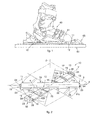
- Fig. 1 shows a form of embodiment in which an adjustment device 10 is provided to adjust the reciprocal position of the footwear 60, in this case a ski boot, with respect to the movement member 62, in this case a ski, only partly shown in fig. 1 .
- the adjustment device 10 comprises a first support member 11, to which the sports footwear 60 is associated, a second support member 12, to which the movement member 62 is associated, and positioning members 13 configured to determine the reciprocal positioning of the first support member 11 and the second support member 12.
- the sports footwear 60 is made in a single body with the first support member 11 or, in other forms of embodiment, it is a separate element, connectable to the first support member 11 by means of connections such as mechanical members, gluing or suchlike.
- the second support member 12 can also be made, in some forms of embodiment, in a single body with the movement member 62, or it can be a separate element or separable from it and subsequently connected to it.
- the first support member 11 and the second support member 12 both have, or at least one of them has, a plate conformation.
- the plate conformation of the first 11 and/or second support member 12 allows to keep a low center of gravity of the group comprising the sports footwear 60, the movement member 62 and the adjustment device 10.
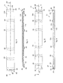
- the first support member 11 and/or the second support member 12 can have a shape that is substantially rectangular ( fig. 2 ), trapezoid, polygonal or a combination thereof, for example as shown in figs. 9 , 10 or 11 .
- first support member 11 and/or the second support member 12 can have end edges 24 with a curvilinear profile.
- the first support member 11 ( figs. 2 and 3 ) can have an oblong development along a first axis X.
- the first support member 11 is provided with a first upper surface 11a in contact or integrated during use with a lower surface 61 of the sports footwear 60, and with a first lower surface 11b associated with the second support member 12.
- the second support member 12 ( figs. 2 , 5 and 6 ) can have an oblong development along a second axis Y.
- the second support member 12 is provided with a second upper surface 12a, able to cooperate with the first support member 11, and with a second lower surface 12b able to interface with the movement member 62.
- Some embodiments of the present invention can provide that the first lower surface 11 b of the first support member 11 is disposed resting against the second upper surface 12a of the second support member 12, to define together a sliding plane ⁇ of the first support member 11 on the second support member 12.
- the positioning members 13 are configured to adjust the position of the first support member 11 and of the second support member 12 allowing them to rotate around an axis of rotation Z.
- the positioning members 13 can comprise pivoting elements 14 able to allow the reciprocal rotation of the first support member 11 and of the second support member 12 around the axis of rotation X.
- pivoting members 14 prevents the reciprocal translation movement of the first support member 11 and of the second support member 12, in directions parallel to the rotation plane ⁇ .
- the pivoting elements 14 comprise a first hole 18, made in the first support member 11, a second hole 19 made in the second support member 12 and a pin 17 inserted in the first hole 18 and in the second hole 19.
- the pin 17, at least for one of its portions, has a cylindrical shape, to allow said rotation and, by way of example, it can be wholly with a circular section or partly with a circular section and partly with a polygonal section.
- the first hole 18 and the second hole 19 have a cross section shape substantially mating with the pin portion 17 that they must accommodate.
- Some implementations of the present invention can provide that the pin 17 is located retracted inside the first hole 18 and the second hole 19, and does not protrude from the thickness of the first support member 11 and the second support member 12.
- the first hole 18 and the second hole 19 are provided through.
- first hole 18 and the second hole 19, or at least one of them can be provided blind toward the first upper surface 11a and/or respectively the second lower surface 12b.
- the pin 17 can be made directly in a single body in the first support member 11, or in the second support member 12 respectively protruding from the first lower surface 11b or from the second upper surface 12a. In this form of embodiment only the second hole 19 or the first hole 18 will be provided.
- the positioning members 13 comprise guide elements 15 configured to guide the reciprocal rotation of the first support member 11 and of the second support member 12 around the axis of rotation Z.
- the guide elements 15 can comprise protruding guides 22 and corresponding guide seatings 23, in which, during use, the protruding guides 22 are inserted sliding.
- protruding guides 22 are ribs, guide blocks, guide wedges, or guide cylinders.
- the protruding guides 22 can be made only on one of either the first lower surface 11b of the first support member 11 or the second upper surface 12a of the second support member 12, or on both.
- the guide seatings 23 can be made on one of either the second upper surface 12a of the second support member 12 or the first lower surface 11b of the first support member 11, or on both
- Possible implementations of the present invention can provide that the protruding guides 22 and the guide seatings 23, or at least one of either the protruding guides 22 or the guide seatings 23, have a conformation, or define a configuration, like the arc of a circle, with a center passing through the axis of rotation Z.
- This configuration allows the guided rotation of the first support member 11 and of the second support member 12 around the axis of rotation Z, by means of sliding of the protruding guides 22 in the guide seatings 23.
- the guide elements 15 are provided in correspondence with at least one of the end edges 24 of the adjustment device 10.
- the guide elements 15 comprise a housing portion 26 provided on one of the end edges 24 of the first support member 11 and the second support member 12, which is provided to house inside it the end edge 24 of the second support member 12 or respectively the first support member 11.
- the end edge 24 can be provided, or not, with a stiffening portion 25 of a shape mating to that of the housing portion 26 and, during use, disposed sliding inside the latter.
- the housing portion 26 and the stiffening portion 25, if present, can have a configuration like the arc of a circle with the center located on the axis of rotation Z. In this way it is possible to guide the rotation of the first support member 11 with respect to the second support member 12.
- the guide elements 15 can comprise at least a through seating 28 in which a corresponding guide pin 29 can be inserted in a sliding manner.
- the through seating 28 can be made on the first support member 11 while the guide pin 29 is associated to the second support member 12 even if their dual disposition is not excluded.
- the through aperture 28 typically has a development like the arc of a circle with the center disposed in correspondence to the axis of rotation Z.
- the guide pin 29 can be made as a single body or be a separate element and subsequently attached to the first support member 11 or to the second support member 12.
- the positioning members 13 comprise constraint elements 16 configured to constrain the reciprocal position of the first support member 11 and of the second support member 12 in a direction parallel to the axis of rotation Z.
- the constraint elements 16 are suitable to keep in reciprocal contact with respect to each other the first upper surface 11 a and the second lower surface 12b respectively of the first support member 11 and the second support member 12.
- Some forms of embodiment can provide that the constraint elements 16 are associated, or integrated with the guide elements 15.
- the constraint elements 16 are made integrated in the protruding guides 22 and the guide seatings 23.
- the protruding guides 22 and the guide seatings 23 can be configured so as to define respective mating portions, shaped as an undercut.
- the protruding guides 22 and the guide seatings 23 can be trapezoidal, "T” or “L” shaped or similar shapes suitable to define an undercut.
- housing portions 26 and/or the stiffening portions 25 also define undercut shaped portions to constrain the reciprocal position of the first support member 11 and the second support member 12.
- constraint elements 16 can be integrated in the pivoting elements 14.
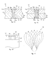
- the pin 17 has two ends 17a flared toward the outside of the adjustment device 10 which engage with respective flared portions 18a and 19a provided in the first hole 18 and in the second hole 19 made respectively in the first support member 11 and the second support member 12.
- the flared ends 17a and the flared portions 18a and 19a can have any shape whatsoever, for example, truncated cone shaped ( fig. 14 ) and cylindrical shape ( fig. 15 ).
- the positioning members 13 are associated to selective adjustment elements 32 ( figs. 7, 8, 9 , 10, 11 ) directly accessible to a user and configured to allow the user to set and adjust the reciprocal angular position of the first support member 11 and of the second support member 12.
- the selective adjustment elements 32 allow to set the reciprocal angulation between the first axis X and the second axis Y of the first support member 11 and respectively of the second support member 12.
- the angulation between the first axis X and the second axis Y is defined by the angle ⁇ and defines the so-called convergence between the sports footwear 60 and the movement member 62.
- the angle ⁇ defines the so-called convergence between the sports footwear 60 and the movement member 62.
- positive and negative conditions of convergence and divergence are shown, of the first support member 11 with respect to the second support member 12.
- the selective adjustment elements 32 can comprise snap-in elements, constraint pegs, interference elements between the support members 11 and 12, rack elements, threaded elements, cam elements, and possible combinations thereof.
- a form of embodiment is visible of an adjustment device 10 that provides selective adjustment elements 32 ( figs. 7-11 ) comprising a first worm screw 33 and a rack 34 attached to the first support member 11 and respectively to the second support member 12, or vice versa.
- the first worm screw 33 is mounted at one end of the second support member 12, it lies on the plane defined by the latter, and is located substantially orthogonal to the second axis Y.
- the rack 34 is provided on one of the end edges 24 of the first support member 11 and so as to cooperate with the first worm screw 33.
- the rack 34 develops like the arc of a circle with its center in correspondence to the axis of rotation Z. Making the first worm screw 33 rotate determines the translation of the rack 34, which in its turn obtains the rotatory movement of the first support member 11 with respect to the second support member 12.
- the first worm screw 33 can be associated to an actuation member 39 suitable to make it rotate.
- the actuation member 39 comprises a toothed wheel 40 mounted at one end of the first worm screw 33 and on which, in its turn, a second worm screw 42 engages.
- the second worm screw 42 is disposed substantially orthogonal to the axis of development of the first worm screw 33 and is provided with a gripping portion directly accessible to a user to allow the adjustment of the adjustment device 10.
- the user determines the simultaneous rotation of the toothed wheel 40.
- the rotation of the toothed wheel 40 determines, in its turn, the rotation of the first worm screw 33 solidly associated thereto.
- Making the first worm screw 33 rotate determines the movement of the rack 34 and therefore the simultaneous variation of the angle ⁇ .
- the adjustment of the angulation can be carried out by a user without needing to disconnect the sports footwear 60 and/or the movement member 62 from the adjustment device 10, but simply acting on the actuation member 39.
- the selective adjustment elements 32 are associated to the guide pin 29 of the guide elements 15 and are provided to determine a condition of interference between the first support member 11 and the second support member 12 so as to constrain their reciprocal position.
- the selective adjustment elements 32 comprise a threaded handle 29a configured to be screwed on a threading made on the guide pin 29.
- the selective adjustment elements 32 comprise a cam 45 that can be selectively actuated by an actuation element 46.
- the cam 45 and the actuation element 46 are mounted respectively on the second support member 12 and on the first support member 11, or vice versa.
- the cam 45 has a substantially circular shape and is pivoted around a pin 47 attached to the second support member 12.
- the pin 47 is disposed substantially orthogonal to the second upper surface 12a and pivots the cam 45 in an eccentric condition with respect to its center.
- the cam 45 is mounted on the second lower surface 12b of the second support member 12.
- the first support member 11 is provided with a through aperture 50 in which the cam 45 is inserted during use.
- the actuation element 46 is attached to the first support member 11 in the through aperture 50 and is disposed so as to cooperate with the cam 45.
- the actuation element 46 can comprise a worm screw 51 suitable to cooperate with a toothing made on the external surface of the cam 45.
- An actuation portion 52 directly accessible by a user can be associated to the worm screw 51 and its actuation provides the rotation of the worm screw 51.
- the rotation of the worm screw 51 determines a simultaneous rotation of the cam 45 and the consequent variation of the angle ⁇ between the first axis X and the second axis Y.
- Indicators 44 ( figs. 2 , 5 , 16 ) provided to allow the user an evaluation of the angle ⁇ between the first axis X and the second axis Y can be associated to the selective adjustment elements 32.
- the indicators 44 can comprise a graduated scale, in association with numerical indicators, provided for example on one of the end edges 24 ( fig. 16 ) of the adjustment device 10.
- the adjustment set by the indicators 44 can be governed by a convergence table 70, an example of which is shown in fig. 17 , which allows a generic user to evaluate the most suitable convergence, before using the sports footwear 60 and/or the movement member 62 associated to the adjustment device 10.
- the convergence table 70 can be configured for specific equipment, for example, providing dedicated convergence tables 70 for each type of ski.
- the sports footwear 60 is associated to the first support member 11 by means of bindings 65 of the known type which can be attached to the sports footwear 60 to allow the simple and quick connection/disconnection of the adjustment device 10 to/from the sports footwear 60.
Abstract
Description
- The present invention concerns an adjustment device for sports footwear to which a movement member can be associated, such as a ski, a skate, a water ski or similar sports equipment.
- In particular, the adjustment device according to the present invention allows to adjust the reciprocal position of the movement member with respect to sports footwear into which the user's foot is inserted.
- A possible and non-exclusive application of the adjustment device is for use by the disabled.
- Sports are known, such as skiing, skating, water skiing or similar sports, in which sports footwear is used, such as boots or shoes, which are worn by a user and to which movement members are associated, such as skis or skates.
- The movement members are guided during use by the action of the feet and legs of the person wearing them.
- It is therefore fundamental to facilitate the coordinated action of the feet and legs to improve the pace and performance of the movement members, particularly during competitive sporting activity.
- Merely by way of example, each model of ski has its own radius of curvature and different technical characteristics, which must be coordinated by the user during movement.
- When skiing downhill, a skier may have skis that bend over their whole length in proportion to the skier's weight and the speed.
- The natural tendency of the skis to converge on their tips during descent obliges the skier to sustain vibrations which not only slow down the run but also oblige him/her to force and correct the curved line imparted to the ski.
- On the contrary, if the skis had too open a convergence, this would cause a reciprocal distancing that would promote a loss of adherence and thrust. For this reason some known solutions provide to make the ski converge, during use, in correspondence with the tips, but this has the disadvantage of vibrations and excessive weight load.
- In such sports techniques are also used which facilitate the user's movement by bringing together or separating the ends of the movement members.
- For example, when skiing, the tips of the skis can be brought together during curving in order to increase the grip on the snow, or vice versa they can be distanced if the skier wants to go up a slope.
- These settings of the movement members are set by the particular posture of the user's legs and feet, which can be different according to the conformation of the human body.
- To solve these problems, adjustment devices are also known, associated with the movement members and the footwear, which allow to adjust the angle, also called convergence, of the axes of the feet with respect to the axis of the movement member.
- The purpose of the adjustment is to adapt the setting of the movement member with respect to the footwear, to adapt it both to the posture/setting of the user and also to particular positions that must be assumed depending on a specific pace or conformation of the plane on which the movement members move.
- Footwear is also known, for example ski boots, provided with interchangeable attachment ends to which the bindings of the skis are connected. The attachment ends can be replaced to personalize the convergence of the skis in a predetermined manner. This solution does not allow to adapt the convergence configuration quickly, since it is necessary to replace at least the attachment ends.
- Adjustment devices are also known, associated for example to skates, to adjust the convergence between the boot and the movement members, such as rollers or a blade. In order to make the adjustment, it is necessary to intervene with suitable tools on the boot and on the movement members, in order to modify their reciprocal position on each occasion. These adjustment operations also require that at least part of the skates is dismantled, in order to make the desired modifications for convergence.
- Documents
US-A-5,452,907 ,EP-A-0.761.261 ,EP-A-1.316.265 ,US-A-5,293,702 andDE-A-102009010801 describe adjustment devices of a known type. - There is therefore a need to perfect an adjustment device for sports footwear that can overcome at least one of the disadvantages of the state of the art.
- In particular, one purpose of the present invention is to obtain an adjustment device for sports footwear that is simple to use and that allows to vary the setting of the footwear with respect to a movement member, without needing to detach the sports footwear from the movement members.
- Another purpose of the present invention is to obtain an adjustment device for sports footwear that allows to perform the adjustment operations directly during normal use of the movement member, for example to adapt it to specific paces or characteristics of the ground.
- Another purpose of the present invention is to obtain an adjustment device for sports footwear that does not require the user to remove the footwear from the foot in order to make the adjustment.
- The Applicant has devised, tested and embodied the present invention to overcome the shortcomings of the state of the art and to obtain these and other purposes and advantages.
- The present invention is set forth and characterized in the independent claims, while the dependent claims describe other characteristics of the invention or variants to the main inventive idea.
- In accordance with the above purposes, an adjustment device for sports footwear is configured to adjust the position of a movement member such as a ski, a skate, a group of wheels, a blade with respect to the sports footwear.
- According to one feature of the present invention, the adjustment device comprises a first support member associable to the sports footwear, a second support member associable to the movement member, and positioning members configured to allow the reciprocal positioning of the first support member and the second support member, by means of their rotation around a common axis of rotation.
- In this way a user can modify as desired the convergence/divergence setting between the sports footwear worn and the movement member, for example to adapt it to his/her own specific requirements or to adapt it to work conditions or conditions of the ground on which it is moving. The present invention therefore simplifies the use of the movement members and also simplifies, for example, learning how to use them.
- According to one feature of the present invention, the positioning members comprise guide elements associated with the first support member and second support member around the axis of rotation: the guide elements comprise, in the first support member and the second support member, protruding guides and corresponding guide seatings in which said protruding guides are inserted, sliding during use.
- Forms of embodiment described here also concern a kit for practicing sporting activity, comprising at least a movement member provided with at least a binding to attach the sports footwear, and an adjustment device according to the present description, provided to adjust the position of the movement member with respect to the sports footwear.
- The present invention also concerns a method to adjust the position of a movement member such as a ski, a skate, a group of wheels, a blade, with respect to the sports footwear. According to one feature of the method, it provides to position reciprocally a first support member with respect to a second support member by means of rotation around an axis of rotation using guide elements, associated with the first support member and the second support member around the axis of rotation, and which comprise, in the first support member and the second support member, protruding guides and corresponding guide seatings in which said protruding guides are inserted, sliding during use. The sports footwear is associated with the first support member and the movement member is associated with the second support member for reciprocal adjustment.
- These and other aspects, characteristics and advantages of the present disclosure will be better understood with reference to the following description, drawings and attached claims. The drawings, which are integrated and form part of the present description, show some forms of embodiment of the present invention, and together with the description, are intended to describe the principles of the disclosure.
- The various aspects and characteristics described in the present description can be applied individually where possible. These individual aspects, for example aspects and characteristics described in the attached dependent claims, can be the object of divisional applications.
- It is understood that any aspect or characteristic that is discovered, during the patenting process, to be already known, shall not be claimed and shall be the object of a disclaimer.
- These and other characteristics of the present invention will become apparent from the following description of a preferential form of embodiment, given as a non-restrictive example with reference to the attached drawings wherein:
-
fig. 1 is a lateral view of an adjustment device, attached to a sports footwear and to a movement member, according to a form of embodiment of the present invention; -
fig. 2 is a schematic perspective view of an adjustment device for a sports footwear according to one form of embodiment of the present invention; -
fig. 3 is a view from above of a first component of the adjustment device infig. 1 ; -
fig. 4 is a section view from IV to IV infig. 3 of the first component; -
fig. 5 is a view from above of a second component of the adjustment device infig. 1 ; -
fig. 6 is a section view from VI to VI infig. 5 of the second component; -
fig. 7 is a section view of the first component infig. 4 and of the second component infig. 6 in their assembled condition; -
fig. 8 is another section view from VIII to VIII infig. 7 ; -
fig. 9 is a perspective view of another form of embodiment of the adjustment device for a sports footwear according to the present invention; -
fig. 10 is a perspective view of another form of embodiment of an adjustment device for a sports footwear according to the present invention; -
fig. 11 is a perspective view of yet another form of embodiment of an adjustment device for a sports footwear according to the present invention; -
fig. 12 is a view from above offig. 1 in a first adjustment condition; -
fig. 13 is a view from above offig. 1 in a second adjustment condition; -
fig. 14 shows an enlarged detail of an adjustment device in accordance with one form of embodiment of the present invention; -
fig. 15 is a variant offig. 14 ; -
fig. 16 shows an enlarged detail offig. 2 ; -
fig. 17 is a schematic representation of a possible adjustment obtained with the adjustment device according to the present invention. - To facilitate comprehension, the same reference numbers have been used, where possible, to identify identical common elements in the drawings. It is understood that elements and characteristics of one form of embodiment can conveniently be incorporated into other forms of embodiment without further clarifications.
- We shall now refer in detail to the various forms of embodiment of the present invention, of which one or more examples are shown in the attached drawing. Each example is supplied by way of illustration of the invention and shall not be understood as a limitation thereof. For example, the characteristics shown or described insomuch as they are part of one form of embodiment can be adopted on, or in association with, other forms of embodiment to produce another form of embodiment. It is understood that the present invention shall include all such modifications and variants.
- With reference to the attached drawings, we shall now describe an
adjustment device 10 forsports footwear 60 configured to adjust the position of amovement member 62 with respect to thesports footwear 60. - Forms of embodiment of the present invention can provide that the
sports footwear 60 is chosen from a group comprising a ski boot, a skating shoe or similar footwear. - Other forms of embodiment, which can possibly be combined with the forms of embodiment described here, provide that the
movement member 62 is a ski, a skate, an inline skate, a water ski, a group of wheels, a blade for ice skating or similar sliding elements. -
Fig. 1 shows a form of embodiment in which anadjustment device 10 is provided to adjust the reciprocal position of thefootwear 60, in this case a ski boot, with respect to themovement member 62, in this case a ski, only partly shown infig. 1 . - The form of embodiment shown in
figs. 1 and 2 provides that theadjustment device 10 comprises afirst support member 11, to which thesports footwear 60 is associated, asecond support member 12, to which themovement member 62 is associated, andpositioning members 13 configured to determine the reciprocal positioning of thefirst support member 11 and thesecond support member 12. - Some forms of embodiment can provide that the
sports footwear 60 is made in a single body with thefirst support member 11 or, in other forms of embodiment, it is a separate element, connectable to thefirst support member 11 by means of connections such as mechanical members, gluing or suchlike. In the same way, thesecond support member 12 can also be made, in some forms of embodiment, in a single body with themovement member 62, or it can be a separate element or separable from it and subsequently connected to it. - In possible forms of embodiment of the present invention, for example shown in
figs. 1 - 11 , thefirst support member 11 and thesecond support member 12 both have, or at least one of them has, a plate conformation. - The plate conformation of the first 11 and/or
second support member 12 allows to keep a low center of gravity of the group comprising thesports footwear 60, themovement member 62 and theadjustment device 10. - The
first support member 11 and/or thesecond support member 12 can have a shape that is substantially rectangular (fig. 2 ), trapezoid, polygonal or a combination thereof, for example as shown infigs. 9 ,10 or 11 . - In possible implementations of the present invention, the
first support member 11 and/or thesecond support member 12 can haveend edges 24 with a curvilinear profile. - The first support member 11 (
figs. 2 and3 ) can have an oblong development along a first axis X. - The
first support member 11 is provided with a firstupper surface 11a in contact or integrated during use with alower surface 61 of thesports footwear 60, and with a firstlower surface 11b associated with thesecond support member 12. - The second support member 12 (
figs. 2 ,5 and 6 ) can have an oblong development along a second axis Y. - The
second support member 12 is provided with a secondupper surface 12a, able to cooperate with thefirst support member 11, and with a secondlower surface 12b able to interface with themovement member 62. - Some embodiments of the present invention can provide that the first
lower surface 11 b of thefirst support member 11 is disposed resting against the secondupper surface 12a of thesecond support member 12, to define together a sliding plane β of thefirst support member 11 on thesecond support member 12. - The
positioning members 13 are configured to adjust the position of thefirst support member 11 and of thesecond support member 12 allowing them to rotate around an axis of rotation Z. - According to some forms of embodiment, shown for example in
figs. 9-11 thepositioning members 13 can comprise pivotingelements 14 able to allow the reciprocal rotation of thefirst support member 11 and of thesecond support member 12 around the axis of rotation X. - The action of the pivoting
members 14 prevents the reciprocal translation movement of thefirst support member 11 and of thesecond support member 12, in directions parallel to the rotation plane β. - With reference to the forms of embodiment shown in
figs. 9 ,10 ,11 ,14 and 15 , the pivotingelements 14 comprise afirst hole 18, made in thefirst support member 11, asecond hole 19 made in thesecond support member 12 and apin 17 inserted in thefirst hole 18 and in thesecond hole 19. - The
pin 17, at least for one of its portions, has a cylindrical shape, to allow said rotation and, by way of example, it can be wholly with a circular section or partly with a circular section and partly with a polygonal section. Similarly, thefirst hole 18 and thesecond hole 19 have a cross section shape substantially mating with thepin portion 17 that they must accommodate. - Some implementations of the present invention can provide that the
pin 17 is located retracted inside thefirst hole 18 and thesecond hole 19, and does not protrude from the thickness of thefirst support member 11 and thesecond support member 12. - In the forms of embodiment in
figs. 9 ,10 ,11 ,14 and 15 , thefirst hole 18 and thesecond hole 19 are provided through. - According to variant forms of embodiment the
first hole 18 and thesecond hole 19, or at least one of them, can be provided blind toward the firstupper surface 11a and/or respectively the secondlower surface 12b. - According to variant forms of embodiment, not shown in the drawings, the
pin 17 can be made directly in a single body in thefirst support member 11, or in thesecond support member 12 respectively protruding from the firstlower surface 11b or from the secondupper surface 12a. In this form of embodiment only thesecond hole 19 or thefirst hole 18 will be provided. - Further forms of embodiment, possibly combinable with the forms of embodiment described here, provide that the
positioning members 13 compriseguide elements 15 configured to guide the reciprocal rotation of thefirst support member 11 and of thesecond support member 12 around the axis of rotation Z. - With reference to forms of embodiment described using
figs. 2-11 , theguide elements 15 can comprise protruding guides 22 and corresponding guide seatings 23, in which, during use, the protruding guides 22 are inserted sliding. Possible examples of protruding guides 22 are ribs, guide blocks, guide wedges, or guide cylinders. - The protruding guides 22 can be made only on one of either the first
lower surface 11b of thefirst support member 11 or the secondupper surface 12a of thesecond support member 12, or on both. Similarly the guide seatings 23 can be made on one of either the secondupper surface 12a of thesecond support member 12 or the firstlower surface 11b of thefirst support member 11, or on both - Possible implementations of the present invention can provide that the protruding guides 22 and the guide seatings 23, or at least one of either the protruding guides 22 or the guide seatings 23, have a conformation, or define a configuration, like the arc of a circle, with a center passing through the axis of rotation Z. This configuration allows the guided rotation of the
first support member 11 and of thesecond support member 12 around the axis of rotation Z, by means of sliding of the protruding guides 22 in the guide seatings 23. - In accordance with forms of embodiment of the present invention, for example shown in
figs. 2 to 9 , theguide elements 15 are provided in correspondence with at least one of the end edges 24 of theadjustment device 10. - In accordance with forms of embodiment shown in
figs. 2-9 theguide elements 15 comprise ahousing portion 26 provided on one of the end edges 24 of thefirst support member 11 and thesecond support member 12, which is provided to house inside it theend edge 24 of thesecond support member 12 or respectively thefirst support member 11. - The
end edge 24 can be provided, or not, with a stiffeningportion 25 of a shape mating to that of thehousing portion 26 and, during use, disposed sliding inside the latter. - The
housing portion 26 and the stiffeningportion 25, if present, can have a configuration like the arc of a circle with the center located on the axis of rotation Z. In this way it is possible to guide the rotation of thefirst support member 11 with respect to thesecond support member 12. - In accordance with another form of embodiment, possibly combinable with the forms of embodiment described here and shown by way of example in
fig. 10 , theguide elements 15 can comprise at least a throughseating 28 in which acorresponding guide pin 29 can be inserted in a sliding manner. The throughseating 28 can be made on thefirst support member 11 while theguide pin 29 is associated to thesecond support member 12 even if their dual disposition is not excluded. - The through
aperture 28 typically has a development like the arc of a circle with the center disposed in correspondence to the axis of rotation Z. - The
guide pin 29 can be made as a single body or be a separate element and subsequently attached to thefirst support member 11 or to thesecond support member 12. - Some implementations of the present invention provide that the
positioning members 13 compriseconstraint elements 16 configured to constrain the reciprocal position of thefirst support member 11 and of thesecond support member 12 in a direction parallel to the axis of rotation Z. Some implementations provide that theconstraint elements 16 are suitable to keep in reciprocal contact with respect to each other the firstupper surface 11 a and the secondlower surface 12b respectively of thefirst support member 11 and thesecond support member 12. - Some forms of embodiment can provide that the
constraint elements 16 are associated, or integrated with theguide elements 15. - Some implementations, shown for example in
figs. 2-9 , provide that theconstraint elements 16 are made integrated in the protruding guides 22 and the guide seatings 23. By way of example, the protruding guides 22 and the guide seatings 23 can be configured so as to define respective mating portions, shaped as an undercut. - Merely by way of example, the protruding guides 22 and the guide seatings 23 can be trapezoidal, "T" or "L" shaped or similar shapes suitable to define an undercut.
- Further forms of embodiment also provide that the
housing portions 26 and/or thestiffening portions 25 also define undercut shaped portions to constrain the reciprocal position of thefirst support member 11 and thesecond support member 12. - In other forms of embodiment the
constraint elements 16 can be integrated in the pivotingelements 14. - For example, with reference to
fig. 14 , thepin 17 has twoends 17a flared toward the outside of theadjustment device 10 which engage with respective flaredportions first hole 18 and in thesecond hole 19 made respectively in thefirst support member 11 and thesecond support member 12. - The flared ends 17a and the flared
portions fig. 14 ) and cylindrical shape (fig. 15 ). - The
positioning members 13 are associated to selective adjustment elements 32 (figs. 7, 8, 9 ,10, 11 ) directly accessible to a user and configured to allow the user to set and adjust the reciprocal angular position of thefirst support member 11 and of thesecond support member 12. - In particular, the
selective adjustment elements 32 allow to set the reciprocal angulation between the first axis X and the second axis Y of thefirst support member 11 and respectively of thesecond support member 12. - The angulation between the first axis X and the second axis Y is defined by the angle α and defines the so-called convergence between the
sports footwear 60 and themovement member 62. With reference tofigs. 12 and 13 positive and negative conditions of convergence and divergence are shown, of thefirst support member 11 with respect to thesecond support member 12. - The
selective adjustment elements 32 can comprise snap-in elements, constraint pegs, interference elements between thesupport members - In
figs. 7 and 8 a form of embodiment is visible of anadjustment device 10 that provides selective adjustment elements 32 (figs. 7-11 ) comprising afirst worm screw 33 and arack 34 attached to thefirst support member 11 and respectively to thesecond support member 12, or vice versa. - With reference to
figs. 7 and 8 , thefirst worm screw 33 is mounted at one end of thesecond support member 12, it lies on the plane defined by the latter, and is located substantially orthogonal to the second axis Y. - The
rack 34 is provided on one of the end edges 24 of thefirst support member 11 and so as to cooperate with thefirst worm screw 33. - The
rack 34 develops like the arc of a circle with its center in correspondence to the axis of rotation Z. Making thefirst worm screw 33 rotate determines the translation of therack 34, which in its turn obtains the rotatory movement of thefirst support member 11 with respect to thesecond support member 12. - The
first worm screw 33 can be associated to anactuation member 39 suitable to make it rotate. Theactuation member 39 comprises atoothed wheel 40 mounted at one end of thefirst worm screw 33 and on which, in its turn, asecond worm screw 42 engages. - The
second worm screw 42 is disposed substantially orthogonal to the axis of development of thefirst worm screw 33 and is provided with a gripping portion directly accessible to a user to allow the adjustment of theadjustment device 10. In particular, by making thesecond worm screw 42 rotate, the user determines the simultaneous rotation of thetoothed wheel 40. The rotation of thetoothed wheel 40 determines, in its turn, the rotation of thefirst worm screw 33 solidly associated thereto. Making thefirst worm screw 33 rotate determines the movement of therack 34 and therefore the simultaneous variation of the angle α. - The adjustment of the angulation can be carried out by a user without needing to disconnect the
sports footwear 60 and/or themovement member 62 from theadjustment device 10, but simply acting on theactuation member 39. - According to variant forms of embodiment, like the one shown in
fig. 10 , theselective adjustment elements 32 are associated to theguide pin 29 of theguide elements 15 and are provided to determine a condition of interference between thefirst support member 11 and thesecond support member 12 so as to constrain their reciprocal position. - In particular, with reference to
fig. 10 , theselective adjustment elements 32 comprise a threadedhandle 29a configured to be screwed on a threading made on theguide pin 29. - Screwing the threaded
handle 29a onto theguide pin 29, the former exerts a condition of compression between the firstlower surface 11b and the secondupper surface 12a respectively of thefirst support member 11 and thesecond support member 12, in practice constraining the position of the latter two. - According to another variant form of embodiment shown in
fig. 11 , theselective adjustment elements 32 comprise acam 45 that can be selectively actuated by anactuation element 46. - The
cam 45 and theactuation element 46 are mounted respectively on thesecond support member 12 and on thefirst support member 11, or vice versa. - The
cam 45 has a substantially circular shape and is pivoted around apin 47 attached to thesecond support member 12. Thepin 47 is disposed substantially orthogonal to the secondupper surface 12a and pivots thecam 45 in an eccentric condition with respect to its center. In the case shown infig. 11 , thecam 45 is mounted on the secondlower surface 12b of thesecond support member 12. Thefirst support member 11 is provided with a throughaperture 50 in which thecam 45 is inserted during use. - The
actuation element 46 is attached to thefirst support member 11 in the throughaperture 50 and is disposed so as to cooperate with thecam 45. - The
actuation element 46 can comprise a worm screw 51 suitable to cooperate with a toothing made on the external surface of thecam 45. - An
actuation portion 52, directly accessible by a user can be associated to the worm screw 51 and its actuation provides the rotation of the worm screw 51. The rotation of the worm screw 51 determines a simultaneous rotation of thecam 45 and the consequent variation of the angle α between the first axis X and the second axis Y. - Indicators 44 (
figs. 2 ,5 ,16 ) provided to allow the user an evaluation of the angle α between the first axis X and the second axis Y can be associated to theselective adjustment elements 32. - The
indicators 44 can comprise a graduated scale, in association with numerical indicators, provided for example on one of the end edges 24 (fig. 16 ) of theadjustment device 10. - The adjustment set by the
indicators 44 can be governed by a convergence table 70, an example of which is shown infig. 17 , which allows a generic user to evaluate the most suitable convergence, before using thesports footwear 60 and/or themovement member 62 associated to theadjustment device 10. - The convergence table 70 can be configured for specific equipment, for example, providing dedicated convergence tables 70 for each type of ski.
- In the form of embodiment shown in
fig. 1 , thesports footwear 60 is associated to thefirst support member 11 by means ofbindings 65 of the known type which can be attached to thesports footwear 60 to allow the simple and quick connection/disconnection of theadjustment device 10 to/from thesports footwear 60. - It is clear that modifications and/or additions of parts may be made to the adjustment device for a sports footwear as described heretofore, without departing from the field and scope of the present invention.
- It is also clear that, although the present invention has been described with reference to some specific examples, a person of skill in the art shall certainly be able to achieve many other equivalent forms of adjustment device for a sports footwear, having the characteristics as set forth in the claims and hence all coming within the field of protection defined thereby.
Claims (14)
- Adjustment device for a sports footwear (60) configured to adjust the position of a movement member (62) such as a ski, a skate, a group of wheels, a blade, with respect to said sports footwear (60), characterized in that it comprises a first support member (11), associable to said sports footwear (60), a second support member (12), associable to said movement member (62), and positioning members (13) configured to allow the reciprocal positioning of said first support member (11) and said second support member (12) by means of their rotation around a common axis of rotation (Z), wherein said positioning members (13) comprise guide elements (15) associated to said first support member (11) and said second support member (12) around said axis of rotation (Z), which guide elements (15) comprise, in said first support member (11) and said second support member (12), protruding guides (22) and corresponding guide seatings (23) into which, during use, said protruding guides (22) are inserted sliding.
- Device as in claim 1, characterized in that at least one of either said first support member (11) or said second support member (12) has a plate configuration.
- Device as in claim 1 or 2, characterized in that said first support member (11) and said second support member (12) have respective surfaces (11b, 12a) of reciprocal contact defining a common sliding plane (ß) for the rotation of said first support member (11) and said second support member (12).
- Support device as in any claim hereinbefore, characterized in that said positioning members (13) comprise pivoting elements (14) associated to said first support member (11) and said second support member (12) to allow their rotation around said axis of rotation (Z).
- Support device as in any claim hereinbefore, characterized in that said guide elements (15) are configured to allow the rotation of said first support member (11) with respect to said second support member (12).
- Support device as in any claim hereinbefore, characterized in that said guide seatings (23) and said protruding guides (22) have a configuration like the arc of a circle with the center passing through said axis of rotation (Z).
- Device as in any claim hereinbefore, characterized in that said guide elements (15) comprise at least a through seating (28) and a guide pin (29), insertable in sliding manner into said through seating (28), provided on said first support member (11) and respectively said second support member (12), or vice versa.
- Device as in any claim hereinbefore, characterized in that said positioning members (13) comprise constraint elements (16) configured to constrain the reciprocal position of the first support member (11) and of the second support member (12) in a direction parallel to said axis of rotation (Z).
- Device as in claim 8, characterized in that said constraint elements (16) are integrated in said protruding guides (22) and said guide seatings (23).
- Device as in any claim hereinbefore, characterized in that said positioning members (13) comprise selective adjustment elements (32) directly accessible by a user and configured to allow the adjustment of the reciprocal angular position of said first support member (11) and said second support member (12).
- Device as in claim 10, characterized in that said selective adjustment elements (32) comprise snap-in elements, constraint pegs, interference elements between the first support element (11) and the second support element (12), rack elements, threaded elements, cam elements, or possible combinations thereof.
- Device as in claim hereinbefore, characterized in that the protruding guides (22) comprises ribs, or guide blocks, or guide wedges, or guide cylinders.
- Kit to practice sports, comprising at least a movement member (62) provided at least with a binding (65) to attach a sports footwear (60) and an adjustment device (10) as in any claim hereinbefore, provided to adjust the position of the movement member (62) with respect to the sports footwear (60).
- Method to adjust the position of a movement member (62) such as a ski, a skate, a group of wheels, a blade, with respect to a sports footwear (60), characterized in that it comprises the reciprocal positioning of a first support member (11) with respect to a second support member (12) by means of rotation around an axis of rotation (Z), using guide elements (15), associated to said first support member (11) and said second support member (12) around said axis of rotation (Z), and which comprise, in said first support member (11) and said second support member (12), protruding guides (22) and corresponding guide seatings (23) into which, during use, said protruding guides (22) are inserted sliding, said sports footwear being associated to said first support member (11) (60) and said movement member (62) being associated to said second support member (12).
Applications Claiming Priority (1)
| Application Number | Priority Date | Filing Date | Title |
|---|---|---|---|
| IT000103A ITUD20130103A1 (en) | 2013-08-06 | 2013-08-06 | ADJUSTMENT DEVICE FOR A SPORTS FOOTWEAR |
Publications (1)
| Publication Number | Publication Date |
|---|---|
| EP2856898A1 true EP2856898A1 (en) | 2015-04-08 |
Family
ID=49486607
Family Applications (1)
| Application Number | Title | Priority Date | Filing Date |
|---|---|---|---|
| EP20140179967 Withdrawn EP2856898A1 (en) | 2013-08-06 | 2014-08-06 | Adjustment device for sports footwear |
Country Status (2)
| Country | Link |
|---|---|
| EP (1) | EP2856898A1 (en) |
| IT (1) | ITUD20130103A1 (en) |
Cited By (2)
| Publication number | Priority date | Publication date | Assignee | Title |
|---|---|---|---|---|
| WO2017131590A1 (en) * | 2016-01-27 | 2017-08-03 | Elan, D,O.O. | Collapsible ski |
| WO2019092513A1 (en) * | 2017-11-08 | 2019-05-16 | Elan, D.O.O. | Folding ski |
Citations (8)
| Publication number | Priority date | Publication date | Assignee | Title |
|---|---|---|---|---|
| US5293702A (en) | 1990-09-07 | 1994-03-15 | Daiwa Seiko | Method and apparatus for selectively orienting ski boot |
| US5452907A (en) | 1993-07-19 | 1995-09-26 | K-2 Corporation | Skate with adjustable base and frame |
| EP0761261A1 (en) | 1995-08-08 | 1997-03-12 | NORDICA S.p.A | Snowboard binding with angular adjustment |
| US6022040A (en) * | 1998-04-23 | 2000-02-08 | Buzbee; Douglas C. | Freely rotating step-in snowboard binding |
| EP1316265A1 (en) | 2001-11-06 | 2003-06-04 | ATOMIC Austria GmbH | Sport shoe, in particular ski shoe |
| US20040207179A1 (en) * | 2003-01-31 | 2004-10-21 | Marc Sacco | Binding adjustment system |
| DE102009010801A1 (en) | 2008-02-29 | 2009-09-03 | Atomic Austria Gmbh | Front jaw for use in safety ski binding for holding front section of boot, has adjusting device formed such that predefined opening- or receiving cavity of holder remains unchanged during user side change of lateral adjustment of holder |
| WO2012103480A1 (en) * | 2011-01-27 | 2012-08-02 | Brendan Walker | Board sport bindings |
Family Cites Families (1)
| Publication number | Priority date | Publication date | Assignee | Title |
|---|---|---|---|---|
| US5906388A (en) * | 1997-01-14 | 1999-05-25 | Quiksilver, Inc. | Footwear mounting system |
-
2013
- 2013-08-06 IT IT000103A patent/ITUD20130103A1/en unknown
-
2014
- 2014-08-06 EP EP20140179967 patent/EP2856898A1/en not_active Withdrawn
Patent Citations (8)
| Publication number | Priority date | Publication date | Assignee | Title |
|---|---|---|---|---|
| US5293702A (en) | 1990-09-07 | 1994-03-15 | Daiwa Seiko | Method and apparatus for selectively orienting ski boot |
| US5452907A (en) | 1993-07-19 | 1995-09-26 | K-2 Corporation | Skate with adjustable base and frame |
| EP0761261A1 (en) | 1995-08-08 | 1997-03-12 | NORDICA S.p.A | Snowboard binding with angular adjustment |
| US6022040A (en) * | 1998-04-23 | 2000-02-08 | Buzbee; Douglas C. | Freely rotating step-in snowboard binding |
| EP1316265A1 (en) | 2001-11-06 | 2003-06-04 | ATOMIC Austria GmbH | Sport shoe, in particular ski shoe |
| US20040207179A1 (en) * | 2003-01-31 | 2004-10-21 | Marc Sacco | Binding adjustment system |
| DE102009010801A1 (en) | 2008-02-29 | 2009-09-03 | Atomic Austria Gmbh | Front jaw for use in safety ski binding for holding front section of boot, has adjusting device formed such that predefined opening- or receiving cavity of holder remains unchanged during user side change of lateral adjustment of holder |
| WO2012103480A1 (en) * | 2011-01-27 | 2012-08-02 | Brendan Walker | Board sport bindings |
Cited By (4)
| Publication number | Priority date | Publication date | Assignee | Title |
|---|---|---|---|---|
| WO2017131590A1 (en) * | 2016-01-27 | 2017-08-03 | Elan, D,O.O. | Collapsible ski |
| US10328330B2 (en) | 2016-01-27 | 2019-06-25 | Elan, D.O.O. | Collapsible ski |
| WO2019092513A1 (en) * | 2017-11-08 | 2019-05-16 | Elan, D.O.O. | Folding ski |
| US11167199B2 (en) | 2017-11-08 | 2021-11-09 | Elan, D.O.O. | Folding ski |
Also Published As
| Publication number | Publication date |
|---|---|
| ITUD20130103A1 (en) | 2015-02-07 |
Similar Documents
| Publication | Publication Date | Title |
|---|---|---|
| US4026045A (en) | Boot sole structures | |
| US9220968B2 (en) | Heel lock for splitboard binding interface | |
| EP2696949B1 (en) | A binding | |
| JPH11502430A (en) | Adjustable foot device | |
| EP0610652A1 (en) | Skate | |
| US20190168101A1 (en) | Ice skate attachment | |
| EP2787851B1 (en) | Ski boot | |
| US9452343B2 (en) | SKI binding with forefoot fixing module | |
| EP2856898A1 (en) | Adjustment device for sports footwear | |
| US9538805B2 (en) | Ski boot and similar sport footwear | |
| US2230553A (en) | Ice skate | |
| US8201836B2 (en) | Toe binding of a safety ski binding | |
| US3243191A (en) | Adjustable ice skate | |
| KR101256365B1 (en) | Detachable whell fixing device | |
| US9320314B2 (en) | Sports footwear provided with an adjustable rear spoiler | |
| US6053522A (en) | Water ski binding systems | |
| WO1991007889A1 (en) | Device for cross-country ski boot | |
| EP2253357B1 (en) | Loop binding with rotating platform | |
| US9339717B2 (en) | Apparatus for altering the ramp angle of a ski binding and method for optimizing the (fore-aft) balance of a skier | |
| EP3799939A1 (en) | Adapter part for a cross country ski binding | |
| EP0756882A1 (en) | Snowboard adjustable binding | |
| EP2666380B1 (en) | Sport footwear such as a ski boot or suchlike | |
| CZ309865B6 (en) | A splitboard binding base with means for fixing it on skis | |
| CA2787386C (en) | An ice skate | |
| CH710578A2 (en) | sports footwear suitable for winter sports. |
Legal Events
| Date | Code | Title | Description |
|---|---|---|---|
| PUAI | Public reference made under article 153(3) epc to a published international application that has entered the european phase |
Free format text: ORIGINAL CODE: 0009012 |
|
| 17P | Request for examination filed |
Effective date: 20140806 |
|
| AK | Designated contracting states |
Kind code of ref document: A1 Designated state(s): AL AT BE BG CH CY CZ DE DK EE ES FI FR GB GR HR HU IE IS IT LI LT LU LV MC MK MT NL NO PL PT RO RS SE SI SK SM TR |
|
| AX | Request for extension of the european patent |
Extension state: BA ME |
|
| R17P | Request for examination filed (corrected) |
Effective date: 20160126 |
|
| RBV | Designated contracting states (corrected) |
Designated state(s): AL AT BE BG CH CY CZ DE DK EE ES FI FR GB GR HR HU IE IS IT LI LT LU LV MC MK MT NL NO PL PT RO RS SE SI SK SM TR |
|
| RIC1 | Information provided on ipc code assigned before grant |
Ipc: A43B 5/04 20060101AFI20170208BHEP Ipc: A43B 5/16 20060101ALI20170208BHEP Ipc: A63C 9/086 20120101ALI20170208BHEP Ipc: A63C 9/00 20120101ALI20170208BHEP Ipc: A63C 1/28 20060101ALI20170208BHEP Ipc: A63C 9/081 20120101ALI20170208BHEP |
|
| GRAP | Despatch of communication of intention to grant a patent |
Free format text: ORIGINAL CODE: EPIDOSNIGR1 |
|
| INTG | Intention to grant announced |
Effective date: 20170327 |
|
| STAA | Information on the status of an ep patent application or granted ep patent |
Free format text: STATUS: THE APPLICATION IS DEEMED TO BE WITHDRAWN |
|
| 18D | Application deemed to be withdrawn |
Effective date: 20170808 |