EP2856029B1 - Control device for gas taps - Google Patents
Control device for gas taps Download PDFInfo
- Publication number
- EP2856029B1 EP2856029B1 EP13735442.9A EP13735442A EP2856029B1 EP 2856029 B1 EP2856029 B1 EP 2856029B1 EP 13735442 A EP13735442 A EP 13735442A EP 2856029 B1 EP2856029 B1 EP 2856029B1
- Authority
- EP
- European Patent Office
- Prior art keywords
- tap
- control means
- manual
- transmission member
- gas
- Prior art date
- Legal status (The legal status is an assumption and is not a legal conclusion. Google has not performed a legal analysis and makes no representation as to the accuracy of the status listed.)
- Active
Links
Images






Classifications
-
- F—MECHANICAL ENGINEERING; LIGHTING; HEATING; WEAPONS; BLASTING
- F24—HEATING; RANGES; VENTILATING
- F24C—DOMESTIC STOVES OR RANGES ; DETAILS OF DOMESTIC STOVES OR RANGES, OF GENERAL APPLICATION
- F24C3/00—Stoves or ranges for gaseous fuels
- F24C3/12—Arrangement or mounting of control or safety devices
- F24C3/126—Arrangement or mounting of control or safety devices on ranges
-
- F—MECHANICAL ENGINEERING; LIGHTING; HEATING; WEAPONS; BLASTING
- F23—COMBUSTION APPARATUS; COMBUSTION PROCESSES
- F23N—REGULATING OR CONTROLLING COMBUSTION
- F23N1/00—Regulating fuel supply
- F23N1/007—Regulating fuel supply using mechanical means
-
- F—MECHANICAL ENGINEERING; LIGHTING; HEATING; WEAPONS; BLASTING
- F23—COMBUSTION APPARATUS; COMBUSTION PROCESSES
- F23N—REGULATING OR CONTROLLING COMBUSTION
- F23N5/00—Systems for controlling combustion
- F23N5/02—Systems for controlling combustion using devices responsive to thermal changes or to thermal expansion of a medium
- F23N5/10—Systems for controlling combustion using devices responsive to thermal changes or to thermal expansion of a medium using thermocouples
- F23N5/107—Systems for controlling combustion using devices responsive to thermal changes or to thermal expansion of a medium using thermocouples using mechanical means, e.g. safety valves
-
- F—MECHANICAL ENGINEERING; LIGHTING; HEATING; WEAPONS; BLASTING
- F23—COMBUSTION APPARATUS; COMBUSTION PROCESSES
- F23N—REGULATING OR CONTROLLING COMBUSTION
- F23N5/00—Systems for controlling combustion
- F23N5/20—Systems for controlling combustion with a time program acting through electrical means, e.g. using time-delay relays
- F23N5/203—Systems for controlling combustion with a time program acting through electrical means, e.g. using time-delay relays using electronic means
-
- F—MECHANICAL ENGINEERING; LIGHTING; HEATING; WEAPONS; BLASTING
- F24—HEATING; RANGES; VENTILATING
- F24C—DOMESTIC STOVES OR RANGES ; DETAILS OF DOMESTIC STOVES OR RANGES, OF GENERAL APPLICATION
- F24C3/00—Stoves or ranges for gaseous fuels
- F24C3/08—Arrangement or mounting of burners
- F24C3/085—Arrangement or mounting of burners on ranges
Definitions
- the present invention relates to devices for control of the supply of gas for appliances having one or more gas burners or similar flame generators. More in particular, the invention regards a control device having a timing function, aimed at enabling setting and/or adjustment of a desired time interval of supply of gas to a respective burner or the like.
- Gas taps commonly used in cooking appliances and the like have a body, generally made of metal, provided with an inlet for connection to a gas-supply line, and an outlet for connection to a duct for delivery of the gas to the burner controlled by the tap.
- Mean for adjusting the flow of gas constituted, for example, by an open/close element or partializer that can be position-adjusted via a manoeuvring rod and/or further levers or internal mechanisms.
- the rod projects axially from a proximal end of the tap body and is designed to turn about its own axis, for the purposes of the aforesaid flow adjustment.
- Coupled to the manoeuvring rod is a knob: a rotation imparted manually on the knob hence brings about rotation of the rod and consequent flow adjustment.
- a safety valve which can be kept in the respective open condition by an electromagnet, the valve being of the open/closed type, for enabling or preventing, respectively, the flow of gas to the burner.
- the electromagnet is supplied via a thermo-electric generator, typically constituted by a thermocouple connected to a corresponding attachment or electrical connector of the tap body.
- the opposite end of the thermocouple i.e., its sensitive part or hot junction, is installed in the proximity of the burner controlled by the tap.
- thermocouple When the burner is lit, the sensitive part of the thermocouple generates an electromotive force (e.m.f.) in response to the heat generated by the flame to the burner, which determines a current that supplies the electromagnet of the safety valve, such as to keep the open/close element of the latter (associated to a movable core attracted by the electromagnet) in the respective open condition, countering the action of a spring.
- electromotive force e.m.f.
- thermocouple As long as the burner is lit, the thermocouple generates a current that enables the electromagnet to keep the valve open; when the burner is turned off manually, or goes out accidentally, the electrical supply to the electromagnet ceases and the valve closes, forced in this direction by the aforesaid spring so as to prevent passage of gas between the inlet and the outlet of the tap.
- the rod of the tap is able to translate along its own axis, in a direction of actuation, against the action of elastic means inside the tap body.
- This axial displacement can be obtained by pushing the knob of the tap and turning it. With this movement there occurs both an initial opening of the safety valve and the flow of gas to the burner, and the knob is kept in the pressed condition until the flame is lit on the burner.
- the thermocouple in the presence of the flame, the thermocouple generates the current, which, via the electromagnet, keeps the valve in the open condition. Hence, after ignition of the flame, the user can release the knob.
- a gas-lighter system for generating sparks in the proximity of the burner in order to cause ignition of the flame.
- This system usually comprises an electrical circuit that includes electrodes, generated between which are the aforesaid sparks following upon an electrical discharge.
- the lighter system is activated by exploiting the configuration of the tap, and especially the possibility of its rod translating axially. Consequently, by pressing the knob of the tap after turning it at least slightly, in addition to determining initial opening of the safety valve and flow of gas to the burner, the lighter system is also activated.
- an actuation element which, in the course of axial displacement of the rod, causes switching of a microswitch of a normally open type, belonging to the electrical circuit of the lighter system.
- the microswitch may be of a type commonly available on the market for various uses and is anchored directly to the body of the tap, which has for this purpose at least one threaded hole for a corresponding fixing screw.
- a device for timed control of the supply of gas to a corresponding burner i.e., to enable setting of a desired time interval of operation of the burner.
- US 2006/234177 A discloses a timing arrangement for a heater includes a knob button and a timer control.
- the knob is rotatably switched between a switched off position and an operation position with respect to a control rod of the heater.
- the timer control includes a power unit, a runner wheel which is driven by the power unit and is rotatably supported by the knob at a tangential position with respect to the control rod, and a time control unit.
- the time control unit is activated to actuate the power unit, the runner wheel is driven to rotate and to run on an operation surface, so as to drive the knob to turning back to the switched off position, for ensuring a flow of gas being shut off.
- Timer devices are also known, operatively coupled to a respective gas tap and having a corresponding knob, substantially coaxial to the knob of the tap. Via the knob of the device, a user can set a desired time interval of supply and then light the burner. Upon expiry of the time interval set, the device brings about closing of the safety valve inside the tap so as to interrupt supply of gas to the burner.
- the known device integrates a control circuit arrangement that basically includes timer means, which can be set via the corresponding knob, and controllable electrical switching means, connected between the thermocouple and the electromagnet of the safety valve of the gas tap.
- the circuit arrangement of the known device also includes controllable electrical switching means connected in series to the circuit of the lighter system, designed to perform the functions of the microswitch previously referred to provided on taps of a traditional type.
- controllable electrical switching means connected in series to the circuit of the lighter system, designed to perform the functions of the microswitch previously referred to provided on taps of a traditional type.
- One such gas appliance control device is disclosed by WO 2010/134040 A1 , having the characteristics of the preamble of claim 1.
- the object of the present invention is to provide a control device of the type indicated having improved structure and functions as compared to the prior art, and, in particular, a device that is compact and inexpensive to produce, easy to assemble, and of contained cost, high reliability, and convenience of use.
- a control device for gas appliances in particular appliances that comprise at least one gas tap having a safety valve that includes an electromagnet that can be supplied via a thermo-electric generator, having the characteristics of claim 1.
- control device comprises at least one from among:
- the device according to the invention is distinguished by the presence of structural elements configured for improving at least one from among:
- FIG 1 is a schematic representation of a gas-supplied appliance 1, equipped with a control device according to the present invention, hereinafter also defined for ready reference as "timer device”.
- the appliance 1 is a cooking appliance, and more in particular a cooking hob, of a general conception in itself known, of which just the elements useful for an understanding of the invention are represented.
- the timer device according to the invention may in any case also be used in other types of appliances provided with at least one gas burner, or similar flame generator, controlled via a respective tap, such as for example boilers, in particular for domestic heating.
- the structure or body of the appliance 1 includes a lower box 2, which is fixed to an upper lid 3, defining a working area 4 identified in which are various cooking locations 5, as well as a command area 6.
- a wall 3a of the lid 3 has - in a position corresponding to the command area 6 - a series of through openings 7, projecting from each of which is the actuation rod 11 of the tap 10 of a corresponding burner.
- the taps 10 are fixed within the structure of the appliance, in positions corresponding to the openings 7, all according to the known art.
- the taps 10 are of a type in itself known, in particular of the type described in the introductory part of the present description.
- the taps 10 are equipped with a timer device provided according to the invention, designated as a whole by 20.
- the four taps 10 of Figure 3 not equipped with the device 20 are provided with traditional pushbutton microswitches, some of which are designated by MS, of the type traditionally belonging to the electrical circuit of a gas-lighter system.
- the microswitches MS are fixed with a screw S to the corresponding tap body.
- Figures 4 and 5 exemplify a gas tap 10 of a type generally known on the market, as described in the introductory part of the present description.
- the body of the tap 10 has a front portion 10a, projecting from which is the corresponding rod 11 - here not visible in so far as it is engaged by the corresponding control knob 12, but which extends along the axis designated by A - and a rear portion 10b, provided in which are the inlet and the outlet for the gas, as well as the attachment for the thermocouple, where the front portion 10a has overall dimensions generally small with respect to the rear portion 10b.
- the inlet and outlet for the gas are designated by 10c and 10d, whilst the attachment for the thermocouple is designated by 10e.
- an actuation element 10f operatively constrained to the corresponding control rod to move therewith only in an axial direction, according to a technique well known in the sector.
- the element 10f is coupled to the rod so that, when this is turned about the axis A, the element 10f remains substantially stationary.
- the rod 11 is translated axially along the axis A, the element 10f follows the axial movement of the rod.
- the actuation- element 10f can be advantageously exploited also for causing switching in closing of a microswitch MS forming part of the lighter system, which is fixed to the body of the tap via the screw S, typically a microswitch connected to the a.c. voltage of a domestic electrical wiring system, such as a 220-V a.c. voltage.
- the supporting structure of the device 20 comprises a boxlike casing 21 - for housing at least part of a corresponding circuit arrangement and a mechanical-transmission arrangement - as well as a command means 22 for setting at least one time of supply of gas to the burner controlled by the corresponding tap 10.
- the casing 21 is housed within the structure 2-3, and hence in a concealed position, with just the command means 22 accessible from outside.
- the casing 21 is set between a rear portion of the tap 10 and the wall 3a of the structure provided with the opening projecting from which is at least the actuation rod 11.
- the casing 21 is shaped so as to receive through it at least part of a front portion of the tap 10.
- the casing 21 is shaped so as to define a passage, inserted within which is the aforesaid front portion of the tap.
- various components of the device 20 are purposely configured for determining the presence of the aforesaid passage.
- the command means 22 comprises a ring nut member or knob, which is operatively set between a knob 12 for manual actuation of the rod 11 of the tap 10 and the outer face of the wall 3a.
- the command means 22 - hereinafter referred to for simplicity as "ring nut" - is mounted movable, in particular angularly movable or rotatable, and is basically coaxial to the knob 12.
- the ring nut 22 may also be axially movable, for example in order to bring about switching of control elements of the tap 10 and/or of the device 20.
- the shape and proportions of the ring nut 22 as represented, with respect to the knob 12, are merely indicative.
- the ring nut 22 - which can function as light guide for performing also light-warning functions - represents the only component of the device 20 that is visible and operable from outside the structure of the appliance 1. In other possible embodiments, from the outside of the aforesaid structure there may be noted at least partially also other components of the device 20, for example a light-warning element.
- the structure of the device 20 has means for coupling the casing 21 to the body of the tap 10.
- the coupling means comprise a bracket 23, which is preferably made of metal or thermoplastic material and is operatively set between the casing 21 and the body of the tap 10.
- fixing of the bracket 23 can be carried out by exploiting at least one screw that is normally associated to the body of the tap 10, for example a screw used for its fixing to the structure of the appliance 1 or a screw S that, according to the known art, is used for fixing the microswitch MS referred to previously ( Figures 3 and 4 ).
- fixing of the casing 21 to the bracket 23 can be obtained with screws, or else via mutual coupling and engagement means, such as engagement reliefs or teeth that fit in respective seats.
- the bracket 23 may be associated to or integrated with the casing 21, for example by overmoulding plastic material of a part of the casing 21 on the bracket 23, or shaping a part of the body of the casing 21 like a bracket, in order to perform directly functions of coupling to the body of the tap.
- the casing 21 of the device may be fixed to the structure of the appliance 1, via a purposely provided bracket or else directly.
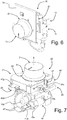
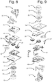
- FIGS 8 and 9 show, from different angles, the components of the timer device according to one embodiment of the invention, as well as some components of the appliance 1 already referred to previously. Visible in these figures are the tap 10, the mounting bracket 23, a first part 40 of the casing 21, a circuit arrangement 25 that equips the device, a connector 26 belonging to an external wiring system (not represented), a control or motion-transmission element 27 for a switching means of the circuit arrangement 25, a transmission member 28 co-operating with the movable part of a sensor of the arrangement 25, a further transmission member 29 which can be actuated by the ring nut 22 to turn the member 28 accordingly, a member 30 intermediate between the transmission member 29 and the ring nut 22, a second part 41 of the casing 21, a sealing element 31, which is preferably of an annular type, designed to operate between the ring nut 22 and the front surface of the wall 3, and an intermediate annular element 32, which is designed to be operatively set between the knob 12 of the tap 10 and the ring nut 22 and is forced on
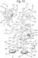
- Figures 8 and 9 are visible, at a larger scale, in Figures 10-13 .
- the tap 10 may be of a type in itself known on the market, as described in the introductory part of the present description and with reference to Figures 4 and 5 .
- the actuation element 10f may advantageously be exploited also for causing switching in closing of the microswitch MS forming part of the lighter system.
- the circuit arrangement of the device 20 includes a switching means, which performs also the functions of the aforesaid microswitch MS provided according to the known art.
- the traditional microswitch MS may be omitted, and the screw S normally used for its fixing ( Figures 3 and 4 ) may be exploited for fixing the bracket 23 to the body of the tap 10.
- the bracket 23 is made of metal and has a longitudinal member 23a rising from which is a first upright part 23b, provided with a hole 23c for the passage of a screw (not represented), for example for engagement in an internal screw 10h provided on the body of the tap 10.
- Said internal screw may advantageously be the one usually provided for the screw S for fixing the microswitch MS provided according to the known art.
- Branching off from the longitudinal member 23a are two cross members 23d, generally parallel to one another and substantially orthogonal with respect to the upright 23a, provided with respective holes 23e for securing the casing 21, for example via screws.
- At least one of the cross members 23d can have an upright terminal part 23f, which is preferably substantially orthogonal to the cross member itself, which functions as contrast or resting element with respect to the structure of the appliance 1.
- the shape illustrated for the bracket 23 is provided merely by way of example, other shapes evidently being possible, which are preferably defined according to the shape of the tap and/or of the casing 21 and/or to the structure of the appliance.
- the part 40 of the casing defined hereinafter for simplicity as “container” is substantially box-shaped and made of plastic material, with a bottom wall 40a and peripheral walls 40b that define a cavity or a seat for housing at least part of the circuit arrangement 25 and of the transmission arrangement including the transmission members 28-30, which are preferably toothed transmission members.
- one of the peripheral walls 40b closes only partially the corresponding side of the container 40, thus defining a side opening 40c ( Figure 11 ).
- an appendage 40d projects outwards, aimed at providing a first part of a connector body, visible as a whole in Figure 7 , fitted within which is the connector 26.
- one of the peripheral walls 40b has an opening or gap 40e ( Figure 11 ), the function of which will be clarified hereinafter, to which there preferably corresponds a slit 40f ( Figure 10 ) defined in the bottom wall 40a.
- the bottom wall 40a is also provided with holes 40g for fixing the casing to the bracket 23, as well as a pair of slits 40h ( Figure 10 ), which are preferably generally parallel and in a position set alongside with respect to the appendage 40d.
- the casing 21 of the device 20 is configured for coupling with the body of the tap 10, and for this purpose has a passage, in which a corresponding part of the tap may be received passing through it.
- the bottom wall 40a has a through opening 42, which is preferably, but not necessarily, substantially circular.
- the container 40 defines a hollow portion 42a, projecting within the corresponding cavity, where the opening 42 is located.
- the container 40 also defines an external recess, for housing partially, and with possibility of movement, the actuation element 10f of the tap 10.
- the bottom wall 40a and the peripheral wall 40b that has the gap 40e define together, within the container 40, the aforesaid hollow portion 42a, having an outer profile that is at least in part cylindrical.
- a part of the bottom wall 40a defines the aforesaid external recess 42b, between the opening 42 and a respective wall 40b, in particular the one provided with the gap 40e.
- the circuit arrangement 25 preferably includes a printed-circuit board (PCB), designated by 25a, which is at least partially housed within the casing 21 and mounted on which are electrical and/or electronic components, connected to tracks (not represented) made of electrically conductive material defined on the circuit board 25a.
- PCB printed-circuit board
- the circuit board 25a has a respective passage that surrounds at least in part the passage of the casing 21.
- the passage of the circuit board 25a is in the form of an opening or slot 25b having a profile at least in part similar to or congruent with that of the opening 42 of the bottom wall 40a of the container 40 and/or of the corresponding hollow portion 42a, and the circuit board 25a is mounted in a position generally close to the bottom wall 40a.
- the slot 25b extends as far as an edge of the circuit board 25a and has at least a corresponding portion shaped like an arc of circumference.
- the passage of the circuit board 25a may be circular, such as a hole, for example if the portion 42a is generally cylindrical or if it is absent.
- control circuit provided on the circuit board 25a may comprise - in general terms - the components described in WO 2010/134040 , for performing the functions described in said document and/or other specific functions envisaged according to the present invention.
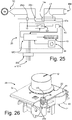
- An example of circuit will in any case be described hereinafter with reference to Figure 25 .
- an end or projecting portion 25c of the circuit board 25a provides a male electrical connector, the terminals of which are obtained from electrical tracks, in particular of an edge-connector or card-edge type, which, in the condition where the device 20 is assembled, is in a position corresponding to the appendage 40d of the container 40, provided for coupling with the external connector 26.
- the circuit arrangement 25 includes light-emitting means, which may comprise one or more emitters, for example of a LED type.
- these emitter means are mounted on a face of the circuit board 25a - here defined as upper face - in the proximity of the passage of the casing 21.
- a number of emitters 43 are provided, arranged at intervals apart around the slot 25b. Given that, in the example, the slot 25b extends as far as an edge of the circuit board 25a, the emitters 43 are arranged according to the profile of the arc-shaped part of the slot itself, preferably at substantially regular intervals.
- the circuit arrangement 25 comprises detection or sensor means, for detecting the angular position of the ring nut 22 and supplying accordingly a signal representing a time interval of supply of the burner controlled by the tap 10.
- these sensor means include a stationary component 44, preferably mounted on the upper face of the circuit board 25a.
- the sensor means are of a resistive type, such as a rotary potentiometer or trimmer, actuated by a corresponding part that may be set in rotation following upon a rotation of the ring nut.
- the signal for activation of the timing function of the device 20 is supplied to the circuit arrangement 25 by a control - element.
- this control element comprises a switching means, such as a pushbutton switch, preferably a low-power switch, in particular, for voltages ranging between 1 V and 24 V, which can be switched following upon axial displacement of the rod 11 of the tap, for example, the switch designated by 45.
- the circuit of the device 20 is prearranged also for connection to a system for lighting the burners of the appliance 1, the signal generated by switching of the control element may also be used for governing the lighter system.
- the control element represented by the pushbutton switch 45 is provided on the upper face of the circuit board 25a.
- the switch 45 is a double-contact switch.
- the motion-transmission element 27 is configured for transmitting an axial movement of the control rod 11 of the tap 10 to the switch 45, and for this purpose is mounted movable on the casing 21, in particular in a slidable way. At least one part of the motion-transmission element 27 faces the outside of the casing 21 in order to be able to interact or couple with the actuation element 10f of the tap 10. In embodiments not represented, it is also possible to provide a motion-transmission element configured for direct coupling to the rod 11.
- the element 27 has a base part 27a and an upright part 27b, the latter being shaped for engaging slidably in a vertical direction in the gap 40e ( Figure 11 ) and in the slit 40f ( Figure 10 ).
- the element 27 is coupled to the container 40 so that its base part 27a overlies the pushbutton of the switch 45 in order to be able to cause switching thereof, in particular, via further interposed elastic means (see, for reference, Figure 20 ).
- the upright part 27b of the element 27 facing the outside of the casing 21 has a seat for engagement of the element 10f of the tap, said seat being here defined by two projections 27c ( Figures 10 and 16 ) received between which is a part of the element 10f.
- the axial movement of the rod of the tap due to pressure applied on the knob 12, brings about a corresponding vertical movement of the element 27 (downwards, as viewed in Figure 7 ).
- the aforesaid elastic means, or damping means are provided, in particular having the function of operating the pushbutton of the switch 45 and compensating for possible tolerances of production and assembly and/or preventing risks of excessive stresses exerted by the element 27 on the switch 45.
- said means comprise an elastic element 46, in particular a helical spring, operatively set between the element 27 and the pushbutton of the switch 45.
- one end of the spring 46 is fitted on a pin 27d ( Figure 10 ) projecting from the lower face of the head part 27a of the element 27, and the opposite end is engaged on the pushbutton of the switch 45.
- the spring 46 is calibrated so that, beyond a certain degree of compression thereof, it will transfer to the pushbutton of the switch 45 the force necessary for switching, said spring 46 being also able to absorb or compensate for possible excessive stresses.
- the damping function can be integrated directly in the motion-transmission element, for example by providing in its body an elastically deformable part, having spring functions.
- the circuit arrangement 25 of the device includes first connection means for electrical connection to the electromagnet of the safety valve of the tap 10.
- first connection means for electrical connection to the electromagnet of the safety valve of the tap 10.
- electrical conductors or wires 47 represented schematically, for connection of the circuit of the device 20 to the electrical attachment or connector 10e of the tap 10, i.e., the attachment where the thermocouple is traditionally connected.
- Connected to the conductors or wires 47 of the arrangement 25 is a corresponding connector 47a, of a type complementary to the attachment 10e of the tap 10 and/or to the electrical connector of the electromagnet of the safety valve.
- the connector 47a is of a type designed to perform the functions of connection proper to the traditional connectors for thermocouples used on taps of the type considered herein, in particular, a connector 47a of an axial type, or of a radial type, or of a Faston type.
- the connector 47a includes two generally coaxial parts, not indicated, and in particular a central part and a peripheral part.
- the central part which is at least partially cylindrical, is made of electrically insulating material and defines at the centre an axial seat ( Figure 10 ), housed within which is a corresponding contact, connected to one of the conductors 47.
- the peripheral part, connected to the other conductor 47, is in the form of a shaped metal lamina, fitted on the central part and with a corresponding generally arched contact portion that surrounds at least partially the insulating central part, at a distance therefrom.
- the central part of the connector 47a can be inserted in the attachment 10e for the thermocouple (see Figure 7 ) so that in the corresponding axial seat there fits a terminal with central pin of the attachment 10e (see, for example, Figure 5 ), which thus electrically couples to the internal contact of the seat itself.
- the arched portion of the peripheral part of the connector 47a by exploiting a certain elasticity thereof, bears, instead, upon an external cylindrical part of the attachment 10e.
- the conductors 47 may be absent, with the connector 47a connected or associated directly to the support of the circuit arrangement 25, with said connector, support, and casing of the device 20 appropriately shaped for enabling a connection to the connector 10e of the tap 10.
- the electrical connectors such as a first connector towards the electromagnet of the safety valve of the tap and a second connector towards the thermocouple, may be of the same type or else of different types: in the latter case, the timer device can function also as "adapter" between different connectors, i.e., between a thermocouple having a first type of connector and an electromagnet or safety valve of a gas tap having a second type of electrical connector, or else a timer 20 having a first connector 25d different from a second type of connector 47a.
- the arrangement 25 likewise includes second connection means for electrical connection to the thermo-electric generator of the tap 10, i.e., the corresponding thermocouple.
- the conductors of the thermocouple - not represented - that equips the tap 10 are connected to the circuit arrangement 25a via fast-coupling connectors, which are preferably blade connectors, such as Faston connectors.
- fast-coupling connectors which are preferably blade connectors, such as Faston connectors.
- projecting from the lower face of the circuit board 25a are two blade contacts 25d+ and 25d-(hereinafter, where not strictly necessary, designated simply by 25d), in particular of a male Faston type, which are generally L-shaped and are parallel to one another.
- the contacts 25d pass through the slits 40h of the bottom 40a of the container 40 so that their contact part projects outwards, as may be seen, for example, in Figure 22 , providing an electrical connector of the device 20 for the thermocouple.
- the connectors of the thermocouple which in this case are of a female Faston type.
- connection means proper to the thermocouple are of a different type from the connection means of the thermocouple provided by the tap (here the attachment 10e of a coaxial type): the device 20 consequently functions as "adapter", as explained above.
- contacts 25d could be replaced by a cable with two conductors provided with a connector for a thermocouple.
- the circuit board 25a preferably has positioning and fixing through holes 25e, designed to couple with reliefs 401 ( Figure 11 ) of the bottom wall 40a of the container 40, said reliefs being axially hollow for receiving the screws that pass also into the holes 40g of the bottom 40a ( Figure 10 ).
- bushings 25f are preferably mounted, on the upper face of the circuit board 25a, basically having the function of spacers and/or positioning elements with respect to the casing part 41, defined hereinafter as "lid".
- the bushings 25f may possibly form part of the lid 41.
- the movable part of the position-sensor means - actuated by, or including, the shaft designated by 28b - is able to rotate about an axis that is different from the axis about which the ring nut 22 turns, in particular is substantially parallel thereto, and operatively set between the ring nut 22 and the movable part of the sensor means is a transmission arrangement; i.e., the device 20 comprises a transmission arrangement, set between the control element or ring nut 22 and the position-sensor means.
- the aforesaid transmission arrangement includes a first transmission member that is substantially coaxial to the ring nut 22 and is able to turn therewith.
- This first transmission member has an axial cavity, in which there may be received a corresponding part of the tap 10, and the ring nut 22 is coupled in a separable way to this transmission member.
- the transmission arrangement includes at least one second transmission member, which is engaged in rotation with the first rotating member and is able to set in rotation the movable part of the position-sensor means.
- the transmission arrangement comprises the rotating members previously designated by 29 and with 28, which represent the aforesaid first and second transmission members, respectively.
- the member 28 basically comprises a gear, the axis of rotation B of which is defined by a pin 28a projecting from its upper face, said pin being designed for engagement in a respective cylindrical rotation seat 41d of the lid 41 ( Figure 12 ).
- a shaft 28b Projecting, instead, from the lower face of the member 28 is a shaft 28b, coaxial to the upper pin 28a, which provides an element for actuation of the movable part of the position-sensor means.
- the shaft 28b preferably has a cross section that is at least in part square (not circular), designed to couple mechanically to an internal movable member of the potentiometer 44, partially visible in Figure 17 , where it is designated by 44a: in practice, then, the shaft 28b of the member 28 provides the element for actuation of the movable part 44a of the potentiometer or trimmer 44.
- mechanical end-of-travel means are provided for rotation of the member 28, which preferably comprise an element carried by the member itself, designed to interact with a stationary contrast element.
- a stationary contrast element projecting from the lower face of the member 28 is an arrest element 28c, designed to interfere with a fixed contrast element of the container 40.
- a contrast element of this sort is designated by 40i in Figure 18 .
- the arrest element 28c and the contrast element 40i may be shaped, for example, in such a way that the useful travel of the ring nut 22 is approximately 320°.
- the element 28c and the contrast element 40i are shaped so as to provide a point of respective mild engagement, for example so as to define an initial position of inactivity of the device 20 (for example, the element 28c may be shaped so that it can snap into the hollow seat of the element 40i).
- the angular area corresponding to a complete rotation - for example in a clockwise direction - in the proximity of the contrast element 40i defines an area or position of mechanical zero.
- This angular area which may be approximately 12° wide, has a particular meaning for operation of the device 20, in so far as, together with the ring nut 22 positioned in the aforesaid area, it is generally in a state of inactivity.
- the duration of the interval of supply of the burner increases with rotation of the ring nut 22 in a counterclockwise direction.
- means for providing a snap coupling or engagement that defines an angular position or angular area of mechanical zero may be associated to other elements of the device, such as the ring nut 22 and/or the member 29.
- the second rotating member 29 constitutes an axially hollow transmission element, which can be coupled in a separable way to the ring nut 22 and is coaxial thereto in order to turn according to the axis denoted by A in various figures, also corresponding to the axis of rotation of the stem 11 of the tap 10.
- the member 29 comprises a circular ring gear 29a, projecting from the upper face of which are engagement elements 29b.
- engagement elements 29b Preferably, at least two engagement elements 29b are provided in diametrally opposite positions.
- the engagement elements 29b have a substantially cylindrical shape.
- the transmission member 29 is rotatably supported by a corresponding portion of the casing 21, at the corresponding passage.
- a cylindrical annular part 29c projecting from the lower face of the circular ring gear 29a is a cylindrical annular part 29c, having a smaller circumference than the one defined by the teeth of the ring gear 29a.
- the cylindrical part 29c is designed to insert with minimal play or with slight interference in the through opening 42 of the bottom wall 40a of the container 40 so that it can turn therein about the axis A, sustained on the hollow portion 42a.
- the transmission arrangement also includes the intermediate member 30, prevalently located within the casing of the device 20.
- the intermediate member 30 has a respective axial cavity and is operatively set between the ring nut 22 and the transmission member 29 so as to turn therewith according to the axis A.
- the ring nut 22, prevalently located on the outside of the appliance 1, is preferably made of transparent material, for example a transparent thermoplastic material, such as polycarbonate or methacrylate, for performing functions of light guide or optical guide, in order to receive and/or transfer light radiation, in particular, from the inside to the outside of the appliance 1.
- the through cavity of the member 30 preferably has a diameter greater than that of the member 29.
- the intermediate member 30 has a generally annular shape, with an end face facing the upper face of the toothed member 29, in order to be able to rest at least partially thereon.
- an optical guide is provided - here made up of a number of parts, such as the elements 22 and 30 - preferably made of transparent thermoplastic material, for transferring a light signal from the inside of the device 20 and/or of the appliance 1 to the outside of the appliance 1.
- the member 30 performs functions of light guide or optical guide, for transfer of light radiation generated by the emitter means 43 to the ring nut 22.
- the member 30 and at least part of the ring nut 22 are made of a transparent material, for example methacrylate, or in any case a material that is able to transmit the light generated by the emitters 43.
- the diameter at the base of the member 30 is greater than the diameter defined by the teeth of the member 29 so that a peripheral annular region of the upper face of the member 30 faces directly the emitters 43, as may be noted, for example, from Figure 20 .
- the intermediate member 30 has a frustoconical outer profile, in particular with an inclination of its peripheral wall 30 1 ( Figure 14 ) substantially equal to 45° with respect to the base. In this way, the light radiation generated by the emitters 43 impinges on the annular region of the lower face of the member 30 that projects beyond the member 29.
- the light radiation is reflected within the body of the member 30 by the peripheral wall 30 1 , in a substantially orthogonal or radial direction, i.e., towards the surface of the axial cavity of the member 30.
- a corresponding portion of the ring nut 22 which can then transfer the light frontally, beyond the wall 3a of the appliance.
- the internal surface of the member 30 defines seats 30a, in the form of axial recesses, of a shape complementary to at least part of the outer profile of the engagement elements 29b of the member 29 in order to enable mutual coupling thereof that enables transmission of a rotation of the member 29 to the member 30, as may be seen, for example, in Figure 20 .
- at least two seats 30a are provided, in diametrally opposite positions, preferably having a substantially semi-cylindrical profile.
- the lid 41 of the casing has a respective bottom wall 41a, defined in which is a through opening 41b, here circular, which forms part of the aforesaid passage of the casing 21 and inserted in which is part of the tap 10.
- the through opening 41b has a diameter substantially corresponding to that of the opening 42 of the container 40 and/or substantially corresponding to the diameter of the portion of tap 10 on which it is mounted.
- the bottom wall 41a of the lid 41 also has holes 41c for the passage of the screws used for fixing the lid and the container together and/or with respect to the bracket 23, the screws also passing between the spacer bushings 25f previously mentioned.
- the cylindrical seat 41d is also defined, for receiving a corresponding portion of the pin 28a of the toothed member 28.
- the lid 41 and the container 40 are associated to one another and/or fixed via means different from the ones illustrated, such as means for mutual engagement of the lid and/or of the container, preferably of a snap-in type, or else fixed by gluing or welding, in particular, welding of a laser or vibration type, or by hot re-melting of a plastic material of at least one of the lid and the container. Coupling or fixing between the lid 41 and the container 40 is preferably of the sealed type, possibly with the aid of sealing elements set in between.
- the appendages 40d and 41g define at least part of an electrical-connector body, which houses the portion 25c of the circuit arrangement 25 on which the connector 26 is coupled (see, for reference, Figure 7 or Figure 24 , in which a part of the wiring to which the connector 26 belongs is also visible).
- the portion 25c and/or the corresponding connector body 40d, 41g, on one side, and the connector 26, on the other side, may advantageously be provided with engagement means and/or polarization or encoding means in order to enable electrical coupling only with a predefined connector 26 and/or in a unique direction.
- the polarization or encoding means may, for example, comprise seats and/or cavities and/or holes made in the circuit board 25a and/or in the connector 25c and/or in the connector body 40d, 41g, designed to couple with respective polarization or encoding means of the connector 26.
- the engagement means may, for example, comprise at least one tooth for engagement on the connector 26 and a corresponding seat for engagement on the circuit board 25a and/or the connector 25c and/or the corresponding connector body, or vice versa.
- the connector appendages or portions 40d and 41g define at least one of engagement means and polarization means, for unique coupling with the predefined connector 26. More in particular, the appendage 41g includes a tooth (see, for example, Figure 12 ) designed to couple in a corresponding seat of the body of the connector 26, whereas the appendage 40d has an insertion "key” comprising reliefs and cavities (partially visible in Figure 11 ), for coupling with a respective substantially complementary part of the connector 26.
- the connector 26 is preferably provided with elastic electrical terminals or connections, designed to contact the respective electrical terminals of the connector 25c, which are preferably made in the form of electrical tracks on the circuit board 25a, but could also be constituted by rigid metal terminals.
- the connection of the connector 26 to the corresponding wiring may, for example, be obtained by insulator-punchthrough connection means.
- the ring nut 22 has an axial cavity, in which there may be received a corresponding part of the gas tap, preferably comprising at least part of the rod 11.
- the ring nut 22 has a gripping portion 22a, which is preferably provided on the surface with knurling or the like.
- the outer profile of the gripping portion 22a is preferably substantially frustoconical, with major diameter on its face opposite to the wall 3a of the appliance, and in particular with an inclination of its peripheral wall 22 1 ( Figure 14 ) substantially of 45°.
- the gripping portion 22a defines an inclined annular wall 22 2 , in particular with an inclination substantially of 45° and opposite to that of the external peripheral wall 22 1 .
- a seat 22b is defined for the sealing element 31, which is preferably an annular gasket, of an O-ring type.
- the sealing element 31 is designed to cooperate in a sealed way with the front surface of the wall 3a of the appliance.
- a cylindrical hollow portion 22c Rising from the lower face of the gripping portion 22a is a cylindrical hollow portion 22c, on the outer surface of which seats 22d are defined, in the form of axial recesses, having a shape at least in part complementary to the outer profile of the engagement elements 29b of the toothed member 29 in order to obtain mutual coupling between them that enables transmission of a rotation of the ring nut 22 to the member 29, as may be seen, for example, in Figure 24 .
- at least two seats 22d are provided, in diametrally opposite positions, preferably having a substantially semi-cylindrical profile.
- the seats 30a of the intermediate member 30 and the seats 22d of the ring nut 22, in the form of axial recesses, are preferably such as to couple to one another or face each another so as to provide seats of a shape substantially complementary to the outer profile of the respective engagement elements 29b of the rotating member 29, in particular, seats having a substantially cylindrical profile.
- the end face 22 3 ( Figure 14 ) of the cylindrical portion 22c of the ring nut 22 opposite to the gripping portion 22a is inclined inwards; i.e., it has an inclination opposite to that of the peripheral wall 22 2 of the portion 22a, in particular an inclination substantially equal to 45° with respect to the axis of rotation.
- Figure 14 exemplifies a mode of transmission of light from an emitter 43 to the ring nut 22. It may be noted that in this figure the representation of some components of the device has been omitted, for greater clarity.
- an outer annular part of the lower face of the member 30 is set facing the emitters 43.
- the light radiation LR emitted by an emitter 43 impinges on the bottom face of the member 30 and then proceeds inside it in an axial direction, until it encounters the corresponding inclined peripheral wall 30 1 .
- the wall 30 1 hence reflects at least part of the light radiation in a substantially radial direction (i.e., a direction substantially orthogonal to that of the radiation entering the body of the member 30), in the direction of the centre of the member 30.
- one or more surfaces of the components involved may be treated for improving transfer of light radiation.
- the various walls of the optical guide could even present angles and/or conformations different from the ones exemplified, provided that the function described is guaranteed.
- the radiation propagates in the cylindrical portion 22c of the ring nut 22, fitted in the cavity of the member 30.
- the radiation proceeds in the body of the portion 22c in a radial direction, in the direction of the axis of rotation, until it encounters the inclined end face 22 3 of the cylindrical portion 22c.
- This face 22 3 now reflects at least part of the radiation within the cylindrical portion 22c, in an axial direction, until it encounters the inclined wall 22 2 defined at the top end of the axial cavity of the ring nut.
- the wall 22 2 then reflects at least part of the radiation again in a radial direction, now outwards, over the gripping portion 22a of the ring nut, towards its part that projects radially from the knob 12 of the tap.
- the radiation proceeds in the body of the gripping portion 22a until it encounters the corresponding peripheral wall 22 1 , which reflects again the radiation in an axial direction, so that it is evident for the user.
- the outer diameter of the cylindrical portion 22c is smaller than the diameter of the opening 7 provided on the wall 3a of the appliance and only slightly smaller than the diameter of the opening 41b of the lid, in such a way that the ring nut 22 can be turned manually.
- the outer diameter of the cylindrical portion 22c is also slightly smaller than the diameter of the axial cavity of the member 30 so that it can be inserted therein, with the corresponding seats 22d that fit on the part of the engagement elements 29b opposite to the part that is engaged in the seats 30a of the member 30, as may be appreciated, for example, from Figure 24 .
- the arrangement is such that a rotation imparted manually on the ring nut 22 is transmitted both to the toothed member 29 and to the intermediate member 30, given the coupling of the elements 29b of the member 29 with the seats 30a and 22d of the member 30 and of the ring nut 22, respectively. Rotation of the member 29 then brings about rotation of the member 28, with the shaft 28b, and thus variation of the adjustment value of the potentiometer 44.
- the intermediate element 32 also has a generally annular shape and is provided for being operatively mounted between the ring nut 22 and the knob 12, preferably at least partially in a concealed position, as may be seen for example in Figure 24 . It may be noted that intermediate elements similar to the element 32 are normally provided in knobs for gas taps, on the aforesaid known intermediate elements there being mounted an annular gasket, designed to operate in a sealed way on the outer surface of the appliance.
- the element 32 is pushed by a spring 32a - mounted inside the knob 12, in order to press the ring nut 22 towards the surface 3a of the appliance: in this way, the sealing element 31 of the ring nut 22 is pushed against the surface 3a.
- the element 32 may be provided with an annular gasket on its bottom face, for improving the seal between the element 32 itself and the ring nut 22.
- the knob 12 of the tap 10 has a main part that includes a cylindrical wall 12a and a top closing wall 12b, extending from a bottom face of which is a cylindrical shank 12c, substantially coaxial to the wall 12a.
- a cylindrical shank 12c defined in the shank 12c is an axial seat 12d for receiving and engaging the rod 11 of the tap 10, with a coupling such that a rotation imparted on the knob 12 will cause rotation of the rod 11.
- the diameter of the axial passage of the intermediate element 32 is slightly greater than that of the shank 12c, whereas the outer diameter of the element 32 is only slightly smaller than the inner diameter of the cylindrical wall 12a of the knob. In this way, the knob 12 can also be pressed to enable axial sliding of the rod 11 of the tap 10, with the knob itself that can slide on the element 32, the latter resting on the ring nut 22.
- the inner diameter of the axial passage of the ring nut 22 is only slightly greater than that of the shank 12c of the knob 12 and that the inner diameters of the axial passages of the members 29 and 30 are such as to enable insertion through them of the head portion 10a ( Figures 10-11 ) of the tap 10, which also passes through the openings 42 and 40b of the container 40 and of the lid 41 of the casing 21.
- Figure 18 represents a condition of partial assembly of the timer device, visible in which is the container 40 within which the circuit arrangement 25 including the circuit board 25a is located.
- Figure 19 the toothed transmission members 28 and 29 are also assembled, whilst Figure 20 also includes the intermediate member 30.
- Figures 21 and 22 represent, instead, in different views, the casing 21 assembled, with the circuit arrangement and the transmission arrangement previously described inside it. From these figures there may be appreciated the compact configuration of relatively small thickness of the casing 21, and it may be noted how the axial cavity of the transmission member 29 defines at least one respective portion of the passage for the front part of the tap.
- the transmission arrangement described thanks to the axial cavities of the members 29 and 30, enables adequate shielding of the inside of the casing 21, also in the case where the ring nut 22 is removed. It will be appreciated that the movement of the ring nut 22 is transferred to the corresponding sensor means 44 via the transmission arrangement 28-30. In this way, any direct stress on the sensor means and/or on the circuit board 25a is prevented. It will likewise be appreciated that, in the embodiment illustrated, the part of the transmission system to which the ring nut 22 - i.e., the member 29 - is associated does not touch the circuit board 25a, but is supported by a portion (42a) of the casing.
- Figure 23 shows the condition of further assembly of the casing 21 on the tap 10, by means of the bracket 23, and with the ring nut 22. It should be noted that Figure 23 - as likewise Figure 7 described previously where the knob 12 is further represented - is provided merely by way of example given that, in the actual condition where the device 20 is installed, between the ring nut 22 and the casing 21 there extends the wall 3a of the appliance 1.
- Figure 24 illustrates the device 20 in partial cross section, in this figure there being visible the transmission arrangement formed by the members 28-30 coupled together via the elements 29b of the member 29, as well as the gasket 31 set between the ring nut 22 and the front surface of the wall 3a.
- the presence of the transmission arrangement described prevents the need to associate the manual-control means of the device directly to the corresponding sensor, thereby preventing stresses on the sensor itself and/or on the circuit board on which it is mounted.
- the part of the transmission arrangement to which the ring nut 22 (i.e., the member 29) is associated not to touch in any case the circuit board, but to be supported by a portion of the casing of the device projecting within its cavity (for such a case it is hence also advantageous that the circuit board has a passage for this portion of the casing).
- the transmission arrangement envisaged according to the invention provides also a sort of "adapter” between a control means and the corresponding movement-sensor means, and especially between the control means here represented by the ring nut 22 and the sensor means represented by the potentiometer 44.
- a "custom" mechanical arrangement of the device 20 and/or of the control means can be adapted to a sensor of a "standard” type available on the market.
- the device 20 is prearranged for performing at least a function of timing of the supply of gas to the burner controlled by the tap 10, and includes for this purpose at least a timer circuit and a means for manual setting of the supply interval, here represented by the ring nut 22, which can be operated from the outside of the structure of the appliance and is substantially coaxial to the knob 12 of the tap 10.
- the knob 12 and the ring nut 22 can be turned by a user, preferably independently of one another, about the axis A, in order to enable, on the one hand, adjustment of the flow of gas admitted to the burner and, on the other hand, setting of the time of supply of the burner.
- the knob 12 is also axially movable, unlike the ring nut 22 (on the other hand, as has been mentioned, in possible variant embodiments also the ring nut 22 could translate axially).
- the timer circuit MC is implemented in the circuit arrangement 25, which likewise includes first switching means Q1, which can be controlled for causing interruption of electrical supply to the solenoid EM of the safety valve of the tap 10, upon expiry of the time interval set via the ring nut 22, and thus cause passage of the aforesaid valve into the respective closed condition.
- the first switching means Q1 are preferably connected in series between the thermocouple TC provided for the tap 10 and the electromagnet EM of the corresponding safety valve.
- the timer circuit MC can be obtained in any known way, for example including, in the circuit arrangement 25, a commercially available microcontroller provided with clock or timer function, which can preferably be supplied with a low d.c. voltage (for example 3 - 12 Vdc) via a supply stage or stabilized power supply.
- the device 20 is preferably a low-voltage device.
- the aforesaid microcontroller MC in which the program or software for control of the device can be implemented, is connected in signal communication to the position-sensor means, here represented by the potentiometer 44, from which the information regarding the time interval set is obtained.
- the first switching means Q1 preferably include at least one switch that can be controlled for opening or varying the electrical circuit of the thermocouple TC, when the time interval in which the burner 5a is to remain lit set via the ring nut 22 has elapsed.
- the controllable switch may be of an electro-mechanical type, for example a relay, or else of an electronic type, for example a MOSFET, and is preferably, but not necessarily, of a normally open type, switchable via a pulse or signal governed by the timer circuit MC.
- the switch Q1 is an electronic switch, in particular a MOSFET with extremely low channel resistance, set in series to the thermocouple TC-electromagnet EM circuit. A switch of this sort guarantees, in the case of conduction an extremely low resistance of the circuit and enables requirements of miniaturization to be met.
- the switching means may include a device or circuit configured for varying the electrical circuit of the thermocouple, for example a load (such as a resistance), which, when rendered active, reduces the current to the electromagnet EM.
- a load such as a resistance
- the device 20 is also prearranged for the purposes of control of a lighter system.
- the circuit part regarding the lighter system can be obtained in any known way, and is not necessarily implemented in the circuit arrangement 25.
- the circuit arrangement 25 of the device can include second control means or controllable switches, which are preferably of higher power than the first switching means Q1, in particular for a 220-V mains supply voltage, in order to control directly a lighter module (for example, for connecting in series two terminals thereof). Also these further switching means, which are preferably of a normally open type, are switchable via a pulse or signal generated by the arrangement 25.
- the potentiometer 44 basically has the function of detecting the position, among a plurality of possible positions, assumed by the manual-control means represented by the ring nut 22, this position representing the duration of the time interval set.
- the stationary component 44 is constituted by a rotary potentiometer, in particular of a resistive type, preferably of the type designed to be mounted and/or welded directly on a circuit board 25a, such as a commercial trimmer, but its functions may be evidently obtained via other electrical and/or electronic components, such as for example optical or magnetic encoders and sensors.
- the actuation element of the sensor means do not necessarily have to be represented by a rotary shaft, such as the shaft 28b, it being possible to obtain it with some other type of movable element.
- the emitters 43 which are preferably distributed in a circle around the head portion of the tap 10, bring about lighting-up of the ring nut 22, which is made of transparent plastic material, or in any case a material designed to function as light guide.
- the ring nut 22 which is made of transparent plastic material, or in any case a material designed to function as light guide.
- other mechanical parts for transmission of the rotational movement - at least the intermediate member 30 and preferably also the toothed member 29 - are preferably made of a similar material, for example polycarbonate, in order to function as optical guide.
- the light generated by the emitters 43 is visible from outside the casing 21.
- the light warnings, generated by the emitters 43 under the control of the timer circuit MC are useful for a user of the device 20. For example:
- warning means of some other type for example of an acoustic type, such as the buzzer BZ.
- different acoustic signals may indicate different events, such as confirmation of programming, approach of expiry of the supply time set, effective end of the supply time set.
- Figure 26 illustrates a variant whereby, in addition or as an alternative to the emitters 43, the circuit arrangement 25 includes at least one emitter 43', associated to which is a stationary light guide LG.
- the emitter 43' is directly mounted on the circuit board 25a and, in a position corresponding thereto, the lid 41 of the casing defines a positioning seat 41h for the light guide LG, which projects or gives out on the outside of the casing 21.
- the wall 3a defines an opening or window 3b for viewing the light guide LG.
- the light guide LG may be absent, with the emitter 43' mounted or configured so as to project directly on the outside of the casing, within a purposely shaped seat 41h, possibly with associated sealing means, such as a perimetral gasket.
- the light guide LG may extend in the opening or window 3b of the wall 3a, preferably with further sealing means between the light guide LG and the wall 3a, or else there may be provided a further optical guide or transparent element associated in a sealed way to the wall 3a.
- the emitter 43' may also be in a position that is more raised with respect to the plane defined by the circuit board 25a, for example by means of its terminals, in which case the light guide LG may have a more contained axial development as compared to the case exemplified. In the limit, the emitter 43' itself could project slightly on the outside of a corresponding hole of the casing 21, in an area corresponding to the window 3b.
- the control element, here represented by the switch 45, of the circuit arrangement 25 basically has the function of generating the command signal that the microcontroller circuit MC handles for determining or controlling initial closing of the switch Q1 and start-up or otherwise of a time count.
- the signal generated by the switch 45 can also be used by the arrangement 25, and, in particular, by its microcontroller MC, for generating the switching pulse of the control means associated to the circuit of the lighter system.
- Assembly of the device 20 is very simple. Once the casing 21 has been assembled on the bracket 23, the latter is fixed to the body of the corresponding tap 10, already mounted on the part 2 of the structure of the appliance 1. The head portion 10a of the tap is thus inserted in the through opening of the casing 21, with the actuation element 10f of the tap that is located in a position corresponding to the recess 42b of the container 40 (see, for reference, Figures 22-23 ), coupled to the motion-transmission element 27 of the device 20.
- the connector 47a is connected to the corresponding attachment 10e of the tap, whereas the conductors of the thermocouple TC are connected to the blade contacts 25d ( Figure 22 ).
- the ring nut 22 is fitted through the through opening 7 of the wall 3a of the structure so that its cylindrical bottom portion 22c is inserted in the toothed member 29, thus obtaining also coupling between the engagement elements 29b and the seats 22d.
- the knob 12 coupled to the stem 11 of the tap is the knob 12, on the shank 12c of which the element 32 has been previously fitted.
- the coupling between the stem 11 and the shank 12c is configured for enabling removal of the knob 12 and of the ring nut 22 itself by the user, for example for cleaning.
- General operation of the device may be at least in part similar to the one described in the document No. WO 2010/134040 , to which the reader is referred.
- the user has to turn the ring nut 22 for setting the desired time, for example ranging between 1 and 120 minutes.
- the user then turns the knob 12 and presses it in order to bring about initial opening of the safety valve and activation of the gas lighter.
- the pressure exerted on the knob 12 causes axial displacement of the stem 11 and of the actuation element 10f, and hence movement of the motion-transmission element 27, with consequent switching of the control element represented by the switch 45.
- the signal generated by the switch 45 is used by the control logic of the device 20 for controlling closing of the switching means Q1 provided on the circuit arrangement 25, connected in series between the thermocouple TC and the electromagnet EM of the safety valve, in order to start counting of the time and generate the command signal of the switch associated to the lighter system, when this function is envisaged.
- the control logic At the end of the time interval set via the ring nut 22, the control logic generates a new signal of switching of the switching means Q1, which in this way open the circuit of the electromagnet EM, with consequent closing of the safety valve of the tap 1. The burner is thus turned off once the pre-set time has elapsed.
- the device 20 preferably has a predefined position of non-intervention in order to enable normal use of the tap 10 and of the corresponding burner without activation of the timing function.
- This position may conveniently be represented by an angular position of "zero" of the ring nut 22, which will be purposely provided with suitable indications.
- the ring nut 22 is in this position, detected via the transmission arrangement 28-30 and the sensor 44, the functions of the circuit that are associated to the time count will not be active.
- pressure on the knob 12 will cause, in the ways already described above, generation of the signal that determines closing of the switching means in series between the thermocouple and the electromagnet in order to guarantee the electrical continuity necessary for opening the safety valve, and/or will cause generation of a signal for control of the lighter module.
- control logic of the device 20 envisages that programming will be carried out by the user after the flame to the burner 5a has already been lit.
- the user has to carry out lighting of the burner in the way described above (turn the knob 12 and press it, with consequent switching of the switch 45 and activation of the lighter system).
- the device 20 is activated in a programming mode, signalled, for example, by a fast flashing of the ring nut 22.
- the supply of gas proceeds in a traditional way (i.e., without timed turning-off), for example with the ring nut 22 lit up continuously via the emitters 43.
- the user turns the ring nut 22 and then presses the knob 12 as a confirmation of programming; in this case, the device can signal confirmation of programming (for example, acoustically or with a fast flashing of the ring nut) and start-up of the countdown (with flashing of the ring nut that, for example, becomes slower).
- confirmation of programming for example, acoustically or with a fast flashing of the ring nut
- start-up of the countdown with flashing of the ring nut that, for example, becomes slower.
- Block 101 is the starting block and highlights the condition of flame off and device 20 not programmed, i.e., in a quiescent state.
- Block 102 represents the step of ignition of the burner, which can be obtained by turning and pressing the knob 12 of the tap 10: rotation enables an initial flow of gas to the burner, whilst pressure exerted on the knob brings about switching of the switch 45, preferably activating a lighter module.
- Block 103 represents the condition of flame lit on the burner, following upon which the device 20 is activated or can be activated in a programming mode. In a possible embodiment, activation in said mode is determined by switching of the switch 45 (block 102), detected by the control circuit of the device 20.
- passage to the programming mode is determined by detection of the effective ignition of the flame, inferred, for example, from the signal generated by the thermocouple.
- Activation in the programming mode is signalled to the user, for example via a fast flashing of the emitters 43, which can be detected on the ring nut 22.
- Block 104 is a testing block, with which a check is made to verify whether the user has carried out, within a given time, programming of the device 20 by turning the ring nut 22 beyond the zero position.
- the notification may be of a visual type, via suitable flashing of the ring nut, and/or acoustic type, if the device is provided, for example, with a buzzer.
- Control then passes to block 110, with which the timer circuit MC starts countdown of the time of supply of the burner, preferably with a change of state of the warning light, for example, a slow flashing of the emitters 43.
- Block 111 expresses the fact that a time of forewarning of end of supply of gas to the burner has elapsed, which may depend upon the total time set via the ring nut 22.
- a suitable visual and/or acoustic warning for example a continuous flashing of the emitters 43 and/or two prolonged beeps separated from one another (if the buzzer is envisaged).
- the device 20 sets itself in a quiescent state.
- the warning for activation of the programming mode is issued, such as a fast flashing of the emitters 43, and the device remains in the wait state, for a given time interval, awaiting further confirmation of programming, for example obtained with a brief pressure exerted on the knob 12 of the tap, detected in block 116.
- Control then returns to block 109, for confirmation and notification that reprogramming has been carried out.
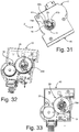
- FIGS 28-33 illustrate further possible variant embodiments.
- the same reference numbers as those of the previous figures are used to designate elements that are technically equivalent to the ones already represented.
- the tap 10 has a general configuration different from that of the previous figures, but the basic characteristics of the invention remain unchanged.
- these coupling means comprise at least one part 23, which projects downwards from the casing 21 (here from the container 40), in a direction preferably substantially axial and parallel to the axis of the passage (42) that receives part of the tap 10.
- the coupling part 23 preferably includes at least one member 23g for engagement to the body of the tap 10, in particular in an area of the rear portion - 10b of the tap.
- the engagement member 23g may include, as in the example, an elastically deformable tab, defined on which is a tooth (visible in Figure 29 ) designed to engage with the body of the tap 10.
- the part 23 may, for example, be made of plastic and/or metal material.
- the part 23 comprises a generally tubular initial stretch 23f, in the proximity of the passage 42 of the casing, so as to gird at least part of the body of the tap 10 in order to improve further the positioning between the device and the tap.
- the part 23 may also be made of a single piece with a part of the casing 21, such as the container 40, or else fixed thereto, for example via screws or the like, or else again a part of the casing 21 may be overmoulded on the part 23, whether this be made of plastic or metal material.
- the tap 10 has a structure different from the one described previously, and here is without the actuation element 10f and the shaft 10g.
- the device 20 may not perform the function of control of a lighter system.
- the rod 11 of the tap of Figures 28-29 - which in any case can translate axially - there may be associated an element performing the functions of the element previously designated by 10f.
- Figures 28-33 illustrate also a further variant of the invention, aimed at enabling functional calibration of the gas tap.
- some gas taps envisage, in particular, in the front area of their body close to the rod 11, an adjustment element, typically a screw member, for example for the so-called “minimum flame” adjustment or adjustment of the flame in relation to the type of gas.
- the device according to the invention is configured for enabling a convenient access to said adjustment element, even without the need to separate the casing 21 from the body of the tap and/or from the structure of the appliance 1.
- the tap 10 of Figure 28 has an adjustment element of this sort, represented by a screw member 10i, generally parallel to the rod 11 and accessible from the front 10a of the body of the tap 10, in particular, via the opening 7 (see, for reference, Figure 2 ) of the appliance 1.
- an adjustment element of this sort represented by a screw member 10i, generally parallel to the rod 11 and accessible from the front 10a of the body of the tap 10, in particular, via the opening 7 (see, for reference, Figure 2 ) of the appliance 1.
- At least one of the casing of the device and at least an internal element of the device and/or of the transmission arrangement of the device is configured for enabling a convenient accessibility to said member 10i, for example via a screwdriver or similar tool.
- part of the casing for example at least its lid 41
- the lid 41 has a recess 41i, having a generally semicircular or at least in part circular profile, which is defined radially with respect to its through opening 41a.
- the recess 29d may be clearly seen in Figures 32-33 , where also the representation of the lid 41 and of the member 30 has been omitted.
- the recesses 29d and 30b are defined on the members themselves in corresponding and axially aligned positions.
- the members 29 and 30 (which are coupled together in motion) can be brought to assume an angular position in which the corresponding recesses 29d and 30b are axially aligned to the head of the screw member 10i.
- said angular position is predefined and corresponds to the "zero" position of the ring nut 22, i.e., the position of non-intervention of the device 20.
- the operator simply has to bring the ring nut 22 into the corresponding zero position, where the recesses 29d and 30b of the members 29 and 20 are axially aligned to the screw member 10i.
- the knob 12 of the tap 10 and the ring nut 22 can be removed, as illustrated in Figures 30-31 .
- the opening 7 see, for reference, Figure 2
- the recess 41i of the lid 41 if said recess is provided
- the head of the adjustment member 10i is accessible from the outside of the structure of the appliance 1.
- the recess 41i of the lid 41 will be in a position axially corresponding to that of the screw member 10i.
- a passage aimed at enabling access to a member for adjustment or calibration of the gas tap may be defined in some other position, not necessarily coinciding with the passage 42, for example a circular passage, involving, for example, also the circuit board 25a and/or the member 28.
- the body 40 and the lid 41 may be shaped so as to have two tubular elements facing the inside of the casing 21, which fit to their facing ends to form a single passage duct, preferably a closed duct inside the casing 21, for reasons of protection and/or hermetic seal.
- the circuit board 25a can have a through hole in a position corresponding to one of said tubular elements.
- control element 45 there are associated both activation of the lighter system, and the functions of the device 20 linked to timing, but it is clear that even a number of control elements may be provided, such as two separate contacts or switches.
- the control element connected to the timing can be switched via the ring nut 22, which in this case will be mounted axially movable.
- the device 20 may not perform functions linked to lighting of the burner.
- control means amongst which the switch Q1, designed to modify the state of the electrical connection between the electrical-connection means 47 and 25d, i.e., to open the thermocouple-solenoid electrical circuit when the time interval set via the ring nut 22 has elapsed.
- the control means may be prearranged for modifying the state of the connection referred to above, without necessarily opening the aforesaid circuit, but simply varying it (for example, by inserting in parallel to the thermocouple a load or a resistance that reduces the current to the solenoid).
- the means for detecting the movement of the ring nut 22, associated to the transmission arrangement are represented by a rotary potentiometer or trimmer, but in possible variants it is possible to provide a linear potentiometer, with a movement of the corresponding movable part along a respective axis, in particular orthogonal to the axis A, for example envisaging a pinion-and-rack transmission system.
- the rotary potentiometer previously described has a seat engaged in which is the element 28b of the member 28, whereas in the case of a linear potentiometer this would preferably have a slider in relief, operatively coupled - for example - to a rack element engaged to a toothing of the member 28, which functions in this case as pinion.
- the device 20 could even comprise only just some of the parts or functions described above.
Landscapes
- Engineering & Computer Science (AREA)
- Chemical & Material Sciences (AREA)
- Combustion & Propulsion (AREA)
- Mechanical Engineering (AREA)
- General Engineering & Computer Science (AREA)
- Feeding And Controlling Fuel (AREA)
- Control Of Combustion (AREA)
Priority Applications (2)
| Application Number | Priority Date | Filing Date | Title |
|---|---|---|---|
| PL13735442T PL2856029T3 (pl) | 2012-05-25 | 2013-05-24 | Urządzenie sterujące do kurków gazowych |
| SI201331638T SI2856029T1 (sl) | 2012-05-25 | 2013-05-24 | Nadzorna naprava za plinske pipe |
Applications Claiming Priority (2)
| Application Number | Priority Date | Filing Date | Title |
|---|---|---|---|
| IT000455A ITTO20120455A1 (it) | 2012-05-25 | 2012-05-25 | Dispositivo di controllo per rubinetti di gas |
| PCT/IB2013/054298 WO2013175438A1 (en) | 2012-05-25 | 2013-05-24 | Control device for gas taps |
Publications (2)
| Publication Number | Publication Date |
|---|---|
| EP2856029A1 EP2856029A1 (en) | 2015-04-08 |
| EP2856029B1 true EP2856029B1 (en) | 2019-09-11 |
Family
ID=46466756
Family Applications (1)
| Application Number | Title | Priority Date | Filing Date |
|---|---|---|---|
| EP13735442.9A Active EP2856029B1 (en) | 2012-05-25 | 2013-05-24 | Control device for gas taps |
Country Status (8)
| Country | Link |
|---|---|
| US (1) | US9696041B2 (pl) |
| EP (1) | EP2856029B1 (pl) |
| CN (1) | CN104508377B (pl) |
| ES (1) | ES2770659T3 (pl) |
| IT (1) | ITTO20120455A1 (pl) |
| PL (1) | PL2856029T3 (pl) |
| SI (1) | SI2856029T1 (pl) |
| WO (1) | WO2013175438A1 (pl) |
Families Citing this family (22)
| Publication number | Priority date | Publication date | Assignee | Title |
|---|---|---|---|---|
| KR102513487B1 (ko) * | 2016-08-10 | 2023-03-23 | 삼성전자주식회사 | 조리기기 |
| US10605462B2 (en) * | 2016-11-15 | 2020-03-31 | Haier Us Appliance Solutions, Inc. | Main top of a cooktop appliance |
| CN106338092B (zh) * | 2016-11-18 | 2019-09-03 | 佛山市人百金贸易有限公司 | 一种燃气灶调节装置及燃气灶 |
| US10935249B2 (en) | 2017-02-17 | 2021-03-02 | Lg Electronics Inc. | Knob assembly for cook top |
| US11635782B2 (en) | 2017-02-17 | 2023-04-25 | Lg Electronics Inc. | Knob assembly for cook top |
| US10732666B2 (en) | 2017-02-17 | 2020-08-04 | Lg Electronics Inc. | Knob assembly for cook top |
| KR101913927B1 (ko) | 2017-02-17 | 2018-10-31 | 엘지전자 주식회사 | 노브 조립체 및 이를 구비하는 조리기기 |
| KR102106843B1 (ko) * | 2017-02-17 | 2020-05-06 | 엘지전자 주식회사 | 노브 조립체 및 이를 포함하는 조리기기 |
| KR102174849B1 (ko) | 2017-07-26 | 2020-11-05 | 엘지전자 주식회사 | 유니버설 조인트와 이를 구비하는 노브 조립체 및 가전기기 |
| KR101912932B1 (ko) | 2017-02-22 | 2018-10-29 | 엘지전자 주식회사 | 디스플레이기를 구비하는 노브 조립체 및 이를 포함하는 조리기기 |
| US11231180B2 (en) | 2017-02-17 | 2022-01-25 | Lg Electronics Inc. | Knob assembly for cook top |
| KR102101415B1 (ko) | 2017-07-24 | 2020-04-16 | 엘지전자 주식회사 | 노브 조립체 및 이를 구비하는 가전기기 |
| EP3627276B1 (en) * | 2017-02-17 | 2022-08-31 | LG Electronics Inc. | Joint and knob assembly and appliance having joint and knob assembly |
| KR102103016B1 (ko) | 2017-02-17 | 2020-04-21 | 엘지전자 주식회사 | 노브 조립체 및 이를 포함하는 조리기기 |
| EP3367003B1 (en) | 2017-02-22 | 2023-04-05 | LG Electronics Inc. | Knob assembly for cook top |
| KR102106840B1 (ko) | 2017-02-22 | 2020-05-06 | 엘지전자 주식회사 | 노브 조립체 및 이를 포함하는 조리기기 |
| IT201700037451A1 (it) * | 2017-04-05 | 2018-10-05 | Castfutura Spa | Dispositivo di comando di accensione di una fiamma per bruciatori o simili predisposto per funzionare in presenza di forti ed importanti tracimazioni di liquidi e catenaria costituita da una pluralita' di detti dipositivi |
| EP3396254B1 (en) * | 2017-04-27 | 2019-11-27 | Electrolux Appliances Aktiebolag | Gas cooking hob comprising a control element |
| IT201700057665A1 (it) | 2017-05-26 | 2018-11-26 | Defendi Italy Srl | Gruppo valvola del gas perfezionato |
| CN110375092B (zh) * | 2019-06-27 | 2021-02-26 | 宁波方太厨具有限公司 | 一种燃气分配装置及应用该装置的燃气热水器 |
| CA3107299A1 (en) | 2020-01-31 | 2021-07-31 | Rinnai America Corporation | Vent attachment for a tankless water heater |
| CN119713325B (zh) * | 2025-02-27 | 2025-07-11 | 广东万家乐燃气具有限公司 | 一种燃气灶及其手自一体控制方法、设备及存储介质 |
Citations (4)
| Publication number | Priority date | Publication date | Assignee | Title |
|---|---|---|---|---|
| US20020094498A1 (en) * | 2000-08-17 | 2002-07-18 | Jorge Rodriguez-Rodriguez | Programmable burner for gas stoves |
| US20060234177A1 (en) * | 2005-04-19 | 2006-10-19 | Shih-Szu Yu | Time knob for gas and electric heater |
| WO2010134040A1 (en) * | 2009-05-20 | 2010-11-25 | Eltek S.P.A. | Device for controlling gas supply to a burner |
| WO2011096902A2 (en) * | 2010-02-05 | 2011-08-11 | Emil Benko | Timer of a household gas burner |
Family Cites Families (14)
| Publication number | Priority date | Publication date | Assignee | Title |
|---|---|---|---|---|
| US5575638A (en) * | 1994-03-29 | 1996-11-19 | Thermador Corporation | Stove burner simmer control |
| IT1283738B1 (it) * | 1996-04-15 | 1998-04-30 | Whirpool Europ S R L | Apparecchio funzionante a gas per il riscaldamento e/o cottura di alimenti e simili |
| US6705533B2 (en) * | 2001-04-20 | 2004-03-16 | Gas Research Institute | Digital modulation for a gas-fired heater |
| US7467639B2 (en) * | 2003-03-28 | 2008-12-23 | General Electric Company | Systems and methods for controlling gas flow |
| US7322616B2 (en) * | 2005-01-07 | 2008-01-29 | Mueller Gas Products | Tubing connecting device |
| CN200989615Y (zh) * | 2006-08-08 | 2007-12-12 | 高国民 | 一种新型灶具用燃气控制装置 |
| US8475162B2 (en) * | 2009-11-30 | 2013-07-02 | Whirlpool Corporation | Smart gas burner system for cooking appliance |
| CN201688015U (zh) * | 2010-03-16 | 2010-12-29 | 黄飞 | 燃气管道阀门定时关闭装置 |
| EP2390573A1 (en) * | 2010-05-27 | 2011-11-30 | Electrolux Home Products Corporation N.V. | Gas-fired kitchen appliance |
| PL2659190T3 (pl) * | 2010-12-31 | 2015-04-30 | Arcelik As | Urządzenie gospodarstwa domowego zawierające pokrętło, którego zewnętrzne obrzeże jest podświetlane |
| US9543945B2 (en) * | 2011-06-20 | 2017-01-10 | Benjamin H. Seigler | Fire sentry |
| US9103553B2 (en) * | 2012-12-05 | 2015-08-11 | Bsh Home Appliances Corporation | Domestic cooking appliance with adjustable gas switch mounting system |
| US20150198336A1 (en) * | 2014-01-10 | 2015-07-16 | Jürgen Koch | Gas orifice holder |
| TW201610368A (zh) * | 2014-09-03 | 2016-03-16 | Chin Chu Technical Consulting & Services Co Ltd | 瓦斯器具之安全定時控制裝置 |
-
2012
- 2012-05-25 IT IT000455A patent/ITTO20120455A1/it unknown
-
2013
- 2013-05-24 CN CN201380027328.6A patent/CN104508377B/zh not_active Expired - Fee Related
- 2013-05-24 PL PL13735442T patent/PL2856029T3/pl unknown
- 2013-05-24 ES ES13735442T patent/ES2770659T3/es active Active
- 2013-05-24 SI SI201331638T patent/SI2856029T1/sl unknown
- 2013-05-24 WO PCT/IB2013/054298 patent/WO2013175438A1/en not_active Ceased
- 2013-05-24 EP EP13735442.9A patent/EP2856029B1/en active Active
- 2013-05-24 US US14/403,879 patent/US9696041B2/en not_active Expired - Fee Related
Patent Citations (4)
| Publication number | Priority date | Publication date | Assignee | Title |
|---|---|---|---|---|
| US20020094498A1 (en) * | 2000-08-17 | 2002-07-18 | Jorge Rodriguez-Rodriguez | Programmable burner for gas stoves |
| US20060234177A1 (en) * | 2005-04-19 | 2006-10-19 | Shih-Szu Yu | Time knob for gas and electric heater |
| WO2010134040A1 (en) * | 2009-05-20 | 2010-11-25 | Eltek S.P.A. | Device for controlling gas supply to a burner |
| WO2011096902A2 (en) * | 2010-02-05 | 2011-08-11 | Emil Benko | Timer of a household gas burner |
Also Published As
| Publication number | Publication date |
|---|---|
| US9696041B2 (en) | 2017-07-04 |
| PL2856029T3 (pl) | 2020-05-18 |
| US20150153047A1 (en) | 2015-06-04 |
| EP2856029A1 (en) | 2015-04-08 |
| WO2013175438A1 (en) | 2013-11-28 |
| ITTO20120455A1 (it) | 2013-11-26 |
| CN104508377B (zh) | 2017-05-24 |
| CN104508377A (zh) | 2015-04-08 |
| ES2770659T3 (es) | 2020-07-02 |
| SI2856029T1 (sl) | 2020-07-31 |
Similar Documents
| Publication | Publication Date | Title |
|---|---|---|
| US9696041B2 (en) | Control device for gas taps | |
| EP2856034B1 (en) | Control device for gas taps | |
| EP2856030B1 (en) | Gas appliance control device | |
| EP2856033B1 (en) | Control device for gas taps | |
| US9347665B2 (en) | Device for controlling gas supply to a burner | |
| WO2022160470A1 (zh) | 旋塞阀和燃气灶 | |
| JP4136718B2 (ja) | 調理器 | |
| CN113394043A (zh) | 能电控及手控旋转的燃气具旋钮 | |
| WO2026083181A1 (en) | Knob for a household appliance | |
| WO2022066117A2 (en) | Rotary switch system for gas-burning stoves |
Legal Events
| Date | Code | Title | Description |
|---|---|---|---|
| PUAI | Public reference made under article 153(3) epc to a published international application that has entered the european phase |
Free format text: ORIGINAL CODE: 0009012 |
|
| 17P | Request for examination filed |
Effective date: 20141121 |
|
| AK | Designated contracting states |
Kind code of ref document: A1 Designated state(s): AL AT BE BG CH CY CZ DE DK EE ES FI FR GB GR HR HU IE IS IT LI LT LU LV MC MK MT NL NO PL PT RO RS SE SI SK SM TR |
|
| AX | Request for extension of the european patent |
Extension state: BA ME |
|
| DAX | Request for extension of the european patent (deleted) | ||
| STAA | Information on the status of an ep patent application or granted ep patent |
Free format text: STATUS: EXAMINATION IS IN PROGRESS |
|
| 17Q | First examination report despatched |
Effective date: 20180605 |
|
| GRAP | Despatch of communication of intention to grant a patent |
Free format text: ORIGINAL CODE: EPIDOSNIGR1 |
|
| STAA | Information on the status of an ep patent application or granted ep patent |
Free format text: STATUS: GRANT OF PATENT IS INTENDED |
|
| INTG | Intention to grant announced |
Effective date: 20190405 |
|
| GRAS | Grant fee paid |
Free format text: ORIGINAL CODE: EPIDOSNIGR3 |
|
| GRAA | (expected) grant |
Free format text: ORIGINAL CODE: 0009210 |
|
| STAA | Information on the status of an ep patent application or granted ep patent |
Free format text: STATUS: THE PATENT HAS BEEN GRANTED |
|
| AK | Designated contracting states |
Kind code of ref document: B1 Designated state(s): AL AT BE BG CH CY CZ DE DK EE ES FI FR GB GR HR HU IE IS IT LI LT LU LV MC MK MT NL NO PL PT RO RS SE SI SK SM TR |
|
| REG | Reference to a national code |
Ref country code: GB Ref legal event code: FG4D |
|
| REG | Reference to a national code |
Ref country code: CH Ref legal event code: EP |
|
| REG | Reference to a national code |
Ref country code: AT Ref legal event code: REF Ref document number: 1178904 Country of ref document: AT Kind code of ref document: T Effective date: 20190915 |
|
| REG | Reference to a national code |
Ref country code: DE Ref legal event code: R096 Ref document number: 602013060358 Country of ref document: DE Ref country code: IE Ref legal event code: FG4D |
|
| REG | Reference to a national code |
Ref country code: NL Ref legal event code: MP Effective date: 20190911 |
|
| REG | Reference to a national code |
Ref country code: LT Ref legal event code: MG4D |
|
| PG25 | Lapsed in a contracting state [announced via postgrant information from national office to epo] |
Ref country code: NO Free format text: LAPSE BECAUSE OF FAILURE TO SUBMIT A TRANSLATION OF THE DESCRIPTION OR TO PAY THE FEE WITHIN THE PRESCRIBED TIME-LIMIT Effective date: 20191211 Ref country code: BG Free format text: LAPSE BECAUSE OF FAILURE TO SUBMIT A TRANSLATION OF THE DESCRIPTION OR TO PAY THE FEE WITHIN THE PRESCRIBED TIME-LIMIT Effective date: 20191211 Ref country code: LT Free format text: LAPSE BECAUSE OF FAILURE TO SUBMIT A TRANSLATION OF THE DESCRIPTION OR TO PAY THE FEE WITHIN THE PRESCRIBED TIME-LIMIT Effective date: 20190911 Ref country code: HR Free format text: LAPSE BECAUSE OF FAILURE TO SUBMIT A TRANSLATION OF THE DESCRIPTION OR TO PAY THE FEE WITHIN THE PRESCRIBED TIME-LIMIT Effective date: 20190911 Ref country code: SE Free format text: LAPSE BECAUSE OF FAILURE TO SUBMIT A TRANSLATION OF THE DESCRIPTION OR TO PAY THE FEE WITHIN THE PRESCRIBED TIME-LIMIT Effective date: 20190911 Ref country code: FI Free format text: LAPSE BECAUSE OF FAILURE TO SUBMIT A TRANSLATION OF THE DESCRIPTION OR TO PAY THE FEE WITHIN THE PRESCRIBED TIME-LIMIT Effective date: 20190911 |
|
| PG25 | Lapsed in a contracting state [announced via postgrant information from national office to epo] |
Ref country code: AL Free format text: LAPSE BECAUSE OF FAILURE TO SUBMIT A TRANSLATION OF THE DESCRIPTION OR TO PAY THE FEE WITHIN THE PRESCRIBED TIME-LIMIT Effective date: 20190911 Ref country code: GR Free format text: LAPSE BECAUSE OF FAILURE TO SUBMIT A TRANSLATION OF THE DESCRIPTION OR TO PAY THE FEE WITHIN THE PRESCRIBED TIME-LIMIT Effective date: 20191212 Ref country code: RS Free format text: LAPSE BECAUSE OF FAILURE TO SUBMIT A TRANSLATION OF THE DESCRIPTION OR TO PAY THE FEE WITHIN THE PRESCRIBED TIME-LIMIT Effective date: 20190911 Ref country code: LV Free format text: LAPSE BECAUSE OF FAILURE TO SUBMIT A TRANSLATION OF THE DESCRIPTION OR TO PAY THE FEE WITHIN THE PRESCRIBED TIME-LIMIT Effective date: 20190911 |
|
| REG | Reference to a national code |
Ref country code: AT Ref legal event code: MK05 Ref document number: 1178904 Country of ref document: AT Kind code of ref document: T Effective date: 20190911 |
|
| PG25 | Lapsed in a contracting state [announced via postgrant information from national office to epo] |
Ref country code: PT Free format text: LAPSE BECAUSE OF FAILURE TO SUBMIT A TRANSLATION OF THE DESCRIPTION OR TO PAY THE FEE WITHIN THE PRESCRIBED TIME-LIMIT Effective date: 20200113 Ref country code: RO Free format text: LAPSE BECAUSE OF FAILURE TO SUBMIT A TRANSLATION OF THE DESCRIPTION OR TO PAY THE FEE WITHIN THE PRESCRIBED TIME-LIMIT Effective date: 20190911 Ref country code: AT Free format text: LAPSE BECAUSE OF FAILURE TO SUBMIT A TRANSLATION OF THE DESCRIPTION OR TO PAY THE FEE WITHIN THE PRESCRIBED TIME-LIMIT Effective date: 20190911 Ref country code: IT Free format text: LAPSE BECAUSE OF FAILURE TO SUBMIT A TRANSLATION OF THE DESCRIPTION OR TO PAY THE FEE WITHIN THE PRESCRIBED TIME-LIMIT Effective date: 20190911 Ref country code: EE Free format text: LAPSE BECAUSE OF FAILURE TO SUBMIT A TRANSLATION OF THE DESCRIPTION OR TO PAY THE FEE WITHIN THE PRESCRIBED TIME-LIMIT Effective date: 20190911 Ref country code: NL Free format text: LAPSE BECAUSE OF FAILURE TO SUBMIT A TRANSLATION OF THE DESCRIPTION OR TO PAY THE FEE WITHIN THE PRESCRIBED TIME-LIMIT Effective date: 20190911 |
|
| PG25 | Lapsed in a contracting state [announced via postgrant information from national office to epo] |
Ref country code: IS Free format text: LAPSE BECAUSE OF FAILURE TO SUBMIT A TRANSLATION OF THE DESCRIPTION OR TO PAY THE FEE WITHIN THE PRESCRIBED TIME-LIMIT Effective date: 20200224 Ref country code: SK Free format text: LAPSE BECAUSE OF FAILURE TO SUBMIT A TRANSLATION OF THE DESCRIPTION OR TO PAY THE FEE WITHIN THE PRESCRIBED TIME-LIMIT Effective date: 20190911 Ref country code: SM Free format text: LAPSE BECAUSE OF FAILURE TO SUBMIT A TRANSLATION OF THE DESCRIPTION OR TO PAY THE FEE WITHIN THE PRESCRIBED TIME-LIMIT Effective date: 20190911 Ref country code: CZ Free format text: LAPSE BECAUSE OF FAILURE TO SUBMIT A TRANSLATION OF THE DESCRIPTION OR TO PAY THE FEE WITHIN THE PRESCRIBED TIME-LIMIT Effective date: 20190911 |
|
| REG | Reference to a national code |
Ref country code: DE Ref legal event code: R097 Ref document number: 602013060358 Country of ref document: DE |
|
| REG | Reference to a national code |
Ref country code: ES Ref legal event code: FG2A Ref document number: 2770659 Country of ref document: ES Kind code of ref document: T3 Effective date: 20200702 |
|
| PLBE | No opposition filed within time limit |
Free format text: ORIGINAL CODE: 0009261 |
|
| STAA | Information on the status of an ep patent application or granted ep patent |
Free format text: STATUS: NO OPPOSITION FILED WITHIN TIME LIMIT |
|
| PG2D | Information on lapse in contracting state deleted |
Ref country code: IS |
|
| PG25 | Lapsed in a contracting state [announced via postgrant information from national office to epo] |
Ref country code: DK Free format text: LAPSE BECAUSE OF FAILURE TO SUBMIT A TRANSLATION OF THE DESCRIPTION OR TO PAY THE FEE WITHIN THE PRESCRIBED TIME-LIMIT Effective date: 20190911 Ref country code: IS Free format text: LAPSE BECAUSE OF FAILURE TO SUBMIT A TRANSLATION OF THE DESCRIPTION OR TO PAY THE FEE WITHIN THE PRESCRIBED TIME-LIMIT Effective date: 20200112 |
|
| PGFP | Annual fee paid to national office [announced via postgrant information from national office to epo] |
Ref country code: DE Payment date: 20200529 Year of fee payment: 8 Ref country code: FR Payment date: 20200528 Year of fee payment: 8 Ref country code: ES Payment date: 20200609 Year of fee payment: 8 |
|
| 26N | No opposition filed |
Effective date: 20200615 |
|
| PGFP | Annual fee paid to national office [announced via postgrant information from national office to epo] |
Ref country code: GB Payment date: 20200528 Year of fee payment: 8 Ref country code: PL Payment date: 20200504 Year of fee payment: 8 Ref country code: SI Payment date: 20200506 Year of fee payment: 8 |
|
| PG25 | Lapsed in a contracting state [announced via postgrant information from national office to epo] |
Ref country code: CH Free format text: LAPSE BECAUSE OF NON-PAYMENT OF DUE FEES Effective date: 20200531 Ref country code: MC Free format text: LAPSE BECAUSE OF FAILURE TO SUBMIT A TRANSLATION OF THE DESCRIPTION OR TO PAY THE FEE WITHIN THE PRESCRIBED TIME-LIMIT Effective date: 20190911 Ref country code: LI Free format text: LAPSE BECAUSE OF NON-PAYMENT OF DUE FEES Effective date: 20200531 |
|
| REG | Reference to a national code |
Ref country code: BE Ref legal event code: MM Effective date: 20200531 |
|
| PG25 | Lapsed in a contracting state [announced via postgrant information from national office to epo] |
Ref country code: LU Free format text: LAPSE BECAUSE OF NON-PAYMENT OF DUE FEES Effective date: 20200524 |
|
| PG25 | Lapsed in a contracting state [announced via postgrant information from national office to epo] |
Ref country code: IE Free format text: LAPSE BECAUSE OF NON-PAYMENT OF DUE FEES Effective date: 20200524 |
|
| PG25 | Lapsed in a contracting state [announced via postgrant information from national office to epo] |
Ref country code: BE Free format text: LAPSE BECAUSE OF NON-PAYMENT OF DUE FEES Effective date: 20200531 |
|
| REG | Reference to a national code |
Ref country code: DE Ref legal event code: R119 Ref document number: 602013060358 Country of ref document: DE |
|
| GBPC | Gb: european patent ceased through non-payment of renewal fee |
Effective date: 20210524 |
|
| PG25 | Lapsed in a contracting state [announced via postgrant information from national office to epo] |
Ref country code: SI Free format text: LAPSE BECAUSE OF NON-PAYMENT OF DUE FEES Effective date: 20210525 |
|
| REG | Reference to a national code |
Ref country code: SI Ref legal event code: KO00 Effective date: 20220127 |
|
| PG25 | Lapsed in a contracting state [announced via postgrant information from national office to epo] |
Ref country code: GB Free format text: LAPSE BECAUSE OF NON-PAYMENT OF DUE FEES Effective date: 20210524 Ref country code: DE Free format text: LAPSE BECAUSE OF NON-PAYMENT OF DUE FEES Effective date: 20211201 |
|
| PG25 | Lapsed in a contracting state [announced via postgrant information from national office to epo] |
Ref country code: TR Free format text: LAPSE BECAUSE OF FAILURE TO SUBMIT A TRANSLATION OF THE DESCRIPTION OR TO PAY THE FEE WITHIN THE PRESCRIBED TIME-LIMIT Effective date: 20190911 Ref country code: MT Free format text: LAPSE BECAUSE OF FAILURE TO SUBMIT A TRANSLATION OF THE DESCRIPTION OR TO PAY THE FEE WITHIN THE PRESCRIBED TIME-LIMIT Effective date: 20190911 Ref country code: FR Free format text: LAPSE BECAUSE OF NON-PAYMENT OF DUE FEES Effective date: 20210531 Ref country code: CY Free format text: LAPSE BECAUSE OF FAILURE TO SUBMIT A TRANSLATION OF THE DESCRIPTION OR TO PAY THE FEE WITHIN THE PRESCRIBED TIME-LIMIT Effective date: 20190911 |
|
| PG25 | Lapsed in a contracting state [announced via postgrant information from national office to epo] |
Ref country code: MK Free format text: LAPSE BECAUSE OF FAILURE TO SUBMIT A TRANSLATION OF THE DESCRIPTION OR TO PAY THE FEE WITHIN THE PRESCRIBED TIME-LIMIT Effective date: 20190911 |
|
| REG | Reference to a national code |
Ref country code: ES Ref legal event code: FD2A Effective date: 20220826 |
|
| PG25 | Lapsed in a contracting state [announced via postgrant information from national office to epo] |
Ref country code: ES Free format text: LAPSE BECAUSE OF NON-PAYMENT OF DUE FEES Effective date: 20210525 |
|
| PG25 | Lapsed in a contracting state [announced via postgrant information from national office to epo] |
Ref country code: PL Free format text: LAPSE BECAUSE OF NON-PAYMENT OF DUE FEES Effective date: 20210524 |