EP2855874B1 - Gasturbinenmotor mit gegenläufig drehendem bläser - Google Patents
Gasturbinenmotor mit gegenläufig drehendem bläser Download PDFInfo
- Publication number
- EP2855874B1 EP2855874B1 EP13830416.7A EP13830416A EP2855874B1 EP 2855874 B1 EP2855874 B1 EP 2855874B1 EP 13830416 A EP13830416 A EP 13830416A EP 2855874 B1 EP2855874 B1 EP 2855874B1
- Authority
- EP
- European Patent Office
- Prior art keywords
- gear
- fan
- axis
- gas turbine
- compressor
- Prior art date
- Legal status (The legal status is an assumption and is not a legal conclusion. Google has not performed a legal analysis and makes no representation as to the accuracy of the status listed.)
- Active
Links
- 239000012530 fluid Substances 0.000 claims 2
- 239000007789 gas Substances 0.000 description 19
- 239000000446 fuel Substances 0.000 description 6
- 230000004323 axial length Effects 0.000 description 3
- 230000001141 propulsive effect Effects 0.000 description 2
- 230000003068 static effect Effects 0.000 description 2
- 230000007423 decrease Effects 0.000 description 1
- 238000012986 modification Methods 0.000 description 1
- 230000004048 modification Effects 0.000 description 1
Images
Classifications
-
- F—MECHANICAL ENGINEERING; LIGHTING; HEATING; WEAPONS; BLASTING
- F02—COMBUSTION ENGINES; HOT-GAS OR COMBUSTION-PRODUCT ENGINE PLANTS
- F02C—GAS-TURBINE PLANTS; AIR INTAKES FOR JET-PROPULSION PLANTS; CONTROLLING FUEL SUPPLY IN AIR-BREATHING JET-PROPULSION PLANTS
- F02C3/00—Gas-turbine plants characterised by the use of combustion products as the working fluid
- F02C3/04—Gas-turbine plants characterised by the use of combustion products as the working fluid having a turbine driving a compressor
- F02C3/06—Gas-turbine plants characterised by the use of combustion products as the working fluid having a turbine driving a compressor the compressor comprising only axial stages
- F02C3/067—Gas-turbine plants characterised by the use of combustion products as the working fluid having a turbine driving a compressor the compressor comprising only axial stages having counter-rotating rotors
-
- F—MECHANICAL ENGINEERING; LIGHTING; HEATING; WEAPONS; BLASTING
- F02—COMBUSTION ENGINES; HOT-GAS OR COMBUSTION-PRODUCT ENGINE PLANTS
- F02C—GAS-TURBINE PLANTS; AIR INTAKES FOR JET-PROPULSION PLANTS; CONTROLLING FUEL SUPPLY IN AIR-BREATHING JET-PROPULSION PLANTS
- F02C3/00—Gas-turbine plants characterised by the use of combustion products as the working fluid
- F02C3/04—Gas-turbine plants characterised by the use of combustion products as the working fluid having a turbine driving a compressor
- F02C3/107—Gas-turbine plants characterised by the use of combustion products as the working fluid having a turbine driving a compressor with two or more rotors connected by power transmission
-
- F—MECHANICAL ENGINEERING; LIGHTING; HEATING; WEAPONS; BLASTING
- F02—COMBUSTION ENGINES; HOT-GAS OR COMBUSTION-PRODUCT ENGINE PLANTS
- F02C—GAS-TURBINE PLANTS; AIR INTAKES FOR JET-PROPULSION PLANTS; CONTROLLING FUEL SUPPLY IN AIR-BREATHING JET-PROPULSION PLANTS
- F02C7/00—Features, components parts, details or accessories, not provided for in, or of interest apart form groups F02C1/00 - F02C6/00; Air intakes for jet-propulsion plants
- F02C7/36—Power transmission arrangements between the different shafts of the gas turbine plant, or between the gas-turbine plant and the power user
-
- F—MECHANICAL ENGINEERING; LIGHTING; HEATING; WEAPONS; BLASTING
- F02—COMBUSTION ENGINES; HOT-GAS OR COMBUSTION-PRODUCT ENGINE PLANTS
- F02K—JET-PROPULSION PLANTS
- F02K3/00—Plants including a gas turbine driving a compressor or a ducted fan
- F02K3/02—Plants including a gas turbine driving a compressor or a ducted fan in which part of the working fluid by-passes the turbine and combustion chamber
- F02K3/04—Plants including a gas turbine driving a compressor or a ducted fan in which part of the working fluid by-passes the turbine and combustion chamber the plant including ducted fans, i.e. fans with high volume, low pressure outputs, for augmenting the jet thrust, e.g. of double-flow type
- F02K3/072—Plants including a gas turbine driving a compressor or a ducted fan in which part of the working fluid by-passes the turbine and combustion chamber the plant including ducted fans, i.e. fans with high volume, low pressure outputs, for augmenting the jet thrust, e.g. of double-flow type with counter-rotating, e.g. fan rotors
-
- F—MECHANICAL ENGINEERING; LIGHTING; HEATING; WEAPONS; BLASTING
- F05—INDEXING SCHEMES RELATING TO ENGINES OR PUMPS IN VARIOUS SUBCLASSES OF CLASSES F01-F04
- F05D—INDEXING SCHEME FOR ASPECTS RELATING TO NON-POSITIVE-DISPLACEMENT MACHINES OR ENGINES, GAS-TURBINES OR JET-PROPULSION PLANTS
- F05D2250/00—Geometry
- F05D2250/30—Arrangement of components
- F05D2250/31—Arrangement of components according to the direction of their main axis or their axis of rotation
- F05D2250/313—Arrangement of components according to the direction of their main axis or their axis of rotation the axes being perpendicular to each other
-
- F—MECHANICAL ENGINEERING; LIGHTING; HEATING; WEAPONS; BLASTING
- F05—INDEXING SCHEMES RELATING TO ENGINES OR PUMPS IN VARIOUS SUBCLASSES OF CLASSES F01-F04
- F05D—INDEXING SCHEME FOR ASPECTS RELATING TO NON-POSITIVE-DISPLACEMENT MACHINES OR ENGINES, GAS-TURBINES OR JET-PROPULSION PLANTS
- F05D2260/00—Function
- F05D2260/50—Kinematic linkage, i.e. transmission of position
- F05D2260/53—Kinematic linkage, i.e. transmission of position using gears
- F05D2260/532—Kinematic linkage, i.e. transmission of position using gears of the bevelled or angled type
Definitions
- a gas turbine engine typically includes a fan section, a compressor section, a combustor section and a turbine section. Air entering the compressor section is compressed and delivered into the combustor section where it is mixed with fuel and ignited to generate a high-speed exhaust gas flow. The high-speed exhaust gas flow expands through the turbine section to drive the compressor and the fan section.
- the compressor section typically includes low and high pressure compressors, and the turbine section includes low and high pressure turbines.
- the high pressure turbine drives the high pressure compressor through an outer shaft to form a high spool
- the low pressure turbine drives the low pressure compressor through an inner shaft to form a low spool.
- a direct drive gas turbine engine includes a fan section driven by the low spool such that the low pressure compressor, low pressure turbine and fan section rotate at a common speed in a common direction.
- a speed reduction device such as an epicyclical gear assembly may be utilized to drive the fan section such that the fan section may rotate at a speed different than the turbine section so as to increase the overall propulsive efficiency of the engine.
- a shaft driven by one of the turbine sections provides an input to the epicyclical gear assembly that drives the fan section at a reduced speed such that the turbine section and the fan section can rotate at closer to respective optimal speeds.
- geared architecture itself adds axial length to the engine, which may be undesirable in certain situations.
- a prior art gas turbine engine as recited in the preamble of claim 1 is disclosed in US 2,501,633 A .
- a prior art aircraft propulsive powerplant is disclosed in US 2,663,517 A .
- a prior art propfan propulsion system is disclosed in US 4,915,586 A .
- the present invention provides a gas turbine engine as recited in claim 1.
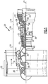
- FIG. 1 schematically illustrates an example gas turbine engine 20 that includes a fan section 22, a compressor section 24, a combustor section 26 and a turbine section 28.
- Alternative engines might include an augmenter section (not shown) among other systems or features.
- the fan section 22 drives air along a bypass flow path B while the compressor section 24 draws air in along a core flow path C where air is compressed and communicated to the combustor section 26.
- air is mixed with fuel and ignited to generate a high pressure exhaust gas stream that expands through the turbine section 28 where energy is extracted and utilized to drive the fan section 22 and the compressor section 24.
- turbofan gas turbine engine depicts a turbofan gas turbine engine
- concepts disclosed in this description and the accompanying drawings are not limited to use with turbofans as the teachings may be applied to other types of turbine engines, such as a turbine engine including a three-spool architecture in which three spools concentrically rotate about a common axis and where a low spool enables a low pressure turbine to drive a fan via a gearbox, an intermediate spool that enables an intermediate pressure turbine to drive a first compressor of the compressor section, and a high spool that enables a high pressure turbine to drive a high pressure compressor of the compressor section.
- the example engine 20 generally includes a low speed spool 30 and a high speed spool 32 mounted for rotation about an engine central longitudinal axis A relative to an engine static structure 36 via several bearing systems 38. It should be understood that various bearing systems 38 at various locations may alternatively or additionally be provided.
- the low speed spool 30 generally includes an inner shaft 40 that connects a fan 42 and a low pressure (or first) compressor section 44 to a low pressure (or first) turbine section 46.
- the inner shaft 40 drives the fan 42 through a speed change device, such as a geared architecture 48, to drive the fan 42 at a lower speed than the low speed spool 30.
- the high-speed spool 32 includes an outer shaft 50 that interconnects a high pressure (or second) compressor section 52 and a high pressure (or second) turbine section 54.
- the inner shaft 40 and the outer shaft 50 are concentric and rotate via the bearing systems 38 about the engine central longitudinal axis A.
- a combustor 56 is arranged between the high pressure compressor 52 and the high pressure turbine 54.
- the high pressure turbine 54 includes at least two stages to provide a double stage high pressure turbine 54.
- the high pressure turbine 54 includes only a single stage. As used in this description, a "high pressure" compressor or turbine experiences a higher pressure than a corresponding "low pressure” compressor or turbine.
- the example low pressure turbine 46 has a pressure ratio that is greater than about 5.
- the pressure ratio of the example low pressure turbine 46 is measured prior to an inlet of the low pressure turbine 46 as related to the pressure measured at the outlet of the low pressure turbine 46 prior to an exhaust nozzle.
- a mid-turbine frame 58 of the engine static structure 36 is arranged generally between the high pressure turbine 54 and the low pressure turbine 46.
- the mid-turbine frame 58 further supports bearing systems 38 in the turbine section 28 and sets airflow entering the low pressure turbine 46.
- the core airflow C is compressed by the low pressure compressor 44 then by the high pressure compressor 52 mixed with fuel and ignited in the combustor 56 to produce high speed exhaust gases that are then expanded through the high pressure turbine 54 and low pressure turbine 46.
- the mid-turbine frame 58 includes vanes 60, which are in the core airflow path and function as an inlet guide vane for the low pressure turbine 46. Utilizing the vane 60 of the mid-turbine frame 58 as the inlet guide vane for low pressure turbine 46 decreases the length of the low pressure turbine 46 without increasing the axial length of the mid-turbine frame 58. Reducing or eliminating the number of vanes in the low pressure turbine 46 shortens the axial length of the turbine section 28. Thus, the compactness of the gas turbine engine 20 is increased and a higher power density may be achieved.
- the gas turbine engine 20 is a high-bypass geared aircraft engine, including a bypass ratio greater than ten.
- the example geared architecture 48 is an epicyclical gear train, such as a planetary gear system, star gear system or other known gear system, with a gear reduction ratio of greater than about 2.3.
- the fan diameter is significantly larger than an outer diameter of the low pressure compressor 44.
- the fan section 22 of the engine 20 is designed for a particular flight condition -- typically cruise at about 0.8 Mach and about 35,000 feet (10,668 metres).
- the flight condition of 0.8 Mach and 35,000 ft. (10,668 m), with the engine at its best fuel consumption - also known as "bucket cruise Thrust Specific Fuel Consumption ('TSFC')" - is the industry standard parameter of pound-mass (lbm) of fuel per hour being burned divided by pound-force (lbf) of thrust the engine produces at that minimum point.
- Low fan pressure ratio is the pressure ratio across the fan blade alone, without a Fan Exit Guide Vane (“FEGV”) system.
- the low fan pressure ratio according to one non-limiting embodiment is less than about 1.50. In another non-limiting embodiment the low fan pressure ratio is less than about 1.45.
- the "Low corrected fan tip speed”, according to one non-limiting embodiment, is less than about 1150 ft/second (350.5 m/second).
- the example gas turbine engine includes the fan 42 that comprises in one non-limiting embodiment less than about 26 fan blades. In another non-limiting embodiment, the fan section 22 includes less than about 20 fan blades. Moreover, in one disclosed embodiment the low pressure turbine 46 includes no more than about 6 turbine rotors schematically indicated at 34. In another non-limiting example embodiment the low pressure turbine 46 includes about 3 turbine rotors. A ratio between the number of fan blades 42 and the number of low pressure turbine rotors is between about 3.3 and about 8.6. The example low pressure turbine 46 provides the driving power to rotate the fan section 22 and therefore the relationship between the number of turbine rotors 34 in the low pressure turbine 46 and the number of blades 42 in the fan section 22 disclose an example gas turbine engine 20 with increased power transfer efficiency.
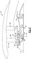
- Figure 2 illustrates selected portions of a gas turbine engine 20 including a fan section 22 that has more than one set of fan blades.
- a first plurality of fan blades 100 are supported on a first fan support 102 that is situated within the engine 20 for rotation about the axis A, which is referred to as the fan axis A for purposes of discussion.
- the first fan support 102 comprises a ring-like structure that is centered about the fan axis A.
- the example fan 42 includes a second plurality of fan blades 104 supported on a second fan support 106.
- the second plurality of fan blades 104 and the second fan support 106 which comprises a ring-like structure, are situated within the engine 20 for rotation about the fan axis A.
- the first fan support 102 and the second fan support 106 may rotate independently of each other.
- the first fan support 102 and the second fan support 106 are situated for rotating in opposite directions such that the fan 22 is a counter rotating fan.
- the geared architecture 48 is configured to cause rotation of the first fan support 102 in a first direction and the second fan support 106 in a second, opposite direction.
- the illustrated geared architecture 48 includes a first gear 110 that interacts with the first fan support 102 and the second fan support 106 through intermeshing gear teeth in one example.
- the first gear 110 rotates about a gear axis G, which is transverse to the fan axis A, the fan supports 102 and 106 rotate in opposite directions.
- the first gear 110 is coupled with a gear shaft 112 near one end of the gear shaft 112.
- the gear shaft 112 has a length that is situated along the gear axis G.
- a second gear 114 is situated near an opposite end of the gear shaft 112. The first gear 110, gear shaft 112 and second gear 114 all rotate in unison.
- the illustrated example includes a geared component 120 associated with the low spool 30 such that the geared component 120 rotates about the fan axis A.
- Rotation of the geared component 120 causes rotation of the second gear 114, which interacts with the geared component 120 through intermeshing gear teeth in one example.
- the gear shaft 112 and the first gear 110 rotate with the second gear 114.
- rotation of the low spool 30 about the fan axis A causes rotation of the geared architecture 48 about the gear axis G to cause counter rotation of the first plurality of fan blades 100 and the second plurality of fan blades 104 about the fan axis A.
- the gears 110 and 114 can be sized to achieve a desired speed reduction between the rotation of the fan blades 100, 104 and the turbine section or low spool 30.
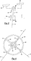
- the gear axis G is approximately perpendicular to the fan axis A.
- An offset of several degrees from perpendicular is utilized in some embodiments to accommodate the shape of the gears 110 and 114.
- the first gear 110 comprises a bevel gear and the second gear 114 comprises a bevel gear.
- gears rotate about the gear axis G, which is transverse to the fan axis A. At least the gear shaft 112 is situated in a generally radial direction relative to the fan axis A.
- Figure 4 illustrates an example arrangement of a geared architecture 48.
- This example includes a plurality of first gears 110, a plurality of gear shafts 112 and a corresponding plurality of second gears 114.
- the first gears 110 are circumferentially and equally spaced from each other about the axis A.
- Figure 4 shows the radial alignment of the gear shafts 112 relative to the fan axis A.
- the geared architecture 48 is situated in a spacing between a first compressor 44 and a second compressor 52 of the compressor section 24. In this example, the entire geared architecture 48 is situated within the spacing between the compressors 44 and 52.
- the radially-oriented geared architecture 48 allows for more flexibility in the placement of the geared architecture 48 within a gas turbine engine. This flexibility allows for more potential space savings within a gas turbine engine, especially in the axial direction.
Claims (9)
- Gasturbinenmotor (20), umfassend:einen Bläser (42), der Folgendes beinhaltet:eine erste Vielzahl von Bläserflügeln (100), die auf einem ersten Bläserträger (102) gehalten werden, der um eine Bläserachse (A) drehbar ist, undeine zweite Vielzahl von Bläserflügeln (104), die auf einem zweiten Bläserträger (106) gehalten werden, der um die Bläserachse (A) unabhängig von der ersten Vielzahl von Bläserflügeln (100) drehbar ist;einen Verdichterabschnitt (24), der einen ersten Verdichter (44) und einen zweiten Verdichter (52) umfasst,wobei der erste Verdichter (44) einem niedrigeren Druck ausgesetzt ist, als der zweite Verdichter (52) und ein Abstand zwischen dem ersten Verdichter (44) und dem zweiten Verdichter (52) in einer parallel zu der Bläserachse (A) verlaufenden Richtung besteht;eine Brennkammer (56) in Fluidverbindung mit dem Verdichterabschnitt (24); undeinen Turbinenabschnitt (28) in Fluidverbindung mit der Brennkammer (56); wobeider Motor (20) ein Nebenstromverhältnis größer als 10:1 beinhaltet;dadurch gekennzeichnet, dass:der Motor Folgendes beinhalteteine Getriebearchitektur (48), die mindestens ein Zahnrad (110, 114) beinhaltet, das dazu ausgelegt ist, von dem Turbinenabschnitt (28) angetrieben zu werden, um sich um eine Zahnradachse (G) zu drehen, die quer zur Bläserachse (A) verläuft, wobei das mindestens eine Zahnrad (110, 114) dazu ausgelegt ist, den ersten Bläserträger (102) anzutreiben, um die erste Vielzahl von Bläserflügeln (100) in einer ersten Richtung zu drehen, wobei das mindestens eine Zahnrad (110, 114) dazu ausgelegt ist, den zweiten Bläserträger (106) anzutreiben, um die zweite Vielzahl von Bläserflügeln (104) in einer zweiten Richtung, die entgegengesetzt zu der ersten Richtung verläuft, zu drehen,wobei die Getriebearchitektur (48) mindestens teilweise in dem Abstand angeordnet ist.
- Gasturbinenmotor (20) nach Anspruch 1, wobei das mindestens eine Zahnrad (110, 114) ein Kegelrad umfasst.
- Gasturbinenmotor (20) nach Anspruch 1 oder 2, wobei das mindestens eine Zahnrad Folgendes umfasst:ein erstes Zahnrad (110), das angeordnet ist, um mit dem ersten und zweiten Bläserträger (102, 106) zu interagieren,wobei sich das erste Zahnrad (110) um die Zahnradachse (G) dreht;ein zweites Zahnrad (114), das von dem ersten Zahnrad (110) beabstandet ist und angeordnet ist, um mit dem Turbinenabschnitt (28) zu interagieren, wobei sich das zweite Zahnrad (114) um die Zahnradachse (G) dreht; undeine Zahnradwelle (112), die an der Zahnradachse (G) ausgerichtet ist, wobei das erste Zahnrad (110) mit der Zahnradwelle (112) in der Nähe eines ersten Endes der Zahnradwelle (112) gekoppelt ist und das zweite Zahnrad (114) in der Nähe eines zweiten gegenüberliegenden Endes der Zahnradwelle (112) mit der Zahnradwelle (112) gekoppelt ist, derart dass das erste und zweite Zahnrad (110, 114) und die Zahnradwelle sich zusammen drehen.
- Gasturbinenmotor (20) nach Anspruch 3, wobei
der Motor (20) eine Getriebekomponente umfasst, die um die Bläserachse (A) drehbar ist; und
das erste Zahnrad (110) als Reaktion auf die Drehung der Getriebekomponente um die Zahnradachse (G) drehbar ist. - Gasturbinenmotor (20) nach Anspruch 4, wobei die Getriebekomponente mit einer Niederdruckwelle (30) verbunden ist, die mit dem Turbinenabschnitt (28) drehbar ist.
- Gasturbinenmotor (20) nach Anspruch 3, 4 oder 5, umfassend:eine Vielzahl der ersten Zahnräder (110);eine entsprechende Vielzahl der zweiten Zahnräder (114); undeine entsprechende Vielzahl von Zahnradwellen (112), wobei die Vielzahl von ersten Zahnrädern (110) in Umfangsrichtung um die Bläserachse (A) voneinander beabstandet sind.
- Gasturbinenmotor (20) nach einem der Ansprüche 3 bis 6, wobei das erste und zweite Zahnrad (110, 114) jeweils ein Kegelrad umfassen.
- Gasturbinenmotor (20) nach einem der vorhergehenden Ansprüche, wobei die Getriebearchitektur (48) mindestens eine Zahnradkomponente umfasst, die eine Länge aufweist, die sich entlang der Zahnradachse (G) in einer radialen Richtung in Bezug auf die Bläserachse (A) erstreckt.
- Gasturbinenmotor (20) nach einem der vorhergehenden Ansprüche, wobei
der erste Bläserträger (102) einen ersten Ring umfasst, der mindestens eine Fläche aufweist, die dazu ausgelegt ist, mit dem mindestens einen Zahnrad (110, 114) zum Drehen des ersten Bläserträgers (102) als Reaktion auf das Drehen des mindestens einen Zahnrads (110, 114) zu interagieren; und
der zweite Bläserträger (104) einen zweiten Ring umfasst, der mindestens eine Fläche aufweist, die dazu ausgelegt ist mit dem mindestens einen Zahnrad (110, 114) zum Drehen des zweiten Bläserträgers (104) als Reaktion auf das Drehen des mindestens einen Zahnrads (110, 114) zu interagieren.
Priority Applications (1)
| Application Number | Priority Date | Filing Date | Title |
|---|---|---|---|
| EP19193901.6A EP3594472A1 (de) | 2012-05-31 | 2013-05-23 | Gasturbinenmotor mit gegensinnig drehendem lüfter |
Applications Claiming Priority (2)
| Application Number | Priority Date | Filing Date | Title |
|---|---|---|---|
| US13/485,035 US20130318999A1 (en) | 2012-05-31 | 2012-05-31 | Gas turbine engine with a counter rotating fan |
| PCT/US2013/042357 WO2014031197A2 (en) | 2012-05-31 | 2013-05-23 | Gas turbine engine with a counter rotating fan |
Related Child Applications (1)
| Application Number | Title | Priority Date | Filing Date |
|---|---|---|---|
| EP19193901.6A Division EP3594472A1 (de) | 2012-05-31 | 2013-05-23 | Gasturbinenmotor mit gegensinnig drehendem lüfter |
Publications (3)
| Publication Number | Publication Date |
|---|---|
| EP2855874A2 EP2855874A2 (de) | 2015-04-08 |
| EP2855874A4 EP2855874A4 (de) | 2016-02-17 |
| EP2855874B1 true EP2855874B1 (de) | 2019-08-28 |
Family
ID=49668598
Family Applications (2)
| Application Number | Title | Priority Date | Filing Date |
|---|---|---|---|
| EP19193901.6A Withdrawn EP3594472A1 (de) | 2012-05-31 | 2013-05-23 | Gasturbinenmotor mit gegensinnig drehendem lüfter |
| EP13830416.7A Active EP2855874B1 (de) | 2012-05-31 | 2013-05-23 | Gasturbinenmotor mit gegenläufig drehendem bläser |
Family Applications Before (1)
| Application Number | Title | Priority Date | Filing Date |
|---|---|---|---|
| EP19193901.6A Withdrawn EP3594472A1 (de) | 2012-05-31 | 2013-05-23 | Gasturbinenmotor mit gegensinnig drehendem lüfter |
Country Status (3)
| Country | Link |
|---|---|
| US (1) | US20130318999A1 (de) |
| EP (2) | EP3594472A1 (de) |
| WO (1) | WO2014031197A2 (de) |
Families Citing this family (6)
| Publication number | Priority date | Publication date | Assignee | Title |
|---|---|---|---|---|
| US10393139B2 (en) | 2014-02-19 | 2019-08-27 | United Technologies Corporation | Gas turbine engine airfoil |
| US10669946B2 (en) * | 2015-06-05 | 2020-06-02 | Raytheon Technologies Corporation | Geared architecture for a gas turbine engine |
| US10669948B2 (en) * | 2017-01-03 | 2020-06-02 | Raytheon Technologies Corporation | Geared turbofan with non-epicyclic gear reduction system |
| US10358981B2 (en) * | 2017-04-11 | 2019-07-23 | United Technologies Corporation | High and low spool accessory gearbox drive |
| US10738694B1 (en) * | 2018-08-23 | 2020-08-11 | United Technologies Corporation | Turbofan with motorized rotating inlet guide vane |
| FR3138926A1 (fr) * | 2022-04-21 | 2024-02-23 | Franck GROLLEAU | Module de soufflantes contrarotatives à réducteur radial haute densité de puissance pour turbosoufflante |
Citations (1)
| Publication number | Priority date | Publication date | Assignee | Title |
|---|---|---|---|---|
| EP1340903A2 (de) * | 2002-03-01 | 2003-09-03 | General Electric Company | Gegenläufiges Bläsertriebwerk |
Family Cites Families (20)
| Publication number | Priority date | Publication date | Assignee | Title |
|---|---|---|---|---|
| US1902374A (en) * | 1931-05-15 | 1933-03-21 | Fiat Spa | Reducing gear |
| US2540991A (en) * | 1942-03-06 | 1951-02-06 | Lockheed Aircraft Corp | Gas reaction aircraft power plant |
| US2501633A (en) * | 1943-06-28 | 1950-03-21 | Lockheed Aircraft Corp | Gas turbine aircraft power plant having ducted propulsive compressor means |
| US2613749A (en) * | 1948-08-14 | 1952-10-14 | Lockheed Aircraft Corp | Gas turbine power plant having propeller drive |
| US2663517A (en) * | 1949-10-11 | 1953-12-22 | Lockheed Aircraft Corp | Aircraft power plant installation |
| US2780424A (en) * | 1951-10-19 | 1957-02-05 | Lockheed Aircraft Corp | Airplane for vertical take-off in horizontal attitude |
| US3688505A (en) * | 1969-10-13 | 1972-09-05 | Gen Motors Corp | Ducted fan engine |
| US3611834A (en) * | 1969-10-13 | 1971-10-12 | Gen Motors Corp | Fan drive |
| US3669564A (en) * | 1970-03-26 | 1972-06-13 | Heli Corp | Coaxial helicopter rotor system and transmission therefor |
| US4159624A (en) * | 1978-02-06 | 1979-07-03 | Gruner George P | Contra-rotating rotors with differential gearing |
| GB2195712B (en) * | 1986-10-08 | 1990-08-29 | Rolls Royce Plc | A turbofan gas turbine engine |
| GB8630754D0 (en) * | 1986-12-23 | 1987-02-04 | Rolls Royce Plc | Turbofan gas turbine engine |
| DE3812027A1 (de) * | 1988-04-11 | 1989-10-26 | Mtu Muenchen Gmbh | Propfan-turbotriebwerk |
| US4915586A (en) * | 1988-09-20 | 1990-04-10 | General Motors Corporation | Propfan blade attachment |
| US4936748A (en) * | 1988-11-28 | 1990-06-26 | General Electric Company | Auxiliary power source in an unducted fan gas turbine engine |
| US5575147A (en) * | 1994-12-22 | 1996-11-19 | United Technologies Corporation | Compact thrust reverser |
| US7540450B2 (en) * | 2004-07-16 | 2009-06-02 | Pratt & Whitney Canada Corp. | Aircraft propulsion system |
| US7752836B2 (en) * | 2005-10-19 | 2010-07-13 | General Electric Company | Gas turbine assembly and methods of assembling same |
| US20080016880A1 (en) * | 2006-07-24 | 2008-01-24 | Vittorio Bruno | Gas turbine starter gear shaft and method of manufacture |
| US20080056897A1 (en) * | 2006-09-06 | 2008-03-06 | Thomas Anderson | Counter rotating rotor head |
-
2012
- 2012-05-31 US US13/485,035 patent/US20130318999A1/en not_active Abandoned
-
2013
- 2013-05-23 EP EP19193901.6A patent/EP3594472A1/de not_active Withdrawn
- 2013-05-23 WO PCT/US2013/042357 patent/WO2014031197A2/en active Application Filing
- 2013-05-23 EP EP13830416.7A patent/EP2855874B1/de active Active
Patent Citations (1)
| Publication number | Priority date | Publication date | Assignee | Title |
|---|---|---|---|---|
| EP1340903A2 (de) * | 2002-03-01 | 2003-09-03 | General Electric Company | Gegenläufiges Bläsertriebwerk |
Non-Patent Citations (1)
| Title |
|---|
| PEIDER TRIPPI: "Propfan/UDF - Die neue Triebwerkgeneration auf dem Prüfstand", 15 November 1989 (1989-11-15), XP055363050, Retrieved from the Internet <URL:https://www.trippi-services.ch/app/download/8878347484/STZ_Nov1989.pdf?t=1477244255> [retrieved on 20170407] * |
Also Published As
| Publication number | Publication date |
|---|---|
| WO2014031197A3 (en) | 2014-05-30 |
| US20130318999A1 (en) | 2013-12-05 |
| WO2014031197A2 (en) | 2014-02-27 |
| EP2855874A2 (de) | 2015-04-08 |
| EP2855874A4 (de) | 2016-02-17 |
| EP3594472A1 (de) | 2020-01-15 |
Similar Documents
| Publication | Publication Date | Title |
|---|---|---|
| EP3101258B1 (de) | Getriebearchitektur für einen gasturbinenmotor sowie dazugehöriges verfahren | |
| EP2820267B1 (de) | Gegenläufiger niederdruckverdichter und turbine, beide mit einem getriebesystem | |
| EP2877725B1 (de) | Getriebefan mit innerem gegenläufig rotierendem verdichter | |
| EP3036416B1 (de) | Getriebefan mit hohem schub | |
| EP2820282B1 (de) | Gegenläufige niederdruckturbine mit einem an den mittelturbinenrahmen montierten getriebesystem | |
| EP2820265B1 (de) | Gegenläufige niederdruckturbine mit splittergetriebesystem | |
| US10190497B2 (en) | Counter-rotating low pressure turbine without turbine exhaust case | |
| EP3808964B1 (de) | Getriebefan mit einem nicht epizyklischen untersetzungssystem | |
| EP2971673B1 (de) | Druckbeaufschlagung des turbinenrades eines gasturbinenmotors | |
| US20210010426A1 (en) | Gear reduction for lower thrust geared turbofan | |
| US20200362765A1 (en) | Geared gas turbine engine | |
| EP3054138B1 (de) | Turboverdichter mit getriebefan | |
| EP2904233A1 (de) | Gasturbinenmotor mit grossem leichtgewichtigen lüfter | |
| EP2935787A2 (de) | Leichtgewichtige lüfterklinge mit einer ummantelung | |
| US9267389B2 (en) | Geared architecture carrier torque frame assembly | |
| EP2855874B1 (de) | Gasturbinenmotor mit gegenläufig drehendem bläser | |
| US20230167752A1 (en) | Gas turbine engine with high speed low pressure turbine section and bearing support features | |
| EP3019728B1 (de) | Dreiwelliger getriebefan mit niederdruckverdichterantriebssystem | |
| EP2935804B1 (de) | Gasturbinenmotor-innengehäuse mit unsymmetrischen entlüftungsschlitzen | |
| US10119400B2 (en) | High pressure rotor disk | |
| WO2014099713A1 (en) | Lightweight shrouded fan | |
| EP2900980A2 (de) | Geometrie zur integration einer primären und sekundären düse eines getriebeturbolüfters | |
| EP3611359B1 (de) | Verzahnungsring für einen flexiblen träger eines bläserantriebs |
Legal Events
| Date | Code | Title | Description |
|---|---|---|---|
| PUAI | Public reference made under article 153(3) epc to a published international application that has entered the european phase |
Free format text: ORIGINAL CODE: 0009012 |
|
| 17P | Request for examination filed |
Effective date: 20141111 |
|
| AK | Designated contracting states |
Kind code of ref document: A2 Designated state(s): AL AT BE BG CH CY CZ DE DK EE ES FI FR GB GR HR HU IE IS IT LI LT LU LV MC MK MT NL NO PL PT RO RS SE SI SK SM TR |
|
| AX | Request for extension of the european patent |
Extension state: BA ME |
|
| DAX | Request for extension of the european patent (deleted) | ||
| A4 | Supplementary search report drawn up and despatched |
Effective date: 20160115 |
|
| RIC1 | Information provided on ipc code assigned before grant |
Ipc: F02C 7/36 20060101ALI20160111BHEP Ipc: F02K 3/072 20060101ALI20160111BHEP Ipc: F02C 3/067 20060101AFI20160111BHEP Ipc: F02C 3/107 20060101ALI20160111BHEP |
|
| RAP1 | Party data changed (applicant data changed or rights of an application transferred) |
Owner name: UNITED TECHNOLOGIES CORPORATION |
|
| STAA | Information on the status of an ep patent application or granted ep patent |
Free format text: STATUS: EXAMINATION IS IN PROGRESS |
|
| 17Q | First examination report despatched |
Effective date: 20170418 |
|
| GRAP | Despatch of communication of intention to grant a patent |
Free format text: ORIGINAL CODE: EPIDOSNIGR1 |
|
| STAA | Information on the status of an ep patent application or granted ep patent |
Free format text: STATUS: GRANT OF PATENT IS INTENDED |
|
| INTG | Intention to grant announced |
Effective date: 20190308 |
|
| GRAS | Grant fee paid |
Free format text: ORIGINAL CODE: EPIDOSNIGR3 |
|
| GRAA | (expected) grant |
Free format text: ORIGINAL CODE: 0009210 |
|
| STAA | Information on the status of an ep patent application or granted ep patent |
Free format text: STATUS: THE PATENT HAS BEEN GRANTED |
|
| AK | Designated contracting states |
Kind code of ref document: B1 Designated state(s): AL AT BE BG CH CY CZ DE DK EE ES FI FR GB GR HR HU IE IS IT LI LT LU LV MC MK MT NL NO PL PT RO RS SE SI SK SM TR |
|
| REG | Reference to a national code |
Ref country code: GB Ref legal event code: FG4D |
|
| REG | Reference to a national code |
Ref country code: CH Ref legal event code: EP |
|
| REG | Reference to a national code |
Ref country code: AT Ref legal event code: REF Ref document number: 1172689 Country of ref document: AT Kind code of ref document: T Effective date: 20190915 |
|
| REG | Reference to a national code |
Ref country code: IE Ref legal event code: FG4D |
|
| REG | Reference to a national code |
Ref country code: DE Ref legal event code: R096 Ref document number: 602013059830 Country of ref document: DE |
|
| REG | Reference to a national code |
Ref country code: NL Ref legal event code: MP Effective date: 20190828 |
|
| REG | Reference to a national code |
Ref country code: LT Ref legal event code: MG4D |
|
| PG25 | Lapsed in a contracting state [announced via postgrant information from national office to epo] |
Ref country code: FI Free format text: LAPSE BECAUSE OF FAILURE TO SUBMIT A TRANSLATION OF THE DESCRIPTION OR TO PAY THE FEE WITHIN THE PRESCRIBED TIME-LIMIT Effective date: 20190828 Ref country code: NL Free format text: LAPSE BECAUSE OF FAILURE TO SUBMIT A TRANSLATION OF THE DESCRIPTION OR TO PAY THE FEE WITHIN THE PRESCRIBED TIME-LIMIT Effective date: 20190828 Ref country code: LT Free format text: LAPSE BECAUSE OF FAILURE TO SUBMIT A TRANSLATION OF THE DESCRIPTION OR TO PAY THE FEE WITHIN THE PRESCRIBED TIME-LIMIT Effective date: 20190828 Ref country code: HR Free format text: LAPSE BECAUSE OF FAILURE TO SUBMIT A TRANSLATION OF THE DESCRIPTION OR TO PAY THE FEE WITHIN THE PRESCRIBED TIME-LIMIT Effective date: 20190828 Ref country code: BG Free format text: LAPSE BECAUSE OF FAILURE TO SUBMIT A TRANSLATION OF THE DESCRIPTION OR TO PAY THE FEE WITHIN THE PRESCRIBED TIME-LIMIT Effective date: 20191128 Ref country code: SE Free format text: LAPSE BECAUSE OF FAILURE TO SUBMIT A TRANSLATION OF THE DESCRIPTION OR TO PAY THE FEE WITHIN THE PRESCRIBED TIME-LIMIT Effective date: 20190828 Ref country code: PT Free format text: LAPSE BECAUSE OF FAILURE TO SUBMIT A TRANSLATION OF THE DESCRIPTION OR TO PAY THE FEE WITHIN THE PRESCRIBED TIME-LIMIT Effective date: 20191230 Ref country code: NO Free format text: LAPSE BECAUSE OF FAILURE TO SUBMIT A TRANSLATION OF THE DESCRIPTION OR TO PAY THE FEE WITHIN THE PRESCRIBED TIME-LIMIT Effective date: 20191128 |
|
| PG25 | Lapsed in a contracting state [announced via postgrant information from national office to epo] |
Ref country code: IS Free format text: LAPSE BECAUSE OF FAILURE TO SUBMIT A TRANSLATION OF THE DESCRIPTION OR TO PAY THE FEE WITHIN THE PRESCRIBED TIME-LIMIT Effective date: 20191228 Ref country code: ES Free format text: LAPSE BECAUSE OF FAILURE TO SUBMIT A TRANSLATION OF THE DESCRIPTION OR TO PAY THE FEE WITHIN THE PRESCRIBED TIME-LIMIT Effective date: 20190828 Ref country code: GR Free format text: LAPSE BECAUSE OF FAILURE TO SUBMIT A TRANSLATION OF THE DESCRIPTION OR TO PAY THE FEE WITHIN THE PRESCRIBED TIME-LIMIT Effective date: 20191129 Ref country code: RS Free format text: LAPSE BECAUSE OF FAILURE TO SUBMIT A TRANSLATION OF THE DESCRIPTION OR TO PAY THE FEE WITHIN THE PRESCRIBED TIME-LIMIT Effective date: 20190828 Ref country code: LV Free format text: LAPSE BECAUSE OF FAILURE TO SUBMIT A TRANSLATION OF THE DESCRIPTION OR TO PAY THE FEE WITHIN THE PRESCRIBED TIME-LIMIT Effective date: 20190828 Ref country code: AL Free format text: LAPSE BECAUSE OF FAILURE TO SUBMIT A TRANSLATION OF THE DESCRIPTION OR TO PAY THE FEE WITHIN THE PRESCRIBED TIME-LIMIT Effective date: 20190828 |
|
| REG | Reference to a national code |
Ref country code: AT Ref legal event code: MK05 Ref document number: 1172689 Country of ref document: AT Kind code of ref document: T Effective date: 20190828 |
|
| PG25 | Lapsed in a contracting state [announced via postgrant information from national office to epo] |
Ref country code: TR Free format text: LAPSE BECAUSE OF FAILURE TO SUBMIT A TRANSLATION OF THE DESCRIPTION OR TO PAY THE FEE WITHIN THE PRESCRIBED TIME-LIMIT Effective date: 20190828 |
|
| PG25 | Lapsed in a contracting state [announced via postgrant information from national office to epo] |
Ref country code: EE Free format text: LAPSE BECAUSE OF FAILURE TO SUBMIT A TRANSLATION OF THE DESCRIPTION OR TO PAY THE FEE WITHIN THE PRESCRIBED TIME-LIMIT Effective date: 20190828 Ref country code: PL Free format text: LAPSE BECAUSE OF FAILURE TO SUBMIT A TRANSLATION OF THE DESCRIPTION OR TO PAY THE FEE WITHIN THE PRESCRIBED TIME-LIMIT Effective date: 20190828 Ref country code: DK Free format text: LAPSE BECAUSE OF FAILURE TO SUBMIT A TRANSLATION OF THE DESCRIPTION OR TO PAY THE FEE WITHIN THE PRESCRIBED TIME-LIMIT Effective date: 20190828 Ref country code: IT Free format text: LAPSE BECAUSE OF FAILURE TO SUBMIT A TRANSLATION OF THE DESCRIPTION OR TO PAY THE FEE WITHIN THE PRESCRIBED TIME-LIMIT Effective date: 20190828 Ref country code: RO Free format text: LAPSE BECAUSE OF FAILURE TO SUBMIT A TRANSLATION OF THE DESCRIPTION OR TO PAY THE FEE WITHIN THE PRESCRIBED TIME-LIMIT Effective date: 20190828 Ref country code: AT Free format text: LAPSE BECAUSE OF FAILURE TO SUBMIT A TRANSLATION OF THE DESCRIPTION OR TO PAY THE FEE WITHIN THE PRESCRIBED TIME-LIMIT Effective date: 20190828 |
|
| PG25 | Lapsed in a contracting state [announced via postgrant information from national office to epo] |
Ref country code: SM Free format text: LAPSE BECAUSE OF FAILURE TO SUBMIT A TRANSLATION OF THE DESCRIPTION OR TO PAY THE FEE WITHIN THE PRESCRIBED TIME-LIMIT Effective date: 20190828 Ref country code: IS Free format text: LAPSE BECAUSE OF FAILURE TO SUBMIT A TRANSLATION OF THE DESCRIPTION OR TO PAY THE FEE WITHIN THE PRESCRIBED TIME-LIMIT Effective date: 20200224 Ref country code: SK Free format text: LAPSE BECAUSE OF FAILURE TO SUBMIT A TRANSLATION OF THE DESCRIPTION OR TO PAY THE FEE WITHIN THE PRESCRIBED TIME-LIMIT Effective date: 20190828 Ref country code: CZ Free format text: LAPSE BECAUSE OF FAILURE TO SUBMIT A TRANSLATION OF THE DESCRIPTION OR TO PAY THE FEE WITHIN THE PRESCRIBED TIME-LIMIT Effective date: 20190828 |
|
| REG | Reference to a national code |
Ref country code: DE Ref legal event code: R097 Ref document number: 602013059830 Country of ref document: DE |
|
| PLBE | No opposition filed within time limit |
Free format text: ORIGINAL CODE: 0009261 |
|
| STAA | Information on the status of an ep patent application or granted ep patent |
Free format text: STATUS: NO OPPOSITION FILED WITHIN TIME LIMIT |
|
| PG2D | Information on lapse in contracting state deleted |
Ref country code: IS |
|
| 26N | No opposition filed |
Effective date: 20200603 |
|
| PG25 | Lapsed in a contracting state [announced via postgrant information from national office to epo] |
Ref country code: SI Free format text: LAPSE BECAUSE OF FAILURE TO SUBMIT A TRANSLATION OF THE DESCRIPTION OR TO PAY THE FEE WITHIN THE PRESCRIBED TIME-LIMIT Effective date: 20190828 |
|
| PG25 | Lapsed in a contracting state [announced via postgrant information from national office to epo] |
Ref country code: LI Free format text: LAPSE BECAUSE OF NON-PAYMENT OF DUE FEES Effective date: 20200531 Ref country code: CH Free format text: LAPSE BECAUSE OF NON-PAYMENT OF DUE FEES Effective date: 20200531 Ref country code: MC Free format text: LAPSE BECAUSE OF FAILURE TO SUBMIT A TRANSLATION OF THE DESCRIPTION OR TO PAY THE FEE WITHIN THE PRESCRIBED TIME-LIMIT Effective date: 20190828 |
|
| REG | Reference to a national code |
Ref country code: BE Ref legal event code: MM Effective date: 20200531 |
|
| PG25 | Lapsed in a contracting state [announced via postgrant information from national office to epo] |
Ref country code: LU Free format text: LAPSE BECAUSE OF NON-PAYMENT OF DUE FEES Effective date: 20200523 |
|
| PG25 | Lapsed in a contracting state [announced via postgrant information from national office to epo] |
Ref country code: IE Free format text: LAPSE BECAUSE OF NON-PAYMENT OF DUE FEES Effective date: 20200523 |
|
| PG25 | Lapsed in a contracting state [announced via postgrant information from national office to epo] |
Ref country code: BE Free format text: LAPSE BECAUSE OF NON-PAYMENT OF DUE FEES Effective date: 20200531 |
|
| PG25 | Lapsed in a contracting state [announced via postgrant information from national office to epo] |
Ref country code: MT Free format text: LAPSE BECAUSE OF FAILURE TO SUBMIT A TRANSLATION OF THE DESCRIPTION OR TO PAY THE FEE WITHIN THE PRESCRIBED TIME-LIMIT Effective date: 20190828 Ref country code: CY Free format text: LAPSE BECAUSE OF FAILURE TO SUBMIT A TRANSLATION OF THE DESCRIPTION OR TO PAY THE FEE WITHIN THE PRESCRIBED TIME-LIMIT Effective date: 20190828 |
|
| PG25 | Lapsed in a contracting state [announced via postgrant information from national office to epo] |
Ref country code: MK Free format text: LAPSE BECAUSE OF FAILURE TO SUBMIT A TRANSLATION OF THE DESCRIPTION OR TO PAY THE FEE WITHIN THE PRESCRIBED TIME-LIMIT Effective date: 20190828 |
|
| REG | Reference to a national code |
Ref country code: DE Ref legal event code: R081 Ref document number: 602013059830 Country of ref document: DE Owner name: RAYTHEON TECHNOLOGIES CORPORATION (N.D.GES.D.S, US Free format text: FORMER OWNER: UNITED TECHNOLOGIES CORPORATION, FARMINGTON, CONN., US |
|
| P01 | Opt-out of the competence of the unified patent court (upc) registered |
Effective date: 20230520 |
|
| PGFP | Annual fee paid to national office [announced via postgrant information from national office to epo] |
Ref country code: FR Payment date: 20230420 Year of fee payment: 11 Ref country code: DE Payment date: 20230419 Year of fee payment: 11 |
|
| PGFP | Annual fee paid to national office [announced via postgrant information from national office to epo] |
Ref country code: GB Payment date: 20230420 Year of fee payment: 11 |