EP2855742B1 - Concentric flow reactor - Google Patents
Concentric flow reactor Download PDFInfo
- Publication number
- EP2855742B1 EP2855742B1 EP13726897.5A EP13726897A EP2855742B1 EP 2855742 B1 EP2855742 B1 EP 2855742B1 EP 13726897 A EP13726897 A EP 13726897A EP 2855742 B1 EP2855742 B1 EP 2855742B1
- Authority
- EP
- European Patent Office
- Prior art keywords
- gas
- input
- nanowires
- reactor
- reaction chamber
- Prior art date
- Legal status (The legal status is an assumption and is not a legal conclusion. Google has not performed a legal analysis and makes no representation as to the accuracy of the status listed.)
- Active
Links
Images




Classifications
-
- C—CHEMISTRY; METALLURGY
- C30—CRYSTAL GROWTH
- C30B—SINGLE-CRYSTAL GROWTH; UNIDIRECTIONAL SOLIDIFICATION OF EUTECTIC MATERIAL OR UNIDIRECTIONAL DEMIXING OF EUTECTOID MATERIAL; REFINING BY ZONE-MELTING OF MATERIAL; PRODUCTION OF A HOMOGENEOUS POLYCRYSTALLINE MATERIAL WITH DEFINED STRUCTURE; SINGLE CRYSTALS OR HOMOGENEOUS POLYCRYSTALLINE MATERIAL WITH DEFINED STRUCTURE; AFTER-TREATMENT OF SINGLE CRYSTALS OR A HOMOGENEOUS POLYCRYSTALLINE MATERIAL WITH DEFINED STRUCTURE; APPARATUS THEREFOR
- C30B25/00—Single-crystal growth by chemical reaction of reactive gases, e.g. chemical vapour-deposition growth
- C30B25/02—Epitaxial-layer growth
- C30B25/14—Feed and outlet means for the gases; Modifying the flow of the reactive gases
-
- C—CHEMISTRY; METALLURGY
- C30—CRYSTAL GROWTH
- C30B—SINGLE-CRYSTAL GROWTH; UNIDIRECTIONAL SOLIDIFICATION OF EUTECTIC MATERIAL OR UNIDIRECTIONAL DEMIXING OF EUTECTOID MATERIAL; REFINING BY ZONE-MELTING OF MATERIAL; PRODUCTION OF A HOMOGENEOUS POLYCRYSTALLINE MATERIAL WITH DEFINED STRUCTURE; SINGLE CRYSTALS OR HOMOGENEOUS POLYCRYSTALLINE MATERIAL WITH DEFINED STRUCTURE; AFTER-TREATMENT OF SINGLE CRYSTALS OR A HOMOGENEOUS POLYCRYSTALLINE MATERIAL WITH DEFINED STRUCTURE; APPARATUS THEREFOR
- C30B11/00—Single-crystal growth by normal freezing or freezing under temperature gradient, e.g. Bridgman-Stockbarger method
- C30B11/006—Controlling or regulating
-
- C—CHEMISTRY; METALLURGY
- C23—COATING METALLIC MATERIAL; COATING MATERIAL WITH METALLIC MATERIAL; CHEMICAL SURFACE TREATMENT; DIFFUSION TREATMENT OF METALLIC MATERIAL; COATING BY VACUUM EVAPORATION, BY SPUTTERING, BY ION IMPLANTATION OR BY CHEMICAL VAPOUR DEPOSITION, IN GENERAL; INHIBITING CORROSION OF METALLIC MATERIAL OR INCRUSTATION IN GENERAL
- C23C—COATING METALLIC MATERIAL; COATING MATERIAL WITH METALLIC MATERIAL; SURFACE TREATMENT OF METALLIC MATERIAL BY DIFFUSION INTO THE SURFACE, BY CHEMICAL CONVERSION OR SUBSTITUTION; COATING BY VACUUM EVAPORATION, BY SPUTTERING, BY ION IMPLANTATION OR BY CHEMICAL VAPOUR DEPOSITION, IN GENERAL
- C23C16/00—Chemical coating by decomposition of gaseous compounds, without leaving reaction products of surface material in the coating, i.e. chemical vapour deposition [CVD] processes
- C23C16/22—Chemical coating by decomposition of gaseous compounds, without leaving reaction products of surface material in the coating, i.e. chemical vapour deposition [CVD] processes characterised by the deposition of inorganic material, other than metallic material
- C23C16/30—Deposition of compounds, mixtures or solid solutions, e.g. borides, carbides, nitrides
- C23C16/301—AIII BV compounds, where A is Al, Ga, In or Tl and B is N, P, As, Sb or Bi
-
- C—CHEMISTRY; METALLURGY
- C23—COATING METALLIC MATERIAL; COATING MATERIAL WITH METALLIC MATERIAL; CHEMICAL SURFACE TREATMENT; DIFFUSION TREATMENT OF METALLIC MATERIAL; COATING BY VACUUM EVAPORATION, BY SPUTTERING, BY ION IMPLANTATION OR BY CHEMICAL VAPOUR DEPOSITION, IN GENERAL; INHIBITING CORROSION OF METALLIC MATERIAL OR INCRUSTATION IN GENERAL
- C23C—COATING METALLIC MATERIAL; COATING MATERIAL WITH METALLIC MATERIAL; SURFACE TREATMENT OF METALLIC MATERIAL BY DIFFUSION INTO THE SURFACE, BY CHEMICAL CONVERSION OR SUBSTITUTION; COATING BY VACUUM EVAPORATION, BY SPUTTERING, BY ION IMPLANTATION OR BY CHEMICAL VAPOUR DEPOSITION, IN GENERAL
- C23C16/00—Chemical coating by decomposition of gaseous compounds, without leaving reaction products of surface material in the coating, i.e. chemical vapour deposition [CVD] processes
- C23C16/44—Chemical coating by decomposition of gaseous compounds, without leaving reaction products of surface material in the coating, i.e. chemical vapour deposition [CVD] processes characterised by the method of coating
- C23C16/455—Chemical coating by decomposition of gaseous compounds, without leaving reaction products of surface material in the coating, i.e. chemical vapour deposition [CVD] processes characterised by the method of coating characterised by the method used for introducing gases into reaction chamber or for modifying gas flows in reaction chamber
- C23C16/45502—Flow conditions in reaction chamber
- C23C16/45504—Laminar flow
-
- C—CHEMISTRY; METALLURGY
- C23—COATING METALLIC MATERIAL; COATING MATERIAL WITH METALLIC MATERIAL; CHEMICAL SURFACE TREATMENT; DIFFUSION TREATMENT OF METALLIC MATERIAL; COATING BY VACUUM EVAPORATION, BY SPUTTERING, BY ION IMPLANTATION OR BY CHEMICAL VAPOUR DEPOSITION, IN GENERAL; INHIBITING CORROSION OF METALLIC MATERIAL OR INCRUSTATION IN GENERAL
- C23C—COATING METALLIC MATERIAL; COATING MATERIAL WITH METALLIC MATERIAL; SURFACE TREATMENT OF METALLIC MATERIAL BY DIFFUSION INTO THE SURFACE, BY CHEMICAL CONVERSION OR SUBSTITUTION; COATING BY VACUUM EVAPORATION, BY SPUTTERING, BY ION IMPLANTATION OR BY CHEMICAL VAPOUR DEPOSITION, IN GENERAL
- C23C16/00—Chemical coating by decomposition of gaseous compounds, without leaving reaction products of surface material in the coating, i.e. chemical vapour deposition [CVD] processes
- C23C16/44—Chemical coating by decomposition of gaseous compounds, without leaving reaction products of surface material in the coating, i.e. chemical vapour deposition [CVD] processes characterised by the method of coating
- C23C16/455—Chemical coating by decomposition of gaseous compounds, without leaving reaction products of surface material in the coating, i.e. chemical vapour deposition [CVD] processes characterised by the method of coating characterised by the method used for introducing gases into reaction chamber or for modifying gas flows in reaction chamber
- C23C16/45519—Inert gas curtains
-
- C—CHEMISTRY; METALLURGY
- C30—CRYSTAL GROWTH
- C30B—SINGLE-CRYSTAL GROWTH; UNIDIRECTIONAL SOLIDIFICATION OF EUTECTIC MATERIAL OR UNIDIRECTIONAL DEMIXING OF EUTECTOID MATERIAL; REFINING BY ZONE-MELTING OF MATERIAL; PRODUCTION OF A HOMOGENEOUS POLYCRYSTALLINE MATERIAL WITH DEFINED STRUCTURE; SINGLE CRYSTALS OR HOMOGENEOUS POLYCRYSTALLINE MATERIAL WITH DEFINED STRUCTURE; AFTER-TREATMENT OF SINGLE CRYSTALS OR A HOMOGENEOUS POLYCRYSTALLINE MATERIAL WITH DEFINED STRUCTURE; APPARATUS THEREFOR
- C30B11/00—Single-crystal growth by normal freezing or freezing under temperature gradient, e.g. Bridgman-Stockbarger method
- C30B11/003—Heating or cooling of the melt or the crystallised material
-
- C—CHEMISTRY; METALLURGY
- C30—CRYSTAL GROWTH
- C30B—SINGLE-CRYSTAL GROWTH; UNIDIRECTIONAL SOLIDIFICATION OF EUTECTIC MATERIAL OR UNIDIRECTIONAL DEMIXING OF EUTECTOID MATERIAL; REFINING BY ZONE-MELTING OF MATERIAL; PRODUCTION OF A HOMOGENEOUS POLYCRYSTALLINE MATERIAL WITH DEFINED STRUCTURE; SINGLE CRYSTALS OR HOMOGENEOUS POLYCRYSTALLINE MATERIAL WITH DEFINED STRUCTURE; AFTER-TREATMENT OF SINGLE CRYSTALS OR A HOMOGENEOUS POLYCRYSTALLINE MATERIAL WITH DEFINED STRUCTURE; APPARATUS THEREFOR
- C30B11/00—Single-crystal growth by normal freezing or freezing under temperature gradient, e.g. Bridgman-Stockbarger method
- C30B11/04—Single-crystal growth by normal freezing or freezing under temperature gradient, e.g. Bridgman-Stockbarger method adding crystallising materials or reactants forming it in situ to the melt
- C30B11/08—Single-crystal growth by normal freezing or freezing under temperature gradient, e.g. Bridgman-Stockbarger method adding crystallising materials or reactants forming it in situ to the melt every component of the crystal composition being added during the crystallisation
- C30B11/12—Vaporous components, e.g. vapour-liquid-solid-growth
-
- C—CHEMISTRY; METALLURGY
- C30—CRYSTAL GROWTH
- C30B—SINGLE-CRYSTAL GROWTH; UNIDIRECTIONAL SOLIDIFICATION OF EUTECTIC MATERIAL OR UNIDIRECTIONAL DEMIXING OF EUTECTOID MATERIAL; REFINING BY ZONE-MELTING OF MATERIAL; PRODUCTION OF A HOMOGENEOUS POLYCRYSTALLINE MATERIAL WITH DEFINED STRUCTURE; SINGLE CRYSTALS OR HOMOGENEOUS POLYCRYSTALLINE MATERIAL WITH DEFINED STRUCTURE; AFTER-TREATMENT OF SINGLE CRYSTALS OR A HOMOGENEOUS POLYCRYSTALLINE MATERIAL WITH DEFINED STRUCTURE; APPARATUS THEREFOR
- C30B23/00—Single-crystal growth by condensing evaporated or sublimed materials
- C30B23/007—Growth of whiskers or needles
-
- C—CHEMISTRY; METALLURGY
- C30—CRYSTAL GROWTH
- C30B—SINGLE-CRYSTAL GROWTH; UNIDIRECTIONAL SOLIDIFICATION OF EUTECTIC MATERIAL OR UNIDIRECTIONAL DEMIXING OF EUTECTOID MATERIAL; REFINING BY ZONE-MELTING OF MATERIAL; PRODUCTION OF A HOMOGENEOUS POLYCRYSTALLINE MATERIAL WITH DEFINED STRUCTURE; SINGLE CRYSTALS OR HOMOGENEOUS POLYCRYSTALLINE MATERIAL WITH DEFINED STRUCTURE; AFTER-TREATMENT OF SINGLE CRYSTALS OR A HOMOGENEOUS POLYCRYSTALLINE MATERIAL WITH DEFINED STRUCTURE; APPARATUS THEREFOR
- C30B25/00—Single-crystal growth by chemical reaction of reactive gases, e.g. chemical vapour-deposition growth
- C30B25/005—Growth of whiskers or needles
-
- C—CHEMISTRY; METALLURGY
- C30—CRYSTAL GROWTH
- C30B—SINGLE-CRYSTAL GROWTH; UNIDIRECTIONAL SOLIDIFICATION OF EUTECTIC MATERIAL OR UNIDIRECTIONAL DEMIXING OF EUTECTOID MATERIAL; REFINING BY ZONE-MELTING OF MATERIAL; PRODUCTION OF A HOMOGENEOUS POLYCRYSTALLINE MATERIAL WITH DEFINED STRUCTURE; SINGLE CRYSTALS OR HOMOGENEOUS POLYCRYSTALLINE MATERIAL WITH DEFINED STRUCTURE; AFTER-TREATMENT OF SINGLE CRYSTALS OR A HOMOGENEOUS POLYCRYSTALLINE MATERIAL WITH DEFINED STRUCTURE; APPARATUS THEREFOR
- C30B25/00—Single-crystal growth by chemical reaction of reactive gases, e.g. chemical vapour-deposition growth
- C30B25/02—Epitaxial-layer growth
- C30B25/025—Continuous growth
-
- C—CHEMISTRY; METALLURGY
- C30—CRYSTAL GROWTH
- C30B—SINGLE-CRYSTAL GROWTH; UNIDIRECTIONAL SOLIDIFICATION OF EUTECTIC MATERIAL OR UNIDIRECTIONAL DEMIXING OF EUTECTOID MATERIAL; REFINING BY ZONE-MELTING OF MATERIAL; PRODUCTION OF A HOMOGENEOUS POLYCRYSTALLINE MATERIAL WITH DEFINED STRUCTURE; SINGLE CRYSTALS OR HOMOGENEOUS POLYCRYSTALLINE MATERIAL WITH DEFINED STRUCTURE; AFTER-TREATMENT OF SINGLE CRYSTALS OR A HOMOGENEOUS POLYCRYSTALLINE MATERIAL WITH DEFINED STRUCTURE; APPARATUS THEREFOR
- C30B29/00—Single crystals or homogeneous polycrystalline material with defined structure characterised by the material or by their shape
- C30B29/02—Elements
- C30B29/06—Silicon
-
- C—CHEMISTRY; METALLURGY
- C30—CRYSTAL GROWTH
- C30B—SINGLE-CRYSTAL GROWTH; UNIDIRECTIONAL SOLIDIFICATION OF EUTECTIC MATERIAL OR UNIDIRECTIONAL DEMIXING OF EUTECTOID MATERIAL; REFINING BY ZONE-MELTING OF MATERIAL; PRODUCTION OF A HOMOGENEOUS POLYCRYSTALLINE MATERIAL WITH DEFINED STRUCTURE; SINGLE CRYSTALS OR HOMOGENEOUS POLYCRYSTALLINE MATERIAL WITH DEFINED STRUCTURE; AFTER-TREATMENT OF SINGLE CRYSTALS OR A HOMOGENEOUS POLYCRYSTALLINE MATERIAL WITH DEFINED STRUCTURE; APPARATUS THEREFOR
- C30B29/00—Single crystals or homogeneous polycrystalline material with defined structure characterised by the material or by their shape
- C30B29/10—Inorganic compounds or compositions
- C30B29/40—AIIIBV compounds wherein A is B, Al, Ga, In or Tl and B is N, P, As, Sb or Bi
-
- C—CHEMISTRY; METALLURGY
- C30—CRYSTAL GROWTH
- C30B—SINGLE-CRYSTAL GROWTH; UNIDIRECTIONAL SOLIDIFICATION OF EUTECTIC MATERIAL OR UNIDIRECTIONAL DEMIXING OF EUTECTOID MATERIAL; REFINING BY ZONE-MELTING OF MATERIAL; PRODUCTION OF A HOMOGENEOUS POLYCRYSTALLINE MATERIAL WITH DEFINED STRUCTURE; SINGLE CRYSTALS OR HOMOGENEOUS POLYCRYSTALLINE MATERIAL WITH DEFINED STRUCTURE; AFTER-TREATMENT OF SINGLE CRYSTALS OR A HOMOGENEOUS POLYCRYSTALLINE MATERIAL WITH DEFINED STRUCTURE; APPARATUS THEREFOR
- C30B29/00—Single crystals or homogeneous polycrystalline material with defined structure characterised by the material or by their shape
- C30B29/10—Inorganic compounds or compositions
- C30B29/40—AIIIBV compounds wherein A is B, Al, Ga, In or Tl and B is N, P, As, Sb or Bi
- C30B29/403—AIII-nitrides
-
- C—CHEMISTRY; METALLURGY
- C30—CRYSTAL GROWTH
- C30B—SINGLE-CRYSTAL GROWTH; UNIDIRECTIONAL SOLIDIFICATION OF EUTECTIC MATERIAL OR UNIDIRECTIONAL DEMIXING OF EUTECTOID MATERIAL; REFINING BY ZONE-MELTING OF MATERIAL; PRODUCTION OF A HOMOGENEOUS POLYCRYSTALLINE MATERIAL WITH DEFINED STRUCTURE; SINGLE CRYSTALS OR HOMOGENEOUS POLYCRYSTALLINE MATERIAL WITH DEFINED STRUCTURE; AFTER-TREATMENT OF SINGLE CRYSTALS OR A HOMOGENEOUS POLYCRYSTALLINE MATERIAL WITH DEFINED STRUCTURE; APPARATUS THEREFOR
- C30B29/00—Single crystals or homogeneous polycrystalline material with defined structure characterised by the material or by their shape
- C30B29/10—Inorganic compounds or compositions
- C30B29/40—AIIIBV compounds wherein A is B, Al, Ga, In or Tl and B is N, P, As, Sb or Bi
- C30B29/42—Gallium arsenide
-
- C—CHEMISTRY; METALLURGY
- C30—CRYSTAL GROWTH
- C30B—SINGLE-CRYSTAL GROWTH; UNIDIRECTIONAL SOLIDIFICATION OF EUTECTIC MATERIAL OR UNIDIRECTIONAL DEMIXING OF EUTECTOID MATERIAL; REFINING BY ZONE-MELTING OF MATERIAL; PRODUCTION OF A HOMOGENEOUS POLYCRYSTALLINE MATERIAL WITH DEFINED STRUCTURE; SINGLE CRYSTALS OR HOMOGENEOUS POLYCRYSTALLINE MATERIAL WITH DEFINED STRUCTURE; AFTER-TREATMENT OF SINGLE CRYSTALS OR A HOMOGENEOUS POLYCRYSTALLINE MATERIAL WITH DEFINED STRUCTURE; APPARATUS THEREFOR
- C30B29/00—Single crystals or homogeneous polycrystalline material with defined structure characterised by the material or by their shape
- C30B29/60—Single crystals or homogeneous polycrystalline material with defined structure characterised by the material or by their shape characterised by shape
-
- C—CHEMISTRY; METALLURGY
- C30—CRYSTAL GROWTH
- C30B—SINGLE-CRYSTAL GROWTH; UNIDIRECTIONAL SOLIDIFICATION OF EUTECTIC MATERIAL OR UNIDIRECTIONAL DEMIXING OF EUTECTOID MATERIAL; REFINING BY ZONE-MELTING OF MATERIAL; PRODUCTION OF A HOMOGENEOUS POLYCRYSTALLINE MATERIAL WITH DEFINED STRUCTURE; SINGLE CRYSTALS OR HOMOGENEOUS POLYCRYSTALLINE MATERIAL WITH DEFINED STRUCTURE; AFTER-TREATMENT OF SINGLE CRYSTALS OR A HOMOGENEOUS POLYCRYSTALLINE MATERIAL WITH DEFINED STRUCTURE; APPARATUS THEREFOR
- C30B29/00—Single crystals or homogeneous polycrystalline material with defined structure characterised by the material or by their shape
- C30B29/60—Single crystals or homogeneous polycrystalline material with defined structure characterised by the material or by their shape characterised by shape
- C30B29/62—Whiskers or needles
-
- Y—GENERAL TAGGING OF NEW TECHNOLOGICAL DEVELOPMENTS; GENERAL TAGGING OF CROSS-SECTIONAL TECHNOLOGIES SPANNING OVER SEVERAL SECTIONS OF THE IPC; TECHNICAL SUBJECTS COVERED BY FORMER USPC CROSS-REFERENCE ART COLLECTIONS [XRACs] AND DIGESTS
- Y10—TECHNICAL SUBJECTS COVERED BY FORMER USPC
- Y10T—TECHNICAL SUBJECTS COVERED BY FORMER US CLASSIFICATION
- Y10T117/00—Single-crystal, oriented-crystal, and epitaxy growth processes; non-coating apparatus therefor
- Y10T117/10—Apparatus
- Y10T117/102—Apparatus for forming a platelet shape or a small diameter, elongate, generally cylindrical shape [e.g., whisker, fiber, needle, filament]
Definitions
- the present invention relates to formation of wires and in particular to gas phase synthesis of wires in the absence of a substrate.
- Nanowires usually referred to as nanowires, nanorods, nanowhiskers, etc. and typically comprising semiconductor materials, have up till now been synthesized using one of the following routes:
- GB2436398A discloses growth of substrates of GaN on a foreign substrate by HVPE.
- Compound semiconductor nanostrucures deposited on the foreign substrate act as nucleation sites or seed crystals for the growth of the GaN substrate by epitaxial layer overgrowth.
- the GaN substrate may be removed from the underlying nanostructures without damage to the nanostructures allowing the growth of further GaN substrates.
- An embodiment relates to a gas phase nanowire growth apparatus as disclosed in claim 1 including a reaction chamber, a first input and a second input.
- the first input is located concentrically within the second input and the first and second input are configured such that a second fluid delivered from the second input provides a sheath between a first fluid delivered from the first input and a wall of the reaction chamber.
- the term "concentric” has it common meaning of "having a common center”.
- the concentric aerotaxyTM reactor can be any shape from cylindrical (e.g., having a circular cross section perpendicular to the gas flow direction) to elliptical cylinder shape (e.g., a cylinder having an oval base and cross section perpendicular to the gas flow direction), to any polyhedron shape, such as a box-shape which can also be referred to as a cuboid, a rectangular prism or right-angled parallelepiped
- Another embodiment relates to a method of fabricating nanowires, as disclosed in claim 9.
- the method includes providing a first gas stream to a reaction chamber in which the first gas stream includes a first precursor for fabricating the nanowires and providing a second gas stream to the reaction chamber in which the second gas stream forms a sheath separating the first gas stream from a wall of the reaction chamber.
- the method also includes growing the nanowires in a gas phase in the reaction chamber.
- Nanowires are nanoscale structures that have a diameter or width less than 1 micron, such as 2-500 nm or 10-200 nm. The length, however, may be much greater than 1 micron.
- the present inventors have developed a method of growing nanowires having controlled dimensions in a gas/aerosol phase which does not require the use of a single crystal substrate.
- the wall of the reactor typically also lowers the utilization of the precursor gases. This is due to the tendency of the precursor gases to react with the reactor wall and to form deposits of nanowire material on the wall. These deposits gradually change the surface chemistry of the reactor, introducing a variability over time in the growth conditions, and consequently in the produced nanowires, reducing the period during which the reactor may be used for continuous production before it needs to be serviced.
- a range of nanowire sizes may be generated when using the reactors and methods disclosed in the '717 publication due to the gas flow regime normally used in these methods.
- the gases are provided to the reactor under non-ideal flow conditions.
- Non-ideal flow conditions are defined herein to mean any flow condition that is unpredictable, including convective, mixing and turbulent flows, and where a small change in initial or boundary conditions results in a large change in flow trajectories.
- temperature gradients within the furnace produce convection currents which add to the non-ideality.
- Individual nanowires within the reactor experience a wide range of process conditions, such as residence time and temperature, resulting in a wide range of nanowire sizes because of the non-ideal flow condition.
- nanowires flowing through the center of the reactor spend less time in the reactor than nanowires close to the reactor walls due to the viscous effects of the reactor walls which slows down the gas flow adjacent to the walls.
- nanowires flowing through the center of the reactor will be smaller/shorter than nanowires flowing adjacent to the walls of the reactor.
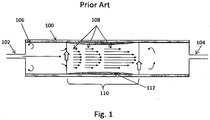
- FIG. 1 illustrates an example of the reactor 100 used in the '717 publication methods.
- the reactor 100 has a single input 102, such as a cylinder, pipe or conduit, and a single output 104, such as a cylinder, pipe or conduit. All reactant gases, dopant gases and catalytic seed particles (if used) are provided to the reactor 100 through the input 102 and are removed from the reactor 100 though the output 104. On entering the reactor 100, some of the gas forms eddies 106 in the corners due to edge effects in the reactor 100. These eddies create or add to non-ideality in the gas flow in the reactor 100.
- the reactor 100 has one or more heaters (not shown) that create a reaction zone 110 within the reactor 100.
- the reaction zone 110 is a region in the reactor 100 which is hot enough to cause decomposition of the precursor(s) and promote nanowire growth in the gas phase.
- the wall of the reactor 100 asserts a viscous force on the gases passing through the reactor 100, which results in the gas passing through the reactor 100 adjacent the walls to have a slower velocity than the gas passing through the center of the reactor 100.
- the relative velocity of the gas in the reactor 100 is illustrated with flow conduits 108.
- the slow moving precursor gas adjacent to the wall of the reactor 100 may react with the wall of the reactor 100 and form a deposit 112.
- concentric flows are used to reduce the variability of the flow, temperature and gas concentration conditions in the core part of the flow.
- every particle will have a substantially similar process history, as compared to the '717 publication where, even in the laminar flow case, particles will pass through the reactor 100 with a range of velocities.
- the core and sheath flows can be matched to initially give a "plug" flow condition, where the gas velocity is the same over the entire cross section of the reactor (i.e. a cross section perpendicular to the flow direction). As the flow proceeds through the reactor, surface drag will slow the outermost part of the gas.
- the flow may or may not have time to fully develop into a laminar flow with a parabolic velocity distribution.
- the ideal plug flow condition can partially be maintained by designing the extractor portion of the reactor (e.g. the outer output portion 204A described below) to pull the sheath gas uniformly. Even in the case of fully laminar flow, the core region will have a narrow velocity distribution, and thus a narrow range of transit times for the catalytic particles.
- the sheath flow reduces both the deposition of material on the side wall of the reactor 200 and, even more importantly, eliminates the back-diffusion of material from the wall to the core flow, ensuring that there is minimal cross-talk between the reaction volume and the reactor wall. Thereby, process stability is also improved in time, leading to better product and longer maintenance intervals.
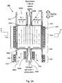
- FIG. 2A illustrates an aerotaxyTM nanowire growth reactor 200 according to an embodiment of the invention.
- AerotaxyTM is a trademark of Qunano AB and refers to a gas phase nanowire growth process.
- the reactor 200 includes a housing 201 (e.g. a CVD reaction tube), which is preferably oriented vertically, but which may be oriented horizontally.
- the reactor 200 also includes an outer input 202A, an inner input 202B, an outer output 204A and inner output 204B to and from the reaction zone 210, respectively.
- the inner input 202B is located concentrically within the outer input 202A, although the inner input 202B may be off center, such as by 1-25%, such as by 1-10%.
- the outer input 202A and the inner input 202B may be inlet openings to the reaction zone 210 of the reactor 200, and can be connected to any suitable gas or aerosol delivery conduit, such as a cylinder, hose, pipe or manifold.
- outer input 202A and inner input 202B may be connected to inert gas inlet conduit 206A and precursor inlet conduit 206B, respectively, and inner output 208B and outer output 208A may be connected to an inner output conduit 208B and an outer output conduit 208A, respectively.
- the inner and outer inputs 202A, 202B are configured such that a second fluid delivered from the outer input 202A provides a sheath between a first fluid delivered from the inner input 202B and a wall 201 of the reaction chamber 200.
- This may be accomplished, for example, by preferably providing both the first and second fluids under laminar conditions and/or having the outer input 202A sufficiently wider (e.g.
- the thickness of the sheath (second) gas stream is such that the first gas stream does not substantially (e.g., 0-5 vol% come into contact with the wall) contact the wall of the reactor 200 while in the reaction zone 210. Under laminar or plug flow, the core flow lines will not hit the reactor walls. In this case, the sheath prevents gas from diffusing between the wall and the core flow.
- a first boundary condition 220 concerns the orientation of the reactor 200 in relation to gravity.
- the reactor 200 is oriented such that the direction of flow in the reactor 200 is substantially parallel to the force of gravity (e.g. within 0-10% parallel to the force of gravity). In this manner, gravity will not act to cause a mixing flow transverse to the flow of gases through the reactor 200.
- the gas flow may be configured in the direction of gravity, e.g. gas inputs located at the top of the reaction zone 210 such that the gas streams flow "down" through the reaction zone 210 to outputs located at the bottom of the reaction zone 210.
- the gas flow may be against gravity, e.g. gas inputs located at the bottom of the reaction zone 210 such that the gas streams flow "up" through the reaction zone 210 to outputs located at the top of the reaction zone 210.
- a second boundary condition 222 is drawn to uniform extraction of the sheath gas from the reactor 200.
- Non-ideality at the output end of the reactor 200 can be minimized or eliminated by configuring the outer output 204A such that the sheath gas is uniformly extracted from the reactor 200 reaction zone 210.
- a corresponding fourth boundary condition 226 is drawn to uniform injection of the sheath gas to the reactor 200 reaction zone 210.
- Non-ideality at the input end of the reaction zone 210 and through the reaction zone 210 can be minimized or eliminated with uniform injection of gases in the outer input 202A. The resulting uniform flow though the reactor 200 may be described as 'plug' flow.
- a third boundary condition 224 is uniform gas and wall temperature in the reaction zone 210.
- the wall temperature and the gas temperature uniform, such as a variance of less than 5%, e.g. 0-5%, in the reaction zone 210, the formation of convection currents can be reduced or eliminated. This in turn, reduces the likelihood of generating non-ideal flow conditions in the reactor 200.
- a fifth boundary condition 228 is drawn to maintaining a controlled temperature gradient in a first heating zone 212 in the outer inlet conduit 206A which is connected to inlet 204A. The temperature of the sheath gas may be raised to the desired reaction temperature in the first heating zone 212 with heater(s) 214 located adjacent to conduit 206A.
- the first precursor gas and the optional catalytic particles may be heated to the desired reaction temperature with second heaters 216.
- the precursor gases may be actively cooled until the point of entry into the reaction zone 210, in which case device 216 is a cooling device.
- device 216 may be referred to as a temperature control device (i.e., a heater and/or cooler).
- the reaction zone 210 may be heated with one or more heaters 230.
- several heaters 230 are located along the reaction zone 210. These heaters 230 may be configured to be controlled independently and thereby more than one reaction zone 210 may be established within the reactor 200.
- Inert gas may be provided to the outer input 202A via the outer input conduit 206A.
- One or more semiconductor nanowire precursor gases may be provided to the inner input 202B via the inner input conduit 206B.
- the rector 200 does not include a growth or deposition substrate in the reaction zone; instead the nanowires are collected from the inner output conduit 208B via the inner output 204B and then deposited on a substrate. Additionally, the nanowires grown the by the methods of the present application do not need laser assistance for growth.
- Sheath gas exiting the reactor 200 reaction zone 210 can be collected through the outer output 204A while the nanowires and unreacted precursor gas can be collected through the inner output 204B. If an inert gas is used as the sheath gas, some unreacted precursor gas may mix with the inert gas in the reactor 200 and exit via the outer output 204A. This unreacted precursor gas may be separated from the inert sheath gas and recycled for later use in the reactor 200.
- catalytic particles may be provided to one or more of the gas flows in this embodiment or the embodiments that follow.
- Catalyst materials include, but are not limited to, Au, Ag, Cu, Fe, Ni, Ga, In, Al and alloys thereof.
- the catalytic particles may consist of a single element, or a combination (e.g. alloy) of two or more elements. Further, the catalyst particles may be provided without electrical charge or the catalytic particles may be given a charge.
- the catalytic particles may be provided in the form of an aerosol generated by an upstream aerosol generator. Alternatively, the catalyst particles may be formed in-situ by providing a gaseous precursor (e.g.
- trimethyl gallium (TMG) that reacts or decomposes to form catalyst (e.g. Ga) particles.
- Inert gas forms an outer sheath or cylinder along the reactor wall 201
- a catalyst particle aerosol forms or is provided to a middle sheath or cylinder inside the outer sheath
- nanowire precursor(s) form an inner gas stream inside the middle sheath which interacts with the catalyst particles in the middle sheath to grow nanowires therein.
- one or more of the precursor gases may also be provided to the outer input conduit 206A, thus being allowed to diffuse into the flow of catalytic particles.
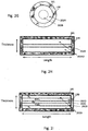
- the concentric aerotaxyTM reactor can be any shape from cylindrical (e.g., having a circular cross section perpendicular to the gas flow direction) to elliptical cylinder shape (e.g., a cylinder having an oval base and cross section perpendicular to the gas flow direction), to any polyhedron shape, such as a box-shape which can also be referred to as a cuboid, a rectangular prism or right-angled parallelepiped.
- Polyhedron shapes other than box-shapes having any polygonal cross sectional shape parallel or perpendicular to the gas flow direction e.g., a pentagon, hexagon, etc.
- the sheet-formed core flow from input 202B has a thickness than is at least 2 times, such as 5-50, or 10-100 times smaller than its length.
- the core-flow is sandwiched between two portions of the sheath-flow from inputs 202A located on both sides of the input 202B in the thickness direction. If the aerosol is not injected close to the edge of the reactor, then edge effects would be minimal and the thickness may be 5-10 times smaller than the length. Alternatively, if there is aerosol injected close to the edge, then the thickness may be 50-1000 times, such as 100-500 times, smaller than the length so that chamber edge effects on the flows are negligible.
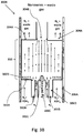
- the cylindrical reactor of Figure 2G facilitates superior flow-symmetry, while the box-shaped reactor of Figure 2H can be scaled up to large dimensions while retaining transverse flow dimensions and their ratios (pulp/pip ratios), as to still apply for rates of diffusion and intermixing of source materials and catalytic particles between the flow regions.
- the division into core and sheath flow are illustrated by the examples in Figures 2A-2F and 3A-5 which are to be regarded as having cross section of either a cylinder shown in Figure 2G or an extended flat cuboid geometry with arbitrary extension in/out of the image plane shown in Figure 2H or any shape in between.
- the reactor has an extended flat geometry (e.g., the cuboid shape of Figures 2H and 2I ).
- an additional degree of freedom is introduced regarding the flows and especially the injection of growth precursors.
- the group III-containing molecules e.g. trimethyl gallium, TMG
- TMG trimethyl gallium
- the group V-containing precursor molecules e.g., AsH 3
- the sheath flows are injected in the outer portions of the apparatus from inlets 202A in the thickness direction.
- FIG. 3A illustrates an aerotaxyTM nanowire growth reactor 300A according to another embodiment of the invention.
- the reactor 300A of this embodiment includes three inputs 302A, 302B, 302C and three outputs 304A, 304B, 304C.
- the three inputs 302A, 302B, 302C and three outputs 304A, 304B, 304C may be respective inlet and outlet openings to any suitable delivery or extraction conduit, such as a cylinder, hose, pipe or manifold.
- each of the three outer, middle and inner inputs 302A, 302B and 302C is connected to a respective one of the outer, middle and inner conduits 306A, 306B and 306C.
- the sheath gas is provided to the outer most input 302A.
- the tri-axial configuration of Fig. 3A can be used to control the timing of the precursor arrival at the catalyst particles.
- the catalyst particles can be pre-mixed with the group III precursor (e.g., TMG) and sent through input 302C, while the group V precursor (e.g., AsH 3 ) is mixed with the sheath gas and sent into the chamber through input 302A, while the input 302B is provided with clean (i.e., pure or unmixed) sheath gas.
- the group III precursor e.g., TMG
- group V precursor e.g., AsH 3
- the catalyst particles are pre-alloyed with the group III metal (e.g., Ga is pre-alloyed with Au or Ag catalyst particles) from the group III precursor before encountering the group IV precursor (e.g., AsH 3 ) which enters the catalyst / group III core flow through diffusion.
- group III metal e.g., Ga is pre-alloyed with Au or Ag catalyst particles
- group IV precursor e.g., AsH 3
- the difference in timing is controlled by the magnitude of the clean sheath flow into input 302B.
- the mixing of reactants can be further controlled by injecting different gases on either side of the core flow, and by using different flows; the timing can be independently controlled by using different settings of the clean middle sheath flow on either side of the core flow.
- catalytic particles such as gold or silver particles
- the middle input 302B may be provided to the middle input 302B.
- the catalytic particles may include individual metals or alloys.
- the catalytic particles are provided in the form of an aerosol generated by an upstream aerosol generator.
- One or more nanowire precursor gases may be provided to the inner input 302C.
- one or more doping gases may also be provided to the inner input 302C to dope the growing nanowire.
- the precursor and doping gases may be provided to the middle input 302B while the catalytic nanoparticles are provided to the inner input 302C.
- one or more precursor may be provided either of the middle input 302B or the inner input 302C while a second, different precursor is provided to the other of the middle input 302B or the inner input 302C.
- catalytic particles may be provided to either or both of the middle input 302B and the inner input 302C.
- One or more of the precursor gases may also be provided to the outer input 302A, thus being allowed to diffuse into the flow of catalytic particles.
- the inputs 302A, 302B, 302C are configured such that the gas delivered from the outer input 302A provides a sheath between the precursor gases/catalytic particle aerosol the wall of the reaction chamber.
- the growing nanowires in the central gas steam from inputs(s) 302A, 302B will experience essentially the same process conditions for essentially the same amount of time and thereby nanowires can be grown having a narrow range of controlled dimensions.
- Sheath gas exiting the reaction zone 310 is collected with the outer output 304A.
- the unused precursor gas(es) and the nanowires are collected in with the middle and inner outputs 304B, 304C.
- nanowire and waste gas may be collected in the middle output 304B, waste gas in the inner output 304C and waste gas in the outer output 304A.
- unused precursor gas entrained in the sheath gas may be separated from the sheath gas and reused.
- Fig. 3A illustrates several advantages of the concentric aerotaxyTM nanowire growth reactor. Since the catalyst particles have relatively high mass and low vapor pressure their mixing due to inter-diffusion is fairly slow and will thus remain in the core gas flow.
- the group III precursor, such as TMG (and its thermally decomposed Ga-comprising reactants) and group V precursor, such as AsH 3 have a relatively high gas phase diffusion rate and will tend to establish a constant concentration in the plane vertical to the flow.
- a core reaction-flow comprising homogeneously mixed TMG and catalyst particles can be readily established before AsH 3 is introduced.
- AsH 3 nucleation and epitaxial growth can be initiated instantaneously, facilitating the fabrication of homogeneously dimensioned layers and nanowires.
- Source material utilization in traditional (non-vacuum) epitaxy, using flat substrates, is mainly limited by parasitic wall reactions, parasitic gas phase reactions and substantial over-use of material to establish flow and concentration profiles that lead to homogeneous layer growth rates over large substrate areas.
- the concentrations at the growth front are limited by gas phase diffusion through the so-called stagnation layer, formed between the incoming gas flow and the epitaxial growth front at the substrate surface; therefore, a source-rich inlet flow is needed in order to reach source concentrations sufficient for intended epitaxial growth rates at the epitaxial surface, or growth front.
- the concentrations in the incoming flows need to be appreciably higher than the concentration at the growth front in order to be sufficiently constant over the extent of the substrate area.
- Concentric aerotaxyTM differs fundamentally from substrate growth in that the growth front is distributed in the gas (in the form of catalytic particles) and thus growth is not diffusion limited. This essentially eliminates the stagnation layer related to the flat substrate, and allows higher source concentrations than those used in planar epitaxy, without leading to gas phase reactions. Source gas concentrations can be set to the levels needed at the growth front, which reduces the fraction of unused source material in the gas. Furthermore, in the concentric aerotaxyTM reactor the epitaxial growth fronts are brought along with the reactants, in contrast to traditional growth, where reactants are made to pass over the substrate, further extending the ability to improve source utilization. With the reactive flow localized to the core of the reactor and the use of higher gas concentrations, much higher growth rates are achieved.
- the depletion of source gases over time will mainly be due to crystal growth, not parasitic reactions, and will be a function of residence time, initial concentrations, epitaxial reaction rates and position in the reactor. All this yields an unprecedented high growth rate, combined with a high source utilization of between 20% to 30% of at least one of the growth sources (i.e., precursors), and preferably above 40% or 50%.
- a source utilization of at least one the sources is higher than 60% or 70%, such as 60-75%.
- the utilization of at least one and preferably all growth precursors, such as TMG and AsH 3 for GaAs nanowire growth is between 20% and 75%, preferably 40-75%.
- Figure 3B illustrates an aerotaxyTM nanowire growth reactor 300B according to another embodiment of the invention.
- the precursors are provided via separate inlets and are preferably separated from each other by a sheath gas flow stream.
- the reactor 300B of this embodiment includes four inputs 302A, 302B, 302C, 302D and two outputs 304A, 304B.
- the reactor 300B has an additional input 302D compared to reactor 300A of Figure 3A and one less output compared to reactor 300A.
- the inputs and outputs may be respective inlet and outlet openings to any suitable delivery or extraction conduit, such as a cylinder, hose, pipe or manifold.
- each of the four outer, inner middle, outer middle and inner inputs 302A, 302B, 302D and 302C is connected to a respective one of the outer, inner middle, outer middle and inner conduits 306A, 306B, 306D and 306C.
- the sheath gas is provided to the outer most input 302A and to the adjacent outer middle input 302D.
- the catalytic particles such as gold or silver particles, may be provided to the inner input 302C.
- the catalytic particles may include individual metals or alloys.
- the catalytic particles are provided in the form of an aerosol generated by an upstream aerosol generator.
- One or more nanowire precursor gases may be provided to the inner middle input 302B and the other one or more nanowire precursor gases may be provided to the outer input 302A together with the sheath gas.
- the group III precursor gas such as TMG is provided to the inner middle input 302B while the group V precursor gas, such as AsH 3 may be provided to the outer input 302A such that it is mixed with the sheath gas.
- the group III precursor gas flows around the inner catalytic particle flow, while the sheath gas (e.g., nitrogen) from the middle outer input 302D provides a sheath between the group III precursor gas flow and the group V precursor gas flow (which is mixed with the sheath gas) in the apparatus.
- the sheath gas e.g., nitrogen
- the group III precursor gas flows around the inner catalytic particle flow, while the sheath gas (e.g., nitrogen) from the middle outer input 302D provides a sheath between the group III precursor gas flow and the group V precursor gas flow (which is mixed with the sheath gas) in the apparatus.
- the sheath gas e.g., nitrogen
- nucleation and epitaxial growth can be initiated instantaneously, facilitating the fabrication of homogeneously dimensioned layers and nanowires. It is well known in the art of substrate-based nanowire growth that nanowires preferentially grow with good quality from pre-alloyed seed particles.
- the separation in time and space of the growth precursors leads to pre-alloying of, for example, catalyst metal particles and group III metals from the group III precursor (e.g., pre-alloying of Au and Ga) and gives substantially defect-free nanowire growth.
- pre-alloying can be performed by placing the inputs of the catalyst particles and the at least one source element (e.g., the group III precursor such as TMG) closer to each other and/or upstream compared to the input of a second precursor (e.g., the group V precursor), to enable flight of time for pre alloying.
- the at least one source element e.g., the group III precursor such as TMG
- a second precursor e.g., the group V precursor
- one or more doping gases may also be provided to the input(s) 302A and/or 302B to dope the growing nanowire.
- the unused precursor gas(es) and the nanowires are collected in with the outer and inner outputs 304A, 304B.
- nanowire and waste gas may be collected in the inner output 304B, and waste gas and sheath gas in the outer output 304A.
- unused precursor gas entrained in the sheath gas may be separated from the sheath gas and reused.
- Figures 2B, 2C , 2D and 2E illustrate additional embodiments of methods of operating the aerotaxyTM nanowire growth apparatus 200 of FIG. 2A .
- Figure 2B illustrates the fluid behavior in the apparatus 200 when operating with a low core flow (i.e. the core flow rate is less than the sheath flow rate) while
- Figure 2C illustrates the fluid behavior in the apparatus 200 when operating with a high core flow (i.e. the core flow rate is greater than the sheath flow rate).
- the residence time of the nanowires in the apparatus 200 may be influenced by controlling the ratios of flows (i.e. flow rates) in the core (inlet 202B) and sheath (inlet 202A) regions.
- Figures 2D and 2E depict how the width of the core reaction flow can be expanded and decreased by applying asymmetrical input and output ratios between sheath and core flow.
- Figure 2D illustrates the fluid behavior in the apparatus 200 when operating with matched (i.e., the same or similar) core and sheath flow at the inlet, and lower sheath flow compared to core flow at the outlet.
- the mean velocity of the core gas is higher than that of the sheath gas at the outlet, then the core gas flow (and any catalytic particles contained within) will expand resulting in an expansion 1404 of the diameter of core gas stream at the outlet 204B.
- Figure 2E illustrates the fluid behavior in the apparatus 200 when operating in inverse mode to that shown in Figure 2D .
- the apparatus is with matched core and sheath flow at the outlet and lower sheath flow compared to core flow at the inlet.
- the mean velocity of the core gas is higher than that of the sheath gas at the inlet, then the core gas flow (and any catalytic particles contained within) will expand resulting in an expansion 1404 of the diameter of core gas stream at the inlet 202B.
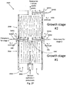
- Figure 2F illustrates an aerotaxyTM nanowire system 1500 with series connected aerotaxyTM nanowire growth apparatuses 200A, 200B according to another embodiment.
- the nanowire system 1500 include two growth stages, i.e., the system includes two nanowire growth apparatuses 200A, 200B described in the previous embodiment in which the core outlet of the first state is connected to the core inlet of the second stage.
- the system 1500 may have any number of nanowire growth apparatuses/stages, such as three or more stages. Further, the system 1500 may include any of the embodiment of the nanowire growth apparatuses 200, 200A, 200B, 300A, 300B, 400, discussed herein. Additionally, the system may include nanowire growth apparatuses 200, 200A, 200B, 300A, 300B, 400 in any combination, and/or including a stack in which all of the apparatus are of the same embodiment. Thus, for example, the system 1500 may be configured with any combination of reactor(s) 200A having a higher core flow than sheath flow and/or reactor(s) 200B having a lower core flow than sheath from. Further, by stacking reactors with different relative flow rates, the system may take advantage of the Venturi effect to further vary the size of the core flow.
- the system 1500 includes a gap between adjacent nanowire growth apparatuses 200, 200A, 200B, 300A, 300B, 400 in the stack through which feed conduits (e.g. 504B1, 504B2) and gas outlets (e.g. 440) may be provided.
- feed conduits e.g. 504B1, 504B2
- gas outlets e.g. 440
- a feed conduit 504B1 may be configured to provide sheath gas to the outer input conduit 206A of the second reactor 200B
- a feed conduit 504B2 may be configured (e.g., it extends to and/or points at the core flow area between the reactors 200A, 200B) to provide precursor(s) and/or catalyst particles to the inner input conduit 206B of the second reactor 200B.
- the sheath gas and entrained precursor gas i.e.
- waste gas in the sheath gas may be removed with gas outlets 440, 440A.
- new precursors and sheath gas may be supplied to each new stage and old sheath gas and waste gas removed.
- the stages can be stacked vertically, horizontally or any combination in between. In an embodiment, the entire stack is enclosed in an outer housing (not shown).
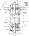
- FIGS 4A, 4B and 5 illustrate another embodiment of an aerotaxyTM nanowire growth reactor 400 which is similar to the reactor 200, but which contains additional elements.
- the reactor 400 includes an outer input 402A, an inner input 402B, an outer output 404A and inner output 404B.
- the sheath gas is provided to the outer input 402A from a reservoir, discussed in more details below, via a sheath gas inlet 432 located in an outer input conduit 406A.
- the catalyst may be aerosolized and provided to the inner input 402B via a catalyst inlet 434 located in an inner input conduit 406B.
- One or more precursor gases may be provided to the inner input 402B via a precursor inlet 436 to the inner input conduit 406B.
- Inlets 432, 434, 436 may comprise any conduits, such as a cylinder, hose, pipe or manifold.
- Sheath gas inlet 432 is located in the outer input conduit 406A.
- the catalyst aerosol inlet 434 and the precursor inlet 436 are located in the inner input conduit 406B, with the precursor inlet 436 extending farther up the inner input conduit 406B than the catalyst inlet 434.
- the temperature of the sheath gas, catalyst aerosol and precursor gases may be monitored at the outer and inner inputs 402A, 402B and in the outer and inner input conduits 406A, 406B with one or more thermocouples 420.
- Heat may be supplied to the outer input conduit 406A, the reaction zone 410 and the outer output conduit 408A with one or more heaters 430.
- heat may be transferred from the outer input conduit 406A to the inner input conduit 406B via transfer elements 438 located in a lower portion of the reactor 400.
- heat may be transferred from the inner output conduit 408B to the outer output conduit 408A via transfer elements 438 located in an upper portion of the reactor 400.
- the heat transfer elements 438 may be, for example, disks made of material with a high thermal conductivity, such as aluminum or copper as shown in Figure 4B .
- the distal end (furthest from the reaction zone 410) of the outer input conduit 406A may be provided with a heat shield/insulation 418 (e.g. a material with a low thermal conductivity).
- the heat shield/insulation 418 reduces heat loss out of the outer input conduit 406A and thereby aids in maintaining a stable temperature gradient in the outer input conduit 406A.
- the outer input conduit 406A may be provided with one or more frits or filters to provide an equilibrated pressure ensuring a circularly symmetrical plug flow.
- the outer input conduit 406A is provided with one or more low porosity, e.g., frits or filters 424 and/or one or more high porosity, e.g., frits or filters 422.
- the low porosity frits or filters 424 may be made of any suitable material such as sintered stainless steel.
- the high porosity frits or filters 422 may be made of any suitable material, such as metal or ceramic wool or woven fiber such as SiO 2 , Al 2 O 3 , or steel wool.
- the outer output conduit 408A may be provided with a cooling collar 426.
- the cooling collar 426 has a fluid input 428 and a fluid output 430.
- the fluid may be either a liquid or gas.
- the cooling collar 426 extracts heat from the outer output conduit 408A and thereby cools the sheath gas. Additionally, if heat transfer elements 438 are provided in the outer output conduit 408A as discussed above, heat may be extracted from the inner output conduit 408B and thereby cool the unreacted precursor gas(es) and the nanowires.
- the temperature of the outer output conduit 408A and the inner output conduit 408B may be monitored with one or more thermocouples 420.
- the sheath gas may be removed from the outer output 404A via conduit 408A and a gas outlet 440 and sent to a reservoir as discussed in more detail below.
- the unreacted precursor gas and the nanowires may be removed from the reactor 400 via an outlet 442 from the inner outlet conduit 408B.
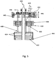
- FIG. 5 illustrates and provides more detail of the exit portion of the aerotaxyTM nanowire growth reactor 400.
- the exit portion is essentially identical to the inlet portion to maintain symmetric gas flow.
- the high porosity frits/filters 422 and the low porosity frits/filters 424 may be assembled in a housing 444.
- the housing 444 may be made of any suitable material, such as stainless steel or molybdenum.
- Sheath gas flowing from the reaction zone 410 through the high porosity frits/filters 422 and the low porosity frits/filters 424 is channeled into a conduit or pipe 448 which passes through the heat shield 418 and one or more heat transfer elements 438 located in outer output conduit 408A on the way to the sheath gas outlet 440.
- the heat shield 418 and one or more heat transfer elements 438 may be held in place above the housing 444 with clamps 450 secured to the conduit or pipe 448.
- Other suitable fastening devices may be used to hold the heat shield 418 and the heat transfer element(s) 438 in place, such as screws, bolts and the like.
- the size of the reaction zone 410 can be adjusted by raising or lowering the outer and inner inputs 402A, 402B, the inner and outer outputs 404A, 404B (indicated by range 446) or both. This adjustment can be made by operation of an adjustment mechanism 445, such as a screw or lever or any other suitable mechanism, which raises or lowers the inner and outer input conduits 406A, 406B and/or the inner and outer output conduits 408A, 408B or the top cap 452 of the assembly 440, 442, 444, 448, 438 in outer output conduit 408A such the outputs 404A and 404B from the reaction zone 410 are raised or lowered.
- the size of the reaction zone 410 can be adjusted by replacing the reactor tubes (inlet conduits 206A, 206B and outlet conduits 208A, 208B), preferably the outer conduits 206A, 208A with reactor tubes of different length.
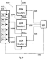
- FIG 6 illustrates an embodiment of an aerotaxyTM nanowire growth system 500.
- the system has three aerotaxyTM nanowire growth reactors 200A, 200B, 200C according to the first embodiment.
- the system 500 may have one or more aerotaxyTM nanowire growth reactors 200, 300A, 300B, 400 of any of the previously described embodiments.
- the three aerotaxyTM nanowire growth reactors 200A, 200B, 200C are configured in series. That is, nanowires exiting the first aerotaxyTM nanowire growth reactor 200A are provided to the second aerotaxyTM nanowire growth reactor 200B and nanowires exiting from the second aerotaxyTM nanowire growth reactor 200B are provided to the third aerotaxyTM nanowire growth reactor 200C.
- the aerotaxyTM nanowire growth reactors may be configured in parallel or in a combination of series and parallel.
- the connections 508A, 508B between aerotaxyTM nanowire growth reactors 200A, 200B, 200C may be made with any suitable conduits, such as pipes, manifolds, hoses or any other suitable connector.
- the final nanowires may be harvested via conduit 508C.
- further separation of precursor injection can be achieved with high degree of control by using one aerotaxyTM reactor only for the pre-alloying of the catalyst particles, and the subsequent reactors for the nanowire growth.
- the catalyst particles and one of the precursors e.g., the group III precursor, such as TMG
- the sheath gas are provided into the first reactor 200A to form pre-alloyed catalyst particles (e.g., group III-noble metal pre-alloyed particles, such as Ga-Au or Ga-Ag pre-alloyed particles).
- the pre-alloyed particles and the first precursor are then provided from the first reactor 200A into a second reactor 200B.
- the second precursor (e.g., group V precursor, such as AsH 3 ) and the sheath gas are also provided into the second reactor 200B to form nanowires in the second reactor using the pre-alloyed catalyst particles.
- Fig. 2E shows a compact implementation of such a reactor stack, where the precursor injector lines would need to be actively cooled, e.g., using water cooling, and the inner aerosol conduit 206C and sheath gas inlet 504B1 to be actively heated, e.g., using electrical heaters.
- the system 500 includes six reservoirs R1-R6. However, any number of reservoirs may be included such as 2, 3, 4, 5, 6, 7, 8, 9, 10 or more as desired.
- the first reservoir R1 may contain, for example, a first precursor gas, such as trimethyl gallium or triethyl gallium.
- the second reservoir R2 may contain a second precursor gas, such as arsine or an inert carrier gas, such as nitrogen, argon or helium.
- the third reservoir R3 may include a second precursor gas, an inert gas (e.g. a sheath gas) or a first dopant gas having a first conductivity type.
- the fourth reservoir R4 may include a second dopant gas having a second conductivity type different from the first conductivity type.
- nanowires can be grown with layers (e.g. core-shell(s)) or regions of different conductivity type.
- layers e.g. core-shell(s)
- regions of different conductivity type e.g. both longitudinally oriented and radially oriented nanowires can be fabricated with this system.
- nanowires having one or more pn or p-i-n junctions can be fabricated.
- Reservoir R5 may include aerosolized catalyst particles.
- reservoir R5 includes powder catalyst particles, however the powder catalyst particles may be combined and aerosolized with a carrier gas in an aerosolizer 520.
- Suitable aerosol carrier gases include, but are not limited to, nitrogen, hydrogen and noble gases such as helium and argon.
- longitudinally and radially oriented nanowires having one or more pn junctions can be fabricated continuously. That is, raw materials are continuously provided at a first end of the system and finished nanowires are continuously collected at a second end of the system without having to stop the system.
- the type and concentration of the gases and the operating conditions may be independently varied in all of the reactors 200 in the system 500, both homostructures and heterostructures may be fabricated, such as with respect to composition, doping and/or conductivity type. Further, the type and concentration of the gases and the operating conditions may be varied as a function of time within a reactor 200.
- one or more reservoirs R1-R6 may contain aerosolized catalyst particles.
- one reservoir may simply include catalyst particle powder.
- the powder may be mixed with a precursor gas or inert gas in an aerosolizer and thereby be aerosolized prior to being provided to the reactor 200.
- a catalyst particle aerosol is generated by generating catalyst particles, e.g. by evaporation of gold, in an aerosolizer and combining the catalyst particles with a gas in the aerosolizer.
- the gases and optional catalyst aerosol are provided to the reactors 200A, 200B, 200C with feed conduits 504A, 504B, 504C which connect outputs to inputs of adjacent reactors.
- the feed conduits may be a pipe, conduit, hose, manifold or any other suitable delivery tube.
- the temperature of the reactors 200A, 200B, 200C can be monitored with one or more thermocouples 420.
- the gas or aerosol flow from the reservoirs R1-R6 to the reactors 200A, 200B, 200C may be monitored with mass flow indicators 510. Data from the thermocouples 420 and the mass flow indicators/controllers 510 may be sent to a controller 502, such as a personal computer, server, or special purpose computing device.
- the data may be sent via wires 506 or may be sent wirelessly with the use of wireless transceivers.
- the controller 502 includes software which can analyze the data and send feedback instructions to the heaters 214, 216 and/or to gas flow controllers 515 of reservoirs R1-R6 (e.g. computer controllable flow control valves) to increase or decrease the temperature in the reactors 200 or to increase or decrease the flow of the aerosol or gases to the reactors 200.
- Figures 7A and 7B illustrate additional embodiments of aerotaxyTM nanowire growth systems 700A, 700B.
- the system 700A includes a first reservoir R1 configured to deliver a precursor gas to the reactor 200 (or 300, 400).
- the precursor gas may include catalyst particles delivered from an aerosol reservoir.
- the system 700A also includes a second reservoir R2 configured to deliver a sheath gas.
- the sheath gas may be a second precursor gas or an inert gas, e.g. nitrogen or a noble gas such as helium or argon.
- the system 700A further includes a particle analyzer 704 which provides in-situ analysis of the nanowires or the partly grown nanowires to obtain the desired nanowire properties.
- the particle analyzer 704 may operate, for example, by illuminating the nanowires and detecting the luminescence from the nanowires to determine optical properties of the nanowires. In-situ analysis provides the ability to obtain feed-back in a control loop that is not available in substrate-based synthesis of nanowires.
- the feed-back may be used to control wire growth, such as by controlling the size of the catalytic seed particles, as well as control of growth conditions by controlling one or more parameters associated with: precursor composition, precursor molar flow, carrier gas flow, temperature, pressure or dopants, in one or more of the reaction zones.
- the nanowires are provided to a nanowire repository 706 (e.g. a container for storage of the nanowires or a nanowire deposition apparatus containing a substrate).
- the system 700B includes a first reservoir R1 and a second reservoir R2.
- the first reservoir R1 may be configured to provide a precursor gas and the second reservoir R2 configured to provide a sheath gas.
- the system 700B includes a plurality of reactors 200 configured in series and parallel. With this system 700B, a large number of nanowires may be fabricated simultaneously. Further, each parallel line of reactors 200 may be operated under different conditions from the other conduits of reactors 200 in the system 700B. In this manner, different configurations of nanowires, e.g. longitudinally oriented and horizontally oriented, may be produced simultaneously. In another aspect, different conduits of reactors 200 may be provided with different size nanoparticles.
- the system 700B illustrated in Figure 7B may include one or more particle analyzers 704 to monitor the nanowire growth in one or more of the conduits of reactors 200.
- the nanowire growth apparatuses 200, 200A, 200B, 300A, 300B, 400 may be aligned horizontally or vertically, (e.g. for a vertical alignment of a nanowire growth apparatuses 200, the outer input 202A and the inner input 202B are vertically aligned with the outer output 204A and inner output 204B, respectively).
- the nanowire growth apparatuses 200, 200A, 200B, 300A, 300B, 400 may be vertically stacked.
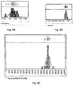
- Figures 8A and 8B provide a comparison of the size distribution of nanowires fabricated in the prior art reactor 100 of Figure 1 with nanowires fabricated in the reactor 200 of the embodiment of the invention illustrated in Figure 2 .
- the curved line in Figure 8A illustrates the size distribution assuming laminar flow in the reactor 100.
- the histogram illustrates the distribution of measurements of actual nanowires made with the reactor 100.
- Figure 8B is a plot of simulated distribution data for the reactor 200 of Figure 2 operated under the same conditions as the reactor 100 used to generate the data in Figure 8A , assuming that wire length is linearly proportional to the time each particle/wire spends in the reaction zone.
- Figure 8C is a plot of actual distribution data for nanowire grown in a reactor 200 illustrated in Figure 2A and described above, with core aerosol and sheath flows of 500 and 1200 sccm, respectively; with system at atmospheric pressure; and at a reaction temperature of 500 °C.
- the nanowires produced by the reactor 100 have a much wider size distribution than the nanowires produced by the reactor 200.
- the standard deviation of the length distribution formed by the reactor 100 is approximately 30% of the value of the mean nanowire length, in the worst case assumption of fully developed laminar flow throughout the reactor 200.
- the simulated standard deviation ( Fig.
- the standard deviation of the nanowire lengths produced by the reactor 200 in this example is at least 10 times smaller than the standard deviation of the nanometer lengths produced by the reactor 100.
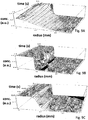
- Figures 9A-9C illustrate simulated plots of concentration versus distance (reactor radius) for the diffusion of trimethyl gallium (TMG), 50 nm Au particles for 1 second and 50 nm Au particles for 200 seconds, respectively provided in an inner input 202B of a reactor 200.
- TMG trimethyl gallium
- the simulations are based on a reactor 200 in which the inner input 202B has a radius of 9 mm and the outer input 202A has a radius of 27 mm.
- the diffusion coefficient used for TMG was 1.98 x 10 -5 m 2 /s and the diffusion coefficient for the 50 nm Au particles was 3.28 x 10 -9 m 2 /s.
- diffusion was the only mixing mechanism. That is, turbulence, mixing and convection were set to zero in the simulation.
- the simulated TMG began to diffuse laterally into the sheath gas after approximately 0.2 seconds.
- concentration of TMG in the center of the inner input 202B has dropped from 100% to 70%.
- concentration in the sheath gas adjacent the inner input 202B e.g. at a radius of 10 mm, has risen from 0% to approximately 30 %.
- the gold particles because of their much lower diffusion coefficient, have barely diffused into the sheath, even after 20 seconds.
- the gold particles exhibit good plug flow for a wide range of reactor lengths and are well contained by the sheath flow.
- Embodiments of the invention also include methods for forming nanowires that allow for large scale production combined with a structural complexity and material quality comparable to nanowires formed using substrate-based synthesis.
- One method includes providing a first gas to the first input conduit to a reaction chamber, such as a tube furnace.
- the first gas preferably includes a first precursor material for fabricating the nanowires.
- the first gas may be trimethyl gallium (TMG) which dissociates into gallium and methane at elevated temperatures, thereby providing gallium for gallium based nanowires, such as semiconducting GaAs nanowires.
- TMG trimethyl gallium
- a second gas is provided to the reaction zone of the reaction chamber through the first input.
- the second gas may comprise a second, different precursor, such as arsine which dissociates into arsenic and hydrogen.
- the gallium forms droplets which catalyze the dissociation of arsine and the growth of the GaAs nanowire.
- the sheath gas is provided through the second input; optionally, catalyst particles are provided through the first input.
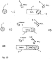
- FIG. 10 is a schematic illustration of axial growth a nanowire 1 comprising a pn junction according to an embodiment.
- the method includes providing catalytic particles 2 suspended in a gas and providing first and second gaseous precursors 3, 4, e.g. TMG and AsH 3 , that include constituents of the nanowires 1 to be formed into a reaction zone.
- the method also includes growing single crystal nanowires 1 from the catalytic particles 2 in a gas-phase synthesis which includes the first and second gaseous precursors 3, 4 while the catalytic particles are suspended in the gas(es).
- the first and second precursor gases 3, 4 may be provided to the reactor 200 at room temperature. Alternatively, the first and second precursor gases 3, 4 (as well as the dopant gases if used) may be pre-heated prior to delivery to the reactor 200.
- Nanowire growth is performed at an elevated temperature in any of the reactors 200, 300, 400 as described above. Growth is initiated by catalytic decomposition of the gaseous precursors 3, 4 on the surface of the catalytic particles 2 and nucleation of the nanowire on the surface of the catalytic particles 2. After nucleation, the nanowire 1 grows directionally and forms an elongated object, i.e. a nanowire 1. Growth may occur via vapor-liquid-solid (VLS) or chemical vapor deposition (CVD).
- VLS vapor-liquid-solid
- CVD chemical vapor deposition
- the gas flows through the reactor and thereby carries at least the catalytic particles 2 and thus the nanowires 1 formed on the catalytic particles 2 through the reactor.
- FIG. 10 schematically illustrates the formation of a GaAs wire 1 from a catalytic particle 2, such as gold, and first and second gaseous precursors TMG 3 and AsH 3 4.
- a catalytic particle 2 such as gold
- the catalytic particles 2 are carried forward by a feed gas into a reactor where the gaseous precursors 3, 4 are present and the reaction takes place.
- the precursor gases 3, 4 may be added to the gas flow prior to entering the reactor or directly to the reactor.
- the catalytic particles may be aerosolized in one of the precursor gases 3, 4 and added to the reactor via the inner input conduit 206B in the reactor 200 or via the inner input conduit 306C or the middle input conduit 306B in the reactor 300A.
- Figure 10 further schematically illustrates how a method of the invention can be used to form a GaAs nanowire 1 with an axial pn-junction between a p-doped GaAs segment and an n-doped GaAs segment.
- First and second precursors 3, 4 having group III material and group V material, respectively, and one or more p-dopants are provided to a reactor 200.
- a p-doped GaAs nanowire 1 is axially grown from the catalytic particle 2, thereby forming a first axial segment of the GaAs nanowire.
- the growth conditions are changed by exchanging the p-dopant with an n-dopant, while substantially maintaining other parameters related to the growth conditions, such that a second axial wire segment is axially grown on the previously formed first segment in a longitudinal direction.
- the growth conditions are changed by exchanging the p-dopant with an n-dopant, while substantially maintaining other parameters related to the growth conditions, such that a second axial wire segment is axially grown on the previously formed first segment in a longitudinal direction.
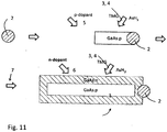
- Figure 11 schematically illustrates the formation of a GaAs nanowire having a radial pn-junction between a p-doped GaAs core and an n-doped GaAs shell.
- First and second precursors 3, 4 comprising group III material and group V material, respectively, and p-dopants are provided to the reactor.
- p-doped GaAs is axially grown from the catalytic particle 2, thereby forming the core of the GaAs nanowire 1.
- the growth conditions are changed by increasing the temperature and/or the V/Ill-ratio to promote radial growth and by exchanging the p-dopant to an n-dopant.
- the shell is radially grown on the previously formed core in a radial direction thereof.
- the nanowire by grown with an n-doped core and a p-doped shell.
- the nanowires may be collected upon the completion of growth and then deposited as a film on a substrate and/or oriented in a preferred orientation on a substrate (e.g., with the nanowire axis substantially normal to the substrate surface supporting the nanowires).
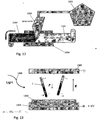
- Figure 12 illustrates a method of depositing nanowires on a substrate while Figure 13 illustrates a method of depositing and orienting nanowires on a substrate.
- nanowires are collected from the aerotaxyTM growth system 200, 300, or 400 into a storage reservoir 1201 and then provided from the reservoir to a spray nozzle 1202.
- the nanowires may be provided directly from the system 200, 300, or 400 (e.g., via exhaust 442) to the nozzle 1202 without being stored in the reservoir 1201.
- the spray nozzle sprays the nanowires onto a substrate 1203, such as sheet of metal, e.g. stainless steel, plastic, silicon or any other suitable material to form a nanowire film 1204, such as percolating network of nanowires, on the substrate.
- the nanowires 1 are aligned with their long axis perpendicular to the substrate 1303 using an electric dipole generated in the nanowires by an electric field in the deposition chamber 1300.
- an electric field, E may be generated in the deposition chamber by a potential difference (i.e., voltage) applied between a susceptor 1304 supporting the substrate and a top plate 1305 above the substrate having an aerosol inlet.
- the nanowires are provided from the reservoir or directly from the reactor shown in Figures 2-4 as an aerosol into the deposition chamber 1300.
- the electric dipole in the nanowires can, by way of example, be generated by one or a combination of the following:
- nanowires having different band gaps can be selectively aligned since wires that do not absorb the light will have a much weaker dipole.
- the nanowires may be aligned using a chemical surface modification method, where the nanowires are selectively functionalized to align them on a substrate, as described in U.S. provisional application serial number 61/623,137 filed in April 12, 2012 and in corresponding PCT application PCT/SE2013/050389 .
- III/V semiconductor materials as well as semiconductor materials comprising group II and group VI materials may be processed in the same way.
- gaseous precursors of the above examples can be exchanged for trimethyl indium (TMIn) and phosphine (PH 3 ) to form InP wires.
- TMIn trimethyl indium
- PH 3 phosphine
- the reactor configuration does not have to be changed to form wires from different gaseous precursors, the gaseous precursors are simply switched, e.g.
- the processes such as those exemplified by Figures 10 and 11 may be performed with or without the addition of dopants. Insulators may also be grown. Single or multiple reactors or reaction zones within a reactor can be used to improve the formation of segments, cores or shells having different composition, doping or conductivity type. Moreover, axial and radial growth is not necessarily fully decoupled, process conditions may be selected such that the nanowires grow both radially and axially at the same time. By choosing appropriate gaseous precursor, flows, temperatures, pressures, and particle sizes, the nanowire material can be made to grow in the axial or radial direction, or in a combination of the two growth modes.
- Sheath gases include, but are not limited to, nitrogen, hydrogen and noble gases such as helium and argon.
- Precursor gases include but are not limited to TMG, TMIn, TEG, TEIn, TMAl, TEAl, NH 3 , AsH 3 and PH 3 . Suitable dopants depend on the nanowire material being doped.
- Examples include, but are not limited to: (1) InGaAl-AsPSb: n-dopants: S, Se, Si, C, Sn; p-dopants: Zn, Si, C, Be; (2) AlInGaN: n-dopants: Si; p-dopants: Mg; (3) Si: n-dopants: P, As, Sb; p-dopants: B, AI, Ga, In; (4) CdZn-OSSeTe system: p-dopants: Li, Na, K, N, P, As; n-dopants: Al, Ga, In, Cl, I.
- a reactor 200 having an inner input 202B located concentrically within the outer input 202A is used to overcome the wall effects of the earlier gas methods of nanowire growth discussed above.
- a first gas and a second gas may be provided to the reaction chamber such that second gas forms a sheath separating the first gas from the wall of the reaction chamber.
- the first, inner gas is shielded from the detrimental effects of the temperature gradients and viscous effects caused by the walls.
- both the first gas and the second gas are provided with laminar flow.
- the gas carrying the catalytic particles and/or nanowires is substantially exchanged for the sheath gas in embodiments where the core and sheath gases are different. This may be advantageous for optimizing different chemical reactions in sequential reactor sections 200A, 200B, etc.
- catalytic seed particles 2 may be provided with the first precursor gas 3 and optionally the second precursor gas 4 in the first, inner input 202B as a common inner gas stream.
- the catalyst seed particles may be aerosolized in the first precursor gas 3 or separately aerosolized in a different gas and added to the first, inner input.
- the second gas includes a second precursor gas 4.
- the second gas may be an inert gas such as nitrogen, argon or helium.
- the first gas includes only one precursor gas 3, such as silane, which dissociates into silicon and hydrogen while the second gas is inert.
- single element nanowires such silicon nanowires, may be grown.
- one or more dopant gases may be included in the first gas.
- a doped, "single element" nanowire may be produced.
Landscapes
- Chemical & Material Sciences (AREA)
- Materials Engineering (AREA)
- Organic Chemistry (AREA)
- Metallurgy (AREA)
- Engineering & Computer Science (AREA)
- Crystallography & Structural Chemistry (AREA)
- Chemical Kinetics & Catalysis (AREA)
- General Chemical & Material Sciences (AREA)
- Inorganic Chemistry (AREA)
- Mechanical Engineering (AREA)
- Physics & Mathematics (AREA)
- Fluid Mechanics (AREA)
- Crystals, And After-Treatments Of Crystals (AREA)
- Physical Or Chemical Processes And Apparatus (AREA)
- Recrystallisation Techniques (AREA)
- Chemical Vapour Deposition (AREA)
Description
- The present invention relates to formation of wires and in particular to gas phase synthesis of wires in the absence of a substrate.
- Small elongated objects, usually referred to as nanowires, nanorods, nanowhiskers, etc. and typically comprising semiconductor materials, have up till now been synthesized using one of the following routes:
- liquid phase synthesis, for example by means of colloidal chemistry as exemplified
US 2005/0054004 by Alivisatos et al , - epitaxial growth from substrates, with or without catalytic particles as exemplified by the work of Samuelson et al presented in
WO 2004/004927 andWO 2007/10781 - gas phase synthesis by means of a laser assisted catalytic growth process as exemplified by
WO 2004/038767 A2 by Lieber et al. - Consequently, the choice of synthesis route is a compromise between different wire properties and the cost of production. For example, substrate-based synthesis provides advantageous wire properties. However, since wires are formed in batches, the scalability of the process, and thus the production cost and throughput, are limited.
-
GB2436398A
"High-Rate Particle Growth Using GaCl and NH3 as Sources in Two-Stage Vapor-Phase Method for Synthesis of GaN Powders" by Hara et al in Japanese Journal of Applied Physics, Volume 41, , discusses the exploration OF growth of crystalline GaN on GaN seed particles by the reaction of GaCl and NH3 in a gas flow, for the two-stage vapor-phase synthesis of GaN powders. The seed particles, which were formed by the reaction of vaporized Ga and NH3 at the first stage, were found to be indispensable as nucleation sites for the second stage of the particle growth. - An embodiment relates to a gas phase nanowire growth apparatus as disclosed in
claim 1 including a reaction chamber, a first input and a second input. The first input is located concentrically within the second input and the first and second input are configured such that a second fluid delivered from the second input provides a sheath between a first fluid delivered from the first input and a wall of the reaction chamber. As used herein, the term "concentric" has it common meaning of "having a common center". Thus, the concentric aerotaxy™ reactor can be any shape from cylindrical (e.g., having a circular cross section perpendicular to the gas flow direction) to elliptical cylinder shape (e.g., a cylinder having an oval base and cross section perpendicular to the gas flow direction), to any polyhedron shape, such as a box-shape which can also be referred to as a cuboid, a rectangular prism or right-angled parallelepiped - Another embodiment relates to a method of fabricating nanowires, as disclosed in claim 9. The method includes providing a first gas stream to a reaction chamber in which the first gas stream includes a first precursor for fabricating the nanowires and providing a second gas stream to the reaction chamber in which the second gas stream forms a sheath separating the first gas stream from a wall of the reaction chamber. The method also includes growing the nanowires in a gas phase in the reaction chamber.
-
-
FIG. 1 is a schematic illustration of a prior art aerotaxy™ nanowire growth apparatus. -
FIG. 2A is a schematic illustration of an aerotaxy™ nanowire growth apparatus according to an embodiment. -
FIG. 2B is a schematic illustration of the aerotaxy™ nanowire growth apparatus ofFIG. 2A operated in an embodiment with low core flow. -
FIG. 2C is a schematic illustration of the aerotaxy™ nanowire growth apparatus ofFIG. 2A operated in an embodiment with high core flow. -
FIG. 2D is a schematic illustration of the aerotaxy™ nanowire growth apparatus ofFIG. 2A operated in an embodiment with matched core and sheath flow at the inlet and lower sheath flow compared to core flow at the outlet. -
FIG. 2E is a schematic illustration of the aerotaxy™ nanowire growth apparatus ofFIG. 2A operated in an embodiment with matched core and sheath flow at the outlet and lower sheath flow compared to core flow at the inlet. -
FIG. 2F is a schematic illustration of an aerotaxy™ nanowire system with stacked aerotaxy™ nanowire growth apparatuses. -
FIGS. 2H and 2G are top cross sectional views along line A-A' inFIG. 2A . -
FIG. 2I is a top cross sectional view the aerotaxy™ nanowire growth apparatus according to another embodiment. -
FIG. 3A is a schematic illustration of an aerotaxy™ nanowire growth apparatus according to another embodiment. -
FIG. 3B is a schematic illustration of an aerotaxy™ nanowire growth apparatus according to another embodiment. -
FIG. 4A is a schematic illustration of an aerotaxy™ nanowire growth apparatus according to another embodiment; 4B is a top view of a heat transfer component of the aerotaxy™ nanowire growth apparatus of 4A. Elements of this embodiment may be combined with the embodiment illustrated inFIG. 2A . -
FIG. 5 is a schematic illustration of the extractor portion of the aerotaxy™ nanowire growth apparatus ofFIG. 4A . -
FIG. 6 is a schematic illustration of an aerotaxy™ nanowire growth system according to an embodiment. -
FIG. 7A is a schematic illustration of an aerotaxy™ nanowire growth system according to another embodiment;FIG. 7B is a schematic illustration of a variation of the embodiment ofFIG. 7A . -
FIG. 8A is a histogram illustrating the distribution of nanowire lengths made with the apparatus ofFIG. 1 ;Fig 8B is a plot of simulated distribution data for the apparatus ofFIG. 2 ;Figure 8C is a plot of actual distribution data for nanowire grown in a reactor realized according toFigure 2A . -
FIGS. 9A is a simulation illustrating the diffusion speed of trimethyl gallium; 9B is a simulation illustrating the diffusion speed of 50 nm Au particles for 1 second and 9C is a simulation illustrating the diffusion speed of 50 nm Au particles for 200 seconds. -
FIG. 10 is a schematic illustration of axial growth a nanowire comprising a pn junction according to an embodiment. -
FIG. 11 is a schematic illustration of radial/core-shell growth a nanowire comprising a pn junction according to an embodiment. -
FIG. 12 is a schematic illustration of a method of depositing aerotaxially grown nanowires on a substrate. -
FIG. 13 is a schematic illustration a method of orienting nanowires on a substrate. - To grow nanowires with controlled dimensions, it is conventional to nucleate and grow the nanowires on a single crystal substrate. Nanowires are nanoscale structures that have a diameter or width less than 1 micron, such as 2-500 nm or 10-200 nm. The length, however, may be much greater than 1 micron. The present inventors have developed a method of growing nanowires having controlled dimensions in a gas/aerosol phase which does not require the use of a single crystal substrate. Prior methods to grow nanowires in a gas phase are described in PCT Publication Application
WO 11/142,717 - In addition to causing growth variations in the nanowires, the wall of the reactor typically also lowers the utilization of the precursor gases. This is due to the tendency of the precursor gases to react with the reactor wall and to form deposits of nanowire material on the wall. These deposits gradually change the surface chemistry of the reactor, introducing a variability over time in the growth conditions, and consequently in the produced nanowires, reducing the period during which the reactor may be used for continuous production before it needs to be serviced.
- Further to the wall effects, a range of nanowire sizes may be generated when using the reactors and methods disclosed in the '717 publication due to the gas flow regime normally used in these methods. Typically, the gases are provided to the reactor under non-ideal flow conditions. "Non-ideal" flow conditions are defined herein to mean any flow condition that is unpredictable, including convective, mixing and turbulent flows, and where a small change in initial or boundary conditions results in a large change in flow trajectories. Further, temperature gradients within the furnace produce convection currents which add to the non-ideality. Individual nanowires within the reactor experience a wide range of process conditions, such as residence time and temperature, resulting in a wide range of nanowire sizes because of the non-ideal flow condition.
- Further, even if the precursor gases are provided to the '717 reactor under laminar flow conditions, studies have shown that the growing nanowires still experience a wide range of temperature and/or residence times in the reactor. For example, nanowires flowing through the center of the reactor, spend less time in the reactor than nanowires close to the reactor walls due to the viscous effects of the reactor walls which slows down the gas flow adjacent to the walls. Thus, nanowires flowing through the center of the reactor will be smaller/shorter than nanowires flowing adjacent to the walls of the reactor.
-
Figure 1 illustrates an example of thereactor 100 used in the '717 publication methods. Thereactor 100 has asingle input 102, such as a cylinder, pipe or conduit, and asingle output 104, such as a cylinder, pipe or conduit. All reactant gases, dopant gases and catalytic seed particles (if used) are provided to thereactor 100 through theinput 102 and are removed from thereactor 100 though theoutput 104. On entering thereactor 100, some of the gas forms eddies 106 in the corners due to edge effects in thereactor 100. These eddies create or add to non-ideality in the gas flow in thereactor 100. Typically, thereactor 100 has one or more heaters (not shown) that create areaction zone 110 within thereactor 100. Thereaction zone 110 is a region in thereactor 100 which is hot enough to cause decomposition of the precursor(s) and promote nanowire growth in the gas phase. - As discussed above, the wall of the
reactor 100 asserts a viscous force on the gases passing through thereactor 100, which results in the gas passing through thereactor 100 adjacent the walls to have a slower velocity than the gas passing through the center of thereactor 100. The relative velocity of the gas in thereactor 100 is illustrated withflow conduits 108. As discussed above, the slow moving precursor gas adjacent to the wall of thereactor 100 may react with the wall of thereactor 100 and form adeposit 112. - In a preferred embodiment of the present invention, concentric flows are used to reduce the variability of the flow, temperature and gas concentration conditions in the core part of the flow. By confining the catalytic nanoparticles to the core region (inside a sheath flow) every particle will have a substantially similar process history, as compared to the '717 publication where, even in the laminar flow case, particles will pass through the
reactor 100 with a range of velocities. In thereactor 200, the core and sheath flows can be matched to initially give a "plug" flow condition, where the gas velocity is the same over the entire cross section of the reactor (i.e. a cross section perpendicular to the flow direction). As the flow proceeds through the reactor, surface drag will slow the outermost part of the gas. Depending on the length of thereactor 200, the flow may or may not have time to fully develop into a laminar flow with a parabolic velocity distribution. The ideal plug flow condition can partially be maintained by designing the extractor portion of the reactor (e.g. theouter output portion 204A described below) to pull the sheath gas uniformly. Even in the case of fully laminar flow, the core region will have a narrow velocity distribution, and thus a narrow range of transit times for the catalytic particles. - Furthermore, the sheath flow reduces both the deposition of material on the side wall of the
reactor 200 and, even more importantly, eliminates the back-diffusion of material from the wall to the core flow, ensuring that there is minimal cross-talk between the reaction volume and the reactor wall. Thereby, process stability is also improved in time, leading to better product and longer maintenance intervals. -
Figure 2A illustrates an aerotaxy™nanowire growth reactor 200 according to an embodiment of the invention. Aerotaxy™ is a trademark of Qunano AB and refers to a gas phase nanowire growth process. Thereactor 200 includes a housing 201 (e.g. a CVD reaction tube), which is preferably oriented vertically, but which may be oriented horizontally. Thereactor 200 also includes anouter input 202A, aninner input 202B, anouter output 204A andinner output 204B to and from thereaction zone 210, respectively. Preferably, theinner input 202B is located concentrically within theouter input 202A, although theinner input 202B may be off center, such as by 1-25%, such as by 1-10%. Theouter input 202A and theinner input 202B may be inlet openings to thereaction zone 210 of thereactor 200, and can be connected to any suitable gas or aerosol delivery conduit, such as a cylinder, hose, pipe or manifold. For example,outer input 202A andinner input 202B may be connected to inertgas inlet conduit 206A andprecursor inlet conduit 206B, respectively, andinner output 208B andouter output 208A may be connected to aninner output conduit 208B and anouter output conduit 208A, respectively. Preferably, the inner andouter inputs outer input 202A provides a sheath between a first fluid delivered from theinner input 202B and a wall 201 of thereaction chamber 200. This may be accomplished, for example, by preferably providing both the first and second fluids under laminar conditions and/or having theouter input 202A sufficiently wider (e.g. 50-500% wider) than theinner input 202B, such that even if there is mixing of the first and second gas streams (shown by the arrows inFigure 2 ) at the interface between the gas streams as they flow through thereactor 200, the thickness of the sheath (second) gas stream is such that the first gas stream does not substantially (e.g., 0-5 vol% come into contact with the wall) contact the wall of thereactor 200 while in thereaction zone 210. Under laminar or plug flow, the core flow lines will not hit the reactor walls. In this case, the sheath prevents gas from diffusing between the wall and the core flow. - Other factors that may be considered when configuring inner and
outer inputs reactor 200 may be described as boundary conditions. Afirst boundary condition 220 concerns the orientation of thereactor 200 in relation to gravity. Preferably, thereactor 200 is oriented such that the direction of flow in thereactor 200 is substantially parallel to the force of gravity (e.g. within 0-10% parallel to the force of gravity). In this manner, gravity will not act to cause a mixing flow transverse to the flow of gases through thereactor 200. The gas flow may be configured in the direction of gravity, e.g. gas inputs located at the top of thereaction zone 210 such that the gas streams flow "down" through thereaction zone 210 to outputs located at the bottom of thereaction zone 210. Alternatively, the gas flow may be against gravity, e.g. gas inputs located at the bottom of thereaction zone 210 such that the gas streams flow "up" through thereaction zone 210 to outputs located at the top of thereaction zone 210. - A
second boundary condition 222 is drawn to uniform extraction of the sheath gas from thereactor 200. Non-ideality at the output end of thereactor 200 can be minimized or eliminated by configuring theouter output 204A such that the sheath gas is uniformly extracted from thereactor 200reaction zone 210. A correspondingfourth boundary condition 226 is drawn to uniform injection of the sheath gas to thereactor 200reaction zone 210. Non-ideality at the input end of thereaction zone 210 and through thereaction zone 210 can be minimized or eliminated with uniform injection of gases in theouter input 202A. The resulting uniform flow though thereactor 200 may be described as 'plug' flow. - A
third boundary condition 224 is uniform gas and wall temperature in thereaction zone 210. By making the wall temperature and the gas temperature uniform, such as a variance of less than 5%, e.g. 0-5%, in thereaction zone 210, the formation of convection currents can be reduced or eliminated. This in turn, reduces the likelihood of generating non-ideal flow conditions in thereactor 200. Afifth boundary condition 228 is drawn to maintaining a controlled temperature gradient in afirst heating zone 212 in theouter inlet conduit 206A which is connected toinlet 204A. The temperature of the sheath gas may be raised to the desired reaction temperature in thefirst heating zone 212 with heater(s) 214 located adjacent toconduit 206A. As will be discussed in more detail below, the first precursor gas and the optional catalytic particles may be heated to the desired reaction temperature withsecond heaters 216. Alternatively, the precursor gases may be actively cooled until the point of entry into thereaction zone 210, in whichcase device 216 is a cooling device. Thus,device 216 may be referred to as a temperature control device (i.e., a heater and/or cooler). Further, thereaction zone 210 may be heated with one ormore heaters 230. In an embodiment,several heaters 230 are located along thereaction zone 210. Theseheaters 230 may be configured to be controlled independently and thereby more than onereaction zone 210 may be established within thereactor 200. - Inert gas may be provided to the
outer input 202A via theouter input conduit 206A. One or more semiconductor nanowire precursor gases may be provided to theinner input 202B via theinner input conduit 206B. Therector 200 does not include a growth or deposition substrate in the reaction zone; instead the nanowires are collected from theinner output conduit 208B via theinner output 204B and then deposited on a substrate. Additionally, the nanowires grown the by the methods of the present application do not need laser assistance for growth. - Sheath gas exiting the
reactor 200reaction zone 210 can be collected through theouter output 204A while the nanowires and unreacted precursor gas can be collected through theinner output 204B. If an inert gas is used as the sheath gas, some unreacted precursor gas may mix with the inert gas in thereactor 200 and exit via theouter output 204A. This unreacted precursor gas may be separated from the inert sheath gas and recycled for later use in thereactor 200. - As discussed above, optional catalytic particles may be provided to one or more of the gas flows in this embodiment or the embodiments that follow. Catalyst materials include, but are not limited to, Au, Ag, Cu, Fe, Ni, Ga, In, Al and alloys thereof. The catalytic particles may consist of a single element, or a combination (e.g. alloy) of two or more elements. Further, the catalyst particles may be provided without electrical charge or the catalytic particles may be given a charge. The catalytic particles may be provided in the form of an aerosol generated by an upstream aerosol generator. Alternatively, the catalyst particles may be formed in-situ by providing a gaseous precursor (e.g. trimethyl gallium (TMG)) that reacts or decomposes to form catalyst (e.g. Ga) particles. Inert gas forms an outer sheath or cylinder along the reactor wall 201, a catalyst particle aerosol forms or is provided to a middle sheath or cylinder inside the outer sheath, and nanowire precursor(s) form an inner gas stream inside the middle sheath which interacts with the catalyst particles in the middle sheath to grow nanowires therein. Additionally, one or more of the precursor gases may also be provided to the
outer input conduit 206A, thus being allowed to diffuse into the flow of catalytic particles. - As used herein, the term "concentric" has it common meaning of "having a common center". Thus, the concentric aerotaxy™ reactor can be any shape from cylindrical (e.g., having a circular cross section perpendicular to the gas flow direction) to elliptical cylinder shape (e.g., a cylinder having an oval base and cross section perpendicular to the gas flow direction), to any polyhedron shape, such as a box-shape which can also be referred to as a cuboid, a rectangular prism or right-angled parallelepiped. Polyhedron shapes other than box-shapes having any polygonal cross sectional shape parallel or perpendicular to the gas flow direction (e.g., a pentagon, hexagon, etc. shaped cross section perpendicular to the gas flow direction) can also be used without appreciable alteration of the functionality described herein. The extremes of these configurations are cylindrical reactor with an essentially pillar-shaped core flow with one or more cylindrical sheath flows, as shown in
Figure 2G and the flat box-shaped configuration where the thickness of the cuboid shaped reactor is at least two times smaller, such as at least two times, such as 2-1000 times, or such as 5-50, or 10-100 times smaller than the length of the cuboid in the plane perpendicular to the gas flow direction, as shown inFigure 2H . InFigure 2H , the sheet-formed core flow frominput 202B has a thickness than is at least 2 times, such as 5-50, or 10-100 times smaller than its length. The core-flow is sandwiched between two portions of the sheath-flow frominputs 202A located on both sides of theinput 202B in the thickness direction. If the aerosol is not injected close to the edge of the reactor, then edge effects would be minimal and the thickness may be 5-10 times smaller than the length. Alternatively, if there is aerosol injected close to the edge, then the thickness may be 50-1000 times, such as 100-500 times, smaller than the length so that chamber edge effects on the flows are negligible. - The cylindrical reactor of
Figure 2G facilitates superior flow-symmetry, while the box-shaped reactor ofFigure 2H can be scaled up to large dimensions while retaining transverse flow dimensions and their ratios (pulp/pip ratios), as to still apply for rates of diffusion and intermixing of source materials and catalytic particles between the flow regions. The division into core and sheath flow are illustrated by the examples inFigures 2A-2F and3A-5 which are to be regarded as having cross section of either a cylinder shown inFigure 2G or an extended flat cuboid geometry with arbitrary extension in/out of the image plane shown inFigure 2H or any shape in between. - In the case where the reactor has an extended flat geometry (e.g., the cuboid shape of
Figures 2H and 2I ), an additional degree of freedom is introduced regarding the flows and especially the injection of growth precursors. For example, as shown inFigure 2I , the group III-containing molecules (e.g. trimethyl gallium, TMG) can be injected frominlet 202B on one side of the aerosol seed catalyst particle flow from thecentral inlet 202C, and the group V-containing precursor molecules (e.g., AsH3) can be injected frominlet 202D on the other side of the aerosol seed catalyst particle flow fromcentral inlet 202C in the thickness direction, as shown inFigure 2I . The sheath flows are injected in the outer portions of the apparatus frominlets 202A in the thickness direction. By allowing the growth species to meet only in the region where there are catalytic seed particles, homogeneous parasitic gas phase reactions can be reduced even further, as these reactions require both growth species to be present. The same holds for parasitic wall reactions. -
Figure 3A illustrates an aerotaxy™nanowire growth reactor 300A according to another embodiment of the invention. Thereactor 300A of this embodiment includes threeinputs outputs inputs outputs inner inputs inner conduits most input 302A. - In another embodiment, the tri-axial configuration of
Fig. 3A can be used to control the timing of the precursor arrival at the catalyst particles. For example, the catalyst particles can be pre-mixed with the group III precursor (e.g., TMG) and sent throughinput 302C, while the group V precursor (e.g., AsH3) is mixed with the sheath gas and sent into the chamber throughinput 302A, while theinput 302B is provided with clean (i.e., pure or unmixed) sheath gas. This way, the catalyst particles are pre-alloyed with the group III metal (e.g., Ga is pre-alloyed with Au or Ag catalyst particles) from the group III precursor before encountering the group IV precursor (e.g., AsH3) which enters the catalyst / group III core flow through diffusion. The difference in timing is controlled by the magnitude of the clean sheath flow intoinput 302B. For nanowire doping, it may be advantageous to pre-alloy the catalyst by injecting the dopant precursors intoinput Figures 2H and 2I , the mixing of reactants can be further controlled by injecting different gases on either side of the core flow, and by using different flows; the timing can be independently controlled by using different settings of the clean middle sheath flow on either side of the core flow. - In one aspect of this embodiment, catalytic particles, such as gold or silver particles, may be provided to the
middle input 302B. As discussed above the catalytic particles may include individual metals or alloys. In a preferred aspect, the catalytic particles are provided in the form of an aerosol generated by an upstream aerosol generator. - One or more nanowire precursor gases may be provided to the
inner input 302C. As will be discussed in more detail below, one or more doping gases may also be provided to theinner input 302C to dope the growing nanowire. In an alternative aspect, the precursor and doping gases may be provided to themiddle input 302B while the catalytic nanoparticles are provided to theinner input 302C. In another aspect, one or more precursor may be provided either of themiddle input 302B or theinner input 302C while a second, different precursor is provided to the other of themiddle input 302B or theinner input 302C. In this aspect, catalytic particles may be provided to either or both of themiddle input 302B and theinner input 302C. One or more of the precursor gases may also be provided to theouter input 302A, thus being allowed to diffuse into the flow of catalytic particles. - As in the previous embodiment, the
inputs outer input 302A provides a sheath between the precursor gases/catalytic particle aerosol the wall of the reaction chamber. In this manner, the growing nanowires in the central gas steam from inputs(s) 302A, 302B will experience essentially the same process conditions for essentially the same amount of time and thereby nanowires can be grown having a narrow range of controlled dimensions. Sheath gas exiting thereaction zone 310 is collected with theouter output 304A. The unused precursor gas(es) and the nanowires are collected in with the middle andinner outputs middle output 304B, waste gas in theinner output 304C and waste gas in theouter output 304A. As in the previous embodiment, unused precursor gas entrained in the sheath gas may be separated from the sheath gas and reused. - The embodiment of
Fig. 3A illustrates several advantages of the concentric aerotaxy™ nanowire growth reactor. Since the catalyst particles have relatively high mass and low vapor pressure their mixing due to inter-diffusion is fairly slow and will thus remain in the core gas flow. The group III precursor, such as TMG (and its thermally decomposed Ga-comprising reactants) and group V precursor, such as AsH3, on the other hand, have a relatively high gas phase diffusion rate and will tend to establish a constant concentration in the plane vertical to the flow. By adjusting pressure and flow rates or adjusting inner injectors, as described below, a core reaction-flow comprising homogeneously mixed TMG and catalyst particles can be readily established before AsH3 is introduced. By the introduction of AsH3 nucleation and epitaxial growth can be initiated instantaneously, facilitating the fabrication of homogeneously dimensioned layers and nanowires. - Source material utilization in traditional (non-vacuum) epitaxy, using flat substrates, is mainly limited by parasitic wall reactions, parasitic gas phase reactions and substantial over-use of material to establish flow and concentration profiles that lead to homogeneous layer growth rates over large substrate areas. The concentrations at the growth front are limited by gas phase diffusion through the so-called stagnation layer, formed between the incoming gas flow and the epitaxial growth front at the substrate surface; therefore, a source-rich inlet flow is needed in order to reach source concentrations sufficient for intended epitaxial growth rates at the epitaxial surface, or growth front. The concentrations in the incoming flows need to be appreciably higher than the concentration at the growth front in order to be sufficiently constant over the extent of the substrate area. Concentric aerotaxy™ differs fundamentally from substrate growth in that the growth front is distributed in the gas (in the form of catalytic particles) and thus growth is not diffusion limited. This essentially eliminates the stagnation layer related to the flat substrate, and allows higher source concentrations than those used in planar epitaxy, without leading to gas phase reactions. Source gas concentrations can be set to the levels needed at the growth front, which reduces the fraction of unused source material in the gas. Furthermore, in the concentric aerotaxy™ reactor the epitaxial growth fronts are brought along with the reactants, in contrast to traditional growth, where reactants are made to pass over the substrate, further extending the ability to improve source utilization. With the reactive flow localized to the core of the reactor and the use of higher gas concentrations, much higher growth rates are achieved. The depletion of source gases over time will mainly be due to crystal growth, not parasitic reactions, and will be a function of residence time, initial concentrations, epitaxial reaction rates and position in the reactor. All this yields an unprecedented high growth rate, combined with a high source utilization of between 20% to 30% of at least one of the growth sources (i.e., precursors), and preferably above 40% or 50%. In some embodiments, a source utilization of at least one the sources is higher than 60% or 70%, such as 60-75%. Thus, the utilization of at least one and preferably all growth precursors, such as TMG and AsH3 for GaAs nanowire growth is between 20% and 75%, preferably 40-75%.
-
Figure 3B illustrates an aerotaxy™nanowire growth reactor 300B according to another embodiment of the invention. In this embodiment, the precursors are provided via separate inlets and are preferably separated from each other by a sheath gas flow stream. Thereactor 300B of this embodiment includes fourinputs outputs reactor 300B has anadditional input 302D compared toreactor 300A ofFigure 3A and one less output compared toreactor 300A. The inputs and outputs may be respective inlet and outlet openings to any suitable delivery or extraction conduit, such as a cylinder, hose, pipe or manifold. For example, each of the four outer, inner middle, outer middle andinner inputs inner conduits - The sheath gas is provided to the outer
most input 302A and to the adjacent outermiddle input 302D. The catalytic particles, such as gold or silver particles, may be provided to theinner input 302C. As discussed above the catalytic particles may include individual metals or alloys. In a preferred aspect, the catalytic particles are provided in the form of an aerosol generated by an upstream aerosol generator. - One or more nanowire precursor gases may be provided to the inner
middle input 302B and the other one or more nanowire precursor gases may be provided to theouter input 302A together with the sheath gas. For example, to grow III-V semiconductor nanowires, such as GaAs nanowires, the group III precursor gas, such as TMG is provided to the innermiddle input 302B while the group V precursor gas, such as AsH3 may be provided to theouter input 302A such that it is mixed with the sheath gas. Thus, the group III precursor gas flows around the inner catalytic particle flow, while the sheath gas (e.g., nitrogen) from the middleouter input 302D provides a sheath between the group III precursor gas flow and the group V precursor gas flow (which is mixed with the sheath gas) in the apparatus. Thus, in this embodiment, a core reaction-flow comprising homogeneously mixed TMG and catalyst particles can be readily established before AsH3 is mixed with this flow due to the intervening sheath gas flow frominput 302D between them. When the AsH3 flow penetrates through the intermediate sheath flow frominput 302D into the core reaction-flow downstream of the inputs, nucleation and epitaxial growth can be initiated instantaneously, facilitating the fabrication of homogeneously dimensioned layers and nanowires. It is well known in the art of substrate-based nanowire growth that nanowires preferentially grow with good quality from pre-alloyed seed particles. The separation in time and space of the growth precursors leads to pre-alloying of, for example, catalyst metal particles and group III metals from the group III precursor (e.g., pre-alloying of Au and Ga) and gives substantially defect-free nanowire growth. In one embodiment, as described elsewhere herein, pre-alloying can be performed by placing the inputs of the catalyst particles and the at least one source element (e.g., the group III precursor such as TMG) closer to each other and/or upstream compared to the input of a second precursor (e.g., the group V precursor), to enable flight of time for pre alloying. - As will be discussed in more detail below, one or more doping gases may also be provided to the input(s) 302A and/or 302B to dope the growing nanowire. The unused precursor gas(es) and the nanowires are collected in with the outer and
inner outputs inner output 304B, and waste gas and sheath gas in theouter output 304A. As in the previous embodiment, unused precursor gas entrained in the sheath gas may be separated from the sheath gas and reused. -
Figures 2B, 2C ,2D and 2E illustrate additional embodiments of methods of operating the aerotaxy™nanowire growth apparatus 200 ofFIG. 2A . Specifically,Figure 2B illustrates the fluid behavior in theapparatus 200 when operating with a low core flow (i.e. the core flow rate is less than the sheath flow rate) whileFigure 2C illustrates the fluid behavior in theapparatus 200 when operating with a high core flow (i.e. the core flow rate is greater than the sheath flow rate). The residence time of the nanowires in theapparatus 200 may be influenced by controlling the ratios of flows (i.e. flow rates) in the core (inlet 202B) and sheath (inlet 202A) regions. If the sheath gas flow (inlet 202A) is increased such that the mean gas velocity in the sheath is higher than the core flow (inlet 202B), then the gas in the core flow will accelerate resulting in acontraction 1402 of the diameter of the core flow stream, as depicted inFigure 2B . - If the inverse flow situation is applied, whereby the mean velocity of the core gas is higher than that of the sheath gas, then the core gas flow (and any catalytic particles contained within) will expand resulting in an
expansion 1404 of the diameter of core gas stream, as depicted inFigure 2C . The situation inFigure 2B results in a decrease in nanowire residence time in thereactor 200, while situation illustrated inFigure 2C results in an increase in nanowire residence time in thereactor 200. This process may be important when reactors are placed in series as the flow into the second stage reactor will be directly dependent on the flow used in the first stage. This method allows the residence time in sequential reactors to be independently controlled. -
Figures 2D and 2E depict how the width of the core reaction flow can be expanded and decreased by applying asymmetrical input and output ratios between sheath and core flow.Figure 2D illustrates the fluid behavior in theapparatus 200 when operating with matched (i.e., the same or similar) core and sheath flow at the inlet, and lower sheath flow compared to core flow at the outlet. When the mean velocity of the core gas is higher than that of the sheath gas at the outlet, then the core gas flow (and any catalytic particles contained within) will expand resulting in anexpansion 1404 of the diameter of core gas stream at theoutlet 204B. -
Figure 2E illustrates the fluid behavior in theapparatus 200 when operating in inverse mode to that shown inFigure 2D . InFigure 2E , the apparatus is with matched core and sheath flow at the outlet and lower sheath flow compared to core flow at the inlet. When the mean velocity of the core gas is higher than that of the sheath gas at the inlet, then the core gas flow (and any catalytic particles contained within) will expand resulting in anexpansion 1404 of the diameter of core gas stream at theinlet 202B. -
Figure 2F illustrates an aerotaxy™ nanowire system 1500 with series connected aerotaxy™nanowire growth apparatuses nanowire system 1500 include two growth stages, i.e., the system includes twonanowire growth apparatuses - However, the
system 1500 may have any number of nanowire growth apparatuses/stages, such as three or more stages. Further, thesystem 1500 may include any of the embodiment of thenanowire growth apparatuses nanowire growth apparatuses system 1500 may be configured with any combination of reactor(s) 200A having a higher core flow than sheath flow and/or reactor(s) 200B having a lower core flow than sheath from. Further, by stacking reactors with different relative flow rates, the system may take advantage of the Venturi effect to further vary the size of the core flow. - Preferably, the
system 1500 includes a gap between adjacentnanowire growth apparatuses outer input conduit 206A of thesecond reactor 200B, while a feed conduit 504B2 may be configured (e.g., it extends to and/or points at the core flow area between thereactors inner input conduit 206B of thesecond reactor 200B. At each stage, the sheath gas and entrained precursor gas (i.e. waste gas) in the sheath gas may be removed withgas outlets -
Figures 4A, 4B and5 illustrate another embodiment of an aerotaxy™nanowire growth reactor 400 which is similar to thereactor 200, but which contains additional elements. Thereactor 400 includes anouter input 402A, aninner input 402B, anouter output 404A andinner output 404B. The sheath gas is provided to theouter input 402A from a reservoir, discussed in more details below, via asheath gas inlet 432 located in anouter input conduit 406A. The catalyst may be aerosolized and provided to theinner input 402B via acatalyst inlet 434 located in aninner input conduit 406B. One or more precursor gases may be provided to theinner input 402B via aprecursor inlet 436 to theinner input conduit 406B.Inlets Sheath gas inlet 432 is located in theouter input conduit 406A. Thecatalyst aerosol inlet 434 and theprecursor inlet 436 are located in theinner input conduit 406B, with theprecursor inlet 436 extending farther up theinner input conduit 406B than thecatalyst inlet 434. The temperature of the sheath gas, catalyst aerosol and precursor gases may be monitored at the outer andinner inputs inner input conduits more thermocouples 420. - Heat may be supplied to the
outer input conduit 406A, thereaction zone 410 and theouter output conduit 408A with one ormore heaters 430. To heat theinner input conduit 406B, heat may be transferred from theouter input conduit 406A to theinner input conduit 406B viatransfer elements 438 located in a lower portion of thereactor 400. To extract heat from theinner output conduit 408B, heat may be transferred from theinner output conduit 408B to theouter output conduit 408A viatransfer elements 438 located in an upper portion of thereactor 400. Theheat transfer elements 438 may be, for example, disks made of material with a high thermal conductivity, such as aluminum or copper as shown inFigure 4B . The distal end (furthest from the reaction zone 410) of theouter input conduit 406A may be provided with a heat shield/insulation 418 (e.g. a material with a low thermal conductivity). The heat shield/insulation 418 reduces heat loss out of theouter input conduit 406A and thereby aids in maintaining a stable temperature gradient in theouter input conduit 406A. - The
outer input conduit 406A may be provided with one or more frits or filters to provide an equilibrated pressure ensuring a circularly symmetrical plug flow. In an embodiment, theouter input conduit 406A is provided with one or more low porosity, e.g., frits orfilters 424 and/or one or more high porosity, e.g., frits or filters 422. The low porosity frits orfilters 424 may be made of any suitable material such as sintered stainless steel. The high porosity frits orfilters 422 may be made of any suitable material, such as metal or ceramic wool or woven fiber such as SiO2, Al2O3, or steel wool. - The
outer output conduit 408A may be provided with acooling collar 426. Thecooling collar 426 has afluid input 428 and afluid output 430. The fluid may be either a liquid or gas. Thecooling collar 426 extracts heat from theouter output conduit 408A and thereby cools the sheath gas. Additionally, ifheat transfer elements 438 are provided in theouter output conduit 408A as discussed above, heat may be extracted from theinner output conduit 408B and thereby cool the unreacted precursor gas(es) and the nanowires. The temperature of theouter output conduit 408A and theinner output conduit 408B may be monitored with one ormore thermocouples 420. - The sheath gas may be removed from the
outer output 404A viaconduit 408A and agas outlet 440 and sent to a reservoir as discussed in more detail below. The unreacted precursor gas and the nanowires may be removed from thereactor 400 via anoutlet 442 from theinner outlet conduit 408B. -
FIG. 5 illustrates and provides more detail of the exit portion of the aerotaxy™nanowire growth reactor 400. Preferably, the exit portion is essentially identical to the inlet portion to maintain symmetric gas flow. The high porosity frits/filters 422 and the low porosity frits/filters 424 may be assembled in ahousing 444. Thehousing 444 may be made of any suitable material, such as stainless steel or molybdenum. Sheath gas flowing from thereaction zone 410 through the high porosity frits/filters 422 and the low porosity frits/filters 424 is channeled into a conduit orpipe 448 which passes through theheat shield 418 and one or moreheat transfer elements 438 located inouter output conduit 408A on the way to thesheath gas outlet 440. In an embodiment, theheat shield 418 and one or moreheat transfer elements 438 may be held in place above thehousing 444 withclamps 450 secured to the conduit orpipe 448. Other suitable fastening devices may be used to hold theheat shield 418 and the heat transfer element(s) 438 in place, such as screws, bolts and the like. - The size of the
reaction zone 410 can be adjusted by raising or lowering the outer andinner inputs outer outputs adjustment mechanism 445, such as a screw or lever or any other suitable mechanism, which raises or lowers the inner andouter input conduits outer output conduits top cap 452 of theassembly outer output conduit 408A such theoutputs reaction zone 410 are raised or lowered. Alternatively, the size of thereaction zone 410 can be adjusted by replacing the reactor tubes (inlet conduits outlet conduits outer conduits -
Figure 6 illustrates an embodiment of an aerotaxy™nanowire growth system 500. As illustrated, the system has three aerotaxy™nanowire growth reactors system 500 may have one or more aerotaxy™nanowire growth reactors nanowire growth reactors nanowire growth reactor 200A are provided to the second aerotaxy™nanowire growth reactor 200B and nanowires exiting from the second aerotaxy™nanowire growth reactor 200B are provided to the third aerotaxy™nanowire growth reactor 200C. Alternatively, as will be discussed in more detail below, the aerotaxy™ nanowire growth reactors may be configured in parallel or in a combination of series and parallel. Theconnections nanowire growth reactors conduit 508C. - In another embodiment, further separation of precursor injection can be achieved with high degree of control by using one aerotaxy™ reactor only for the pre-alloying of the catalyst particles, and the subsequent reactors for the nanowire growth. For example, only the catalyst particles and one of the precursors (e.g., the group III precursor, such as TMG) and optionally the sheath gas, are provided into the
first reactor 200A to form pre-alloyed catalyst particles (e.g., group III-noble metal pre-alloyed particles, such as Ga-Au or Ga-Ag pre-alloyed particles). The pre-alloyed particles and the first precursor are then provided from thefirst reactor 200A into asecond reactor 200B. The second precursor (e.g., group V precursor, such as AsH3) and the sheath gas are also provided into thesecond reactor 200B to form nanowires in the second reactor using the pre-alloyed catalyst particles. - In some embodiments, for example for growing nanowires with variations in the axial (lengthwise) direction, it may be necessary to stack the consecutive growth reactors in such a way that the gas does not cool down between the growth stages, as it is known in the art of substrate-based nanowire growth that temperature cycling may lead to kink formation. In practice, this requires that the reactor sequence be built inside a single furnace.
Fig. 2E shows a compact implementation of such a reactor stack, where the precursor injector lines would need to be actively cooled, e.g., using water cooling, and theinner aerosol conduit 206C and sheath gas inlet 504B1 to be actively heated, e.g., using electrical heaters. - Supplies of the sheath gas, precursor gases and catalyst aerosol may be held in reservoirs R1-R6. As illustrated, the
system 500 includes six reservoirs R1-R6. However, any number of reservoirs may be included such as 2, 3, 4, 5, 6, 7, 8, 9, 10 or more as desired. The first reservoir R1 may contain, for example, a first precursor gas, such as trimethyl gallium or triethyl gallium. The second reservoir R2 may contain a second precursor gas, such as arsine or an inert carrier gas, such as nitrogen, argon or helium. The third reservoir R3 may include a second precursor gas, an inert gas (e.g. a sheath gas) or a first dopant gas having a first conductivity type. The fourth reservoir R4 may include a second dopant gas having a second conductivity type different from the first conductivity type. With this configuration, nanowires can be grown with layers (e.g. core-shell(s)) or regions of different conductivity type. Thus, as will be discussed in more detail below, both longitudinally oriented and radially oriented nanowires can be fabricated with this system. In this manner, nanowires having one or more pn or p-i-n junctions can be fabricated. Reservoir R5 may include aerosolized catalyst particles. In an embodiment, reservoir R5 includes powder catalyst particles, however the powder catalyst particles may be combined and aerosolized with a carrier gas in anaerosolizer 520. Suitable aerosol carrier gases include, but are not limited to, nitrogen, hydrogen and noble gases such as helium and argon. - Further, with this
system 500, and thesystems reactors 200 in thesystem 500, both homostructures and heterostructures may be fabricated, such as with respect to composition, doping and/or conductivity type. Further, the type and concentration of the gases and the operating conditions may be varied as a function of time within areactor 200. - In those embodiments in which catalyst particles are used, one or more reservoirs R1-R6 may contain aerosolized catalyst particles. Alternatively, one reservoir may simply include catalyst particle powder. The powder may be mixed with a precursor gas or inert gas in an aerosolizer and thereby be aerosolized prior to being provided to the
reactor 200. In still another embodiment, a catalyst particle aerosol is generated by generating catalyst particles, e.g. by evaporation of gold, in an aerosolizer and combining the catalyst particles with a gas in the aerosolizer. - The gases and optional catalyst aerosol are provided to the
reactors feed conduits reactors more thermocouples 420. Additionally, the gas or aerosol flow from the reservoirs R1-R6 to thereactors mass flow indicators 510. Data from thethermocouples 420 and the mass flow indicators/controllers 510 may be sent to acontroller 502, such as a personal computer, server, or special purpose computing device. The data may be sent viawires 506 or may be sent wirelessly with the use of wireless transceivers. In an embodiment, thecontroller 502 includes software which can analyze the data and send feedback instructions to theheaters reactors 200 or to increase or decrease the flow of the aerosol or gases to thereactors 200. -
Figures 7A and 7B illustrate additional embodiments of aerotaxy™nanowire growth systems system 700A includes a first reservoir R1 configured to deliver a precursor gas to the reactor 200 (or 300, 400). Optionally, the precursor gas may include catalyst particles delivered from an aerosol reservoir. Thesystem 700A also includes a second reservoir R2 configured to deliver a sheath gas. The sheath gas may be a second precursor gas or an inert gas, e.g. nitrogen or a noble gas such as helium or argon. Thesystem 700A further includes aparticle analyzer 704 which provides in-situ analysis of the nanowires or the partly grown nanowires to obtain the desired nanowire properties. Theparticle analyzer 704 may operate, for example, by illuminating the nanowires and detecting the luminescence from the nanowires to determine optical properties of the nanowires. In-situ analysis provides the ability to obtain feed-back in a control loop that is not available in substrate-based synthesis of nanowires. The feed-back may be used to control wire growth, such as by controlling the size of the catalytic seed particles, as well as control of growth conditions by controlling one or more parameters associated with: precursor composition, precursor molar flow, carrier gas flow, temperature, pressure or dopants, in one or more of the reaction zones. After nanowire growth, the nanowires are provided to a nanowire repository 706 (e.g. a container for storage of the nanowires or a nanowire deposition apparatus containing a substrate). - In the embodiment illustrated in
Figure 7B , thesystem 700B includes a first reservoir R1 and a second reservoir R2. The first reservoir R1 may be configured to provide a precursor gas and the second reservoir R2 configured to provide a sheath gas. In this embodiment, thesystem 700B includes a plurality ofreactors 200 configured in series and parallel. With thissystem 700B, a large number of nanowires may be fabricated simultaneously. Further, each parallel line ofreactors 200 may be operated under different conditions from the other conduits ofreactors 200 in thesystem 700B. In this manner, different configurations of nanowires, e.g. longitudinally oriented and horizontally oriented, may be produced simultaneously. In another aspect, different conduits ofreactors 200 may be provided with different size nanoparticles. In this manner, nanowires having different diameters may be fabricated at the same time without being comingled. Optionally, thesystem 700B illustrated inFigure 7B may include one ormore particle analyzers 704 to monitor the nanowire growth in one or more of the conduits ofreactors 200. - The
nanowire growth apparatuses nanowire growth apparatuses 200, theouter input 202A and theinner input 202B are vertically aligned with theouter output 204A andinner output 204B, respectively). Insystems nanowire growth apparatuses nanowire growth apparatuses -
Figures 8A and 8B provide a comparison of the size distribution of nanowires fabricated in theprior art reactor 100 ofFigure 1 with nanowires fabricated in thereactor 200 of the embodiment of the invention illustrated inFigure 2 . The curved line inFigure 8A illustrates the size distribution assuming laminar flow in thereactor 100. The histogram illustrates the distribution of measurements of actual nanowires made with thereactor 100.Figure 8B is a plot of simulated distribution data for thereactor 200 ofFigure 2 operated under the same conditions as thereactor 100 used to generate the data inFigure 8A , assuming that wire length is linearly proportional to the time each particle/wire spends in the reaction zone.Figure 8C is a plot of actual distribution data for nanowire grown in areactor 200 illustrated inFigure 2A and described above, with core aerosol and sheath flows of 500 and 1200 sccm, respectively; with system at atmospheric pressure; and at a reaction temperature of 500 °C. The nanowires produced by thereactor 100 have a much wider size distribution than the nanowires produced by thereactor 200. The standard deviation of the length distribution formed by thereactor 100 is approximately 30% of the value of the mean nanowire length, in the worst case assumption of fully developed laminar flow throughout thereactor 200. The simulated standard deviation (Fig. 8B ) of the length distribution formed by thereactor 200 is for example, less than or equal to 5%, such as 3-5%, for example approximately 3%, of the value of the mean nanowire length; the measured standard deviation of the length distribution (Fig. 8C ) is 5 % of the of the value of the mean nanowire length. Thus, the standard deviation of the nanowire lengths produced by thereactor 200 in this example is at least 10 times smaller than the standard deviation of the nanometer lengths produced by thereactor 100. - Simulations were conducted to determine the amount of interdiffusion of the concentric gas flows in the
reactor 200. The results of these simulations are presented inFigures 9A-9C. Figures 9A-9C illustrate simulated plots of concentration versus distance (reactor radius) for the diffusion of trimethyl gallium (TMG), 50 nm Au particles for 1 second and 50 nm Au particles for 200 seconds, respectively provided in aninner input 202B of areactor 200. The simulations are based on areactor 200 in which theinner input 202B has a radius of 9 mm and theouter input 202A has a radius of 27 mm. The diffusion coefficient used for TMG was 1.98 x 10⁻⁵ m2/s and the diffusion coefficient for the 50 nm Au particles was 3.28 x 10⁻⁹ m2/s. For these simulations, diffusion was the only mixing mechanism. That is, turbulence, mixing and convection were set to zero in the simulation. - As can be seen in
Figure 9A , the simulated TMG began to diffuse laterally into the sheath gas after approximately 0.2 seconds. By 1.0 second, the concentration of TMG in the center of theinner input 202B has dropped from 100% to 70%. The concentration in the sheath gas adjacent theinner input 202B, e.g. at a radius of 10 mm, has risen from 0% to approximately 30 %. In contrast, the gold particles, because of their much lower diffusion coefficient, have barely diffused into the sheath, even after 20 seconds. Thus, the gold particles exhibit good plug flow for a wide range of reactor lengths and are well contained by the sheath flow. - Embodiments of the invention also include methods for forming nanowires that allow for large scale production combined with a structural complexity and material quality comparable to nanowires formed using substrate-based synthesis. One method includes providing a first gas to the first input conduit to a reaction chamber, such as a tube furnace. In this method, the first gas preferably includes a first precursor material for fabricating the nanowires. For example, the first gas may be trimethyl gallium (TMG) which dissociates into gallium and methane at elevated temperatures, thereby providing gallium for gallium based nanowires, such as semiconducting GaAs nanowires. A second gas is provided to the reaction zone of the reaction chamber through the first input. The second gas may comprise a second, different precursor, such as arsine which dissociates into arsenic and hydrogen. In this embodiment, the gallium forms droplets which catalyze the dissociation of arsine and the growth of the GaAs nanowire. The sheath gas is provided through the second input; optionally, catalyst particles are provided through the first input.
-
FIG. 10 is a schematic illustration of axial growth ananowire 1 comprising a pn junction according to an embodiment. The method includes providingcatalytic particles 2 suspended in a gas and providing first and secondgaseous precursors nanowires 1 to be formed into a reaction zone. The method also includes growingsingle crystal nanowires 1 from thecatalytic particles 2 in a gas-phase synthesis which includes the first and secondgaseous precursors second precursor gases reactor 200 at room temperature. Alternatively, the first andsecond precursor gases 3, 4 (as well as the dopant gases if used) may be pre-heated prior to delivery to thereactor 200. - Nanowire growth is performed at an elevated temperature in any of the
reactors gaseous precursors catalytic particles 2 and nucleation of the nanowire on the surface of thecatalytic particles 2. After nucleation, thenanowire 1 grows directionally and forms an elongated object, i.e. ananowire 1. Growth may occur via vapor-liquid-solid (VLS) or chemical vapor deposition (CVD). Preferably, the gas flows through the reactor and thereby carries at least thecatalytic particles 2 and thus thenanowires 1 formed on thecatalytic particles 2 through the reactor. - The methods as described herein are described in terms of semiconductor materials, in particular III/V-materials. However, the methods are not limited to III-V materials. By way of example,
FIG. 10 schematically illustrates the formation of aGaAs wire 1 from acatalytic particle 2, such as gold, and first and secondgaseous precursors TMG 3 andAsH 3 4. As shown, thecatalytic particles 2 are carried forward by a feed gas into a reactor where thegaseous precursors precursor gases precursor gases inner input conduit 206B in thereactor 200 or via theinner input conduit 306C or themiddle input conduit 306B in thereactor 300A. -
Figure 10 further schematically illustrates how a method of the invention can be used to form aGaAs nanowire 1 with an axial pn-junction between a p-doped GaAs segment and an n-doped GaAs segment. First andsecond precursors reactor 200. After nucleation, a p-dopedGaAs nanowire 1 is axially grown from thecatalytic particle 2, thereby forming a first axial segment of the GaAs nanowire. Thereafter, the growth conditions are changed by exchanging the p-dopant with an n-dopant, while substantially maintaining other parameters related to the growth conditions, such that a second axial wire segment is axially grown on the previously formed first segment in a longitudinal direction. Thus, by varying the growth conditions during axial growth, axial segments with different properties can be obtained. -
Figure 11 schematically illustrates the formation of a GaAs nanowire having a radial pn-junction between a p-doped GaAs core and an n-doped GaAs shell. First andsecond precursors catalytic particle 2, thereby forming the core of theGaAs nanowire 1. Thereafter the growth conditions are changed by increasing the temperature and/or the V/Ill-ratio to promote radial growth and by exchanging the p-dopant to an n-dopant. Thereby the shell is radially grown on the previously formed core in a radial direction thereof. This illustrates the possibility to vary the growth conditions to switch between axial growth and radial growth. Alternatively, the nanowire by grown with an n-doped core and a p-doped shell. - In any of the above methods of fabricating nanowires, the nanowires may be collected upon the completion of growth and then deposited as a film on a substrate and/or oriented in a preferred orientation on a substrate (e.g., with the nanowire axis substantially normal to the substrate surface supporting the nanowires).
Figure 12 illustrates a method of depositing nanowires on a substrate whileFigure 13 illustrates a method of depositing and orienting nanowires on a substrate. - In the method illustrated in
Figure 12 , nanowires are collected from the aerotaxy™ growth system storage reservoir 1201 and then provided from the reservoir to aspray nozzle 1202. Alternatively, the nanowires may be provided directly from thesystem 200, 300, or 400 (e.g., via exhaust 442) to thenozzle 1202 without being stored in thereservoir 1201. The spray nozzle sprays the nanowires onto asubstrate 1203, such as sheet of metal, e.g. stainless steel, plastic, silicon or any other suitable material to form ananowire film 1204, such as percolating network of nanowires, on the substrate. - In
Figure 13 , thenanowires 1 are aligned with their long axis perpendicular to thesubstrate 1303 using an electric dipole generated in the nanowires by an electric field in thedeposition chamber 1300. For example, an electric field, E, may be generated in the deposition chamber by a potential difference (i.e., voltage) applied between a susceptor 1304 supporting the substrate and atop plate 1305 above the substrate having an aerosol inlet. The nanowires are provided from the reservoir or directly from the reactor shown inFigures 2-4 as an aerosol into thedeposition chamber 1300. - The electric dipole in the nanowires can, by way of example, be generated by one or a combination of the following:
- 1. An electric field will induce an electric polarization in any conducting, semiconducting or insulating nanowire, and the nanowires will orient themselves along the electric field.
- a. For unipolar nanowires, the nanowire will be oriented along the electrical field, but with no preferred direction for a seed particle end.
- b. A unipolarly doped nanowire with an axial gradient in the doping will be preferentially oriented, since the more highly p(n)-doped end will be more easily charged positively (negatively), directing this end up (down) in the electric field.
- 2. A nanowire comprising a p-doped end and an n-doped end forming a pn-junction in-between will be more easily polarizable than an unipolar nanowire, as shown in
Figure 13 .- a. The p-doped end will become positively charged and the n-doped end will be negatively charged when exposed to the electrical field, and hence the nanowire will be oriented in an unequivocal direction with the p-doped end pointing in the direction of the electric field (e.g., up in
Figure 13 ). - b. The same effect will apply to a unipolarly doped nanowire where a Schottky diode is formed between the wire and its seed particle.
- a. The p-doped end will become positively charged and the n-doped end will be negatively charged when exposed to the electrical field, and hence the nanowire will be oriented in an unequivocal direction with the p-doped end pointing in the direction of the electric field (e.g., up in
- 3. Illumination of a nanowire containing a pn-junction with light or UV or
IR radiation 1306 may also induce a strong electric dipole with the same polarity as the electric dipole formed by the electric field, greatly enhancing the effect of the pn-junction itself, as shown inFig. 13 . - By illumination with light in different pre-determined wavelength regions, nanowires having different band gaps can be selectively aligned since wires that do not absorb the light will have a much weaker dipole.
- In an alternative embodiment, rather than using an electric dipole to align the nanowires, other suitable methods may be used to align the nanowires. For example, the nanowires may be aligned using a chemical surface modification method, where the nanowires are selectively functionalized to align them on a substrate, as described in
U.S. provisional application serial number 61/623,137 filed in April 12, 2012 PCT/SE2013/050389 - Although exemplified with GaAs, it should be appreciated that other III/V semiconductor materials as well as semiconductor materials comprising group II and group VI materials may be processed in the same way. For example the gaseous precursors of the above examples can be exchanged for trimethyl indium (TMIn) and phosphine (PH3) to form InP wires. Nanowire materials that can be made by the systems and method disclosed herein include, but are not limited to, GaAs, InP, Ga, GaxIn1-xASyP1-y, AlxGa1-xAsyP1-y, GaSb, GaxIn1-xAsySb1-y, GaN, InN, AlN, AlzGaxIn1-x-zN, InGaN, Si, SiC, Ge or SixGe1-x, where 0≤x≤1, 0≤y≤1 and 0≤z≤1 and x+y+z=1. The reactor configuration does not have to be changed to form wires from different gaseous precursors, the gaseous precursors are simply switched, e.g. in the
systems Figures 10 and11 may be performed with or without the addition of dopants. Insulators may also be grown. Single or multiple reactors or reaction zones within a reactor can be used to improve the formation of segments, cores or shells having different composition, doping or conductivity type. Moreover, axial and radial growth is not necessarily fully decoupled, process conditions may be selected such that the nanowires grow both radially and axially at the same time. By choosing appropriate gaseous precursor, flows, temperatures, pressures, and particle sizes, the nanowire material can be made to grow in the axial or radial direction, or in a combination of the two growth modes. Sheath gases include, but are not limited to, nitrogen, hydrogen and noble gases such as helium and argon. Precursor gases include but are not limited to TMG, TMIn, TEG, TEIn, TMAl, TEAl, NH3, AsH3 and PH3. Suitable dopants depend on the nanowire material being doped. Examples, include, but are not limited to: (1) InGaAl-AsPSb: n-dopants: S, Se, Si, C, Sn; p-dopants: Zn, Si, C, Be; (2) AlInGaN: n-dopants: Si; p-dopants: Mg; (3) Si: n-dopants: P, As, Sb; p-dopants: B, AI, Ga, In; (4) CdZn-OSSeTe system: p-dopants: Li, Na, K, N, P, As; n-dopants: Al, Ga, In, Cl, I. - In an embodiment of the method, a
reactor 200 having aninner input 202B located concentrically within theouter input 202A is used to overcome the wall effects of the earlier gas methods of nanowire growth discussed above. With this configuration, a first gas and a second gas may be provided to the reaction chamber such that second gas forms a sheath separating the first gas from the wall of the reaction chamber. In this manner, the first, inner gas is shielded from the detrimental effects of the temperature gradients and viscous effects caused by the walls. Preferably, both the first gas and the second gas are provided with laminar flow. By means of diffusion, the gas carrying the catalytic particles and/or nanowires is substantially exchanged for the sheath gas in embodiments where the core and sheath gases are different. This may be advantageous for optimizing different chemical reactions insequential reactor sections - In an alternative embodiment,
catalytic seed particles 2 may be provided with thefirst precursor gas 3 and optionally thesecond precursor gas 4 in the first,inner input 202B as a common inner gas stream. The catalyst seed particles may be aerosolized in thefirst precursor gas 3 or separately aerosolized in a different gas and added to the first, inner input. In an embodiment, the second gas includes asecond precursor gas 4. In an alternative embodiment, the second gas may be an inert gas such as nitrogen, argon or helium. In an embodiment, the first gas includes only oneprecursor gas 3, such as silane, which dissociates into silicon and hydrogen while the second gas is inert. In this embodiment, single element nanowires, such silicon nanowires, may be grown. In an aspect of this embodiment, one or more dopant gases (e.g. PH3 or AsH3 for n-type doping and B2H2 for p-type doping) may be included in the first gas. In this manner, a doped, "single element" nanowire may be produced. - Although the foregoing refers to particular preferred embodiments, it will be understood that the invention is not so limited. It will occur to those of ordinary skill in the art that various modifications may be made to the disclosed embodiments and that such modifications are intended to be within the scope of the invention.
| Material quality | Width/length and size control | Structural complexity | Scalability/cost of production | |
| Liquid phase | High | Thin/short Medium control | LOW | High/High |
| Substrate-based | High | All/All High control | HIGH | Low/High |
| Laser assisted | Medium | Thin/long Medium control | LOW | Medium/Medium |
Claims (15)
- A gas phase nanowire growth apparatus comprising:a reaction chamber (200);a first input (202B); anda second input (202A),wherein the first input is located concentrically within the second input and the first and second inputs are configured such that a second fluid delivered from the second input provides a sheath between a first fluid delivered from the first input and a wall of the reaction chamber, and wherein the apparatus further comprises a first output (204B) and a second output (204A) located at an opposite wall of the reaction chamber from the first and second input and wherein the first output is located concentrically within the second output.
- The apparatus of claim 1, wherein the second input further comprises a porous frit.
- The apparatus to claim 1, further comprising one or more heaters (230) configured to heat the reaction chamber and one or more heaters (212, 216) configured to heat the first input and the second inputs.
- The apparatus of claim 1, wherein the reaction chamber is a cylinder; the first input is configured to provide a precursor gas in the middle of the cylinder; and the second input is configured to provide a sheath gas around a periphery of the cylinder.
- The apparatus of claim 4, further comprising a third input (302C), wherein the third input is configured to provide an aerosol comprising catalyst particles between the precursor gas and the sheath gas.
- The apparatus of claim 1, further comprising a thermocouple (420) located in at least one of the first and second input or first and second outputs, and a controller (502) configured to monitor the one or more thermocouples and adjust the one or more heaters.
- The apparatus of claim 1, further comprising a cooling element (426) operatively connected to the second output.
- The apparatus of claim 1, further comprising at least one lifting mechanism (445) configured to move the first and second inputs, the first and second outputs or both the first and second inputs and the first and second outputs such that a distance between the first and second inputs and the first and second outputs may be increased or decreased.
- A method of fabricating nanowires comprising:providing a first gas stream to a first reaction chamber (200), wherein the first gas stream comprises a first precursor for fabricating the nanowires;providing a second gas stream to the first reaction chamber, wherein the second gas stream forms a sheath separating the first gas stream from a wall of the first reaction chamber;providing nanowire growth catalyst particles from an aerosol in the first gas stream; andgrowing the nanowires in a gas phase in the first reaction chamber,wherein the first gas stream containing the catalyst particles flows sequentially through one or more reaction zones (210) of the first reaction chamber such that the nanowires grow from the catalyst particles and the nanowires grown after passage through the reaction zones are carried by the first gas stream surrounded the second gas sheath.
- The method of claim 9, wherein the first gas stream comprises precursor molecules which crack in the first reaction chamber and form nanowire growth catalyst particles.
- The method of claim 9, wherein the catalyst particles have a different size from each other.
- The method of claim 9,wherein the nanowire growth catalyst particles are electrically charged.
- The method of claim 9, wherein the catalyst particles comprise one or more of Au, Ag, Cu, Fe, Ni, Ga, In or Al.
- The method of claim 13, wherein the nanowires comprise IV, III-V or II-VI semiconductor nanowires.
- The method of claim 12 or 13, further comprising:providing the nanowires from the first reaction chamber to a second reaction chamber;providing a third gas stream to the second reaction chamber, wherein the third gas stream comprises a second precursor for fabricating the nanowires;providing a fourth gas stream to the second reaction chamber, wherein the fourth gas stream forms a sheath separating the third gas stream from a wall of the second reaction chamber; andfurther growing the nanowires in a gas phase in the second reaction chamber.
Applications Claiming Priority (2)
| Application Number | Priority Date | Filing Date | Title |
|---|---|---|---|
| US201261651724P | 2012-05-25 | 2012-05-25 | |
| PCT/SE2013/050594 WO2013176619A1 (en) | 2012-05-25 | 2013-05-24 | Concentric flow reactor |
Publications (2)
| Publication Number | Publication Date |
|---|---|
| EP2855742A1 EP2855742A1 (en) | 2015-04-08 |
| EP2855742B1 true EP2855742B1 (en) | 2016-12-14 |
Family
ID=48576493
Family Applications (1)
| Application Number | Title | Priority Date | Filing Date |
|---|---|---|---|
| EP13726897.5A Active EP2855742B1 (en) | 2012-05-25 | 2013-05-24 | Concentric flow reactor |
Country Status (6)
| Country | Link |
|---|---|
| US (4) | US9574286B2 (en) |
| EP (1) | EP2855742B1 (en) |
| JP (1) | JP6219933B2 (en) |
| KR (1) | KR102061093B1 (en) |
| CN (2) | CN107740070A (en) |
| WO (1) | WO2013176619A1 (en) |
Families Citing this family (13)
| Publication number | Priority date | Publication date | Assignee | Title |
|---|---|---|---|---|
| WO2010014032A1 (en) | 2008-07-07 | 2010-02-04 | Glo Ab | A nanostructured LED |
| WO2013176619A1 (en) | 2012-05-25 | 2013-11-28 | Sol Voltaics Ab | Concentric flow reactor |
| US9951420B2 (en) | 2014-11-10 | 2018-04-24 | Sol Voltaics Ab | Nanowire growth system having nanoparticles aerosol generator |
| WO2016146715A1 (en) | 2015-03-16 | 2016-09-22 | Sol Voltaics Ab | Method and apparatus for nanowire film production |
| US11897778B2 (en) * | 2017-11-22 | 2024-02-13 | Basf Se | Zeolite synthesis in a reactor with controlled velocity profile |
| KR102104093B1 (en) * | 2018-06-28 | 2020-04-24 | 뉴고 디자인 스튜디오 | Vertical cylindrical reaction chamber for micro led epitaxy and linear luminant fabrication process |
| CN110112060A (en) * | 2019-05-20 | 2019-08-09 | 山东大学 | A method of III-V race's semiconductor nanowires direction of growth of high-performance is controlled using gas-solid-solid growth pattern |
| EP3822395A1 (en) | 2019-11-13 | 2021-05-19 | Fundación Imdea Materiales | Nanowires network |
| CN113088928A (en) * | 2019-12-23 | 2021-07-09 | 上海思擎企业管理合伙企业(有限合伙) | Inner cylinder wall blowing device |
| US12546717B1 (en) * | 2021-04-07 | 2026-02-10 | Alignedbio Ab | Optical molecular nanowire sensor and method |
| US20240229290A1 (en) | 2021-05-06 | 2024-07-11 | Fundación Imdea Materiales | Nanowires network |
| US20230221178A1 (en) * | 2022-01-11 | 2023-07-13 | Modulight Corporation | Apparatus and a method for fluorescence imaging |
| CN116463627B (en) * | 2023-04-18 | 2024-03-15 | 陕西科技大学 | Indium phosphide nanowire and preparation method thereof |
Family Cites Families (32)
| Publication number | Priority date | Publication date | Assignee | Title |
|---|---|---|---|---|
| US6054041A (en) | 1998-05-06 | 2000-04-25 | Exxon Research And Engineering Co. | Three stage cocurrent liquid and vapor hydroprocessing |
| US6179913B1 (en) * | 1999-04-16 | 2001-01-30 | Cbl Technologies, Inc. | Compound gas injection system and methods |
| US7301199B2 (en) | 2000-08-22 | 2007-11-27 | President And Fellows Of Harvard College | Nanoscale wires and related devices |
| DE10048759A1 (en) | 2000-09-29 | 2002-04-11 | Aixtron Gmbh | Method and device for separating organic layers in particular by means of OVPD |
| US6872645B2 (en) * | 2002-04-02 | 2005-03-29 | Nanosys, Inc. | Methods of positioning and/or orienting nanostructures |
| US7335908B2 (en) * | 2002-07-08 | 2008-02-26 | Qunano Ab | Nanostructures and methods for manufacturing the same |
| US7534488B2 (en) | 2003-09-10 | 2009-05-19 | The Regents Of The University Of California | Graded core/shell semiconductor nanorods and nanorod barcodes |
| CN1745468B (en) * | 2002-09-30 | 2010-09-01 | 纳米系统公司 | Large-area nano-enabled macroelectronic substrate and its application |
| CN1314585C (en) | 2003-05-16 | 2007-05-09 | 华东理工大学 | Auxiliarily burning reactor and its application in vapor process of preparing nano SiO2 |
| US7115230B2 (en) | 2003-06-26 | 2006-10-03 | Intel Corporation | Hydrodynamic focusing devices |
| JP3810394B2 (en) * | 2003-07-25 | 2006-08-16 | 日機装株式会社 | Reaction tube equipment with internal heating element |
| US7052546B1 (en) * | 2003-08-28 | 2006-05-30 | Cape Simulations, Inc. | High-purity crystal growth |
| WO2005098084A2 (en) * | 2004-01-15 | 2005-10-20 | Nanocomp Technologies, Inc. | Systems and methods for synthesis of extended length nanostructures |
| US20050230240A1 (en) * | 2004-03-09 | 2005-10-20 | Roman Dubrovsky | Method and apparatus for carbon allotropes synthesis |
| FI121334B (en) | 2004-03-09 | 2010-10-15 | Canatu Oy | Method and apparatus for making carbon nanotubes |
| ATE392253T1 (en) | 2005-01-31 | 2008-05-15 | Basf Se | METHOD FOR PRODUCING NANOPARTICULAR SOLIDS |
| WO2007010781A1 (en) | 2005-07-15 | 2007-01-25 | Matsushita Electric Industrial Co., Ltd. | High voltage discharge lamp operation method, operation device, light source device, and projection type image display device |
| JP4689404B2 (en) * | 2005-08-15 | 2011-05-25 | キヤノン株式会社 | Substrate processing apparatus, substrate processing method using the same, electron source substrate processing apparatus, and electron source substrate processing method using the same |
| CN1810640A (en) | 2006-02-28 | 2006-08-02 | 华东理工大学 | Process and apparatus for preparing dispersed composite nanometer TiO2/SiO2 particle |
| CN1850598B (en) * | 2006-02-28 | 2011-02-09 | 华东理工大学 | A preparation method and equipment for core-shell TiO2/SiO2 nanocomposite particles |
| GB2436398B (en) | 2006-03-23 | 2011-08-24 | Univ Bath | Growth method using nanostructure compliant layers and HVPE for producing high quality compound semiconductor materials |
| AU2008203934C1 (en) | 2007-01-12 | 2014-03-13 | Qunano Ab | Nitride nanowires and method of producing such |
| KR101541560B1 (en) | 2007-10-26 | 2015-08-03 | 큐나노 에이비 | Nanowire growth on dissimilar material |
| US7998250B2 (en) | 2008-10-03 | 2011-08-16 | B/E Aerospace, Inc. | Multiple vortex waste separator apparatus |
| US8563325B1 (en) * | 2009-09-29 | 2013-10-22 | Sandia Corporation | Coaxial microreactor for particle synthesis |
| CN102770367B (en) | 2009-12-22 | 2015-08-19 | 昆南诺股份有限公司 | Method for preparing nanowire structures |
| US20110309306A1 (en) * | 2010-04-30 | 2011-12-22 | University Of Southern California | Fabrication of Silicon Nanowires |
| WO2011142717A1 (en) * | 2010-05-11 | 2011-11-17 | Qunano Ab | Gas-phase synthesis of wires |
| GB201008142D0 (en) | 2010-05-14 | 2010-06-30 | Imp Innovations Ltd | Device comprising graphene oxide film |
| CN102320594B (en) | 2011-09-02 | 2013-02-27 | 中国科学院金属研究所 | Oxygen-Assisted Floating Catalysts for Direct Growth of Semiconducting Single-Walled Carbon Nanotubes |
| EP2837035A2 (en) | 2012-04-12 | 2015-02-18 | Sol Voltaics AB | Methods of nanowire functionalization, dispersion and attachment |
| WO2013176619A1 (en) * | 2012-05-25 | 2013-11-28 | Sol Voltaics Ab | Concentric flow reactor |
-
2013
- 2013-05-24 WO PCT/SE2013/050594 patent/WO2013176619A1/en not_active Ceased
- 2013-05-24 JP JP2015513974A patent/JP6219933B2/en active Active
- 2013-05-24 CN CN201711114531.3A patent/CN107740070A/en active Pending
- 2013-05-24 CN CN201380039432.7A patent/CN104508190B/en active Active
- 2013-05-24 EP EP13726897.5A patent/EP2855742B1/en active Active
- 2013-05-24 KR KR1020147035424A patent/KR102061093B1/en active Active
- 2013-05-24 US US14/403,427 patent/US9574286B2/en active Active
-
2017
- 2017-01-19 US US15/410,078 patent/US10196755B2/en active Active
-
2019
- 2019-01-17 US US16/250,191 patent/US10920340B2/en active Active
-
2021
- 2021-01-13 US US17/148,089 patent/US11702761B2/en active Active
Non-Patent Citations (1)
| Title |
|---|
| None * |
Also Published As
| Publication number | Publication date |
|---|---|
| WO2013176619A1 (en) | 2013-11-28 |
| CN107740070A (en) | 2018-02-27 |
| US11702761B2 (en) | 2023-07-18 |
| JP6219933B2 (en) | 2017-10-25 |
| US20170198409A1 (en) | 2017-07-13 |
| US10920340B2 (en) | 2021-02-16 |
| EP2855742A1 (en) | 2015-04-08 |
| KR20150013319A (en) | 2015-02-04 |
| US10196755B2 (en) | 2019-02-05 |
| CN104508190B (en) | 2017-12-15 |
| US20200032416A1 (en) | 2020-01-30 |
| KR102061093B1 (en) | 2019-12-31 |
| CN104508190A (en) | 2015-04-08 |
| JP2015528780A (en) | 2015-10-01 |
| US9574286B2 (en) | 2017-02-21 |
| US20210130979A1 (en) | 2021-05-06 |
| US20150152570A1 (en) | 2015-06-04 |
Similar Documents
| Publication | Publication Date | Title |
|---|---|---|
| US11702761B2 (en) | Concentric flow reactor | |
| US9951420B2 (en) | Nanowire growth system having nanoparticles aerosol generator | |
| Hauge et al. | Single-crystalline hexagonal silicon–germanium | |
| US9447520B2 (en) | Gas-phase synthesis method for forming semiconductor nanowires | |
| US5392730A (en) | Method for depositing compound semiconductor crystal | |
| US20180025902A1 (en) | High Throughput Semiconductor Deposition System | |
| Sivakumar et al. | Aerotaxy: gas-phase epitaxy of quasi 1D nanostructures | |
| US20190085454A1 (en) | Vertical deposition system | |
| CN105019028B (en) | A kind of method for the InAs nano wires for preparing specific morphology and crystal structure | |
| HK1245852A1 (en) | Concentric flow reactor | |
| EP4334056A1 (en) | Nanowires network | |
| HK1236586A1 (en) | Nanowire growth system having nanoparticles aerosol generator | |
| Gao et al. | Understanding the effect of catalyst size on the epitaxial growth of hierarchical structured InGaP nanowires | |
| KR101877319B1 (en) | APPARATUS AND METHOD FOR SYNTHESIS OF ZnO NANOVIRES | |
| KR101199221B1 (en) | method for depositing silicon-series nanoparticle thin film, silicon-series nanoparticle thin film, and apparatus for depositing silicon-series nanoparticle thin film | |
| HK1237004A (en) | Gas-phase synthesis of wires | |
| HK1237004A1 (en) | Gas-phase synthesis of wires | |
| JPH06679B2 (en) | Metalorganic pyrolysis crystal growth equipment |
Legal Events
| Date | Code | Title | Description |
|---|---|---|---|
| PUAI | Public reference made under article 153(3) epc to a published international application that has entered the european phase |
Free format text: ORIGINAL CODE: 0009012 |
|
| 17P | Request for examination filed |
Effective date: 20141215 |
|
| AK | Designated contracting states |
Kind code of ref document: A1 Designated state(s): AL AT BE BG CH CY CZ DE DK EE ES FI FR GB GR HR HU IE IS IT LI LT LU LV MC MK MT NL NO PL PT RO RS SE SI SK SM TR |
|
| AX | Request for extension of the european patent |
Extension state: BA ME |
|
| RIN1 | Information on inventor provided before grant (corrected) |
Inventor name: ALCOTT, GREG Inventor name: POSTEL, OLIVIER Inventor name: SAMUELSON, LARS Inventor name: DEPPERT, KNUT Inventor name: OHLSSON, JONAS Inventor name: MAGNUSSON, MARTIN |
|
| DAX | Request for extension of the european patent (deleted) | ||
| 17Q | First examination report despatched |
Effective date: 20160419 |
|
| RIC1 | Information provided on ipc code assigned before grant |
Ipc: C30B 29/06 20060101ALI20160629BHEP Ipc: C30B 29/60 20060101ALI20160629BHEP Ipc: C30B 25/00 20060101ALI20160629BHEP Ipc: C30B 25/02 20060101AFI20160629BHEP Ipc: C30B 29/40 20060101ALI20160629BHEP |
|
| GRAP | Despatch of communication of intention to grant a patent |
Free format text: ORIGINAL CODE: EPIDOSNIGR1 |
|
| INTG | Intention to grant announced |
Effective date: 20160923 |
|
| GRAS | Grant fee paid |
Free format text: ORIGINAL CODE: EPIDOSNIGR3 |
|
| GRAA | (expected) grant |
Free format text: ORIGINAL CODE: 0009210 |
|
| AK | Designated contracting states |
Kind code of ref document: B1 Designated state(s): AL AT BE BG CH CY CZ DE DK EE ES FI FR GB GR HR HU IE IS IT LI LT LU LV MC MK MT NL NO PL PT RO RS SE SI SK SM TR |
|
| REG | Reference to a national code |
Ref country code: GB Ref legal event code: FG4D |
|
| REG | Reference to a national code |
Ref country code: CH Ref legal event code: EP |
|
| REG | Reference to a national code |
Ref country code: IE Ref legal event code: FG4D |
|
| REG | Reference to a national code |
Ref country code: AT Ref legal event code: REF Ref document number: 853668 Country of ref document: AT Kind code of ref document: T Effective date: 20170115 |
|
| REG | Reference to a national code |
Ref country code: DE Ref legal event code: R096 Ref document number: 602013015333 Country of ref document: DE |
|
| PG25 | Lapsed in a contracting state [announced via postgrant information from national office to epo] |
Ref country code: LV Free format text: LAPSE BECAUSE OF FAILURE TO SUBMIT A TRANSLATION OF THE DESCRIPTION OR TO PAY THE FEE WITHIN THE PRESCRIBED TIME-LIMIT Effective date: 20161214 |
|
| REG | Reference to a national code |
Ref country code: LT Ref legal event code: MG4D |
|
| REG | Reference to a national code |
Ref country code: NL Ref legal event code: MP Effective date: 20161214 |
|
| PG25 | Lapsed in a contracting state [announced via postgrant information from national office to epo] |
Ref country code: LT Free format text: LAPSE BECAUSE OF FAILURE TO SUBMIT A TRANSLATION OF THE DESCRIPTION OR TO PAY THE FEE WITHIN THE PRESCRIBED TIME-LIMIT Effective date: 20161214 Ref country code: NO Free format text: LAPSE BECAUSE OF FAILURE TO SUBMIT A TRANSLATION OF THE DESCRIPTION OR TO PAY THE FEE WITHIN THE PRESCRIBED TIME-LIMIT Effective date: 20170314 Ref country code: GR Free format text: LAPSE BECAUSE OF FAILURE TO SUBMIT A TRANSLATION OF THE DESCRIPTION OR TO PAY THE FEE WITHIN THE PRESCRIBED TIME-LIMIT Effective date: 20170315 Ref country code: SE Free format text: LAPSE BECAUSE OF FAILURE TO SUBMIT A TRANSLATION OF THE DESCRIPTION OR TO PAY THE FEE WITHIN THE PRESCRIBED TIME-LIMIT Effective date: 20161214 |
|
| REG | Reference to a national code |
Ref country code: AT Ref legal event code: MK05 Ref document number: 853668 Country of ref document: AT Kind code of ref document: T Effective date: 20161214 |
|
| REG | Reference to a national code |
Ref country code: FR Ref legal event code: PLFP Year of fee payment: 5 |
|
| PG25 | Lapsed in a contracting state [announced via postgrant information from national office to epo] |
Ref country code: HR Free format text: LAPSE BECAUSE OF FAILURE TO SUBMIT A TRANSLATION OF THE DESCRIPTION OR TO PAY THE FEE WITHIN THE PRESCRIBED TIME-LIMIT Effective date: 20161214 Ref country code: FI Free format text: LAPSE BECAUSE OF FAILURE TO SUBMIT A TRANSLATION OF THE DESCRIPTION OR TO PAY THE FEE WITHIN THE PRESCRIBED TIME-LIMIT Effective date: 20161214 Ref country code: RS Free format text: LAPSE BECAUSE OF FAILURE TO SUBMIT A TRANSLATION OF THE DESCRIPTION OR TO PAY THE FEE WITHIN THE PRESCRIBED TIME-LIMIT Effective date: 20161214 |
|
| PG25 | Lapsed in a contracting state [announced via postgrant information from national office to epo] |
Ref country code: NL Free format text: LAPSE BECAUSE OF FAILURE TO SUBMIT A TRANSLATION OF THE DESCRIPTION OR TO PAY THE FEE WITHIN THE PRESCRIBED TIME-LIMIT Effective date: 20161214 |
|
| PG25 | Lapsed in a contracting state [announced via postgrant information from national office to epo] |
Ref country code: EE Free format text: LAPSE BECAUSE OF FAILURE TO SUBMIT A TRANSLATION OF THE DESCRIPTION OR TO PAY THE FEE WITHIN THE PRESCRIBED TIME-LIMIT Effective date: 20161214 Ref country code: CZ Free format text: LAPSE BECAUSE OF FAILURE TO SUBMIT A TRANSLATION OF THE DESCRIPTION OR TO PAY THE FEE WITHIN THE PRESCRIBED TIME-LIMIT Effective date: 20161214 Ref country code: RO Free format text: LAPSE BECAUSE OF FAILURE TO SUBMIT A TRANSLATION OF THE DESCRIPTION OR TO PAY THE FEE WITHIN THE PRESCRIBED TIME-LIMIT Effective date: 20161214 Ref country code: SK Free format text: LAPSE BECAUSE OF FAILURE TO SUBMIT A TRANSLATION OF THE DESCRIPTION OR TO PAY THE FEE WITHIN THE PRESCRIBED TIME-LIMIT Effective date: 20161214 Ref country code: IS Free format text: LAPSE BECAUSE OF FAILURE TO SUBMIT A TRANSLATION OF THE DESCRIPTION OR TO PAY THE FEE WITHIN THE PRESCRIBED TIME-LIMIT Effective date: 20170414 |
|
| PG25 | Lapsed in a contracting state [announced via postgrant information from national office to epo] |
Ref country code: PT Free format text: LAPSE BECAUSE OF FAILURE TO SUBMIT A TRANSLATION OF THE DESCRIPTION OR TO PAY THE FEE WITHIN THE PRESCRIBED TIME-LIMIT Effective date: 20170414 Ref country code: ES Free format text: LAPSE BECAUSE OF FAILURE TO SUBMIT A TRANSLATION OF THE DESCRIPTION OR TO PAY THE FEE WITHIN THE PRESCRIBED TIME-LIMIT Effective date: 20161214 Ref country code: LU Free format text: LAPSE BECAUSE OF NON-PAYMENT OF DUE FEES Effective date: 20170531 Ref country code: SM Free format text: LAPSE BECAUSE OF FAILURE TO SUBMIT A TRANSLATION OF THE DESCRIPTION OR TO PAY THE FEE WITHIN THE PRESCRIBED TIME-LIMIT Effective date: 20161214 Ref country code: BE Free format text: LAPSE BECAUSE OF FAILURE TO SUBMIT A TRANSLATION OF THE DESCRIPTION OR TO PAY THE FEE WITHIN THE PRESCRIBED TIME-LIMIT Effective date: 20161214 Ref country code: PL Free format text: LAPSE BECAUSE OF FAILURE TO SUBMIT A TRANSLATION OF THE DESCRIPTION OR TO PAY THE FEE WITHIN THE PRESCRIBED TIME-LIMIT Effective date: 20161214 Ref country code: IT Free format text: LAPSE BECAUSE OF FAILURE TO SUBMIT A TRANSLATION OF THE DESCRIPTION OR TO PAY THE FEE WITHIN THE PRESCRIBED TIME-LIMIT Effective date: 20161214 Ref country code: BG Free format text: LAPSE BECAUSE OF FAILURE TO SUBMIT A TRANSLATION OF THE DESCRIPTION OR TO PAY THE FEE WITHIN THE PRESCRIBED TIME-LIMIT Effective date: 20170314 Ref country code: AT Free format text: LAPSE BECAUSE OF FAILURE TO SUBMIT A TRANSLATION OF THE DESCRIPTION OR TO PAY THE FEE WITHIN THE PRESCRIBED TIME-LIMIT Effective date: 20161214 |
|
| REG | Reference to a national code |
Ref country code: DE Ref legal event code: R097 Ref document number: 602013015333 Country of ref document: DE |
|
| PLBE | No opposition filed within time limit |
Free format text: ORIGINAL CODE: 0009261 |
|
| STAA | Information on the status of an ep patent application or granted ep patent |
Free format text: STATUS: NO OPPOSITION FILED WITHIN TIME LIMIT |
|
| 26N | No opposition filed |
Effective date: 20170915 |
|
| PG25 | Lapsed in a contracting state [announced via postgrant information from national office to epo] |
Ref country code: DK Free format text: LAPSE BECAUSE OF FAILURE TO SUBMIT A TRANSLATION OF THE DESCRIPTION OR TO PAY THE FEE WITHIN THE PRESCRIBED TIME-LIMIT Effective date: 20161214 |
|
| REG | Reference to a national code |
Ref country code: CH Ref legal event code: PL |
|
| PG25 | Lapsed in a contracting state [announced via postgrant information from national office to epo] |
Ref country code: MC Free format text: LAPSE BECAUSE OF FAILURE TO SUBMIT A TRANSLATION OF THE DESCRIPTION OR TO PAY THE FEE WITHIN THE PRESCRIBED TIME-LIMIT Effective date: 20161214 |
|
| REG | Reference to a national code |
Ref country code: IE Ref legal event code: MM4A |
|
| PG25 | Lapsed in a contracting state [announced via postgrant information from national office to epo] |
Ref country code: CH Free format text: LAPSE BECAUSE OF NON-PAYMENT OF DUE FEES Effective date: 20170531 Ref country code: LI Free format text: LAPSE BECAUSE OF NON-PAYMENT OF DUE FEES Effective date: 20170531 Ref country code: SI Free format text: LAPSE BECAUSE OF FAILURE TO SUBMIT A TRANSLATION OF THE DESCRIPTION OR TO PAY THE FEE WITHIN THE PRESCRIBED TIME-LIMIT Effective date: 20161214 |
|
| PG25 | Lapsed in a contracting state [announced via postgrant information from national office to epo] |
Ref country code: LU Free format text: LAPSE BECAUSE OF NON-PAYMENT OF DUE FEES Effective date: 20170524 |
|
| PG25 | Lapsed in a contracting state [announced via postgrant information from national office to epo] |
Ref country code: IE Free format text: LAPSE BECAUSE OF NON-PAYMENT OF DUE FEES Effective date: 20170524 |
|
| REG | Reference to a national code |
Ref country code: FR Ref legal event code: PLFP Year of fee payment: 6 |
|
| PG25 | Lapsed in a contracting state [announced via postgrant information from national office to epo] |
Ref country code: MT Free format text: LAPSE BECAUSE OF NON-PAYMENT OF DUE FEES Effective date: 20170524 |
|
| PG25 | Lapsed in a contracting state [announced via postgrant information from national office to epo] |
Ref country code: HU Free format text: LAPSE BECAUSE OF FAILURE TO SUBMIT A TRANSLATION OF THE DESCRIPTION OR TO PAY THE FEE WITHIN THE PRESCRIBED TIME-LIMIT; INVALID AB INITIO Effective date: 20130524 |
|
| PG25 | Lapsed in a contracting state [announced via postgrant information from national office to epo] |
Ref country code: CY Free format text: LAPSE BECAUSE OF FAILURE TO SUBMIT A TRANSLATION OF THE DESCRIPTION OR TO PAY THE FEE WITHIN THE PRESCRIBED TIME-LIMIT Effective date: 20161214 |
|
| PG25 | Lapsed in a contracting state [announced via postgrant information from national office to epo] |
Ref country code: MK Free format text: LAPSE BECAUSE OF FAILURE TO SUBMIT A TRANSLATION OF THE DESCRIPTION OR TO PAY THE FEE WITHIN THE PRESCRIBED TIME-LIMIT Effective date: 20161214 |
|
| PG25 | Lapsed in a contracting state [announced via postgrant information from national office to epo] |
Ref country code: TR Free format text: LAPSE BECAUSE OF FAILURE TO SUBMIT A TRANSLATION OF THE DESCRIPTION OR TO PAY THE FEE WITHIN THE PRESCRIBED TIME-LIMIT Effective date: 20161214 |
|
| PG25 | Lapsed in a contracting state [announced via postgrant information from national office to epo] |
Ref country code: AL Free format text: LAPSE BECAUSE OF FAILURE TO SUBMIT A TRANSLATION OF THE DESCRIPTION OR TO PAY THE FEE WITHIN THE PRESCRIBED TIME-LIMIT Effective date: 20161214 |
|
| PGFP | Annual fee paid to national office [announced via postgrant information from national office to epo] |
Ref country code: DE Payment date: 20251021 Year of fee payment: 13 |
|
| PGFP | Annual fee paid to national office [announced via postgrant information from national office to epo] |
Ref country code: GB Payment date: 20251021 Year of fee payment: 13 |
|
| PGFP | Annual fee paid to national office [announced via postgrant information from national office to epo] |
Ref country code: FR Payment date: 20251029 Year of fee payment: 13 |