EP2855379B1 - Bushing assembly comprising a distribution manifold - Google Patents
Bushing assembly comprising a distribution manifold Download PDFInfo
- Publication number
- EP2855379B1 EP2855379B1 EP13723511.5A EP13723511A EP2855379B1 EP 2855379 B1 EP2855379 B1 EP 2855379B1 EP 13723511 A EP13723511 A EP 13723511A EP 2855379 B1 EP2855379 B1 EP 2855379B1
- Authority
- EP
- European Patent Office
- Prior art keywords
- tip plate
- tip
- manifold
- bushing assembly
- bushing
- Prior art date
- Legal status (The legal status is an assumption and is not a legal conclusion. Google has not performed a legal analysis and makes no representation as to the accuracy of the status listed.)
- Active
Links
Images



Classifications
-
- C—CHEMISTRY; METALLURGY
- C03—GLASS; MINERAL OR SLAG WOOL
- C03B—MANUFACTURE, SHAPING, OR SUPPLEMENTARY PROCESSES
- C03B37/00—Manufacture or treatment of flakes, fibres, or filaments from softened glass, minerals, or slags
- C03B37/08—Bushings, e.g. construction, bushing reinforcement means; Spinnerettes; Nozzles; Nozzle plates
- C03B37/085—Feeding devices therefor
-
- C—CHEMISTRY; METALLURGY
- C03—GLASS; MINERAL OR SLAG WOOL
- C03B—MANUFACTURE, SHAPING, OR SUPPLEMENTARY PROCESSES
- C03B37/00—Manufacture or treatment of flakes, fibres, or filaments from softened glass, minerals, or slags
- C03B37/08—Bushings, e.g. construction, bushing reinforcement means; Spinnerettes; Nozzles; Nozzle plates
-
- C—CHEMISTRY; METALLURGY
- C03—GLASS; MINERAL OR SLAG WOOL
- C03B—MANUFACTURE, SHAPING, OR SUPPLEMENTARY PROCESSES
- C03B37/00—Manufacture or treatment of flakes, fibres, or filaments from softened glass, minerals, or slags
- C03B37/08—Bushings, e.g. construction, bushing reinforcement means; Spinnerettes; Nozzles; Nozzle plates
- C03B37/09—Bushings, e.g. construction, bushing reinforcement means; Spinnerettes; Nozzles; Nozzle plates electrically heated
-
- Y—GENERAL TAGGING OF NEW TECHNOLOGICAL DEVELOPMENTS; GENERAL TAGGING OF CROSS-SECTIONAL TECHNOLOGIES SPANNING OVER SEVERAL SECTIONS OF THE IPC; TECHNICAL SUBJECTS COVERED BY FORMER USPC CROSS-REFERENCE ART COLLECTIONS [XRACs] AND DIGESTS
- Y02—TECHNOLOGIES OR APPLICATIONS FOR MITIGATION OR ADAPTATION AGAINST CLIMATE CHANGE
- Y02P—CLIMATE CHANGE MITIGATION TECHNOLOGIES IN THE PRODUCTION OR PROCESSING OF GOODS
- Y02P40/00—Technologies relating to the processing of minerals
- Y02P40/50—Glass production, e.g. reusing waste heat during processing or shaping
- Y02P40/57—Improving the yield, e-g- reduction of reject rates
Definitions
- the present invention relates to glass fibre manufacturing equipment.
- it concerns a bushing assembly providing efficient reinforcement of the tip plates and excellent homogenization of the molten glass with a design permitting to reduce the amount of expensive alloys used for its manufacturing.
- Glass fibres can be produced by melting a glass composition in a melter and drawing them out through the tip plate of a bushing assembly.
- a bushing assembly is generally in the form of a rectangular box with two pairs of opposite side and end walls forming the perimeter thereof with an opening at the top in fluid communication with the melter.
- the bottom floor comprises a tip plate which is a plate comprising a multitude of orifices or tips through which the glass melt can flow to form fibres, which are attenuated to reach their desired diameter.
- the molten glass must be well homogenized and the temperature of the tip plate must be controlled accurately. The temperature of the tip plate depends on the glass melt composition but is generally well above 1000°C.
- the various components of a bushing assembly are made of platinum or platinum alloys, typically rhodium-platinum alloys.
- the amounts of such expensive alloys used in the manufacturing of bushing assemblies is therefore of economical concern, even though most of the material can be recycled, since a larger material pool is required at the premises of the bushing manufacturer to ensure a continuous supply of bushing assemblies.
- the load applied on the tip plate is substantial with, on the one hand, the weight of the glass melt lying on top of it and, on the other hand, the drawing force applied to the fibres below.
- tip plates are sensitive to creep and sagging.
- a longitudinal central stiffening rib is often provided in the centre of the floor to stiffen the tip plate in the longitudinal direction; this configuration corresponds to having two tip plates in parallel separated by a longitudinal beam in a single bushing assembly.
- the two tip plate portions and the central beam are made of a single plate folded appropriately.
- the central beam may, however, be welded to the centre of the top surface of a single tip plate or to the longitudinal edges of two separate tip plates.
- Examples of bushing assemblies comprising a central stiffening rib, dividing the floor of the bushing assembly into two tip plates are disclosed in WO2000/001630 , WO2009/128749 , WO9958460 , or EP0931026 .
- US5928402 discloses a multi-screen mixing apparatus for a bushing assembly including a first, upstream screen having openings located at a first portion thereof through which the glass melt must flow and a second, downstream screen having openings located at a second portion thereof offset with respect to the first portion of the upstream screen, such that the molten glass must flow in a non-linear path as it passes through the screens.
- WO2000/001630 discloses a glass fibre production assembly comprising multiple perforated screens arranged along the flowpath of molten glass from the furnace down to the tip plate, with a diverter (44) arranged just above the bushing assembly and tip plates separated by a central rib.
- WO2009/128749 discloses a glass fibre production assembly with multiple screens laid on the flow path of molten glass from a source of molten glass to two tip plates separated by a central stiffening rib.
- WO200811298 discloses a tip plate being separated from a source of molten glass by a zigzagging screen and EP1509478 by a flat screen.
- US2007/220923 discloses a flow diverter (340) from a furnace and a bushing assembly.
- US4525188 discloses a bushing assembly wherein molten glass is fed to the tip plates through a plurality of tubular feed inlets through a top cover chamber.
- US4537609 discloses a bushing assembly provided with a baffle assembly separating a source of molten glass from the tip plate.
- the features for stiffening the tip plate(s) are distinct from the ones used for homogenizing the glass melt, which results in the use of higher amounts of expensive alloys.
- EP0931026 discloses a bushing assembly wherein the tip plate is reinforced by a series of adjacent and perforated A-shaped ribs. In this configuration the A-shaped ribs ensure both functions of stiffening the tip plate and splitting the molten glass flow to homogenize the composition and temperature thereof.
- the present invention provides a new design for bushing assemblies, allowing an efficient reinforcement of the tip plates and excellent homogenization of the molten glass while reducing the amount of expensive alloys used for its manufacturing. This and other advantages of the present invention are presented in continuation.
- the present invention is defined in the appended independent claims. Preferred embodiments are defined in the dependent claims.
- the present invention concerns a bushing assembly comprising:
- each of the separate paths from the manifold to each of the first and second tip plate assemblies comprises a grid or perforated plate through which the liquid glass must flow to reach each tip plate assembly.
- the glass distribution manifold be in fluid communication with a source of liquid glass located upstream through a grid or perforated plate.
- the manifold and various screens or perforated plates impose numerous changes in directions to, and splitting of the flow, thus improving the homogeneity in concentration and temperature of the melt.
- Each of the first and second tip plate assemblies is closed on the top by a ceiling separating the tip plate assembly from the source of liquid glass. It is preferred that said ceiling be sloping towards the grid or perforated plate separating said source from the manifold to force the liquid glass flow down to the manifold.
- the stiffening rib structure separating the two tip plate assemblies and forming the floor of the manifold can have a cross section in the shape of a A or ⁇ , with the apex or convex side facing the interior of the manifold receiving the liquid glass. No liquid is supposed to flow through the stiffening rib structure. It follows that the stiffening rib structure should preferably be impervious to the liquid glass. It is preferably made of metal and the bottom thereof can be further supported by a core made of refractory material. Additional, metal supports can be coupled to the refractory core to further reinforce the stiffening rib structure.
- the tip plate assemblies comprise a floor formed by a tip plate surrounded by peripheral walls and closed on top by a ceiling. Screens or perforated panels define flow paths towards the manifold.
- the shape of the tip plate may vary.
- each of the first and second tip plate assemblies comprises a single, substantially rectangular tip plate.
- each of the first and second tip plate assemblies comprises at least two tip plate modules aligned in fluid communication with each other along the longitudinal direction. Two adjacent modules of a given tip plate assembly are preferably in fluid communication with one another, either through an opening, or through a screen or perforated plate. Each module may comprise a polygonal tip plate.
- each tip plate module comprises a polygonal tip plate of more than four edges, preferably of six edges, with two adjacent modules sharing a common edge of said polygon.
- This configuration enhances the resistance to creep of the tip plate. Creep resistance can be further enhanced by providing a series of parallel stiffening gussets extending substantially normal to the longitudinal direction and mechanically coupled to the tip plates and to at least one side wall adjacent the corresponding tip plates.
- a bushing assembly comprises two tip plate assemblies (1A, 1B) extending along a longitudinal direction, arranged side by side.
- Each tip assembly (1A, 1B) comprises a floor comprising at least one tip plate (11A, 11B) in the form of a plate comprising tips through which glass fibres are attenuated, said floor being surrounded by side walls and end walls.
- the top of each tip plate assembly is closed by a ceiling (12A, 12B).
- the two tip plate assemblies are separated from one another by a stiffening rib structure (21) extending along said longitudinal direction, to reinforce the floor against creep.
- the stiffening rib structure (21) comprises a stiffening rib, preferably in the shape of a A or ⁇ , with the apex or convex side facing upstream, with respect to the glass melt flow direction (cf. e.g., Figure 2(a) &(b)).
- the stiffening rib can be an integral part of the bushing assembly's floor, which is folded to form a A- or ⁇ -cross-section as illustrated in Figures 1(b) and 2(b) , or it can be distinct from the bushing floor as illustrated in Figures 1(a) &(b).
- the stiffening rib structure (21) is preferably impervious to the liquid glass.
- a series of parallel stiffening gussets (5) extending substantially normal to the longitudinal direction can be mechanically coupled to the tip plates and to at least one side wall adjacent the corresponding tip plates.
- An integral part of the floor of said glass distribution manifold (2) comprises the stiffening rib structure (21).
- the manifold defines two separate fluid communication paths to the first and second tip plate assemblies (1A, 1B). It is advantageous if each of the separate paths from the manifold to each of the first and second tip plate assemblies comprises a screen, grid or perforated plate (23A, 23B) through which the liquid glass must flow to reach each tip plate assembly. Further splitting of the melt flow can be achieved by bringing the glass distribution manifold (2) in fluid communication with a source (3) of liquid glass located upstream through yet another screen, grid or perforated plate (22).
- the ceilings (12A, 12B) closing the top of the first and second tip plate assemblies (1A, 1B) and separating the tip plate assembly from the source (3) of liquid glass are preferably sloping towards the grid or perforated plate (22) separating said source (3) from the manifold (2).
- the slope of the ceilings (12A, 12B) of the manifold assemblies which constitute a portion of the floor of the chamber upstream from the manifold, streamlines the flow of molten metal towards the manifold and prevents the formation of dead zones in particular at the corners.
- the stiffening rib structure (21) may be reinforced on the outer side thereof by a core (25) made of refractory material as illustrated in Figure 1(a) .
- the refractory core can fill the space defined between the first and second tip plate assemblies (1A, 1B) and below the bottom side of the stiffening rib (21).
- the refractory material core can also be further reinforced by external stiffening metal supports (26) running along the longitudinal direction.
- a bushing assembly according to the present invention comprises two tip plate assemblies (1A, 1B) separated by a manifold, which floor is in the shape of a stiffening rib.
- the first and second tip plate assemblies (1A, 1B) may have different geometries.
- each of the first and second tip plate assemblies (1A, 1B) comprises a single, substantially rectangular tip plate (11A, 11B).
- Such geometry is the closest to traditional bushing assemblies with the drawback that, in spite of the stiffening rib structure (21) and transverse gussets (5), the tip plates (11A, 11B) may still be quite sensitive to creep, especially for large capacity bushing assemblies with tip plates of 6000 or more holes.
- each of the first and second tip plate assemblies (1A, 1B) comprises at least two tip plate modules aligned in fluid communication with each other along the longitudinal direction. This permits to reduce the distance from each point of the periphery of a tip plate towards its geometrical centre, which increases its resistance to creep.
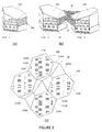
- the tip plate of each module is preferably polygonal. It could be square or rectangular, but it is preferred that it have more than four edges. In particular, as illustrated in Figure 3 , it is preferred that the tip plate be hexagonal -not necessarily regular- comprising two opposite edges which are parallel.
- Two adjacent hexagonal modules would share one of said edge parallel to the opposite edge, such that a straight row can be formed by coupling side by side hexagonal modules by their pairs of opposite, parallel edges as shown in Figures 3(c) &4.
- the edges shared by two adjacent tip plates are not provided with a peripheral wall in order to allow free flow of the glass melt from one module to the next one in the longitudinal direction within one tip plate assembly (1A, 1B).
- the first and second tip plate assemblies (1A, 1B) are each composed of a row of hexagonal tip plate modules coupled side by side by a pair of parallel edges, the two tip plate assemblies being separated by a manifold (2) which floor forms a stiffening rib structure (21).
- the stiffening rib structure has a jagged upper ridge and is composed of flat panels extending from each edge of the hexagonal tip plates facing towards the manifold.
- a corresponding second tip plate (111B) belonging to the second tip plate assembly (1B) also comprises a pair of panels (211B1, 211B2) extending from the two adjacent edges of the tip plate (111B) facing towards the manifold and thus form a V-shaped ridge through which the pairs of panels of the first and second tip plates (111A, 111B) are coupled.
- This multi-faceted stiffening rib not only reinforces the bushing floor against creep but also contributes to a further split of the flow of glass melt before it reaches the two tip plate modules (1A, 1 B), though screens (23A, 23B).
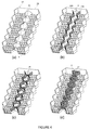
- Figure 4 shows step by step the completion of the distribution manifold (2) which floor is defined by the stiffening rib (21).
- Figure 4(a) shows a bushing assembly comprising a floor composed of two distinct tip plate assemblies (1A, 1B) separated by a stiffening rib (21) comparable (apart from the hexagonal shape of the tip plate modules) to a bushing assembly of the prior art.
- Figure 4 illustrates a bushing assembly composed of hexagonal modules as illustrated in Figure 3(a)
- Figure 4 illustrates a bushing assembly composed of hexagonal modules as illustrated in Figure 3(a)
- the same principle can be applied mutatis mutandis to a bushing assembly comprising first and second substantially rectangular tip plate assemblies (1A, 1B) as illustrated e.g., in Figure 2 .
- the manifold (2) is being built by erecting on either side of the stiffening rib (21) two sets of screens or perforated panels (23A, 23B) jutting out of the bushing assembly floor and defining a volume defined between said two sets of screens and the stiffening rib, forming the floor thereof.
- the screens (23A, 23B) must be perforated to define a flow path between the interior of the manifold (2) and each of the first and second tip plate assemblies (1A, 1B). Additional screens or baffles (25) may be join the first and second sets of screens (23A, 23B) to impose splitting of the flow of melt in the longitudinal direction.
- transverse screens (25) are particularly useful in combination with a stiffening rib (21) having a jagged ridge as illustrated in Figure 4(c) , which drives the flow of molten glass in the longitudinal direction.
- baffles or additional screens (24) (not shown in Figure 4 , but illustrated in Figures 1(b) &2(b) extending in the longitudinal direction and transverse to the first and second set of screens (23A, 23B) can be added to further deviate and split the flow of molten glass.
- the inner volume of the manifold is closed on top with screens (22) defining a flow path from a source of molten glass (3) located upstream of the manifold into the inner volume of the manifold.
- the top of the latter must be closed by a ceiling (12A, 12B), preferably sloped towards the screen (22) to drive the flow of molten glass towards the inlet of the manifold.
- a bushing assembly according to the present invention permits to save considerable precious material compared with a traditional bushing assembly design of same capacity, comprising two rectangular tip plates separated by a rib.
- the preferred embodiment illustrated in Figure 4 with hexagonal tip plates summing 6348 tips requires up to 13% less precious metal and yields 6% less creep than the conventional design.
- the compact and integrated design of the manifold allowing an optimal temperature and composition homogenization of the glass melt in a reduced space and with further economy of material makes such bushing assemblies quite advantageous over the conventional designs.
Landscapes
- Engineering & Computer Science (AREA)
- Chemical & Material Sciences (AREA)
- Life Sciences & Earth Sciences (AREA)
- General Life Sciences & Earth Sciences (AREA)
- Geochemistry & Mineralogy (AREA)
- Manufacturing & Machinery (AREA)
- Materials Engineering (AREA)
- Organic Chemistry (AREA)
- Manufacture, Treatment Of Glass Fibers (AREA)
- Press-Shaping Or Shaping Using Conveyers (AREA)
- Crystals, And After-Treatments Of Crystals (AREA)
Description
- The present invention relates to glass fibre manufacturing equipment. In particular it concerns a bushing assembly providing efficient reinforcement of the tip plates and excellent homogenization of the molten glass with a design permitting to reduce the amount of expensive alloys used for its manufacturing.
- Glass fibres can be produced by melting a glass composition in a melter and drawing them out through the tip plate of a bushing assembly. A bushing assembly is generally in the form of a rectangular box with two pairs of opposite side and end walls forming the perimeter thereof with an opening at the top in fluid communication with the melter. The bottom floor comprises a tip plate which is a plate comprising a multitude of orifices or tips through which the glass melt can flow to form fibres, which are attenuated to reach their desired diameter. To ensure an optimal control of the glass composition and viscosity, the molten glass must be well homogenized and the temperature of the tip plate must be controlled accurately. The temperature of the tip plate depends on the glass melt composition but is generally well above 1000°C. Because of the extreme working conditions, the various components of a bushing assembly are made of platinum or platinum alloys, typically rhodium-platinum alloys. The amounts of such expensive alloys used in the manufacturing of bushing assemblies is therefore of economical concern, even though most of the material can be recycled, since a larger material pool is required at the premises of the bushing manufacturer to ensure a continuous supply of bushing assemblies.
- The load applied on the tip plate is substantial with, on the one hand, the weight of the glass melt lying on top of it and, on the other hand, the drawing force applied to the fibres below. At temperatures well above 1000°C, it is not surprising that tip plates are sensitive to creep and sagging. In order to increase the production rate, larger tip plates are being used which increase the problem of creep and sagging. For this reason, beside the use of transverse gussets distributed along the length of the tip plate, a longitudinal central stiffening rib is often provided in the centre of the floor to stiffen the tip plate in the longitudinal direction; this configuration corresponds to having two tip plates in parallel separated by a longitudinal beam in a single bushing assembly. Usually, the two tip plate portions and the central beam are made of a single plate folded appropriately. The central beam may, however, be welded to the centre of the top surface of a single tip plate or to the longitudinal edges of two separate tip plates. Examples of bushing assemblies comprising a central stiffening rib, dividing the floor of the bushing assembly into two tip plates are disclosed in
WO2000/001630 ,WO2009/128749 ,WO9958460 EP0931026 . - The homogeneity of the glass melt composition and temperature can be improved before it reaches the tip plate(s) by splitting the flow by interposing baffles and perforated screens in the flow path.
US5928402 discloses a multi-screen mixing apparatus for a bushing assembly including a first, upstream screen having openings located at a first portion thereof through which the glass melt must flow and a second, downstream screen having openings located at a second portion thereof offset with respect to the first portion of the upstream screen, such that the molten glass must flow in a non-linear path as it passes through the screens.WO2000/001630 discloses a glass fibre production assembly comprising multiple perforated screens arranged along the flowpath of molten glass from the furnace down to the tip plate, with a diverter (44) arranged just above the bushing assembly and tip plates separated by a central rib. Similarly,WO2009/128749 discloses a glass fibre production assembly with multiple screens laid on the flow path of molten glass from a source of molten glass to two tip plates separated by a central stiffening rib.WO200811298 EP1509478 by a flat screen.US2007/220923 discloses a flow diverter (340) from a furnace and a bushing assembly.US4525188 discloses a bushing assembly wherein molten glass is fed to the tip plates through a plurality of tubular feed inlets through a top cover chamber.US4537609 discloses a bushing assembly provided with a baffle assembly separating a source of molten glass from the tip plate. In all the foregoing bushing assemblies, the features for stiffening the tip plate(s) are distinct from the ones used for homogenizing the glass melt, which results in the use of higher amounts of expensive alloys.EP0931026 discloses a bushing assembly wherein the tip plate is reinforced by a series of adjacent and perforated A-shaped ribs. In this configuration the A-shaped ribs ensure both functions of stiffening the tip plate and splitting the molten glass flow to homogenize the composition and temperature thereof. - The present invention provides a new design for bushing assemblies, allowing an efficient reinforcement of the tip plates and excellent homogenization of the molten glass while reducing the amount of expensive alloys used for its manufacturing. This and other advantages of the present invention are presented in continuation.
- The present invention is defined in the appended independent claims. Preferred embodiments are defined in the dependent claims. In particular, the present invention concerns a bushing assembly comprising:
- (a) a liquid glass feeding unit arranged upstream of, and in fluid communication with,
- (b) a first and second tip plate assemblies extending along a longitudinal direction, arranged side by side, and each surrounded by side walls and end walls and, the first and second tip plate assemblies being separated from one another by a stiffening rib structure extending along said longitudinal direction,
- In a preferred embodiment, each of the separate paths from the manifold to each of the first and second tip plate assemblies comprises a grid or perforated plate through which the liquid glass must flow to reach each tip plate assembly. To enhance even further the homogeneity of the glass melt it is preferred that the glass distribution manifold be in fluid communication with a source of liquid glass located upstream through a grid or perforated plate. The manifold and various screens or perforated plates impose numerous changes in directions to, and splitting of the flow, thus improving the homogeneity in concentration and temperature of the melt. Each of the first and second tip plate assemblies is closed on the top by a ceiling separating the tip plate assembly from the source of liquid glass. It is preferred that said ceiling be sloping towards the grid or perforated plate separating said source from the manifold to force the liquid glass flow down to the manifold.
- The stiffening rib structure separating the two tip plate assemblies and forming the floor of the manifold can have a cross section in the shape of a A or ∩, with the apex or convex side facing the interior of the manifold receiving the liquid glass. No liquid is supposed to flow through the stiffening rib structure. It follows that the stiffening rib structure should preferably be impervious to the liquid glass. It is preferably made of metal and the bottom thereof can be further supported by a core made of refractory material. Additional, metal supports can be coupled to the refractory core to further reinforce the stiffening rib structure.
- The tip plate assemblies comprise a floor formed by a tip plate surrounded by peripheral walls and closed on top by a ceiling. Screens or perforated panels define flow paths towards the manifold. The shape of the tip plate may vary. In one embodiment, each of the first and second tip plate assemblies comprises a single, substantially rectangular tip plate. In an alternative embodiment, each of the first and second tip plate assemblies comprises at least two tip plate modules aligned in fluid communication with each other along the longitudinal direction. Two adjacent modules of a given tip plate assembly are preferably in fluid communication with one another, either through an opening, or through a screen or perforated plate. Each module may comprise a polygonal tip plate. In a preferred embodiment, each tip plate module comprises a polygonal tip plate of more than four edges, preferably of six edges, with two adjacent modules sharing a common edge of said polygon. This configuration enhances the resistance to creep of the tip plate. Creep resistance can be further enhanced by providing a series of parallel stiffening gussets extending substantially normal to the longitudinal direction and mechanically coupled to the tip plates and to at least one side wall adjacent the corresponding tip plates.
- For a fuller understanding of the nature of the present invention, reference is made to the following detailed description taken in conjunction with the accompanying drawings in which:
-
Figure 1 : shows cross sectional views normal to the longitudinal direction of bushing assemblies according to two embodiments of the present invention. -
Figure 2 : shows schematic perspective views of bushing assemblies according to two embodiments of the present invention. -
Figure 3 : shows.(a) a hexagonal tip plate module, (b) a pair of opposite hexagonal tip plate modules of (a) coupled to one another by a manifold, and (c) a view of the stiffening rib structure obtained with hexagonal tip plate modules. -
Figure 4 : shows a bushing assembly according to the present invention comprising several hexagonal tip plate modules as illustrated inFigure 3 , arranged side by side in two rows separated by a stiffening rib structure with addition of successive screens to define a manifold. -
Figure 5 : shows a view of the completed bushing assembly ofFigure 4 . - As illustrated in
Figure 1 and2 , a bushing assembly according to the present invention comprises two tip plate assemblies (1A, 1B) extending along a longitudinal direction, arranged side by side. Each tip assembly (1A, 1B) comprises a floor comprising at least one tip plate (11A, 11B) in the form of a plate comprising tips through which glass fibres are attenuated, said floor being surrounded by side walls and end walls. The top of each tip plate assembly is closed by a ceiling (12A, 12B). The two tip plate assemblies are separated from one another by a stiffening rib structure (21) extending along said longitudinal direction, to reinforce the floor against creep. The stiffening rib structure (21) comprises a stiffening rib, preferably in the shape of a A or ∩, with the apex or convex side facing upstream, with respect to the glass melt flow direction (cf. e.g.,Figure 2(a) &(b)). The stiffening rib can be an integral part of the bushing assembly's floor, which is folded to form a A- or ∩-cross-section as illustrated inFigures 1(b) and2(b) , or it can be distinct from the bushing floor as illustrated inFigures 1(a) &(b). The stiffening rib structure (21) is preferably impervious to the liquid glass. For further reinforcing the tip plates against creep in the direction transverse to the longitudinal direction, a series of parallel stiffening gussets (5) extending substantially normal to the longitudinal direction can be mechanically coupled to the tip plates and to at least one side wall adjacent the corresponding tip plates. - Homogeneity of the glass melt is very important for the quality of the glass fibres thus produced. Screens, grids and baffles are usually interposed in the flow path of the glass melt to force splitting and deviations of the flow. Reinforcement of the bushing floor and homogenization of the glass melt are always achieved with separate means comprising: (a) a stiffening rib and (b) screens or baffles. The separation of these two functions is detrimental to the amount of precious metal required for the manufacturing of a bushing assembly as well as to the size of said bushing assembly. In the present invention, it is proposed for the first time to provide a single element in the form of a glass distribution manifold (2) fulfilling both mechanical and homogenization functions simultaneously. An integral part of the floor of said glass distribution manifold (2) comprises the stiffening rib structure (21). The manifold defines two separate fluid communication paths to the first and second tip plate assemblies (1A, 1B). It is advantageous if each of the separate paths from the manifold to each of the first and second tip plate assemblies comprises a screen, grid or perforated plate (23A, 23B) through which the liquid glass must flow to reach each tip plate assembly. Further splitting of the melt flow can be achieved by bringing the glass distribution manifold (2) in fluid communication with a source (3) of liquid glass located upstream through yet another screen, grid or perforated plate (22). As illustrated in
Figure 1 by the black arrows, with a very compact construction the melt flow is diverted and split abundantly, contributing to bringing glass melt of homogeneous composition and temperature into each tip plate assembly (1A, 1 B) and through the corresponding tip plates (11A, 11 B). Any type of screens, grids, or perforated plates (22, 23A, 23B) can be used to split the melt flow. If required, it is possible to interpose as illustrated inFigures 1(b) and2(b) one or more additional screens or baffles (24) below the top screen (22) to further disrupt the flow. In order to prevent the formation of dead zones upstream from the manifold (2), where no or little flow occurs, the ceilings (12A, 12B) closing the top of the first and second tip plate assemblies (1A, 1B) and separating the tip plate assembly from the source (3) of liquid glass, are preferably sloping towards the grid or perforated plate (22) separating said source (3) from the manifold (2). As illustrated inFigure 1 , the slope of the ceilings (12A, 12B) of the manifold assemblies, which constitute a portion of the floor of the chamber upstream from the manifold, streamlines the flow of molten metal towards the manifold and prevents the formation of dead zones in particular at the corners. - The stiffening rib structure (21) may be reinforced on the outer side thereof by a core (25) made of refractory material as illustrated in
Figure 1(a) . The refractory core can fill the space defined between the first and second tip plate assemblies (1A, 1B) and below the bottom side of the stiffening rib (21). The refractory material core can also be further reinforced by external stiffening metal supports (26) running along the longitudinal direction. - A bushing assembly according to the present invention comprises two tip plate assemblies (1A, 1B) separated by a manifold, which floor is in the shape of a stiffening rib. The first and second tip plate assemblies (1A, 1B) may have different geometries. In one embodiment illustrated in
Figure 2 , each of the first and second tip plate assemblies (1A, 1B) comprises a single, substantially rectangular tip plate (11A, 11B). Such geometry is the closest to traditional bushing assemblies with the drawback that, in spite of the stiffening rib structure (21) and transverse gussets (5), the tip plates (11A, 11B) may still be quite sensitive to creep, especially for large capacity bushing assemblies with tip plates of 6000 or more holes. In an alternative design, each of the first and second tip plate assemblies (1A, 1B) comprises at least two tip plate modules aligned in fluid communication with each other along the longitudinal direction. This permits to reduce the distance from each point of the periphery of a tip plate towards its geometrical centre, which increases its resistance to creep. The tip plate of each module is preferably polygonal. It could be square or rectangular, but it is preferred that it have more than four edges. In particular, as illustrated inFigure 3 , it is preferred that the tip plate be hexagonal -not necessarily regular- comprising two opposite edges which are parallel. Two adjacent hexagonal modules would share one of said edge parallel to the opposite edge, such that a straight row can be formed by coupling side by side hexagonal modules by their pairs of opposite, parallel edges as shown inFigures 3(c) &4. In a preferred embodiment illustrated inFigure 3(a) &(b), the edges shared by two adjacent tip plates are not provided with a peripheral wall in order to allow free flow of the glass melt from one module to the next one in the longitudinal direction within one tip plate assembly (1A, 1B). - In a preferred embodiment illustrated in
Figures 4 &5, the first and second tip plate assemblies (1A, 1B) are each composed of a row of hexagonal tip plate modules coupled side by side by a pair of parallel edges, the two tip plate assemblies being separated by a manifold (2) which floor forms a stiffening rib structure (21). As can be seen inFigure 3(c) , the stiffening rib structure has a jagged upper ridge and is composed of flat panels extending from each edge of the hexagonal tip plates facing towards the manifold. Since two adjacent edges meeting at an apex of a first hexagonal tip plate (111A) face towards the manifold (2), two non-parallel panels (211A1, 211A2) are coupled to said first tip plate and form a concave edge extending from said apex to the ridge of the stiffening rib and thus form a V-shaped ridge. A corresponding second tip plate (111B) belonging to the second tip plate assembly (1B) also comprises a pair of panels (211B1, 211B2) extending from the two adjacent edges of the tip plate (111B) facing towards the manifold and thus form a V-shaped ridge through which the pairs of panels of the first and second tip plates (111A, 111B) are coupled. Coupling side by side in a row several such pairs of first and second tip plates (112A, 112B) yields the floor of a preferred bushing assembly according to the present invention. This multi-faceted stiffening rib not only reinforces the bushing floor against creep but also contributes to a further split of the flow of glass melt before it reaches the two tip plate modules (1A, 1 B), though screens (23A, 23B). -
Figure 4 shows step by step the completion of the distribution manifold (2) which floor is defined by the stiffening rib (21).Figure 4(a) shows a bushing assembly comprising a floor composed of two distinct tip plate assemblies (1A, 1B) separated by a stiffening rib (21) comparable (apart from the hexagonal shape of the tip plate modules) to a bushing assembly of the prior art.. WhenFigure 4 illustrates a bushing assembly composed of hexagonal modules as illustrated inFigure 3(a) , it is clear that the same principle can be applied mutatis mutandis to a bushing assembly comprising first and second substantially rectangular tip plate assemblies (1A, 1B) as illustrated e.g., inFigure 2 . InFigure 4(a) the manifold (2) is being built by erecting on either side of the stiffening rib (21) two sets of screens or perforated panels (23A, 23B) jutting out of the bushing assembly floor and defining a volume defined between said two sets of screens and the stiffening rib, forming the floor thereof. The screens (23A, 23B) must be perforated to define a flow path between the interior of the manifold (2) and each of the first and second tip plate assemblies (1A, 1B). Additional screens or baffles (25) may be join the first and second sets of screens (23A, 23B) to impose splitting of the flow of melt in the longitudinal direction. Such transverse screens (25) are particularly useful in combination with a stiffening rib (21) having a jagged ridge as illustrated inFigure 4(c) , which drives the flow of molten glass in the longitudinal direction. It is clear that at this stage, baffles or additional screens (24) (not shown inFigure 4 , but illustrated inFigures 1(b) &2(b) extending in the longitudinal direction and transverse to the first and second set of screens (23A, 23B) can be added to further deviate and split the flow of molten glass. Finally, the inner volume of the manifold is closed on top with screens (22) defining a flow path from a source of molten glass (3) located upstream of the manifold into the inner volume of the manifold. As illustrated inFigure 5 , in order to force the passage of the glass melt through the manifold whence it will be distributed into the first and second tip plate assemblies (1A, 1B) the top of the latter must be closed by a ceiling (12A, 12B), preferably sloped towards the screen (22) to drive the flow of molten glass towards the inlet of the manifold. - Finite element modelling has revealed that a bushing assembly according to the present invention permits to save considerable precious material compared with a traditional bushing assembly design of same capacity, comprising two rectangular tip plates separated by a rib. In particular, the preferred embodiment illustrated in
Figure 4 with hexagonal tip plates summing 6348 tips requires up to 13% less precious metal and yields 6% less creep than the conventional design. Adding to the superior mechanical properties of a bushing assembly according to the present invention the compact and integrated design of the manifold allowing an optimal temperature and composition homogenization of the glass melt in a reduced space and with further economy of material makes such bushing assemblies quite advantageous over the conventional designs.
Claims (11)
- Bushing assembly comprising:(a) a liquid glass feeding unit arranged upstream of, and in fluid communication with,(b) a first and second tip plate assemblies (1A, 1 B) extending along a longitudinal direction, arranged side by side, and each surrounded by side walls and end walls and, the first and second tip plate assemblies being separated from one another by a stiffening rib structure (21) extending along said longitudinal direction,characterized in that, the feeding unit comprises a glass distribution manifold (2), which defines two separate fluid communication paths to the first and second tip plate assemblies (1A, 1 B), and in that, the stiffening rib structure (21) forms an integral part of the floor of the manifold (2).
- Bushing assembly according to claim 1 wherein each of the separate paths from the manifold to each of the first and second tip plate assemblies comprises a grid or perforated plate (23A, 23B) through which the liquid glass must flow to reach each tip plate assembly.
- Bushing according to any of the preceding claims, wherein the glass distribution manifold (2) is in fluid communication with a source (3) of liquid glass located upstream through a grid or perforated plate (22).
- Bushing according to the preceding claim, wherein each of the first and second tip plate assemblies (1A, 1B) is closed on the top by a ceiling (12A, 12B) separating the tip plate assembly from a source (3) of liquid glass, wherein said ceiling is sloping towards the grid or perforated plate (22) separating said source (3) from the manifold (2).
- Bushing assembly according to any of the preceding claims, wherein the stiffening rib structure (21) has a cross section in the shape of a Λ or ∩, with the apex or convex side facing the interior of the manifold (2) receiving the liquid glass.
- Bushing assembly according to any of the preceding claims, wherein the stiffening rib structure (21) is impervious to the liquid glass.
- Bushing assembly according to any of the preceding claims, wherein each of the first and second tip plate assemblies (1A, 1B) comprises a single, substantially rectangular tip plate (11A, 11B).
- Bushing assembly according to any of claims 1 to 3, wherein each of the first and second tip plate assemblies (1A, 1B) comprises at least two tip plate modules aligned in fluid communication with each other along the longitudinal direction.
- Bushing assembly according to the preceding claim, wherein each tip plate module comprises a polygonal tip plate (111, 112) of more than four edges, two adjacent modules sharing a common edge of said polygon.
- Bushing assembly according to any of the preceding claims, comprising a series of parallel stiffening gussets (5) extending substantially normal to the longitudinal direction and mechanically coupled to the tip plates and to at least one side wall adjacent the corresponding tip plates.
- Bushing according to any of the preceding claims, wherein the portion of the stiffening rib structure (21) forming the floor of the manifold (2) is made of metal and the bottom thereof is supported by a core (25) made of refractory material, said refractory material core preferably comprising further external stiffening metal supports (26).
Priority Applications (1)
| Application Number | Priority Date | Filing Date | Title |
|---|---|---|---|
| EP13723511.5A EP2855379B1 (en) | 2012-05-29 | 2013-05-17 | Bushing assembly comprising a distribution manifold |
Applications Claiming Priority (3)
| Application Number | Priority Date | Filing Date | Title |
|---|---|---|---|
| EP12169809.6A EP2669256A1 (en) | 2012-05-29 | 2012-05-29 | Bushing assembly comprising a distribution manifold |
| PCT/EP2013/060308 WO2013178496A1 (en) | 2012-05-29 | 2013-05-17 | Bushing assembly comprising a distribution manifold |
| EP13723511.5A EP2855379B1 (en) | 2012-05-29 | 2013-05-17 | Bushing assembly comprising a distribution manifold |
Publications (2)
| Publication Number | Publication Date |
|---|---|
| EP2855379A1 EP2855379A1 (en) | 2015-04-08 |
| EP2855379B1 true EP2855379B1 (en) | 2016-10-19 |
Family
ID=48464007
Family Applications (2)
| Application Number | Title | Priority Date | Filing Date |
|---|---|---|---|
| EP12169809.6A Withdrawn EP2669256A1 (en) | 2012-05-29 | 2012-05-29 | Bushing assembly comprising a distribution manifold |
| EP13723511.5A Active EP2855379B1 (en) | 2012-05-29 | 2013-05-17 | Bushing assembly comprising a distribution manifold |
Family Applications Before (1)
| Application Number | Title | Priority Date | Filing Date |
|---|---|---|---|
| EP12169809.6A Withdrawn EP2669256A1 (en) | 2012-05-29 | 2012-05-29 | Bushing assembly comprising a distribution manifold |
Country Status (7)
| Country | Link |
|---|---|
| US (1) | US9573836B2 (en) |
| EP (2) | EP2669256A1 (en) |
| CN (1) | CN104334504B (en) |
| BR (1) | BR112014029128A2 (en) |
| RU (1) | RU2624087C2 (en) |
| TW (1) | TWI577651B (en) |
| WO (1) | WO2013178496A1 (en) |
Families Citing this family (4)
| Publication number | Priority date | Publication date | Assignee | Title |
|---|---|---|---|---|
| EP2676937A1 (en) * | 2012-06-21 | 2013-12-25 | 3B-Fibreglass SPRL | Polygonal tip plate module and bushing assembly comprising such modules. |
| CN104843990B (en) * | 2015-03-24 | 2018-04-24 | 南京航空航天大学 | A kind of energy saving multistage bushing glass furnace device |
| JP7107209B2 (en) * | 2018-12-19 | 2022-07-27 | 日本電気硝子株式会社 | Glass fiber manufacturing method, bushing replacement method, and glass fiber manufacturing device |
| CN110698052B (en) * | 2019-11-22 | 2022-04-26 | 丁胜利 | A wire drawing bushing for basalt fiber processing |
Citations (1)
| Publication number | Priority date | Publication date | Assignee | Title |
|---|---|---|---|---|
| EP2676937A1 (en) * | 2012-06-21 | 2013-12-25 | 3B-Fibreglass SPRL | Polygonal tip plate module and bushing assembly comprising such modules. |
Family Cites Families (20)
| Publication number | Priority date | Publication date | Assignee | Title |
|---|---|---|---|---|
| GB627863A (en) * | 1946-10-01 | 1949-08-17 | Walter Raymond Schlehr | Improvements in and relating to the conditioning of material, especially glass, for the drawing therefrom of fibres |
| SU990698A1 (en) * | 1980-06-16 | 1983-01-23 | Киевская Научно-Исследовательская Лаборатория Базальтового Волокна И Изделий Из Него | Die feeder for making rock fiber |
| DE3111484C2 (en) * | 1981-03-24 | 1983-12-22 | Diether 6203 Hochheim Böttger | Method and device for the production of glass fibers |
| US4525188A (en) | 1983-02-07 | 1985-06-25 | Ppg Industries, Inc. | Fiber forming bushing and method for using same |
| US4537609A (en) | 1984-06-04 | 1985-08-27 | Ppg Industries, Inc. | Stone trap and method of using for making glass fibers |
| US5110333A (en) * | 1990-08-23 | 1992-05-05 | Mccormick Ronald O | Glass fiberizing bushing |
| FR2750980B1 (en) * | 1996-07-12 | 1998-11-06 | Engelhard Clal Sas | BOTTOM OF DIE WITH REPORTED Nipples |
| DE19638056C2 (en) | 1996-09-18 | 2000-07-13 | Bayer Ag | Glass fiber spinning device |
| US5928402A (en) | 1997-08-04 | 1999-07-27 | Owens Corning Fiberglas Technology, Inc. | Multi-screen system for mixing glass flow in a glass bushing |
| RU2125544C1 (en) * | 1997-12-17 | 1999-01-27 | Закрытое акционерное общество "БАЗАЛЬТ" | Spinneret feeder for production of fibers from thermoplastic materials, in particular, from melt of rocks |
| US5948135A (en) | 1998-05-12 | 1999-09-07 | Ppg Industries Ohio, Inc. | Bushing insulation and frame arrangement for making fiber glass |
| US6065310A (en) | 1998-07-01 | 2000-05-23 | Owens Corning Fiberglas Technology, Inc. | High throughput glass fiberizing system and process |
| US6813909B2 (en) * | 2001-06-27 | 2004-11-09 | Owens Corning Fiberglas Technology, Inc. | Reinforcement member for a bushing tip plate and related method |
| US20030221462A1 (en) | 2002-05-31 | 2003-12-04 | Sullivan Timothy A. | Fiber forming bushing assembly having flange support |
| FR2850964B1 (en) * | 2003-02-12 | 2006-06-02 | Saint Gobain Vetrotex | REINFORCING DEVICE FOR A CHAIN DELIVERING FILAMENTS IN PARTICULAR GLASS |
| US20070220923A1 (en) | 2006-03-21 | 2007-09-27 | Oakleaf Anthony P | Melter flow guide for glass fiberizing system |
| RU2315723C1 (en) * | 2006-04-12 | 2008-01-27 | Виктор Данилович Бородин | Spinneret feeder |
| US8027793B2 (en) | 2006-07-10 | 2011-09-27 | Daniel Measurement And Control, Inc. | Method and system of validating data regarding measured hydrocarbon flow |
| US7980099B2 (en) * | 2007-03-15 | 2011-07-19 | Ocv Intellectual Capital, Llc | Multiple alloy bushing assembly |
| RU2369569C1 (en) | 2008-04-18 | 2009-10-10 | Общество с ограниченной ответственностью "Каменный Век" | Method for production of continuous fibre from rocks, installation for its realisation and produced product |
-
2012
- 2012-05-29 EP EP12169809.6A patent/EP2669256A1/en not_active Withdrawn
-
2013
- 2013-05-17 WO PCT/EP2013/060308 patent/WO2013178496A1/en not_active Ceased
- 2013-05-17 BR BR112014029128A patent/BR112014029128A2/en not_active Application Discontinuation
- 2013-05-17 CN CN201380027425.5A patent/CN104334504B/en active Active
- 2013-05-17 US US14/404,760 patent/US9573836B2/en not_active Expired - Fee Related
- 2013-05-17 RU RU2014140677A patent/RU2624087C2/en not_active IP Right Cessation
- 2013-05-17 EP EP13723511.5A patent/EP2855379B1/en active Active
- 2013-05-29 TW TW102118999A patent/TWI577651B/en not_active IP Right Cessation
Patent Citations (1)
| Publication number | Priority date | Publication date | Assignee | Title |
|---|---|---|---|---|
| EP2676937A1 (en) * | 2012-06-21 | 2013-12-25 | 3B-Fibreglass SPRL | Polygonal tip plate module and bushing assembly comprising such modules. |
Also Published As
| Publication number | Publication date |
|---|---|
| EP2669256A1 (en) | 2013-12-04 |
| CN104334504B (en) | 2017-04-12 |
| RU2014140677A (en) | 2016-07-20 |
| US9573836B2 (en) | 2017-02-21 |
| TWI577651B (en) | 2017-04-11 |
| RU2624087C2 (en) | 2017-06-30 |
| TW201410626A (en) | 2014-03-16 |
| WO2013178496A1 (en) | 2013-12-05 |
| CN104334504A (en) | 2015-02-04 |
| BR112014029128A2 (en) | 2017-06-27 |
| EP2855379A1 (en) | 2015-04-08 |
| US20150143853A1 (en) | 2015-05-28 |
Similar Documents
| Publication | Publication Date | Title |
|---|---|---|
| US9573836B2 (en) | Bushing assembly comprising a distribution manifold | |
| CN111196368B (en) | Recirculating vertical wind tunnel | |
| CN101479032B (en) | High throughput thermal blending microreactor apparatus and method | |
| EP2864259B1 (en) | Polygonal tip plate module and bushing assembly comprising such modules | |
| CN104088378A (en) | Encased steel plate and concrete filled steel tube empty and solid combined shear wall | |
| CN205323558U (en) | Cross draw -in groove cage static mixer | |
| CN106013599A (en) | U-shaped steel beam | |
| CN105169786B (en) | Nuclear island safety shell recirculating filter | |
| DE60002880D1 (en) | NOZZLE PLATE SUPPORT IN A SPIDER NOZZLE OF A FIBER DRAWER | |
| CN203452255U (en) | Composite color steel plate and prefabricated house using same | |
| US20140208803A1 (en) | Reinforcing ribs for bushings tip plate | |
| CN220683922U (en) | Multichannel average material changes to material device | |
| JP2004124374A (en) | Concrete slab filling method | |
| CN220270070U (en) | Double-layer furnace end for carbonization furnace and carbonization furnace assembly | |
| JP4699260B2 (en) | Building structure | |
| KR102164351B1 (en) | Stress dispersion type structure | |
| ITMO20000051A1 (en) | MODULAR PREFABRICATED STRUCTURE FOR THE CONSTRUCTION OF INDUSTRIAL AND / OR CIVIL BUILDINGS. | |
| TW201302643A (en) | Reinforcing ribs for bushings tip plate | |
| CN118223612A (en) | Obliquely-installed ALC plate structure and construction method thereof | |
| JP5362893B2 (en) | Unit building | |
| EP0122450A1 (en) | Method and device for dividing melts | |
| CS211780B1 (en) | Working part of glass furnace | |
| JP2013234483A (en) | Beam structure of building |
Legal Events
| Date | Code | Title | Description |
|---|---|---|---|
| PUAI | Public reference made under article 153(3) epc to a published international application that has entered the european phase |
Free format text: ORIGINAL CODE: 0009012 |
|
| 17P | Request for examination filed |
Effective date: 20150105 |
|
| AK | Designated contracting states |
Kind code of ref document: A1 Designated state(s): AL AT BE BG CH CY CZ DE DK EE ES FI FR GB GR HR HU IE IS IT LI LT LU LV MC MK MT NL NO PL PT RO RS SE SI SK SM TR |
|
| AX | Request for extension of the european patent |
Extension state: BA ME |
|
| DAX | Request for extension of the european patent (deleted) | ||
| RIC1 | Information provided on ipc code assigned before grant |
Ipc: C03B 37/08 20060101ALI20160401BHEP Ipc: C03B 37/085 20060101AFI20160401BHEP |
|
| GRAP | Despatch of communication of intention to grant a patent |
Free format text: ORIGINAL CODE: EPIDOSNIGR1 |
|
| INTG | Intention to grant announced |
Effective date: 20160513 |
|
| GRAS | Grant fee paid |
Free format text: ORIGINAL CODE: EPIDOSNIGR3 |
|
| GRAA | (expected) grant |
Free format text: ORIGINAL CODE: 0009210 |
|
| AK | Designated contracting states |
Kind code of ref document: B1 Designated state(s): AL AT BE BG CH CY CZ DE DK EE ES FI FR GB GR HR HU IE IS IT LI LT LU LV MC MK MT NL NO PL PT RO RS SE SI SK SM TR |
|
| REG | Reference to a national code |
Ref country code: GB Ref legal event code: FG4D |
|
| REG | Reference to a national code |
Ref country code: CH Ref legal event code: EP |
|
| REG | Reference to a national code |
Ref country code: AT Ref legal event code: REF Ref document number: 838153 Country of ref document: AT Kind code of ref document: T Effective date: 20161115 |
|
| REG | Reference to a national code |
Ref country code: IE Ref legal event code: FG4D |
|
| REG | Reference to a national code |
Ref country code: DE Ref legal event code: R096 Ref document number: 602013012960 Country of ref document: DE |
|
| REG | Reference to a national code |
Ref country code: NL Ref legal event code: FP |
|
| REG | Reference to a national code |
Ref country code: LT Ref legal event code: MG4D |
|
| PG25 | Lapsed in a contracting state [announced via postgrant information from national office to epo] |
Ref country code: LV Free format text: LAPSE BECAUSE OF FAILURE TO SUBMIT A TRANSLATION OF THE DESCRIPTION OR TO PAY THE FEE WITHIN THE PRESCRIBED TIME-LIMIT Effective date: 20161019 |
|
| REG | Reference to a national code |
Ref country code: AT Ref legal event code: MK05 Ref document number: 838153 Country of ref document: AT Kind code of ref document: T Effective date: 20161019 |
|
| PG25 | Lapsed in a contracting state [announced via postgrant information from national office to epo] |
Ref country code: NO Free format text: LAPSE BECAUSE OF FAILURE TO SUBMIT A TRANSLATION OF THE DESCRIPTION OR TO PAY THE FEE WITHIN THE PRESCRIBED TIME-LIMIT Effective date: 20170119 Ref country code: LT Free format text: LAPSE BECAUSE OF FAILURE TO SUBMIT A TRANSLATION OF THE DESCRIPTION OR TO PAY THE FEE WITHIN THE PRESCRIBED TIME-LIMIT Effective date: 20161019 Ref country code: SE Free format text: LAPSE BECAUSE OF FAILURE TO SUBMIT A TRANSLATION OF THE DESCRIPTION OR TO PAY THE FEE WITHIN THE PRESCRIBED TIME-LIMIT Effective date: 20161019 Ref country code: GR Free format text: LAPSE BECAUSE OF FAILURE TO SUBMIT A TRANSLATION OF THE DESCRIPTION OR TO PAY THE FEE WITHIN THE PRESCRIBED TIME-LIMIT Effective date: 20170120 |
|
| REG | Reference to a national code |
Ref country code: FR Ref legal event code: PLFP Year of fee payment: 5 |
|
| PG25 | Lapsed in a contracting state [announced via postgrant information from national office to epo] |
Ref country code: IS Free format text: LAPSE BECAUSE OF FAILURE TO SUBMIT A TRANSLATION OF THE DESCRIPTION OR TO PAY THE FEE WITHIN THE PRESCRIBED TIME-LIMIT Effective date: 20170219 Ref country code: HR Free format text: LAPSE BECAUSE OF FAILURE TO SUBMIT A TRANSLATION OF THE DESCRIPTION OR TO PAY THE FEE WITHIN THE PRESCRIBED TIME-LIMIT Effective date: 20161019 Ref country code: RS Free format text: LAPSE BECAUSE OF FAILURE TO SUBMIT A TRANSLATION OF THE DESCRIPTION OR TO PAY THE FEE WITHIN THE PRESCRIBED TIME-LIMIT Effective date: 20161019 Ref country code: AT Free format text: LAPSE BECAUSE OF FAILURE TO SUBMIT A TRANSLATION OF THE DESCRIPTION OR TO PAY THE FEE WITHIN THE PRESCRIBED TIME-LIMIT Effective date: 20161019 Ref country code: PT Free format text: LAPSE BECAUSE OF FAILURE TO SUBMIT A TRANSLATION OF THE DESCRIPTION OR TO PAY THE FEE WITHIN THE PRESCRIBED TIME-LIMIT Effective date: 20170220 Ref country code: PL Free format text: LAPSE BECAUSE OF FAILURE TO SUBMIT A TRANSLATION OF THE DESCRIPTION OR TO PAY THE FEE WITHIN THE PRESCRIBED TIME-LIMIT Effective date: 20161019 Ref country code: ES Free format text: LAPSE BECAUSE OF FAILURE TO SUBMIT A TRANSLATION OF THE DESCRIPTION OR TO PAY THE FEE WITHIN THE PRESCRIBED TIME-LIMIT Effective date: 20161019 Ref country code: FI Free format text: LAPSE BECAUSE OF FAILURE TO SUBMIT A TRANSLATION OF THE DESCRIPTION OR TO PAY THE FEE WITHIN THE PRESCRIBED TIME-LIMIT Effective date: 20161019 |
|
| REG | Reference to a national code |
Ref country code: DE Ref legal event code: R097 Ref document number: 602013012960 Country of ref document: DE |
|
| PG25 | Lapsed in a contracting state [announced via postgrant information from national office to epo] |
Ref country code: RO Free format text: LAPSE BECAUSE OF FAILURE TO SUBMIT A TRANSLATION OF THE DESCRIPTION OR TO PAY THE FEE WITHIN THE PRESCRIBED TIME-LIMIT Effective date: 20161019 Ref country code: SK Free format text: LAPSE BECAUSE OF FAILURE TO SUBMIT A TRANSLATION OF THE DESCRIPTION OR TO PAY THE FEE WITHIN THE PRESCRIBED TIME-LIMIT Effective date: 20161019 Ref country code: CZ Free format text: LAPSE BECAUSE OF FAILURE TO SUBMIT A TRANSLATION OF THE DESCRIPTION OR TO PAY THE FEE WITHIN THE PRESCRIBED TIME-LIMIT Effective date: 20161019 Ref country code: DK Free format text: LAPSE BECAUSE OF FAILURE TO SUBMIT A TRANSLATION OF THE DESCRIPTION OR TO PAY THE FEE WITHIN THE PRESCRIBED TIME-LIMIT Effective date: 20161019 Ref country code: EE Free format text: LAPSE BECAUSE OF FAILURE TO SUBMIT A TRANSLATION OF THE DESCRIPTION OR TO PAY THE FEE WITHIN THE PRESCRIBED TIME-LIMIT Effective date: 20161019 |
|
| PLBE | No opposition filed within time limit |
Free format text: ORIGINAL CODE: 0009261 |
|
| STAA | Information on the status of an ep patent application or granted ep patent |
Free format text: STATUS: NO OPPOSITION FILED WITHIN TIME LIMIT |
|
| PG25 | Lapsed in a contracting state [announced via postgrant information from national office to epo] |
Ref country code: BG Free format text: LAPSE BECAUSE OF FAILURE TO SUBMIT A TRANSLATION OF THE DESCRIPTION OR TO PAY THE FEE WITHIN THE PRESCRIBED TIME-LIMIT Effective date: 20170119 Ref country code: IT Free format text: LAPSE BECAUSE OF FAILURE TO SUBMIT A TRANSLATION OF THE DESCRIPTION OR TO PAY THE FEE WITHIN THE PRESCRIBED TIME-LIMIT Effective date: 20161019 Ref country code: SM Free format text: LAPSE BECAUSE OF FAILURE TO SUBMIT A TRANSLATION OF THE DESCRIPTION OR TO PAY THE FEE WITHIN THE PRESCRIBED TIME-LIMIT Effective date: 20161019 Ref country code: LU Free format text: LAPSE BECAUSE OF NON-PAYMENT OF DUE FEES Effective date: 20170531 |
|
| 26N | No opposition filed |
Effective date: 20170720 |
|
| PG25 | Lapsed in a contracting state [announced via postgrant information from national office to epo] |
Ref country code: SI Free format text: LAPSE BECAUSE OF FAILURE TO SUBMIT A TRANSLATION OF THE DESCRIPTION OR TO PAY THE FEE WITHIN THE PRESCRIBED TIME-LIMIT Effective date: 20161019 |
|
| REG | Reference to a national code |
Ref country code: CH Ref legal event code: PL |
|
| GBPC | Gb: european patent ceased through non-payment of renewal fee |
Effective date: 20170517 |
|
| PG25 | Lapsed in a contracting state [announced via postgrant information from national office to epo] |
Ref country code: MC Free format text: LAPSE BECAUSE OF FAILURE TO SUBMIT A TRANSLATION OF THE DESCRIPTION OR TO PAY THE FEE WITHIN THE PRESCRIBED TIME-LIMIT Effective date: 20161019 |
|
| REG | Reference to a national code |
Ref country code: IE Ref legal event code: MM4A |
|
| PG25 | Lapsed in a contracting state [announced via postgrant information from national office to epo] |
Ref country code: LI Free format text: LAPSE BECAUSE OF NON-PAYMENT OF DUE FEES Effective date: 20170531 Ref country code: CH Free format text: LAPSE BECAUSE OF NON-PAYMENT OF DUE FEES Effective date: 20170531 |
|
| PG25 | Lapsed in a contracting state [announced via postgrant information from national office to epo] |
Ref country code: LU Free format text: LAPSE BECAUSE OF NON-PAYMENT OF DUE FEES Effective date: 20170517 |
|
| PG25 | Lapsed in a contracting state [announced via postgrant information from national office to epo] |
Ref country code: IE Free format text: LAPSE BECAUSE OF NON-PAYMENT OF DUE FEES Effective date: 20170517 Ref country code: GB Free format text: LAPSE BECAUSE OF NON-PAYMENT OF DUE FEES Effective date: 20170517 |
|
| REG | Reference to a national code |
Ref country code: FR Ref legal event code: PLFP Year of fee payment: 6 |
|
| PGFP | Annual fee paid to national office [announced via postgrant information from national office to epo] |
Ref country code: DE Payment date: 20180522 Year of fee payment: 6 |
|
| PG25 | Lapsed in a contracting state [announced via postgrant information from national office to epo] |
Ref country code: MT Free format text: LAPSE BECAUSE OF NON-PAYMENT OF DUE FEES Effective date: 20170517 |
|
| PG25 | Lapsed in a contracting state [announced via postgrant information from national office to epo] |
Ref country code: HU Free format text: LAPSE BECAUSE OF FAILURE TO SUBMIT A TRANSLATION OF THE DESCRIPTION OR TO PAY THE FEE WITHIN THE PRESCRIBED TIME-LIMIT; INVALID AB INITIO Effective date: 20130517 |
|
| PGFP | Annual fee paid to national office [announced via postgrant information from national office to epo] |
Ref country code: FR Payment date: 20190523 Year of fee payment: 7 |
|
| PG25 | Lapsed in a contracting state [announced via postgrant information from national office to epo] |
Ref country code: CY Free format text: LAPSE BECAUSE OF FAILURE TO SUBMIT A TRANSLATION OF THE DESCRIPTION OR TO PAY THE FEE WITHIN THE PRESCRIBED TIME-LIMIT Effective date: 20161019 |
|
| PG25 | Lapsed in a contracting state [announced via postgrant information from national office to epo] |
Ref country code: MK Free format text: LAPSE BECAUSE OF FAILURE TO SUBMIT A TRANSLATION OF THE DESCRIPTION OR TO PAY THE FEE WITHIN THE PRESCRIBED TIME-LIMIT Effective date: 20161019 |
|
| REG | Reference to a national code |
Ref country code: DE Ref legal event code: R119 Ref document number: 602013012960 Country of ref document: DE |
|
| PG25 | Lapsed in a contracting state [announced via postgrant information from national office to epo] |
Ref country code: TR Free format text: LAPSE BECAUSE OF FAILURE TO SUBMIT A TRANSLATION OF THE DESCRIPTION OR TO PAY THE FEE WITHIN THE PRESCRIBED TIME-LIMIT Effective date: 20161019 |
|
| PG25 | Lapsed in a contracting state [announced via postgrant information from national office to epo] |
Ref country code: DE Free format text: LAPSE BECAUSE OF NON-PAYMENT OF DUE FEES Effective date: 20191203 |
|
| PG25 | Lapsed in a contracting state [announced via postgrant information from national office to epo] |
Ref country code: AL Free format text: LAPSE BECAUSE OF FAILURE TO SUBMIT A TRANSLATION OF THE DESCRIPTION OR TO PAY THE FEE WITHIN THE PRESCRIBED TIME-LIMIT Effective date: 20161019 |
|
| PG25 | Lapsed in a contracting state [announced via postgrant information from national office to epo] |
Ref country code: FR Free format text: LAPSE BECAUSE OF NON-PAYMENT OF DUE FEES Effective date: 20200531 |
|
| PGFP | Annual fee paid to national office [announced via postgrant information from national office to epo] |
Ref country code: NL Payment date: 20250926 Year of fee payment: 13 |
|
| PGFP | Annual fee paid to national office [announced via postgrant information from national office to epo] |
Ref country code: BE Payment date: 20250929 Year of fee payment: 13 |