EP2855270B1 - Aircraft seat having a seat substructure - Google Patents
Aircraft seat having a seat substructure Download PDFInfo
- Publication number
- EP2855270B1 EP2855270B1 EP13725571.7A EP13725571A EP2855270B1 EP 2855270 B1 EP2855270 B1 EP 2855270B1 EP 13725571 A EP13725571 A EP 13725571A EP 2855270 B1 EP2855270 B1 EP 2855270B1
- Authority
- EP
- European Patent Office
- Prior art keywords
- seat
- aircraft
- seat base
- base
- aircraft seat
- Prior art date
- Legal status (The legal status is an assumption and is not a legal conclusion. Google has not performed a legal analysis and makes no representation as to the accuracy of the status listed.)
- Active
Links
Images

Classifications
-
- B—PERFORMING OPERATIONS; TRANSPORTING
- B64—AIRCRAFT; AVIATION; COSMONAUTICS
- B64D—EQUIPMENT FOR FITTING IN OR TO AIRCRAFT; FLIGHT SUITS; PARACHUTES; ARRANGEMENTS OR MOUNTING OF POWER PLANTS OR PROPULSION TRANSMISSIONS IN AIRCRAFT
- B64D11/00—Passenger or crew accommodation; Flight-deck installations not otherwise provided for
- B64D11/06—Arrangements of seats, or adaptations or details specially adapted for aircraft seats
- B64D11/0619—Arrangements of seats, or adaptations or details specially adapted for aircraft seats with energy absorbing means specially adapted for mitigating impact loads for passenger seats, e.g. at a crash
-
- B—PERFORMING OPERATIONS; TRANSPORTING
- B64—AIRCRAFT; AVIATION; COSMONAUTICS
- B64D—EQUIPMENT FOR FITTING IN OR TO AIRCRAFT; FLIGHT SUITS; PARACHUTES; ARRANGEMENTS OR MOUNTING OF POWER PLANTS OR PROPULSION TRANSMISSIONS IN AIRCRAFT
- B64D11/00—Passenger or crew accommodation; Flight-deck installations not otherwise provided for
- B64D11/06—Arrangements of seats, or adaptations or details specially adapted for aircraft seats
- B64D11/0649—Seats characterised by special features for reducing weight
-
- Y—GENERAL TAGGING OF NEW TECHNOLOGICAL DEVELOPMENTS; GENERAL TAGGING OF CROSS-SECTIONAL TECHNOLOGIES SPANNING OVER SEVERAL SECTIONS OF THE IPC; TECHNICAL SUBJECTS COVERED BY FORMER USPC CROSS-REFERENCE ART COLLECTIONS [XRACs] AND DIGESTS
- Y02—TECHNOLOGIES OR APPLICATIONS FOR MITIGATION OR ADAPTATION AGAINST CLIMATE CHANGE
- Y02T—CLIMATE CHANGE MITIGATION TECHNOLOGIES RELATED TO TRANSPORTATION
- Y02T50/00—Aeronautics or air transport
- Y02T50/40—Weight reduction
Definitions
- the invention relates to an aircraft seat with a seat base, the seat base being attachable to a seat unit of the aircraft seat on a first side.
- Aircraft seats for passenger cabins are typically attached to the floor structure of the aircraft.
- the relevant authorities have formulated various requirements which are intended to ensure the safety of the passenger on the aircraft seat in different situations.
- Seat substructures of aircraft seats are known from the prior art, which have a metallic seat frame as a force-transmitting element.
- the seat frame has a truss structure.
- An aluminum alloy is typically used as the material.
- the aircraft seat offers a possibility of limiting the forces acting on the passenger by absorbing kinetic energy.
- the rigidity of the seat substructure is designed so that the forces acting on the seated passenger in a crash are limited by the deformation of the seat substructure.
- the plastic deformation to absorb the kinetic energy is distributed over the seat base by the load-bearing structure Structure.
- the distributed deformation over the seat substructure results in an equivalent to a rotation of the seat about a virtual pivot point near the floor of the aircraft cabin.
- the resulting rotation leads to a clear translational shift in the upper area of the aircraft seat and thus to a larger movement envelope, which must be kept free as free space from other components in order to prevent collisions between the aircraft seat and the passenger with the other components.
- the metallic truss structure has large dimensions and, due to the necessary plastic deformability, offers little potential for weight reduction.
- a seat device for an aircraft which has a shell structure, which is used to attach the seat device to a floor structure.
- the WO 2006/124555 A2 shows an energy absorbing fastening device which is arranged directly on the aircraft-fixed seat rail.
- the seat is fastened at two rear locations via an assembly that enables a rotational movement in the area of the seat rail in the event of a crash.
- the attachment to the seat rail takes place via a bolt which is attached to the seat via a bolt assembly.
- This bolt assembly is designed to release the bolt in a longitudinal direction with energy dissipation when a tensile force acting on the bolt is exceeded.
- a seat frame which has a carrier which connects two parts of the seat frame to one another, the carrier being formed by a hollow body.
- the US 2005/0140193 A1 discloses a passenger seat for a vehicle, the actual seat being held by a rigid shell component.
- the shell component is connected via a main strut to leg elements, which in turn are connected to the floor of the vehicle.
- the object of the invention is to provide an aircraft seat which enables the lowest possible movement envelope.
- An aircraft seat with a seat base is proposed, the seat base on a first side on a seat unit of the aircraft seat is attachable.
- the seat substructure can be fastened on a second side for aircraft-fixed attachment to a floor connection assembly, the seat substructure being formed by at least one rigid shell component, a means for limiting the force being provided above the seat substructure being provided, the means for limiting the force to protect the overloading of a passenger in the event of a crash it is provided by the limitation of forces which act on the aircraft seat in the ground plane.
- the design of the seat substructure with at least one rigid shell component leads overall to a very rigid seat substructure for the seat substructure compared to the prior art.
- the seat substructure is very stiff due to the construction, in particular in the direction of bending, ie with respect to forces acting on the plane seat at the floor level, so that in the event of a crash, the first side of the seat substructure, which is directed toward the seat surface of the aircraft seat, has the least possible displacement or deformation in the floor level opposite the second side of the seat base.
- the mechanical connection to the floor connection assembly preferably also has a corresponding rigidity.
- the shell construction enables a very light construction with a correspondingly high rigidity.
- the seat substructure causes the aircraft seat to undergo a significantly reduced rotation around a rotation center, the rotation center also being displaced in the direction of the seat surface by the rigid seat substructure.
- the seat base is therefore not intended to absorb kinetic energy due to accelerations in the floor level.
- the seat base is dimensionally stable in the event of a crash.
- the dimensionally stable design of the seat substructure with a rigid construction which is necessary for the displacement of the pivot point or center of rotation of the aircraft seat towards the seat surface, can therefore be a pre-deformation of the floor structure of the aircraft cabin, which can occur before the actual crash, and mapped by corresponding official requirements won't follow alone.
- the seat substructure is therefore fastened to the floor structure by means of a floor connection assembly, so that the seat substructure is not burdened by pre-deformation of the floor structure.
- the force limitation of forces acting in the floor level to protect the overload of the passenger in the event of a crash is carried out above the seat substructure by means provided for this purpose.
- the aircraft seat therefore preferably has a functional separation of load-bearing and energy-absorbing structures.
- the structural design of the seat substructure can be based on a rigid, dimensionally stable structure of the seat substructure, without any intended deformation for energy absorption in the event of a crash.
- the other means for energy absorption in the event of a crash can functionally limit the force.
- the load-bearing structure of the aircraft seat can therefore be designed precisely, so that the aircraft seat, in particular the seat substructure, can be greatly reduced in weight.
- the seat base can be made narrower, so that the seat base does not protrude when the seat is rotated.
- the base of the seat base can be made smaller than the seat surface arranged above it.
- the shell construction can be seen as a flat structure with load-bearing effect and can be distinguished from simple cladding of the seat substructure.
- the seat base is preferably a surface component, also referred to as a non-truss.
- aircraft-fixed refers to the mechanical connection to the main structures of the aircraft in which the aircraft seat is arranged, in particular to the floor structure of the cabin floor of the aircraft.
- the shell component is curved at least in one direction.
- the curvature is particularly advantageous for the bending and buckling stiffness of the seat substructure, so that overall a high stiffness of the seat substructure can be achieved.
- the seat substructure is preferably cylindrical or conical. This shape of the seat substructure leads to a columnar structure for the seat substructure, which in addition to mechanical aspects also offers aesthetic advantages.
- the seat substructure is preferably conical in order to achieve greater buckling stability.
- the difference in the mean diameter of the first and second sides of the seat substructure is preferably between 10 mm and 100 mm, preferably 30 mm.
- the seat substructure preferably has a circular or elliptical cross section.
- Such a cross section is advantageous for a light and rigid structure.
- the ratio of the major axis to the minor axis of the cross section is preferably between 1: 1 to 2: 1.
- the seat substructure has a closed profile in at least one cross section to the vertical axis.
- a closed profile is advantageous for the force curve and thus for the stability and strength of the seat base.
- the seat substructure has a closed profile over its entire height or over a substantial part of its height.
- the seat substructure is advantageously a closed hollow body.
- the closed hollow body can have individual openings, in particular on the first and the second side.
- the seat base has hand holes of the same dimensions on two opposite sides.
- the hand holes can be used for assembly and maintenance purposes, for example to gain access to the mechanical connection elements on the first and second sides of the seat base.
- the version with two hand holes on opposite sides maintains the symmetry of the seat substructure, which prevents unwanted evasive movements of the structure in the event of large loads in the event of a crash.
- hand holes are preferably dimensioned the same, although small size, shape and position differences between the hand holes are still possible.
- the hand holes are preferably arranged on the side, the side being primarily related to the flight direction of the aircraft.
- the hand holes are outside the area of the seat base that is heavily loaded in the typical crash event.
- the seat substructure preferably has at least one vertical crash element and / or a vertical deformation section.
- the vertical crash element or a correspondingly acting deformation section absorbs kinetic energy in this direction and thereby limits the forces acting on the passenger.
- the explicit provision of a crash element is advantageous in order to maintain the rigidity of the seat substructure and at the same time to achieve a force limitation.
- the cushion masses on the seat surface can be kept comparatively thin by a corresponding vertical crash element, since the cushion masses do not have to have any force-limiting effect in the event of a crash. This reduces the fire load on the aircraft seat.
- a vertical crash element can be made significantly lighter and better designed than an equivalent-looking thickening of the seat upholstery. Furthermore, this can be advantageous in relation to the necessary overall height.
- the seat substructure can advantageously be fastened to a seat unit via a rotating element.
- the turntable enables improved use of the aircraft seat, for example in an arrangement with tables for improved standing up or for alignment during meetings or conferences.
- the turntable is aligned for take-off, landing and taxiing, preferably for the seated person in the aircraft direction forwards or backwards.
- the seat substructure can be attached to the floor connection assembly via a rotating element.
- the seat substructure preferably has a translation unit on the first and / or the second side.
- a translation unit enables a relative movement between the seat substructure and a floor connection assembly and / or a seat unit, so that the aircraft seat can be translated by a passenger in the plane of the cabin floor.
- the seat unit and the floor connection module can be attached to the seat substructure via the translation unit.
- the translation unit is advantageously blocked in a basic position, so that no relative movement is possible, the basic position being able to be lifted by a seated person, for example in order to be able to move closer to a possible table.
- the seat base has a cavity for receiving at least one electrical device or a functional object.
- Electrical devices e.g. Electrical control units for the seat adjustment or on-board entertainment systems can be arranged in an advantageous manner in the seat substructure, since the seat substructure, which is preferably closed off from the outside, provides mechanical protection against manipulation by the passengers for the corresponding devices, which is only possible, for example, in the case of a truss structure for a seat substructure Housing or cladding is possible.
- Functional objects that can possibly be removed via the hand holes can be life jackets or pillows, for example.
- functional objects can be mechanical arrangements which, for example, enable the seat to be adjusted.
- the seat base is preferably a fiber-reinforced component.
- a fiber-reinforced structure of the seat substructure is particularly suitable for a carbon fiber-reinforced structure a high rigidity of the seat substructure is advantageous.
- a shell component can advantageously be made using a fiber-reinforced component.
- the seat base has a wound fiber structure.
- the wound fiber structure is advantageous due to the typical shape of the seat substructure, since it allows simple manufacture of tubular structures. Furthermore, only parts of the structure can be wound that are supplemented, for example, by additional fiber layers, in particular before the matrix material of the fiber composite cures.
- the seat substructure preferably has a metallic ring on the upper and / or lower edge of the shell component.
- this ring is glued to the shell component of the seat substructure.
- other forms of fastening, such as rivets, are also possible.
- the metallic ring enables a simple mechanical connection of the seat base on the first side to the seat unit and / or on the second side to a floor connection assembly. In this way, the seat substructure, in particular in the case of a fiber-reinforced shell component, can easily be connected to the other parts of the aircraft seat, e.g. by screwing.
- the aircraft seat has a floor connection assembly, the seat substructure and at least a part of the floor connection assembly being an integral component. This enables an improved flow of power from the floor connection assembly to the seat substructure. Furthermore, no mechanical elements are required to establish the connection in the seat substructure and in the floor connection assembly, which reduces the weight of the aircraft seat.
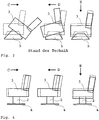
- FIG. 1 An embodiment of an aircraft seat 1 with a seat substructure 2 is shown.
- the seat base 2 is on a first side, in Fig. 1 shown at the upper end of the seat substructure 2, fastened with a seat unit 3 of the aircraft seat 1.
- the seat unit 3 comprises a seat base 6, a seat surface 7 and a backrest assembly 8.
- the seat substructure 2 can be fastened to a seat base 6 of the aircraft seat 1.
- Fig. 1 Shown at the lower end of the seat base 2, the seat base 2 is attached to a floor connection assembly 4.
- a rigid mechanical connection between the seat substructure 2 and the floor structure of an aircraft can be produced with the floor connection assembly 4.
- the seat substructure 2 establishes the mechanical connection between the floor connection assembly 4 and the seat unit 3.
- the seat substructure 2 is designed to be very stiff, so that crash loads in a direction of the floor plane only lead to slight displacements on the first side of the seat substructure 4, as a result of which rotation or tilting of the aircraft seat 1 is largely prevented.
- the seat substructure 2 has an elliptical cross section and the shape of a conical section, so that the cross-sectional areas of the seat substructure 2 on the first and second sides are different in size.
- the basic structure of the seat base 2 is a rigid shell component, which in this exemplary embodiment is curved in the circumferential direction. The bending stiffness of the seat substructure 2 can thereby be improved and can be designed such that the seat substructure 2 executes as little translational movement as possible on its first side parallel to the floor level in the event of a crash.
- the seat substructure 2 can primarily determine the seat height of the aircraft seat 1. Different seat heights with different height substructures 2 can be achieved.
- the height of the seat substructure 2 of the aircraft seat 1 is between 20 cm and 60 cm. The advantageous height in this embodiment is 30 cm.
- a rigid seat substructure 2 can largely transmit the corresponding forces to crash elements for energy absorption, which are arranged above the seat substructure 2 and are provided specifically for force limitation and for absorbing kinetic energy, without their own deformation.
- the energy absorption in the event of a crash and the paths required for this can be shifted with the rigid seat substructure 2 into the area of the seat unit 3, where the movements for energy absorption can be realized without secondary movement and / or rotations.
- the crash elements can allow a corresponding force-limited flexibility in the load direction from the crash, the crash elements being deformed and / or destroyed while absorbing energy. This applies in particular to loads or high accelerations from a crash that are largely aligned parallel to the floor level of the cabin of the aircraft.
- a vertical crash element is provided in or on the seat base 2, which is in the transition or in the connection area to a seat unit 3 limits the transmitted forces and for this purpose enables a force-limited relative movement between the seat base 2 and the seat unit 3 in the direction of the vertical axis H. This limits the loads acting on the passenger and on the mechanical structure, as a result of which injuries to the passenger and structural failure on parts of the aircraft seat 1 can be avoided.
- the vertical crash element can be arranged below a turntable for connection to a seat unit 3 in the load path.
- the vertical crash element for example mechanical foams made of polymers or metals, fiber composite structures and / or metallic structures can be used which are compressed in the event of a crash while absorbing energy.
- the vertical crash elements are provided for a one-off crash, as a result of which the corresponding costs and weight can be kept low.
- the aircraft seat 1 with the seat substructure 2 enables a slim construction of the aircraft seat 1 and a closer arrangement of individual comfortable aircraft seats 1 in the cabin of an aircraft.
- the seat substructure 2 does not protrude under the seat surface 7 when the aircraft seat 1 rotates due to its slim design.
- the electrical switch boxes which enable different functionalities of the aircraft seat 1, are arranged in the seat substructure 2.
- the seat substructure 2 which offers a corresponding installation space which is mechanically protected and is only subjected to minor deformations in the crash. Therefore, the electrical switch boxes or devices can be advantageously arranged here.
- the usual arrangement of such devices is for example in the armrests 9, which can be made very slim and light in this way.
- the seat base 2 can be used to hold a functional object, such as pneumatic systems and / or valves, drives with control cables and / or cable harnesses.
- a functional object such as pneumatic systems and / or valves, drives with control cables and / or cable harnesses.
- the functional object is stored in a cavity of the seat substructure 2 on provided holders and / or receptacles. In dependence of The holders can be adapted to the functional object to the intended object.
- a seat substructure 2 is shown in a single illustration.
- the seat base 2 has an elliptical shape with a ratio of the main axis to the secondary axis of the cross section of between 1: 1.1.
- the average diameter of the cross-sectional area is 30 mm smaller on the first side than on the second side, which is shown in FIG Fig. 2 is covered.
- the height of the seat base 2 along the vertical axis H is 300 mm in this exemplary embodiment.
- FIG. 3 An aircraft seat 1 from the prior art is shown with a seat frame 5.
- the aircraft seat 1 from the prior art with its deformation behavior after three possible crashes with different acceleration directions C, D, E of the center of gravity of a seated passenger, is in Fig. 3 not shown.
- the official requirements for aircraft seats 1 include that in the event of a crash, a pre-deformation of the aircraft floor must be assumed, which must be taken up or endured by the seat frame 5. Therefore, the seat frame 5 is designed to be plastically deformable for receiving the pre-deformation. This applies in particular to the lower part. In addition to the pre-deformation, the seat frame 5 also absorbs the loads in the event of a crash with high accelerations. The forces acting on a seated passenger are limited by the flexible structure of the seat frame 5. Overall, a comparatively large deformation occurs in the lower region of the aircraft seat 1, which increases rotation of the aircraft seat 1, the pivot point being low in relation to the seat surface of the aircraft seat 1, which leads to large deflections in the upper region of the aircraft seat 1.
- the deflection in the event of a crash defines the envelope of movement of the aircraft seat 1 and the seated passenger, which must be kept free of objects and / or objects in the cabin of the aircraft. According to the prior art, there is a correspondingly large envelope of movement. According to the prior art, a more rigid design of the seat frame 5 is not possible due to the necessary absorption of pre-deformations of the floor structure of the aircraft by the seat frame 5 and the required force limitation for the passenger by absorbing kinetic energy in the event of a crash.
- FIG. 4 Three aircraft seats 1 are shown with an exemplary embodiment of a floor connection assembly 4, which experience the same accelerations from different crashes as the aircraft seats 1 in FIG Fig. 3 ,
- the floor connection assembly 4 does not forward pre-deformations of the floor structure of the aircraft to the seat substructure 2. Therefore, the seat base 2 does not have to be able to absorb deformations and can be made very stiff. Furthermore, the use of light and rigid materials with low deformation potential, such as, for example, carbon fiber reinforced plastics, is made possible, which can lead to a lighter aircraft seat 1.
- the rigid design of the seat base 2 offers various advantages in the event of a crash, for example a rotational movement of the aircraft seat 1 in the event of a crash with acceleration directions in the ground plane C, D can be largely suppressed and / or the energy absorption or force limitation take place specifically above the seat base 2, which can enable a small movement envelope and a lower structural load on the aircraft seat 1 in the event of a crash.
Description
Die Erfindung betrifft einen Flugzeugsitz mit einem Sitzunterbau, wobei der Sitzunterbau an einer ersten Seite an einer Sitzeinheit des Flugzeugsitzes befestigbar ist.The invention relates to an aircraft seat with a seat base, the seat base being attachable to a seat unit of the aircraft seat on a first side.
Flugzeugsitze für Passagierkabinen werden typischerweise an der Bodenstruktur des Flugzeugs befestigt. Für eine sichere Verwendung des Flugzeugsitzes im Luftverkehrsbetrieb werden durch die entsprechenden Behörden verschiedene Anforderungen formuliert, die die Sicherheit des Passagiers auf dem Flugzeugsitz in verschiedenen Situationen sicherstellen sollen.Aircraft seats for passenger cabins are typically attached to the floor structure of the aircraft. For the safe use of the aircraft seat in air traffic operations, the relevant authorities have formulated various requirements which are intended to ensure the safety of the passenger on the aircraft seat in different situations.
Aus dem Stand der Technik sind Sitzunterbauten von Flugzeugsitzen bekannt, die ein metallisches Sitzgestell als kraftübertragendes Element aufweisen. In der Regel weist das Sitzgestell eine Fachwerkstruktur auf. Als Material wird typischerweise eine Aluminiumlegierung verwendet. Für einen Crashfall besteht die Anforderung, dass die dynamische Insassenbelastung unter definierten Bedingungen nicht überschritten wird. Hierfür ist es notwendig, dass der Flugzeugsitz eine Möglichkeit bietet, die auf den Passagier einwirkenden Kräfte durch Aufnahme kinetischer Energie zu begrenzen. Die Steifigkeit des Sitzunterbaus wird konstruktiv so ausgelegt, dass die auf den sitzenden Passagier auftretenden Kräfte in einem Crashfall durch die Verformung des Sitzunterbaus begrenzt werden.Seat substructures of aircraft seats are known from the prior art, which have a metallic seat frame as a force-transmitting element. As a rule, the seat frame has a truss structure. An aluminum alloy is typically used as the material. In the event of a crash, there is a requirement that the dynamic occupant load is not exceeded under defined conditions. For this it is necessary that the aircraft seat offers a possibility of limiting the forces acting on the passenger by absorbing kinetic energy. The rigidity of the seat substructure is designed so that the forces acting on the seated passenger in a crash are limited by the deformation of the seat substructure.
Die plastische Verformung zur Aufnahme der kinetischen Energie erfolgt dabei über den Sitzunterbau verteilt durch die tragende Struktur. Bei translatorischen Beschleunigungen in der Bodenebene der Flugzeugkabine bzw. den resultierenden Kräften durch einen Crash ergibt sich durch die verteilte Verformung über den Sitzunterbau ein Äquivalent zu einer Rotation des Sitzes um einen virtuellen Drehpunkt in Bodennähe der Flugzeugkabine. Die resultierende Rotation führt im oberen Bereich des Flugzeugsitzes zu einer deutlichen translatorischen Verschiebung und somit zu einer größeren Bewegungsenveloppe, die als Freiraum von weiteren Bauteilen freigehalten werden muss, um Kollisionen des Flugzeugsitzes und des Passagiers mit den weiteren Bauteilen zu verhindern.The plastic deformation to absorb the kinetic energy is distributed over the seat base by the load-bearing structure Structure. In the case of translational accelerations in the floor plane of the aircraft cabin or the resulting forces from a crash, the distributed deformation over the seat substructure results in an equivalent to a rotation of the seat about a virtual pivot point near the floor of the aircraft cabin. The resulting rotation leads to a clear translational shift in the upper area of the aircraft seat and thus to a larger movement envelope, which must be kept free as free space from other components in order to prevent collisions between the aircraft seat and the passenger with the other components.
Alternativ besteht die Möglichkeit, den Freiraum um den Passagier so klein zu halten, dass der zurückgelegte Weg, beispielsweise des Kopfes, im Crashfall so kurz ist, dass dieser bis zum Auftreffen auf einem fest installierten Teil, zum Beispiel Stuhl oder Tisch, noch keine kritische Relativgeschwindigkeit aufgebaut hat, die zu Verletzungen führt. Hieraus ergeben sich zur Vermeidung von Verletzungen bei einer großen Bewegungsenveloppe die Möglichkeiten entweder beispielsweise eine enge Bestuhlung oder einen sehr großen Freiraum vorzusehen. Beide Varianten sind nachteilig, weil sie zu Einbußen im Komfort oder zu einem hohen Platzbedarf in der räumlich begrenzten Flugzeugkabine führt. Weiterhin stellt sich eine Polsterung aller vorhandenen Teile im Freiraum unpraktikabel dar.Alternatively, it is possible to keep the space around the passenger so small that the distance traveled, for example the head, is so short in the event of a crash that it does not become a critical one until it hits a permanently installed part, for example a chair or table Relative speed has built up, which leads to injuries. In order to avoid injuries in the event of a large movement envelope, this gives the possibility of providing, for example, close seating or a very large free space. Both variants are disadvantageous because they lead to losses in comfort or to a large space requirement in the spatially limited aircraft cabin. Furthermore, upholstering of all existing parts in the free space is impractical.
Die metallische Fachwerkstruktur weist große Abmessungen auf und bietet aufgrund der notwendigen plastischen Verformbarkeit geringes Potential zur Gewichtsreduktion.The metallic truss structure has large dimensions and, due to the necessary plastic deformability, offers little potential for weight reduction.
Weiter ist aus der
Die
Aus der
Die
Die Aufgabe der Erfindung ist es, einen Flugzeugsitz anzugeben, der eine möglichst geringe Bewegungsenveloppe ermöglicht.The object of the invention is to provide an aircraft seat which enables the lowest possible movement envelope.
Die Aufgabe wird ausgehend von dem Oberbegriff des Anspruchs 1 mit dessen kennzeichnenden Merkmalen gelöst. Es wird ein Flugzeugsitz mit einem Sitzunterbau vorgeschlagen, wobei der Sitzunterbau an einer ersten Seite an einer Sitzeinheit des Flugzeugsitzes befestigbar ist. Erfindungsgemäß ist der Sitzunterbau an einer zweiten Seite zur flugzeugfesten Befestigung an einer Bodenanbindungsbaugruppe befestigbar, wobei der Sitzunterbau durch wenigstens ein biegesteifes Schalenbauteil gebildet ist, wobei ein oberhalb des Sitzunterbaus angebrachtes Mittel zur Kraftbegrenzung vorgesehen ist, wobei das Mittel zur Kraftbegrenzung zum Schutz der Überlastung eines Passagiers im Crashfall durch die Begrenzung von Kräften vorgesehen ist, welche in der Bodenebene auf den Flugzeugsitz wirken.The object is achieved on the basis of the preamble of claim 1 with its characterizing features. An aircraft seat with a seat base is proposed, the seat base on a first side on a seat unit of the aircraft seat is attachable. According to the invention, the seat substructure can be fastened on a second side for aircraft-fixed attachment to a floor connection assembly, the seat substructure being formed by at least one rigid shell component, a means for limiting the force being provided above the seat substructure being provided, the means for limiting the force to protect the overloading of a passenger in the event of a crash it is provided by the limitation of forces which act on the aircraft seat in the ground plane.
Die Ausführung des Sitzunterbaus mit mindestens einem biegesteifen Schalenbauteil führt insgesamt für den Sitzunterbau zu einem im Vergleich zum Stand der Technik sehr steifen Sitzunterbau. Der Sitzunterbau ist durch die Bauweise insbesondere in Biegerichtung, d.h. gegenüber am Flugzeugsitz in der Bodenebene wirkenden Kräften, sehr steif, so dass in einem Crashfall die erste Seite des Sitzunterbaus, die zur Sitzfläche des Flugzeugsitzes gerichtet ist, eine möglichst geringe Verschiebung oder auch Deformation in der Bodenebene gegenüber der zweiten Seite des Sitzunterbaus erfährt. Die mechanische Anbindung an die Bodenanbindungsbaugruppe verfügt vorzugsweise ebenfalls über eine entsprechende Steifigkeit. Die Schalenbauweise ermöglicht hierbei eine sehr leichte Bauweise mit entsprechend hoher Steifigkeit. Durch den Sitzunterbau erfährt der Flugzeugsitz in einem Crashfall eine deutlich reduzierte Rotation um ein Rotationszentrum, wobei zudem das Rotationszentrum durch den steifen Sitzunterbau in Richtung der Sitzfläche verlagert wird. Hierdurch verkleinert sich die freizuhaltende Bewegungsenveloppe des Flugzeugsitzes mit dem Passagier für den Crashfall. Der Sitzunterbau ist somit nicht zur Aufnahme von kinetischer Energie durch Beschleunigungen in der Bodenebene vorgesehen. Der Sitzunterbau ist im Crashfall formstabil.The design of the seat substructure with at least one rigid shell component leads overall to a very rigid seat substructure for the seat substructure compared to the prior art. The seat substructure is very stiff due to the construction, in particular in the direction of bending, ie with respect to forces acting on the plane seat at the floor level, so that in the event of a crash, the first side of the seat substructure, which is directed toward the seat surface of the aircraft seat, has the least possible displacement or deformation in the floor level opposite the second side of the seat base. The mechanical connection to the floor connection assembly preferably also has a corresponding rigidity. The shell construction enables a very light construction with a correspondingly high rigidity. In the event of a crash, the seat substructure causes the aircraft seat to undergo a significantly reduced rotation around a rotation center, the rotation center also being displaced in the direction of the seat surface by the rigid seat substructure. As a result, the movement envelope of the aircraft seat with the passenger to be kept clear is reduced in the event of a crash. The seat base is therefore not intended to absorb kinetic energy due to accelerations in the floor level. The seat base is dimensionally stable in the event of a crash.
Die formstabile Ausführung des Sitzunterbaus mit einer steifen Bauweise, die für die Verlagerung des Drehpunkts bzw. Rotationszentrums des Flugzeugsitzes zur Sitzfläche hin notwendig ist, kann daher einer Vordeformation der Bodenstruktur der Flugzeugkabine, die vor dem eigentlichen Crashfall eintreten kann, und durch entsprechende behördliche Anforderungen abgebildet wird, allein nicht folgen. Die Befestigung des Sitzunterbaus an der Bodenstruktur erfolgt daher mittels einer Bodenanbindungsbaugruppe, so dass der Sitzunterbau nicht durch eine Vordeformation der Bodenstruktur belastet wird.The dimensionally stable design of the seat substructure with a rigid construction, which is necessary for the displacement of the pivot point or center of rotation of the aircraft seat towards the seat surface, can therefore be a pre-deformation of the floor structure of the aircraft cabin, which can occur before the actual crash, and mapped by corresponding official requirements won't follow alone. The seat substructure is therefore fastened to the floor structure by means of a floor connection assembly, so that the seat substructure is not burdened by pre-deformation of the floor structure.
Die Kraftbegrenzung von Kräften, die in der Bodenebene wirken, zum Schutz der Überlastung des Passagiers im Crashfall erfolgt oberhalb des Sitzunterbaus durch hierfür vorgesehene weitere Mittel. Der Flugzeugsitz weist daher vorzugsweise eine funktionale Trennung von lasttragenden und energieabsorbierenden Strukturen auf.The force limitation of forces acting in the floor level to protect the overload of the passenger in the event of a crash is carried out above the seat substructure by means provided for this purpose. The aircraft seat therefore preferably has a functional separation of load-bearing and energy-absorbing structures.
Die Strukturauslegung des Sitzunterbaus kann, ausgehend von einer steifen, formstabilen Struktur des Sitzunterbaus, ohne vorgesehene Verformung für eine Energieaufnahme im Crashfall erfolgen.The structural design of the seat substructure can be based on a rigid, dimensionally stable structure of the seat substructure, without any intended deformation for energy absorption in the event of a crash.
Die weiteren Mittel zur Energieabsorption im Crashfall können funktionsgemäß eine Kraftbegrenzung bewirken. Daher kann die Auslegung der lasttragenden Struktur des Flugzeugsitzes präzise erfolgen, so dass der Flugzeugsitz, insbesondere der Sitzunterbau, stark gewichtsreduziert werden kann. Der Sitzunterbau kann schmaler ausgeführt werden, wodurch der Sitzunterbau bei einer Drehbewegung der Sitzfläche nicht hervortritt. Der Sitzunterbau kann in seiner Grundfläche kleiner ausgeführt werden als die darüber angeordnete Sitzfläche.The other means for energy absorption in the event of a crash can functionally limit the force. The load-bearing structure of the aircraft seat can therefore be designed precisely, so that the aircraft seat, in particular the seat substructure, can be greatly reduced in weight. The seat base can be made narrower, so that the seat base does not protrude when the seat is rotated. The base of the seat base can be made smaller than the seat surface arranged above it.
Die Schalenbauweise ist als flächiges Tragwerk mit lasttragender Wirkung zu sehen, und von einfachen Verkleidungen des Sitzunterbaus zu unterscheiden. Der Sitzunterbau ist vorzugsweise ein Flächenbauteil, auch als Nichtfachwerk bezeichnet.The shell construction can be seen as a flat structure with load-bearing effect and can be distinguished from simple cladding of the seat substructure. The seat base is preferably a surface component, also referred to as a non-truss.
Flugzeugfest bezieht sich in diesem Zusammenhang auf die mechanische Anbindung an die Hauptstrukturen des Flugzeugs, in dem der Flugzeugsitz angeordnet ist, insbesondere auf die Bodenstruktur des Kabinenbodens des Flugzeugs.In this context, aircraft-fixed refers to the mechanical connection to the main structures of the aircraft in which the aircraft seat is arranged, in particular to the floor structure of the cabin floor of the aircraft.
In einer vorteilhaften Ausführungsform ist das Schalenbauteil mindestens in einer Richtung gekrümmt. Die Krümmung ist insbesondere für die Biege- und Beulsteifigkeit des Sitzunterbaus vorteilhaft, so dass insgesamt eine hohe Steifigkeit des Sitzunterbaus erreicht werden kann.In an advantageous embodiment, the shell component is curved at least in one direction. The curvature is particularly advantageous for the bending and buckling stiffness of the seat substructure, so that overall a high stiffness of the seat substructure can be achieved.
Vorzugsweise ist der Sitzunterbau zylinderförmig oder kegelförmig. Diese Formgestaltung des Sitzunterbaus führt zu einer säulenartigen Struktur für den Sitzunterbau, die neben mechanischen Gesichtspunkten auch ästhetische Vorteile bietet. Vorzugsweise ist der Sitzunterbau kegelförmig, um eine höhere Beulstabilität zu erreichen. Vorzugsweise beträgt die Differenz des mittleren Durchmessers der ersten und der zweiten Seite des Sitzunterbaus zwischen 10 mm und 100 mm, vorzugsweise 30 mm.The seat substructure is preferably cylindrical or conical. This shape of the seat substructure leads to a columnar structure for the seat substructure, which in addition to mechanical aspects also offers aesthetic advantages. The seat substructure is preferably conical in order to achieve greater buckling stability. The difference in the mean diameter of the first and second sides of the seat substructure is preferably between 10 mm and 100 mm, preferably 30 mm.
Weiterhin weist der Sitzunterbau vorzugsweise einen kreisförmigen oder elliptischen Querschnitt auf. Ein derartiger Querschnitt ist für eine leichte und steife Struktur vorteilhaft. Das Verhältnis von Hauptachse zur Nebenachse des Querschnitts ist vorzugsweise zwischen 1:1 bis 2:1.Furthermore, the seat substructure preferably has a circular or elliptical cross section. Such a cross section is advantageous for a light and rigid structure. The ratio of the major axis to the minor axis of the cross section is preferably between 1: 1 to 2: 1.
In einer bevorzugten Ausführungsform weist der Sitzunterbau in wenigstens einem Querschnitt zur Hochachse ein geschlossenes Profil auf. Ein geschlossenes Profil ist für den Kraftverlauf und somit für die Stabilität und Festigkeit des Sitzunterbaus vorteilhaft. In einer vorteilhaften Ausführungsform weist der Sitzunterbau über seine gesamte Höhe oder über einen wesentlichen Teil seiner Höhe ein geschlossenes Profil auf.In a preferred embodiment, the seat substructure has a closed profile in at least one cross section to the vertical axis. A closed profile is advantageous for the force curve and thus for the stability and strength of the seat base. In an advantageous embodiment, the seat substructure has a closed profile over its entire height or over a substantial part of its height.
Vorteilhafterweise ist der Sitzunterbau ein geschlossener Hohlkörper. Der geschlossene Hohlkörper kann einzelne Öffnungen, insbesondere auf der ersten und der zweiten Seite, aufweisen.The seat substructure is advantageously a closed hollow body. The closed hollow body can have individual openings, in particular on the first and the second side.
In einer bevorzugten Ausführungsform weist der Sitzunterbau auf zwei gegenüberliegenden Seiten gleich dimensionierte Handlöcher auf. Die Handlöcher können zu Montage- und Wartungszwecken dienen, um beispielsweise Zugriff auf die mechanischen Verbindungselemente auf der ersten und zweiten Seite des Sitzunterbaus zu bekommen. Die Ausführung mit zwei Handlöchern auf gegenüberliegenden Seiten erhält die Symmetrie des Sitzunterbaus, was bei den großen auftretenden Lasten im Crashfall ungewünschte Ausweichbewegungen der Struktur verhindert. Aus dem gleichen Grund sind Handlöcher vorzugsweise gleich dimensioniert, wobei weiterhin geringe Größen-, Form- und Positionsunterschiede zwischen den Handlöchern möglich sind. Die Handlöcher sind vorzugsweise seitlich angeordnet, wobei seitlich vornehmlich auf die Flugrichtung des Flugzeugs bezogen ist.In a preferred embodiment, the seat base has hand holes of the same dimensions on two opposite sides. The hand holes can be used for assembly and maintenance purposes, for example to gain access to the mechanical connection elements on the first and second sides of the seat base. The version with two hand holes on opposite sides maintains the symmetry of the seat substructure, which prevents unwanted evasive movements of the structure in the event of large loads in the event of a crash. For the same reason, hand holes are preferably dimensioned the same, although small size, shape and position differences between the hand holes are still possible. The hand holes are preferably arranged on the side, the side being primarily related to the flight direction of the aircraft.
Auf diese Weise liegen die Handlöcher außerhalb des im typischen Crashfall stark belasteten Bereichs des Sitzunterbaus.In this way, the hand holes are outside the area of the seat base that is heavily loaded in the typical crash event.
Vorzugsweise weist der Sitzunterbau mindestens ein vertikales Crashelement und/oder einen vertikalen Verformungsabschnitt auf. Das vertikale Crashelement bzw. ein entsprechend wirkender Verformungsabschnitt nimmt in einem Crashfall in dieser Richtung kinetische Energie auf und begrenzt dadurch die auf den Passagier einwirkenden Kräfte. Das explizite Vorsehen eines Crashelements ist vorteilhaft, um die Steifigkeit des Sitzunterbaus zu erhalten und gleichzeitig eine Kraftbegrenzung zu erreichen. Weiterhin können durch ein entsprechendes vertikales Crashelement die Polstermassen auf der Sitzfläche vergleichsweise dünn gehalten werden, da die Polstermassen keine kraftbegrenzende Wirkung im Crashfall übernehmen müssen. Dies reduziert die Brandlast des Flugzeugsitzes. Ein vertikales Crashelement kann deutlich leichter ausgeführt und besser ausgelegt werden als eine äquivalent wirkende Aufdickung der Sitzpolsterung. Weiterhin kann dies bezogen auf die notwendige Bauhöhe vorteilhaft sein.The seat substructure preferably has at least one vertical crash element and / or a vertical deformation section. In the event of a crash, the vertical crash element or a correspondingly acting deformation section absorbs kinetic energy in this direction and thereby limits the forces acting on the passenger. The explicit provision of a crash element is advantageous in order to maintain the rigidity of the seat substructure and at the same time to achieve a force limitation. Furthermore, the cushion masses on the seat surface can be kept comparatively thin by a corresponding vertical crash element, since the cushion masses do not have to have any force-limiting effect in the event of a crash. This reduces the fire load on the aircraft seat. A vertical crash element can be made significantly lighter and better designed than an equivalent-looking thickening of the seat upholstery. Furthermore, this can be advantageous in relation to the necessary overall height.
Der Sitzunterbau ist vorteilhafterweise über ein Drehelement an einer Sitzeinheit befestigbar. Der Drehteller ermöglicht eine verbesserte Nutzung des Flugzeugsitzes beispielsweise in einer Anordnung mit Tischen zum verbesserten Aufstehen oder zur Ausrichtung bei Besprechungen oder Konferenzen. Die Ausrichtung mit dem Drehteller erfolgt für Start, Landung und Rollen vorzugsweise für den Sitzenden in Flugzeugrichtung nach vorn oder hinten. In einer weiteren alternativen Ausführungsform mit vergleichbaren Vorteilen ist der Sitzunterbau über ein Drehelement an der Bodenanbindungsbaugruppe befestigbar.The seat substructure can advantageously be fastened to a seat unit via a rotating element. The turntable enables improved use of the aircraft seat, for example in an arrangement with tables for improved standing up or for alignment during meetings or conferences. The turntable is aligned for take-off, landing and taxiing, preferably for the seated person in the aircraft direction forwards or backwards. In a further alternative embodiment with comparable advantages, the seat substructure can be attached to the floor connection assembly via a rotating element.
Weiterhin weist der Sitzunterbau vorzugsweise auf der ersten und/oder der zweiten Seite eine Translationseinheit auf. Eine Translationseinheit ermöglicht eine Relativbewegung zwischen dem Sitzunterbau und einer Bodenanbindungsbaugruppe und/oder einer Sitzeinheit, so dass der Flugzeugsitz durch einen Passagier in der Ebene des Kabinenbodens translatorisch verschoben werden kann. Die Befestigung von der Sitzeinheit und der Bodenanbindungsbaugruppe an dem Sitzunterbau kann über die Translationseinheit erfolgen. Die Translationseinheit ist vorteilhafterweise in einer Grundstellung blockiert, so dass keine Relativbewegung möglich ist, wobei die Grundstellung durch einen Sitzenden aufgehoben werden kann, um beispielsweise näher an einen möglichen Tisch heranrücken zu können.Furthermore, the seat substructure preferably has a translation unit on the first and / or the second side. A translation unit enables a relative movement between the seat substructure and a floor connection assembly and / or a seat unit, so that the aircraft seat can be translated by a passenger in the plane of the cabin floor. The seat unit and the floor connection module can be attached to the seat substructure via the translation unit. The translation unit is advantageously blocked in a basic position, so that no relative movement is possible, the basic position being able to be lifted by a seated person, for example in order to be able to move closer to a possible table.
Der Sitzunterbau weist in einer vorteilhaften Ausführungsform einen Hohlraum zur Aufnahme von mindestens einem elektrischen Gerät oder einem funktionellen Objekt auf. Elektrische Geräte, wie z.B. elektrische Steuerungseinheiten für die Sitzverstellung oder Bordunterhaltungssysteme, können in vorteilhafter Weise in dem Sitzunterbau angeordnet werden, da der vorzugsweise nach außen abgeschlossene Sitzunterbau für die entsprechenden Geräte mechanischen Schutz vor Manipulationen durch die Passagiere bietet, was beispielsweise bei einer Fachwerkstruktur für einen Sitzunterbau nur durch ein entsprechendes Gehäuse oder eine Verkleidung möglich ist. Funktionelle Objekte, die gegebenenfalls über die Handlöcher entnehmbar sein können, können beispielsweise Schwimmwesten oder Kissen sein. Weiterhin können funktionelle Objekte mechanische Anordnungen sein, die beispielsweise die Sitzverstellung ermöglichen.In an advantageous embodiment, the seat base has a cavity for receiving at least one electrical device or a functional object. Electrical devices, e.g. Electrical control units for the seat adjustment or on-board entertainment systems can be arranged in an advantageous manner in the seat substructure, since the seat substructure, which is preferably closed off from the outside, provides mechanical protection against manipulation by the passengers for the corresponding devices, which is only possible, for example, in the case of a truss structure for a seat substructure Housing or cladding is possible. Functional objects that can possibly be removed via the hand holes can be life jackets or pillows, for example. Furthermore, functional objects can be mechanical arrangements which, for example, enable the seat to be adjusted.
Der Sitzunterbau ist vorzugsweise ein faserverstärktes Bauteil. Eine faserverstärkte Struktur des Sitzunterbaus ist insbesondere bei einer kohlenstofffaserverstärkten Struktur für eine hohe Steifigkeit des Sitzunterbaus vorteilhaft. Ein Schalenbauteil lässt sich vorteilhafterweise durch ein faserverstärktes Bauteil ausführen.The seat base is preferably a fiber-reinforced component. A fiber-reinforced structure of the seat substructure is particularly suitable for a carbon fiber-reinforced structure a high rigidity of the seat substructure is advantageous. A shell component can advantageously be made using a fiber-reinforced component.
In einer vorteilhaften Ausführungsform weist der Sitzunterbau eine gewickelte Faserstruktur auf. Die gewickelte Faserstruktur ist aufgrund der typischen Formgebung des Sitzunterbaus vorteilhaft, da sie eine einfache Fertigung von röhrenartigen Strukturen erlaubt. Weiterhin können nur Teile der Struktur gewickelt sein, die beispielsweise durch weitere Faserlagen insbesondere vor einer Aushärtung des Matrixmaterials des Faserverbunds ergänzt werden.In an advantageous embodiment, the seat base has a wound fiber structure. The wound fiber structure is advantageous due to the typical shape of the seat substructure, since it allows simple manufacture of tubular structures. Furthermore, only parts of the structure can be wound that are supplemented, for example, by additional fiber layers, in particular before the matrix material of the fiber composite cures.
Vorzugsweise weist der Sitzunterbau am oberen und/oder unteren Rand des Schalenbauteils einen metallischen Ring auf. Dieser Ring ist in vorteilhaften Ausführungsformen an das Schalenbauteil des Sitzunterbaus geklebt. Es sind jedoch auch andere Befestigungsformen, wie beispielsweise Nieten, möglich. Der metallische Ring ermöglicht eine einfache mechanische Verbindung des Sitzunterbaus an der ersten Seite an der Sitzeinheit und/oder an der zweiten Seite an einer Bodenanbindungsbaugruppe. Auf diese Weise kann der Sitzunterbau, insbesondere bei einem faserverstärkten Schalenbauteil, in einfacher Weise mit den weiteren Teilen des Flugzeugsitzes, z.B. durch Verschraubung, verbunden werden.The seat substructure preferably has a metallic ring on the upper and / or lower edge of the shell component. In advantageous embodiments, this ring is glued to the shell component of the seat substructure. However, other forms of fastening, such as rivets, are also possible. The metallic ring enables a simple mechanical connection of the seat base on the first side to the seat unit and / or on the second side to a floor connection assembly. In this way, the seat substructure, in particular in the case of a fiber-reinforced shell component, can easily be connected to the other parts of the aircraft seat, e.g. by screwing.
In einer bevorzugten Ausführungsform weist der Flugzeugsitz eine Bodenanbindungsbaugruppe auf, wobei der Sitzunterbau und wenigstens ein Teil der Bodenanbindungsbaugruppe ein Integralbauteil sind. Dies ermöglicht einen verbesserten Kraftfluss von der Bodenanbindungsbaugruppe auf den Sitzunterbau. Weiterhin sind keine mechanischen Elemente zur Herstellung der Verbindung im Sitzunterbau und in der Bodenanbindungsbaugruppe notwendig, was das Gewicht des Flugzeugsitzes reduziert.In a preferred embodiment, the aircraft seat has a floor connection assembly, the seat substructure and at least a part of the floor connection assembly being an integral component. This enables an improved flow of power from the floor connection assembly to the seat substructure. Furthermore, no mechanical elements are required to establish the connection in the seat substructure and in the floor connection assembly, which reduces the weight of the aircraft seat.
Die Erfindung wird im Folgenden anhand bevorzugter Ausführungsformen unter Bezugnahme auf die beigefügten Figuren erläutert. Dabei zeigt:
- Fig. 1
- einen Flugzeugsitz mit einem Sitzunterbau;
- Fig. 2
- einen Sitzunterbau in einer Einzeldarstellung;
- Fig. 3
- einen Flugzeugsitz mit Sitzgestell aus dem Stand der Technik; und
- Fig. 4
- einen Flugzeugsitz mit steifem Sitzunterbau.
- Fig. 1
- an aircraft seat with a seat base;
- Fig. 2
- a seat base in a single representation;
- Fig. 3
- an aircraft seat with a seat frame from the prior art; and
- Fig. 4
- an aircraft seat with a rigid seat substructure.
In
Auf einer zweiten Seite, in
Der Sitzunterbau 2 stellt die mechanische Verbindung zwischen der Bodenanbindungsbaugruppe 4 und der Sitzeinheit 3 her. Der Sitzunterbau 2 ist in einem vorteilhaften Ausführungsbeispiel sehr steif ausgeführt, so dass Crashlasten in einer Richtung der Bodenebene nur zu geringen Verschiebungen auf der ersten Seite des Sitzunterbaus 4 führen, wodurch eine Rotation oder ein Kippen des Flugzeugsitzes 1 weitgehend verhindert wird.The
Der Sitzunterbau 2 weist in diesem Ausführungsbeispiel einen elliptischen Querschnitt und die Form eines Kegelabschnitts auf, so dass die Querschnittsflächen des Sitzunterbaus 2 auf der ersten und zweiten Seite unterschiedlich groß sind. Der Sitzunterbau 2 ist in seiner Grundstruktur ein biegesteifes Schalenbauteil, das in diesem Ausführungsbeispiel in Umfangsrichtung gekrümmt ist. Die Biegesteifigkeit des Sitzunterbaus 2 kann hierdurch verbessert werden, und kann konstruktiv derart ausgelegt werden, dass der Sitzunterbau 2 im Crashfall an seiner ersten Seite eine möglichst geringe translatorische Bewegung parallel zur Bodenebene ausführt.In this exemplary embodiment, the
Der Sitzunterbau 2 kann die Sitzhöhe des Flugzeugsitzes 1 vorrangig bestimmen. Es können verschiedene Sitzhöhen mit unterschiedlich hohen Sitzunterbauten 2 erreicht werden. Die Höhe des Sitzunterbaus 2 des Flugzeugsitzes 1 liegt in vorteilhaften Ausführungsbeispielen zwischen 20 cm und 60 cm. Die vorteilhafte Höhe in diesem Ausführungsbeispiel beträgt 30 cm.The
Ein steifer Sitzunterbau 2 kann die entsprechenden Kräfte in einem Crashfall weitgehend ohne eigene Deformation zu Crashelementen zur Energieabsorption weiterleiten, die oberhalb des Sitzunterbaus 2 angeordnet und gezielt zur Kraftbegrenzung und zur Aufnahme von kinetischer Energie vorgesehen sind. Die Energieaufnahme im Crashfall und die dazu notwendigen Wege können mit dem steifen Sitzunterbau 2 bis in den Bereich der Sitzeinheit 3 verlagert werden, wo die Bewegungen zur Energieaufnahme ohne Sekundärbewegung und/oder -rotationen realisiert werden können. Dies ermöglicht eine verkleinerte Bewegungsenveloppe. Die Crashelemente können eine entsprechende kraftbegrenzte Nachgiebigkeit in der Lastrichtung aus dem Crashfall ermöglichen, wobei die Crashelemente unter Energieaufnahme verformt und/oder zerstört werden. Dies betrifft insbesondere Lasten bzw. hohe Beschleunigungen aus einem Crashfall, die weitgehend parallel zur Bodenebene der Kabine des Flugzeugs ausgerichtet sind.In the event of a crash, a
Für Lasten und Beschleunigungen aus einem Crashfall in vertikaler Richtung bzw. Lasten, die senkrecht zur Bodenebene der Kabine des Flugzeugs ausgerichtet sind, ist in einem möglichen Ausführungsbeispiel ein vertikales Crashelement in oder am Sitzunterbau 2 vorgesehen, welches im Übergang bzw. im Anschlussbereich zu einer Sitzeinheit 3 die übertragenen Kräfte begrenzt und hierfür in Richtung der Hochachse H eine kraftbegrenzte Relativbewegung zwischen dem Sitzunterbau 2 und der Sitzeinheit 3 ermöglicht. Dies begrenzt die auf den Passagier und auf die mechanische Struktur einwirkenden Lasten, wodurch Verletzungen des Passagiers und strukturelles Versagen an Teilen des Flugzeugsitzes 1 vermieden werden kann. Das vertikale Crashelement kann in einem möglichen Ausführungsbeispiel unterhalb eines Drehtellers zur Anbindung an eine Sitzeinheit 3 im Lastpfad angeordnet sein. Als Ausführungsformen für das vertikale Crashelement können beispielsweise mechanische Schäume aus Polymeren oder Metallen, Faserverbundstrukturen und/oder metallische Strukturen eingesetzt werden, die in einem Crashfall unter Energieaufnahme gestaucht werden. In einem vorteilhaften Ausführungsbeispiel sind die vertikalen Crashelemente für einen einmaligen Crashfall vorgesehen, wodurch die entsprechenden Kosten und das Gewicht klein gehalten werden können.For loads and accelerations from a crash in the vertical direction or loads that are aligned perpendicular to the floor level of the cabin of the aircraft, a vertical crash element is provided in or on the
Weiterhin ermöglicht der Flugzeugsitz 1 mit dem Sitzunterbau 2 in diesem Ausführungsbeispiel einen schlanken Aufbau des Flugzeugsitzes 1 und eine engere Anordnung von einzelnen komfortablen Flugzeugsitzen 1 in der Kabine eines Flugzeugs. Der Sitzunterbau 2 tritt bei einer Drehung des Flugzeugsitzes 1 aufgrund seiner schlanken Bauweise nicht unter der Sitzfläche 7 hervor. Zudem wird es für einen Passagier möglich, seine Füße allseitig unter den Flugzeugsitz 1 zu stellen, was den Komfort deutlich verbessert.Furthermore, in this exemplary embodiment, the aircraft seat 1 with the
In diesem Ausführungsbeispiel sind die elektrischen Schaltboxen, die verschiedene Funktionalitäten des Flugzeugsitzes 1 ermöglichen, in dem Sitzunterbau 2 angeordnet. Dieser bietet gegenüber den bekannten Sitzgestellen 5, die gegebenenfalls verkleidet sein müssen, einen entsprechenden Bauraum der mechanisch geschützt ist, und im Crash nur geringen Deformationen unterworfen ist. Daher können die elektrischen Schaltboxen oder auch Geräte hier vorteilhaft angeordnet werden. Die übliche Anordnung solcher Geräte ist beispielsweise in den Armlehnen 9, die auf diese Weise sehr schlank und leicht ausgebildet werden können.In this exemplary embodiment, the electrical switch boxes, which enable different functionalities of the aircraft seat 1, are arranged in the
In einem alternativen Ausführungsbeispiel kann der Sitzunterbau 2 genutzt werden, um ein funktionelles Objekt aufzunehmen, wie beispielsweise Pneumatiksysteme und/oder -ventile, Antriebe mit Steuerseilen und/oder Kabelbäume.In an alternative embodiment, the
Ein funktionelles Objekt, das beispielsweise über Handlöcher, in
In
In
Zu den behördlichen Anforderungen für Flugzeugsitze 1 gehört, dass in einem Crashfall eine Vordeformation des Flugzeugbodens anzunehmen ist, die vom Sitzgestell 5 aufgenommen bzw. ertragen werden muss. Daher ist das Sitzgestell 5 für die Aufnahme der Vordeformation entsprechend plastisch verformbar gestaltet. Dies gilt in besonderer Weise für den unteren Teil. Das Sitzgestell 5 nimmt neben der Vordeformation auch die Belastungen im Crashfall mit hohen Beschleunigungen auf. Die Begrenzung der auf einen sitzenden Passagier einwirkenden Kräfte wird durch die nachgiebige Struktur des Sitzgestells 5 erreicht. Insgesamt stellt sich im unteren Bereich des Flugzeugsitzes 1 eine vergleichsweise große Deformation ein, die zu einer Drehung des Flugzeugsitzes 1 führt, wobei der Drehpunkt bezogen auf die Sitzfläche des Flugzeugsitzes 1 tief liegt, was zu großen Auslenkungen im oberen Bereich des Flugzeugsitzes 1 führt.The official requirements for aircraft seats 1 include that in the event of a crash, a pre-deformation of the aircraft floor must be assumed, which must be taken up or endured by the
Die Auslenkung im Crashfall definiert die Bewegungsenveloppe des Flugzeugsitzes 1 und des sitzenden Passagiers, die von Gegenständen und/oder Objekten in der Kabine des Flugzeugs freigehalten werden müssen. Nach dem Stand der Technik ergibt sich eine entsprechend große Bewegungsenveloppe. Eine steifere Ausführung des Sitzgestells 5 ist nach dem Stand der Technik durch die notwendige Aufnahme von Vorverformungen der Bodenstruktur des Flugzeugs durch das Sitzgestell 5 sowie durch die geforderte Kraftbegrenzung für den Passagier durch Aufnahme kinetischer Energie im Crashfall nicht möglich.The deflection in the event of a crash defines the envelope of movement of the aircraft seat 1 and the seated passenger, which must be kept free of objects and / or objects in the cabin of the aircraft. According to the prior art, there is a correspondingly large envelope of movement. According to the prior art, a more rigid design of the
In
Claims (15)
- Aircraft seat (1), comprising a seat base (2),- it being possible for the seat base (2) to be fastened on a first side to a seat unit (3) of the aircraft seat (1),- it being possible for the seat base (2) to be fastened on a second side to a floor connection assembly (4) so as to be securely fastened to the aircraft,- the seat base (2) being formed by at least one flexurally rigid shell component, characterized in that- a force limiting means located above the seat base (2) is provided,- the force limiting means being provided for protecting the overload of a passenger in the event of a crash by limiting forces which, in the floor plane of a cabin of the aircraft, act on the aircraft seat.
- Aircraft seat (1) according to claim 1, characterized in that the shell component is curved at least in one direction.
- Aircraft seat (1) according to claim 1, characterized in that the seat base (2) is cylindrical or conical.
- Aircraft seat (1) according to any of the preceding claims, characterized in that the seat base (2) has a circular or elliptical cross section.
- Aircraft seat (1) according to any of the preceding claims, characterized in that the seat base (2) has a closed profile in at least one cross section with respect to the vertical axis (H).
- Aircraft seat (1) according to any of the preceding claims, characterized in that the seat base (2) is a closed hollow body.
- Aircraft seat (1) according to any of claims 1 to 5, characterized in that the seat base (2) has hand holes of identical dimensions on two opposite sides.
- Aircraft seat (1) according to any of the preceding claims, characterized in that the seat base (2) has at least one vertical crash element and/or one vertical deformation portion.
- Aircraft seat (1) according to any of the preceding claims, characterized in that the seat base (2) can be fastened to a seat unit (3) by means of a rotating element.
- Aircraft seat (1) according to any of the preceding claims, characterized in that the seat base (2) has a translation unit on the first and/or the second side.
- Aircraft seat (1) according to any of the preceding claims, characterized in that the seat base (2) has a hollow space for receiving at least one electrical device or one functional object.
- Aircraft seat (1) according to any of the preceding claims, characterized in that the seat base (2) is a fiber-reinforced component.
- Aircraft seat (1) according to any of the preceding claims, characterized in that the seat base (2) has a wound fiber structure.
- Aircraft seat (1) according to any of the preceding claims, characterized in that the seat base has a metal ring at the upper and/or lower edge of the shell component.
- Aircraft seat (1) according to any of the preceding claims, characterized in that the aircraft seat (1) has a floor connection assembly (4), the seat base (2) and at least part of the floor connection assembly (4) being an integral component.
Applications Claiming Priority (2)
| Application Number | Priority Date | Filing Date | Title |
|---|---|---|---|
| DE102012208719A DE102012208719A1 (en) | 2012-05-24 | 2012-05-24 | Airplane seat with a seat base |
| PCT/EP2013/001527 WO2013174517A1 (en) | 2012-05-24 | 2013-05-24 | Aircraft seat having a seat substructure |
Publications (2)
| Publication Number | Publication Date |
|---|---|
| EP2855270A1 EP2855270A1 (en) | 2015-04-08 |
| EP2855270B1 true EP2855270B1 (en) | 2020-02-19 |
Family
ID=48536784
Family Applications (1)
| Application Number | Title | Priority Date | Filing Date |
|---|---|---|---|
| EP13725571.7A Active EP2855270B1 (en) | 2012-05-24 | 2013-05-24 | Aircraft seat having a seat substructure |
Country Status (3)
| Country | Link |
|---|---|
| EP (1) | EP2855270B1 (en) |
| DE (1) | DE102012208719A1 (en) |
| WO (1) | WO2013174517A1 (en) |
Cited By (1)
| Publication number | Priority date | Publication date | Assignee | Title |
|---|---|---|---|---|
| US11519293B2 (en) | 2019-10-11 | 2022-12-06 | Rolls-Royce Plc | Cleaning system and a method of cleaning |
Families Citing this family (6)
| Publication number | Priority date | Publication date | Assignee | Title |
|---|---|---|---|---|
| DE102012208721A1 (en) * | 2012-05-24 | 2013-11-28 | Lufthansa Technik Ag | Airplane seat with a seat assembly |
| DE102015203308A1 (en) | 2015-02-24 | 2016-08-25 | Lufthansa Technik Ag | Airplane seat with heat transport element |
| DE102015209519A1 (en) * | 2015-05-22 | 2016-11-24 | Volkswagen Aktiengesellschaft | Composite component, method for producing a composite component and motor vehicle |
| DE102016213085A1 (en) * | 2016-07-18 | 2018-01-18 | Lufthansa Technik Ag | Airplane seat with a seat assembly |
| JP7053803B2 (en) | 2017-09-20 | 2022-04-12 | シンガポール エアラインズ リミテッド | Aircraft cabin |
| DE102017124349A1 (en) * | 2017-10-18 | 2019-04-18 | Recaro Aircraft Seating Gmbh & Co. Kg | Aircraft seat device with multipoint retention unit |
Family Cites Families (8)
| Publication number | Priority date | Publication date | Assignee | Title |
|---|---|---|---|---|
| DE1022472B (en) * | 1955-04-25 | 1958-01-09 | Isadore I Pinkel | Seat, especially for aircraft |
| US7066551B2 (en) * | 2003-04-28 | 2006-06-27 | Be Aerospace, Inc. | Curved beam aircraft passenger seat |
| US7055904B2 (en) * | 2003-12-15 | 2006-06-06 | Be Aerospace, Inc. | Vehicle seating adapted for sleeping posture |
| US7393167B2 (en) * | 2005-05-17 | 2008-07-01 | Be Aerospace, Inc. | Load-limiting and energy-dissipating mount for vehicle seating |
| US20080088166A1 (en) * | 2006-10-16 | 2008-04-17 | Gardiner Richard J | Aircraft seat |
| DE102006049001B4 (en) * | 2006-10-17 | 2011-07-14 | Airbus Operations GmbH, 21129 | Seat device for an aircraft |
| FR2920011B1 (en) * | 2007-08-16 | 2010-02-12 | Airbus | SWIVEL SEAT FOR AN AIRCRAFT AND ASSEMBLY OF SUCH SEATS |
| CA2850227C (en) * | 2011-06-07 | 2021-06-01 | Composite Helicopter Holdings Limited | A helicopter |
-
2012
- 2012-05-24 DE DE102012208719A patent/DE102012208719A1/en not_active Ceased
-
2013
- 2013-05-24 WO PCT/EP2013/001527 patent/WO2013174517A1/en active Application Filing
- 2013-05-24 EP EP13725571.7A patent/EP2855270B1/en active Active
Non-Patent Citations (1)
| Title |
|---|
| None * |
Cited By (1)
| Publication number | Priority date | Publication date | Assignee | Title |
|---|---|---|---|---|
| US11519293B2 (en) | 2019-10-11 | 2022-12-06 | Rolls-Royce Plc | Cleaning system and a method of cleaning |
Also Published As
| Publication number | Publication date |
|---|---|
| EP2855270A1 (en) | 2015-04-08 |
| WO2013174517A1 (en) | 2013-11-28 |
| DE102012208719A1 (en) | 2013-11-28 |
Similar Documents
| Publication | Publication Date | Title |
|---|---|---|
| EP2855270B1 (en) | Aircraft seat having a seat substructure | |
| EP2855268B1 (en) | Aircraft seat comprising a seat assembly | |
| EP2855267B1 (en) | Floor connection assembly of an aircraft seat | |
| EP2706010B1 (en) | Seat energy absorption device | |
| EP3049328B1 (en) | Floor attachment assembly and aircraft seat | |
| EP1879796B1 (en) | Seat, in particular air passenger seat | |
| DE102012208725A1 (en) | Backrest for a vehicle seat | |
| DE3910854A1 (en) | VEHICLE PASSENGER SECURITY SYSTEM | |
| EP3374265B1 (en) | Fixing device for a component part mountable in rails of a floor structure of an aircraft | |
| EP1127788A1 (en) | Aircraft cabin passenger layout | |
| DE102018204461A1 (en) | vehicle seat | |
| DE102009020891A1 (en) | Missile for use in e.g. aircraft, has cross brace dividing triangular cross section region into reinforcement region above cross brace and energy absorption region below cross brace | |
| DE102019132911A1 (en) | Motor vehicle seat that is adjustable between a normal position and a lying position | |
| DE202013105503U1 (en) | fuselage | |
| EP3609735B1 (en) | Shock-absorbing seat comprising floor- or ceiling-mounted damping members | |
| DE102014206983B4 (en) | Vehicle seat and method for energy absorption in accidents | |
| EP3484768B1 (en) | Airplane seat with a seat assembly | |
| DE4230670C2 (en) | Upholstery arrangement for a seat, in particular an aircraft seat | |
| DE10059842B4 (en) | Armrest, in particular center armrest, for a vehicle | |
| DE102017223537A1 (en) | SEAT UNIT FOR A VEHICLE, ESPECIALLY AN AIRCRAFT | |
| EP2855269B1 (en) | Aircraft seat | |
| DE102019105006A1 (en) | Safety device for an aircraft | |
| EP1095816A1 (en) | Headrest assembly for a vehicle seat | |
| DE102020134173A1 (en) | Modular system for a lightweight wall for a vehicle | |
| DE102013012247A1 (en) | Energy absorption on / in the seat structure of a backrest part of a vehicle seat |
Legal Events
| Date | Code | Title | Description |
|---|---|---|---|
| PUAI | Public reference made under article 153(3) epc to a published international application that has entered the european phase |
Free format text: ORIGINAL CODE: 0009012 |
|
| 17P | Request for examination filed |
Effective date: 20141203 |
|
| AK | Designated contracting states |
Kind code of ref document: A1 Designated state(s): AL AT BE BG CH CY CZ DE DK EE ES FI FR GB GR HR HU IE IS IT LI LT LU LV MC MK MT NL NO PL PT RO RS SE SI SK SM TR |
|
| AX | Request for extension of the european patent |
Extension state: BA ME |
|
| DAX | Request for extension of the european patent (deleted) | ||
| STAA | Information on the status of an ep patent application or granted ep patent |
Free format text: STATUS: EXAMINATION IS IN PROGRESS |
|
| 17Q | First examination report despatched |
Effective date: 20170215 |
|
| GRAP | Despatch of communication of intention to grant a patent |
Free format text: ORIGINAL CODE: EPIDOSNIGR1 |
|
| STAA | Information on the status of an ep patent application or granted ep patent |
Free format text: STATUS: GRANT OF PATENT IS INTENDED |
|
| INTG | Intention to grant announced |
Effective date: 20190913 |
|
| GRAS | Grant fee paid |
Free format text: ORIGINAL CODE: EPIDOSNIGR3 |
|
| GRAA | (expected) grant |
Free format text: ORIGINAL CODE: 0009210 |
|
| STAA | Information on the status of an ep patent application or granted ep patent |
Free format text: STATUS: THE PATENT HAS BEEN GRANTED |
|
| AK | Designated contracting states |
Kind code of ref document: B1 Designated state(s): AL AT BE BG CH CY CZ DE DK EE ES FI FR GB GR HR HU IE IS IT LI LT LU LV MC MK MT NL NO PL PT RO RS SE SI SK SM TR |
|
| REG | Reference to a national code |
Ref country code: GB Ref legal event code: FG4D Free format text: NOT ENGLISH |
|
| REG | Reference to a national code |
Ref country code: CH Ref legal event code: EP |
|
| REG | Reference to a national code |
Ref country code: DE Ref legal event code: R096 Ref document number: 502013014313 Country of ref document: DE |
|
| REG | Reference to a national code |
Ref country code: AT Ref legal event code: REF Ref document number: 1234684 Country of ref document: AT Kind code of ref document: T Effective date: 20200315 |
|
| REG | Reference to a national code |
Ref country code: IE Ref legal event code: FG4D Free format text: LANGUAGE OF EP DOCUMENT: GERMAN |
|
| REG | Reference to a national code |
Ref country code: NL Ref legal event code: MP Effective date: 20200219 |
|
| PG25 | Lapsed in a contracting state [announced via postgrant information from national office to epo] |
Ref country code: FI Free format text: LAPSE BECAUSE OF FAILURE TO SUBMIT A TRANSLATION OF THE DESCRIPTION OR TO PAY THE FEE WITHIN THE PRESCRIBED TIME-LIMIT Effective date: 20200219 Ref country code: RS Free format text: LAPSE BECAUSE OF FAILURE TO SUBMIT A TRANSLATION OF THE DESCRIPTION OR TO PAY THE FEE WITHIN THE PRESCRIBED TIME-LIMIT Effective date: 20200219 Ref country code: NO Free format text: LAPSE BECAUSE OF FAILURE TO SUBMIT A TRANSLATION OF THE DESCRIPTION OR TO PAY THE FEE WITHIN THE PRESCRIBED TIME-LIMIT Effective date: 20200519 |
|
| REG | Reference to a national code |
Ref country code: CH Ref legal event code: NV Representative=s name: FREIGUTPARTNERS GMBH, CH |
|
| REG | Reference to a national code |
Ref country code: LT Ref legal event code: MG4D |
|
| PG25 | Lapsed in a contracting state [announced via postgrant information from national office to epo] |
Ref country code: IS Free format text: LAPSE BECAUSE OF FAILURE TO SUBMIT A TRANSLATION OF THE DESCRIPTION OR TO PAY THE FEE WITHIN THE PRESCRIBED TIME-LIMIT Effective date: 20200619 Ref country code: BG Free format text: LAPSE BECAUSE OF FAILURE TO SUBMIT A TRANSLATION OF THE DESCRIPTION OR TO PAY THE FEE WITHIN THE PRESCRIBED TIME-LIMIT Effective date: 20200519 Ref country code: GR Free format text: LAPSE BECAUSE OF FAILURE TO SUBMIT A TRANSLATION OF THE DESCRIPTION OR TO PAY THE FEE WITHIN THE PRESCRIBED TIME-LIMIT Effective date: 20200520 Ref country code: SE Free format text: LAPSE BECAUSE OF FAILURE TO SUBMIT A TRANSLATION OF THE DESCRIPTION OR TO PAY THE FEE WITHIN THE PRESCRIBED TIME-LIMIT Effective date: 20200219 Ref country code: LV Free format text: LAPSE BECAUSE OF FAILURE TO SUBMIT A TRANSLATION OF THE DESCRIPTION OR TO PAY THE FEE WITHIN THE PRESCRIBED TIME-LIMIT Effective date: 20200219 Ref country code: HR Free format text: LAPSE BECAUSE OF FAILURE TO SUBMIT A TRANSLATION OF THE DESCRIPTION OR TO PAY THE FEE WITHIN THE PRESCRIBED TIME-LIMIT Effective date: 20200219 |
|
| PGFP | Annual fee paid to national office [announced via postgrant information from national office to epo] |
Ref country code: IT Payment date: 20200506 Year of fee payment: 8 |
|
| PG25 | Lapsed in a contracting state [announced via postgrant information from national office to epo] |
Ref country code: NL Free format text: LAPSE BECAUSE OF FAILURE TO SUBMIT A TRANSLATION OF THE DESCRIPTION OR TO PAY THE FEE WITHIN THE PRESCRIBED TIME-LIMIT Effective date: 20200219 |
|
| PG25 | Lapsed in a contracting state [announced via postgrant information from national office to epo] |
Ref country code: DK Free format text: LAPSE BECAUSE OF FAILURE TO SUBMIT A TRANSLATION OF THE DESCRIPTION OR TO PAY THE FEE WITHIN THE PRESCRIBED TIME-LIMIT Effective date: 20200219 Ref country code: EE Free format text: LAPSE BECAUSE OF FAILURE TO SUBMIT A TRANSLATION OF THE DESCRIPTION OR TO PAY THE FEE WITHIN THE PRESCRIBED TIME-LIMIT Effective date: 20200219 Ref country code: SM Free format text: LAPSE BECAUSE OF FAILURE TO SUBMIT A TRANSLATION OF THE DESCRIPTION OR TO PAY THE FEE WITHIN THE PRESCRIBED TIME-LIMIT Effective date: 20200219 Ref country code: PT Free format text: LAPSE BECAUSE OF FAILURE TO SUBMIT A TRANSLATION OF THE DESCRIPTION OR TO PAY THE FEE WITHIN THE PRESCRIBED TIME-LIMIT Effective date: 20200712 Ref country code: RO Free format text: LAPSE BECAUSE OF FAILURE TO SUBMIT A TRANSLATION OF THE DESCRIPTION OR TO PAY THE FEE WITHIN THE PRESCRIBED TIME-LIMIT Effective date: 20200219 Ref country code: SK Free format text: LAPSE BECAUSE OF FAILURE TO SUBMIT A TRANSLATION OF THE DESCRIPTION OR TO PAY THE FEE WITHIN THE PRESCRIBED TIME-LIMIT Effective date: 20200219 Ref country code: ES Free format text: LAPSE BECAUSE OF FAILURE TO SUBMIT A TRANSLATION OF THE DESCRIPTION OR TO PAY THE FEE WITHIN THE PRESCRIBED TIME-LIMIT Effective date: 20200219 Ref country code: LT Free format text: LAPSE BECAUSE OF FAILURE TO SUBMIT A TRANSLATION OF THE DESCRIPTION OR TO PAY THE FEE WITHIN THE PRESCRIBED TIME-LIMIT Effective date: 20200219 Ref country code: CZ Free format text: LAPSE BECAUSE OF FAILURE TO SUBMIT A TRANSLATION OF THE DESCRIPTION OR TO PAY THE FEE WITHIN THE PRESCRIBED TIME-LIMIT Effective date: 20200219 |
|
| REG | Reference to a national code |
Ref country code: DE Ref legal event code: R097 Ref document number: 502013014313 Country of ref document: DE |
|
| PLBE | No opposition filed within time limit |
Free format text: ORIGINAL CODE: 0009261 |
|
| STAA | Information on the status of an ep patent application or granted ep patent |
Free format text: STATUS: NO OPPOSITION FILED WITHIN TIME LIMIT |
|
| 26N | No opposition filed |
Effective date: 20201120 |
|
| PG25 | Lapsed in a contracting state [announced via postgrant information from national office to epo] |
Ref country code: MC Free format text: LAPSE BECAUSE OF FAILURE TO SUBMIT A TRANSLATION OF THE DESCRIPTION OR TO PAY THE FEE WITHIN THE PRESCRIBED TIME-LIMIT Effective date: 20200219 |
|
| PG25 | Lapsed in a contracting state [announced via postgrant information from national office to epo] |
Ref country code: PL Free format text: LAPSE BECAUSE OF FAILURE TO SUBMIT A TRANSLATION OF THE DESCRIPTION OR TO PAY THE FEE WITHIN THE PRESCRIBED TIME-LIMIT Effective date: 20200219 Ref country code: SI Free format text: LAPSE BECAUSE OF FAILURE TO SUBMIT A TRANSLATION OF THE DESCRIPTION OR TO PAY THE FEE WITHIN THE PRESCRIBED TIME-LIMIT Effective date: 20200219 |
|
| REG | Reference to a national code |
Ref country code: BE Ref legal event code: MM Effective date: 20200531 |
|
| PG25 | Lapsed in a contracting state [announced via postgrant information from national office to epo] |
Ref country code: LU Free format text: LAPSE BECAUSE OF NON-PAYMENT OF DUE FEES Effective date: 20200524 |
|
| PG25 | Lapsed in a contracting state [announced via postgrant information from national office to epo] |
Ref country code: BE Free format text: LAPSE BECAUSE OF NON-PAYMENT OF DUE FEES Effective date: 20200531 |
|
| PG25 | Lapsed in a contracting state [announced via postgrant information from national office to epo] |
Ref country code: TR Free format text: LAPSE BECAUSE OF FAILURE TO SUBMIT A TRANSLATION OF THE DESCRIPTION OR TO PAY THE FEE WITHIN THE PRESCRIBED TIME-LIMIT Effective date: 20200219 Ref country code: MT Free format text: LAPSE BECAUSE OF FAILURE TO SUBMIT A TRANSLATION OF THE DESCRIPTION OR TO PAY THE FEE WITHIN THE PRESCRIBED TIME-LIMIT Effective date: 20200219 Ref country code: CY Free format text: LAPSE BECAUSE OF FAILURE TO SUBMIT A TRANSLATION OF THE DESCRIPTION OR TO PAY THE FEE WITHIN THE PRESCRIBED TIME-LIMIT Effective date: 20200219 |
|
| PG25 | Lapsed in a contracting state [announced via postgrant information from national office to epo] |
Ref country code: MK Free format text: LAPSE BECAUSE OF FAILURE TO SUBMIT A TRANSLATION OF THE DESCRIPTION OR TO PAY THE FEE WITHIN THE PRESCRIBED TIME-LIMIT Effective date: 20200219 Ref country code: AL Free format text: LAPSE BECAUSE OF FAILURE TO SUBMIT A TRANSLATION OF THE DESCRIPTION OR TO PAY THE FEE WITHIN THE PRESCRIBED TIME-LIMIT Effective date: 20200219 |
|
| PG25 | Lapsed in a contracting state [announced via postgrant information from national office to epo] |
Ref country code: IT Free format text: LAPSE BECAUSE OF NON-PAYMENT OF DUE FEES Effective date: 20200524 |
|
| P01 | Opt-out of the competence of the unified patent court (upc) registered |
Effective date: 20230524 |
|
| PGFP | Annual fee paid to national office [announced via postgrant information from national office to epo] |
Ref country code: IE Payment date: 20230516 Year of fee payment: 11 Ref country code: FR Payment date: 20230517 Year of fee payment: 11 Ref country code: DE Payment date: 20230519 Year of fee payment: 11 Ref country code: CH Payment date: 20230605 Year of fee payment: 11 |
|
| PGFP | Annual fee paid to national office [announced via postgrant information from national office to epo] |
Ref country code: AT Payment date: 20230516 Year of fee payment: 11 |
|
| PGFP | Annual fee paid to national office [announced via postgrant information from national office to epo] |
Ref country code: GB Payment date: 20230522 Year of fee payment: 11 |