EP2854601B1 - Verbesserte reisestützstruktur - Google Patents
Verbesserte reisestützstruktur Download PDFInfo
- Publication number
- EP2854601B1 EP2854601B1 EP13736935.1A EP13736935A EP2854601B1 EP 2854601 B1 EP2854601 B1 EP 2854601B1 EP 13736935 A EP13736935 A EP 13736935A EP 2854601 B1 EP2854601 B1 EP 2854601B1
- Authority
- EP
- European Patent Office
- Prior art keywords
- engaging portion
- shoulder
- support structure
- head
- user
- Prior art date
- Legal status (The legal status is an assumption and is not a legal conclusion. Google has not performed a legal analysis and makes no representation as to the accuracy of the status listed.)
- Active
Links
Images




Classifications
-
- A—HUMAN NECESSITIES
- A47—FURNITURE; DOMESTIC ARTICLES OR APPLIANCES; COFFEE MILLS; SPICE MILLS; SUCTION CLEANERS IN GENERAL
- A47G—HOUSEHOLD OR TABLE EQUIPMENT
- A47G9/00—Bed-covers; Counterpanes; Travelling rugs; Sleeping rugs; Sleeping bags; Pillows
- A47G9/10—Pillows
-
- A—HUMAN NECESSITIES
- A47—FURNITURE; DOMESTIC ARTICLES OR APPLIANCES; COFFEE MILLS; SPICE MILLS; SUCTION CLEANERS IN GENERAL
- A47C—CHAIRS; SOFAS; BEDS
- A47C7/00—Parts, details, or accessories of chairs or stools
- A47C7/36—Supports for the head or the back
- A47C7/38—Supports for the head or the back for the head, e.g. detachable
-
- A—HUMAN NECESSITIES
- A47—FURNITURE; DOMESTIC ARTICLES OR APPLIANCES; COFFEE MILLS; SPICE MILLS; SUCTION CLEANERS IN GENERAL
- A47C—CHAIRS; SOFAS; BEDS
- A47C7/00—Parts, details, or accessories of chairs or stools
- A47C7/36—Supports for the head or the back
- A47C7/38—Supports for the head or the back for the head, e.g. detachable
- A47C7/383—Detachable or loose head- or neck-supports, e.g. horse-shoe shaped
-
- A—HUMAN NECESSITIES
- A47—FURNITURE; DOMESTIC ARTICLES OR APPLIANCES; COFFEE MILLS; SPICE MILLS; SUCTION CLEANERS IN GENERAL
- A47C—CHAIRS; SOFAS; BEDS
- A47C16/00—Stand-alone rests or supports for feet, legs, arms, back or head
-
- B—PERFORMING OPERATIONS; TRANSPORTING
- B60—VEHICLES IN GENERAL
- B60N—SEATS SPECIALLY ADAPTED FOR VEHICLES; VEHICLE PASSENGER ACCOMMODATION NOT OTHERWISE PROVIDED FOR
- B60N2/00—Seats specially adapted for vehicles; Arrangement or mounting of seats in vehicles
- B60N2/80—Head-rests
Definitions
- the present invention relates to a support structure for at least partially supporting a user's head when travelling.
- the support structure is to at least partially support a user's head when sleeping whilst sitting in a relatively upright position.
- travel pillows are common practice for passengers in cars, planes, buses and trains.
- a portable headrest is known for example from US2011169316 A1 .
- the U-shaped pillows generally do not support a user's head at the front below the chin, or at the sides, which causes the chin to fall forward and the neck to lie at an awkward angle
- the O-shaped pillows do not cater for a wide enough range of different neck sizes the air filled pillows can be difficult to inflate and to plug shut and the stuffed pillows are so poor they don't even provide any support.
- the bead-filled pillows are better, as they can be quite firm, but also lack support in the upright position at the front of the neck.
- the conventional neck pillows can move in use, particularly away from the desired area of contact with the user, to be less supportive.
- a support structure for at least partially supporting a user's head as claimed in claim 1.
- the frame may be of substantially constant thickness.
- the frame may have first surface and a second surface.
- the first surface may be substantially convex.
- the second surface may be substantially concave.
- the first surface may, directly or indirectly, be a user engaging surface.
- the head engaging portion and the shoulder engaging portion may define the first surface.
- the first surface and the second surface may be substantially parallel.
- the frame may define a continuous surface.
- the frame may be a sheet.
- the frame may be a flexible sheet.
- the frame may be resilient.
- the head engaging portion and the shoulder engaging portion may be hingedly connected. Such an arrangement permits flat packing of the product.
- the head engaging portion may be substantially flat
- the head engaging portion may comprise a first limb and a second limb.
- the first head engaging portion limb and the second head engaging portion limb may be connected by a head engaging portion connecting member.
- the head engaging portion connecting member may connect the limb at a location distal from an end of each head engaging portion limb. Such an arrangement permits the limbs to extend away from the connecting member making the device comfortable for users of different neck lengths.
- the shoulder engaging portion may comprise a first shoulder engaging portion limb and a second shoulder engaging portion limb, the first and second shoulder engaging portion limbs extending from the head engaging portion.
- the first shoulder engaging portion limb and the second shoulder engaging portion limb may be connected by a shoulder engaging portion connecting member.
- the shoulder engaging portion first and second limbs may be adapted to straddle a user shoulder.
- one shoulder engaging portion limb extends, in use, down the front of a user's shoulder and the other shoulder engaging portion limb extends down the back of the user's shoulder.
- the shoulder engaging portion connecting member may connect the limb at a location distal from an end of each shoulder engaging portion limb. Such an arrangement permits the limbs to extend away from the connecting member making the device comfortable for users of different neck lengths.
- the support structure may further comprise a head engaging portion bridging means connecting the first head engaging portion limb to the second head engaging portion limb.
- the head engaging portion bridging means is adapted to span the gap between the head engaging portion limbs.
- the support structure may further comprise a shoulder engaging portion bridging means connecting an end of the first shoulder engaging portion limb to an end of the second shoulder engaging portion limb, the first and second shoulder engaging portion limb ends being distal from the head engaging portion.
- the bridging means extends over the shoulder, in use, to distribute the weight of the user's head over a greater area.
- the shoulder engaging portion bridging means is adapted to span the gap between the shoulder engaging portion limbs.
- the support structure comprises an anchoring means adapted to secure the support structure, in use, to a user.
- the anchoring means is adapted to secure the support structure, in use, to a user's neck.
- the anchoring means is adapted to press the support structure against a user's neck.
- the anchoring means may define a support structure receiving portion.
- the support structure receiving portion may be a pocket.
- the anchoring means comprises an elongate length of fabric material.
- the fabric material is a scarf.
- the support structure receiving portion may be located at a first end of the fixing means.
- the head engaging portion bridging means and the shoulder engaging portion bridging means may be defined by the anchoring means.
- the head engaging portion bridging means and the shoulder engaging portion bridging means may be defined by the support structure receiving portion.
- the bridging means may be a web.
- the frame is adapted, in use, to compress under the weight of a user's head.
- the connecting members may engage as the frame compresses.
- the connecting members may resist further compression of the frame.
- a method of supporting a user's head comprising the steps of: engaging a frame having a head engaging portion and a shoulder engaging portion to a user such that the head engaging portion engages the person's head and the shoulder engaging portion engages this user's shoulder and the frame follows the contour of the user's body from the head engaging portion to the shoulder engaging portion and the frame shoulder engaging portion spreads the load of the user's head over the user's shoulder.
- FIG. 1 a perspective view of a support structure, generally indicated by reference numeral 10 for at least partially supporting a user's head (not shown) according to a first embodiment of the present invention.
- the support structure 10 comprises a frame 12 and an anchoring means 14 in the form of a scarf 16.
- the frame 12 is contained within a pocket 18 located at a first end 20 of the scarf 16.
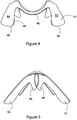
- the frame 12 will now be described in more detail with reference to Figures 2, 3 , 4 and 5 , perspective, top, side and then views of the support structure frame 12 of Figure 1 .
- the frame 12 comprises a single piece of resilient polymeric material and defines a head engaging portion 30 and a shoulder engaging portion 40. As will be shown, the shoulder engaging portion 40 is adapted to spread the load of the user's head over a user's shoulder.
- the frame 12 is shaped to the contour of the user's body from the head engaging portion 30 the shoulder engaging portion 40.
- the head engaging portion 30 comprises a first head engaging limb 32 and a second head engaging limb 34, the first and second head engaging limbs 32, 34, being connected by a head engaging portion connecting member 36.
- the shoulder engaging portion 40 comprises a first shoulder engaging limb 42 and a second shoulder engaging limb 44, the first and second shoulder engaging limbs 42, 44 being connected by a shoulder engaging portion connecting member 46.
- the head engaging portion limbs 32, 34 have respective head engaging surfaces 52, 54 which are angled towards each other to cup, in use, a part of user's jaw.
- the shoulder engaging portion limbs 42, 44 have respective shoulder engaging surfaces 62, 64 which also angled towards each other to cup between them two portions of the convex surface of a user's shoulder when in use.
- the limbs 32, 34, 42, 44 are paddle shaped in that they are wider at their free ends, 56, 58, 66, 68 than at their connecting ends 57, 59, 67, 69 where they join their respective connecting members 36, 46
- the frame 12 is in an uncompressed configuration. That is, the configuration shown on these Figures is a "not in use” configuration, the frame 12 being adapted to be compressed under the weight of the user's head. In this uncompressed configuration, the head engaging portion connecting member 36 and the shoulder engaging portion connecting member 46 are in contact at their respective midpoint's 38, 48. This will be discussed further in due course
- the frame 12 is fitted into the pocket 18 of the scarf 16.
- the sides of the pocket 80, 82 maintain a substantially constant spacing between the head engaging portion limbs 32, 34 and a substantially constant spacing between the shoulder engaging portion limbs 42, 44.
- the scarf surface 84 providing a bridging means 86 to provide a comfortable contact surface for the user.
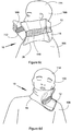
- the user 100 places the first end of the scarf 20 containing the frame 12 inside the scarf pocket 18 against their neck 102 such that the frame head engaging portion 30 rests against the underside of the user's jaw 104 and the frame shoulder engaging portion 40 lies across the user's shoulder 106.
- the user 100 takes a scarf second end 108 and passes it around their neck 102, until the scarf encircles their neck 102.
- the scarf first and second ends 20,108 are provided with hook and loop fastener portions 110, 112 which are brought together to secure the support structure to the user 100, thereby providing structure 10 adapted to at least partially support the user's head 114 permitting them to sleep comfortably in an upright position.
- FIG. 7 a close-up of the frame 10 shown in Figure 6B in which the frame 12 is partially compressed, it will be noted that the head engaging portion connecting member 36 and a shoulder engaging portion connecting member 46 for much of the length of the respective portions.
- This provides extra rigidity to the support structure 10, allowing for an initial "give” when the user 100 puts the weight of their head 114 on the support structure 10 by providing more resistance as the user applied weight increases and the size of the contact area between the connecting members 36, 46 increases.
- the bridging means may include an elasticated strap between the free ends of the limbs.
Landscapes
- Engineering & Computer Science (AREA)
- Aviation & Aerospace Engineering (AREA)
- Transportation (AREA)
- Mechanical Engineering (AREA)
- Health & Medical Sciences (AREA)
- General Health & Medical Sciences (AREA)
- Otolaryngology (AREA)
- Pulmonology (AREA)
- Orthopedics, Nursing, And Contraception (AREA)
- Helmets And Other Head Coverings (AREA)
- Carriages For Children, Sleds, And Other Hand-Operated Vehicles (AREA)
- Prostheses (AREA)
Claims (14)
- Stützstruktur (10) zum zumindest teilweisen Stützen des Kopfes eines Benutzers, wobei die Stützstruktur (10) umfasst:einen Rahmen (12) mit einen kopfumschließenden Abschnitt (30) und einen schulterumschließenden Abschnitt (40),wobei der Rahmen adaptiert ist, um unter dem Gewicht des Kopfes des Benutzers komprimiert zu werden;wobei der Rahmen (12) auf die Kontur des Körpers des Benutzers zwischen dem kopfumschließenden Abschnitt (30) und dem schulterumschließenden Abschnitt (40) geformt ist, sodass in Verwendung der schulterumschließende Abschnitt in der Lage ist, die Belastung durch den Kopf des Benutzers auf die Schulter eines Benutzers zu verteilen,dadurch gekennzeichnet, dass die Stützstruktur (10) ein Ankermittel (14) umfasst, welches adaptiert ist, um den Rahmen (12) in Verwendung am Nacken eines Benutzers zu sichern und um den Rahmen (12) gegen den Nacken des Benutzers zu drücken,wobei das Ankermittel (14) eine gestreckte Länge von Textilmaterial umfasst, und wobei die gestreckte Länge von Textilmaterial ein Schal (16) ist.
- Stützstruktur nach Anspruch 1, wobei der Rahmen (12) eine erste Oberfläche und eine zweite Oberfläche hat, wobei die erste Oberfläche in Wesentlichen konvex ist und die zweite Oberfläche im Wesentlichen konkav ist.
- Stützstruktur nach Anspruch 2, wobei der kopfumschließende Abschnitt (30) und der schulterumschließende Abschnitt (40) die erste Oberfläche definieren.
- Stützstruktur nach einem der vorstehenden Ansprüche, wobei der Rahmen ein elastisches, flexibles Blech ist.
- Stützstruktur nach einem der vorstehenden Ansprüche, wobei der die Schulter umschließende Abschnitt (40) einen ersten schulterumschließenden Abschnittsschenkel (42) und einen zweiten schulterumschließenden Abschnittsschenkel (44) umfasst, welche durch ein Verbindungselement für schulterumschließende Abschnitte (46) verbunden sind; und wobei der kopfumschließende Abschnitt einen ersten Schenkel (32) und einen zweiten Schenkel (34) umfasst, welche durch ein Verbindungselement für kopfumschließende Abschnitte (36) verbunden sind; wobei der erste und zweite schulterumschließende Abschnittsschenkel (42, 44) sich von dem kopfumschließenden Abschnitt (30) erstrecken.
- Stützstruktur nach Anspruch 5, wobei der erste schulterumschließende Abschnittsschenkel (42) und der zweite schulterumschließende Abschnittsschenkel (44) adaptiert sind, um die Schulter eines Benutzers zu überspannen.
- Stützstruktur nach Anspruch 5 oder Anspruch 6, wobei die Stützstruktur weiter ein Überbrückungsmittel für kopfumschließende Abschnitte (86) umfasst, welches den ersten kopfumschließenden Abschnittsschenkel (32) mit dem zweiten kopfumschließenden Abschnittsschenkel (34) verbindet, ein Überbrückungsmittel für schulterumschließende Abschnitte (86) ein Ende des ersten schulterumschließenden Abschnittsschenkels (42) mit einem Ende des zweiten schulterumschließenden Abschnittsschenkels (46) verbindet, die ersten und zweiten Enden der schulterumschließenden Abschnittsschenkel fern von dem kopfumschließenden Abschnitt (40) sind, wobei das Überbrückungsmittel für schulterumschließende Abschnitte (86) sich in Verwendung über die Schulter erstreckt, um das Gewicht des Kopfes des Benutzers über einen größeren Bereich zu verteilen.
- Stützstruktur nach einem der vorstehenden Ansprüche, wobei das Ankermittel (14) einen rahmenaufnehmenden Abschnitt definiert und der rahmenaufnehmende Abschnitt eine Tasche (18) ist.
- Stützstruktur nach Anspruch 8, wobei der rahmenaufnehmende Abschnitt sich an einem ersten Ende des Ankermittels befindet.
- Stützstruktur nach einem der Ansprüche 7 bis 9, wenn abhängig von Anspruch 7, wobei das Überbrückungsmittel für kopfumschließende Abschnitte und das Überbrückungsmittel für schulterumschließende Abschnitte durch das Ankermittel oder durch den rahmenaufnehmenden Abschnitt definiert sind.
- Stützstruktur nach einem der Ansprüche 7 bis 10, wobei das Überbrückungsmittel ein Netz ist.
- Stützstruktur nach einem der Ansprüche 5 bis 11, wobei das Verbindungselement für kopfumschließende Abschnitte und das Verbindungselement für schulterumschließende Abschnitte ineinander eingreifen, wenn der Rahmen komprimiert wird, und einer weiteren Kompression des Rahmens widerstehen.
- Stützstruktur nach einem der Ansprüche 5 bis 12, wobei die kopfumschließenden Abschnittsschenkel (32, 34) entsprechende kopfumschließende Oberflächen (52, 54) aufweisen, welche zueinander abgewinkelt sind, um in Verwendung einen Teil des Kiefers eines Benutzers zu umschließen.
- Stützstruktur nach einem der Ansprüche 5 bis 13, wobei die schulterumschließenden Abschnittsschenkel (42, 44) entsprechende schulterumschließende Oberflächen (62, 64) aufweisen, welche zueinander abgewinkelt sind, um in Verwendung zwischen ihnen zwei Abschnitte einer konvexen Oberfläche der Schulter eines Benutzers zu umschließen.
Applications Claiming Priority (4)
| Application Number | Priority Date | Filing Date | Title |
|---|---|---|---|
| GBGB1209898.4A GB201209898D0 (en) | 2012-06-02 | 2012-06-02 | Improved travel support structure |
| GBGB1211489.8A GB201211489D0 (en) | 2012-06-28 | 2012-06-28 | Improved travel support structure |
| GB201307905A GB201307905D0 (en) | 2013-05-01 | 2013-05-01 | Improved Travel Support Structure |
| PCT/GB2013/000246 WO2013178979A1 (en) | 2012-06-02 | 2013-05-30 | Improved travel support structure |
Publications (2)
| Publication Number | Publication Date |
|---|---|
| EP2854601A1 EP2854601A1 (de) | 2015-04-08 |
| EP2854601B1 true EP2854601B1 (de) | 2020-11-25 |
Family
ID=48790485
Family Applications (1)
| Application Number | Title | Priority Date | Filing Date |
|---|---|---|---|
| EP13736935.1A Active EP2854601B1 (de) | 2012-06-02 | 2013-05-30 | Verbesserte reisestützstruktur |
Country Status (10)
| Country | Link |
|---|---|
| US (5) | US10617215B2 (de) |
| EP (1) | EP2854601B1 (de) |
| JP (1) | JP6534614B2 (de) |
| CN (2) | CN111265046B (de) |
| AU (1) | AU2013269365C1 (de) |
| CA (1) | CA2914121C (de) |
| ES (1) | ES2862674T3 (de) |
| GB (2) | GB2517868A (de) |
| SG (2) | SG10201610070QA (de) |
| WO (1) | WO2013178979A1 (de) |
Families Citing this family (37)
| Publication number | Priority date | Publication date | Assignee | Title |
|---|---|---|---|---|
| US8141187B2 (en) | 2010-03-22 | 2012-03-27 | Alice Jean Schwingendorf | Sleepy head's/neck pillow invention |
| US9021636B2 (en) * | 2010-03-22 | 2015-05-05 | Alice Jean Schwingendorf | Sleepy heads neck pillow |
| CA2830918C (en) | 2011-03-31 | 2022-07-26 | Felmont Farrell Eaves, Iii | Force modulating tissue bridge |
| GB201307905D0 (en) * | 2013-05-01 | 2013-06-12 | Coolside Ltd | Improved Travel Support Structure |
| CN111265046B (zh) | 2012-06-02 | 2022-06-17 | 酷赛德有限公司 | 改进的旅行支承结构 |
| USD858782S1 (en) * | 2012-06-02 | 2019-09-03 | Coolside Limited | Head and neck support frame of a travel support structure |
| US9943180B2 (en) * | 2013-03-07 | 2018-04-17 | Obedo Enterprises, Inc. | Travel pillow and method for storing |
| USD754454S1 (en) | 2014-06-04 | 2016-04-26 | Alice Jean Schwingendorf | Pillow |
| CN104816654B (zh) * | 2015-05-26 | 2017-09-19 | 郝雨 | 一种固定式护颈托枕 |
| US20170071270A1 (en) * | 2015-09-10 | 2017-03-16 | Carol Ann Morse | Versatile Scarf Garment |
| CN108601465A (zh) * | 2015-09-29 | 2018-09-28 | 卡布公司 | 具有下巴支撑件、多个锚接点以及磁性夹的颈枕 |
| AU2017345707B2 (en) | 2016-10-21 | 2023-05-18 | Brijjit Medical, Inc. | Force modulating tissue bridges, associated tools, kits and methods |
| USD830562S1 (en) * | 2016-12-20 | 2018-10-09 | Aladdin Co., Ltd | Posture correction device |
| USD844155S1 (en) | 2017-06-06 | 2019-03-26 | Coolside Limited | Head supporting travel accessory |
| USD844154S1 (en) | 2017-06-06 | 2019-03-26 | Coolside Limited | Head supporting travel accessory |
| USD858779S1 (en) * | 2017-10-02 | 2019-09-03 | Eileen Durfee | Neck roll spinal brace support |
| USD859668S1 (en) * | 2017-10-02 | 2019-09-10 | Eileen Durfee | Back roll spinal brace support |
| USD876641S1 (en) | 2017-10-20 | 2020-02-25 | Emrge, Llc. | Medical article for treating a wound and/or scar tissue |
| GB201805175D0 (en) * | 2018-03-29 | 2018-05-16 | Coolside Ltd | Anchored head suppporting travel accessory |
| USD876654S1 (en) * | 2018-04-24 | 2020-02-25 | Ossur Iceland Ehf | Posterior strut |
| US20200000236A1 (en) * | 2018-06-27 | 2020-01-02 | Frank Wu | Neck Support Article |
| CN109223276A (zh) * | 2018-08-01 | 2019-01-18 | 苏州大学 | 多自由度颈椎升降牵引器 |
| USD947574S1 (en) * | 2018-08-20 | 2022-04-05 | Coolside Limited | Internal assembly for travel accessory |
| USD957846S1 (en) * | 2018-08-20 | 2022-07-19 | Coolside Limited | Travel accessory |
| USD862713S1 (en) | 2019-04-05 | 2019-10-08 | Allan Wendling | Frame for a head and neck support |
| USD944982S1 (en) * | 2019-05-17 | 2022-03-01 | Bonemodels S.L.U. | Dental retractor |
| EP3741260B1 (de) * | 2019-05-23 | 2023-06-21 | Jensen, Gemma | Kissen |
| USD919821S1 (en) * | 2019-06-05 | 2021-05-18 | 3M Innovative Properties Company | Brace strap |
| USD1023320S1 (en) * | 2019-06-13 | 2024-04-16 | Peyton Ventures, LLC | Device for the treatment of a bruise |
| US12458355B2 (en) | 2019-10-11 | 2025-11-04 | Brij Medical, Inc. | Medical device for applying force on biological tissue, or the like |
| USD878611S1 (en) | 2019-11-06 | 2020-03-17 | Xiaofeng Zhuang | Support frame of a neck cover |
| CN110638244B (zh) * | 2019-11-06 | 2024-05-17 | 广州铧世家具制造有限公司 | 一种头枕 |
| USD939094S1 (en) * | 2020-03-18 | 2021-12-21 | Ottobock Se & Co. Kgaa | Orthosis |
| US10893754B1 (en) | 2020-04-09 | 2021-01-19 | Jay Patrick Cooke | Modular and adjustable headrest |
| USD980434S1 (en) | 2021-01-14 | 2023-03-07 | Emrge, Llc | Medical article for treating a wound and/or scar tissue |
| USD1063081S1 (en) * | 2022-04-18 | 2025-02-18 | Averto Medical, Inc. | Medical dressing |
| USD993671S1 (en) | 2023-03-07 | 2023-08-01 | William L. Taylor, Jr. | Travel pillow |
Citations (2)
| Publication number | Priority date | Publication date | Assignee | Title |
|---|---|---|---|---|
| US6447468B1 (en) * | 2001-08-08 | 2002-09-10 | James T. Hankins | Portable cervical traction apparatus |
| WO2014181128A1 (en) * | 2013-05-09 | 2014-11-13 | The University Of Sheffield | Neck orthosis |
Family Cites Families (49)
| Publication number | Priority date | Publication date | Assignee | Title |
|---|---|---|---|---|
| US2818063A (en) * | 1954-01-13 | 1957-12-31 | W E Isle Company | Cervical collar |
| US3776224A (en) | 1972-02-24 | 1973-12-04 | Medical Dev Corp | Dynamic cervical support |
| US4034747A (en) * | 1976-04-02 | 1977-07-12 | New Research And Development Lab., Inc. | Cervical collar |
| IT1118704B (it) * | 1979-05-28 | 1986-03-03 | Pavetto Gian Carlo | Protesi particolarmente per artrosi cervicale |
| US4520801A (en) * | 1983-07-08 | 1985-06-04 | Max Lerman | Cervical collar |
| US4854306A (en) * | 1983-12-19 | 1989-08-08 | Pujals Jr Charles | Cervical/occipital support |
| US4757554A (en) * | 1986-07-07 | 1988-07-19 | Blair George A | Skiers safety harness |
| US4782824A (en) * | 1987-07-23 | 1988-11-08 | Davies Gerald G | External airway support |
| US5205813A (en) * | 1990-01-08 | 1993-04-27 | Schmidt Shawn M | Cephalic and cervical support appliance |
| US5220700A (en) * | 1992-07-08 | 1993-06-22 | Liu Ing Nan | Protective pillow |
| US5505523A (en) * | 1995-02-14 | 1996-04-09 | Wang; Ful-Lang | Safety nap cushion for use with a chair back |
| JPH0956737A (ja) * | 1995-08-18 | 1997-03-04 | Tetsuo Takada | 頚部補助カラー |
| US5722939A (en) | 1996-07-25 | 1998-03-03 | Linda Hohlen | Body support liner for a neck brace |
| US6289538B1 (en) * | 1999-12-16 | 2001-09-18 | Binkley W. Fidge | Variable contour head support |
| GB0020573D0 (en) | 2000-08-22 | 2000-10-11 | Flanerty John F | The personal head rest |
| US6679557B2 (en) * | 2002-01-23 | 2004-01-20 | Pent Products, Inc. | Article of furniture having a support member with an adjustable contour |
| US7128724B2 (en) | 2003-04-14 | 2006-10-31 | Ohana Medical Concepts, Llc | Cervical spine brace and traction device |
| CA2542432A1 (en) * | 2003-10-17 | 2005-05-06 | Biocybernetics International | Cervical support system |
| US7197781B2 (en) * | 2003-11-05 | 2007-04-03 | Ramsbottom John E | Neck support |
| EP1700544A1 (de) * | 2005-03-11 | 2006-09-13 | LaSch ApS | Stütze für den Hals und den Kopf einer Person |
| CN2818218Y (zh) * | 2005-09-15 | 2006-09-20 | 孙伟 | 汽车座椅头部固定装置 |
| USD541096S1 (en) | 2005-09-20 | 2007-04-24 | Daniela Georgescu | Pillow |
| CN2877445Y (zh) * | 2006-04-06 | 2007-03-14 | 长春工业大学 | 旅途睡眠头托 |
| JP4061336B1 (ja) * | 2006-12-26 | 2008-03-19 | 株式会社ワコール | 運動用衣類 |
| CN201015494Y (zh) * | 2007-03-01 | 2008-02-06 | 胡啸鸣 | 一种座椅头枕 |
| USD616997S1 (en) * | 2009-09-14 | 2010-06-01 | Ossur Hf | Orthopedic device |
| US8418293B2 (en) * | 2009-10-22 | 2013-04-16 | Edward Tansingco | Travel pillow providing head and neck alignment during use |
| CN201550936U (zh) * | 2009-12-10 | 2010-08-18 | 皮武 | 充气折叠式座椅枕靠 |
| US20110169316A1 (en) * | 2010-01-11 | 2011-07-14 | Marques Paul Goei | Portable Travel Headrest |
| US8141187B2 (en) * | 2010-03-22 | 2012-03-27 | Alice Jean Schwingendorf | Sleepy head's/neck pillow invention |
| US9021636B2 (en) * | 2010-03-22 | 2015-05-05 | Alice Jean Schwingendorf | Sleepy heads neck pillow |
| KR200450197Y1 (ko) * | 2010-04-01 | 2010-09-09 | 김원배 | 머리카락 삽입홈이 구비된 목 베개 |
| USD690015S1 (en) * | 2010-07-16 | 2013-09-17 | Mamma Guard Pty Ltd. | Truncal orthosis |
| US8898840B1 (en) * | 2011-10-28 | 2014-12-02 | Michael S. Majette | Head and neck support device |
| CN111265046B (zh) * | 2012-06-02 | 2022-06-17 | 酷赛德有限公司 | 改进的旅行支承结构 |
| USD739668S1 (en) * | 2014-03-04 | 2015-09-29 | Byron Owens | Travel pillow |
| US9968197B2 (en) * | 2014-03-11 | 2018-05-15 | Cabeau, Inc. | Travel pillow |
| US10321765B2 (en) * | 2014-03-11 | 2019-06-18 | Cabeau, Inc. | Travel pillow |
| USD773674S1 (en) * | 2014-10-02 | 2016-12-06 | Elekta Ab Publ | Frame for neurological fixation device |
| USD762400S1 (en) * | 2014-10-20 | 2016-08-02 | Cabeau, Inc. | Travel pillow |
| US10188311B2 (en) | 2015-12-04 | 2019-01-29 | Chiming Huang | Device to reduce traumatic brain injury |
| KR101616119B1 (ko) | 2015-02-04 | 2016-04-28 | 김현성 | 로도시스를 형성하는 경추 보조기 |
| USD775862S1 (en) * | 2015-07-20 | 2017-01-10 | Shen Zhen Lian Da Sponge Product Co., Ltd | Cushion |
| USD778086S1 (en) * | 2015-08-21 | 2017-02-07 | Gas Brand Starter, Llc | Travel pillow |
| US20180049568A1 (en) * | 2016-02-12 | 2018-02-22 | Aaron Cruz | Portable full head support pillow convertible cushion |
| GB201805175D0 (en) | 2018-03-29 | 2018-05-16 | Coolside Ltd | Anchored head suppporting travel accessory |
| USD957846S1 (en) * | 2018-08-20 | 2022-07-19 | Coolside Limited | Travel accessory |
| USD862713S1 (en) * | 2019-04-05 | 2019-10-08 | Allan Wendling | Frame for a head and neck support |
| USD878611S1 (en) * | 2019-11-06 | 2020-03-17 | Xiaofeng Zhuang | Support frame of a neck cover |
-
2013
- 2013-05-30 CN CN202010080502.5A patent/CN111265046B/zh active Active
- 2013-05-30 AU AU2013269365A patent/AU2013269365C1/en active Active
- 2013-05-30 CA CA2914121A patent/CA2914121C/en active Active
- 2013-05-30 CN CN201380029142.4A patent/CN104427912B/zh active Active
- 2013-05-30 US US14/405,115 patent/US10617215B2/en active Active
- 2013-05-30 GB GB1422492.7A patent/GB2517868A/en not_active Withdrawn
- 2013-05-30 WO PCT/GB2013/000246 patent/WO2013178979A1/en not_active Ceased
- 2013-05-30 ES ES13736935T patent/ES2862674T3/es active Active
- 2013-05-30 SG SG10201610070QA patent/SG10201610070QA/en unknown
- 2013-05-30 EP EP13736935.1A patent/EP2854601B1/de active Active
- 2013-05-30 SG SG11201509893QA patent/SG11201509893QA/en unknown
- 2013-05-30 JP JP2015514571A patent/JP6534614B2/ja active Active
- 2013-06-03 GB GB1309817.3A patent/GB2504592B/en active Active
-
2017
- 2017-11-03 US US29/624,837 patent/USD815747S1/en active Active
- 2017-12-15 US US15/843,890 patent/US10098464B2/en active Active
-
2020
- 2020-02-12 US US16/789,159 patent/US12150557B2/en active Active
-
2024
- 2024-07-23 US US18/780,631 patent/US20240374036A1/en active Pending
Patent Citations (2)
| Publication number | Priority date | Publication date | Assignee | Title |
|---|---|---|---|---|
| US6447468B1 (en) * | 2001-08-08 | 2002-09-10 | James T. Hankins | Portable cervical traction apparatus |
| WO2014181128A1 (en) * | 2013-05-09 | 2014-11-13 | The University Of Sheffield | Neck orthosis |
Also Published As
| Publication number | Publication date |
|---|---|
| ES2862674T3 (es) | 2021-10-07 |
| AU2013269365A1 (en) | 2015-01-22 |
| US12150557B2 (en) | 2024-11-26 |
| JP2015518750A (ja) | 2015-07-06 |
| GB2517868A (en) | 2015-03-04 |
| CN111265046B (zh) | 2022-06-17 |
| AU2013269365C1 (en) | 2024-06-20 |
| CA2914121A1 (en) | 2013-12-05 |
| CN104427912A (zh) | 2015-03-18 |
| US10617215B2 (en) | 2020-04-14 |
| US20200178691A1 (en) | 2020-06-11 |
| US10098464B2 (en) | 2018-10-16 |
| SG11201509893QA (en) | 2016-01-28 |
| GB201309817D0 (en) | 2013-07-17 |
| CA2914121C (en) | 2021-03-30 |
| WO2013178979A1 (en) | 2013-12-05 |
| HK1209003A1 (en) | 2016-03-24 |
| AU2013269365B2 (en) | 2017-05-25 |
| US20150157130A1 (en) | 2015-06-11 |
| GB2504592B (en) | 2018-03-21 |
| CN111265046A (zh) | 2020-06-12 |
| CN104427912B (zh) | 2020-02-28 |
| GB2504592A (en) | 2014-02-05 |
| USD815747S1 (en) | 2018-04-17 |
| EP2854601A1 (de) | 2015-04-08 |
| US20180103764A1 (en) | 2018-04-19 |
| SG10201610070QA (en) | 2017-01-27 |
| JP6534614B2 (ja) | 2019-06-26 |
| US20240374036A1 (en) | 2024-11-14 |
Similar Documents
| Publication | Publication Date | Title |
|---|---|---|
| EP2854601B1 (de) | Verbesserte reisestützstruktur | |
| CN104244772B (zh) | 对垫的改进及与垫相关的改进 | |
| CN101166446B (zh) | 用于支撑人体颈部和头部的支撑器 | |
| US9603458B2 (en) | Knee pillow | |
| US20150061340A1 (en) | Head Hammock | |
| US8156938B2 (en) | Head support | |
| HK1209003B (en) | Improved travel support structure | |
| JP3140457U (ja) | 枕 | |
| CN210644388U (zh) | 一种新生儿鸟巢 | |
| KR200466308Y1 (ko) | 기능성 미용베개 | |
| CN217137303U (zh) | 一种便携护颈侧卧枕 | |
| CN205251100U (zh) | 护颈元宝型枕头 | |
| US20090183749A1 (en) | Hairstyle keeper | |
| CN202507962U (zh) | 一种座椅头靠 | |
| CN205251092U (zh) | 一种可调高低的枕头 | |
| TWM447155U (zh) | 背靠墊結構改良 | |
| HK1204892B (zh) | 对垫的改进及与垫相关的改进 |
Legal Events
| Date | Code | Title | Description |
|---|---|---|---|
| PUAI | Public reference made under article 153(3) epc to a published international application that has entered the european phase |
Free format text: ORIGINAL CODE: 0009012 |
|
| 17P | Request for examination filed |
Effective date: 20141209 |
|
| AK | Designated contracting states |
Kind code of ref document: A1 Designated state(s): AL AT BE BG CH CY CZ DE DK EE ES FI FR GB GR HR HU IE IS IT LI LT LU LV MC MK MT NL NO PL PT RO RS SE SI SK SM TR |
|
| AX | Request for extension of the european patent |
Extension state: BA ME |
|
| DAX | Request for extension of the european patent (deleted) | ||
| REG | Reference to a national code |
Ref country code: HK Ref legal event code: DE Ref document number: 1209003 Country of ref document: HK |
|
| 17Q | First examination report despatched |
Effective date: 20160812 |
|
| STAA | Information on the status of an ep patent application or granted ep patent |
Free format text: STATUS: EXAMINATION IS IN PROGRESS |
|
| GRAP | Despatch of communication of intention to grant a patent |
Free format text: ORIGINAL CODE: EPIDOSNIGR1 |
|
| STAA | Information on the status of an ep patent application or granted ep patent |
Free format text: STATUS: GRANT OF PATENT IS INTENDED |
|
| RIC1 | Information provided on ipc code assigned before grant |
Ipc: A47C 7/38 20060101AFI20200512BHEP |
|
| INTG | Intention to grant announced |
Effective date: 20200609 |
|
| GRAS | Grant fee paid |
Free format text: ORIGINAL CODE: EPIDOSNIGR3 |
|
| GRAA | (expected) grant |
Free format text: ORIGINAL CODE: 0009210 |
|
| STAA | Information on the status of an ep patent application or granted ep patent |
Free format text: STATUS: THE PATENT HAS BEEN GRANTED |
|
| AK | Designated contracting states |
Kind code of ref document: B1 Designated state(s): AL AT BE BG CH CY CZ DE DK EE ES FI FR GB GR HR HU IE IS IT LI LT LU LV MC MK MT NL NO PL PT RO RS SE SI SK SM TR |
|
| RAP1 | Party data changed (applicant data changed or rights of an application transferred) |
Owner name: COOLSIDE LIMITED |
|
| REG | Reference to a national code |
Ref country code: GB Ref legal event code: FG4D |
|
| RIN1 | Information on inventor provided before grant (corrected) |
Inventor name: CORRIGAN, MICHAEL Inventor name: KELLOCK, DAVID |
|
| REG | Reference to a national code |
Ref country code: CH Ref legal event code: EP |
|
| REG | Reference to a national code |
Ref country code: DE Ref legal event code: R096 Ref document number: 602013074292 Country of ref document: DE |
|
| REG | Reference to a national code |
Ref country code: AT Ref legal event code: REF Ref document number: 1337285 Country of ref document: AT Kind code of ref document: T Effective date: 20201215 |
|
| REG | Reference to a national code |
Ref country code: IE Ref legal event code: FG4D |
|
| REG | Reference to a national code |
Ref country code: CH Ref legal event code: NV Representative=s name: VALIPAT S.A. C/O BOVARD SA NEUCHATEL, CH |
|
| REG | Reference to a national code |
Ref country code: SE Ref legal event code: TRGR |
|
| REG | Reference to a national code |
Ref country code: NL Ref legal event code: FP |
|
| PG25 | Lapsed in a contracting state [announced via postgrant information from national office to epo] |
Ref country code: PT Free format text: LAPSE BECAUSE OF FAILURE TO SUBMIT A TRANSLATION OF THE DESCRIPTION OR TO PAY THE FEE WITHIN THE PRESCRIBED TIME-LIMIT Effective date: 20210325 Ref country code: FI Free format text: LAPSE BECAUSE OF FAILURE TO SUBMIT A TRANSLATION OF THE DESCRIPTION OR TO PAY THE FEE WITHIN THE PRESCRIBED TIME-LIMIT Effective date: 20201125 Ref country code: RS Free format text: LAPSE BECAUSE OF FAILURE TO SUBMIT A TRANSLATION OF THE DESCRIPTION OR TO PAY THE FEE WITHIN THE PRESCRIBED TIME-LIMIT Effective date: 20201125 Ref country code: GR Free format text: LAPSE BECAUSE OF FAILURE TO SUBMIT A TRANSLATION OF THE DESCRIPTION OR TO PAY THE FEE WITHIN THE PRESCRIBED TIME-LIMIT Effective date: 20210226 |
|
| REG | Reference to a national code |
Ref country code: NO Ref legal event code: T2 Effective date: 20201125 |
|
| PG25 | Lapsed in a contracting state [announced via postgrant information from national office to epo] |
Ref country code: LV Free format text: LAPSE BECAUSE OF FAILURE TO SUBMIT A TRANSLATION OF THE DESCRIPTION OR TO PAY THE FEE WITHIN THE PRESCRIBED TIME-LIMIT Effective date: 20201125 Ref country code: IS Free format text: LAPSE BECAUSE OF FAILURE TO SUBMIT A TRANSLATION OF THE DESCRIPTION OR TO PAY THE FEE WITHIN THE PRESCRIBED TIME-LIMIT Effective date: 20210325 Ref country code: PL Free format text: LAPSE BECAUSE OF FAILURE TO SUBMIT A TRANSLATION OF THE DESCRIPTION OR TO PAY THE FEE WITHIN THE PRESCRIBED TIME-LIMIT Effective date: 20201125 Ref country code: BG Free format text: LAPSE BECAUSE OF FAILURE TO SUBMIT A TRANSLATION OF THE DESCRIPTION OR TO PAY THE FEE WITHIN THE PRESCRIBED TIME-LIMIT Effective date: 20210225 |
|
| REG | Reference to a national code |
Ref country code: LT Ref legal event code: MG9D |
|
| PG25 | Lapsed in a contracting state [announced via postgrant information from national office to epo] |
Ref country code: HR Free format text: LAPSE BECAUSE OF FAILURE TO SUBMIT A TRANSLATION OF THE DESCRIPTION OR TO PAY THE FEE WITHIN THE PRESCRIBED TIME-LIMIT Effective date: 20201125 |
|
| PG25 | Lapsed in a contracting state [announced via postgrant information from national office to epo] |
Ref country code: RO Free format text: LAPSE BECAUSE OF FAILURE TO SUBMIT A TRANSLATION OF THE DESCRIPTION OR TO PAY THE FEE WITHIN THE PRESCRIBED TIME-LIMIT Effective date: 20201125 Ref country code: SK Free format text: LAPSE BECAUSE OF FAILURE TO SUBMIT A TRANSLATION OF THE DESCRIPTION OR TO PAY THE FEE WITHIN THE PRESCRIBED TIME-LIMIT Effective date: 20201125 Ref country code: LT Free format text: LAPSE BECAUSE OF FAILURE TO SUBMIT A TRANSLATION OF THE DESCRIPTION OR TO PAY THE FEE WITHIN THE PRESCRIBED TIME-LIMIT Effective date: 20201125 Ref country code: CZ Free format text: LAPSE BECAUSE OF FAILURE TO SUBMIT A TRANSLATION OF THE DESCRIPTION OR TO PAY THE FEE WITHIN THE PRESCRIBED TIME-LIMIT Effective date: 20201125 Ref country code: EE Free format text: LAPSE BECAUSE OF FAILURE TO SUBMIT A TRANSLATION OF THE DESCRIPTION OR TO PAY THE FEE WITHIN THE PRESCRIBED TIME-LIMIT Effective date: 20201125 Ref country code: SM Free format text: LAPSE BECAUSE OF FAILURE TO SUBMIT A TRANSLATION OF THE DESCRIPTION OR TO PAY THE FEE WITHIN THE PRESCRIBED TIME-LIMIT Effective date: 20201125 |
|
| REG | Reference to a national code |
Ref country code: DE Ref legal event code: R097 Ref document number: 602013074292 Country of ref document: DE |
|
| PG25 | Lapsed in a contracting state [announced via postgrant information from national office to epo] |
Ref country code: DK Free format text: LAPSE BECAUSE OF FAILURE TO SUBMIT A TRANSLATION OF THE DESCRIPTION OR TO PAY THE FEE WITHIN THE PRESCRIBED TIME-LIMIT Effective date: 20201125 |
|
| PLBE | No opposition filed within time limit |
Free format text: ORIGINAL CODE: 0009261 |
|
| STAA | Information on the status of an ep patent application or granted ep patent |
Free format text: STATUS: NO OPPOSITION FILED WITHIN TIME LIMIT |
|
| REG | Reference to a national code |
Ref country code: ES Ref legal event code: FG2A Ref document number: 2862674 Country of ref document: ES Kind code of ref document: T3 Effective date: 20211007 |
|
| PG25 | Lapsed in a contracting state [announced via postgrant information from national office to epo] |
Ref country code: AL Free format text: LAPSE BECAUSE OF FAILURE TO SUBMIT A TRANSLATION OF THE DESCRIPTION OR TO PAY THE FEE WITHIN THE PRESCRIBED TIME-LIMIT Effective date: 20201125 |
|
| 26N | No opposition filed |
Effective date: 20210826 |
|
| PG25 | Lapsed in a contracting state [announced via postgrant information from national office to epo] |
Ref country code: SI Free format text: LAPSE BECAUSE OF FAILURE TO SUBMIT A TRANSLATION OF THE DESCRIPTION OR TO PAY THE FEE WITHIN THE PRESCRIBED TIME-LIMIT Effective date: 20201125 |
|
| PG25 | Lapsed in a contracting state [announced via postgrant information from national office to epo] |
Ref country code: MC Free format text: LAPSE BECAUSE OF FAILURE TO SUBMIT A TRANSLATION OF THE DESCRIPTION OR TO PAY THE FEE WITHIN THE PRESCRIBED TIME-LIMIT Effective date: 20201125 Ref country code: LU Free format text: LAPSE BECAUSE OF NON-PAYMENT OF DUE FEES Effective date: 20210530 |
|
| PG25 | Lapsed in a contracting state [announced via postgrant information from national office to epo] |
Ref country code: IS Free format text: LAPSE BECAUSE OF FAILURE TO SUBMIT A TRANSLATION OF THE DESCRIPTION OR TO PAY THE FEE WITHIN THE PRESCRIBED TIME-LIMIT Effective date: 20210325 |
|
| REG | Reference to a national code |
Ref country code: AT Ref legal event code: UEP Ref document number: 1337285 Country of ref document: AT Kind code of ref document: T Effective date: 20201125 |
|
| PG25 | Lapsed in a contracting state [announced via postgrant information from national office to epo] |
Ref country code: HU Free format text: LAPSE BECAUSE OF FAILURE TO SUBMIT A TRANSLATION OF THE DESCRIPTION OR TO PAY THE FEE WITHIN THE PRESCRIBED TIME-LIMIT; INVALID AB INITIO Effective date: 20130530 |
|
| PG25 | Lapsed in a contracting state [announced via postgrant information from national office to epo] |
Ref country code: CY Free format text: LAPSE BECAUSE OF FAILURE TO SUBMIT A TRANSLATION OF THE DESCRIPTION OR TO PAY THE FEE WITHIN THE PRESCRIBED TIME-LIMIT Effective date: 20201125 |
|
| P01 | Opt-out of the competence of the unified patent court (upc) registered |
Effective date: 20230529 |
|
| PG25 | Lapsed in a contracting state [announced via postgrant information from national office to epo] |
Ref country code: MK Free format text: LAPSE BECAUSE OF FAILURE TO SUBMIT A TRANSLATION OF THE DESCRIPTION OR TO PAY THE FEE WITHIN THE PRESCRIBED TIME-LIMIT Effective date: 20201125 |
|
| PG25 | Lapsed in a contracting state [announced via postgrant information from national office to epo] |
Ref country code: MT Free format text: LAPSE BECAUSE OF FAILURE TO SUBMIT A TRANSLATION OF THE DESCRIPTION OR TO PAY THE FEE WITHIN THE PRESCRIBED TIME-LIMIT Effective date: 20201125 |
|
| PGFP | Annual fee paid to national office [announced via postgrant information from national office to epo] |
Ref country code: NL Payment date: 20250526 Year of fee payment: 13 |
|
| PGFP | Annual fee paid to national office [announced via postgrant information from national office to epo] |
Ref country code: DE Payment date: 20250528 Year of fee payment: 13 |
|
| PGFP | Annual fee paid to national office [announced via postgrant information from national office to epo] |
Ref country code: GB Payment date: 20250409 Year of fee payment: 13 Ref country code: ES Payment date: 20250606 Year of fee payment: 13 |
|
| PGFP | Annual fee paid to national office [announced via postgrant information from national office to epo] |
Ref country code: NO Payment date: 20250521 Year of fee payment: 13 |
|
| PGFP | Annual fee paid to national office [announced via postgrant information from national office to epo] |
Ref country code: BE Payment date: 20250526 Year of fee payment: 13 Ref country code: IT Payment date: 20250522 Year of fee payment: 13 |
|
| PGFP | Annual fee paid to national office [announced via postgrant information from national office to epo] |
Ref country code: FR Payment date: 20250527 Year of fee payment: 13 |
|
| PGFP | Annual fee paid to national office [announced via postgrant information from national office to epo] |
Ref country code: CH Payment date: 20250601 Year of fee payment: 13 |
|
| PGFP | Annual fee paid to national office [announced via postgrant information from national office to epo] |
Ref country code: AT Payment date: 20250521 Year of fee payment: 13 |
|
| PGFP | Annual fee paid to national office [announced via postgrant information from national office to epo] |
Ref country code: TR Payment date: 20250509 Year of fee payment: 13 |
|
| PGFP | Annual fee paid to national office [announced via postgrant information from national office to epo] |
Ref country code: IE Payment date: 20250522 Year of fee payment: 13 |
|
| PGFP | Annual fee paid to national office [announced via postgrant information from national office to epo] |
Ref country code: SE Payment date: 20250526 Year of fee payment: 13 |