EP2854269A1 - Method for reducing the common mode current - Google Patents
Method for reducing the common mode current Download PDFInfo
- Publication number
- EP2854269A1 EP2854269A1 EP14306425.1A EP14306425A EP2854269A1 EP 2854269 A1 EP2854269 A1 EP 2854269A1 EP 14306425 A EP14306425 A EP 14306425A EP 2854269 A1 EP2854269 A1 EP 2854269A1
- Authority
- EP
- European Patent Office
- Prior art keywords
- current
- electrical
- circuit
- electronic component
- secondary winding
- Prior art date
- Legal status (The legal status is an assumption and is not a legal conclusion. Google has not performed a legal analysis and makes no representation as to the accuracy of the status listed.)
- Granted
Links
- 238000000034 method Methods 0.000 title claims abstract description 29
- 238000004804 winding Methods 0.000 claims abstract description 123
- 238000002347 injection Methods 0.000 claims abstract description 59
- 239000007924 injection Substances 0.000 claims abstract description 59
- 230000004907 flux Effects 0.000 claims abstract description 25
- 230000010355 oscillation Effects 0.000 claims abstract description 15
- 230000005415 magnetization Effects 0.000 claims abstract description 11
- 238000004146 energy storage Methods 0.000 claims abstract description 10
- 230000005347 demagnetization Effects 0.000 claims abstract description 9
- 238000005259 measurement Methods 0.000 claims description 35
- 230000008569 process Effects 0.000 abstract description 4
- 239000003990 capacitor Substances 0.000 description 33
- 230000007935 neutral effect Effects 0.000 description 15
- 238000011144 upstream manufacturing Methods 0.000 description 10
- 239000004020 conductor Substances 0.000 description 9
- 235000021183 entrée Nutrition 0.000 description 8
- 238000001914 filtration Methods 0.000 description 6
- 230000001174 ascending effect Effects 0.000 description 5
- 238000010586 diagram Methods 0.000 description 5
- 230000006698 induction Effects 0.000 description 5
- 239000000696 magnetic material Substances 0.000 description 5
- 238000001514 detection method Methods 0.000 description 4
- 238000012545 processing Methods 0.000 description 4
- 238000012546 transfer Methods 0.000 description 4
- 230000003071 parasitic effect Effects 0.000 description 3
- 230000009467 reduction Effects 0.000 description 3
- 239000000243 solution Substances 0.000 description 3
- 240000008042 Zea mays Species 0.000 description 2
- 230000007423 decrease Effects 0.000 description 2
- 238000002955 isolation Methods 0.000 description 2
- 239000000463 material Substances 0.000 description 2
- 244000045947 parasite Species 0.000 description 2
- 229920006395 saturated elastomer Polymers 0.000 description 2
- 230000009471 action Effects 0.000 description 1
- 238000005452 bending Methods 0.000 description 1
- 230000005540 biological transmission Effects 0.000 description 1
- 230000008859 change Effects 0.000 description 1
- 238000013461 design Methods 0.000 description 1
- 230000009977 dual effect Effects 0.000 description 1
- 230000000694 effects Effects 0.000 description 1
- 230000005611 electricity Effects 0.000 description 1
- 229940082150 encore Drugs 0.000 description 1
- 238000009434 installation Methods 0.000 description 1
- 230000010354 integration Effects 0.000 description 1
- 239000002184 metal Substances 0.000 description 1
- 238000013021 overheating Methods 0.000 description 1
- 230000035699 permeability Effects 0.000 description 1
- 230000004044 response Effects 0.000 description 1
- 230000000630 rising effect Effects 0.000 description 1
- 230000007704 transition Effects 0.000 description 1
- 229910000859 α-Fe Inorganic materials 0.000 description 1
Images


Classifications
-
- H—ELECTRICITY
- H02—GENERATION; CONVERSION OR DISTRIBUTION OF ELECTRIC POWER
- H02M—APPARATUS FOR CONVERSION BETWEEN AC AND AC, BETWEEN AC AND DC, OR BETWEEN DC AND DC, AND FOR USE WITH MAINS OR SIMILAR POWER SUPPLY SYSTEMS; CONVERSION OF DC OR AC INPUT POWER INTO SURGE OUTPUT POWER; CONTROL OR REGULATION THEREOF
- H02M1/00—Details of apparatus for conversion
- H02M1/12—Arrangements for reducing harmonics from ac input or output
-
- B—PERFORMING OPERATIONS; TRANSPORTING
- B60—VEHICLES IN GENERAL
- B60L—PROPULSION OF ELECTRICALLY-PROPELLED VEHICLES; SUPPLYING ELECTRIC POWER FOR AUXILIARY EQUIPMENT OF ELECTRICALLY-PROPELLED VEHICLES; ELECTRODYNAMIC BRAKE SYSTEMS FOR VEHICLES IN GENERAL; MAGNETIC SUSPENSION OR LEVITATION FOR VEHICLES; MONITORING OPERATING VARIABLES OF ELECTRICALLY-PROPELLED VEHICLES; ELECTRIC SAFETY DEVICES FOR ELECTRICALLY-PROPELLED VEHICLES
- B60L50/00—Electric propulsion with power supplied within the vehicle
- B60L50/50—Electric propulsion with power supplied within the vehicle using propulsion power supplied by batteries or fuel cells
- B60L50/51—Electric propulsion with power supplied within the vehicle using propulsion power supplied by batteries or fuel cells characterised by AC-motors
-
- H—ELECTRICITY
- H02—GENERATION; CONVERSION OR DISTRIBUTION OF ELECTRIC POWER
- H02M—APPARATUS FOR CONVERSION BETWEEN AC AND AC, BETWEEN AC AND DC, OR BETWEEN DC AND DC, AND FOR USE WITH MAINS OR SIMILAR POWER SUPPLY SYSTEMS; CONVERSION OF DC OR AC INPUT POWER INTO SURGE OUTPUT POWER; CONTROL OR REGULATION THEREOF
- H02M1/00—Details of apparatus for conversion
- H02M1/44—Circuits or arrangements for compensating for electromagnetic interference in converters or inverters
-
- B—PERFORMING OPERATIONS; TRANSPORTING
- B60—VEHICLES IN GENERAL
- B60L—PROPULSION OF ELECTRICALLY-PROPELLED VEHICLES; SUPPLYING ELECTRIC POWER FOR AUXILIARY EQUIPMENT OF ELECTRICALLY-PROPELLED VEHICLES; ELECTRODYNAMIC BRAKE SYSTEMS FOR VEHICLES IN GENERAL; MAGNETIC SUSPENSION OR LEVITATION FOR VEHICLES; MONITORING OPERATING VARIABLES OF ELECTRICALLY-PROPELLED VEHICLES; ELECTRIC SAFETY DEVICES FOR ELECTRICALLY-PROPELLED VEHICLES
- B60L2220/00—Electrical machine types; Structures or applications thereof
- B60L2220/50—Structural details of electrical machines
- B60L2220/54—Windings for different functions
-
- B—PERFORMING OPERATIONS; TRANSPORTING
- B60—VEHICLES IN GENERAL
- B60L—PROPULSION OF ELECTRICALLY-PROPELLED VEHICLES; SUPPLYING ELECTRIC POWER FOR AUXILIARY EQUIPMENT OF ELECTRICALLY-PROPELLED VEHICLES; ELECTRODYNAMIC BRAKE SYSTEMS FOR VEHICLES IN GENERAL; MAGNETIC SUSPENSION OR LEVITATION FOR VEHICLES; MONITORING OPERATING VARIABLES OF ELECTRICALLY-PROPELLED VEHICLES; ELECTRIC SAFETY DEVICES FOR ELECTRICALLY-PROPELLED VEHICLES
- B60L2240/00—Control parameters of input or output; Target parameters
- B60L2240/40—Drive Train control parameters
- B60L2240/42—Drive Train control parameters related to electric machines
- B60L2240/429—Current
-
- H—ELECTRICITY
- H02—GENERATION; CONVERSION OR DISTRIBUTION OF ELECTRIC POWER
- H02J—CIRCUIT ARRANGEMENTS OR SYSTEMS FOR SUPPLYING OR DISTRIBUTING ELECTRIC POWER; SYSTEMS FOR STORING ELECTRIC ENERGY
- H02J7/00—Circuit arrangements for charging or depolarising batteries or for supplying loads from batteries
- H02J7/0029—Circuit arrangements for charging or depolarising batteries or for supplying loads from batteries with safety or protection devices or circuits
-
- H—ELECTRICITY
- H02—GENERATION; CONVERSION OR DISTRIBUTION OF ELECTRIC POWER
- H02M—APPARATUS FOR CONVERSION BETWEEN AC AND AC, BETWEEN AC AND DC, OR BETWEEN DC AND DC, AND FOR USE WITH MAINS OR SIMILAR POWER SUPPLY SYSTEMS; CONVERSION OF DC OR AC INPUT POWER INTO SURGE OUTPUT POWER; CONTROL OR REGULATION THEREOF
- H02M1/00—Details of apparatus for conversion
- H02M1/12—Arrangements for reducing harmonics from ac input or output
- H02M1/123—Suppression of common mode voltage or current
-
- Y—GENERAL TAGGING OF NEW TECHNOLOGICAL DEVELOPMENTS; GENERAL TAGGING OF CROSS-SECTIONAL TECHNOLOGIES SPANNING OVER SEVERAL SECTIONS OF THE IPC; TECHNICAL SUBJECTS COVERED BY FORMER USPC CROSS-REFERENCE ART COLLECTIONS [XRACs] AND DIGESTS
- Y02—TECHNOLOGIES OR APPLICATIONS FOR MITIGATION OR ADAPTATION AGAINST CLIMATE CHANGE
- Y02T—CLIMATE CHANGE MITIGATION TECHNOLOGIES RELATED TO TRANSPORTATION
- Y02T10/00—Road transport of goods or passengers
- Y02T10/60—Other road transportation technologies with climate change mitigation effect
- Y02T10/64—Electric machine technologies in electromobility
-
- Y—GENERAL TAGGING OF NEW TECHNOLOGICAL DEVELOPMENTS; GENERAL TAGGING OF CROSS-SECTIONAL TECHNOLOGIES SPANNING OVER SEVERAL SECTIONS OF THE IPC; TECHNICAL SUBJECTS COVERED BY FORMER USPC CROSS-REFERENCE ART COLLECTIONS [XRACs] AND DIGESTS
- Y02—TECHNOLOGIES OR APPLICATIONS FOR MITIGATION OR ADAPTATION AGAINST CLIMATE CHANGE
- Y02T—CLIMATE CHANGE MITIGATION TECHNOLOGIES RELATED TO TRANSPORTATION
- Y02T10/00—Road transport of goods or passengers
- Y02T10/60—Other road transportation technologies with climate change mitigation effect
- Y02T10/70—Energy storage systems for electromobility, e.g. batteries
Definitions
- the object of the present invention is to reduce the common-mode current flowing between the internal mass of an electric circuit and the earth, when electrical energy is exchanged between a source of electrical energy external to said circuit and a storage unit. of electrical energy of said circuit.
- the source of electrical energy belongs for example to an electrical network including, but not limited to, an electrical network in which the neutral is connected directly to the earth.
- the electrical network may be an alternating voltage network, polyphase or not, and this voltage is then rectified to supply the electrical energy storage unit of the electrical circuit, for example a battery.
- the electrical circuit is for example embedded in a vehicle and may include an electric motor for the electric propulsion of the vehicle.
- the vehicle still includes a chassis.
- the chassis When the power storage unit is recharged by the power grid, the chassis is grounded. Due to the presence of components, parasites or not, between the electrical circuit and the chassis, a common mode current can flow from the circuit to the chassis and loop back via the earth in the power grid.
- an active filter generally uses a measurement of the common mode current in order to adapt the reduction strategy thereof.
- a device for measuring the common mode current comprises for example a magnetic core, as disclosed in the application FR2980318 of the plaintiff.
- the accuracy of the measurement of the common mode current remains an important parameter in the efficiency of the reduction of this common mode current.
- the invention aims to overcome the disadvantages of the above solutions to reduce the common mode current between the electric circuit and earth.
- the electrical power source can be part of an electrical network and the applied electrical magnitude can reduce the common mode current to the mains frequency.
- the applied electrical magnitude can also reduce the common mode current to the first ten harmonics of this frequency of the power grid.
- the electrical magnitude applied by the electronic component when the above process corresponds to a load of the electrical energy storage unit of the circuit from the electrical energy source of the network can cause the generation of an opposing current common mode current flowing in the power line downstream of the injection point.
- the current thus generated due to the application of said electrical quantity by the electronic component may have a value less than or equal to the value of the common-mode current flowing in the electrical line downstream of the injection point.
- This generated current is worth, for example, in absolute value at least 50%, better 60%, better 70%, better 80%, better 90%, better 95%, of the common-mode current flowing in the electrical line downstream of the point of contact. injection.
- the current generated due to the application by the The electronic component of said electrical quantity can thus be an image as close as possible to the common-mode current flowing in the electrical line downstream of the injection point.
- the current measurement of the power line (5) comprises the use of means (193, 195, 196) for securing the operation of the oscillator (132).
- the flux compensation comprises the use of a third winding wound around said toroid, an output of said integrator-comparator module being connected to said third winding so that said third winding is traversed by said current image current. at primary.
- the flux compensation comprises the use of said secondary winding, an output of said integrator-comparator module being connected to said secondary winding so that said secondary winding is traversed by said image current of the primary current.
- the measurement of the current of the electrical line comprises the use of a resistor, called a parameterization resistor, having a first terminal connected to the secondary winding and to the oscillator, and a second terminal connected to a terminal of output of the device and the integrator-comparator module so as to adjust the output characteristics of the detection device and the characteristics of the oscillator.
- a resistor called a parameterization resistor
- the measurement of the current of the electrical line comprises the use of a so-called adjustment resistor having a first terminal connected to the secondary winding and to the oscillator and a second terminal connected to a ground of said device so as to adjust the characteristics of the oscillator.
- the measurement of the current of the electrical line comprises the use of a so-called measurement resistor having a first terminal connected to the secondary winding, and a second terminal connected to an output terminal of the device and to the integrator-comparator module so as to adjust the output characteristics of the detection device.
- the measurement of the current of the electric line comprises the use of filtering means of said image current of the primary current to obtain a signal having a profile substantially identical to that of the current flowing through the power line.
- the measurement of the current of the electric line comprises the use of means for adjusting the voltage range at the output of the filtering means.
- the method comprises the use of a dummy mass generator, the measuring means being connected to said dummy mass.
- the electronic component being interposed between the internal mass of the circuit and the ground, said electrical quantity is an electric potential applied to the injection point and resulting in a voltage applied between said injection point and the ground .
- the electrical quantity is applied between the internal mass of the circuit and the earth by means of the said electronic component so as to form a voltage, called the additional voltage; this additional voltage opposing a voltage applied by the electrical network between the internal mass and the ground, so as to reduce the common mode current.
- the additional voltage applied in the method in particular according to this embodiment, opposes the voltage applied by the electrical network between the internal mass of the circuit and the earth.
- the resulting voltage between the neutral of the electrical network and the earth, measured across the impedance of the earth is thus reduced, from which it emerges that the common-mode current is reduced.
- the method according to this embodiment may include common mode current reduction steps as described in the application. EP2571149 of the plaintiff, the content of which is to be considered as part of this application.
- the electrical quantity is applied at an injection point connected via at least one impedance, in particular a capacitor, to the electrical line of said circuit through which is exchanged said electrical energy.
- the injection point can be connected to the power line via at least one capacitor.
- the capacitance of each capacitor can be of the order of one ⁇ F.
- the injection point can be connected to the power line via at least one coil, or via at least one resistor or via a transformer or via a combination of the components just mentioned.
- the injection point can be connected only to the phase, respectively to the neutral, of the electrical line via an impedance without being connected to the neutral, respectively to the phase, of said line electric.
- the power line can be three-phase, in which case the injection point can be connected to each phase of the power line via at least one respective impedance.
- the injection point is not connected to certain phases of the line.
- the power line can be polyphase, the number of phases can be different from three.
- the value of the current of the electric line is measured using the measuring device positioned on the electrical line between the electrical power source of the network and the connection or connections of the impedance or impedances with the power line. .
- said electrical quantity is applied by the electronic component as a function solely of the common-mode current measured on the electrical line, in particular between the power source of the network and the connection or connections of the impedance or impedances with the power line.
- the electronic component may, when said magnitude is generated solely as a function of the signal representative of the common mode current measured at a single location of the power line, be likened to a single gain loop.
- said electrical quantity is applied by the electronic component as a function of the common-mode current measured on the electrical line, in particular measured upstream of the injection point, and of the current flowing between said injection point and the earth.
- the electronic component can be likened to a two-gain loop.
- the first subcomponent may be identical to the electronic component according to the first example of implementation of the third embodiment. Alternatively, the first subcomponent may provide a larger value gain than that of the gain provided by the electronic component according to the first exemplary implementation.
- the second subcomponent may provide a second gain to improve high and low frequency stability by suppressing the oscillations induced by the first subcomponent for these high and low frequencies.
- This second subcomponent can thus slave the generated current due to the application of said electrical quantity to a value equal to the product of the gain provided by the first subcomponent and the measured common-mode current.
- the common mode current can therefore be measured at two different locations of the power line using for example a second measuring device similar to that presented above.
- the measurement of the common mode current downstream of the injection point may make it possible to perform a feedback).
- the invention also relates to methods obtained by combining the embodiments with each other when they are compatible.
- figure 1 a set 1 in which the invention can be implemented.
- This set 1 comprises a source of electrical energy 2 of an electrical network able to be connected via a connector 3 to an electrical circuit 4.
- the electrical circuit 4 is on board a hybrid or electric propulsion vehicle. then part of the electric propulsion circuit of this vehicle.
- the electric power source 2 supplies, for example, an alternating voltage to the electric circuit 4.
- the network is three-phase and the voltage at the terminals of the electrical power source 2 has an effective value equal to 230 V.
- the frequency of the voltage is 50 Hz in the example considered.
- the neutral N of the electrical network is connected to the earth, and a parasitic impedance 6 is interposed between the neutral N and the earth.
- the rectifying stage 8 comprises, for example, controllable switches such as transistors.
- the stage 8 is for example a PFC component, known to those skilled in the art for rectifying an alternating voltage, adapting the value of the rectified voltage to the load of the circuit 4, and comply with the standards in force as regards the value of the factor of power and the emission of harmonic currents.
- the electrical energy storage unit which is for example a battery, can be connected in parallel with this capacitor 11.
- This battery absorbs a capacitor 11. electrical power for example greater than 100W, for example of the order of 3kW when the electricity network is single-phase, for example a power of about 20 kW when the mains is three-phase.
- the assembly 1 further comprises a metal frame 12.
- the latter is potentially connected to earth via an impedance 16.
- This impedance 16 corresponds, in the case where the chassis is part of a vehicle, to the body resistance of a user of the vehicle when the latter touches on the one hand the bodywork and on the other hand the ground.
- the inductors 7 correspond for example to the windings of the stator phases of an electric motor for the propulsion of an electric motor.
- the windings 7 can then be connected to the electrical network according to the teaching of the request WO 2010/057892 .
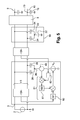
- a capacitor 15 models the parasitic impedances and / or the real impedances added for technical reasons, in the form of electronic components of the capacitor type, in particular between the terminal 10 of the circuit 4 and the frame 12. Another capacity can exist between the terminal 9 of the circuit 4 and the frame 12, as can be seen on the figure 3 .
- the terminal 10 of the circuit 4 is here the negative output terminal of the rectifier stage 8 and the electric circuit 4 has an internal mass 13 which is here formed by the terminal 10. Due to the existence of this capacitor 15, the common mode current i can flow from the circuit 4 to the chassis 12 and circulating in the earth, loop back into the power grid.
- the terminal 10 is alternately connected to the neutral of the electrical network and to one of the phases of this electrical network. In the case of a single-phase electrical network, the terminal 10 is selectively connected to the neutral or the phase of the electrical network.
- a voltage E is thus applied between the terminal 10 and the chassis 12 connected to the ground and, because of this voltage and the capacitor 15, the current flows from the terminal 10 to earth.
- the electrical line 5 is single-phase, comprising a conductor 17 forming the phase and another conductor 18 forming the neutral N, but the invention is not limited to a single-phase line.
- set 1 of the figure 3 comprises an electromagnetic interference filter 19 integrated in the circuit 4 and comprising a capacitor 22, here being a capacitor Y, mounted between the ground and a point 23 connected to each conductor 17 or 18 of the power line 5 via a capacitor 24, here being a capacitor X.
- an electronic component 21 is integrated in the circuit 4.
- This electronic component 21 is here configured to apply an electrical potential at a point 26, so that a voltage Vs is applied between this point 26 and the ground.
- the invention is however not limited to an electronic component applying an electrical potential, as will be seen later.
- This component 21 is an active filter configured to apply at a frequency equal to that of the voltage supplied by the electrical network an electrical potential from which the voltage Vs flows, this voltage Vs being applied between the point 26 and the earth and opposing the the voltage applied by the virtual voltage source 20.
- the resulting voltage applied to the impedances 6 and 16 is thus reduced, in particular canceled, so that the current flowing through these impedances 6 and 16 is reduced, in particular canceled.
- the point 26 is connected to each conductor 17 or 18 of the power line 5 via a respective capacitor 28 in the example described.
- Each capacitor 28 has in particular a capacity of the order of one ⁇ F.
- the potential applied by the electronic component 21 and from which the voltage Vs results is in the example considered generated solely on the basis of a signal representative of the common mode current i measured on the electrical line 5 upstream of the point 26.
- the component 21 is associated with a measurement device 124 of the common-mode current i running through the electrical line 5.
- this measuring device can measure a signal representative of the current in the conductor 17 forming the phase and a signal representative of the current in the conductor 18 forming the neutral, for example by means of a magnetic core, nanocrystalline or not.
- the electronic component 21 generates the potential resulting from the voltage Vs which is applied between the point 26 and the earth.
- the electronic component according to this second example of implementation. of the invention generates the voltage Vs both on the basis of a signal representative of the common mode current i traversing the power line 5 but also on the basis of a signal representative of the current Is flowing between the point 26 and the earth, this current Is can be called "output current of the electronic component 21".
- a second measuring device 45 disposed between the point 26 and the ground may make it possible to obtain a signal representative of said output current.
- the second subcomponent 61 forming the gain G2 is intended to stabilize the operation of the electronic component 21 at high and low frequencies by suppressing the oscillations occurring at these frequencies.
- the electronic component represented on the figure 4 receives on one of its inputs a signal representative of the common mode current i measured at a single location on the electrical line 5. This measurement is made here by the device 24 upstream of the point 26, that is to say between the connector 3 and capacitors 28.
- the electronic component 21 can generate the potential resulting from the output voltage Vs on the basis of two separate measurements representative of the common mode current i, these measurements being made in two different locations on the electrical line 5.
- a first measuring device 124 arranged similarly to the measuring device of the Figures 3 and 4 upstream of the point 26 on the power line 5, provides a signal forming the input of the first subcomponent 60 while a second measuring device 124, similar or not to the nanocrystalline magnetic core can be used for the first measuring device 124, may be disposed downstream of point 26.
- the second measuring device 124 is for example arranged on the electrical line 5 between the capacitors 28 and the rectifying stage 8.
- This second measuring device 124 provides at the input of a third subcomponent 62, generally forming a gain G3 , a signal representative of the common-mode current downstream of the capacitors 28.
- the output of the third subcomponent 62 may be compared with the signal provided by the measuring device 45 and the result of this comparison may form the true input of the second sub-component. component 61.
- the gain G3 of the third subcomponent 62 may be unitary and add to the component 21 a feedback control.
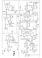
- the electronic component 21 comprises an input stage 30 receiving as input the voltage measured by a conductor 31 wound around the magnetic core of the measuring device 124.
- This input voltage is representative of the value of the common mode current i in the electrical line 5.
- An example of a measuring device 124 will be described later in connection with the Figures 12 to 19 .
- the stage 30 serves to amplify the voltage measurement thus performed while filtering the high frequencies.
- the output of this stage 30 then drives a stage 32 of summation of the signal coming from the stage 30 and a signal representative of the output current of the electronic component 21.
- This stage 32 makes it possible to control the output current Is at G1 gain product of the first subcomponent 60 and the common-mode current measured by the measuring device 124.
- stage 33 The output of the stage 32 then attacks a stage 33 forming a band pass amplifier.
- This stage 33 serves to increase the overall gain of the loop formed in this example by the electronic component 21, and to cut the low and high frequencies.
- the output of the stage 33 drives a high voltage output stage 34 which comprises in the example described two amplifiers 35 and 36.
- Each of these amplifiers 35 or 36 generates a voltage from a signal derived from the measurement made by the device 24.
- the two amplifiers 35 and 36 may be identical or different, and generate or not the same voltage.
- the first and the second voltage for example, both have an amplitude of about 300 V.
- the first amplifier 35 comprises, as can be seen, an inverter assembly 40.
- a first voltage is applied between the point 26 and the internal mass 42 of the electronic component 21 by the second amplifier 36 while a second voltage of opposite sign is applied between the ground and the internal mass 42 of the electronic component 21 by the first amplifier 35.
- the difference between these two voltages corresponds to the voltage applied by the electronic component 21 between the point 26 and the earth to reduce, better cancel, the common mode current i.
- a single amplifier can be used to form the stage 34 generating the voltage Vs.
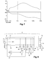
- the figure 7 represents the Bode diagram of the electronic component 21 which has just been described with reference to the figure 6 .
- the gain in dB is positive for frequencies between about 5 Hz and 1 kHz. It is also noted that the electronic component has a gain of 31 dB between 50 Hz and 60 Hz, substantially at the mains frequency, and a low phase margin when the gain in dB vanishes. Around 5 Hz, the phase margin in this example is 115 ° while around 1 kHz, the phase margin is -105 °.
- the voltage Vs results from a potential applied by the electronic component 21 which is generated on the basis of three inputs.
- the first input is the signal representative of the common mode current i measured upstream of the capacitors 28 on the power line
- the second input is the value of the output current Is flowing between the point 26 and the earth, as according to the example of the figure 5 .
- the third input is here formed by the value of a signal representative of the current flowing in one of the capacitors 22 of the electromagnetic interference filter 19.
- This third input is acquired using a measuring device 47 connected in series with said capacitor 22 and is processed by the third subcomponent 62 which allows feedback control.
- this third subcomponent 62 is then compared to the signal representative of the output current Is measured by the device 45, then the result of said comparison is received at the input of the second subcomponent 61.
- the Figures 3 to 8 relate to an electronic component 21 injecting at point 26 an electrical quantity which is an electric potential, that is to say that the electronic component 21 behaves as a voltage source.
- the electronic component 21 may be configured to inject an electric current at point 26, this component 21 behaving as a current source.
- the figure 9 represents a variant of the first example of implementation of the invention of the figure 3 differing only in that the electronic component 21 injects a current and not an electric potential.
- the third subcomponent 62 of the examples of figures 10 and 11 allows to implement a feedback.
- the power line 5 may be intended to be traversed by an alternating current. In case of anomaly, it can also be crossed by a common mode current.
- the common mode current can correspond to the resultant sum, in other words the algebraic sum, of currents flowing in several Conducting elements of the power line 5.
- the current is the resultant of the currents flowing in the phase 17 and the neutral 18 of the power line 5.
- Said magnetic flux generating means 126 comprise, in particular, a magnetic toroid 128, configured to be traversed by a magnetic flux coming from the current flowing in said electrical line 5.
- Said magnetic torus 128 consists, for example, of a magnetic material having a maximum relative permeability ⁇ r of between 5000 and 150,000, in particular of the order of 15,000 and / or a coercive field Hc of between 1 and 3 A / m. It may in particular be ferrite or amorphous materials.
- the torus 128 is configured to be traversed by said electrical line which forms a primary winding 127.
- said primary winding 127 comprises a turn.
- the magnetic core 128 is configured so that said primary winding passes rectilinearly through said core 128.
- Said magnetic flux generation means 126 comprise a secondary winding 130, wound around said torus 128, for generating a magnetic flux flowing through said core from a reference current.
- Said measuring device 124 further comprises, for example, an oscillator 132 generating said reference current through the secondary winding.
- Said oscillator is here connected on the one hand to a first terminal of the secondary winding 128 and on the other to a second terminal of said secondary winding 128, second terminal to which is connected a resistor 133 of said measuring device 124.
- Said resistor 133 is located between said second terminal and the ground.
- Oscillator 132 generates, for example, a square-type voltage alternately taking the two values + Vmax and -Vmax.
- the oscillator is here configured to go from + Vmax to -Vmax and reciprocally as soon as a maximum or a minimum current Ip + or Ip- in the secondary winding 130 is reached.
- the resistor 133 makes it possible to adjust the oscillations delivered to the second winding 130, in particular the peak current values Ip + or Ip- of the second winding 130.
- Said measuring device 124 in particular said oscillator 132 and said secondary winding 130 are configured to saturate said torus 128, under the action of the peak current.
- the current in the secondary winding 130 has rising up 134 and down 136 phases alternating with each other.
- the current generated in the secondary winding 130 corresponds to an unsaturated state of the core 128.
- the current increases or decreases relatively slowly.
- the current generated in the secondary winding corresponds to a saturated state of the magnetic core 128 and the current increases or decreases relatively fast.
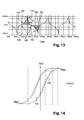
- FIG. figure 14 The corresponding cycle of magnetization and demagnetization of torus 128 is illustrated in FIG. figure 14 in the event of presence or absence of a current flowing in the primary winding.
- the solid line curve is the maximum magnetization curve.
- the curve 144 corresponds to the case where there is no current flowing in the primary winding.
- the extreme values of the induction correspond to zones of saturation of the material.
- the extreme values are equal in absolute value.
- This translates into the curve of the figure 13 by extreme values Ip +, Ip- of current flowing in the secondary winding which are also equal in absolute value and of opposite sign.
- This again results in an equality of the surfaces S1 and S2, located respectively between the abscissa and the positive portion of the ascending and descending phases 134, 136 and between the abscissa and the negative portion of the ascending and descending phases. , 136, that is to say, by a zero average value of the current flowing in said secondary winding.
- the curve 146 corresponds to the case in which a current is introduced into the primary winding. With respect to curve 144, curve 146 is shifted to positive induction values as shown. The saturation level of the magnetic material is higher in the positive values than in the negative values when the primary current generates a positive magnetomotive field.
- the saturation level of the magnetic material is higher in the negative values than in the positive values when the primary current generates a negative magnetomotive field.
- the curve 146 would be shifted to the negative induction values.
- the presence of a current in the primary winding 127 changes the magnetic state of the torus 128, which causes a change in the magnetization cycle and demagnetization of the core 128 and the secondary current.
- the secondary current values 130 make it possible to reach a saturation of the torus 128.
- figures 14 and 15 illustrate the interest of the saturation of the torus. Indeed, it can be seen that, thanks to this phenomenon, the amplitude of induction variation changes significantly as a function of the level of current flowing in the primary winding. In this way, the accuracy of the measurement is improved.
- the current flowing in the secondary winding is sufficiently high.
- the maximum current in absolute value flowing in said secondary winding is of the order of 100 mA with a good saturation of the core 128.
- the current flowing in the primary winding 127 may be of variable type.
- the current may have a frequency of 50 Hz.
- the frequency of this oscillator In order for the frequency of the oscillator to make it possible to obtain measurements of this current flowing in the primary winding 127, it is necessary that the frequency of this oscillator be much greater. that of the current flowing in said primary winding, in particular at least 10 times higher, for example 100 times higher. This makes it possible to reconstitute the primary current in a sufficiently faithful manner for its exploitation.
- the frequency of the oscillator 132 can be between 1 and 20 kHz. In particular, the frequency of the oscillator 132 may be 7 kHz to allow the measurement of a current of frequency 50 Hz to the primary. In other words, it is sought to reproduce the waveform of the primary current 127 with for example an error of 5 to 10% on the peak values.
- the primary winding 127 could have more than one turn.
- the secondary winding 130 then has a corresponding number of turns.
- the measuring device 124 comprises digital processing means 151 making it possible to obtain the value of the current flowing in said primary winding 127 according to the current flowing in the secondary winding 130.
- the value of the current is directly outputted. in high school as presented in figure 13 to a microcontroller or a digital circuit.
- the value of the primary current is deduced by a signal processing.
- the device according to this first variant gives a less efficient result in terms of linearity with respect to the variants that follow.
- high primary current values 127 bring the curve 146 closer to the extremal value + Bsat if the magnetomotive field is positive or the extreme value -Bsat if the magnetomotive field generated is negative.
- torus 128 is far from its neutral magnetic state, corresponding for example to curve 144 in figure 14 or at curve 138 in figure 13 , a reliable measurement of the primary current is no longer assured.
- the measuring devices 124 comprise an integrator-comparator module 150 delivering an output current, referred to as the primary current image, which is a function of the common-mode current to be measured. .
- the module 150 integrates the current from the secondary winding 130 and compares its average value with a zero value.
- the integrator-comparator module 150 delivers a current which is a function of the difference between the average value of the current at the secondary 130 and a zero value. For this purpose, this difference is greatly amplified, for example with a gain greater than 70 dB.
- the module 150 is configured to modify its output current as long as the difference is not substantially zero.
- the measuring device 124 further comprises means for compensating the flux generated in the core 128 by the current flowing in said primary winding 127, from the current delivered by said integrator-comparator module 150.
- the torus 128 is constantly reduced to a neutral magnetic state
- the average value of the secondary current is constantly reduced to a zero value
- the current delivered by the module 150 corresponds to the current flowing through the primary winding 127, in other words to the current common mode to measure.
- the module 150 and the flux compensation means define a servo loop controlling the magnetic state of the core 128.
- Said integrator-comparator module 150 is connected to said secondary winding 130.
- said integrator-comparator module 150 comprises an inverting input, connected to said second terminal of the secondary winding 130, in particular via a resistor 166, and a non-inverting input connected to ground.
- said compensating means correspond to a third winding 152, wound around said torus 128.
- the measuring means are configured so that said third winding 152 generates in the torus a magnetic flux, said compensation flux, opposite to that generated by said primary winding; the compensation flux being generated from the current delivered by the integrator-comparator module 150.
- Said third winding 152 is connected to the output of the integrator-comparator module 150 so that said third winding is traversed by the image current of the primary current.
- the terminal of the third winding 152 opposite to that connected to the integrator-comparator module 150 is connected to an output resistor 154 itself connected by its opposite terminal to ground.
- the voltage V OUT at the output terminal is thus equal to the product of the resistance Rs of said output resistor 154 and the current intensity quotient flowing in the primary winding 127 by the number of revolutions N of said third winding 152.
- the current Ie of the current flowing in the primary winding 127 is available by a simple measurement of the voltage at said output terminal 153.
- V ⁇ OUT Rs ⁇ Ie / NOT
- the third variant is illustrated in figures 16 and 17 .
- the torus 128 is illustrated schematically. It will also be noted that the primary winding has not been illustrated at figure 17 .
- said compensation means correspond to the secondary winding 130.
- An output of the integrator-comparator module 150 is connected to the secondary winding 130 and said measuring device 124 is configured so that the integrator-comparator module 150 generates a current flowing in the secondary winding 130 so as to compensate the flux generated by the primary winding 127.
- the magnetic flux generated in the core 128 by the current flowing in the primary winding 127 is no longer compensated by a flow generated by a current flowing through a third coil.
- the measuring devices 124 are configured so that the compensation flux is generated directly by a compensation current flowing through the secondary winding 130. In this variant, it is therefore not necessary to use a third winding 152.
- the oscillator 132 comprises an operational amplifier 156 and a voltage divider bridge comprising two resistors 158, 160.
- the midpoint of said voltage divider is connected to the non-inverting input of said operational amplifier 156.
- the output of the Operational amplifier 156, the terminal of one of the resistors 158 opposite the midpoint of said voltage divider and one of the terminals of the second winding 130 are at the same potential.
- the other 160 of the resistors of said voltage divider bridge is connected to ground.
- the integrator-comparator module 150 comprises an operational amplifier 162 and an RC bridge comprising a capacitor 164 and a resistor 166.
- the non-inverting input of said operational amplifier 162 is connected to ground. Its inverting input is connected to the midpoint of the RC bridge.
- the measuring device 124 comprises a resistor 135, called parameterization.
- One of the terminals of said measuring resistor is set to the same potential as the inverting input of the operational amplifier 156 of the oscillator 132, the terminal of the secondary winding 130 opposite to that connected to the output of said operational amplifier 156 of the oscillator 132, and the terminal of the resistor 166 of the RC bridge opposite the midpoint of said RC bridge.
- the other of the terminals of said measuring resistor 135 is set to the same potential as the output of said operational amplifier 162 of the integrator-comparator module 150, the terminal of the capacitor 164 of the RC bridge opposite to the midpoint of said RC bridge, and a point output 170.
- said measuring resistor 135 plays a dual role.
- the resistor 135 makes it possible to parameterize the oscillator 132, in particular the peak values Ip +, Ip- of the current at the secondary 130.
- the resistor 135 connects the second winding 130 to the output of the module integrator-comparator 150 for the circulation of the compensation current.
- Said measuring resistor 135 serves as an output resistor in the sense of the configuration of the embodiment of the figure 12 .
- a measurement of the voltage at the output point 170 will give the value of the current flowing in the primary winding 127.
- the resistor 135 can take only one value, it must respect a compromise between the specifications of the oscillator 132 and those related to the measurement of the voltage at the point of exit 170.
- the measuring device 124 comprises a resistance 169, called adjustment, placed between a terminal of the secondary winding 130, located between said secondary winding 130 and said oscillator 132, and a mass of said device 124.
- the adjustment resistance 169 makes it possible to adapt the characteristics of the oscillator 132, especially with a view to ensuring the saturation of the torus 128.
- the capacitor 180 makes it possible to eliminate a DC component in the current delivered to the adjustment resistor 169.
- the adjustment resistor 169 receives only the oscillating current determined by the oscillator 132.
- the measuring device 124 furthermore comprises a resistor 168, called a measurement resistor, which serves as an output resistor in the sense of the configuration of the embodiment of the figure 12 .
- figure 17 presents a developed electrical diagram, unlike the figure 16 which presents a semi-developed electrical scheme.
- Some elements of the variant illustrated in figure 17 can be integrated in a similar way in the variant of the figure 16 , in particular a current amplifier 172 and a resistor 174 of the oscillator 132, and a current amplifier 178 of the integrator-comparator module 150, as well as a filtering module 182, means 194 for adjusting the voltage range output signal, a fictitious mass generator 184, and securing means 193, 195, 196 of the operation of the oscillator.
- the output of the operational amplifier 156 of the oscillator 132 is for example connected to an input of the current amplifier 172.
- the output of said current amplifier 172, the terminal of one of the resistors 158 opposite the midpoint of said voltage divider and one of the terminals of the second winding 130 are at the same potential.
- the oscillator 132 may comprise the resistor 174, a first terminal of which is connected to the inverting input of the operational amplifier 156 of said oscillator 132.
- the output of the operational amplifier 162 of the integrator-comparator module 150 is for example connected to an input of the current amplifier 178.
- One of the terminals of said measurement resistor 168 is set to the same potential as the output of said amplifier current 178, the terminal of the capacitor 164 of the RC bridge of the integrator-comparator module 150 opposite the midpoint of said RC bridge, and the exit point 170.
- the other terminal of the measurement resistor 168 is set to the same potential as a second terminal of the resistor 174, the terminal of the secondary winding 130 opposite to that connected to the output of said current amplifier 152 of the oscillator 132 , and the terminal of the resistor 166 of the RC bridge of the integrator-comparator module 150 opposite to the midpoint of said RC bridge.
- This terminal is also at the same potential as one of the terminals of the adjustment resistor 169, here via a capacitor 180.
- the measuring device 124 may further comprise a filter module 182, connecting the output point 170 to a voltage measuring point 170 '.
- Said filtering module 182 is configured to eliminate from the signal the ripples coming from the oscillator 132.
- the measuring means may further comprise means 194 for adjusting the voltage range of the signal. available at the point of exit 170 'of the device.
- the adjustment means 194 is configured so that the output voltage is a positive voltage range determined from a Vsup power supply.
- a primary current of -100 mA corresponds to an output voltage Vout of 0V
- a primary current of 0 mA corresponds to an output voltage Vout of value V sup 2
- a primary current of 100 mA corresponds to an output voltage Vout of value Vsup.
- the supply Vsup may correspond to the supply of this control unit.
- Various means may also be used to make the measurement more reliable, in particular by ensuring that a current that is as symmetrical as possible in the secondary winding 130 can be obtained in the event of absence of current flowing in the primary winding 127. by this means a current for which the surfaces S1 and S2 mentioned above are as close as possible, with a minimum of error, in particular of offset type error.
- the measuring device 124 may be connected to a dummy mass 184. More specifically, the resistor 160 of the voltage divider bridge of said oscillator 132, the adjustment resistor 169 and / or the inverting input of the operational amplifier 162 of the integrator-comparator module 150 may be connected to said fictitious mass 184.
- the purpose of the fictitious mass generator 183 is to generate two symmetrical power supplies of values that are as identical as possible, in order to limit as much as possible the amplitude dissymmetries of the oscillator that affect the offset of the measurement.
- Said dummy mass generator 184 comprises an operational amplifier 185 whose output is connected to said dummy mass by a current amplifier 186.
- Said dummy mass generator 184 further comprises a voltage divider bridge 188 whose midpoint is connected to the earth. non-inverting input of the operational amplifier 185.
- the ends of the voltage divider bridge and the current amplifier are connected to a voltage supply source, in particular between 0 and 24V.
- Said dummy mass generator further comprises a resistor 190 placed between the dummy mass and the inverting input of said operational amplifier 185.
- Another solution that contributes to obtaining a current in the secondary winding 130 that is as symmetrical as possible in the event of absence of current flowing in the primary winding 127 consists in the use of the current amplifiers 172, 178, 186 output of the operational amplifiers 156, 162, 185 measuring means and / or dummy mass generator. In this way it will be possible to choose precise operational amplifiers while remaining of limited cost because having less current to deliver.
- said current amplifiers 172, 178, 186 include, for example, bipolar transistors.
- the operational amplifier or amplifiers 156, 162, 185 measuring means and or the dummy mass generator may be chosen so as to ensure transition times between values + Vmax and -Vmax their output voltage less than 50 ns. This is particularly the case for the operational amplifier 156 of the oscillator 132. In this way, it is avoided to provide a time dissymmetry to the generated signals illustrated in FIG. figure 11 .
- the measuring device 124 further comprises means 193, 195, 196 for securing the operation of the oscillator 132.
- the torus 128 saturates strongly continuously, which causes an increase in the frequency of the oscillator 132.
- a very high current primary is for example of the order 1A, see 10A.
- the frequency of the oscillator 132 can then be so high that the integrator-comparator module 150 may not be able to process the signal delivered by the oscillator.
- a high saturation of torus 128 can even lead to the cessation of oscillations. This causes instability of the detection device 100.
- the output voltage Vout then no longer corresponds with certainty to the primary current. There is a risk that the output voltage gives a value minus the primary current 127.
- the securing means 193, 195, 196 controls the frequency of the oscillator 132 to ensure that the oscillator is operating properly.
- the securing means consist of an inductance 196 in series between the oscillator 132 and the secondary winding 130.
- the inductance 196 is not wound on the torus 128 and is therefore substantially independent of the magnetic state of the torus.
- the inductor 196 ensures that the oscillator 132 oscillates even when the primary current is very high.
- the inductance 196 then replaces the secondary winding 130 which is too saturated, and determines the frequency of the oscillator 132.
- the inductor 196 provides an oscillation frequency F max which is compatible with the integrator module. Comparator 150.
- the output voltage Vout is stabilized at a corresponding voltage which indicates that the primary current is very high or out of the measurement range of the device.
- the securing means consist of measuring means 193, 195 of the frequency of the oscillator 132 as illustrated in FIG. figure 19 .
- the oscillator 132 operates in the design frequency range.
- the figure 19 corresponds to the variant of the figure 15 wherein inductance 196 is replaced by transistor 193 and resistor 195.
- the measuring means may comprise a transistor 193 whose gate voltage corresponds to the voltage across the resistor 160 connected between the ground and the non-inverting input of the operational amplifier 156 of the oscillator 132.
- the drain of the transistor 193 is connected by a resistor 195 to a power supply.
- This power supply is for example the same power supply Vsup used by the voltage adjustment device 194.
- the transistor 193 may be a MOSFET transistor.
- the drain-source voltage of the transistor 193 corresponds to the frequency Fout of the oscillator 132.
- the maximum oscillation frequency depends inter alia on the magnetic material of the torus 128, the number of turns of the secondary winding 130 and the primary current.
- the invention applies to a motor having a plurality of phases.
- the invention can be applied to other circuits 4 than to those on a vehicle.
- the measuring device 124 measures a current flowing in a primary winding 127. This current is in particular a resulting current.
- the core 128 is traversed by a plurality of conductive elements forming the primary winding 127 which produces this resulting current.
- the electrical circuit 4 is a H-bridge inverter / charger, for example such as the device disclosed in the French patent applications. FR2938711 or FR2944391 of the plaintiff, the contents of which are incorporated in this application.
Abstract
L'invention concerne un procédé de réduction du courant de mode commun circulant entre la masse interne d'un circuit électrique, notamment d'un circuit électrique d'un véhicule automobile, et la terre, lorsque de l'énergie électrique est échangée entre une unité de stockage d'énergie électrique du circuit électrique et une source d'énergie électrique externe audit circuit. Le procédé est tel que : ¢ on applique en un point d'injection du circuit à l'aide d'un composant électronique une grandeur électrique au moins fonction dudit courant de mode commun, ladite grandeur électrique étant appliquée de manière à réduire le courant de mode commun ; ¢ on obtient la valeur du courant de mode commun à l'aide d'un dispositif de mesure (124) comprenant : - un tore magnétique (128) configuré pour être traversé par une ligne électrique par l'intermédiaire de laquelle est échangée ladite énergie électrique, ladite ligne électrique formant un enroulement primaire (127) ; - un enroulement secondaire (130), enroulé autour dudit tore (128), pour générer un flux magnétique à partir d'un courant de référence ; - un oscillateur (132) pour générer le courant de référence à travers l'enroulement secondaire (130), le courant de référence étant configuré pour faire saturer ledit tore (128) ; le courant de mode commun correspondant à la valeur du courant de la ligne électrique obtenue à partir de la valeur moyenne du courant dans l'enroulement secondaire (130) sur une période d'oscillation parcourant un cycle complet de magnétisation et de démagnétisation du tore (128). The invention relates to a method for reducing the common mode current flowing between the internal ground of an electrical circuit, in particular an electrical circuit of a motor vehicle, and the ground, when electrical energy is exchanged between a electrical energy storage unit of the electrical circuit and a source of electrical energy external to said circuit. The process is such that: • an electrical quantity at least a function of said common mode current is applied to an injection point of the circuit using an electronic component, said electrical quantity being applied so as to reduce the common mode current; ¢ the value of the common mode current is obtained using a measuring device (124) comprising: - a magnetic core (128) configured to be crossed by an electrical line through which said electrical energy is exchanged, said electrical line forming a primary winding (127); - a secondary winding (130), wound around said core (128), to generate a magnetic flux from a reference current; - an oscillator (132) for generating the reference current through the secondary winding (130), the reference current being configured to saturate said core (128); the common mode current corresponding to the value of the current of the electric line obtained from the average value of the current in the secondary winding (130) over an oscillation period traversing a complete cycle of magnetization and demagnetization of the torus ( 128).
Description
La présente invention a pour objet la réduction du courant de mode commun circulant entre la masse interne d'un circuit électrique et la terre, lorsque de l'énergie électrique est échangée entre une source d'énergie électrique externe audit circuit et une unité de stockage d'énergie électrique dudit circuit. La source d'énergie électrique appartient par exemple à un réseau électrique étant notamment, mais non exclusivement, un réseau électrique dans lequel le neutre est relié directement à la terre.The object of the present invention is to reduce the common-mode current flowing between the internal mass of an electric circuit and the earth, when electrical energy is exchanged between a source of electrical energy external to said circuit and a storage unit. of electrical energy of said circuit. The source of electrical energy belongs for example to an electrical network including, but not limited to, an electrical network in which the neutral is connected directly to the earth.
Le réseau électrique peut être un réseau de tension alternative, polyphasée ou non, et cette tension est alors redressée pour alimenter l'unité de stockage d'énergie électrique du circuit électrique, par exemple une batterie.The electrical network may be an alternating voltage network, polyphase or not, and this voltage is then rectified to supply the electrical energy storage unit of the electrical circuit, for example a battery.
Le problème que l'invention vise à résoudre va être explicité en se référant à l'exemple non limitatif suivant. Le circuit électrique est par exemple embarqué dans un véhicule et peut comprendre un moteur électrique pour la propulsion électrique du véhicule. Le véhicule comprend encore un châssis.The problem that the invention aims to solve will be explained with reference to the following nonlimiting example. The electrical circuit is for example embedded in a vehicle and may include an electric motor for the electric propulsion of the vehicle. The vehicle still includes a chassis.
Lorsque l'unité de stockage d'énergie électrique est rechargée par le réseau électrique, le châssis est relié à la terre. Du fait de la présence de composants, parasites ou non, entre le circuit électrique et le châssis, un courant de mode commun peut circuler du circuit vers le châssis et se reboucler via la terre dans le réseau électrique.When the power storage unit is recharged by the power grid, the chassis is grounded. Due to the presence of components, parasites or not, between the electrical circuit and the chassis, a common mode current can flow from the circuit to the chassis and loop back via the earth in the power grid.
Un tel courant de mode commun est dangereux pour un utilisateur qui reposerait par ses pieds sur la terre et qui s'appuierait sur le châssis du véhicule.Such common mode current is dangerous for a user who would rest his feet on the ground and rely on the chassis of the vehicle.
Aussi, des normes existent pour limiter la valeur du courant de mode commun admissible entre la partie du circuit électrique en aval d'un redresseur et le châssis. Les normes européennes limitent ainsi à 3,5 mA la valeur maximale du courant de mode commun à une fréquence de 50 Hz.Also, standards exist to limit the value of the common mode current allowed between the part of the electrical circuit downstream of a rectifier and the chassis. The European standards limit the maximum value of the common mode current to a frequency of 50 Hz at 3.5 mA.
Pour respecter ces normes, il est connu de prévoir un transformateur d'isolement entre la partie du circuit en aval du redresseur et le châssis. Un tel transformateur peut être coûteux et son intégration dans un espace déjà contraint comme un véhicule peut être difficile.To comply with these standards, it is known to provide an isolation transformer between the part of the circuit downstream of the rectifier and the chassis. Such Transformer can be expensive and its integration into a space already constrained as a vehicle can be difficult.
Il est encore connu d'utiliser pour redresser le courant un composant à interrupteurs commandables, tel qu'un composant dit PFC (Power Factor Corrector), et d'implémenter des stratégies particulières pour la commande des interrupteurs. De telles stratégies peuvent conduire à un échauffement des interrupteurs et être très complexes.It is still known to use for rectifying the current a controllable switch component, such as a so-called PFC component (Power Factor Corrector), and to implement particular strategies for the control of the switches. Such strategies can lead to overheating of the switches and be very complex.
Dans le domaine des hautes fréquences, on connaît par la publication « A simplified active input EMI filter of common-mode voltage cancellation for induction motor drive » un filtre actif permettant de réduire le courant de mode commun aux hautes fréquences en injectant une tension en série dans le réseau électrique.In the field of high frequencies, there is known by the publication "A simplified active input EMI filter of common-mode voltage cancellation for induction motor drive" an active filter for reducing the common mode current at high frequencies by injecting a voltage in series in the electrical network.
On connaît également de la demande
En outre, un filtre actif utilise généralement une mesure du courant de mode commun afin d'adapter la stratégie de réduction de celui-ci. A cet effet, on prévoit un dispositif de mesure du courant de mode commun. Ce dispositif comprend par exemple un tore magnétique, comme divulgué dans la demande
L'invention vise à remédier aux inconvénients des solutions ci-dessus pour réduire le courant de mode commun entre le circuit électrique et la terre.The invention aims to overcome the disadvantages of the above solutions to reduce the common mode current between the electric circuit and earth.
L'invention y parvient, selon l'un de ses aspects, à l'aide d'un procédé de réduction du courant de mode commun circulant entre la masse interne d'un circuit électrique, notamment d'un circuit électrique d'un véhicule automobile, et la terre, lorsque de l'énergie électrique est échangée entre une unité de stockage d'énergie électrique du circuit électrique et une source d'énergie électrique externe audit circuit, procédé dans lequel :
- on applique en un point d'injection du circuit à l'aide d'un composant électronique une grandeur électrique au moins fonction dudit courant de mode commun, ladite grandeur électrique étant appliquée de manière à réduire le courant de mode commun ;
- on obtient la valeur du courant de mode commun à l'aide d'un dispositif de détection comprenant :
- un tore magnétique configuré pour être traversé par une ligne électrique par l'intermédiaire de laquelle est échangée ladite énergie électrique, ladite ligne électrique formant un enroulement primaire ;
- un enroulement secondaire, enroulé autour dudit tore, pour générer un flux magnétique à partir d'un courant de référence ;
- un oscillateur pour générer le courant de référence à travers l'enroulement secondaire, le courant de référence étant configuré pour faire saturer ledit tore ;
- an electrical quantity at least one function of said current is applied to an injection point of the circuit with the aid of an electronic component. common mode, said electrical magnitude being applied to reduce the common mode current;
- the value of the common mode current is obtained by means of a detection device comprising:
- a magnetic core configured to be traversed by a power line through which said electrical energy is exchanged, said power line forming a primary winding;
- a secondary winding, wound around said toroid, for generating a magnetic flux from a reference current;
- an oscillator for generating the reference current through the secondary winding, the reference current being configured to saturate said torus;
En faisant parcourir un cycle complet de magnétisation et de démagnétisation au tore, on s'assure que le tore atteint une saturation magnétique sur la période d'oscillation. Ainsi, la valeur moyenne du courant dans l'enroulement secondaire varie de façon significative, ce qui permet d'améliorer la précision de mesure du courant circulant dans la ligne électrique, qui correspond au courant de mode commun. Ceci sera mieux compris dans la description du mode particulier illustré sur les figures.By running a full cycle of magnetization and demagnetization torus, it is ensured that the torus reaches a magnetic saturation on the oscillation period. Thus, the average value of the current in the secondary winding varies significantly, which improves the measurement accuracy of the current flowing in the power line, which corresponds to the common mode current. This will be better understood in the description of the particular mode illustrated in the figures.
La source d'énergie électrique peut faire partie d'un réseau électrique et la grandeur électrique appliquée peut permettre de réduire le courant de mode commun à la fréquence du réseau électrique. La grandeur électrique appliquée peut également permettre de réduire le courant de mode commun aux dix premières harmoniques de cette fréquence du réseau électrique.The electrical power source can be part of an electrical network and the applied electrical magnitude can reduce the common mode current to the mains frequency. The applied electrical magnitude can also reduce the common mode current to the first ten harmonics of this frequency of the power grid.
On désignera ultérieurement par la suite par :
- « en amont du point d'injection », la partie de la ligne électrique disposée entre le réseau électrique et le point d'injection, et
- « en aval du point d'injection », la partie de la ligne électrique disposée entre le point d'injection et les composants du circuit électrique, notamment une unité de stockage d'énergie électrique.
- 'Upstream of the injection point' means the part of the electrical line between the electrical network and the injection point, and
- "Downstream of the injection point", that part of the electrical line disposed between the injection point and the components of the electrical circuit, in particular an electrical energy storage unit.
La grandeur électrique appliquée au point d'injection par le composant électronique peut être :
- un potentiel électrique, auquel cas une tension est appliquée par le composant électronique entre ledit point d'injection et la terre, ou
- un courant électrique, auquel cas ce courant circule entre ledit point d'injection et la terre.
- an electric potential, in which case a voltage is applied by the electronic component between said injection point and the earth, or
- an electric current, in which case this current flows between said injection point and the earth.
La grandeur électrique appliquée par le composant électronique lorsque le procédé ci-dessus correspond à une charge de l'unité de stockage d'énergie électrique du circuit depuis la source d'énergie électrique du réseau peut provoquer la génération d'un courant s'opposant au courant de mode commun circulant dans la ligne électrique en aval du point d'injection.The electrical magnitude applied by the electronic component when the above process corresponds to a load of the electrical energy storage unit of the circuit from the electrical energy source of the network can cause the generation of an opposing current common mode current flowing in the power line downstream of the injection point.
Lorsque le composant électronique applique un courant électrique au point d'injection, c'est ce courant qui est le courant généré mentionné ci-dessus.When the electronic component applies an electric current to the injection point, it is this current which is the generated current mentioned above.
Lorsque le composant électronique applique un potentiel électrique au point d'injection, l'application de ce potentiel provoque la génération du courant électrique mentionné ci-dessus.When the electronic component applies an electric potential to the injection point, the application of this potential causes the generation of the electric current mentioned above.
Le courant ainsi généré du fait de l'application de ladite grandeur électrique par le composant électronique peut avoir une valeur inférieure ou égale à la valeur du courant de mode commun circulant dans la ligne électrique en aval du point d'injection. Ce courant généré vaut par exemple en valeur absolue au moins 50%, mieux 60%, mieux 70%, mieux 80%, mieux 90%, mieux 95%, du courant de mode commun circulant dans la ligne électrique en aval du point d'injection.The current thus generated due to the application of said electrical quantity by the electronic component may have a value less than or equal to the value of the common-mode current flowing in the electrical line downstream of the injection point. This generated current is worth, for example, in absolute value at least 50%, better 60%, better 70%, better 80%, better 90%, better 95%, of the common-mode current flowing in the electrical line downstream of the point of contact. injection.
Plus la valeur du courant ainsi généré est proche de la valeur du courant de mode commun dans la ligne électrique en aval du point d'injection, plus la valeur du courant de mode commun circulant dans la ligne électrique en amont du point d'injection, c'est-à-dire entre autres dans le réseau électrique peut être réduite, par application de la loi des noeuds. Le courant généré du fait de l'application par le composant électronique de ladite grandeur électrique peut ainsi être une image aussi proche que possible du courant de mode commun circulant dans la ligne électrique en aval du point d'injection.The higher the value of the current thus generated is close to the value of the common-mode current in the electrical line downstream of the injection point, the higher the value of the common-mode current flowing in the electrical line upstream of the injection point. that is to say among others in the electrical network can be reduced, by application of the law of the nodes. The current generated due to the application by the The electronic component of said electrical quantity can thus be an image as close as possible to the common-mode current flowing in the electrical line downstream of the injection point.
Selon un premier mode de réalisation, la mesure du courant de la ligne électrique comprend l'utilisation :
- d'un module intégrateur-comparateur configuré pour délivrer un courant, dit image du courant au primaire, qui est fonction du courant traversant la ligne électrique, et
- des moyens pour compenser le flux généré par le courant traversant la ligne électrique à partir du courant délivré par ledit module.
- an integrator-comparator module configured to deliver a current, said primary current image, which is a function of the current flowing through the power line, and
- means for compensating the flow generated by the current flowing through the power line from the current delivered by said module.
Selon une variante, la mesure du courant de la ligne électrique (5) comprend l'utilisation de moyens (193, 195, 196) pour sécuriser le fonctionnement de l'oscillateur (132).Alternatively, the current measurement of the power line (5) comprises the use of means (193, 195, 196) for securing the operation of the oscillator (132).
Selon une variante, la compensation de flux comprend l'utilisation d'un troisième enroulement enroulé autour dudit tore, une sortie dudit module intégrateur-comparateur étant reliée audit troisième enroulement de façon à ce que ledit troisième enroulement soit parcouru par ledit courant image du courant au primaire.According to one variant, the flux compensation comprises the use of a third winding wound around said toroid, an output of said integrator-comparator module being connected to said third winding so that said third winding is traversed by said current image current. at primary.
Selon une variante, la compensation de flux comprend l'utilisation dudit enroulement secondaire, une sortie dudit module intégrateur-comparateur étant reliée audit enroulement secondaire de façon à ce que ledit enroulement secondaire soit parcouru par ledit courant image du courant au primaire.According to one variant, the flux compensation comprises the use of said secondary winding, an output of said integrator-comparator module being connected to said secondary winding so that said secondary winding is traversed by said image current of the primary current.
Selon une variante, la mesure du courant de la ligne électrique comprend l'utilisation d'une résistance, dite de paramétrage, ayant une première borne reliée à l'enroulement secondaire et à l'oscillateur, et une seconde borne reliée à une borne de sortie du dispositif et au module intégrateur-comparateur de façon à ajuster les caractéristiques de sortie du dispositif de détection et les caractéristiques de l'oscillateur.According to one variant, the measurement of the current of the electrical line comprises the use of a resistor, called a parameterization resistor, having a first terminal connected to the secondary winding and to the oscillator, and a second terminal connected to a terminal of output of the device and the integrator-comparator module so as to adjust the output characteristics of the detection device and the characteristics of the oscillator.
Selon une variante, la mesure du courant de la ligne électrique comprend l'utilisation d'une résistance, dite d'ajustement, ayant une première borne reliée à l'enroulement secondaire et à l'oscillateur et une seconde borne reliée à une masse dudit dispositif de façon à ajuster les caractéristiques de l'oscillateur.According to one variant, the measurement of the current of the electrical line comprises the use of a so-called adjustment resistor having a first terminal connected to the secondary winding and to the oscillator and a second terminal connected to a ground of said device so as to adjust the characteristics of the oscillator.
Selon une variante, la mesure du courant de la ligne électrique comprend l'utilisation d'une résistance, dite de mesure, ayant une première borne reliée à l'enroulement secondaire, et une seconde borne reliée à une borne de sortie du dispositif et au module intégrateur-comparateur de façon à ajuster les caractéristiques de sortie du dispositif de détection.According to one variant, the measurement of the current of the electrical line comprises the use of a so-called measurement resistor having a first terminal connected to the secondary winding, and a second terminal connected to an output terminal of the device and to the integrator-comparator module so as to adjust the output characteristics of the detection device.
Selon une variante, la mesure du courant de la ligne électrique comprend l'utilisation de moyens de filtrage dudit courant image du courant au primaire permettant d'obtenir un signal présentant un profil sensiblement identique à celui du courant traversant la ligne électrique.According to one variant, the measurement of the current of the electric line comprises the use of filtering means of said image current of the primary current to obtain a signal having a profile substantially identical to that of the current flowing through the power line.
Selon une variante, la mesure du courant de la ligne électrique comprend l'utilisation de moyens pour ajuster la plage de tension en sortie des moyens de filtrage.According to one variant, the measurement of the current of the electric line comprises the use of means for adjusting the voltage range at the output of the filtering means.
Selon une variante, le procédé comprend l'utilisation d'un générateur de masse fictive, les moyens de mesure étant reliés à ladite masse fictive.According to a variant, the method comprises the use of a dummy mass generator, the measuring means being connected to said dummy mass.
Selon un deuxième mode de réalisation, le composant électronique étant interposé entre la masse interne du circuit et la terre, ladite grandeur électrique est un potentiel électrique appliqué au point d'injection et dont résulte une tension appliquée entre ledit point d'injection et la terre. On applique la grandeur électrique entre la masse interne du circuit et la terre à l'aide dudit composant électronique de façon à former une tension, dite tension additionnelle ; cette tension additionnelle s'opposant à une tension appliquée par le réseau électrique entre la masse interne et la terre, de manière à réduire le courant de mode commun. La tension additionnelle appliquée dans le procédé, en particulier selon ce mode de réalisation, s'oppose à la tension appliquée par le réseau électrique entre la masse interne du circuit et la terre. La tension résultante entre le neutre du réseau électrique et la terre, mesurée aux bornes de l'impédance de la terre est ainsi réduite, d'où il ressort que le courant de mode commun est réduit. Le procédé suivant ce mode de réalisation peut comprendre des étapes de réduction du courant de mode commun telles que décrites dans la demande
Selon un troisième mode de réalisation, la grandeur électrique est appliquée en un point d'injection relié via au moins une impédance, notamment un condensateur, à la ligne électrique dudit circuit par l'intermédiaire de laquelle est échangée ladite énergie électrique.According to a third embodiment, the electrical quantity is applied at an injection point connected via at least one impedance, in particular a capacitor, to the electrical line of said circuit through which is exchanged said electrical energy.
Le point d'injection peut être relié à la ligne électrique via au moins un condensateur. La capacité de chaque condensateur peut être de l'ordre d'un µF.The injection point can be connected to the power line via at least one capacitor. The capacitance of each capacitor can be of the order of one μF.
En variante, le point d'injection peut être relié à la ligne électrique via au moins une bobine, ou via au moins une résistance ou via un transformateur ou via une association des composants qui viennent d'être cités.Alternatively, the injection point can be connected to the power line via at least one coil, or via at least one resistor or via a transformer or via a combination of the components just mentioned.
La ligne électrique peut être monophasée, auquel cas ledit point d'injection peut être relié :
- à la phase de la ligne électrique via au moins une impédance interposée entre ledit point et ladite phase, et
- au neutre de la ligne électrique via au moins une impédance interposée entre ledit point d'injection et ledit neutre.
- at the phase of the power line via at least one impedance interposed between said point and said phase, and
- in the neutral of the power line via at least one impedance interposed between said injection point and said neutral.
Dans une variante du cas d'une ligne électrique monophasée, le point d'injection peut être relié seulement à la phase, respectivement au neutre, de la ligne électrique via une impédance sans être relié au neutre, respectivement à la phase, de ladite ligne électrique.In a variant of the case of a single-phase electrical line, the injection point can be connected only to the phase, respectively to the neutral, of the electrical line via an impedance without being connected to the neutral, respectively to the phase, of said line electric.
En variante, la ligne électrique peut être triphasée, auquel cas le point d'injection peut être relié à chaque phase de la ligne électrique via au moins une impédance respective.Alternatively, the power line can be three-phase, in which case the injection point can be connected to each phase of the power line via at least one respective impedance.
Dans une variante du cas d'une ligne électrique triphasée, le point d'injection n'est pas relié à certaines phases de la ligne.In a variant of the case of a three-phase power line, the injection point is not connected to certain phases of the line.
Plus globalement, la ligne électrique peut être polyphasée, le nombre de phases pouvant être différent de trois.More generally, the power line can be polyphase, the number of phases can be different from three.
Selon une variante, la valeur du courant de la ligne électrique est mesurée à l'aide du dispositif de mesure positionné sur la ligne électrique entre la source d'énergie électrique du réseau et la ou les connexions de la ou des impédances avec la ligne électrique.According to one variant, the value of the current of the electric line is measured using the measuring device positioned on the electrical line between the electrical power source of the network and the connection or connections of the impedance or impedances with the power line. .
Selon un premier exemple de mise en oeuvre du troisième mode de réalisation, ladite grandeur électrique est appliquée par le composant électronique en fonction uniquement du courant de mode commun mesuré sur la ligne électrique, en particulier entre la source d'énergie électrique du réseau et la ou les connexions de la ou des impédances avec la ligne électrique.According to a first example of implementation of the third embodiment, said electrical quantity is applied by the electronic component as a function solely of the common-mode current measured on the electrical line, in particular between the power source of the network and the connection or connections of the impedance or impedances with the power line.
Le composant électronique peut, lorsque ladite grandeur est générée uniquement en fonction du signal représentatif du courant de mode commun mesuré en un seul emplacement de la ligne électrique, être assimilé à une boucle à un seul gain.The electronic component may, when said magnitude is generated solely as a function of the signal representative of the common mode current measured at a single location of the power line, be likened to a single gain loop.
Selon un deuxième exemple de mise en oeuvre du troisième mode de réalisation, ladite grandeur électrique est appliquée par le composant électronique en fonction du courant de mode commun mesuré sur la ligne électrique, notamment mesuré en amont du point d'injection, et du courant circulant entre ledit point d'injection et la terre.According to a second example of implementation of the third embodiment, said electrical quantity is applied by the electronic component as a function of the common-mode current measured on the electrical line, in particular measured upstream of the injection point, and of the current flowing between said injection point and the earth.
Lorsque le signal représentatif du courant de mode commun est mesuré en un seul emplacement selon ce deuxième exemple, le composant électronique peut être assimilé à une boucle à deux gains.When the signal representative of the common mode current is measured in a single location according to this second example, the electronic component can be likened to a two-gain loop.
Le procédé peut alors comprendre l'utilisation d'un composant électronique comportant :
- un premier sous-composant recevant en entrée le courant de mode commun mesuré sur la ligne électrique, et
- un deuxième sous-composant recevant en entrée le courant circulant entre ledit point d'injection et la terre,
- a first subcomponent receiving as input the common-mode current measured on the power line, and
- a second subcomponent receiving as input the current flowing between said injection point and the earth,
Le premier sous-composant peut être identique au composant électronique selon le premier exemple de mise en oeuvre du troisième mode de réalisation. En variante, le premier sous-composant peut fournir un gain de valeur plus importante que celle du gain fourni par le composant électronique selon le premier exemple de mise en oeuvre.The first subcomponent may be identical to the electronic component according to the first example of implementation of the third embodiment. Alternatively, the first subcomponent may provide a larger value gain than that of the gain provided by the electronic component according to the first exemplary implementation.
Le deuxième sous-composant peut fournir un deuxième gain permettant d'améliorer la stabilité aux hautes et basses fréquences en supprimant les oscillations induites par le premier sous-composant pour ces hautes et basses fréquences. Ce deuxième sous-composant peut ainsi asservir le courant généré du fait de l'application de ladite grandeur électrique à une valeur égale au produit du gain fourni par le premier sous-composant et du courant de mode commun mesuré.The second subcomponent may provide a second gain to improve high and low frequency stability by suppressing the oscillations induced by the first subcomponent for these high and low frequencies. This second subcomponent can thus slave the generated current due to the application of said electrical quantity to a value equal to the product of the gain provided by the first subcomponent and the measured common-mode current.
Selon une variante de ce deuxième exemple de mise en oeuvre de ce troisième mode de réalisation, ladite grandeur électrique est appliquée par le composant électronique en fonction :
- du courant de mode commun mesuré sur la ligne électrique entre la source d'énergie électrique et la ou les connexions de la ou des impédances,
- du courant de mode commun mesuré sur la ligne électrique entre la ou les connexions de la ou des impédances et l'unité de stockage d'énergie électrique, c'est-à-dire en aval du point d'injection et
- du courant circulant entre ledit point d'injection et la terre.
- common-mode current measured on the electrical line between the source of electrical energy and the connection or connections of the impedance or impedances,
- common-mode current measured on the electrical line between the connection (s) of the impedance (s) and the electrical energy storage unit, that is, downstream of the injection point and
- current flowing between said injection point and the earth.
Le courant de mode commun peut donc être mesuré en deux emplacements différents de la ligne électrique à l'aide par exemple d'un deuxième dispositif de mesure similaire à celui présenté précédemment.The common mode current can therefore be measured at two different locations of the power line using for example a second measuring device similar to that presented above.
La mesure du courant de mode commun en aval du point d'injection peut permettre de réaliser une rétro-action).The measurement of the common mode current downstream of the injection point may make it possible to perform a feedback).
L'invention concerne en outre un circuit électronique, comportant :
- une ligne électrique apte à être connectée à un réseau électrique de manière à permettre un échange d'énergie électrique entre une source d'énergie électrique dudit réseau et ledit circuit, et
- un composant électronique destiné à être relié d'une part à la ligne électrique, et apte à être relié d'autre part à la terre, le composant étant configuré pour appliquer en un point du circuit une grandeur électrique permettant de réduire le courant de mode commun lorsque de l'énergie électrique est échangée entre le circuit électrique et la source d'énergie électrique ; et
- un dispositif de mesure comprenant :
- un tore magnétique configuré pour être traversé par la ligne électrique par l'intermédiaire de laquelle est échangée ladite énergie électrique, ladite ligne électrique formant un enroulement primaire ;
- un enroulement secondaire, enroulé autour dudit tore, pour générer un flux magnétique à partir d'un courant de référence ;
- un oscillateur pour générer le courant de référence à travers l'enroulement secondaire, le courant de référence étant configuré pour faire saturer ledit tore ;
- an electrical line capable of being connected to an electrical network so as to allow an exchange of electrical energy between a source of electrical energy of said network and said circuit, and
- an electronic component intended to be connected on the one hand to the electrical line, and adapted to be connected on the other hand to earth, the component being configured to apply at a point of the circuit an electrical quantity for reducing the current of mode common when electrical energy is exchanged between the electric circuit and the source of electrical energy; and
- a measuring device comprising:
- a magnetic core configured to be traversed by the power line through which said electrical energy is exchanged, said power line forming a primary winding;
- a secondary winding, wound around said toroid, for generating a magnetic flux from a reference current;
- an oscillator for generating the reference current through the secondary winding, the reference current being configured to saturate said torus;
Le procédé selon l'invention peut présenter l'une quelconque de des caractéristiques suivantes compatibles avec les premier, deuxième et troisième modes de réalisation :
- le composant électronique est configuré de manière à asservir la valeur du courant de mode commun qu'il reçoit en entrée à une valeur de consigne prédéfinie, notamment zéro ;
- ladite grandeur électrique est un potentiel électrique appliqué au point d'injection et dont résulte une tension appliquée entre ledit point d'injection et la terre.
- the electronic component is configured so as to slave the value of the common-mode current that it receives as input to a predefined setpoint, in particular zero;
- said electrical quantity is an electric potential applied to the injection point and resulting in a voltage applied between said injection point and the ground.
L'invention concerne également des procédés obtenus par combinaison des modes de réalisationentre eux lorsqu'ils sont compatibles.The invention also relates to methods obtained by combining the embodiments with each other when they are compatible.
L'invention pourra être mieux comprise à la lecture qui va suivre d'un exemple non limitatif de mise en oeuvre de celle-ci et à l'examen du dessin annexé sur lequel :
- la
figure 1 représente de façon schématique un ensemble au sein duquel peut être mise en oeuvre l'invention, - la
figure 2 représente de façon schématique un modèle en mode commun, équivalent à l'ensemble de lafigure 1 , - la
figure 3 est une représentation similaire à celle de lafigure 1 dans laquelle un composant électronique selon un premier exemple de mise en oeuvre de l'invention est introduit, - les
figures 4 et 5 représentent de façon analogue à lafigure 3 deux variantes d'un composant électronique selon un deuxième exemple de mise en oeuvre de l'invention, - la
figure 6 représente le schéma électrique du composant électronique de lafigure 4 , - la
figure 7 est le diagramme de Bode de la fonction de transfert du composant électronique de lafigure 4 , - la
figure 8 représente de façon analogue auxfigures 3 à 5 un composant électronique selon un troisième exemple de mise en oeuvre de l'invention, et - les
figures 9 à 11 diffèrent respectivement desfigures 3 ,5 et 8 par le fait que le composant électronique forme une source de courant et non une source de tension. - la
figure 12 illustre de façon schématique un premier exemple de réalisation du dispositif de mesure servant à mesurer le courant de mode commun, - la
figure 13 illustre une courbe donnant, en fonction du temps, la variation d'un courant circulant dans ledit dispositif, en absence d'un courant de mode commun, - la
figure 14 est une courbe d'aimantation illustrant le fonctionnement dudit dispositif de mesure, en présence et en absence d'un courant de mode commun, - la
figure 15 reprend lafigure 11 pour comparer les courbes obtenues en présence et en absence d'un courant de mode commun, - la
figure 16 illustre de façon schématique un second exemple de réalisation du dispositif de mesure, - la
figure 17 illustre de façon schématique un troisième exemple de réalisation du dispositif de mesure, - la
figure 18 illustre de façon schématique un autre exemple de réalisation du dispositif de mesure. - la
figure 19 illustre de façon schématique un quatrième exemple de réalisation du dispositif de mesure,
- the
figure 1 schematically represents an assembly in which the invention can be implemented, - the
figure 2 schematically represents a common mode model, equivalent to the whole of thefigure 1 , - the
figure 3 is a representation similar to that of thefigure 1 in which an electronic component according to a first example of implementation of the invention is introduced, - the
figures 4 and5 represent in a similar way to thefigure 3 two variants of an electronic component according to a second example of implementation of the invention, - the
figure 6 represents the circuit diagram of the electronic component of thefigure 4 , - the
figure 7 is the Bode diagram of the transfer function of the electronic component of thefigure 4 , - the
figure 8 represents in a similar way toFigures 3 to 5 an electronic component according to a third example of implementation of the invention, and - the
Figures 9 to 11 differ fromfigures 3 ,5 and8 in that the electronic component forms a current source and not a voltage source. - the
figure 12 schematically illustrates a first embodiment of the measuring device for measuring the common-mode current, - the
figure 13 illustrates a curve giving, as a function of time, the variation of a current flowing in said device, in the absence of a common mode current, - the
figure 14 is a magnetization curve illustrating the operation of said measuring device, in the presence and absence of a common mode current, - the
figure 15 resumesfigure 11 to compare the curves obtained in the presence and absence of a common mode current, - the
figure 16 schematically illustrates a second embodiment of the measuring device, - the
figure 17 schematically illustrates a third embodiment of the measuring device, - the
figure 18 schematically illustrates another embodiment of the measuring device. - the
figure 19 schematically illustrates a fourth embodiment of the measuring device,
On a représenté à la
Cet ensemble 1 comprend une source d'énergie électrique 2 d'un réseau électrique apte à être branché via un connecteur 3 à un circuit électrique 4. Le circuit électrique 4 est dans l'exemple considéré embarqué sur un véhicule à propulsion hybride ou électrique, faisant alors partie du circuit électrique de propulsion de ce véhicule.This
Lorsque l'on souhaite charger une unité de stockage d'énergie électrique non représentée du circuit électrique 4, la source d'énergie électrique 2 fournit par exemple une tension alternative au circuit électrique 4. Dans l'exemple considéré, le réseau est triphasé et la tension aux bornes de la source d'énergie électrique 2 a une valeur efficace égale à 230 V. La fréquence de la tension est de 50 Hz dans l'exemple considéré. Le neutre N du réseau électrique est relié à la terre, et une impédance parasite 6 est interposée entre le neutre N et la terre.When it is desired to charge a not shown electrical energy storage unit of the
Le circuit électrique 4 comprend :
- une ligne électrique 5
reliant le connecteur 3 au reste ducircuit électrique 4, - des inductances 7, et
un étage 8 de redressement de la tension alternative fournie par la source d'énergieélectrique 2 et dont les bornes de sortie 9 et 10 sont parcourues par un courant continu.
- an
electrical line 5 connecting theconnector 3 to the rest of theelectrical circuit 4, -
inductances 7, and - a
stage 8 for rectifying the AC voltage supplied by the source ofelectrical energy 2 and whoseoutput terminals
L'étage de redressement 8 comprend par exemple des interrupteurs commandables tels que des transistors. L'étage 8 est par exemple un composant PFC, connu de l'homme du métier pour redresser une tension alternative, adapter la valeur de la tension redressée à la charge du circuit 4, et respecter les normes en vigueur quant à la valeur du facteur de puissance et à l'émission de courants harmoniques.The rectifying
Entre les bornes 9 et 10 de sortie de l'étage 8 est monté un condensateur 11. L'unité de stockage d'énergie électrique, qui est par exemple une batterie, peut être branchée en parallèle de ce condensateur 11. Cette batterie absorbe une puissance électrique par exemple supérieure à 100W, par exemple de l'ordre de 3kW quand le réseau électrique est monophasé, par exemple une puissance de l'ordre de 20 kW quand le réseau électrique est triphasé.Between the
L'ensemble 1 comprend encore un châssis métallique 12. En cas de défaut de la mise à la terre du châssis, ce dernier est potentiellement relié à la terre via une impédance 16. Cette impédance 16 correspond, dans le cas où le châssis fait partie d'un véhicule, à la résistance corporelle d'un utilisateur du véhicule lorsque ce dernier touche d'une part la carrosserie et d'autre part le sol.The
Dans l'application où l'ensemble 1 est embarqué sur un véhicule à propulsion électrique ou hybride, les inductances 7 correspondent par exemple alors aux enroulements des phases du stator d'un moteur électrique pour la propulsion d'un moteur électrique. Les enroulements 7 peuvent alors être reliés au réseau électrique selon l'enseignement de la demande
Une capacité 15 modélise les impédances parasites et/ou les impédances réelles ajoutées pour raisons techniques, sous forme de composants électroniques de type condensateurs, notamment entre la borne 10 du circuit 4 et le châssis 12. Une autre capacité peut exister entre la borne 9 du circuit 4 et le châssis 12, comme on peut le voir sur la
La borne 10 du circuit 4 est ici la borne négative de sortie de l'étage redresseur 8 et le circuit électrique 4 possède une masse interne 13 qui est ici formée par la borne 10. Du fait de l'existence de ce condensateur 15, du courant de mode commun i peut circuler du circuit 4 vers le châssis 12 et en circulant dans la terre, se reboucler dans le réseau électrique.The terminal 10 of the
Dans le cas où la source d'énergie électrique 2 du réseau électrique fournit une tension alternative polyphasée, et lors d'une séquence de fonctionnement des interrupteurs de l'étage 8 redresseur, la borne 10 est alternativement reliée au neutre du réseau électrique et à l'une des phases de ce réseau électrique. Dans le cas d'un réseau électrique monophasé, la borne 10 est reliée sélectivement au neutre ou à la phase du réseau électrique.In the case where the
Une tension E est ainsi appliquée entre la borne 10 et le châssis 12 relié à la terre et, du fait de cette tension et du condensateur 15, du courant circule de la borne 10 vers la terre.A voltage E is thus applied between the terminal 10 and the
La partie du circuit 4 en amont de la borne 10, et le réseau électrique, peuvent ainsi être assimilés à une source de tension virtuelle 20 appliquant alternativement entre la borne 10 et le châssis 12:
- une tension E nulle, et
- une tension E image de celle délivrée par le réseau au
circuit 4.
- a zero voltage E, and
- a voltage E image of that delivered by the network to the
circuit 4.
En conséquence, du courant de mode commun i circule à travers le condensateur 15 et les impédances 16 et 6 avant de se reboucler dans le réseau. On obtient ainsi le modèle en mode commun équivalent selon la
On va décrire en référence à la
Comparativement à l'ensemble représenté sur la
Comme on peut le voir sur la
Ce composant 21 est un filtre actif configuré pour appliquer à une fréquence égale à celle de la tension fournie par le réseau électrique un potentiel électrique dont découle la tension Vs, cette tension Vs étant appliquée entre le point 26 et la terre et s'opposant à la tension appliquée par la source de tension virtuelle 20. La tension résultante appliquée aux impédances 6 et 16 est ainsi réduite, notamment annulée, de sorte que le courant parcourant ces impédances 6 et 16 est réduit, notamment annulé.This
Le point 26 est relié à chaque conducteur 17 ou 18 de la ligne électrique 5 via un condensateur respectif 28 dans l'exemple décrit. Chaque condensateur 28 a notamment une capacité de l'ordre d'un µF. Le potentiel appliqué par le composant électronique 21 et dont résulte la tension Vs est dans l'exemple considéré généré uniquement sur la base d'un signal représentatif du courant de mode commun i mesuré sur la ligne électrique 5 en amont du point 26.The
Dans l'exemple considéré, le composant 21 est associé à un dispositif de mesure 124 du courant de mode commun i parcourant la ligne électrique 5. Dans le cas d'une ligne électrique 5 monophasée, ce dispositif de mesure peut mesurer un signal représentatif du courant dans le conducteur 17 formant la phase et un signal représentatif du courant dans le conducteur 18 formant le neutre, par exemple à l'aide d'un tore magnétique, nanocristallin ou non. Par calcul à partir de ces signaux représentatifs de courant, on peut déterminer la valeur d'un signal représentatif du courant de mode commun i. Sur la base de cette information, le composant électronique 21 génère le potentiel dont résulte la tension Vs qui est appliquée entre le point 26 et la terre.In the example considered, the
Comme représenté sur la
- Zinj l'impédance existant entre le
point 26 et la terre du fait de la présence de la tension Vs, - Zy l'impédance existant entre chaque conducteur 17, 18 et la terre du fait de la présence du condensateur 22 et de la ou les capacités
parasites 15, - Vac la tension aux bornes de la source d'énergie
électrique 2.

- Zinj the impedance existing between the
point 26 and the earth due to the presence of the voltage Vs, - Zy the impedance existing between each
conductor capacitor 22 and theparasitic capacitance 15, - Vac the voltage across the
power source 2.
On va maintenant décrire en référence aux
Contrairement au composant électronique de la
De façon schématique, on peut considérer que le composant électronique 21 forme ici une boucle à deux gains :
- un premier sous-
composant 60 se comportant comme un gain G1 amplifiant le signal représentatif du courant de mode commun i dans la ligne électrique 5 mesurépar le dispositif 24, et - un deuxième sous-
composant 61 se comportant comme un gain G2 amplifiant le signal représentatif du courant de sortie Is circulant entre lepoint 26 et la terre.
- a
first subcomponent 60 behaving as a gain G1 amplifying the signal representative of the common mode current i in thepower line 5 measured by thedevice 24, and - a
second subcomponent 61 behaving as a gain G2 amplifying the signal representative of the output current Is flowing between thepoint 26 and the earth.
Le deuxième sous-composant 61 formant le gain G2 a pour but de stabiliser le fonctionnement du composant électronique 21 aux hautes et basses fréquences en supprimant les oscillations se produisant à ces fréquences.The
Le composant électronique représenté sur la
Comme représenté sur la
Le deuxième dispositif de mesure 124 est par exemple disposé sur la ligne électrique 5 entre les condensateurs 28 et l'étage de redressement 8. Ce deuxième dispositif de mesure 124 fournit en entrée d'un troisième sous-composant 62, formant globalement un gain G3, un signal représentatif du courant de mode commun en aval des condensateurs 28. La sortie du troisième sous-composant 62 peut être comparée au signal fourni par le dispositif de mesure 45 et le résultat de cette comparaison peut former la véritable entrée du deuxième sous-composant 61.The
Le gain G3 du troisième sous-composant 62 peut être unitaire et ajouter au composant 21 un contrôle par rétro-action.The gain G3 of the
On va maintenant décrire en référence à la
Le composant électronique 21 comprend un étage d'entrée 30 recevant en entrée la tension mesurée par un conducteur 31 bobiné autour du noyau magnétique du dispositif de mesure 124. Cette tension d'entrée est représentative de la valeur du courant de mode commun i dans la ligne électrique 5. Un exemple de dispositif de mesure 124 sera décrit ultérieurement en relation avec les
L'étage 30 a pour rôle d'amplifier la mesure de tension ainsi effectuée tout en filtrant les hautes fréquences.The
La sortie de cet étage 30 attaque ensuite un étage 32 de sommation du signal issu de l'étage 30 et d'un signal représentatif du courant de sortie du composant électronique 21. Cet étage 32 permet de réaliser un asservissement du courant de sortie Is au produit du gain G1 du premier sous-composant 60 et du courant de mode commun mesuré par le dispositif de mesure 124.The output of this
La sortie de l'étage 32 attaque ensuite un étage 33 formant un amplificateur passe bande. Cet étage 33 a pour fonction d'augmenter le gain global de la boucle formée dans cet exemple par le composant électronique 21, et de couper les basses et les hautes fréquences.The output of the
La sortie de l'étage 33 attaque un étage de sortie haute tension 34 qui comprend dans l'exemple décrit deux amplificateurs 35 et 36.The output of the
Chacun de ces amplificateurs 35 ou 36 génère une tension à partir d'un signal issu à la base de la mesure effectuée par le dispositif 24. Les deux amplificateurs 35 et 36 peuvent être identiques ou non, et générer ou non une même tension. La première et la deuxième tension ont par exemple toutes deux une amplitude de 300 V environ.Each of these
Le premier amplificateur 35 comprend comme on peut le voir un montage inverseur 40.The
Avec les deux amplificateurs 35 et 36 représentés sur la
Dans un autre exemple non représenté, un seul amplificateur peut être utilisé pour former l'étage 34 générant la tension Vs.In another example not shown, a single amplifier can be used to form the
La
On constate que le gain en dB est positif pour des fréquences comprises entre environ 5 Hz et 1 kHz. On constate par ailleurs que le composant électronique présente un gain de 31 dB entre 50 Hz et 60 Hz, soit sensiblement à la fréquence du réseau électrique, et une marge de phase faible lorsque le gain en dB s'annule. Autour de 5 Hz, la marge de phase est dans cet exemple de 115° tandis qu'autour de 1 kHz, la marge de phase est de -105°.It is found that the gain in dB is positive for frequencies between about 5 Hz and 1 kHz. It is also noted that the electronic component has a gain of 31 dB between 50 Hz and 60 Hz, substantially at the mains frequency, and a low phase margin when the gain in dB vanishes. Around 5 Hz, the phase margin in this example is 115 ° while around 1 kHz, the phase margin is -105 °.
On va maintenant décrire en référence à la
Dans cet exemple, la première entrée est le signal représentatif du courant de mode commun i mesuré en amont des condensateurs 28 sur la ligne électrique, et la deuxième entrée est la valeur du courant de sortie Is circulant entre le point 26 et la terre, comme selon l'exemple de la
Contrairement à l'exemple de la
Cette troisième entrée est acquise à l'aide d'un dispositif de mesure 47 monté en série avec ledit condensateur 22 et elle est traitée par le troisième sous-composant 62 qui permet un contrôle par rétro-action.This third input is acquired using a
La sortie de ce troisième sous-composant 62 est ensuite comparée au signal représentatif du courant de sortie Is mesuré par le dispositif 45, puis le résultat de ladite comparaison est reçu en entrée du deuxième sous-composant 61.The output of this
Avec les mêmes notations que ci-dessus et en désignant par :
- Cyf2 la capacité du condensateur 22 de la
figure 8 en série avec le dispositif de mesure 47, - Cyf1 la capacité du condensateur 22 de la
figure 8 en parallèle avec le dispositif de mesure 47, et - Cor la fonction de transfert du troisième sous-
composant 62,

- Cyf2 the capacitance of the
capacitor 22 of thefigure 8 in series with the measuringdevice 47, - Cyf1 the capacitance of the
capacitor 22 of thefigure 8 in parallel with the measuringdevice 47, and - Cor the transfer function of the
third subcomponent 62,
Si on choisit le troisième sous-composant 62 de sorte que sa fonction de transfert prenne la valeur suivante : 
Alors l'équation donnant la valeur du courant de mode commun i en fonction de la tension fournie par la source d'énergie électrique 2 en présence du composant électronique de la 
Le composant électronique 21 selon la
- un contrôle en boucle ouverte avec rétro-action via le troisième sous-
composant 62 et le gain G2 fourni par le deuxième sous-composant 61 pour supprimer le courant de mode commun i, et - un contrôle via le premier sous-
composant 60 fournissant le gain G1 permettant de supprimer l'erreur résiduelle liée aux imprécisions par exemple sur les valeurs de Zy, Zybat, l'impédance de terre correspondant à la somme des impédances 6 et 16 de lafigure 1 , ou encore sur la valeur de la fonction de transfert du troisième sous-composant 62.
- an open loop control with feedback via the
third subcomponent 62 and the gain G2 provided by thesecond subcomponent 61 to suppress the common mode current i, and - a control via the
first subcomponent 60 providing the gain G1 for removing the residual error related to inaccuracies for example on the values of Zy, Zybat, the ground impedance corresponding to the sum of theimpedances figure 1 , or on the value of the transfer function of thethird subcomponent 62.
Les
En variante, comme représenté sur les
La
La
- par le fait que le composant électronique 21 injecte un courant et non un potentiel électrique, et
- par le fait que le deuxième sous-composant 61 a pour seule entrée la sortie du troisième sous-
composant 62, c'est-à-dire que le composant électronique qui génère le courant Is n'a par pour entrée le courant Is mais le courant de mode commun en amont et en aval dupoint d'injection 26.
- in that the
electronic component 21 injects a current and not an electric potential, and - in that the
second subcomponent 61 has as its only input the output of thethird subcomponent 62, that is to say that the electronic component which generates the current Is has for input the current Is but the common-mode current upstream and downstream of theinjection point 26.
La
- par le fait que le composant électronique 21 injecte un courant et non un potentiel électrique, et
- par le fait que le deuxième sous-composant 61 a pour seule entrée la sortie du troisième sous-
composant 62, c'est-à-dire que la génération par le composant électronique 21 du courant Is ne se fait pas avec ce même courant Is comme entrée mais avec comme entrées le courant de mode commun en amont dupoint d'injection 26 et le courant circulant dans le condensateur 22 dufiltre 19.
- in that the
electronic component 21 injects a current and not an electric potential, and - in that the
second subcomponent 61 has as its sole input the output of thethird subcomponent 62, that is to say that the generation by theelectronic component 21 of the current Is is not done with this same current Is as input but with as inputs the common-mode current upstream of theinjection point 26 and the current flowing in thecapacitor 22 of thefilter 19.
Le troisième sous-composant 62 des exemples des
Un exemple de dispositif 124 de mesure du courant de mode commun va maintenant être décrit plus précisément dans ce qui suit, en faisant d'abord référence à la
En mode normal, la ligne électrique 5 peut être destinée à être parcourue par un courant alternatif. En cas d'anomalie, elle pourra aussi être traversée par d'un courant de mode commun. Le courant de mode commun peut correspondre à la somme résultante, autrement dit la somme algébrique, de courants circulant dans plusieurs éléments conducteurs de la ligne électrique 5. En particulier, dans une installation monophasée, le courant est la résultante des courants circulant dans la phase 17 et le neutre 18 de la ligne électrique 5. Ainsi, dans ce qui suit, par l'expression « courant parcourant la ligne électrique 5 » on désigne le courant résultant parcourant les éléments conducteurs de la ligne électrique 5.In normal mode, the
Lesdits moyens 126 de génération du flux magnétique comprennent, notamment, un tore magnétique 128, configuré pour être parcouru par un flux magnétique provenant du courant circulant dans ladite ligne électrique 5.Said magnetic flux generating means 126 comprise, in particular, a
Ledit tore magnétique 128 est constitué, par exemple, d'un matériau magnétique présentant une perméabilité relative maximale µr comprise entre 5000 et 150000, notamment de l'ordre de 15000 et/ou un champ coercitif Hc compris entre 1 et 3 A/m. Il pourra en particulier s'agir de ferrite ou de matériaux amorphes.Said
Le tore 128 est configuré pour être traversé par ladite ligne électrique qui forme un enroulement primaire 127. De préférence, ledit enroulement primaire 127 comprend une spire. On entend par là que le tore magnétique 128 est configuré pour que ledit enroulement primaire passe de façon rectiligne à travers ledit tore 128.The
Lesdits moyens 126 de génération du flux magnétique comprennent un enroulement secondaire 130, enroulé autour dudit tore 128, pour générer un flux magnétique parcourant ledit tore à partir d'un courant de référence.Said magnetic flux generation means 126 comprise a secondary winding 130, wound around said
Lesdits dispositif de mesure 124 comprennent en outre, par exemple, un oscillateur 132 générant ledit courant de référence à travers l'enroulement secondaire. Ledit oscillateur est ici relié d'une part à une première borne de l'enroulement secondaire 128 et de l'autre à une seconde borne dudit enroulement secondaire 128, seconde borne à laquelle est reliée une résistance 133 desdits dispositif de mesure 124. Ladite résistance 133 est située entre ladite seconde borne et la masse. L'oscillateur 132 génère, par exemple, une tension de type carré prenant alternativement les deux valeurs +Vmax et -Vmax. L'oscillateur est ici configuré pour passer de +Vmax à -Vmax et réciproquement dès qu'un maximum ou un minimum de courant Ip+ ou Ip- dans l'enroulement secondaire 130 est atteint. La résistance 133 permet d'ajuster les oscillations délivrées au second enroulement 130, notamment les valeurs de courant crête Ip+ ou Ip- du second enroulement 130.Said measuring
Lesdits dispositif de mesure 124, en particulier ledit oscillateur 132 et ledit enroulement secondaire 130 sont configurés pour saturer ledit tore 128, sous l'action du courant crête.Said measuring
On décrit en référence à la
Le cycle correspondant de magnétisation et de démagnétisation du tore 128 est illustré à la
La courbe en trait plein est la courbe de magnétisation maximale.The solid line curve is the maximum magnetization curve.
La courbe 144, illustrée par des tirets, correspond au cas où il n'y a pas de courant circulant dans l'enroulement primaire. Dans ce cas, on constate que les valeurs extrêmes de l'induction correspondent à des zones de saturation de la matière. On constate également que les valeurs extrêmes sont égales en valeur absolue. Ceci se traduit sur la courbe de la
La courbe 146, illustrée par des tirets, correspond au cas dans lequel, on introduit un courant dans l'enroulement primaire. Par rapport à la courbe 144, la courbe 146 est décalée vers les valeurs positives d'induction comme représenté. Le niveau de saturation du matériau magnétique est plus élevé dans les valeurs positives que dans les valeurs négatives quand le courant primaire génère un champ magnétomoteur positif.The
Inversement, le niveau de saturation du matériau magnétique est plus élevé dans les valeurs négatives que dans les valeurs positives quand le courant primaire génère un champ magnétomoteur négatif. Dans ce cas, par rapport à la courbe 144, la courbe 146 serait décalée vers les valeurs négatives d'induction.Conversely, the saturation level of the magnetic material is higher in the negative values than in the positive values when the primary current generates a negative magnetomotive field. In this case, with respect to the
Autrement dit, la présence d'un courant dans l'enroulement primaire 127 modifie l'état magnétique du tore 128, ce qui entraîne une modification du cycle de magnétisation et de démagnétisation du tore 128 et du courant au secondaire.In other words, the presence of a current in the primary winding 127 changes the magnetic state of the
On a illustré à la
On retrouve dans la courbe 148 la dissymétrie de la courbe 146 de magnétisation et démagnétisation. Les vitesses d'évolution du courant au secondaire sont beaucoup plus élevées dans la partie positive que dans la partie négative, car on sature mieux dans la partie positive que dans la partie négative. Ceci permet d'expliquer la différence entre les surfaces S1, S2 des parties positives et négatives. Autrement dit, la valeur moyenne du courant circulant dans l'enroulement secondaire n'est plus nulle. Cette valeur moyenne dépend du courant qui circule dans l'enroulement primaire.We find in the
Par conséquent, lorsque le courant de l'enroulement primaire 127 varie, la valeur moyenne du courant au secondaire 130 sur une période d'oscillation varie proportionnellement. Ainsi, en observant le courant au secondaire, on remonte à la valeur du courant dans l'enroulement primaire 127. On dispose de la sorte d'une solution permettant de mettre en évidence la présence et même de quantifier la valeur du courant circulant dans l'enroulement primaire 127. En outre, grâce aux moyens 126 de génération de flux magnétique, une mesure du courant dans l'enroulement primaire 127 est obtenue tout en ayant une isolation galvanique entre le circuit 4 du véhicule et le circuit mis en oeuvre pour la mesure.Therefore, when the current of the primary winding 127 varies, the average value of the secondary current 130 over an oscillation period varies proportionally. Thus, by observing the current at the secondary, it goes back to the value of the current in the primary winding 127. It is in this way a solution to highlight the presence and even to quantify the value of the current flowing in the primary winding 127. In addition, thanks to the magnetic flux generation means 126, a measurement of the current in the primary winding 127 is obtained while having a galvanic isolation between the
Il est préférable que les valeurs de courant au secondaire 130 permettent d'atteindre une saturation du tore 128. Les
Pour garantir un bon niveau de saturation du matériau magnétique, il est nécessaire que le courant circulant dans l'enroulement secondaire soit suffisamment élevé. Par exemple, le courant maximum en valeur absolue circulant dans ledit enroulement secondaire est de l'ordre de 100 mA avec une bonne saturation du tore 128.To ensure a good saturation level of the magnetic material, it is necessary that the current flowing in the secondary winding is sufficiently high. For example, the maximum current in absolute value flowing in said secondary winding is of the order of 100 mA with a good saturation of the
Par ailleurs, le courant circulant dans l'enroulement primaire 127 peut être est de type variable. Par exemple, le courant peut avoir une fréquence de 50 Hz. Pour que la fréquence de l'oscillateur permette d'obtenir des mesures de ce courant circulant dans l'enroulement primaire 127, il est nécessaire que la fréquence de cet oscillateur soit très supérieure à celle du courant circulant dans ledit enroulement primaire, notamment au moins 10 fois plus élevée, par exemple 100 fois plus élevée. Ceci permet de reconstituer le courant au primaire de façon suffisamment fidèle pour son exploitation. La fréquence de l'oscillateur 132 peut être située entre 1 et 20 kHz. En particulier, la fréquence de l'oscillateur 132 peut être de 7 kHz pour permettre la mesure d'un courant de fréquence 50Hz au primaire. Autrement dit, on cherche à reproduire la forme d'onde du courant au primaire 127 avec par exemple une erreur de 5 à 10% sur les valeurs crêtes.Moreover, the current flowing in the primary winding 127 may be of variable type. For example, the current may have a frequency of 50 Hz. In order for the frequency of the oscillator to make it possible to obtain measurements of this current flowing in the primary winding 127, it is necessary that the frequency of this oscillator be much greater. that of the current flowing in said primary winding, in particular at least 10 times higher, for example 100 times higher. This makes it possible to reconstitute the primary current in a sufficiently faithful manner for its exploitation. The frequency of the
Des résultats avantageux ont été obtenus dans ce sens en choisissant pour l'enroulement secondaire 130 un nombre de spires compris entre 10 et 50 spires, notamment entre 20 et 30 spires pour un enroulement primaire ayant une spire.Advantageous results have been obtained in this direction by choosing for the secondary winding 130 a number of turns of between 10 and 50 turns, in particular between 20 and 30 turns for a primary winding having a turn.
Cependant, l'enroulement primaire 127 pourrait présenter plus de une spire. L'enroulement secondaire 130 a alors un nombre correspondant de spires.However, the primary winding 127 could have more than one turn. The secondary winding 130 then has a corresponding number of turns.
Selon une première variante, illustrée en
Cependant, le dispositif selon cette première variante donne un résultat moins performant en termes de linéarité par rapport aux variantes qui suivent. En se référant à la
Dans une deuxième et une troisième variantes illustrées en
Le module 150 intègre le courant provenant de l'enroulement secondaire 130 et compare sa valeur moyenne avec une valeur nulle. Le module intégrateur-comparateur 150 délivre un courant qui est fonction de la différence entre la valeur moyenne du courant au secondaire 130 avec une valeur nulle. A cet effet, cette différence est fortement amplifiée, par exemple avec un gain supérieur à 70dB. Le module 150 est configuré pour modifier son courant de sortie tant que la différence n'est pas sensiblement nulle.The
Les dispositif de mesure 124 comprennent en outre des moyens pour compenser le flux généré dans le tore 128 par le courant circulant dans ledit enroulement primaire 127, à partir du courant délivré par ledit module intégrateur-comparateur 150.The measuring
Ainsi, le tore 128 est constamment ramené à un état magnétique neutre, la valeur moyenne du courant au secondaire est constamment ramenée à une valeur nulle et le courant délivré par le module 150 correspond au courant parcourant l'enroulement primaire 127, autrement dit au courant de mode commun à mesurer. Le module 150 et les moyens de compensation de flux définissent une boucle d'asservissement contrôlant l'état magnétique du tore 128.Thus, the
Ledit module intégrateur-comparateur 150 est relié audit enroulement secondaire 130. En particulier, ledit module intégrateur-comparateur 150 comprend une entrée inverseuse, reliée à ladite seconde borne de l'enroulement secondaire 130, notamment par l'intermédiaire d'une résistance 166, et une entrée non inverseuse reliée à la masse.Said integrator-
Selon la deuxième variante, correspondant à celle illustrée à la
Ledit troisième enroulement 152 est relié à la sortie du module intégrateur-comparateur 150 de façon à ce que ledit troisième enroulement soit parcouru par le courant image du courant au primaire.Said third winding 152 is connected to the output of the integrator-
Par exemple, la borne du troisième enroulement 152 opposée à celle reliée au module intégrateur-comparateur 150, dite borne de sortie 153, est reliée à une résistance de sortie 154 elle-même connectée par sa borne opposée à la masse. La tension VOUT à la borne de sortie est ainsi égale au produit de la résistance Rs de ladite résistance de sortie 154 et du quotient de l'intensité du courant le circulant dans l'enroulement primaire 127 par le nombre de tours N dudit troisième enroulement 152. On dispose ainsi de l'intensité Ie du courant circulant dans l'enroulement primaire 127 par une simple mesure de la tension à ladite borne de sortie 153. ![]()
![]()
La troisième variante est illustrée en
Dans cette troisième variante, lesdits moyens de compensation correspondent à l'enroulement secondaire 130. Une sortie du module intégrateur-comparateur 150 est reliée à l'enroulement secondaire 130 et lesdits dispositif de mesure 124 sont configurés pour que le module intégrateur-comparateur 150 génère un courant circulant dans l'enroulement secondaire 130 de façon à compenser le flux généré par l'enroulement primaire 127. Autrement dit, dans cette variante, le flux magnétique généré dans le tore 128 par le courant circulant dans l'enroulement primaire 127 n'est plus compensé par un flux généré par un courant parcourant une troisième bobine. Les dispositif de mesure 124 sont configurés pour que le flux de compensation soit généré directement par un courant de compensation parcourant l'enroulement secondaire 130. Dans cette variante, il n'est donc pas nécessaire d'utiliser un troisième enroulement 152.In this third variant, said compensation means correspond to the secondary winding 130. An output of the integrator-
En
Le module intégrateur-comparateur 150 comprend un amplificateur opérationnel 162 et un pont RC comprenant une capacité 164 et une résistance 166. L'entrée non inverseuse dudit amplificateur opérationnel 162 est reliée à la masse. Son entrée inverseuse est reliée au point milieu du pont RC.The integrator-
Dans la variante illustrée en
Selon cette variante, ladite résistance de mesure 135 joue un double rôle.According to this variant, said measuring
La résistance 135 permet de paramétrer l'oscillateur 132, notamment les valeurs crête Ip+, Ip- du courant au secondaire 130.The
En outre, la résistance 135 relie le second enroulement 130 à la sortie du module intégrateur-comparateur 150 pour la circulation du courant de compensation. Ladite résistance de mesure 135 sert de résistance de sortie au sens de la configuration du mode de réalisation de la
Cependant, la résistance 135 ne pouvant prendre qu'une seule valeur, elle doit respecter un compromis entre les spécifications de l'oscillateur 132 et celles liées à la mesure de la tension au niveau du point de sortie 170. La variante illustrée en
Selon la variante illustrée à la
Le dispositif de mesure 124 comprend en outre une résistance 168, dite de mesure, qui sert de résistance de sortie au sens de la configuration du mode de réalisation de la
On sépare de la sorte les fonctions de résistance de l'oscillateur et de conducteur servant à établir le courant de compensation, sans avoir à ajouter un troisième enroulement tel que celui de la
Il est à noter que la
La sortie de l'amplificateur opérationnel 156 de l'oscillateur 132 est par exemple reliée à une entrée de l'amplificateur de courant 172. La sortie dudit amplificateur de courant 172, la borne de l'une 158 des résistances opposée au point milieu dudit diviseur de tension et l'une des bornes du second enroulement 130 sont au même potentiel.The output of the
L'oscillateur 132 peut comprendre la résistance 174 dont une première borne est reliée à l'entrée inverseuse de l'amplificateur opérationnel 156 dudit oscillateur 132.The
La sortie de l'amplificateur opérationnel 162 du module intégrateur-comparateur 150 est par exemple reliée à une entrée de l'amplificateur de courant 178. L'une des bornes de ladite résistance de mesure 168 est mise au même potentiel que la sortie dudit amplificateur de courant 178, la borne de la capacité 164 du pont RC du module intégrateur-comparateur 150 opposée au point milieu dudit pont RC, et le point de sortie 170.The output of the
L'autre borne de la résistance de mesure 168 est mise au même potentiel qu'une seconde borne de la résistance 174, la borne de l'enroulement secondaire 130 opposée à celle reliée à la sortie dudit amplificateur de courant 152 de l'oscillateur 132, et la borne de la résistance 166 du pont RC du module intégrateur-comparateur 150 opposée au point milieu dudit pont RC. Cette borne est également au même potentiel que l'une des bornes de la résistance d'ajustement 169, ici par l'intermédiaire d'une capacité 180.The other terminal of the
Grâce aux différents circuits décrits plus haut, la présence et même le niveau d'un courant au primaire 127 est ainsi déterminable. Ainsi la mesure du courant de mode commun peut être obtenue.Thanks to the various circuits described above, the presence and even the level of a primary current 127 is thus determinable. Thus the measurement of the common mode current can be obtained.
A ce sujet, le dispositif de mesure 124 peut en outre comprendre un module de filtrage 182, reliant le point de sortie 170 à un point de mesure de tension 170'. Ledit module de filtrage 182 est configuré pour éliminer du signal les ondulations provenant de l'oscillateur 132. Au niveau des bornes d'une capacité 192 dudit module de filtrage 182, on dispose ainsi d'un signal, notamment une tension, présentant un profil sensiblement identique à celui du courant circulant dans l'enroulement primaire 127, c'est-à-dire dans la ligne électrique 5 qu'elle soit composée d'un ou plusieurs éléments conducteurs.In this regard, the measuring
Pour faciliter le traitement dudit signal, les moyens de mesure pourront en outre comprendre des moyens 194 permettant d'ajuster la plage de tension du signal disponible au niveau du point de sortie 170' du dispositif. Par exemple, les moyens d'ajustement 194 sont configurés pour que la tension de sortie soit une plage de tension positive déterminée à partir d'une alimentation Vsup. Ceci facilite un traitement ultérieur du signal de sortie, par exemple par une unité de contrôle. Par exemple, un courant au primaire de -100 mA correspond à une tension de sortie Vout de 0V ; un courant au primaire de 0 mA correspond à une tension de sortie Vout de valeur ![]()
![]()
Différents moyens pourront en outre être employés pour fiabiliser la mesure, notamment en assurant l'obtention d'un courant qui soit le plus symétrique possible dans l'enroulement secondaire 130 en cas d'absence de courant circulant dans l'enroulement primaire 127. On entend par là un courant pour lequel les surfaces S1 et S2 évoquées plus haut soient les plus proches possibles, avec un minimum d'erreur, en particulier d'erreur de type offset.Various means may also be used to make the measurement more reliable, in particular by ensuring that a current that is as symmetrical as possible in the secondary winding 130 can be obtained in the event of absence of current flowing in the primary winding 127. by this means a current for which the surfaces S1 and S2 mentioned above are as close as possible, with a minimum of error, in particular of offset type error.
A cet effet, le dispositif de mesure 124 peut être relié une masse fictive 184. Plus précisément, la résistance 160 du pont diviseur de tension dudit oscillateur 132, la résistance d'ajustement 169 et/ou l'entrée inverseuse de l'amplificateur opérationnel 162 du module intégrateur-comparateur 150 pourront être reliées à ladite masse fictive 184. Le générateur 183 de masse fictive a pour but de générer deux alimentations symétriques de valeurs aussi identiques que possible, pour limiter au maximum les dissymétries d'amplitude de l'oscillateur qui influent sur l'offset de la mesure.For this purpose, the measuring
Ledit générateur de masse fictive 184 comprend un amplificateur opérationnel 185 dont la sortie est reliée à ladite masse fictive par un amplificateur de courant 186. Ledit générateur de masse fictive 184 comprend en outre un pont diviseur de tension 188 dont le point milieu est relié à l'entrée non inverseuse de l'amplificateur opérationnel 185. Les extrémités du pont diviseur de tension ainsi que l'amplificateur de courant sont connectés à une source d'alimentation en tension, notamment entre 0 et 24V. Ledit générateur de masse fictive comprend encore une résistance 190 placée entre la masse fictive et l'entrée inverseuse dudit amplificateur opérationnel 185.Said
Une autre solution contribuant à assurer l'obtention d'un courant dans l'enroulement secondaire 130 qui soit le plus symétrique possible en cas d'absence de courant circulant dans l'enroulement primaire 127 consiste dans l'utilisation des amplificateurs de courant 172, 178, 186 en sortie des amplificateurs opérationnels 156, 162, 185 des moyens de mesure et/ou du générateur de masse fictive. On pourra de la sorte choisir des amplificateurs opérationnels précis tout en restant de coût limité car ayant moins de courant à délivrer. Dans le même esprit, lesdits amplificateurs de courant 172, 178, 186 comprennent, par exemple, des transistors bipolaires.Another solution that contributes to obtaining a current in the secondary winding 130 that is as symmetrical as possible in the event of absence of current flowing in the primary winding 127 consists in the use of the
Toujours dans le but d'obtenir un courant dans l'enroulement secondaire 130 qui soit le plus symétrique possible en cas d'absence de courant circulant dans l'enroulement primaire, le ou les amplificateurs opérationnels 156, 162, 185 des moyens de mesure et/ou du générateur de masse fictive pourront être choisis de façon à assurer des temps de transition entre les valeurs +Vmax et -Vmax de leur tension de sortie inférieurs à 50 ns. C'est en particulier le cas pour l'amplificateur opérationnel 156 de l'oscillateur 132. On évite de la sorte d'apporter une dissymétrie temporelle aux signaux générés illustrés en
Selon un exemple compatible avec toutes les variantes précédenets, le dispositif de mesure 124 comprend en outre des moyens 193, 195, 196 pour sécuriser le fonctionnement de l'oscillateur 132.According to an example compatible with all the preceding variants, the measuring
Lorsque le courant au primaire 127 est très élevé, le tore 128 sature fortement en permanence, ce qui entraîne une augmentation de la fréquence de l'oscillateur 132. Un courant très élevé au primaire est par exemple de l'ordre 1A, voir 10A. La fréquence de l'oscillateur 132 peut alors être si élevée que le module intégrateur-comparateur 150 est susceptible de ne pas pouvoir traiter le signal délivré par l'oscillateur. Une forte saturation du tore 128 peut même entraîner l'arrêt des oscillations. Ceci entraîne une instabilité du dispositif de détection 100. La tension de sortie Vout ne correspond plus alors avec certitude au courant au primaire. Il y a un risque que la tension de sortie donne une valeur minorée du courant au primaire 127.When the primary current 127 is very high, the
Les moyens de sécurisation 193, 195, 196 contrôlent la fréquence de l'oscillateur 132 de façon à s'assurer que l'oscillateur fonctionne correctement.The securing means 193, 195, 196 controls the frequency of the
Par exemple, les moyens de sécurisation consistent en une inductance 196 en série entre l'oscillateur 132 et l'enroulement secondaire 130. L'inductance 196 n'est pas enroulée sur le tore 128 et est donc sensiblement indépendant de l'état magnétique du tore. L'inductance 196 assure que l'oscillateur 132 oscille même quand le courant au primaire est très élevé. L'inductance 196 se substitue alors à l'enroulement secondaire 130 qui est trop saturé, et détermine la fréquence de l'oscillateur 132. Par exemple, l'inductance 196 assure une fréquence d'oscillation Fmax qui est compatible avec le module intégrateur-comparateur 150. La tension de sortie Vout se stabilise à une tension correspondante qui indique que le courant au primaire est très élevé ou hors de la gamme de mesure du dispositif.For example, the securing means consist of an inductance 196 in series between the
Par exemple, les moyens de sécurisation consistent en des moyens de mesure 193, 195 de la fréquence de l'oscillateur 132 comme illustré en
Les moyens de mesure peuvent comprendre un transistor 193 dont la tension de grille correspond à la tension aux bornes de la résistance 160 connectée entre la masse et l'entrée non inverseuse de l'amplificateur opérationnel 156 de l'oscillateur 132. Le drain du transistor 193 est connecté par une résistance 195 à une alimentation. Cette alimentation est par exemple la même alimentation Vsup utilisée par le dispositif 194 d'ajustement de plage de tension.The measuring means may comprise a
Le transistor 193 peut être un transistor MOSFET. La tension drain-source du transistor 193 correspond à la fréquence Fout de l'oscillateur 132.The
La fréquence maximale d'oscillation dépend entre autres du matériau magnétique du tore 128, du nombre de spires de l'enroulement secondaire 130 et du courant au primaire.The maximum oscillation frequency depends inter alia on the magnetic material of the
Bien entendu, l'invention ne se limite pas aux exemples décrits.Of course, the invention is not limited to the examples described.
En particulier, l'invention s'applique à un moteur ayant plusieurs phases. L'invention peut s'appliquer à d'autres circuits 4 qu'à ceux embarqués sur un véhicule.In particular, the invention applies to a motor having a plurality of phases. The invention can be applied to
Le dispositif de mesure 124 mesure un courant circulant dans un enroulement primaire 127. Ce courant est en particulier un courant résultant. Dans ce cas, le tore 128 est traversé par plusieurs éléments conducteurs formant l'enroulement primaire 127 qui produit ce courant résultant.The measuring
En particulier, le circuit électrique 4 est un onduleur/chargeur à pont en H, par exemple tel que le dispositif divulgué dans les demandes de brevet Français
L'expression « comportant un » doit être comprise comme signifiant « comportant au moins un », sauf lorsque le contraire est spécifié.The expression "comprising a" shall be understood as meaning "containing at least one", except when the opposite is specified.
Claims (16)
Priority Applications (1)
| Application Number | Priority Date | Filing Date | Title |
|---|---|---|---|
| EP20205933.3A EP3799280A1 (en) | 2013-09-16 | 2014-09-15 | Method for reducing common mode current |
Applications Claiming Priority (1)
| Application Number | Priority Date | Filing Date | Title |
|---|---|---|---|
| FR1358915A FR3010852B1 (en) | 2013-09-16 | 2013-09-16 | METHOD OF REDUCING COMMON MODE CURRENT |
Related Child Applications (3)
| Application Number | Title | Priority Date | Filing Date |
|---|---|---|---|
| EP20205933.3A Division EP3799280A1 (en) | 2013-09-16 | 2014-09-15 | Method for reducing common mode current |
| EP20205933.3A Previously-Filed-Application EP3799280A1 (en) | 2013-09-16 | 2014-09-15 | Method for reducing common mode current |
| EP20205933.3A Division-Into EP3799280A1 (en) | 2013-09-16 | 2014-09-15 | Method for reducing common mode current |
Publications (2)
| Publication Number | Publication Date |
|---|---|
| EP2854269A1 true EP2854269A1 (en) | 2015-04-01 |
| EP2854269B1 EP2854269B1 (en) | 2020-12-09 |
Family
ID=50289707
Family Applications (2)
| Application Number | Title | Priority Date | Filing Date |
|---|---|---|---|
| EP14306425.1A Active EP2854269B1 (en) | 2013-09-16 | 2014-09-15 | Method for reducing the common mode current |
| EP20205933.3A Withdrawn EP3799280A1 (en) | 2013-09-16 | 2014-09-15 | Method for reducing common mode current |
Family Applications After (1)
| Application Number | Title | Priority Date | Filing Date |
|---|---|---|---|
| EP20205933.3A Withdrawn EP3799280A1 (en) | 2013-09-16 | 2014-09-15 | Method for reducing common mode current |
Country Status (4)
| Country | Link |
|---|---|
| US (1) | US9231464B2 (en) |
| EP (2) | EP2854269B1 (en) |
| CN (1) | CN104467385B (en) |
| FR (1) | FR3010852B1 (en) |
Cited By (1)
| Publication number | Priority date | Publication date | Assignee | Title |
|---|---|---|---|---|
| EP3136115A1 (en) | 2015-08-26 | 2017-03-01 | Valeo Systèmes de Contrôle Moteur | Electrical system including a device for assessing an insulation fault, motor vehicle comprising such an electrical system and method for assessing an insulation fault |
Families Citing this family (7)
| Publication number | Priority date | Publication date | Assignee | Title |
|---|---|---|---|---|
| US10525843B1 (en) | 2018-06-19 | 2020-01-07 | Ford Global Technologies, Llc | Common mode current reduction hybrid drive system |
| CN109639129B (en) * | 2018-12-25 | 2021-01-15 | 西安理工大学 | Non-contact resonant self-consumption EMI filter and design method thereof |
| CN110702965B (en) * | 2019-10-15 | 2020-12-15 | 清华大学 | Cable state monitoring sensor device |
| DE102019129413B4 (en) * | 2019-10-31 | 2021-10-07 | Dr. Ing. H.C. F. Porsche Aktiengesellschaft | Compensation device for leakage currents |
| CN113848365B (en) * | 2021-11-29 | 2022-03-22 | 之江实验室 | Circuit for measuring phase current of motor in high bandwidth |
| JP2023105341A (en) * | 2022-01-19 | 2023-07-31 | サンデン株式会社 | Active filter device and electric compressor provided with the same |
| JP2023105342A (en) * | 2022-01-19 | 2023-07-31 | サンデン株式会社 | Active filter device and electric compressor having the same |
Citations (5)
| Publication number | Priority date | Publication date | Assignee | Title |
|---|---|---|---|---|
| US20040004514A1 (en) | 2000-03-28 | 2004-01-08 | International Rectifier Corp. | Active filter for reduction of common mode current |
| FR2938711A1 (en) | 2008-11-18 | 2010-05-21 | Valeo Sys Controle Moteur Sas | COMBINED POWER SUPPLY AND LOAD DEVICE |
| FR2944391A1 (en) | 2008-11-18 | 2010-10-15 | Valeo Sys Controle Moteur Sas | METHOD AND COMBINED POWER SUPPLY AND LOAD COMPENSATING DEVICE WITH COMPENSATION MEANS |
| EP2571149A1 (en) | 2011-09-16 | 2013-03-20 | Valeo Systèmes de Contrôle Moteur | Method and circuit arrangement for reducing common mode current |
| FR2987515A1 (en) * | 2012-02-29 | 2013-08-30 | Valeo Sys Controle Moteur Sas | DEVICE FOR DETECTING A LEAKAGE CURRENT COMPRISING A CONTINUOUS COMPONENT, ONBOARD IN A VEHICLE, AND APPLICATIONS OF SAID DEVICE |
Family Cites Families (5)
| Publication number | Priority date | Publication date | Assignee | Title |
|---|---|---|---|---|
| US5414348A (en) * | 1993-02-26 | 1995-05-09 | Niemann; James A. | Measurement device with common mode current cancellation |
| JP4554262B2 (en) * | 2004-04-16 | 2010-09-29 | パナソニック株式会社 | Balanced transmission device |
| JP2008048485A (en) * | 2006-08-11 | 2008-02-28 | Toyota Industries Corp | Dc/ac converter and its overcurrent protedction method |
| JP4966378B2 (en) * | 2006-08-15 | 2012-07-04 | シャフナー・エーエムファウ・アクチェンゲゼルシャフト | EMC filter with low leakage |
| US9576725B2 (en) * | 2012-12-28 | 2017-02-21 | General Electric Company | Method for reducing interwinding capacitance current in an isolation transformer |
-
2013
- 2013-09-16 FR FR1358915A patent/FR3010852B1/en active Active
-
2014
- 2014-09-15 EP EP14306425.1A patent/EP2854269B1/en active Active
- 2014-09-15 EP EP20205933.3A patent/EP3799280A1/en not_active Withdrawn
- 2014-09-16 CN CN201410515078.7A patent/CN104467385B/en active Active
- 2014-09-18 US US14/490,368 patent/US9231464B2/en active Active
Patent Citations (7)
| Publication number | Priority date | Publication date | Assignee | Title |
|---|---|---|---|---|
| US20040004514A1 (en) | 2000-03-28 | 2004-01-08 | International Rectifier Corp. | Active filter for reduction of common mode current |
| FR2938711A1 (en) | 2008-11-18 | 2010-05-21 | Valeo Sys Controle Moteur Sas | COMBINED POWER SUPPLY AND LOAD DEVICE |
| WO2010057892A1 (en) | 2008-11-18 | 2010-05-27 | Valeo Systemes De Controle Moteur | Combined electric device for powering and charging |
| FR2944391A1 (en) | 2008-11-18 | 2010-10-15 | Valeo Sys Controle Moteur Sas | METHOD AND COMBINED POWER SUPPLY AND LOAD COMPENSATING DEVICE WITH COMPENSATION MEANS |
| EP2571149A1 (en) | 2011-09-16 | 2013-03-20 | Valeo Systèmes de Contrôle Moteur | Method and circuit arrangement for reducing common mode current |
| FR2980318A1 (en) | 2011-09-16 | 2013-03-22 | Valeo Sys Controle Moteur Sas | METHOD OF REDUCING COMMON MODE CURRENT |
| FR2987515A1 (en) * | 2012-02-29 | 2013-08-30 | Valeo Sys Controle Moteur Sas | DEVICE FOR DETECTING A LEAKAGE CURRENT COMPRISING A CONTINUOUS COMPONENT, ONBOARD IN A VEHICLE, AND APPLICATIONS OF SAID DEVICE |
Non-Patent Citations (2)
| Title |
|---|
| MING LI ET AL: "Current feedback based hybrid common-mode EMI filter for grid-tied inverter application", ENERGY CONVERSION CONGRESS AND EXPOSITION (ECCE), 2012 IEEE, IEEE, 15 September 2012 (2012-09-15), pages 1394 - 1398, XP032467464, ISBN: 978-1-4673-0802-1, DOI: 10.1109/ECCE.2012.6342652 * |
| WENJIE CHEN ET AL: "An experimental study and comparison of common mode and differential mode noise compensation characteristic for active EMI filter", POWER ELECTRONICS SPECIALISTS CONFERENCE, 2008. PESC 2008. IEEE, IEEE, PISCATAWAY, NJ, USA, 15 June 2008 (2008-06-15), pages 4399 - 4404, XP031300645, ISBN: 978-1-4244-1667-7 * |
Cited By (2)
| Publication number | Priority date | Publication date | Assignee | Title |
|---|---|---|---|---|
| EP3136115A1 (en) | 2015-08-26 | 2017-03-01 | Valeo Systèmes de Contrôle Moteur | Electrical system including a device for assessing an insulation fault, motor vehicle comprising such an electrical system and method for assessing an insulation fault |
| FR3040494A1 (en) * | 2015-08-26 | 2017-03-03 | Valeo Systemes De Controle Moteur | ELECTRICAL SYSTEM COMPRISING A DEVICE FOR EVALUATING AN INSULATION FAULT, A MOTOR VEHICLE COMPRISING SUCH AN ELECTRICAL SYSTEM, AND A METHOD OF EVALUATING AN INSULATION FAULT |
Also Published As
| Publication number | Publication date |
|---|---|
| EP3799280A1 (en) | 2021-03-31 |
| CN104467385B (en) | 2019-05-07 |
| US20150078051A1 (en) | 2015-03-19 |
| FR3010852A1 (en) | 2015-03-20 |
| FR3010852B1 (en) | 2017-09-08 |
| CN104467385A (en) | 2015-03-25 |
| EP2854269B1 (en) | 2020-12-09 |
| US9231464B2 (en) | 2016-01-05 |
Similar Documents
| Publication | Publication Date | Title |
|---|---|---|
| EP2854269B1 (en) | Method for reducing the common mode current | |
| EP2768127B1 (en) | Method and circuit arrangement for reduction of common mode current | |
| EP2820733B1 (en) | Detecting dc component leakage current in a vehicle | |
| EP0722211A1 (en) | Bidirectional DC-DC voltage converters and current sensor | |
| EP2865070B1 (en) | Method for controlling a charger for a motor vehicle battery with a reduction of losses due to switching | |
| EP0803067B1 (en) | Two-way dc-to-dc voltage converters and current sensor | |
| EP0722212A1 (en) | DC-DC bidirectional voltage converters and current sensor | |
| EP3175528B1 (en) | Method and device for charging a battery of a motor vehicle depending on the impedance of a power supply network and motor vehicle provided with such a charging device | |
| FR2987953A1 (en) | CHARGING DEVICE COMPRISING AN INSULATED AC-DC CONVERTER | |
| EP2842223A2 (en) | Method of controlling charge of a battery | |
| FR3060757A1 (en) | FLOW VALVE CURRENT SENSOR | |
| EP3977608A1 (en) | Method for controlling a dc-dc converter for a two-way electrical storage battery charger | |
| EP3007349B1 (en) | Electrical transformer circuit and installation comprising such a circuit | |
| EP2571149B1 (en) | Method and circuit arrangement for reducing common mode current | |
| EP3136115B1 (en) | Electrical system including a device for assessing an insulation fault and motor vehicle comprising such an electrical system | |
| WO2017153366A1 (en) | Method and device for single-phase control of an on-board charger of electric or hybrid vehicles without galvanic isolation | |
| FR3001091A1 (en) | Charging system for charging battery of car, has determination unit for determining duty cycle of transistor to obtain zero difference between reference current of battery and current measured in inductor of voltage booster circuit | |
| FR3012252A1 (en) | INDUCTANCE DEVICE | |
| EP0078722A1 (en) | Electronic power supply device taking from the network a sine-shaped current in phase with the voltage | |
| EP3807984B1 (en) | Method for controlling a vienna rectifier | |
| FR2988232A1 (en) | CONTACTLESS RECHARGE DEVICE FOR MOTOR VEHICLE BATTERY AND METHOD OF CONTROLLING THE SAME | |
| EP2045901B1 (en) | Active compensation device for harmonic currents | |
| WO2020109083A1 (en) | Electromagnetic assembly for a resonant converter | |
| BE495834A (en) |
Legal Events
| Date | Code | Title | Description |
|---|---|---|---|
| PUAI | Public reference made under article 153(3) epc to a published international application that has entered the european phase |
Free format text: ORIGINAL CODE: 0009012 |
|
| 17P | Request for examination filed |
Effective date: 20140915 |
|
| AK | Designated contracting states |
Kind code of ref document: A1 Designated state(s): AL AT BE BG CH CY CZ DE DK EE ES FI FR GB GR HR HU IE IS IT LI LT LU LV MC MK MT NL NO PL PT RO RS SE SI SK SM TR |
|
| AX | Request for extension of the european patent |
Extension state: BA ME |
|
| R17P | Request for examination filed (corrected) |
Effective date: 20151001 |
|
| RBV | Designated contracting states (corrected) |
Designated state(s): AL AT BE BG CH CY CZ DE DK EE ES FI FR GB GR HR HU IE IS IT LI LT LU LV MC MK MT NL NO PL PT RO RS SE SI SK SM TR |
|
| STAA | Information on the status of an ep patent application or granted ep patent |
Free format text: STATUS: EXAMINATION IS IN PROGRESS |
|
| 17Q | First examination report despatched |
Effective date: 20170703 |
|
| RAP1 | Party data changed (applicant data changed or rights of an application transferred) |
Owner name: VALEO SIEMENS EAUTOMOTIVE FRANCE SAS |
|
| GRAP | Despatch of communication of intention to grant a patent |
Free format text: ORIGINAL CODE: EPIDOSNIGR1 |
|
| STAA | Information on the status of an ep patent application or granted ep patent |
Free format text: STATUS: GRANT OF PATENT IS INTENDED |
|
| RIC1 | Information provided on ipc code assigned before grant |
Ipc: B60L 50/51 20190101ALI20200611BHEP Ipc: H02J 7/00 20060101ALI20200611BHEP Ipc: H02M 1/12 20060101AFI20200611BHEP Ipc: H02J 7/02 20160101ALI20200611BHEP |
|
| INTG | Intention to grant announced |
Effective date: 20200706 |
|
| GRAS | Grant fee paid |
Free format text: ORIGINAL CODE: EPIDOSNIGR3 |
|
| GRAA | (expected) grant |
Free format text: ORIGINAL CODE: 0009210 |
|
| STAA | Information on the status of an ep patent application or granted ep patent |
Free format text: STATUS: THE PATENT HAS BEEN GRANTED |
|
| AK | Designated contracting states |
Kind code of ref document: B1 Designated state(s): AL AT BE BG CH CY CZ DE DK EE ES FI FR GB GR HR HU IE IS IT LI LT LU LV MC MK MT NL NO PL PT RO RS SE SI SK SM TR |
|
| REG | Reference to a national code |
Ref country code: GB Ref legal event code: FG4D Free format text: NOT ENGLISH |
|
| REG | Reference to a national code |
Ref country code: AT Ref legal event code: REF Ref document number: 1344400 Country of ref document: AT Kind code of ref document: T Effective date: 20201215 Ref country code: CH Ref legal event code: EP |
|
| REG | Reference to a national code |
Ref country code: DE Ref legal event code: R096 Ref document number: 602014073139 Country of ref document: DE |
|
| REG | Reference to a national code |
Ref country code: IE Ref legal event code: FG4D Free format text: LANGUAGE OF EP DOCUMENT: FRENCH |
|
| PG25 | Lapsed in a contracting state [announced via postgrant information from national office to epo] |
Ref country code: GR Free format text: LAPSE BECAUSE OF FAILURE TO SUBMIT A TRANSLATION OF THE DESCRIPTION OR TO PAY THE FEE WITHIN THE PRESCRIBED TIME-LIMIT Effective date: 20210310 Ref country code: RS Free format text: LAPSE BECAUSE OF FAILURE TO SUBMIT A TRANSLATION OF THE DESCRIPTION OR TO PAY THE FEE WITHIN THE PRESCRIBED TIME-LIMIT Effective date: 20201209 Ref country code: FI Free format text: LAPSE BECAUSE OF FAILURE TO SUBMIT A TRANSLATION OF THE DESCRIPTION OR TO PAY THE FEE WITHIN THE PRESCRIBED TIME-LIMIT Effective date: 20201209 Ref country code: NO Free format text: LAPSE BECAUSE OF FAILURE TO SUBMIT A TRANSLATION OF THE DESCRIPTION OR TO PAY THE FEE WITHIN THE PRESCRIBED TIME-LIMIT Effective date: 20210309 |
|
| REG | Reference to a national code |
Ref country code: AT Ref legal event code: MK05 Ref document number: 1344400 Country of ref document: AT Kind code of ref document: T Effective date: 20201209 |
|
| PG25 | Lapsed in a contracting state [announced via postgrant information from national office to epo] |
Ref country code: BG Free format text: LAPSE BECAUSE OF FAILURE TO SUBMIT A TRANSLATION OF THE DESCRIPTION OR TO PAY THE FEE WITHIN THE PRESCRIBED TIME-LIMIT Effective date: 20210309 Ref country code: LV Free format text: LAPSE BECAUSE OF FAILURE TO SUBMIT A TRANSLATION OF THE DESCRIPTION OR TO PAY THE FEE WITHIN THE PRESCRIBED TIME-LIMIT Effective date: 20201209 Ref country code: SE Free format text: LAPSE BECAUSE OF FAILURE TO SUBMIT A TRANSLATION OF THE DESCRIPTION OR TO PAY THE FEE WITHIN THE PRESCRIBED TIME-LIMIT Effective date: 20201209 |
|
| REG | Reference to a national code |
Ref country code: NL Ref legal event code: MP Effective date: 20201209 |
|
| PG25 | Lapsed in a contracting state [announced via postgrant information from national office to epo] |
Ref country code: HR Free format text: LAPSE BECAUSE OF FAILURE TO SUBMIT A TRANSLATION OF THE DESCRIPTION OR TO PAY THE FEE WITHIN THE PRESCRIBED TIME-LIMIT Effective date: 20201209 Ref country code: NL Free format text: LAPSE BECAUSE OF FAILURE TO SUBMIT A TRANSLATION OF THE DESCRIPTION OR TO PAY THE FEE WITHIN THE PRESCRIBED TIME-LIMIT Effective date: 20201209 |
|
| REG | Reference to a national code |
Ref country code: LT Ref legal event code: MG9D |
|
| PG25 | Lapsed in a contracting state [announced via postgrant information from national office to epo] |
Ref country code: SM Free format text: LAPSE BECAUSE OF FAILURE TO SUBMIT A TRANSLATION OF THE DESCRIPTION OR TO PAY THE FEE WITHIN THE PRESCRIBED TIME-LIMIT Effective date: 20201209 Ref country code: EE Free format text: LAPSE BECAUSE OF FAILURE TO SUBMIT A TRANSLATION OF THE DESCRIPTION OR TO PAY THE FEE WITHIN THE PRESCRIBED TIME-LIMIT Effective date: 20201209 Ref country code: CZ Free format text: LAPSE BECAUSE OF FAILURE TO SUBMIT A TRANSLATION OF THE DESCRIPTION OR TO PAY THE FEE WITHIN THE PRESCRIBED TIME-LIMIT Effective date: 20201209 Ref country code: LT Free format text: LAPSE BECAUSE OF FAILURE TO SUBMIT A TRANSLATION OF THE DESCRIPTION OR TO PAY THE FEE WITHIN THE PRESCRIBED TIME-LIMIT Effective date: 20201209 Ref country code: RO Free format text: LAPSE BECAUSE OF FAILURE TO SUBMIT A TRANSLATION OF THE DESCRIPTION OR TO PAY THE FEE WITHIN THE PRESCRIBED TIME-LIMIT Effective date: 20201209 Ref country code: SK Free format text: LAPSE BECAUSE OF FAILURE TO SUBMIT A TRANSLATION OF THE DESCRIPTION OR TO PAY THE FEE WITHIN THE PRESCRIBED TIME-LIMIT Effective date: 20201209 Ref country code: PT Free format text: LAPSE BECAUSE OF FAILURE TO SUBMIT A TRANSLATION OF THE DESCRIPTION OR TO PAY THE FEE WITHIN THE PRESCRIBED TIME-LIMIT Effective date: 20210409 |
|
| PG25 | Lapsed in a contracting state [announced via postgrant information from national office to epo] |
Ref country code: PL Free format text: LAPSE BECAUSE OF FAILURE TO SUBMIT A TRANSLATION OF THE DESCRIPTION OR TO PAY THE FEE WITHIN THE PRESCRIBED TIME-LIMIT Effective date: 20201209 Ref country code: AT Free format text: LAPSE BECAUSE OF FAILURE TO SUBMIT A TRANSLATION OF THE DESCRIPTION OR TO PAY THE FEE WITHIN THE PRESCRIBED TIME-LIMIT Effective date: 20201209 |
|
| REG | Reference to a national code |
Ref country code: DE Ref legal event code: R097 Ref document number: 602014073139 Country of ref document: DE |
|
| PG25 | Lapsed in a contracting state [announced via postgrant information from national office to epo] |
Ref country code: IS Free format text: LAPSE BECAUSE OF FAILURE TO SUBMIT A TRANSLATION OF THE DESCRIPTION OR TO PAY THE FEE WITHIN THE PRESCRIBED TIME-LIMIT Effective date: 20210409 |
|
| PLBE | No opposition filed within time limit |
Free format text: ORIGINAL CODE: 0009261 |
|
| STAA | Information on the status of an ep patent application or granted ep patent |
Free format text: STATUS: NO OPPOSITION FILED WITHIN TIME LIMIT |
|
| PG25 | Lapsed in a contracting state [announced via postgrant information from national office to epo] |
Ref country code: IT Free format text: LAPSE BECAUSE OF FAILURE TO SUBMIT A TRANSLATION OF THE DESCRIPTION OR TO PAY THE FEE WITHIN THE PRESCRIBED TIME-LIMIT Effective date: 20201209 Ref country code: AL Free format text: LAPSE BECAUSE OF FAILURE TO SUBMIT A TRANSLATION OF THE DESCRIPTION OR TO PAY THE FEE WITHIN THE PRESCRIBED TIME-LIMIT Effective date: 20201209 |
|
| 26N | No opposition filed |
Effective date: 20210910 |
|
| PG25 | Lapsed in a contracting state [announced via postgrant information from national office to epo] |
Ref country code: ES Free format text: LAPSE BECAUSE OF FAILURE TO SUBMIT A TRANSLATION OF THE DESCRIPTION OR TO PAY THE FEE WITHIN THE PRESCRIBED TIME-LIMIT Effective date: 20201209 Ref country code: DK Free format text: LAPSE BECAUSE OF FAILURE TO SUBMIT A TRANSLATION OF THE DESCRIPTION OR TO PAY THE FEE WITHIN THE PRESCRIBED TIME-LIMIT Effective date: 20201209 Ref country code: SI Free format text: LAPSE BECAUSE OF FAILURE TO SUBMIT A TRANSLATION OF THE DESCRIPTION OR TO PAY THE FEE WITHIN THE PRESCRIBED TIME-LIMIT Effective date: 20201209 |
|
| REG | Reference to a national code |
Ref country code: CH Ref legal event code: PL |
|
| REG | Reference to a national code |
Ref country code: BE Ref legal event code: MM Effective date: 20210930 |
|
| PG25 | Lapsed in a contracting state [announced via postgrant information from national office to epo] |
Ref country code: IS Free format text: LAPSE BECAUSE OF FAILURE TO SUBMIT A TRANSLATION OF THE DESCRIPTION OR TO PAY THE FEE WITHIN THE PRESCRIBED TIME-LIMIT Effective date: 20210409 Ref country code: MC Free format text: LAPSE BECAUSE OF FAILURE TO SUBMIT A TRANSLATION OF THE DESCRIPTION OR TO PAY THE FEE WITHIN THE PRESCRIBED TIME-LIMIT Effective date: 20201209 |
|
| PG25 | Lapsed in a contracting state [announced via postgrant information from national office to epo] |
Ref country code: LU Free format text: LAPSE BECAUSE OF NON-PAYMENT OF DUE FEES Effective date: 20210915 Ref country code: IE Free format text: LAPSE BECAUSE OF NON-PAYMENT OF DUE FEES Effective date: 20210915 Ref country code: BE Free format text: LAPSE BECAUSE OF NON-PAYMENT OF DUE FEES Effective date: 20210930 |
|
| PG25 | Lapsed in a contracting state [announced via postgrant information from national office to epo] |
Ref country code: LI Free format text: LAPSE BECAUSE OF NON-PAYMENT OF DUE FEES Effective date: 20210930 Ref country code: CH Free format text: LAPSE BECAUSE OF NON-PAYMENT OF DUE FEES Effective date: 20210930 |
|
| PG25 | Lapsed in a contracting state [announced via postgrant information from national office to epo] |
Ref country code: HU Free format text: LAPSE BECAUSE OF FAILURE TO SUBMIT A TRANSLATION OF THE DESCRIPTION OR TO PAY THE FEE WITHIN THE PRESCRIBED TIME-LIMIT; INVALID AB INITIO Effective date: 20140915 |
|
| PG25 | Lapsed in a contracting state [announced via postgrant information from national office to epo] |
Ref country code: CY Free format text: LAPSE BECAUSE OF FAILURE TO SUBMIT A TRANSLATION OF THE DESCRIPTION OR TO PAY THE FEE WITHIN THE PRESCRIBED TIME-LIMIT Effective date: 20201209 |
|
| P01 | Opt-out of the competence of the unified patent court (upc) registered |
Effective date: 20230629 |
|
| PGFP | Annual fee paid to national office [announced via postgrant information from national office to epo] |
Ref country code: GB Payment date: 20230920 Year of fee payment: 10 |
|
| PGFP | Annual fee paid to national office [announced via postgrant information from national office to epo] |
Ref country code: FR Payment date: 20230927 Year of fee payment: 10 Ref country code: DE Payment date: 20230911 Year of fee payment: 10 |