EP2854242B1 - Anordnung zur Befestigung einer Freileitung an einem Mast - Google Patents
Anordnung zur Befestigung einer Freileitung an einem Mast Download PDFInfo
- Publication number
- EP2854242B1 EP2854242B1 EP13185972.0A EP13185972A EP2854242B1 EP 2854242 B1 EP2854242 B1 EP 2854242B1 EP 13185972 A EP13185972 A EP 13185972A EP 2854242 B1 EP2854242 B1 EP 2854242B1
- Authority
- EP
- European Patent Office
- Prior art keywords
- line
- arrester
- line arrester
- mounting
- overhead line
- Prior art date
- Legal status (The legal status is an assumption and is not a legal conclusion. Google has not performed a legal analysis and makes no representation as to the accuracy of the status listed.)
- Active
Links
- 239000012212 insulator Substances 0.000 claims description 19
- 238000009434 installation Methods 0.000 description 5
- 230000005540 biological transmission Effects 0.000 description 4
- 239000004020 conductor Substances 0.000 description 2
- 238000004519 manufacturing process Methods 0.000 description 2
- 238000000034 method Methods 0.000 description 2
- 206010014357 Electric shock Diseases 0.000 description 1
- 238000005520 cutting process Methods 0.000 description 1
- 238000009826 distribution Methods 0.000 description 1
- 238000005516 engineering process Methods 0.000 description 1
- 229910044991 metal oxide Inorganic materials 0.000 description 1
- 150000004706 metal oxides Chemical class 0.000 description 1
- 229910052573 porcelain Inorganic materials 0.000 description 1
- 230000001960 triggered effect Effects 0.000 description 1
Images


Classifications
-
- H—ELECTRICITY
- H01—ELECTRIC ELEMENTS
- H01T—SPARK GAPS; OVERVOLTAGE ARRESTERS USING SPARK GAPS; SPARKING PLUGS; CORONA DEVICES; GENERATING IONS TO BE INTRODUCED INTO NON-ENCLOSED GASES
- H01T1/00—Details of spark gaps
- H01T1/14—Means structurally associated with spark gap for protecting it against overload or for disconnecting it in case of failure
-
- H—ELECTRICITY
- H02—GENERATION; CONVERSION OR DISTRIBUTION OF ELECTRIC POWER
- H02G—INSTALLATION OF ELECTRIC CABLES OR LINES, OR OF COMBINED OPTICAL AND ELECTRIC CABLES OR LINES
- H02G7/00—Overhead installations of electric lines or cables
- H02G7/05—Suspension arrangements or devices for electric cables or lines
- H02G7/06—Suspensions for lines or cables along a separate supporting wire, e.g. S-hook
- H02G7/08—Members clamped to the supporting wire or to the line or cable
Definitions
- Line arresters are connected in a power transmission network, in particular in high-voltage networks with voltages above 1 kV, in parallel with a line insulator of the overhead line. They include a dissipative element of non-linear metal oxide resistors in a porcelain or plastic housing. Conductors are preferably used where there is a lot of backward rollovers due to lack of or insufficient earth rope protection and / or high resistance to crushing (e.g. To subsequently increase the reliability of already existing transmission or distribution lines is often the installation of line arresters on all or even on some masts a cost-effective alternative to improve the Erdseilschutzes or the Masterdungsön. Line arresters are used both in sparkless technology and in conjunction with an external series spark gap, which isolate the arresters in normal operation, against switching overvoltages or even after an overload from the line. In the following, only line arresters with external series spark gaps are considered.
- a line arrester with external series spark gap (English: externally gapped line arrester or EGLA) has a series connected to the diverter spark gap.
- One end of the line arrester is earthed at a grounding point of the transmission tower, at the other end there is a spark electrode, which forms a spark gap with a spark horn at the high voltage end of the line insulator.
- the overhead line instead of the sparking horn, the overhead line itself can serve as the high-voltage end of the spark gap.
- line arresters with external series spark gaps are retrofitted into existing high-voltage grids. Since a line arrester with spark electrode can be several meters long, there is a risk that when handling the spark electrode comes too close to the overhead line and thereby a rollover is triggered, whereby the installation personnel is exposed to the risk of electric shock. For this reason, it has hitherto been necessary to switch off the corresponding network section in order to avoid any danger to the assembly personnel due to the high voltage.
- a generic arrangement according to the preamble of claim 1 is from the document JP 2003 217790 A known.
- Object of the present invention is to provide an arrangement for attaching an overhead line to a mast, by means of a line arrester with external series spark gap can be mounted even when applied to the overhead line high voltage.
- an arrangement for fastening an overhead line to a mast comprises an insulator arranged between a grounding point on the mast and a holding device for the overhead line and a line arrester fastened to the grounding point by means of a fastening device.
- the line arrester has a spark electrode which is spaced from the overhead line or a high voltage electrode connected to the overhead line. The distance between the spark electrode and the overhead line or the high voltage electrode defines a spark gap, at a suitable distance an overvoltage applied to the overhead line ignites an arc, which establishes a conductive connection between the grounding point and the overhead line via the line arrester, so that the overvoltage to Earth can flow out.
- the line arrester and the spark gap are connected in series with each other and parallel to the insulator.
- the line arrester is thus a line arrester with external series spark gap.
- the line arrester is so articulated by means of the fastening device at the grounding point, that the line arrester between a secure mounting position and a working position is pivotable and lockable in the mounting position.
- the spark gap in the mounting position is greater than in the working position.
- the plane spanned by the line conductor and the insulator can lie in the plane spanned by the insulator and the overhead line or can also be oriented at an angle .beta. In the latter case, the insulator forms the cutting line the two levels.
- the angle ⁇ may also be different in the mounting position, as in the working position. Preferably, it is in the mounting position 90 °.
- the angle ⁇ which is greater in the installation position ensures that the spark gap during installation is sufficiently large so that no arc can be ignited despite the high voltage applied to the overhead line.
- the fastening device has a mounting plate for attachment to the grounding point and a mounting plate for fixing the Kirsableiters on. Mounting plate and mounting plate are connected via a swivel joint.
- the hinge is rotatable between a first angular position and a second angular position, wherein the line arrester is arranged in the first angular position in the mounting position and in the second angular position in the working position.
- Such a hinge allows a simple way turning or pivoting the Kirsableiters from the mounting position to the working position.
- the hinge has a rotational angle limit that allows only rotational angles between the first and second angular positions. Thus it can be prevented that accidentally set angles which are smaller than in the working position, whereby an arc could be ignited.
- the line arrester is attached to the fastening device. This can already be done in the factory after the production of the Kausableiters done, or only at the place of installation, for example, on a vehicle or at the mast. Then the fastening device is locked in a secure mounting position. Thereafter, the line arrester is lifted with the attachment device to the earthing point. This can be done for example by means of cables, a grounded pallet truck or by helicopter. Now the fastening device is attached to the grounding point and fastened there.
- the line arrester is held by the locked fastening device in the safe mounting position, so that there is no danger to the assembly personnel.
- the locking of the fastening device in the mounting position is now released and the line arrester pivoted about an axis of rotation in the working position.
- the axis of rotation is preferably oriented horizontally.
- the fastening device can now be locked in the working position of the line arrester.
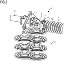
- FIGS. 1 and 2 show an inventive arrangement 1 in the mounting position.
- a boom 11 is attached to a grounding point 3.
- an insulator 5 hangs here from two parallel insulator chains.
- a holding device 4 is arranged, in which an overhead line 2 is held.
- two electrically connected to the overhead line 2 high voltage electrodes 9 are arranged.
- a fastening device 6 is fixed to which in turn a line arrester 7 is attached.
- the line arrester 7 is here aligned in the plane defined by the insulator 5 and the overhead line 2 level. But it is also possible an orientation perpendicular to this plane.
- the line arrester 7 has a cylindrical insulated housing, in the interior of which discharge elements are located. At the ends of the housing, an end fitting 17 is arranged in each case. One of the end fittings 17 is fastened with mounting screws 32 to the fastening device 6, at the other end a spark electrode 8 is arranged.
- the spark electrode 8 forms with the overhead line 2, or as here with the high voltage electrode 9, a spark gap 10 from.
- the line arrester 7 is in the mounting position.
- the spark gap 10 so the smallest distance between the spark electrode 8 and a high voltage leading part of the assembly 1, in this case the high voltage electrode 9, here is so large that the voltages occurring in normal operation of the overhead line 2 are not sufficient to over the spark gap 10 to form an arc.
- this mounting position is safe, so that a mounting of the line arrester 7 can be done in high-voltage overhead line 2, without the assembly staff running the risk of coming into contact with high-voltage parts.
- the line arrester 7 is mounted for mounting on the arm 11 to the fastening device 6 by means of screws 32 and locked at an angle ⁇ of here 90 ° between the Kirsableiterlijnsachse 15 and the insulator longitudinal axis 16 through the locking pin 25. During assembly of the fastening device 6 at the grounding point 3 of the arm 11 of the line arrester 7 remains in this position.
- angles ⁇ may not be fallen below. This depends essentially on the length ratio of Kirsableiter 7 and insulator 5 and the voltage applied to the overhead line 2 high voltage. In practice, angles ⁇ between 70 ° and 120 ° prove to be advantageous. At angles ⁇ greater than 90 °, however, it should be noted that with possibly arranged above the overhead line 2 further overhead lines, a spark gap is formed, which can lead to the rollover. Therefore, an angle ⁇ of about 90 ° proves to be particularly advantageous.
- the Figures 3 and 4 show an inventive arrangement 1 in the working position.
- the line arrester 7 is in this case pivoted with respect to the mounting position about a horizontal axis of rotation 12 downwards towards the overhead line 2.
- the angle ⁇ is here about 50 °.
- the spark gap 10 is now dimensioned so that when overvoltages occur in the overhead line 2, a sparkover between the high voltage electrode 9 and the spark electrode 8 occurs, whereby the intermediate air is ionized and thus conductive.
- the overvoltage is now discharged via the line arrester 7 to the grounding point 3. After the decay of the overvoltage extinguishes the arc and the line arrester 7 is again isolated from the overhead line 2.
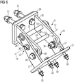
- the FIG. 5 shows an embodiment of a fastening device 6 in the mounting position, the FIG. 6 in the working position.
- the fastening device 6 has a fastening plate 20 for attachment to the grounding point 3 by means of the screws 31.
- it has a mounting plate 21 for fastening the Kirsableiters by means of screws 32.
- Mounting plate 20 and mounting plate 21 are connected to each other via a hinge 22 so that they can be rotated about a parallel to both extending, horizontal axis of rotation 12 against each other.
- the rotary joint 22 has two parallel and connected to the mounting plate 20 first leg 26, and two equally parallel and connected to the mounting plate 21 second leg 27.
- the legs 26, 27 are perpendicular from the mounting plate 20 and the mounting plate 21 from.
- the legs 26, 27 each have at their center an axle hole 34, wherein the legs 26, 27 are arranged so that their axial holes lie along the axis of rotation 12. Through the axle holes 34, a pivot pin 24 through all four legs 26, 27 is inserted, which forms the axis of rotation 12. This is still secured with locking pins 30.
- the legs 27 each have a not visible in the figures locking hole 33 through which a locking pin 25 is pluggable.
- the legs 26 each have two such locking holes 33 at the same distance from the axis of rotation 12.
- the locking pin 25 can thus be guided by the locking holes 33 in the legs 27 and by a respective locking hole 33 in each of the legs 26, so that the rotary joint 22 can be locked in two positions.
- the locking pin 25 is then secured by means of the locking pin 30.
- the in the FIG. 5 shown position corresponds to the mounting position in the FIG. 6 the working position.
- the rotary joint may have a rotation angle limiter 23. In the illustrated embodiment, this is introduced by two introduced into the legs 26 circular segment-shaped Slotted holes 29 and two attached to the legs 27 and inserted through the slots 29 fixing screws 35 achieved.
- the line arrester 7 For mounting the line arrester 7, this is first attached to the mounting plate 21 of the fastening device 6 with an end fitting 17 by means of the screws 32. This can already be done in the production plant of the line arrester 7 or at the place of assembly, for example, at the foot of the mast to which the line arrester 7 is to be mounted.
- the fastening device 6 is now brought into the mounting position and secured there by means of the locking pin 25.
- the screws 35 are tightened so that the legs 26 and 27 are pressed in pairs against each other. Later, when the line arrester 7 is attached to the mast, the torque acting by the weight of the line arrester 7 is thus absorbed, so that the arresting pin 25 can be easily removed again. In addition, the position of the Kirsableiters 7 is thereby double locked.
- the attached to the fastening device 6 line arrester 7 is now raised to the grounding point 3. This can be done by means of a grounded lifting device, a pulley or a helicopter. Preferably, the lifting is carried out so that the Kirsableiterlssensachse 15 is aligned horizontally.
- the mounting plate 20 is now attached to the grounding point 3 by means of screws 31 by a fitter. Meanwhile, the free end of the Kirsableiters 7 can be held with the spark electrode 8 by another fitter or by ropes. Is the line arrester 7 attached to the grounding point 3, the axle pin 24 can be pulled out. By the weight of the Kirsableiters 7 this is pivoted down to the overhead line 2 in the working position. If necessary, the screws 35 must first be loosened.
- the pivoting into the working position takes place without further intervention of a technician, so that they are not endangered.
- the rotation angle limiter 23 ensures that the line arrester 7 does not pivot down further than to the working position.
- the locking pin 25 can now back in the locking holes 33 are inserted, so that the line arrester 7 is now locked in the working position.
Landscapes
- Suspension Of Electric Lines Or Cables (AREA)
- Insulators (AREA)
Description
- Leitungsableiter sind in einem Stromübertragungsnetz, insbesondere in Hochspannungsnetzen mit Spannungen über 1 kV, parallel zu einem Leitungsisolator der Freileitung angeschlossen. Sie beinhalten ein Ableitelement aus nichtlinearen Metalloxidwiderständen in einem Porzellan oder Kunststoffgehäuse. Leitungsableiter werden vorzugsweise dort eingesetzt, wo es auf Grund fehlendem oder ungenügendem Erdseilschutz und/oder hoher Masterdungsstoßwiderstände (z.B. bei stark felsigem Untergrund) gehäuft zu rückwärtigen Überschlägen kommt. Zur nachträglichen Erhöhung der Versorgungszuverlässigkeit bereits bestehender Übertragungs- oder Verteilungsleitungen ist oft die Installation von Leitungsableitern an allen oder auch nur an einigen Masten eine kostengünstige Alternative zur Verbesserung des Erdseilschutzes oder der Masterdungsverhältnisse. Leitungsableiter werden sowohl in funkenstreckenloser Technik eingesetzt als auch in Verbindung mit einer externen Serienfunkenstrecke, die die Ableiter im Normalbetrieb, gegenüber Schaltüberspannungen oder auch nach einer Überlastung von der Leitung isolieren. Im nachfolgenden werden nur Leitungsableiter mit externer Serienfunkenstrecke betrachtet.
- Ein Leitungsableiter mit externer Serienfunkenstrecke (englisch: externally gapped line arrester oder EGLA) weist eine in Serie zu dem Ableitelement geschaltete Funkenstrecke auf. Ein Ende des Leitungsableiters ist an einem Erdungspunkt des Freileitungsmastes geerdet, am anderen Ende befindet sich eine Funkenelektrode, die mit einem Funkenhorn am hochspannungsseitigen Ende des Leitungsisolators eine Funkenstrecke bildet. Statt dem Funkenhorn kann auch die Freileitung selber als hochspannungsseitiges Ende der Funkenstrecke dienen.
- Tritt eine Überspannung beispielsweise durch einen Blitzeinschlag in die Freileitung auf, so wird die Funkenstrecke durch einen Lichtbogen kurzgeschlossen und die Überspannung kontrolliert durch den Leitungsableiter zur Erde hin abgeleitet. Nach dem Abklingen der Überspannung erlischt die Funkenstrecke und isoliert den Leitungsableiter von der Hochspannung. Leitungsableiter mit externer Serienfunkenstrecke sind in der IEC 60099-8 genormt. In der
US 2012/0087055 A1 ist ein solcher Leitungsableiter mit externer Serienfunkenstrecke gezeigt. - Häufig werden Leitungsableiter mit externer Serienfunkenstrecke in bestehende Hochspannungsnetze nachgerüstet. Da ein Leitungsableiter mit Funkenelektrode mehrere Meter lang sein kann, besteht die Gefahr, dass beim Hantieren die Funkenelektrode zu nahe an die Freileitung kommt und dadurch ein Überschlag ausgelöst wird, wodurch das Montagepersonal der Gefahr eines Stromschlags ausgesetzt ist. Deswegen war es bislang nötig, den entsprechenden Netzabschnitt abzuschalten, um eine Gefährdung des Montagepersonals durch die Hochspannung zu vermeiden.
- Eine gattungsgemäße Anordnung gemäss dem Oberbegriff des Anspruchs 1 ist aus der Druckschrift
JP 2003 217790 A - Aufgabe der vorliegenden Erfindung ist es, eine Anordnung zur Befestigung einer Freileitung an einem Mast anzugeben, mittels der ein Leitungsableiter mit externer Serienfunkenstrecke auch bei an der Freileitung anliegender Hochspannung montiert werden kann.
- Die Lösung der Aufgabe erfolgt durch eine Anordnung mit den Merkmalen des Anspruchs 1 -.
- Erfindungsgemäß weist eine Anordnung zur Befestigung einer Freileitung an einem Mast einen zwischen einem Erdungspunkt am Mast und einer Haltevorrichtung für die Freileitung angeordneten Isolator und einen am Erdungspunkt mittels einer Befestigungsvorrichtung befestigten Leitungsableiter auf. Der Leitungsableiter weist eine Funkenelektrode auf, die von der Freileitung oder einer mit der Freileitung verbundenen Hochspannungselektrode beabstandet ist. Der Abstand zwischen der Funkenelektrode und der Freileitung oder der Hochspannungselektrode definiert eine Funkenstrecke, in der bei geeignetem Abstand eine an der Freileitung anliegende Überspannung einen Lichtbogen zündet, der eine leitende Verbindung zwischen dem Erdungspunkt und der Freileitung über den Leitungsableiter herstellt, so dass die Überspannung zur Erde hin abfließen kann. Der Leitungsableiter und die Funkenstrecke sind in Reihe zueinander und parallel zum Isolator geschaltet. Der Leitungsableiter ist damit ein Leitungsableiter mit externer Serienfunkenstrecke. Der Leitungsableiter ist derart mittels der Befestigungsvorrichtung am Erdungspunkt angelenkt, dass der Leitungsableiter zwischen einer sicheren Montageposition und einer Arbeitsposition schwenkbar und in der Montageposition arretierbar ist. Dabei ist die Funkenstrecke in der Montageposition größer, als in der Arbeitsposition. Durch die Arretierung des Leitungsableiters in der Montageposition ist somit sichergestellt, dass die Funkenelektrode während der Montage einen größeren Abstand von einem Hochspannung führenden Teil der Anordnung hat, als in der Arbeitsposition, die der Leitungsableiter im normalen Betrieb der Anordnung einnimmt. Somit ist eine Montage des Leitungsableiters auch bei Hochspannung führender Freileitung möglich.
- Ein Winkel α zwischen einer Isolatorlängsachse und einer Leitungsableiterlängsachse in der Montageposition mehr als 70° und in der Arbeitsposition weniger als 60°. Die durch den Leitungsableiter und den Isolator aufgespannte Ebene kann dabei in der durch den Isolator und die Freileitung aufgespannten Ebene liegen oder auch in einem Winkel β dazu ausgerichtet sein. In letzterem Fall bildet der Isolator die Schnittlinie der beiden Ebenen. Der Winkel β kann außerdem in der Montageposition anders sein, als in der Arbeitsposition. Vorzugsweise beträgt er in der Montageposition 90°. Der in der Montageposition größere Winkel α stellt sicher, dass die Funkenstrecke während der Montage ausreichend groß ist, so dass trotz anliegender Hochspannung an der Freileitung kein Lichtbogen zünden kann.
- Die Befestigungsvorrichtung weist eine Befestigungsplatte zur Befestigung am Erdungspunkt und eine Montageplatte zur Befestigung des Leitungsableiters auf. Befestigungsplatte und Montageplatte sind über ein Drehgelenk miteinander verbunden.
- Das Drehgelenk ist zwischen einer ersten Winkelposition und einer zweiten Winkelposition drehbar ist, wobei der Leitungsableiter in der ersten Winkelposition in der Montageposition und in der zweiten Winkelposition in der Arbeitsposition angeordnet.
- Ein solches Drehgelenk erlaubt auf einfache Weise ein Drehen oder Schwenken des Leitungsableiters von der Montageposition in die Arbeitsposition.
- Es wird auch bevorzugt, dass das Drehgelenk eine Drehwinkelbegrenzung aufweist, die nur Drehwinkel zwischen der ersten und der zweiten Winkelposition zulässt. Somit kann verhindert werden, dass versehentlich Winkel eingestellt werden, die kleiner sind, als in der Arbeitsposition, wodurch ein Lichtbogen gezündet werden könnte.
- Für Verfahren zur Montage eines Leitungsableiters mit externer Serienfunkenstrecke an einem Erdungspunkt eines Freileitungsmastes wird davon ausgegangen, dass eine Freileitung an einem Isolator an einem Mast befestigt und in Betrieb genommen ist. Ein Leitungsableiter mit externer Serienfunkenstrecke soll nachgerüstet werden. Zunächst wird der Leitungsableiter an der Befestigungsvorrichtung befestigt. Dies kann bereits im Werk nach der Herstellung des Leitungsableiters erfolgen, oder auch erst am Ort der Montage beispielsweise auf einem Fahrzeug oder am Mastfuß. Dann wird die Befestigungsvorrichtung in einer sicheren Montageposition arretiert. Danach wird der Leitungsableiter mit der Befestigungsvorrichtung zum Erdungspunkt angehoben. Dies kann beispielsweise mittels Seilzügen, einem geerdeten Hubwagen oder per Hubschrauber erfolgen. Nun wird die Befestigungsvorrichtung am Erdungspunkt angebracht und dort befestigt. Währenddessen wird der Leitungsableiter durch die arretierte Befestigungsvorrichtung in der sicheren Montageposition gehalten, so dass keine Gefährdung des Montagepersonals erfolgt. Die Arretierung der Befestigungsvorrichtung in der Montageposition wird nun gelöst und der Leitungsableiter um eine Drehachse in die Arbeitsposition geschwenkt. Die Drehachse ist dabei bevorzugt horizontal ausgerichtet. Optional kann die Befestigungsvorrichtung nun noch in der Arbeitsposition des Leitungsableiters arretiert werden. Ein solches Verfahren erlaubt eine Montage eines Leitungsableiters bei an der Freileitung anliegender Hochspannung auf besonders einfache und sichere Weise.
- Im Folgenden wird die Erfindung anhand der Zeichnungen näher erläutert. Dabei zeigen:
- Figur 1
- eine erfindungsgemäße Anordnung in der Montageposition,
- Figur 2
- eine Detailansicht der
Figur 1 , - Figur 3
- eine erfindungsgemäße Anordnung in der Arbeitsposition,
- Figur 4
- eine Detailansicht der
Figur 3 , - Figur 5
- eine Befestigungsvorrichtung in der Montageposition,
- Figur 6
- eine Befestigungsvorrichtung in der Arbeitsposition.
- Einander entsprechende Teile sind in allen Figuren mit den gleichen Bezugszeichen versehen.
- Die
Figuren 1 und2 zeigen eine erfindungsgemäße Anordnung 1 in der Montageposition. An einem hier nicht dargestellten Mast für eine Freileitung 2 ist ein Ausleger 11 mit einem Erdungspunkt 3 befestigt. An dem Ausleger 11 hängt ein Isolator 5 hier aus zwei parallelen Isolatorketten. Am gegenüberliegenden Ende des Isolators 5 ist eine Haltevorrichtung 4 angeordnet, in der eine Freileitung 2 gehalten wird. Ebenfalls am unteren Ende des Isolators 5 sind zwei mit der Freileitung 2 elektrisch verbundene Hochspannungselektroden 9 angeordnet. Am Erdungspunkt 3 ist eine Befestigungsvorrichtung 6 befestigt, an der wiederum ein Leitungsableiter 7 befestigt ist. Der Leitungsableiter 7 ist hier aus in der durch den Isolator 5 und die Freileitung 2 aufgespannten Ebene ausgerichtet. Möglich ist aber auch eine Ausrichtung senkrecht zu dieser Ebene. - Der Leitungsableiter 7 weist ein zylindrisches isoliertes Gehäuse auf, in dessen Inneren sich Ableitelemente befinden. An den Enden des Gehäuses ist jeweils eine Endarmatur 17 angeordnet. Eine der Endarmaturen 17 ist mit Montageschrauben 32 an der Befestigungsvorrichtung 6 befestigt, am anderen Ende ist eine Funkenelektrode 8 angeordnet. Die Funkenelektrode 8 bildet mit der Freileitung 2, oder wie hier mit der Hochspannungselektrode 9 eine Funkenstrecke 10 aus. In diesem Fall ist der Leitungsableiter 7 in der Montageposition. Die Funkenstrecke 10, also der kleinste Abstand zwischen der Funkenelektrode 8 und einem Hochspannung führenden Teil der Anordnung 1, in diesem Fall der Hochspannungselektrode 9, ist hier so groß, dass die im normalen Betrieb der Freileitung 2 auftretenden Spannungen nicht ausreichen, um über die Funkenstrecke 10 einen Lichtbogen auszubilden. Somit ist diese Montageposition sicher, so dass eine Montage des Leitungsableiters 7 bei unter Hochspannung stehender Freileitung 2 erfolgen kann, ohne dass das Montagepersonal Gefahr läuft, in Kontakt mit Hochspannung führenden Teilen zu kommen. Der Leitungsableiter 7 ist zur Montage am Ausleger 11 an der Befestigungsvorrichtung 6 mittels der Schrauben 32 befestigt und im Winkel α von hier 90° zwischen der Leitungsableiterlängsachse 15 und der Isolatorlängsachse 16 durch den Arretierungsbolzen 25 arretiert. Während der Montage der Befestigungsvorrichtung 6 am Erdungspunkt 3 des Auslegers 11 verbleibt der Leitungsableiter 7 in dieser Position.
- In der Montageposition darf ein bestimmter Winkel α nicht unterschritten werden. Dieser hängt im Wesentlichen vom Längenverhältnis von Leitungsableiter 7 und Isolator 5 und der an der Freileitung 2 anliegenden Hochspannung ab. Praktisch erweisen sich Winkel α zwischen 70° und 120° als vorteilhaft. Bei Winkeln α größer als 90° ist allerdings zu beachten, dass mit möglicherweise oberhalb der Freileitung 2 angeordneten weiteren Freileitungen eine Funkenstrecke ausgebildet wird, die zum Überschlag führen kann. Deswegen erweist sich ein Winkel α von etwa 90° als besonders vorteilhaft.
- Die
Figuren 3 und4 zeigen eine erfindungsgemäße Anordnung 1 in der Arbeitsposition. Der Leitungsableiter 7 ist hierbei gegenüber der Montageposition um eine horizontale Drehachse 12 nach unten Richtung Freileitung 2 geschwenkt. Der Winkel α beträgt hier etwa 50°. Die Funkenstrecke 10 ist nun so bemessen, dass bei auftretenden Überspannungen in der Freileitung 2 ein Funkenüberschlag zwischen der Hochspannungselektrode 9 und der Funkenelektrode 8 auftritt, wodurch die dazwischenliegende Luft ionisiert und somit leitend wird. Die Überspannung wird nun über den Leitungsableiter 7 zum Erdungspunkt 3 abgeleitet. Nach dem Abklingen der Überspannung erlischt der Lichtbogen und der Leitungsableiter 7 ist wieder von der Freileitung 2 isoliert. - Die
Figur 5 zeigt ein Ausführungsbeispiel einer Befestigungsvorrichtung 6 in der Montageposition, dieFigur 6 in der Arbeitsposition. Die Befestigungsvorrichtung 6 weist eine Befestigungsplatte 20 zur Befestigung am Erdungspunkt 3 mittels der Schrauben 31 auf. Außerdem weist sie eine Montageplatte 21 zur Befestigung des Leitungsableiters mittels der Schrauben 32 auf. Befestigungsplatte 20 und Montageplatte 21 sind über ein Drehgelenk 22 miteinander verbunden, so dass sie um eine parallel zu beiden verlaufende, horizontale Drehachse 12 gegeneinander verdreht werden können. Das Drehgelenk 22 weist dabei zwei parallel verlaufende und mit der Befestigungsplatte 20 verbundene erste Schenkel 26, und zwei ebenso parallel verlaufende und mit der Montageplatte 21 verbundene zweite Schenkel 27 auf. Die Schenkel 26, 27 stehen dabei senkrecht von der Befestigungsplatte 20 beziehungsweise der Montageplatte 21 ab. Die Schenkel 26, 27 weisen in ihrer Mitte jeweils ein Achsloch 34 auf, wobei die Schenkel 26, 27 so angeordnet sind, dass ihre Achslöcher entlang der Drehachse 12 liegen. Durch die Achslöcher 34 ist ein Achsbolzen 24 durch alle vier Schenkel 26, 27 gesteckt, der die Drehachse 12 bildet. Dieser ist noch mit Sicherungsstiften 30 gesichert. - In einem Abstand von der Drehachse 12 weisen die Schenkel 27 jeweils ein in den Figuren nicht sichtbares Arretierungsloch 33 auf, durch das ein Arretierungsbolzen 25 steckbar ist. Die Schenkel 26 weisen jeweils zwei solcher Arretierungslöcher 33 mit demselben Abstand von der Drehachse 12 auf.
- Der Arretierungsbolzen 25 kann so durch die Arretierungslöcher 33 in den Schenkeln 27 und durch jeweils ein Arretierungsloch 33 in jedem der Schenkel 26 geführt werden, so dass das Drehgelenk 22 in zwei Positionen arretierbar ist. Der Arretierungsbolzen 25 wird dann mittels des Sicherungsstifts 30 gesichert. Die in der
Figur 5 gezeigte Position entspricht dabei der Montageposition, die in derFigur 6 der Arbeitsposition. - Zusätzlich kann das Drehgelenk eine Drehwinkelbegrenzung 23 aufweisen. In der dargestellten Ausführungsform wird diese durch zwei in den Schenkeln 26 eingebrachte kreissegmentförmige Langlöcher 29 und zwei an den Schenkeln 27 angebrachte und durch die Langlöcher 29 gesteckte Fixierungsschrauben 35 erzielt.
- Zur Montage des Leitungsableiters 7 wird dieser zunächst mit einer Endarmatur 17 mittels der Schrauben 32 an der Montageplatte 21 der Befestigungsvorrichtung 6 angebracht. Dies kann bereits im Herstellungswerk des Leitungsableiters 7 oder am Ort der Montage beispielsweise am Fuß des Mastes, an dem der Leitungsableiter 7 montiert werden soll, erfolgen. Die Befestigungsvorrichtung 6 wird nun in die Montageposition gebracht und dort mittels des Arretierungsbolzens 25 gesichert. Die Schrauben 35 werden angezogen, so dass die Schenkel 26 und 27 paarweise gegeneinander gepresst werden. Wenn später der Leitungsableiter 7 am Mast befestigt wird, wird so das durch das Gewicht des Leitungsableiters 7 wirkende Drehmoment aufgenommen, so dass der Arretierungsbolzen 25 leicht wieder entfernt werden kann. Außerdem ist die Position des Leitungsableiters 7 dadurch doppelt arretiert. Der an der Befestigungsvorrichtung 6 angebrachte Leitungsableiter 7 wird nun zum Erdungspunkt 3 angehoben. Dies kann mittels einer geerdeten Hubvorrichtung, einem Flaschenzug oder auch einem Hubschrauber erfolgen. Vorzugsweise erfolgt bereits das Anheben so, dass die Leitungsableiterlängsachse 15 horizontal ausgerichtet ist. Die Befestigungsplatte 20 wird nun am Erdungspunkt 3 mittels der Schrauben 31 durch einen Monteur befestigt. Währenddessen kann das freie Ende des Leitungsableiters 7 mit der Funkenelektrode 8 durch einen weiteren Monteur oder durch Seile gehalten werden. Ist der Leitungsableiter 7 am Erdungspunkt 3 befestigt, kann der Achsbolzen 24 herausgezogen werden. Durch das Gewicht des Leitungsableiters 7 wird dieser nach unten zur Freileitung 2 in die Arbeitsposition geschwenkt. Gegebenenfalls müssen dazu die Schrauben 35 zuvor gelockert werden. Das Schwenken in die Arbeitsposition erfolgt ohne weiteren Eingriff eines Monteurs, so dass diese nicht gefährdet werden. Die Drehwinkelbegrenzung 23 gewährleistet, dass der Leitungsableiter 7 nicht weiter nach unten schwenkt, als bis zur Arbeitsposition. Der Arretierungsbolzen 25 kann nun wieder in die Arretierungslöcher 33 eingesteckt werden, so dass der Leitungsableiter 7 nun in der Arbeitsposition arretiert ist.
Claims (2)
- Anordnung (1) zur Befestigung einer Freileitung (2) an einem Mast, mit- einem zwischen einem Erdungspunkt (3) am Mast und einer Haltevorrichtung (4) für die Freileitung (2) angeordneten Isolator (5),- einem am Erdungspunkt (3) mittels einer Befestigungsvorrichtung (6) befestigten Leitungsableiter (7) mit einer Funkenelektrode (8), die von der Freileitung (2) oder einer mit dieser verbundenen Hochspannungselektrode (9) beabstandet ist und der Abstand eine Funkenstrecke (10) definiert, wobei- der Leitungsableiter (7) und die Funkenstrecke (10) in Reihe zueinander und parallel zum Isolator (5) geschaltet sind, wobei der Leitungsableiter (7) derart mittels der Befestigungsvorrichtung (6) am Erdungspunkt (3) angelenkt ist, dass der Leitungsableiter (7) zwischen einer sicheren Montageposition und einer Arbeitsposition schwenkbar und in der Montageposition arretierbar ist, wobei- die Funkenstrecke (10) in der Montageposition größer ist, als in der Arbeitsposition und wobei- die Befestigungsvorrichtung (6) eine Befestigungsplatte (20) zur Befestigung am Erdungspunkt (3) und eine Montageplatte (21) zur Befestigung des Leitungsableiters (7) aufweist, die über ein Drehgelenk (22) miteinander verbunden sind, und wobeidas Drehgelenk (22) zwischen einer ersten Winkelposition und einer zweiten Winkelposition drehbar ist, wobei der Leitungsableiter (7) in der ersten Winkelposition in der Montageposition und in der zweiten Winkelposition in der Arbeitsposition angeordnet ist,
dadurch gekennzeichnet,
dass das Drehgelenk (22) zwei parallel verlaufende und mit der Befestigungsplatte (20) verbundene erste Schenkel (26), und zwei ebenso parallel verlaufende und mit der Montageplatte (21) verbundene zweite Schenkel (27) aufweist, wobei
die Schenkel (26, 27) jeweils ein Achsloch (34) aufweisen und so angeordnet sind, dass ihre Achslöcher (34) entlang einer Drehachse (12) des Drehgelenkes (22) liegen und wobei durch die Achslöcher (34) ein Achsbolzen (24) durch alle vier Schenkel (26, 27) gesteckt ist, der die Drehachse (12) bildet, und wobei
ein Winkel (α) zwischen einer Isolatorlängsachse (16) und einer Leitungsableiterlängsachse (15) in der Montageposition mehr als 70° und in der Arbeitsposition weniger als 60° beträgt. - Anordnung (1) nach Anspruch1 1,
dadurch gekennzeichnet,
dass das Drehgelenk (22) eine Drehwinkelbegrenzung (23) aufweist, die nur Drehwinkel zwischen der ersten und der zweiten Winkelposition zulässt.
Priority Applications (5)
| Application Number | Priority Date | Filing Date | Title |
|---|---|---|---|
| EP13185972.0A EP2854242B1 (de) | 2013-09-25 | 2013-09-25 | Anordnung zur Befestigung einer Freileitung an einem Mast |
| PCT/EP2014/069286 WO2015043952A1 (de) | 2013-09-25 | 2014-09-10 | Anordnung zur befestigung einer freileitung an einem mast und verfahren zur montage eines leitungsableiters |
| MYPI2016701021A MY184708A (en) | 2013-09-25 | 2014-09-10 | Arrangement for fastening an overhead line to a mast and method for mounting a line arrester |
| BR112016006036A BR112016006036B8 (pt) | 2013-09-25 | 2014-09-10 | Dispositivo de fixação de uma linha elétrica aérea a um mastro |
| CN201480052057.4A CN105580224B (zh) | 2013-09-25 | 2014-09-10 | 用于将架空线固定在塔杆上的装置和用于安装线路避雷器的方法 |
Applications Claiming Priority (1)
| Application Number | Priority Date | Filing Date | Title |
|---|---|---|---|
| EP13185972.0A EP2854242B1 (de) | 2013-09-25 | 2013-09-25 | Anordnung zur Befestigung einer Freileitung an einem Mast |
Publications (2)
| Publication Number | Publication Date |
|---|---|
| EP2854242A1 EP2854242A1 (de) | 2015-04-01 |
| EP2854242B1 true EP2854242B1 (de) | 2019-10-30 |
Family
ID=49293462
Family Applications (1)
| Application Number | Title | Priority Date | Filing Date |
|---|---|---|---|
| EP13185972.0A Active EP2854242B1 (de) | 2013-09-25 | 2013-09-25 | Anordnung zur Befestigung einer Freileitung an einem Mast |
Country Status (5)
| Country | Link |
|---|---|
| EP (1) | EP2854242B1 (de) |
| CN (1) | CN105580224B (de) |
| BR (1) | BR112016006036B8 (de) |
| MY (1) | MY184708A (de) |
| WO (1) | WO2015043952A1 (de) |
Families Citing this family (4)
| Publication number | Priority date | Publication date | Assignee | Title |
|---|---|---|---|---|
| CA3110844A1 (en) * | 2018-08-21 | 2020-02-27 | Siemens Energy Global GmbH & Co. KG | Insulator having an end fitting and a connecting device as well as arrangement for dissipating overvoltage |
| CN110535089A (zh) * | 2019-10-11 | 2019-12-03 | 云南电网有限责任公司电力科学研究院 | 配电网避雷线间接接地的敷设方法及装置 |
| DE102020202407A1 (de) | 2020-02-25 | 2021-08-26 | Siemens Energy Global GmbH & Co. KG | Montagevorrichtung und Verfahren zur Montage eines Leitungsableiters an einem Leitungsmast |
| CN113922319A (zh) * | 2021-09-26 | 2022-01-11 | 西门子避雷器(无锡)有限公司 | 线路避雷器的安装组件及线路避雷器 |
Family Cites Families (3)
| Publication number | Priority date | Publication date | Assignee | Title |
|---|---|---|---|---|
| FR2770345B1 (fr) * | 1997-10-24 | 1999-12-03 | Sediver | Montage de parafoudre pour ligne electrique aerienne avec indicateur de fonctionnement du parafoudre |
| JP2003217790A (ja) * | 2002-01-17 | 2003-07-31 | Asahi Tec Corp | 避雷装置 |
| US8711538B2 (en) | 2010-10-06 | 2014-04-29 | Jonathan Jay Woodworth | Externally gapped line arrester |
-
2013
- 2013-09-25 EP EP13185972.0A patent/EP2854242B1/de active Active
-
2014
- 2014-09-10 WO PCT/EP2014/069286 patent/WO2015043952A1/de active Application Filing
- 2014-09-10 CN CN201480052057.4A patent/CN105580224B/zh active Active
- 2014-09-10 MY MYPI2016701021A patent/MY184708A/en unknown
- 2014-09-10 BR BR112016006036A patent/BR112016006036B8/pt active IP Right Grant
Non-Patent Citations (1)
| Title |
|---|
| None * |
Also Published As
| Publication number | Publication date |
|---|---|
| BR112016006036B1 (pt) | 2021-11-30 |
| CN105580224B (zh) | 2017-10-10 |
| BR112016006036A2 (pt) | 2017-08-01 |
| CN105580224A (zh) | 2016-05-11 |
| WO2015043952A1 (de) | 2015-04-02 |
| EP2854242A1 (de) | 2015-04-01 |
| BR112016006036B8 (pt) | 2023-04-25 |
| MY184708A (en) | 2021-04-19 |
Similar Documents
| Publication | Publication Date | Title |
|---|---|---|
| EP0396936B1 (de) | Einrichtung zum Schutz elektrischer Anlagen | |
| DE102006052955B4 (de) | Überspannungsableiter mit einem Gehäuse und mit mindestens einem Ableitelement | |
| EP2949019B1 (de) | Messsystem zur dauerüberwachung einer hochspannungsdurchführung | |
| EP2842138B1 (de) | Vorrichtung zum ableiten einer elektrischen überspannung | |
| WO2016150709A1 (de) | Isolatoranordnung für eine freileitung | |
| EP2854242B1 (de) | Anordnung zur Befestigung einer Freileitung an einem Mast | |
| EP0387865B1 (de) | Funkenschutzeinrichtung für isolierte Leitungen, insbesondere Freileitungen | |
| DE69833634T2 (de) | Blitzableitervorrichtung für elektrische Freileitung mit einem Fehlerindikator | |
| DE102012024352B4 (de) | Überspannungsschutzgerät | |
| EP4439091A1 (de) | Zählersteckklemme, baugruppe und schaltschrank | |
| EP3002840B1 (de) | Befestigungsvorrichtung für einen isolator | |
| EP3552219B1 (de) | Hochspannungsisolator mit lichtbogenschutzring | |
| EP2366286B1 (de) | Isolierende Vogelschutzabdeckung | |
| EP2991084B1 (de) | Überspannungsableiter | |
| EP3579253B1 (de) | Kettenanordnung für eine hoch- oder höchstspannungs-freileitung | |
| DE102012217789A1 (de) | Einrichtung zur gasdichten Durchführung eines Leiters durch eine Gehäusewand | |
| EP3164919B1 (de) | Kabelendverschluss zur anbindung einer schaltanlage an ein hochspannungskabel | |
| DE202014003281U1 (de) | Bausatz für Kabelendverschlüsse zur Anbindung einer Schaltanlage an ein Hochspannungskabel | |
| EP2871484B1 (de) | Koppler, Kopplermodul und Kopplersystem zum Anschluss von Mess- und/oder Kommunikationsmitteln an ein Energieversorgungsnetzwerk | |
| DE102012106505A1 (de) | Freischalteinrichtung für einen eine Gleichspannung erzeugenden Photovoltaik-Strang | |
| DE102011088353A1 (de) | Stützisolatoranordnung | |
| DE2348137A1 (de) | Elektrische hochspannungseinrichtung mit einer metallkapselung und einem ueberspannungsableiter | |
| CH645483A5 (de) | Vorrichtung zur ueberspannungsableitung. | |
| EP3133613A1 (de) | Koronaring | |
| DE10324342B4 (de) | Schutzabdeckung |
Legal Events
| Date | Code | Title | Description |
|---|---|---|---|
| PUAI | Public reference made under article 153(3) epc to a published international application that has entered the european phase |
Free format text: ORIGINAL CODE: 0009012 |
|
| 17P | Request for examination filed |
Effective date: 20130925 |
|
| AK | Designated contracting states |
Kind code of ref document: A1 Designated state(s): AL AT BE BG CH CY CZ DE DK EE ES FI FR GB GR HR HU IE IS IT LI LT LU LV MC MK MT NL NO PL PT RO RS SE SI SK SM TR |
|
| AX | Request for extension of the european patent |
Extension state: BA ME |
|
| R17P | Request for examination filed (corrected) |
Effective date: 20150928 |
|
| RBV | Designated contracting states (corrected) |
Designated state(s): AL AT BE BG CH CY CZ DE DK EE ES FI FR GB GR HR HU IE IS IT LI LT LU LV MC MK MT NL NO PL PT RO RS SE SI SK SM TR |
|
| RAP1 | Party data changed (applicant data changed or rights of an application transferred) |
Owner name: SIEMENS AKTIENGESELLSCHAFT |
|
| STAA | Information on the status of an ep patent application or granted ep patent |
Free format text: STATUS: EXAMINATION IS IN PROGRESS |
|
| 17Q | First examination report despatched |
Effective date: 20180620 |
|
| GRAP | Despatch of communication of intention to grant a patent |
Free format text: ORIGINAL CODE: EPIDOSNIGR1 |
|
| STAA | Information on the status of an ep patent application or granted ep patent |
Free format text: STATUS: GRANT OF PATENT IS INTENDED |
|
| INTG | Intention to grant announced |
Effective date: 20190528 |
|
| GRAS | Grant fee paid |
Free format text: ORIGINAL CODE: EPIDOSNIGR3 |
|
| GRAA | (expected) grant |
Free format text: ORIGINAL CODE: 0009210 |
|
| STAA | Information on the status of an ep patent application or granted ep patent |
Free format text: STATUS: THE PATENT HAS BEEN GRANTED |
|
| AK | Designated contracting states |
Kind code of ref document: B1 Designated state(s): AL AT BE BG CH CY CZ DE DK EE ES FI FR GB GR HR HU IE IS IT LI LT LU LV MC MK MT NL NO PL PT RO RS SE SI SK SM TR |
|
| REG | Reference to a national code |
Ref country code: GB Ref legal event code: FG4D Free format text: NOT ENGLISH |
|
| REG | Reference to a national code |
Ref country code: CH Ref legal event code: EP |
|
| REG | Reference to a national code |
Ref country code: AT Ref legal event code: REF Ref document number: 1197162 Country of ref document: AT Kind code of ref document: T Effective date: 20191115 |
|
| REG | Reference to a national code |
Ref country code: DE Ref legal event code: R096 Ref document number: 502013013822 Country of ref document: DE |
|
| REG | Reference to a national code |
Ref country code: IE Ref legal event code: FG4D Free format text: LANGUAGE OF EP DOCUMENT: GERMAN |
|
| REG | Reference to a national code |
Ref country code: SE Ref legal event code: TRGR |
|
| REG | Reference to a national code |
Ref country code: LT Ref legal event code: MG4D |
|
| PG25 | Lapsed in a contracting state [announced via postgrant information from national office to epo] |
Ref country code: FI Free format text: LAPSE BECAUSE OF FAILURE TO SUBMIT A TRANSLATION OF THE DESCRIPTION OR TO PAY THE FEE WITHIN THE PRESCRIBED TIME-LIMIT Effective date: 20191030 Ref country code: BG Free format text: LAPSE BECAUSE OF FAILURE TO SUBMIT A TRANSLATION OF THE DESCRIPTION OR TO PAY THE FEE WITHIN THE PRESCRIBED TIME-LIMIT Effective date: 20200130 Ref country code: PL Free format text: LAPSE BECAUSE OF FAILURE TO SUBMIT A TRANSLATION OF THE DESCRIPTION OR TO PAY THE FEE WITHIN THE PRESCRIBED TIME-LIMIT Effective date: 20191030 Ref country code: LT Free format text: LAPSE BECAUSE OF FAILURE TO SUBMIT A TRANSLATION OF THE DESCRIPTION OR TO PAY THE FEE WITHIN THE PRESCRIBED TIME-LIMIT Effective date: 20191030 Ref country code: NO Free format text: LAPSE BECAUSE OF FAILURE TO SUBMIT A TRANSLATION OF THE DESCRIPTION OR TO PAY THE FEE WITHIN THE PRESCRIBED TIME-LIMIT Effective date: 20200130 Ref country code: GR Free format text: LAPSE BECAUSE OF FAILURE TO SUBMIT A TRANSLATION OF THE DESCRIPTION OR TO PAY THE FEE WITHIN THE PRESCRIBED TIME-LIMIT Effective date: 20200131 Ref country code: ES Free format text: LAPSE BECAUSE OF FAILURE TO SUBMIT A TRANSLATION OF THE DESCRIPTION OR TO PAY THE FEE WITHIN THE PRESCRIBED TIME-LIMIT Effective date: 20191030 Ref country code: NL Free format text: LAPSE BECAUSE OF FAILURE TO SUBMIT A TRANSLATION OF THE DESCRIPTION OR TO PAY THE FEE WITHIN THE PRESCRIBED TIME-LIMIT Effective date: 20191030 Ref country code: LV Free format text: LAPSE BECAUSE OF FAILURE TO SUBMIT A TRANSLATION OF THE DESCRIPTION OR TO PAY THE FEE WITHIN THE PRESCRIBED TIME-LIMIT Effective date: 20191030 Ref country code: PT Free format text: LAPSE BECAUSE OF FAILURE TO SUBMIT A TRANSLATION OF THE DESCRIPTION OR TO PAY THE FEE WITHIN THE PRESCRIBED TIME-LIMIT Effective date: 20200302 |
|
| REG | Reference to a national code |
Ref country code: NL Ref legal event code: MP Effective date: 20191030 |
|
| PG25 | Lapsed in a contracting state [announced via postgrant information from national office to epo] |
Ref country code: IS Free format text: LAPSE BECAUSE OF FAILURE TO SUBMIT A TRANSLATION OF THE DESCRIPTION OR TO PAY THE FEE WITHIN THE PRESCRIBED TIME-LIMIT Effective date: 20200229 Ref country code: RS Free format text: LAPSE BECAUSE OF FAILURE TO SUBMIT A TRANSLATION OF THE DESCRIPTION OR TO PAY THE FEE WITHIN THE PRESCRIBED TIME-LIMIT Effective date: 20191030 Ref country code: HR Free format text: LAPSE BECAUSE OF FAILURE TO SUBMIT A TRANSLATION OF THE DESCRIPTION OR TO PAY THE FEE WITHIN THE PRESCRIBED TIME-LIMIT Effective date: 20191030 |
|
| PG25 | Lapsed in a contracting state [announced via postgrant information from national office to epo] |
Ref country code: AL Free format text: LAPSE BECAUSE OF FAILURE TO SUBMIT A TRANSLATION OF THE DESCRIPTION OR TO PAY THE FEE WITHIN THE PRESCRIBED TIME-LIMIT Effective date: 20191030 |
|
| PG25 | Lapsed in a contracting state [announced via postgrant information from national office to epo] |
Ref country code: DK Free format text: LAPSE BECAUSE OF FAILURE TO SUBMIT A TRANSLATION OF THE DESCRIPTION OR TO PAY THE FEE WITHIN THE PRESCRIBED TIME-LIMIT Effective date: 20191030 Ref country code: EE Free format text: LAPSE BECAUSE OF FAILURE TO SUBMIT A TRANSLATION OF THE DESCRIPTION OR TO PAY THE FEE WITHIN THE PRESCRIBED TIME-LIMIT Effective date: 20191030 Ref country code: RO Free format text: LAPSE BECAUSE OF FAILURE TO SUBMIT A TRANSLATION OF THE DESCRIPTION OR TO PAY THE FEE WITHIN THE PRESCRIBED TIME-LIMIT Effective date: 20191030 Ref country code: CZ Free format text: LAPSE BECAUSE OF FAILURE TO SUBMIT A TRANSLATION OF THE DESCRIPTION OR TO PAY THE FEE WITHIN THE PRESCRIBED TIME-LIMIT Effective date: 20191030 |
|
| REG | Reference to a national code |
Ref country code: DE Ref legal event code: R097 Ref document number: 502013013822 Country of ref document: DE |
|
| PG25 | Lapsed in a contracting state [announced via postgrant information from national office to epo] |
Ref country code: SK Free format text: LAPSE BECAUSE OF FAILURE TO SUBMIT A TRANSLATION OF THE DESCRIPTION OR TO PAY THE FEE WITHIN THE PRESCRIBED TIME-LIMIT Effective date: 20191030 Ref country code: IT Free format text: LAPSE BECAUSE OF FAILURE TO SUBMIT A TRANSLATION OF THE DESCRIPTION OR TO PAY THE FEE WITHIN THE PRESCRIBED TIME-LIMIT Effective date: 20191030 Ref country code: SM Free format text: LAPSE BECAUSE OF FAILURE TO SUBMIT A TRANSLATION OF THE DESCRIPTION OR TO PAY THE FEE WITHIN THE PRESCRIBED TIME-LIMIT Effective date: 20191030 |
|
| PLBE | No opposition filed within time limit |
Free format text: ORIGINAL CODE: 0009261 |
|
| STAA | Information on the status of an ep patent application or granted ep patent |
Free format text: STATUS: NO OPPOSITION FILED WITHIN TIME LIMIT |
|
| 26N | No opposition filed |
Effective date: 20200731 |
|
| PG25 | Lapsed in a contracting state [announced via postgrant information from national office to epo] |
Ref country code: SI Free format text: LAPSE BECAUSE OF FAILURE TO SUBMIT A TRANSLATION OF THE DESCRIPTION OR TO PAY THE FEE WITHIN THE PRESCRIBED TIME-LIMIT Effective date: 20191030 |
|
| REG | Reference to a national code |
Ref country code: DE Ref legal event code: R081 Ref document number: 502013013822 Country of ref document: DE Owner name: SIEMENS ENERGY GLOBAL GMBH & CO. KG, DE Free format text: FORMER OWNER: SIEMENS AKTIENGESELLSCHAFT, 80333 MUENCHEN, DE |
|
| REG | Reference to a national code |
Ref country code: CH Ref legal event code: NV Representative=s name: SIEMENS SCHWEIZ AG, CH |
|
| PG25 | Lapsed in a contracting state [announced via postgrant information from national office to epo] |
Ref country code: MC Free format text: LAPSE BECAUSE OF FAILURE TO SUBMIT A TRANSLATION OF THE DESCRIPTION OR TO PAY THE FEE WITHIN THE PRESCRIBED TIME-LIMIT Effective date: 20191030 |
|
| REG | Reference to a national code |
Ref country code: CH Ref legal event code: PL |
|
| GBPC | Gb: european patent ceased through non-payment of renewal fee |
Effective date: 20200925 |
|
| REG | Reference to a national code |
Ref country code: BE Ref legal event code: MM Effective date: 20200930 |
|
| PG25 | Lapsed in a contracting state [announced via postgrant information from national office to epo] |
Ref country code: LU Free format text: LAPSE BECAUSE OF NON-PAYMENT OF DUE FEES Effective date: 20200925 |
|
| PG25 | Lapsed in a contracting state [announced via postgrant information from national office to epo] |
Ref country code: LI Free format text: LAPSE BECAUSE OF NON-PAYMENT OF DUE FEES Effective date: 20200930 Ref country code: IE Free format text: LAPSE BECAUSE OF NON-PAYMENT OF DUE FEES Effective date: 20200925 Ref country code: GB Free format text: LAPSE BECAUSE OF NON-PAYMENT OF DUE FEES Effective date: 20200925 Ref country code: BE Free format text: LAPSE BECAUSE OF NON-PAYMENT OF DUE FEES Effective date: 20200930 Ref country code: CH Free format text: LAPSE BECAUSE OF NON-PAYMENT OF DUE FEES Effective date: 20200930 |
|
| REG | Reference to a national code |
Ref country code: AT Ref legal event code: MM01 Ref document number: 1197162 Country of ref document: AT Kind code of ref document: T Effective date: 20200925 |
|
| PG25 | Lapsed in a contracting state [announced via postgrant information from national office to epo] |
Ref country code: AT Free format text: LAPSE BECAUSE OF NON-PAYMENT OF DUE FEES Effective date: 20200925 |
|
| PG25 | Lapsed in a contracting state [announced via postgrant information from national office to epo] |
Ref country code: TR Free format text: LAPSE BECAUSE OF FAILURE TO SUBMIT A TRANSLATION OF THE DESCRIPTION OR TO PAY THE FEE WITHIN THE PRESCRIBED TIME-LIMIT Effective date: 20191030 Ref country code: MT Free format text: LAPSE BECAUSE OF FAILURE TO SUBMIT A TRANSLATION OF THE DESCRIPTION OR TO PAY THE FEE WITHIN THE PRESCRIBED TIME-LIMIT Effective date: 20191030 Ref country code: CY Free format text: LAPSE BECAUSE OF FAILURE TO SUBMIT A TRANSLATION OF THE DESCRIPTION OR TO PAY THE FEE WITHIN THE PRESCRIBED TIME-LIMIT Effective date: 20191030 |
|
| PG25 | Lapsed in a contracting state [announced via postgrant information from national office to epo] |
Ref country code: MK Free format text: LAPSE BECAUSE OF FAILURE TO SUBMIT A TRANSLATION OF THE DESCRIPTION OR TO PAY THE FEE WITHIN THE PRESCRIBED TIME-LIMIT Effective date: 20191030 |
|
| PGFP | Annual fee paid to national office [announced via postgrant information from national office to epo] |
Ref country code: SE Payment date: 20230926 Year of fee payment: 11 Ref country code: FR Payment date: 20230926 Year of fee payment: 11 Ref country code: DE Payment date: 20230928 Year of fee payment: 11 |