EP2854191A1 - Thermoelectric Generator with Expandable Container - Google Patents
Thermoelectric Generator with Expandable Container Download PDFInfo
- Publication number
- EP2854191A1 EP2854191A1 EP13186633.7A EP13186633A EP2854191A1 EP 2854191 A1 EP2854191 A1 EP 2854191A1 EP 13186633 A EP13186633 A EP 13186633A EP 2854191 A1 EP2854191 A1 EP 2854191A1
- Authority
- EP
- European Patent Office
- Prior art keywords
- container
- phase change
- change material
- thermoelectric generator
- temperature
- Prior art date
- Legal status (The legal status is an assumption and is not a legal conclusion. Google has not performed a legal analysis and makes no representation as to the accuracy of the status listed.)
- Granted
Links
- 239000012782 phase change material Substances 0.000 claims abstract description 20
- 229920000459 Nitrile rubber Polymers 0.000 claims description 2
- 229920005549 butyl rubber Polymers 0.000 claims description 2
- 229920003051 synthetic elastomer Polymers 0.000 claims description 2
- 239000005061 synthetic rubber Substances 0.000 claims description 2
- 230000001419 dependent effect Effects 0.000 abstract description 3
- XLYOFNOQVPJJNP-UHFFFAOYSA-N water Substances O XLYOFNOQVPJJNP-UHFFFAOYSA-N 0.000 description 7
- 230000008014 freezing Effects 0.000 description 5
- 238000007710 freezing Methods 0.000 description 5
- 239000000463 material Substances 0.000 description 4
- 239000012071 phase Substances 0.000 description 4
- 238000003306 harvesting Methods 0.000 description 3
- 230000000694 effects Effects 0.000 description 2
- 238000009434 installation Methods 0.000 description 2
- 238000004519 manufacturing process Methods 0.000 description 2
- 230000008018 melting Effects 0.000 description 2
- 238000002844 melting Methods 0.000 description 2
- 230000008023 solidification Effects 0.000 description 2
- 238000007711 solidification Methods 0.000 description 2
- 230000005678 Seebeck effect Effects 0.000 description 1
- 239000012611 container material Substances 0.000 description 1
- 230000003247 decreasing effect Effects 0.000 description 1
- 238000005265 energy consumption Methods 0.000 description 1
- 239000012530 fluid Substances 0.000 description 1
- 239000012212 insulator Substances 0.000 description 1
- 239000007791 liquid phase Substances 0.000 description 1
- 239000000126 substance Substances 0.000 description 1
- 230000002277 temperature effect Effects 0.000 description 1
- 230000005676 thermoelectric effect Effects 0.000 description 1
Images
Classifications
-
- H—ELECTRICITY
- H10—SEMICONDUCTOR DEVICES; ELECTRIC SOLID-STATE DEVICES NOT OTHERWISE PROVIDED FOR
- H10N—ELECTRIC SOLID-STATE DEVICES NOT OTHERWISE PROVIDED FOR
- H10N10/00—Thermoelectric devices comprising a junction of dissimilar materials, i.e. devices exhibiting Seebeck or Peltier effects
- H10N10/10—Thermoelectric devices comprising a junction of dissimilar materials, i.e. devices exhibiting Seebeck or Peltier effects operating with only the Peltier or Seebeck effects
- H10N10/13—Thermoelectric devices comprising a junction of dissimilar materials, i.e. devices exhibiting Seebeck or Peltier effects operating with only the Peltier or Seebeck effects characterised by the heat-exchanging means at the junction
Definitions
- the invention relates to a device for generating electrical energy comprising at least a thermoelectric generator arranged between a surface subjected to thermal exposure and a container containing a phase change material.
- thermoelectric generators which are devices that convert a temperature gradient between two surfaces directly into electrical energy, using the so-called "Seebeck effect".
- One of these surfaces is subjected to thermal exposure such as high or low temperature.
- thermal exposure such as high or low temperature.
- the other surface of the thermoelectric generator is thermoconductively connected to a container containing a phase change material such as water, the temperature gradient between the outside and the phase change material can be converted into electric energy.
- the phase change material will cool to the phase change point (freezing point) of the phase change material, namely 0°C in the case of water and remain at this temperature until all of the phase change material is solidified or frozen. During this time a constant electrical energy flow can be achieved. After all of the phase change material is frozen, its temperature will approach the outside temperature while at the same time due to the decreasing temperature gradient between the two sides of the thermoelectric generator the electrical current will decrease and will reach a value close to 0. Afterwards, if the outside temperature rises again, the same effect can be achieved, only in that the temperature difference is opposite and thus the current flows in opposite direction.
- Water used as phase change material has a density change of about 10% when passing the phase change point.
- the container holding the water has to be able to withstand the high forces associated with this density change.
- an expansion gap filled with air is used to absorb these forces so that the container is not destroyed during operation.
- the air in the expansion gap may leak into the container itself and deteriorate the performance as air is a very good insulator and if an air bubble gets near the surface, which thermally interacts with the thermoelectric generator, the heat flow may be severely reduced leading to a significant reduction in generated electrical energy and, thus, to a significant reduction of the overall efficiency.
- It is object of the present invention to provide a device for generating electrical energy comprising at least a first thermoelectric generator arranged between a surface subjected to thermal exposure and a container containing a phase change material with improved overall efficiency irrespective of the installation orientation of the energy harvesting device or the motion of the technical system the energy harvesting device is attached to.
- the container thus has a variable volume the density change of the phase change material during solidification or melting does not lead to any increased stress of the container material and it is also not necessary to include any gas within the container to compensate for the density change.
- a container made of a part which is not expandable and another part which is expandable.
- the non-expandable part may be shaped to adapt to the shape of the thermoelectric generator, especially to be flat.
- the novel embodiment has an improved overall efficiency and is not dependent on the installation orientation or the motion of the technical system the energy harvesting device is attached to.
- the container is completely filled with the phase change material. By this measure, any negative effects of a gas inside the container can be avoided.
- the complete container is elastically expendable. This eases production and avoids any problems with leakage which would be associated with a container having two dififerent materials.
- the device includes force generating means which bias the container against said thermoelectric generator. Especially, if the complete container is elastically expandable it is assured that there is sufficient contact surface between the container and the thermoelectric generator to assure its function.
- said biasing means comprise at least one resilient element which arranged between said container and a device housing.
- the device includes a housing surrounding said container including a top structure, wherein at least one spring member extending between said top structure and said elastically expandable container wall effecting a force against said wall.
- This embodiment is a simple but efficient structure to produce a pressure which acts on the container.
- the container is made of a synthetic rubber (butyl rubber, nitrile rubber, etc).
- the container is a balloon.
- a balloon is easy to produce and to fill. Also can it be easily deformed and, thus, shaped to adapt to any surfaces.
- the springe force balances the internal pressure level of the balloon in such a way that the intarnal pressure does not exceed the mechanical fracture limit of the specific balloon material when undergoing volume related changes based on e.g. phase changes or temperature effects. Even most preferentially, the internal balloon pressure is kept constant independent of the flight profile by a tailored spring constant.
- thermal exposure should be understood as being a temperature which changes in respect of the freezing temperature of a phase change material which is held in a container 16.
- the surface 12 will be subjected to a temperature higher or lower than the freezing temperature of the phase change material for a considerable time. More specifically, the temperature will remain lower than the freezing temperature for a certain time span and then rise above the freezing temperature for another time span.
- thermoelectric generators 14 Attached to the surface 12 are two thermoelectric generators 14 which convert heat (i.e. a temperature differences) of two opposing sides directly into electrical energy, using a phenomenon called the thermoelectric effect.
- the thermoelectric generators 14 are electrically coupled to appropriate devices for converting the electrical energy to the specific needs. These can be sensors and/or transmitters with low energy consumption or energy storing devices such as rechargeable batteries or supercapacitors or a combination of both.
- thermoelectric generators 14 are thermoconductively coupled to the container 16 holding the phase change material.
- the phase change material is water but it can also be a mixturd of water with other substances or another material which has a density change when passing the phase change point.
- the generator device 10 includes a housing 18 which surrounds the container 16 and which includes mounting flanges 20 for fixing the generator device 10, especially to the surface 12.
- the housing 18 includes a cover portion 22. Attached to the inner part of the cover portion 22 are a number of spring elements 24 which act upon a pressure plate 26.
- the pressure plate 26 presses against the balloon shaped container 16 which has elastically expandable walls,
- the container 16 is flattened to some extent and thoroughly pressed against the thermoelectric generators 14.
- the shown embodiment has the phase change material inside the container 16 in a fluid state then in case of solidification the volume of the container 16 increases to some extent (in case of water by about 1 %) which moves the pressure plate 26 against the force of spring elements 24 some distance towards the cover portion 22.
- the pressure plate 26 is again moved back to the present position due to the force of the spring elements 24.
Landscapes
- Packages (AREA)
- Devices That Are Associated With Refrigeration Equipment (AREA)
- Electromechanical Clocks (AREA)
- Table Devices Or Equipment (AREA)
Abstract
Description
- The invention relates to a device for generating electrical energy comprising at least a thermoelectric generator arranged between a surface subjected to thermal exposure and a container containing a phase change material.
- It is known to generate energy using thermoelectric generators which are devices that convert a temperature gradient between two surfaces directly into electrical energy, using the so-called "Seebeck effect". One of these surfaces is subjected to thermal exposure such as high or low temperature. For example, it is possible to attach one side of a thermoelectric generator to an aircraft fuselage which is exposed to the ambient temperature of the aircraft. On the ground, this temperature is more or less the air temperature on the ground. During flight, the ambient temperature may be between -20°C and -50°C depending on the flight conditions. If the other surface of the thermoelectric generator is thermoconductively connected to a container containing a phase change material such as water, the temperature gradient between the outside and the phase change material can be converted into electric energy. For example, if the outside temperature is -20°C and the temperature of the phase change material is +20°C, the phase change material will cool to the phase change point (freezing point) of the phase change material, namely 0°C in the case of water and remain at this temperature until all of the phase change material is solidified or frozen. During this time a constant electrical energy flow can be achieved. After all of the phase change material is frozen, its temperature will approach the outside temperature while at the same time due to the decreasing temperature gradient between the two sides of the thermoelectric generator the electrical current will decrease and will reach a value close to 0. Afterwards, if the outside temperature rises again, the same effect can be achieved, only in that the temperature difference is opposite and thus the current flows in opposite direction.
- Water used as phase change material has a density change of about 10% when passing the phase change point. As a consequence, the container holding the water has to be able to withstand the high forces associated with this density change. In the state of the art, an expansion gap filled with air is used to absorb these forces so that the container is not destroyed during operation. In case the orientation of the device may change during operation, the air in the expansion gap may leak into the container itself and deteriorate the performance as air is a very good insulator and if an air bubble gets near the surface, which thermally interacts with the thermoelectric generator, the heat flow may be severely reduced leading to a significant reduction in generated electrical energy and, thus, to a significant reduction of the overall efficiency.
- It is object of the present invention to provide a device for generating electrical energy comprising at least a first thermoelectric generator arranged between a surface subjected to thermal exposure and a container containing a phase change material with improved overall efficiency irrespective of the installation orientation of the energy harvesting device or the motion of the technical system the energy harvesting device is attached to.
- This object is solved by the invention as set out in claim 1. Advantageous embodiments are set out in the dependent claim. More specifically, at least a part of a wall of the container is elastically expandable.
- As the container thus has a variable volume the density change of the phase change material during solidification or melting does not lead to any increased stress of the container material and it is also not necessary to include any gas within the container to compensate for the density change. It is possible to have a container made of a part which is not expandable and another part which is expandable. The non-expandable part may be shaped to adapt to the shape of the thermoelectric generator, especially to be flat. The novel embodiment has an improved overall efficiency and is not dependent on the installation orientation or the motion of the technical system the energy harvesting device is attached to. According to a preferred embodiment of the invention, the container is completely filled with the phase change material. By this measure, any negative effects of a gas inside the container can be avoided.
- According to another preferred embodiment of the invention, the complete container is elastically expendable. This eases production and avoids any problems with leakage which would be associated with a container having two dififerent materials.
- According to another preferred embodiment of the invention, the device includes force generating means which bias the container against said thermoelectric generator. Especially, if the complete container is elastically expandable it is assured that there is sufficient contact surface between the container and the thermoelectric generator to assure its function.
- According to another preferred embodiment of the invention, said biasing means comprise at least one resilient element which arranged between said container and a device housing. This embodiment is easy to manufacture. More preferably, the device includes a housing surrounding said container including a top structure, wherein at least one spring member extending between said top structure and said elastically expandable container wall effecting a force against said wall. This embodiment is a simple but efficient structure to produce a pressure which acts on the container.
- According to another preferred embodiment of the invention, the container is made of a synthetic rubber (butyl rubber, nitrile rubber, etc).
- According to another preferred embodiment of the invention, the container is a balloon. Such a balloon is easy to produce and to fill. Also can it be easily deformed and, thus, shaped to adapt to any surfaces. Preferentially, the springe force balances the internal pressure level of the balloon in such a way that the intarnal pressure does not exceed the mechanical fracture limit of the specific balloon material when undergoing volume related changes based on e.g. phase changes or temperature effects. Even most preferentially, the internal balloon pressure is kept constant independent of the flight profile by a tailored spring constant.
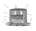
- An embodiment of the invention will hereinafter be described with reference to the accompanying drawing, which is a schematic perspective view of a
generator device 10 according to an embodiment of the invention which can be attached to asurface 12 subjected to thermal exposure. In this respect, thermal exposure should be understood as being a temperature which changes in respect of the freezing temperature of a phase change material which is held in acontainer 16. Thesurface 12 will be subjected to a temperature higher or lower than the freezing temperature of the phase change material for a considerable time. More specifically, the temperature will remain lower than the freezing temperature for a certain time span and then rise above the freezing temperature for another time span. - Attached to the
surface 12 are twothermoelectric generators 14 which convert heat (i.e. a temperature differences) of two opposing sides directly into electrical energy, using a phenomenon called the thermoelectric effect. Thethermoelectric generators 14 are electrically coupled to appropriate devices for converting the electrical energy to the specific needs. These can be sensors and/or transmitters with low energy consumption or energy storing devices such as rechargeable batteries or supercapacitors or a combination of both. - The respective upper sides of the
thermoelectric generators 14 are thermoconductively coupled to thecontainer 16 holding the phase change material. In a preferred embodiment, the phase change material is water but it can also be a mixturd of water with other substances or another material which has a density change when passing the phase change point. - The
generator device 10 includes ahousing 18 which surrounds thecontainer 16 and which includes mountingflanges 20 for fixing thegenerator device 10, especially to thesurface 12. Thehousing 18 includes acover portion 22. Attached to the inner part of thecover portion 22 are a number ofspring elements 24 which act upon apressure plate 26. Thepressure plate 26 presses against the balloon shapedcontainer 16 which has elastically expandable walls, Thecontainer 16 is flattened to some extent and thoroughly pressed against thethermoelectric generators 14. In case the shown embodiment has the phase change material inside thecontainer 16 in a fluid state then in case of solidification the volume of thecontainer 16 increases to some extent (in case of water by about 1 %) which moves thepressure plate 26 against the force ofspring elements 24 some distance towards thecover portion 22. In case of a subsequent liquifaction (melting) due to the reduced volume of the liquid phase change material, thepressure plate 26 is again moved back to the present position due to the force of thespring elements 24. - 10
- generator device
- 12
- surface
- 14
- thermoelectric generators
- 16
- container
- 18
- housing
- 20
- mounting flanges
- 22
- cover portion
- 24
- spring elements
- 26
- pressure plate
Claims (9)
- A device (10) for generating electrical energy comprising at least a thermoelectric generator (14) arranged between a surface (12) subjected to thermal exposure and a container (16) containing a phase change material, characterized in that at least a part of a wall of the container (16) is elastically expandable.
- The device of claim 1, characterized in that said container (16) is completely filled with the phase change material,
- The device of claim 1 or 2, characterized in that the complete container (16) is elastically expandable.
- The device of any of the preceding claims, characterized in that it includes force generating means (24) which bias the container (16) against said thermoelectric generator (14).
- The device of claim 4, characterized in that said force generating means comprise at least one resilient element (24) which is arranged between said container (16) and a device housing (18).
- The device of claim 5, characterized in that said housing (18) surrounds said container (16) and includes a cover portion (22), wherein at least one spring element (24) extending between said cover portion (22) and said elastically expandable container wall (16) effecting a force against said wall.
- The device of any of the preceding claims, characterized in that said container (16) is made of a synthetic rubber (butyl rubber, nitrile rubber, etc)
- The device of any of the preceding claims, characterized in that said container (16) is a balloon.
- The device claim 8, characterized in that said balloon-shaped container (16) has a constant internal pressure.
Priority Applications (1)
| Application Number | Priority Date | Filing Date | Title |
|---|---|---|---|
| EP13186633.7A EP2854191B1 (en) | 2013-09-30 | 2013-09-30 | Thermoelectric Generator with Expandable Container |
Applications Claiming Priority (1)
| Application Number | Priority Date | Filing Date | Title |
|---|---|---|---|
| EP13186633.7A EP2854191B1 (en) | 2013-09-30 | 2013-09-30 | Thermoelectric Generator with Expandable Container |
Publications (3)
| Publication Number | Publication Date |
|---|---|
| EP2854191A1 true EP2854191A1 (en) | 2015-04-01 |
| EP2854191A8 EP2854191A8 (en) | 2015-07-01 |
| EP2854191B1 EP2854191B1 (en) | 2016-05-25 |
Family
ID=49328338
Family Applications (1)
| Application Number | Title | Priority Date | Filing Date |
|---|---|---|---|
| EP13186633.7A Not-in-force EP2854191B1 (en) | 2013-09-30 | 2013-09-30 | Thermoelectric Generator with Expandable Container |
Country Status (1)
| Country | Link |
|---|---|
| EP (1) | EP2854191B1 (en) |
Cited By (1)
| Publication number | Priority date | Publication date | Assignee | Title |
|---|---|---|---|---|
| KR20170002241A (en) | 2015-06-29 | 2017-01-06 | 한국생산기술연구원 | Thermo-electric power generating Apparatus based on expansion materials |
Citations (8)
| Publication number | Priority date | Publication date | Assignee | Title |
|---|---|---|---|---|
| US3607444A (en) * | 1966-12-06 | 1971-09-21 | Siemens Ag | Thermoelectric assembly |
| JP2007116086A (en) * | 2005-06-09 | 2007-05-10 | Toyota Motor Corp | Thermoelectric generator |
| WO2007133069A1 (en) * | 2006-05-15 | 2007-11-22 | Stork Fokker Aesp B.V. | Module comprising a thermoelectric generator, as well as power source |
| DE102009038925A1 (en) * | 2009-08-26 | 2011-03-17 | Eads Deutschland Gmbh | Device for producing electricity for autonomous radio sensor in radio sensor network of e.g. aircraft, has thermal energy storage including recording device for recording thermal volume change of fluid |
| WO2011125231A1 (en) * | 2010-04-07 | 2011-10-13 | トヨタ自動車株式会社 | Vehicle brake device |
| US20120073276A1 (en) * | 2010-09-29 | 2012-03-29 | Gm Global Technology Operations, Inc. | Thermoelectric generators incorporating phase-change materials for waste heat recovery from engine exhaust |
| EP2475019A2 (en) * | 2010-12-15 | 2012-07-11 | The Boeing Company | Power generation using a thermoelectric generator and a phase change material |
| EP2482352A2 (en) * | 2011-02-01 | 2012-08-01 | Simmonds Precision Products, Inc. | Sinkless thermoelectric energy generator |
-
2013
- 2013-09-30 EP EP13186633.7A patent/EP2854191B1/en not_active Not-in-force
Patent Citations (8)
| Publication number | Priority date | Publication date | Assignee | Title |
|---|---|---|---|---|
| US3607444A (en) * | 1966-12-06 | 1971-09-21 | Siemens Ag | Thermoelectric assembly |
| JP2007116086A (en) * | 2005-06-09 | 2007-05-10 | Toyota Motor Corp | Thermoelectric generator |
| WO2007133069A1 (en) * | 2006-05-15 | 2007-11-22 | Stork Fokker Aesp B.V. | Module comprising a thermoelectric generator, as well as power source |
| DE102009038925A1 (en) * | 2009-08-26 | 2011-03-17 | Eads Deutschland Gmbh | Device for producing electricity for autonomous radio sensor in radio sensor network of e.g. aircraft, has thermal energy storage including recording device for recording thermal volume change of fluid |
| WO2011125231A1 (en) * | 2010-04-07 | 2011-10-13 | トヨタ自動車株式会社 | Vehicle brake device |
| US20120073276A1 (en) * | 2010-09-29 | 2012-03-29 | Gm Global Technology Operations, Inc. | Thermoelectric generators incorporating phase-change materials for waste heat recovery from engine exhaust |
| EP2475019A2 (en) * | 2010-12-15 | 2012-07-11 | The Boeing Company | Power generation using a thermoelectric generator and a phase change material |
| EP2482352A2 (en) * | 2011-02-01 | 2012-08-01 | Simmonds Precision Products, Inc. | Sinkless thermoelectric energy generator |
Non-Patent Citations (1)
| Title |
|---|
| D. SAMSON ET AL: "Wireless sensor node powered by aircraft specific thermoelectric energy harvesting", SENSORS AND ACTUATORS A: PHYSICAL, vol. 172, no. 1, 1 December 2011 (2011-12-01), pages 240 - 244, XP055071278, ISSN: 0924-4247, DOI: 10.1016/j.sna.2010.12.020 * |
Cited By (1)
| Publication number | Priority date | Publication date | Assignee | Title |
|---|---|---|---|---|
| KR20170002241A (en) | 2015-06-29 | 2017-01-06 | 한국생산기술연구원 | Thermo-electric power generating Apparatus based on expansion materials |
Also Published As
| Publication number | Publication date |
|---|---|
| EP2854191B1 (en) | 2016-05-25 |
| EP2854191A8 (en) | 2015-07-01 |
Similar Documents
| Publication | Publication Date | Title |
|---|---|---|
| Moser et al. | Thermoelectric energy harvesting from transient ambient temperature gradients | |
| US20120192908A1 (en) | Sinkless thermoelectric energy generator | |
| CN103412592A (en) | Three-level temperature control system of inertia measurement system | |
| EP3113238B1 (en) | Powering aircraft sensors using thermal capacitors | |
| JP2012129519A (en) | Power generation using thermoelectric generator and phase change material | |
| CN206835538U (en) | A kind of electronic equipment for automatically adjusting radiating | |
| WO2013099321A1 (en) | Thermoelectric generator | |
| US10868345B2 (en) | Battery module and use of such a battery module | |
| EP2854191B1 (en) | Thermoelectric Generator with Expandable Container | |
| Elefsiniotis et al. | A novel high-temperature aircraft-specific energy harvester using PCMs and state of the art TEGs | |
| Thiagarajan et al. | Self-propelled sliding bubble motion induced by surface microstructure in pool boiling of a dielectric fluid under microgravity | |
| US20150090436A1 (en) | Fluid based thermal conductivity control | |
| US9303630B2 (en) | Device for converting thermal energy into electric energy in the presence of a hot source | |
| US10497851B2 (en) | Thermoelectric module | |
| Becker et al. | Thermoelectric energy harvesting in aircraft | |
| CN105814390A (en) | Temperature-stabilized storage system with integrated regulated refrigeration | |
| US20160212883A1 (en) | Subsea enclosure system for disposal of generated heat | |
| Nemoto et al. | Output power leveling of on-chip thermoelectric generator using a solid–solid phase change material | |
| KR101222005B1 (en) | Energy harvesting device | |
| US20160241168A1 (en) | Thermal energy harvesting device | |
| CN102735891A (en) | Temperature-difference micro-source applied to measurement of superconductive electrical equipment | |
| Elefsiniotis et al. | Performance of a low temperature energy harvesting device for powering wireless sensor nodes in aircrafts applications | |
| JP5768740B2 (en) | Thermoelectric device and sensor system | |
| US9848508B1 (en) | Cooling systems and synthetic jets configured to harvest energy and vehicles including the same | |
| RU2408919C1 (en) | Thermal stabilisation device of radioelectronic equipment |
Legal Events
| Date | Code | Title | Description |
|---|---|---|---|
| PUAI | Public reference made under article 153(3) epc to a published international application that has entered the european phase |
Free format text: ORIGINAL CODE: 0009012 |
|
| 17P | Request for examination filed |
Effective date: 20130930 |
|
| AK | Designated contracting states |
Kind code of ref document: A1 Designated state(s): AL AT BE BG CH CY CZ DE DK EE ES FI FR GB GR HR HU IE IS IT LI LT LU LV MC MK MT NL NO PL PT RO RS SE SI SK SM TR |
|
| AX | Request for extension of the european patent |
Extension state: BA ME |
|
| RIN1 | Information on inventor provided before grant (corrected) |
Inventor name: ELEFSINIOTIS, ALEXANDROS Inventor name: KOKORAKIS, NIKOLAOS Inventor name: BECKER, THOMAS Inventor name: SCHMID, ULRICH |
|
| RIN1 | Information on inventor provided before grant (corrected) |
Inventor name: ELEFSINIOTIS, ALEXANDROS Inventor name: SCHMID, ULRICH Inventor name: KOKORAKIS, NIKOLAOS Inventor name: BECKER, THOMAS |
|
| RBV | Designated contracting states (corrected) |
Designated state(s): AL AT BE BG CH CY CZ DE DK EE ES FI FR GB GR HR HU IE IS IT LI LT LU LV MC MK MT NL NO PL PT RO RS SE SI SK SM TR |
|
| GRAP | Despatch of communication of intention to grant a patent |
Free format text: ORIGINAL CODE: EPIDOSNIGR1 |
|
| INTG | Intention to grant announced |
Effective date: 20151216 |
|
| GRAS | Grant fee paid |
Free format text: ORIGINAL CODE: EPIDOSNIGR3 |
|
| GRAA | (expected) grant |
Free format text: ORIGINAL CODE: 0009210 |
|
| AK | Designated contracting states |
Kind code of ref document: B1 Designated state(s): AL AT BE BG CH CY CZ DE DK EE ES FI FR GB GR HR HU IE IS IT LI LT LU LV MC MK MT NL NO PL PT RO RS SE SI SK SM TR |
|
| REG | Reference to a national code |
Ref country code: GB Ref legal event code: FG4D |
|
| REG | Reference to a national code |
Ref country code: CH Ref legal event code: EP |
|
| REG | Reference to a national code |
Ref country code: IE Ref legal event code: FG4D Ref country code: AT Ref legal event code: REF Ref document number: 802972 Country of ref document: AT Kind code of ref document: T Effective date: 20160615 |
|
| REG | Reference to a national code |
Ref country code: DE Ref legal event code: R096 Ref document number: 602013007857 Country of ref document: DE |
|
| REG | Reference to a national code |
Ref country code: FR Ref legal event code: PLFP Year of fee payment: 4 |
|
| REG | Reference to a national code |
Ref country code: LT Ref legal event code: MG4D |
|
| REG | Reference to a national code |
Ref country code: NL Ref legal event code: MP Effective date: 20160525 |
|
| PG25 | Lapsed in a contracting state [announced via postgrant information from national office to epo] |
Ref country code: LT Free format text: LAPSE BECAUSE OF FAILURE TO SUBMIT A TRANSLATION OF THE DESCRIPTION OR TO PAY THE FEE WITHIN THE PRESCRIBED TIME-LIMIT Effective date: 20160525 Ref country code: FI Free format text: LAPSE BECAUSE OF FAILURE TO SUBMIT A TRANSLATION OF THE DESCRIPTION OR TO PAY THE FEE WITHIN THE PRESCRIBED TIME-LIMIT Effective date: 20160525 Ref country code: NO Free format text: LAPSE BECAUSE OF FAILURE TO SUBMIT A TRANSLATION OF THE DESCRIPTION OR TO PAY THE FEE WITHIN THE PRESCRIBED TIME-LIMIT Effective date: 20160825 Ref country code: NL Free format text: LAPSE BECAUSE OF FAILURE TO SUBMIT A TRANSLATION OF THE DESCRIPTION OR TO PAY THE FEE WITHIN THE PRESCRIBED TIME-LIMIT Effective date: 20160525 |
|
| REG | Reference to a national code |
Ref country code: AT Ref legal event code: MK05 Ref document number: 802972 Country of ref document: AT Kind code of ref document: T Effective date: 20160525 |
|
| PG25 | Lapsed in a contracting state [announced via postgrant information from national office to epo] |
Ref country code: PT Free format text: LAPSE BECAUSE OF FAILURE TO SUBMIT A TRANSLATION OF THE DESCRIPTION OR TO PAY THE FEE WITHIN THE PRESCRIBED TIME-LIMIT Effective date: 20160926 Ref country code: SE Free format text: LAPSE BECAUSE OF FAILURE TO SUBMIT A TRANSLATION OF THE DESCRIPTION OR TO PAY THE FEE WITHIN THE PRESCRIBED TIME-LIMIT Effective date: 20160525 Ref country code: RS Free format text: LAPSE BECAUSE OF FAILURE TO SUBMIT A TRANSLATION OF THE DESCRIPTION OR TO PAY THE FEE WITHIN THE PRESCRIBED TIME-LIMIT Effective date: 20160525 Ref country code: LV Free format text: LAPSE BECAUSE OF FAILURE TO SUBMIT A TRANSLATION OF THE DESCRIPTION OR TO PAY THE FEE WITHIN THE PRESCRIBED TIME-LIMIT Effective date: 20160525 Ref country code: ES Free format text: LAPSE BECAUSE OF FAILURE TO SUBMIT A TRANSLATION OF THE DESCRIPTION OR TO PAY THE FEE WITHIN THE PRESCRIBED TIME-LIMIT Effective date: 20160525 Ref country code: GR Free format text: LAPSE BECAUSE OF FAILURE TO SUBMIT A TRANSLATION OF THE DESCRIPTION OR TO PAY THE FEE WITHIN THE PRESCRIBED TIME-LIMIT Effective date: 20160826 |
|
| PG25 | Lapsed in a contracting state [announced via postgrant information from national office to epo] |
Ref country code: IT Free format text: LAPSE BECAUSE OF FAILURE TO SUBMIT A TRANSLATION OF THE DESCRIPTION OR TO PAY THE FEE WITHIN THE PRESCRIBED TIME-LIMIT Effective date: 20160525 |
|
| PG25 | Lapsed in a contracting state [announced via postgrant information from national office to epo] |
Ref country code: DK Free format text: LAPSE BECAUSE OF FAILURE TO SUBMIT A TRANSLATION OF THE DESCRIPTION OR TO PAY THE FEE WITHIN THE PRESCRIBED TIME-LIMIT Effective date: 20160525 Ref country code: RO Free format text: LAPSE BECAUSE OF FAILURE TO SUBMIT A TRANSLATION OF THE DESCRIPTION OR TO PAY THE FEE WITHIN THE PRESCRIBED TIME-LIMIT Effective date: 20160525 Ref country code: CZ Free format text: LAPSE BECAUSE OF FAILURE TO SUBMIT A TRANSLATION OF THE DESCRIPTION OR TO PAY THE FEE WITHIN THE PRESCRIBED TIME-LIMIT Effective date: 20160525 Ref country code: EE Free format text: LAPSE BECAUSE OF FAILURE TO SUBMIT A TRANSLATION OF THE DESCRIPTION OR TO PAY THE FEE WITHIN THE PRESCRIBED TIME-LIMIT Effective date: 20160525 Ref country code: SK Free format text: LAPSE BECAUSE OF FAILURE TO SUBMIT A TRANSLATION OF THE DESCRIPTION OR TO PAY THE FEE WITHIN THE PRESCRIBED TIME-LIMIT Effective date: 20160525 |
|
| PG25 | Lapsed in a contracting state [announced via postgrant information from national office to epo] |
Ref country code: PL Free format text: LAPSE BECAUSE OF FAILURE TO SUBMIT A TRANSLATION OF THE DESCRIPTION OR TO PAY THE FEE WITHIN THE PRESCRIBED TIME-LIMIT Effective date: 20160525 Ref country code: BE Free format text: LAPSE BECAUSE OF NON-PAYMENT OF DUE FEES Effective date: 20160525 Ref country code: SM Free format text: LAPSE BECAUSE OF FAILURE TO SUBMIT A TRANSLATION OF THE DESCRIPTION OR TO PAY THE FEE WITHIN THE PRESCRIBED TIME-LIMIT Effective date: 20160525 Ref country code: AT Free format text: LAPSE BECAUSE OF FAILURE TO SUBMIT A TRANSLATION OF THE DESCRIPTION OR TO PAY THE FEE WITHIN THE PRESCRIBED TIME-LIMIT Effective date: 20160525 |
|
| REG | Reference to a national code |
Ref country code: DE Ref legal event code: R097 Ref document number: 602013007857 Country of ref document: DE |
|
| PLBE | No opposition filed within time limit |
Free format text: ORIGINAL CODE: 0009261 |
|
| STAA | Information on the status of an ep patent application or granted ep patent |
Free format text: STATUS: NO OPPOSITION FILED WITHIN TIME LIMIT |
|
| PG25 | Lapsed in a contracting state [announced via postgrant information from national office to epo] |
Ref country code: MC Free format text: LAPSE BECAUSE OF FAILURE TO SUBMIT A TRANSLATION OF THE DESCRIPTION OR TO PAY THE FEE WITHIN THE PRESCRIBED TIME-LIMIT Effective date: 20160525 |
|
| REG | Reference to a national code |
Ref country code: CH Ref legal event code: PL |
|
| 26N | No opposition filed |
Effective date: 20170228 |
|
| PG25 | Lapsed in a contracting state [announced via postgrant information from national office to epo] |
Ref country code: SI Free format text: LAPSE BECAUSE OF FAILURE TO SUBMIT A TRANSLATION OF THE DESCRIPTION OR TO PAY THE FEE WITHIN THE PRESCRIBED TIME-LIMIT Effective date: 20160525 |
|
| REG | Reference to a national code |
Ref country code: IE Ref legal event code: MM4A |
|
| PG25 | Lapsed in a contracting state [announced via postgrant information from national office to epo] |
Ref country code: CH Free format text: LAPSE BECAUSE OF NON-PAYMENT OF DUE FEES Effective date: 20160930 Ref country code: LI Free format text: LAPSE BECAUSE OF NON-PAYMENT OF DUE FEES Effective date: 20160930 Ref country code: IE Free format text: LAPSE BECAUSE OF NON-PAYMENT OF DUE FEES Effective date: 20160930 |
|
| PG25 | Lapsed in a contracting state [announced via postgrant information from national office to epo] |
Ref country code: LU Free format text: LAPSE BECAUSE OF NON-PAYMENT OF DUE FEES Effective date: 20160930 |
|
| REG | Reference to a national code |
Ref country code: FR Ref legal event code: PLFP Year of fee payment: 5 |
|
| PG25 | Lapsed in a contracting state [announced via postgrant information from national office to epo] |
Ref country code: HU Free format text: LAPSE BECAUSE OF FAILURE TO SUBMIT A TRANSLATION OF THE DESCRIPTION OR TO PAY THE FEE WITHIN THE PRESCRIBED TIME-LIMIT; INVALID AB INITIO Effective date: 20130930 |
|
| PG25 | Lapsed in a contracting state [announced via postgrant information from national office to epo] |
Ref country code: MK Free format text: LAPSE BECAUSE OF FAILURE TO SUBMIT A TRANSLATION OF THE DESCRIPTION OR TO PAY THE FEE WITHIN THE PRESCRIBED TIME-LIMIT Effective date: 20160525 Ref country code: HR Free format text: LAPSE BECAUSE OF FAILURE TO SUBMIT A TRANSLATION OF THE DESCRIPTION OR TO PAY THE FEE WITHIN THE PRESCRIBED TIME-LIMIT Effective date: 20160525 Ref country code: CY Free format text: LAPSE BECAUSE OF FAILURE TO SUBMIT A TRANSLATION OF THE DESCRIPTION OR TO PAY THE FEE WITHIN THE PRESCRIBED TIME-LIMIT Effective date: 20160525 Ref country code: MT Free format text: LAPSE BECAUSE OF NON-PAYMENT OF DUE FEES Effective date: 20160930 Ref country code: IS Free format text: LAPSE BECAUSE OF FAILURE TO SUBMIT A TRANSLATION OF THE DESCRIPTION OR TO PAY THE FEE WITHIN THE PRESCRIBED TIME-LIMIT Effective date: 20160525 |
|
| PG25 | Lapsed in a contracting state [announced via postgrant information from national office to epo] |
Ref country code: BG Free format text: LAPSE BECAUSE OF FAILURE TO SUBMIT A TRANSLATION OF THE DESCRIPTION OR TO PAY THE FEE WITHIN THE PRESCRIBED TIME-LIMIT Effective date: 20160525 |
|
| REG | Reference to a national code |
Ref country code: FR Ref legal event code: PLFP Year of fee payment: 6 |
|
| PG25 | Lapsed in a contracting state [announced via postgrant information from national office to epo] |
Ref country code: TR Free format text: LAPSE BECAUSE OF FAILURE TO SUBMIT A TRANSLATION OF THE DESCRIPTION OR TO PAY THE FEE WITHIN THE PRESCRIBED TIME-LIMIT Effective date: 20160525 Ref country code: AL Free format text: LAPSE BECAUSE OF FAILURE TO SUBMIT A TRANSLATION OF THE DESCRIPTION OR TO PAY THE FEE WITHIN THE PRESCRIBED TIME-LIMIT Effective date: 20160525 |
|
| PGFP | Annual fee paid to national office [announced via postgrant information from national office to epo] |
Ref country code: FR Payment date: 20210921 Year of fee payment: 9 |
|
| PGFP | Annual fee paid to national office [announced via postgrant information from national office to epo] |
Ref country code: DE Payment date: 20210920 Year of fee payment: 9 Ref country code: GB Payment date: 20210920 Year of fee payment: 9 |
|
| REG | Reference to a national code |
Ref country code: DE Ref legal event code: R079 Ref document number: 602013007857 Country of ref document: DE Free format text: PREVIOUS MAIN CLASS: H01L0035300000 Ipc: H10N0010130000 |
|
| REG | Reference to a national code |
Ref country code: DE Ref legal event code: R119 Ref document number: 602013007857 Country of ref document: DE |
|
| GBPC | Gb: european patent ceased through non-payment of renewal fee |
Effective date: 20220930 |
|
| PG25 | Lapsed in a contracting state [announced via postgrant information from national office to epo] |
Ref country code: FR Free format text: LAPSE BECAUSE OF NON-PAYMENT OF DUE FEES Effective date: 20220930 Ref country code: DE Free format text: LAPSE BECAUSE OF NON-PAYMENT OF DUE FEES Effective date: 20230401 |
|
| PG25 | Lapsed in a contracting state [announced via postgrant information from national office to epo] |
Ref country code: GB Free format text: LAPSE BECAUSE OF NON-PAYMENT OF DUE FEES Effective date: 20220930 |