EP2853908A1 - Prüfsystem für Hochspannungskomponenten - Google Patents
Prüfsystem für Hochspannungskomponenten Download PDFInfo
- Publication number
- EP2853908A1 EP2853908A1 EP13004654.3A EP13004654A EP2853908A1 EP 2853908 A1 EP2853908 A1 EP 2853908A1 EP 13004654 A EP13004654 A EP 13004654A EP 2853908 A1 EP2853908 A1 EP 2853908A1
- Authority
- EP
- European Patent Office
- Prior art keywords
- test system
- test
- transport containers
- components
- transport
- Prior art date
- Legal status (The legal status is an assumption and is not a legal conclusion. Google has not performed a legal analysis and makes no representation as to the accuracy of the status listed.)
- Granted
Links
Images


Classifications
-
- G—PHYSICS
- G01—MEASURING; TESTING
- G01R—MEASURING ELECTRIC VARIABLES; MEASURING MAGNETIC VARIABLES
- G01R31/00—Arrangements for testing electric properties; Arrangements for locating electric faults; Arrangements for electrical testing characterised by what is being tested not provided for elsewhere
- G01R31/12—Testing dielectric strength or breakdown voltage ; Testing or monitoring effectiveness or level of insulation, e.g. of a cable or of an apparatus, for example using partial discharge measurements; Electrostatic testing
- G01R31/14—Circuits therefor, e.g. for generating test voltages, sensing circuits
-
- G—PHYSICS
- G01—MEASURING; TESTING
- G01R—MEASURING ELECTRIC VARIABLES; MEASURING MAGNETIC VARIABLES
- G01R31/00—Arrangements for testing electric properties; Arrangements for locating electric faults; Arrangements for electrical testing characterised by what is being tested not provided for elsewhere
- G01R31/50—Testing of electric apparatus, lines, cables or components for short-circuits, continuity, leakage current or incorrect line connections
- G01R31/62—Testing of transformers
Definitions
- the invention relates to a test system for high voltage components, comprising a plurality of system components, including at least one inverter and an HV filter.
- High-voltage components such as power transformers
- Power transformers have, for example, a rated power of a few MVA to 100MVA and above. Typical rated voltages range from 10kV to 110kV and above. Therefore, to ensure a fault-free operation of an electrical power distribution network with such high-voltage components at certain time intervals tests, especially the power transformers, makes sense. Such a test is useful or necessary even after a repair or maintenance of a transformer. Such tests provide information about the state of isolation, for example, and also enable the detection of other errors of the relevant high-voltage component.
- High-voltage components such as power transformers have a high weight. Transport of such a power transformer incorporated within an electrical power distribution network into a permanently installed test field in which it could be tested by means of an AC test is excluded in most cases both due to the high transport costs for the respective power transformer as well as lack of redundancy in the respective power distribution network. For this reason, such AC tests of power transformers usually done on site.
- test systems for high-voltage components for example in the range of 10 kV to 110 kV, are usually transported as loose system components in one or more freight containers on site, the system components then being removed from the freight container on site with corresponding lifting tools spent on the component to be tested and there must be very complex connected to a test system.
- test system for high-voltage components of the aforementioned type is characterized in that the system components are at least predominantly distributed over several closed parallelepiped transport containers and firmly arranged therein that they are each manually portable, the transport container through the wall guided standard connection elements for interconnection of the system components.
- the basic idea of the invention is to make a test system for high-voltage components modularized and to arrange respective system components as modules fixed in a respective parallelepipedic transport container, which is equipped with corresponding standard connection elements.
- the individual transport containers can be handled in an advantageous manner and must be connected to each other only on their standard connection elements to a functioning test system on site.
- a construction on site is thereby simplified in an advantageous manner.
- the transport containers then fulfill a protective function not only during transport but also during the test.
- a manual portability of a container automatically means a weight restriction, for example, to a weight range of up to 100kg or 150kg, which is well managed by 3 people. But even a transport container with a weight of, for example, 200kg is quite as portable by 4 people. This means that ultimately the weight of a system component implemented as a module, such as a throttle or a matching transformer, is limited.
- the main field of application of a test system according to the invention in the testing of high voltage components in the range of 10kV to 110kV, because there the weight of the respective system components usually does not exceed a portable weight range.
- test systems for, for example, 380 kV can be configured in this way.
- the modular design of a test system according to the invention also results in high flexibility advantages.
- a needs-based test system can be designed, which is particularly easy to place there even with poor accessibility of a high voltage component to be tested and can be built there with little effort.
- the system components in the respective transport containers in such a way that sufficiently large isolation distances to live or grounded components are ensured.
- inverter modules are typically already arranged in a housing, which in turn is arranged in a transport container, so that no insulation problems are to be expected, for example, in a matching transformer to appropriate heights, for example, to the walls of the transport container, to pay attention.
- the insulation distances required within a transport container can be reduced by appropriate insulation measures, such as an extension of a creepage path or shields.
- plug-in connection elements are used as standard connection elements for electrical connections, for example MC or Hartling connections. These have established themselves as a respective standard and have correspondingly good connection properties. Electrical connections can be, for example, both data connections for controlling the individual system components and lines for transmitting, for example, a test voltage.
- test system is provided as a system component arranged in a separate transport container cooling device, which by means of hose connections can be connected to at least one of the other transport container, so that a system component arranged therein can be cooled thereby.
- Inverters for example, emit considerable heat loss during their operation, which must be dissipated accordingly. Within certain limits, these can be dissipated, for example, by means of a ventilation grille provided in a wall of a transport container, but the thermal connection with a cooling system can be regarded as significantly more effective.
- test system With the extremely high flexibility of a test system according to the invention becomes clear. If, for example, a test is to be carried out under very moderate climatic conditions, for example in winter, it may be possible to dispense with a cooling system, whereas in very extreme climatic conditions, even a plurality of cooling systems may be provided.
- a matching transformer is provided as one of the system components.
- An adapting transformer is also a component which can be arranged inside a transport container.
- a system component is distributed over a plurality of transport containers.
- This can be, for example, several inverter modules connected in series or in parallel, by which together a system component having a correspondingly higher power is formed.
- system components such as HV filters or matching transformers can be distributed as needed to several interconnected modules, which are arranged in respective transport containers.
- a plurality of system components are arranged in a single transport container. This is particularly useful for smaller system components, which can be arranged together and functionally belong together.
- An example of this may be, for example, a control computer for a test system, which is arranged together with an evaluation device in one and the same transport container.
- a further variant of the invention is characterized in that at least some of the transport containers are identical in their outer geometry. As a result, these can be arranged in a space-saving manner both during transport and during operation of the test system, for example in the form of a stack.
- At least some of the transport containers can be stacked in a form-fitting manner. This means, for example, that corresponding stacking troughs or the like are provided, so that a mutual horizontal fixation of stacked transport containers is provided.
- respective corresponding standard connecting elements of different transport containers to be connected are arranged in their respective cover or bottom regions in such a way that a respective connection is already formed in the stacked state of the transport container.
- the system components are connected to one another via the standard connection elements. If necessary, it is also possible or isolation technology even required to operate some components such as a surge arrester or the like not in a transport container but stand alone in the test setup.
- transport containers have outer carrying handles, with which the manual transport is advantageously simplified.
- Transport containers are made for example of aluminum, which may have a profile structure to increase the stability.
- FIG. 1 shows an exemplary test system for high voltage components in a three-dimensional view 10.
- the test system has four transport containers 12, 14, 16, 16, wherein arranged in their interior system components by means of respective connections electrically 20, 22, 34 are interconnected.
- the test system has two inverters, an HV filter and a matching transformer, which, however, can not be directly removed from the figure due to the transport container, which is almost identical on the outside.
- a power supply of the test system via electrical connection lines is likewise not shown.
- a test voltage is applied to the standard connecting elements of the fourth transport container 18 functioning as outputs in the test mode, which test voltage is conducted via the connection 24, 26 and via respective voltage dividers 30 to a high-voltage transformer to be tested.
- An operator 32 shown in scale, shows the dimensions of this exemplary testing system. It is readily apparent that the size of the transport container can be carried well by 2 to 3 people and thus can be built on site particularly flexible and without the aid of lifting tools or the like. A stacked arrangement of transport containers is not shown in this figure. Care was taken in the distribution and arrangement of the respective system components on or in the respective transport containers that a portable weight is not exceeded.
- FIG. 2 shows a sectional view 40 through a first exemplary transport container 42.
- a first exemplary transport container 42 In the cuboid transport container 42 is arranged in a likewise cuboidal housing inverter 58 is provided.
- This is electrically connected by means of internal connecting lines 48, 50 with provided on the side walls of the transport container 42 standard connecting elements 44, 46, which represent, for example, a respective coupling piece for connecting a connecting line.
- standard connecting elements 44, 46 represent, for example, a respective coupling piece for connecting a connecting line.
- Any electrical control lines to a control system are not shown, but these are also, for example, introduced by not shown standard connection elements in the transport container, but it is also possible, for example, a fiber optic or wireless connection.
- a heat exchanger 60 of a cooling system is provided above to dissipate the heat output.
- the heat exchanger is part of a cooling system to be formed with a closed cooling circuit, which in addition to a cooling unit in an adjacent transport container, not shown, also includes inner connecting pipes 56 and standard connecting elements 52, 54 for inlet and outlet of a cooling medium.
- FIG. 3 shows an exterior view 70 of a second exemplary transport container 72. This has on one of its side walls on two standard connecting elements 74, 76 of a coolant inlet and outlet for connection of a respective connecting hose. On two opposite side walls in each case a carrying handle 84 are provided, of which, however, only one is visible reasons of drawing.
- a cuboid recess or depression is provided, from which in turn three standard connecting elements 78 protrude.
- a corresponding mating connector is provided so that in stacks of similar transport container 72 automatically a respective compound is formed.
- respectively form-fitting corresponding stacking troughs 82 are provided on the top and bottom.
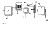
- FIG. 4 shows an electrical interconnect 90 of an exemplary test system with its respective system components.
- An inverter 92 fed via a three-phase supply voltage generates an alternating voltage of variable frequency. This is supplied to a matching transformer 94 and transformed to a higher voltage level.
- the step-up voltage is filtered by means of an HV filter 98 and fed via a throttle 96 to a transformer 102 to be tested.
- a voltage divider also serves as a filter and divides the voltage down to a measurable value.
- a voltage measuring device not shown, is provided, the determined voltage values of which are fed to an evaluation system (not shown), for example a suitable data processing system.
Landscapes
- Physics & Mathematics (AREA)
- General Physics & Mathematics (AREA)
- Engineering & Computer Science (AREA)
- Power Engineering (AREA)
- Testing Relating To Insulation (AREA)
Abstract
Description
- Die Erfindung betrifft ein Prüfsystem für Hochspannungskomponenten, umfassend mehrere Systemkomponenten, darunter wenigstens einen Wechselrichter und einen HV-Filter.
- Es ist allgemein bekannt, dass Hochspannungskomponenten, wie beispielsweise Leistungstransformatoren, einem Alterungsprozess unterworfen sind, welcher insbesondere die elektrische Isolation betrifft. Leistungstransformatoren weisen beispielsweise eine Nennleistung von einigen MVA bis 100MVA und darüber auf. Typische Nennspannungen liegen im Bereich von 10kV bis 110kV und darüber. Von daher sind zur Sicherstellung eines fehlerfreien Betriebes eines elektrischen Energieverteilungsnetzes mit derartigen Hochspannungskomponenten in bestimmten Zeitintervallen Prüfungen, insbesondere der Leistungstransformatoren, sinnvoll. Eine derartige Prüfung ist auch nach einer Reparatur oder Wartung eines Transformators sinnvoll bzw. erforderlich. Derartige Prüfungen geben Aufschluss über den Zustand beispielsweise der Isolation und ermöglichen auch die Detektion anderer Fehler der betreffenden Hochspannungskomponente.
- Hochspannungskomponenten wie Leistungstransformatoren weisen ein hohes Gewicht auf. Ein Transport eines derartigen innerhalb eines elektrischen Energieverteilungsnetzes eingebauten Leistungstransformators in ein fest installiertes Prüffeld, in welchem dieser mittels einer Wechselspannungsprüfung geprüft werden könnte, ist sowohl aufgrund des hohen Transportaufwandes für den jeweiligen Leistungstransformator als auch aufgrund mangelnder Redundanz im jeweiligen Energieverteilungsnetz in den allermeisten Fällen ausgeschlossen. Aus diesem Grund erfolgen derartige Wechselspannungsprüfungen von Leistungstransformatoren zumeist vor Ort.
- Als nachteilig erweist es sich, dass bekannte Prüfsysteme für Hochspannungskomponenten, beispielsweise im Bereich von 10kV bis 110kV, zumeist als lose Systemkomponenten in einem oder auch mehreren Frachtcontainern vor Ort transportiert werden, wobei die Systemkomponenten dann vor Ort mit entsprechenden Hubwerkzeugen aus dem Frachtcontainer entfernt, bis zur zu prüfenden Komponente verbracht und dort sehr aufwändig zu einem Prüfsystem verschaltet werden müssen.
- Im Stand der Technik sind weiterhin Testsysteme für Höchstspannungskomponenten, beispielsweise im Bereich von 110kV bis 380kV, bekannt, welche komplett in einem Frachtcontainer integriert sind. Ein derartiger Frachtcontainer ist jedoch zumindest für den Test von kleineren oder mittleren Hochspannungskomponenten, welche zumeist in eher beengten Raumverhältnissen angeordnet sind, aufgrund seiner Größe zumeist nicht direkt zum Prüfort verbringbar. Ein Beispiel für ein derartiges System ist in der
EP 2133704 B1 beschrieben. - Ausgehend von diesem Stand der Technik ist es Aufgabe der Erfindung, ein Prüfsystem für Hochspannungskomponenten bereitzustellen, welches einfach transportierbar ist, sich auch unter beengten Raumverhältnissen besonders einfach vor Ort aufbauen lässt und welches darüber hinaus besonders flexibel handhabbar ist.
- Diese Aufgabe wird gelöst von einem Prüfsystem für Hochspannungskomponenten der eingangs genannten Art. Dieses ist dadurch gekennzeichnet, dass die Systemkomponenten zumindest überwiegend derart auf mehrere geschlossene quaderähnliche Transportbehälter verteilt und fest darin angeordnet sind, dass diese jeweils manuell tragbar sind, wobei die Transportbehälter durch deren Wandung geführte Standardverbindungselemente zur Verschaltung der Systemkomponenten aufwiesen.
- Die Grundidee der Erfindung besteht darin, ein Prüfsystem für Hochspannungskomponenten modularisiert zu gestalten und jeweilige Systemkomponenten als Module fest in einem jeweiligen quaderähnlichen Transportbehälter anzuordnen, welcher mit entsprechenden Standardverbindungselementen ausgestattet ist. So lassen sich in vorteilhafter Weise die einzelnen Transportbehälter einfach handhaben und müssen vor Ort lediglich noch über ihre Standardverbindungselemente zu einem funktionierenden Prüfsystem miteinander verbunden werden. Ein Aufbau vor Ort ist hierdurch in vorteilhafter Weise vereinfacht. Die Transportbehälter erfüllen dann nicht nur während des Transportes sondern auch während der Prüfung eine Schutzfunktion.
- Eine manuelle Tragbarkeit eines Behälters bedeutet automatisch auch eine Gewichtsbeschränkung, beispielsweise auf einen Gewichtsbereich von maximal 100kg oder 150kg, welcher von 3 Personen durchaus noch zu bewältigen ist. Aber auch ein Transportbehälter mit einem Gewicht von beispielsweise 200kg ist durchaus noch als von 4 Personen tragbar anzusehen. Dies bedeutet, dass letztendlich das Gewicht einer als ein Modul ausgeführten Systemkomponente wie einer Drossel oder einem Anpasstransformator begrenzt ist. Damit liegt das Hauptanwendungsgebiet eines erfindungsgemäßen Prüfsystems bei der Prüfung von Hochspannungskomponenten im Bereich von 10kV bis 110kV, weil dort das Gewicht der jeweiligen Systemkomponenten in der Regel einen tragbaren Gewichtsbereich nicht übersteigt. Je nach Prüfanwendung lassen sich aber auch Prüfsysteme für beispielsweise 380kV derartig ausgestalten.
- Darüber liegende Spannungsbereiche von beispielsweise 380kV und höher, bei welchen die jeweilige Systemkomponenten eines Prüfsystems deutlich schwerer sein können als der tragbare Gewichtsbereich, sind jedoch auch eher uninteressant für ein erfindungsgemäßes Prüfsystem, weil in solchen Spannungsebenen zumeist eine so gute örtliche Zugänglichkeit einer zu testenden Hochspannungskomponente gegeben ist, dass beispielsweise ein Frachtcontainer mit fest integriertem Prüfsystem problemlos direkt an diese verbringbar ist.
- Durch den modularen Aufbau eines erfindungsgemäßen Prüfsystems ergeben sich zudem hohe Flexibilitätsvorteile. So lässt sich beispielsweise durch entsprechende elektrische Parallelschaltung von in jeweiligen Transportbehältern angeordneten standardisierten Wechselrichtermodulen ein Wechselrichter mit entsprechend bedarfsgerecht erhöhter Leistung als Systemkomponente bilden. Auch die wahlweise ein- oder mehrphasige Ausführung eines erfindungsgemäßen Prüfsystems ist damit in vorteilhafter Weise ermöglicht. Somit lässt sich je nach durchzuführender Prüfung aus jeweiligen zur Verfügung stehenden Modulen ein bedarfsgerechtes Prüfsystem konzipieren, welches besonders einfach auch bei schlechter Zugänglichkeit einer zu prüfenden Hochspannungskomponente dorthin verbringbar und mit wenig Aufwand dort aufbaubar ist.
- Um den sicheren Betrieb des Prüfsystems mit in den Transportbehältern angeordneten Systemkomponenten zu ermöglichen ist es erfindungsgemäß in einer Variante vorgesehen, die Systemkomponenten derart in den jeweiligen Transportbehältern anzuordnen, dass genügend große Isolationsabstände zu spannungsführenden beziehungsweise geerdeten Bauteilen gewährleistet sind. Während beispielsweise Wechselrichtermodule typischerweise bereits in einem Gehäuse angeordnet sind, welches seinerseits in einem Transportbehälter angeordnet ist, so dass keine Isolationsprobleme zu erwarten sind, ist beispielsweise bei einem Anpasstransformator auf entsprechende Abstände, beispielsweise zu den Wandungen des Transportbehälters, zu achten. Die innerhalb eines Transportbehälters benötigten Isolationsabstände lassen sich jedoch durch entsprechende Isolationsmaßnahmen, wie beispielsweise einer Verlängerung eines Kriechweges oder Schirmungen, reduzieren.
- Gemäß einer weiteren Ausgestaltungsform des erfindungsgemäßen Prüfsystems werden als Standardverbindungselemente für elektrische Verbindungen steckbare Verbindungselemente verwendet, beispielsweise MC oder Hartling Verbindungen. Diese haben sich als ein jeweiliger Standard etabliert und weisen entsprechend gute Verbindungseigenschaften auf. Elektrische Verbindungen können beispielsweise sowohl Datenverbindungen zum Steuern der einzelnen Systemkomponenten sein als auch Leitungen zur Übertragung von beispielsweise einer Prüfspannung.
- Gemäß einer besonders bevorzugten Ausgestaltungsform des erfindungsgemäßen Prüfsystems ist als eine Systemkomponente eine in einem separaten Transportbehälter angeordnete Kühlvorrichtung vorgesehen, welche mittels Schlauchverbindungen mit wenigstens einem der anderen Transportbehälter verbindbar ist, so dass eine darin angeordnete Systemkomponente dadurch kühlbar ist. Wechselrichter beispielsweise geben während ihres Betriebes eine nicht unerhebliche Verlustwärme ab, welche entsprechend abzuführen ist. In gewissen Grenzen lässt sich diese beispielsweise mittels eines in einer Wandung eines Transportbehälters vorgesehenen Lüftungsgitters abführen, die wärmetechnische Verschaltung mit einem Kühlsystem ist jedoch als deutlich effektiver anzusehen.
- Auch hier wird die außerordentlich hohe Flexibilität eines erfindungsgemäßen Prüfsystems deutlich. Wenn eine Prüfung beispielsweise unter sehr gemäßigten Klimabedingungen, beispielsweise im Winter, erfolgen soll kann gegebenenfalls auf ein Kühlsystem verzichtet werden, wohingegen unter sehr extremen Klimabedingungen sogar mehrere Kühlsysteme vorgesehen sein können.
- In einer weiterhin bevorzugten Ausgestaltungsform des erfindungsgemäßen Prüfsystems ist als eine der Systemkomponenten ein Anpasstransformator vorgesehen. Durch Verwendung eines Anpasstransformators lässt sich das Spannungsniveau einer von einem oder mehreren Wechselrichtern erzeugten Prüfspannung bedarfsgerecht erhöhen. Ein Anpasstransformator ist ebenfalls eine Komponente, welche sich innerhalb eines Transportbehälters anordnen lässt.
- Gemäß einer weiteren erfindungsgemäßen Variante des Prüfsystems ist eine Systemkomponente auf mehrere Transportbehälter verteilt. Dies können beispielsweise mehrere in Reihe oder parallel geschaltete Wechselrichtermodule sein, durch welche gemeinsam eine Systemkomponente mit entsprechend höherer Leistung gebildet ist. Aber auch Systemkomponenten wie HV-Filter oder Anpasstransformatoren lassen sich bedarfsweise auf mehrere miteinander verschaltete Module verteilen, welche in jeweiligen Transportbehältern angeordnet sind. Hierdurch lassen sich letztendlich auch Systemkomponenten realisieren, deren Gesamtgewicht ein manuell tragbares Gewicht übersteigt. Die Gesamtleistung eines Prüfsystems kann damit in vorteilhafter Weise gesteigert werden.
- Einer weiteren Erfindungsvariante folgend ist auch die Möglichkeit vorgesehen, dass mehrere Systemkomponenten in einem einzigen Transportbehälter angeordnet sind. Dies ist insbesondere bei kleineren Systemkomponenten sinnvoll, welche gut zusammen anordenbar sind und funktionell zusammengehören. Ein Beispiel hierfür kann beispielsweise ein Steuerrechner für ein Prüfsystem sein, welcher zusammen mit einer Auswertevorrichtung in ein und demselben Transportbehälter angeordnet ist.
- Eine weitere Erfindungsvariante ist dadurch gekennzeichnet, dass zumindest einige der Transportbehälter von ihrer äußeren Geometrie her identisch sind. Dadurch lassen diese sich sowohl beim Transport als auch beim Betrieb des Prüfsystems platzsparend anordnen, beispielsweise in Form eines Stapels.
- Um eine Stapelbarkeit weiter zu verbessern ist erfindungsgemäß in einer Variante vorgesehen, dass zumindest einige der Transportbehälter formschlüssig stapelbar sind. Dies bedeutet beispielsweise, dass entsprechende Stapelmulden oder dergleichen vorgesehen sind, so dass eine gegenseitige horizontale Fixierung übereinander gestapelter Transportbehälter gegeben ist.
- Gemäß einer weiterhin bevorzugten Variante des Prüfsystems sind jeweilige zu verbindende korrespondierende Standardverbindungselemente verschiedener Transportbehälter derart in deren jeweiligen Deckel- beziehungsweise Bodenbereichen angeordnet, dass im gestapelten Zustand der Transportbehälter bereits eine jeweilige Verbindung gebildet ist. Somit wird eine Verbindung verschiedener Transportbehälter weiter vereinfacht, weil bereits beim Stapelvorgang automatisch eine entsprechende Verbindung gebildet ist, ohne dass ein sonst übliches Verbindungsstück, beispielsweise ein Kabel- oder Schlauchstück, erforderlich sind.
- Um die volle Betriebsfähigkeit eines erfindungsgemäßen Prüfsystems herzustellen sind die Systemkomponenten über die Standardverbindungselemente miteinander verbunden. Gegebenenfalls ist es auch möglich beziehungsweise isolationstechnisch sogar erforderlich, einige Komponenten wie einen Überspannungsableiter oder dergleichen nicht in einem Transportbehältnis sondern alleinstehend im Prüfaufbau zu betreiben.
- Einer weiteren Erfindungsvariante folgend weisen zumindest einige der Transportbehälter äußere Tragegriffe auf, mit welchen der manuelle Transport vorteilhaft vereinfacht ist. Transportbehälter sind beispielsweise aus Aluminium gefertigt, welches zur Erhöhung der Stabilität eine Profilstruktur aufweisen kann.
- Weitere vorteilhafte Ausgestaltungsmöglichkeiten sind den weiteren abhängigen Ansprüchen zu entnehmen.
- Anhand der in den Zeichnungen dargestellten Ausführungsbeispiele sollen die Erfindung, weitere Ausführungsformen und weitere Vorteile näher beschrieben werden.
- Es zeigen:
- Fig. 1
- ein exemplarisches Prüfsystem für Hochspannungskomponenten,
- Fig. 2
- eine Schnittansicht durch einen ersten exemplarischen Transportbehälter,
- Fig. 3
- eine Außenansicht von einem zweiten exemplarischen Transportbehälter und
- Fig. 4
- eine Verschaltung eines exemplarischen Prüfsystems.
-
Figur 1 zeigt ein exemplarisches Prüfsystem für Hochspannungskomponenten in einer dreidimensionalen Ansicht 10. Das Prüfsystem weist vier Transportbehälter 12, 14, 16, 16 auf, wobei in deren Inneren angeordnete Systemkomponenten mittels jeweiliger Verbindungen elektrisch 20, 22, 34 miteinander verbunden sind. Das Prüfsystem weist als Systemkomponenten zwei Wechselrichter, einen HV-Filter sowie einen Anpasstransformator auf, was der Figur aufgrund der außen nahezu identisch ausgestalteten Transportbehälter jedoch nicht direkt entnehmbar ist. Eine über elektrische Verbindungsleitungen erfolgende Energieversorgung des Prüfsystems ist ebenfalls nicht gezeigt. An den als Ausgänge fungierenden Standardverbindungselementen des vierten Transportbehälters 18 liegt im Prüfbetrieb eine Prüfspannung an, welche mittels der Verbindung 24, 26 und über jeweilige Spannungsteiler 30 zu einem zu prüfenden Hochspannungstransformator geführt wird. - Eine als Größenmaßstab dargestellte Bedienperson 32 zeigt die Dimensionen dieses exemplarischen Prüfsystems. Es ist gut ersichtlich, dass die Transportbehälter von der Größe her gut von 2 bis 3 Personen getragen werden können und damit besonders flexibel und ohne Zuhilfenahme von Hubwerkzeugen oder dergleichen vor Ort aufgebaut werden können. Eine gestapelte Anordnung von Transportbehältern ist in dieser Figur nicht dargestellt. Bei der Verteilung und Anordnung der jeweiligen Systemkomponenten auf beziehungsweise in den jeweiligen Transportbehältern wurde darauf geachtet, dass ein tragbares Gewicht nicht überschritten wird.
-
Figur 2 zeigt eine Schnittansicht 40 durch einen ersten exemplarischen Transportbehälter 42. In dem quaderförmigen Transportbehälter 42 ist ein in einem ebenfalls quaderförmigen Gehäuse angeordneter Wechselrichter 58 vorgesehen. Dieser ist elektrisch mittels interner Verbindungsleitungen 48, 50 mit an den Seitenwandungen des Transportbehälters 42 vorgesehenen Standardverbindungselementen 44, 46 verbunden, welche beispielsweise ein jeweiliges Kupplungsstück zum Anschluss einer Verbindungsleitung darstellen. Eventuelle elektrische Steuerleitungen zu einem Steuersystem sind nicht dargestellt, diese sind aber beispielsweise ebenfalls durch nicht gezeigte Standardverbindungselemente in den Transportbehälter einführbar, es ist aber auch beispielsweise eine Glasfaser- oder Funkverbindung möglich. - Da der Wechselrichter 58 im Prüfbetrieb eine aus elektrischen Verlusten resultierende Wärmeleistung abgibt, ist oberhalb ein Wärmetauscher 60 eines Kühlsystems vorgesehen, um die Wärmeleistung abzuführen. Der Wärmetauscher ist Teil eines zu bildenden Kühlsystems mit geschlossenem Kühlkreislauf, welcher neben einem Kühlaggregat in einem nicht gezeigten benachbarten Transportbehälter auch innere Verbindungsrohre 56 und Standardverbindungselemente 52, 54 für Zu- und Ablauf eines Kühlmediums umfasst.
-
Figur 3 zeigt eine Außenansicht 70 von einem zweiten exemplarischen Transportbehälter 72. Dieser weist an einer seiner Seitenwandungen zwei Standardverbindungselemente 74, 76 eines Kühlmittelein- beziehungsweise Auslasses zum Anschluss eines jeweiligen Verbindungsschlauches auf. An zwei gegenüberliegenden Seitenwandungen sind jeweils ein Tragegriff 84 vorgesehen, von denen aus zeichnerischen gründen jedoch nur einer sichtbar ist. - Im Deckelbereich des Transportbehälters 72 ist eine quaderähnliche Ausnehmung beziehungsweise Vertiefung vorgesehen, aus welcher ihrerseits drei Standardverbindungselemente 78 herausragen. Nicht sichtbar auf der Unterseite des Transportbehälters 72 ist ein entsprechendes Gegenverbindungsstück vorgesehen, so dass bei Stapeln gleichartiger Transportbehälter 72 automatisch eine jeweilige Verbindung gebildet ist. Um bei einem derartigen Stapel von Transportbehältern 72 ein gegenseitiges horizontales Verrutschen zu vermeiden, sind an der Ober- und Unterseite jeweils formschlüssig korrespondierende Stapelmulden 82 vorgesehen.
-
Figur 4 zeigt eine elektrische Verschaltung 90 eines exemplarischen Prüfsystems mit seinen jeweiligen Systemkomponenten. Ein über eine dreiphasige Versorgungsspannung gespeister Wechselrichter 92 erzeugt eine Wechselspannung variabler Frequenz. Diese wird einem Anpasstransformator 94 zugeführt und auf ein höheres Spannungsniveau transformiert. Die hochtransformierte Spannung wird mittels eines HV Filters 98 gefiltert und über eine Drossel 96 einem zu prüfenden Transformator 102 zugeführt. Ein Spannungsteiler dient ebenfalls als Filter und teilt die Spannung auf einen messbaren Wert runter. Am Spannungsabgriff ist eine nicht gezeigte Spannungsmessvorrichtung vorgesehen, deren ermittelte Spannungswerte einem nicht gezeigten Auswertesystem zugeführt werden, beispielsweise einer geeigneten Datenverarbeitungsanlage. -
- 10
- exemplarisches Prüfsystem für Hochspannungskomponenten
- 12
- erster Transportbehälter von Prüfsystem
- 14
- zweiter Transportbehälter von Prüfsystem
- 16
- dritter Transportbehälter von Prüfsystem
- 18
- vierter Transportbehälter von Prüfsystem
- 20
- erste Verbindungen zwischen Standardverbindungselementen
- 22
- zweite Verbindungen zwischen Standardverbindungselementen
- 24
- dritte Verbindungen zwischen Standardverbindungselementen
- 26
- vierte Verbindungen zwischen Standardverbindungselementen
- 28
- zu prüfender Hochspannungstransformator
- 30
- Spannungsteiler
- 32
- Bedienperson
- 34
- fünfte Verbindungen zwischen Standardverbindungselementen
- 40
- Schnittansicht durch ersten exemplarischen Transportbehälter
- 42
- erster exemplarischer Transportbehälter
- 44
- erste Standardverbindungselemente
- 46
- zweite Standardverbindungselemente
- 48
- erste interne Verbindungen
- 50
- zweite interne Verbindungen
- 52
- Standardverbindungselement von Kühlmitteleinlass
- 54
- Standardverbindungselement von Kühlmittelauslass
- 56
- Verbindungsrohre
- 58
- Wechselrichter
- 60
- Wärmetauscher
- 70
- Außenansicht von zweitem exemplarischen Transportbehälter
- 72
- zweiter exemplarischer Transportbehälter
- 74
- Standardverbindungselement von Kühlmitteleinlass
- 76
- Standardverbindungselement von Kühlmittelauslass
- 78
- exemplarische Standardverbindungselemente
- 80
- Ausnehmung in Deckelbereich von zweitem Transportbehälter
- 82
- Staplelmulden
- 84
- Tragegriff
- 90
- Verschaltung eines exemplarischen Prüfsystems
- 92
- Wechselrichter
- 94
- Anpasstransformator
- 96
- Drossel
- 98
- HV-Filter
- 100
- Spannungsteiler
- 102
- zu prüfender Hochspannungstransformator
Claims (12)
- Prüfsystem (10, 90) für Hochspannungskomponenten, umfassend mehrere Systemkomponenten, darunter wenigstens einen Wechselrichter (58, 92) und einen HV-Filter (98),
dadurch gekennzeichnet,
dass die Systemkomponenten zumindest überwiegend derart auf mehrere geschlossene quaderähnliche Transportbehälter (12, 14, 16, 18, 42, 72) verteilt und fest darin angeordnet sind, dass diese jeweils manuell tragbar sind, wobei die Transportbehälter (12, 14, 16, 18, 42, 72) durch deren Wandung geführte Standardverbindungselemente (44, 46, 52, 54, 74, 76, 78) zur Verschaltung der Systemkomponenten aufweisen. - Prüfsystem nach Anspruch 1, dadurch gekennzeichnet, dass die Systemkomponenten derart in den jeweiligen Transportbehältern (12, 14, 16, 18, 42, 72) angeordnet sind, dass genügend große Isolationsabstände zu spannungsführenden beziehungsweise geerdeten Bauteilen gewährleistet sind und so im verschalteten Zustand ein sicherer Prüfbetrieb gewährleistet ist.
- Prüfsystem nach Anspruch 1 oder 2, dadurch gekennzeichnet, dass als Standardverbindungselemente (44, 46, 52, 54, 74, 76, 78) für elektrische Verbindungen steckbare Verbindungselemente verwendet werden (beispielsweise MC oder Hartling).
- Prüfsystem nach einem der vorherigen Ansprüche, dadurch gekennzeichnet, dass als eine Systemkomponente eine in einem separaten Transportbehälter (12, 14, 16, 18, 42, 72) angeordnete Kühlvorrichtung vorgesehen ist, welche mittels Schlauchverbindungen mit wenigstens einem der anderen Transportbehälter (12, 14, 16, 18, 42, 72) verbindbar ist, so dass eine darin angeordnete Systemkomponente dadurch kühlbar ist.
- Prüfsystem nach einem der vorherigen Ansprüche, dadurch gekennzeichnet, dass als eine der Systemkomponenten ein Anpasstransformator (94) vorgesehen ist.
- Prüfsystem nach einem der vorherigen Ansprüche, dadurch gekennzeichnet, dass eine Systemkomponente auf mehrere Transportbehälter (12, 14, 16, 18, 42, 72) verteilt ist.
- Prüfsystem nach einem der vorherigen Ansprüche, dadurch gekennzeichnet, dass mehrere Systemkomponenten in einem einzigen Transportbehälter (12, 14, 16, 18, 42, 72) angeordnet sind.
- Prüfsystem nach einem der vorherigen Ansprüche, dadurch gekennzeichnet, dass zumindest einige der Transportbehälter (12, 14, 16, 18, 42, 72) von Ihrer äußeren Geometrie her identisch sind.
- Prüfsystem nach einem der vorherigen Ansprüche, dadurch gekennzeichnet, dass zumindest einige der Transportbehälter formschlüssig stapelbar sind.
- Prüfsystem nach Anspruch 9, dadurch gekennzeichnet, dass jeweilige zu verbindende korrespondierende Standardverbindungselemente (44, 46, 52, 54, 74, 76, 78) verschiedener Transportbehälter (12, 14, 16, 18, 42, 72) derart in deren jeweiligen Deckel- beziehungsweise Bodenbereichen angeordnet sind, dass im gestapelten Zustand der Transportbehälter (12, 14, 16, 18, 42, 72) eine jeweilige Verbindung gebildet ist.
- Prüfsystem nach einem der vorherigen Ansprüche, dadurch gekennzeichnet, dass die Systemkomponenten über die Standardverbindungselemente miteinander verbunden sind.
- Prüfsystem nach einem der vorherigen Ansprüche, dadurch gekennzeichnet, dass zumindest einige der Transportbehälter (12, 14, 16, 18, 42, 72) äußere Tragegriffe (84) aufweisen.
Priority Applications (1)
| Application Number | Priority Date | Filing Date | Title |
|---|---|---|---|
| EP13004654.3A EP2853908B1 (de) | 2013-09-25 | 2013-09-25 | Prüfsystem für Hochspannungskomponenten |
Applications Claiming Priority (1)
| Application Number | Priority Date | Filing Date | Title |
|---|---|---|---|
| EP13004654.3A EP2853908B1 (de) | 2013-09-25 | 2013-09-25 | Prüfsystem für Hochspannungskomponenten |
Publications (2)
| Publication Number | Publication Date |
|---|---|
| EP2853908A1 true EP2853908A1 (de) | 2015-04-01 |
| EP2853908B1 EP2853908B1 (de) | 2021-03-31 |
Family
ID=49263094
Family Applications (1)
| Application Number | Title | Priority Date | Filing Date |
|---|---|---|---|
| EP13004654.3A Active EP2853908B1 (de) | 2013-09-25 | 2013-09-25 | Prüfsystem für Hochspannungskomponenten |
Country Status (1)
| Country | Link |
|---|---|
| EP (1) | EP2853908B1 (de) |
Cited By (1)
| Publication number | Priority date | Publication date | Assignee | Title |
|---|---|---|---|---|
| EP3447507A1 (de) * | 2017-08-22 | 2019-02-27 | Alpha Elektrotechnik AG | Mobile teilentladung-prüfeinrichtung |
Citations (4)
| Publication number | Priority date | Publication date | Assignee | Title |
|---|---|---|---|---|
| WO2007001024A1 (ja) * | 2005-06-29 | 2007-01-04 | Hitachi, Ltd. | 電力供給装置およびその組立方法 |
| EP2133704B1 (de) | 2008-06-12 | 2011-08-31 | ABB Technology AG | Prüfanordnung zur Wechselspannungsprüfung von elektrischen Hochspannungskomponenten |
| EP2590185A1 (de) * | 2011-11-02 | 2013-05-08 | ABB Technology AG | Hochspannungstransformatormodul |
| EP2590490A1 (de) * | 2011-11-02 | 2013-05-08 | ABB Technology AG | Prüfcontainer |
-
2013
- 2013-09-25 EP EP13004654.3A patent/EP2853908B1/de active Active
Patent Citations (4)
| Publication number | Priority date | Publication date | Assignee | Title |
|---|---|---|---|---|
| WO2007001024A1 (ja) * | 2005-06-29 | 2007-01-04 | Hitachi, Ltd. | 電力供給装置およびその組立方法 |
| EP2133704B1 (de) | 2008-06-12 | 2011-08-31 | ABB Technology AG | Prüfanordnung zur Wechselspannungsprüfung von elektrischen Hochspannungskomponenten |
| EP2590185A1 (de) * | 2011-11-02 | 2013-05-08 | ABB Technology AG | Hochspannungstransformatormodul |
| EP2590490A1 (de) * | 2011-11-02 | 2013-05-08 | ABB Technology AG | Prüfcontainer |
Cited By (2)
| Publication number | Priority date | Publication date | Assignee | Title |
|---|---|---|---|---|
| EP3447507A1 (de) * | 2017-08-22 | 2019-02-27 | Alpha Elektrotechnik AG | Mobile teilentladung-prüfeinrichtung |
| WO2019038162A1 (de) | 2017-08-22 | 2019-02-28 | Alpha Elektrotechnik Ag | Mobile teilentladung-prüfeinrichtung |
Also Published As
| Publication number | Publication date |
|---|---|
| EP2853908B1 (de) | 2021-03-31 |
Similar Documents
| Publication | Publication Date | Title |
|---|---|---|
| EP3187032B1 (de) | Wechselrichter mit einem mehrteiligen gehäuse und innenliegendem kühlluftkanal | |
| EP3428000B1 (de) | Vorrichtung zum laden mindestens einer batterie | |
| DE102013101323B4 (de) | Filterbauelement | |
| DE102009023713B4 (de) | Vorrichtung zur Prüfung von Geräten der Hochspannungstechnik | |
| EP2133704B1 (de) | Prüfanordnung zur Wechselspannungsprüfung von elektrischen Hochspannungskomponenten | |
| DE112010002784B4 (de) | Steckbare energiezelle für einen inverter und bereitstellen einermodularen leistungswandlung | |
| EP2118974B1 (de) | Elektrische anlage mit einem container | |
| DE102018126235B4 (de) | Verfahren zur Isolationswiderstandsmessung in Wechselrichtern mit Mehrpunkttopologie und Wechselrichter mit Mehrpunkttopologie | |
| EP3244519B1 (de) | Filter | |
| EP0446836B1 (de) | Stromrichtermodul | |
| DE102015108104B4 (de) | LC Filter mit Funktion zur Kühlung einer AC Drossel und Leistungswandler | |
| EP2590185B1 (de) | Hochspannungstransformatormodul | |
| EP3711074B1 (de) | Transportfähige leistungstransformatoreinheit | |
| EP2865087B1 (de) | Parallele wechselrichter an einer drossel | |
| EP2853908B1 (de) | Prüfsystem für Hochspannungskomponenten | |
| DE102012105045A1 (de) | Vorrichtung zum Kalibirieren eines Leistungsmesssystems für Leistungstransformatoren | |
| DE202015007076U1 (de) | Leistungselektronikbauelement | |
| DE112022002486T5 (de) | Einstellung der umrichterklemmenspannung in leistungssystem | |
| DE202018100340U1 (de) | Anordnung zur Ausbildung von Gleichspannungsladestationen mit einem oder mehreren Ladepunkten zur Gleichstromschnellladung | |
| DE202015105357U1 (de) | Traktionsumrichter | |
| DE202017101789U1 (de) | Gekühlte elektrische Vorrichtungsanordnung | |
| EP3763176B1 (de) | Modular aufgebaute einschubwandlereinheit sowie leittechnikstromversorgungssystem für ein kernkraftwerk | |
| EP3905470A1 (de) | Filtervorrichtung | |
| DE202023001420U1 (de) | Vorrichtung zum Ausgleich von Leerlauf-Verlusten bei einer Ortsnetz-Transformatorstation für den Außenbereich | |
| DE102010004971A1 (de) | Vorrichtung für eine Schaltanlage |
Legal Events
| Date | Code | Title | Description |
|---|---|---|---|
| PUAI | Public reference made under article 153(3) epc to a published international application that has entered the european phase |
Free format text: ORIGINAL CODE: 0009012 |
|
| 17P | Request for examination filed |
Effective date: 20130925 |
|
| AK | Designated contracting states |
Kind code of ref document: A1 Designated state(s): AL AT BE BG CH CY CZ DE DK EE ES FI FR GB GR HR HU IE IS IT LI LT LU LV MC MK MT NL NO PL PT RO RS SE SI SK SM TR |
|
| AX | Request for extension of the european patent |
Extension state: BA ME |
|
| R17P | Request for examination filed (corrected) |
Effective date: 20150928 |
|
| RAP1 | Party data changed (applicant data changed or rights of an application transferred) |
Owner name: ABB SCHWEIZ AG |
|
| REG | Reference to a national code |
Ref country code: DE Ref legal event code: R079 Ref document number: 502013015600 Country of ref document: DE Free format text: PREVIOUS MAIN CLASS: G01R0031020000 Ipc: G01R0031500000 |
|
| GRAP | Despatch of communication of intention to grant a patent |
Free format text: ORIGINAL CODE: EPIDOSNIGR1 |
|
| STAA | Information on the status of an ep patent application or granted ep patent |
Free format text: STATUS: GRANT OF PATENT IS INTENDED |
|
| RIC1 | Information provided on ipc code assigned before grant |
Ipc: G01R 31/50 20200101AFI20200310BHEP Ipc: G01R 31/62 20200101ALI20200310BHEP Ipc: G01R 31/14 20060101ALI20200310BHEP |
|
| INTG | Intention to grant announced |
Effective date: 20200403 |
|
| RAP1 | Party data changed (applicant data changed or rights of an application transferred) |
Owner name: ABB POWER GRIDS SWITZERLAND AG |
|
| GRAJ | Information related to disapproval of communication of intention to grant by the applicant or resumption of examination proceedings by the epo deleted |
Free format text: ORIGINAL CODE: EPIDOSDIGR1 |
|
| STAA | Information on the status of an ep patent application or granted ep patent |
Free format text: STATUS: REQUEST FOR EXAMINATION WAS MADE |
|
| INTC | Intention to grant announced (deleted) | ||
| GRAS | Grant fee paid |
Free format text: ORIGINAL CODE: EPIDOSNIGR3 |
|
| STAA | Information on the status of an ep patent application or granted ep patent |
Free format text: STATUS: GRANT OF PATENT IS INTENDED |
|
| GRAP | Despatch of communication of intention to grant a patent |
Free format text: ORIGINAL CODE: EPIDOSNIGR1 |
|
| INTG | Intention to grant announced |
Effective date: 20201007 |
|
| GRAA | (expected) grant |
Free format text: ORIGINAL CODE: 0009210 |
|
| STAA | Information on the status of an ep patent application or granted ep patent |
Free format text: STATUS: THE PATENT HAS BEEN GRANTED |
|
| AK | Designated contracting states |
Kind code of ref document: B1 Designated state(s): AL AT BE BG CH CY CZ DE DK EE ES FI FR GB GR HR HU IE IS IT LI LT LU LV MC MK MT NL NO PL PT RO RS SE SI SK SM TR |
|
| REG | Reference to a national code |
Ref country code: GB Ref legal event code: FG4D Free format text: NOT ENGLISH Ref country code: CH Ref legal event code: EP |
|
| REG | Reference to a national code |
Ref country code: AT Ref legal event code: REF Ref document number: 1377545 Country of ref document: AT Kind code of ref document: T Effective date: 20210415 |
|
| REG | Reference to a national code |
Ref country code: DE Ref legal event code: R096 Ref document number: 502013015600 Country of ref document: DE |
|
| REG | Reference to a national code |
Ref country code: IE Ref legal event code: FG4D Free format text: LANGUAGE OF EP DOCUMENT: GERMAN |
|
| REG | Reference to a national code |
Ref country code: LT Ref legal event code: MG9D |
|
| PG25 | Lapsed in a contracting state [announced via postgrant information from national office to epo] |
Ref country code: FI Free format text: LAPSE BECAUSE OF FAILURE TO SUBMIT A TRANSLATION OF THE DESCRIPTION OR TO PAY THE FEE WITHIN THE PRESCRIBED TIME-LIMIT Effective date: 20210331 Ref country code: HR Free format text: LAPSE BECAUSE OF FAILURE TO SUBMIT A TRANSLATION OF THE DESCRIPTION OR TO PAY THE FEE WITHIN THE PRESCRIBED TIME-LIMIT Effective date: 20210331 Ref country code: BG Free format text: LAPSE BECAUSE OF FAILURE TO SUBMIT A TRANSLATION OF THE DESCRIPTION OR TO PAY THE FEE WITHIN THE PRESCRIBED TIME-LIMIT Effective date: 20210630 Ref country code: NO Free format text: LAPSE BECAUSE OF FAILURE TO SUBMIT A TRANSLATION OF THE DESCRIPTION OR TO PAY THE FEE WITHIN THE PRESCRIBED TIME-LIMIT Effective date: 20210630 |
|
| PG25 | Lapsed in a contracting state [announced via postgrant information from national office to epo] |
Ref country code: LV Free format text: LAPSE BECAUSE OF FAILURE TO SUBMIT A TRANSLATION OF THE DESCRIPTION OR TO PAY THE FEE WITHIN THE PRESCRIBED TIME-LIMIT Effective date: 20210331 Ref country code: RS Free format text: LAPSE BECAUSE OF FAILURE TO SUBMIT A TRANSLATION OF THE DESCRIPTION OR TO PAY THE FEE WITHIN THE PRESCRIBED TIME-LIMIT Effective date: 20210331 Ref country code: SE Free format text: LAPSE BECAUSE OF FAILURE TO SUBMIT A TRANSLATION OF THE DESCRIPTION OR TO PAY THE FEE WITHIN THE PRESCRIBED TIME-LIMIT Effective date: 20210331 |
|
| REG | Reference to a national code |
Ref country code: NL Ref legal event code: MP Effective date: 20210331 |
|
| PG25 | Lapsed in a contracting state [announced via postgrant information from national office to epo] |
Ref country code: EE Free format text: LAPSE BECAUSE OF FAILURE TO SUBMIT A TRANSLATION OF THE DESCRIPTION OR TO PAY THE FEE WITHIN THE PRESCRIBED TIME-LIMIT Effective date: 20210331 Ref country code: CZ Free format text: LAPSE BECAUSE OF FAILURE TO SUBMIT A TRANSLATION OF THE DESCRIPTION OR TO PAY THE FEE WITHIN THE PRESCRIBED TIME-LIMIT Effective date: 20210331 Ref country code: NL Free format text: LAPSE BECAUSE OF FAILURE TO SUBMIT A TRANSLATION OF THE DESCRIPTION OR TO PAY THE FEE WITHIN THE PRESCRIBED TIME-LIMIT Effective date: 20210331 Ref country code: LT Free format text: LAPSE BECAUSE OF FAILURE TO SUBMIT A TRANSLATION OF THE DESCRIPTION OR TO PAY THE FEE WITHIN THE PRESCRIBED TIME-LIMIT Effective date: 20210331 Ref country code: SM Free format text: LAPSE BECAUSE OF FAILURE TO SUBMIT A TRANSLATION OF THE DESCRIPTION OR TO PAY THE FEE WITHIN THE PRESCRIBED TIME-LIMIT Effective date: 20210331 |
|
| PG25 | Lapsed in a contracting state [announced via postgrant information from national office to epo] |
Ref country code: IS Free format text: LAPSE BECAUSE OF FAILURE TO SUBMIT A TRANSLATION OF THE DESCRIPTION OR TO PAY THE FEE WITHIN THE PRESCRIBED TIME-LIMIT Effective date: 20210731 Ref country code: RO Free format text: LAPSE BECAUSE OF FAILURE TO SUBMIT A TRANSLATION OF THE DESCRIPTION OR TO PAY THE FEE WITHIN THE PRESCRIBED TIME-LIMIT Effective date: 20210331 Ref country code: PL Free format text: LAPSE BECAUSE OF FAILURE TO SUBMIT A TRANSLATION OF THE DESCRIPTION OR TO PAY THE FEE WITHIN THE PRESCRIBED TIME-LIMIT Effective date: 20210331 Ref country code: PT Free format text: LAPSE BECAUSE OF FAILURE TO SUBMIT A TRANSLATION OF THE DESCRIPTION OR TO PAY THE FEE WITHIN THE PRESCRIBED TIME-LIMIT Effective date: 20210802 Ref country code: ES Free format text: LAPSE BECAUSE OF FAILURE TO SUBMIT A TRANSLATION OF THE DESCRIPTION OR TO PAY THE FEE WITHIN THE PRESCRIBED TIME-LIMIT Effective date: 20210331 Ref country code: SK Free format text: LAPSE BECAUSE OF FAILURE TO SUBMIT A TRANSLATION OF THE DESCRIPTION OR TO PAY THE FEE WITHIN THE PRESCRIBED TIME-LIMIT Effective date: 20210331 |
|
| REG | Reference to a national code |
Ref country code: DE Ref legal event code: R097 Ref document number: 502013015600 Country of ref document: DE |
|
| RAP4 | Party data changed (patent owner data changed or rights of a patent transferred) |
Owner name: HITACHI ENERGY SWITZERLAND AG |
|
| PG25 | Lapsed in a contracting state [announced via postgrant information from national office to epo] |
Ref country code: DK Free format text: LAPSE BECAUSE OF FAILURE TO SUBMIT A TRANSLATION OF THE DESCRIPTION OR TO PAY THE FEE WITHIN THE PRESCRIBED TIME-LIMIT Effective date: 20210331 Ref country code: AL Free format text: LAPSE BECAUSE OF FAILURE TO SUBMIT A TRANSLATION OF THE DESCRIPTION OR TO PAY THE FEE WITHIN THE PRESCRIBED TIME-LIMIT Effective date: 20210331 |
|
| PLBE | No opposition filed within time limit |
Free format text: ORIGINAL CODE: 0009261 |
|
| STAA | Information on the status of an ep patent application or granted ep patent |
Free format text: STATUS: NO OPPOSITION FILED WITHIN TIME LIMIT |
|
| 26N | No opposition filed |
Effective date: 20220104 |
|
| REG | Reference to a national code |
Ref country code: CH Ref legal event code: PL |
|
| REG | Reference to a national code |
Ref country code: BE Ref legal event code: MM Effective date: 20210930 |
|
| GBPC | Gb: european patent ceased through non-payment of renewal fee |
Effective date: 20210925 |
|
| PG25 | Lapsed in a contracting state [announced via postgrant information from national office to epo] |
Ref country code: IS Free format text: LAPSE BECAUSE OF FAILURE TO SUBMIT A TRANSLATION OF THE DESCRIPTION OR TO PAY THE FEE WITHIN THE PRESCRIBED TIME-LIMIT Effective date: 20210731 Ref country code: MC Free format text: LAPSE BECAUSE OF FAILURE TO SUBMIT A TRANSLATION OF THE DESCRIPTION OR TO PAY THE FEE WITHIN THE PRESCRIBED TIME-LIMIT Effective date: 20210331 |
|
| REG | Reference to a national code |
Ref country code: DE Ref legal event code: R081 Ref document number: 502013015600 Country of ref document: DE Owner name: HITACHI ENERGY SWITZERLAND AG, CH Free format text: FORMER OWNER: ABB POWER GRIDS SWITZERLAND AG, BADEN, CH Ref country code: DE Ref legal event code: R081 Ref document number: 502013015600 Country of ref document: DE Owner name: HITACHI ENERGY LTD, CH Free format text: FORMER OWNER: ABB POWER GRIDS SWITZERLAND AG, BADEN, CH |
|
| PG25 | Lapsed in a contracting state [announced via postgrant information from national office to epo] |
Ref country code: LU Free format text: LAPSE BECAUSE OF NON-PAYMENT OF DUE FEES Effective date: 20210925 Ref country code: IT Free format text: LAPSE BECAUSE OF FAILURE TO SUBMIT A TRANSLATION OF THE DESCRIPTION OR TO PAY THE FEE WITHIN THE PRESCRIBED TIME-LIMIT Effective date: 20210331 Ref country code: IE Free format text: LAPSE BECAUSE OF NON-PAYMENT OF DUE FEES Effective date: 20210925 Ref country code: GB Free format text: LAPSE BECAUSE OF NON-PAYMENT OF DUE FEES Effective date: 20210925 Ref country code: FR Free format text: LAPSE BECAUSE OF NON-PAYMENT OF DUE FEES Effective date: 20210930 Ref country code: BE Free format text: LAPSE BECAUSE OF NON-PAYMENT OF DUE FEES Effective date: 20210930 |
|
| PG25 | Lapsed in a contracting state [announced via postgrant information from national office to epo] |
Ref country code: LI Free format text: LAPSE BECAUSE OF NON-PAYMENT OF DUE FEES Effective date: 20210930 Ref country code: CH Free format text: LAPSE BECAUSE OF NON-PAYMENT OF DUE FEES Effective date: 20210930 |
|
| REG | Reference to a national code |
Ref country code: AT Ref legal event code: HC Ref document number: 1377545 Country of ref document: AT Kind code of ref document: T Owner name: HITACHI ENERGY SWITZERLAND AG, CH Effective date: 20220718 |
|
| PG25 | Lapsed in a contracting state [announced via postgrant information from national office to epo] |
Ref country code: HU Free format text: LAPSE BECAUSE OF FAILURE TO SUBMIT A TRANSLATION OF THE DESCRIPTION OR TO PAY THE FEE WITHIN THE PRESCRIBED TIME-LIMIT; INVALID AB INITIO Effective date: 20130925 |
|
| PG25 | Lapsed in a contracting state [announced via postgrant information from national office to epo] |
Ref country code: CY Free format text: LAPSE BECAUSE OF FAILURE TO SUBMIT A TRANSLATION OF THE DESCRIPTION OR TO PAY THE FEE WITHIN THE PRESCRIBED TIME-LIMIT Effective date: 20210331 |
|
| P01 | Opt-out of the competence of the unified patent court (upc) registered |
Effective date: 20230527 |
|
| PG25 | Lapsed in a contracting state [announced via postgrant information from national office to epo] |
Ref country code: GR Free format text: LAPSE BECAUSE OF FAILURE TO SUBMIT A TRANSLATION OF THE DESCRIPTION OR TO PAY THE FEE WITHIN THE PRESCRIBED TIME-LIMIT Effective date: 20210331 |
|
| REG | Reference to a national code |
Ref country code: DE Ref legal event code: R082 Ref document number: 502013015600 Country of ref document: DE Representative=s name: DENNEMEYER & ASSOCIATES RECHTSANWALTSGESELLSCH, DE Ref country code: DE Ref legal event code: R082 Ref document number: 502013015600 Country of ref document: DE Representative=s name: DENNEMEYER & ASSOCIATES S.A., DE Ref country code: DE Ref legal event code: R081 Ref document number: 502013015600 Country of ref document: DE Owner name: HITACHI ENERGY LTD, CH Free format text: FORMER OWNER: HITACHI ENERGY SWITZERLAND AG, BADEN, CH |
|
| PG25 | Lapsed in a contracting state [announced via postgrant information from national office to epo] |
Ref country code: MK Free format text: LAPSE BECAUSE OF FAILURE TO SUBMIT A TRANSLATION OF THE DESCRIPTION OR TO PAY THE FEE WITHIN THE PRESCRIBED TIME-LIMIT Effective date: 20210331 |
|
| REG | Reference to a national code |
Ref country code: AT Ref legal event code: PC Ref document number: 1377545 Country of ref document: AT Kind code of ref document: T Owner name: HITACHI ENERGY LTD, CH Effective date: 20240416 |
|
| PG25 | Lapsed in a contracting state [announced via postgrant information from national office to epo] |
Ref country code: MT Free format text: LAPSE BECAUSE OF FAILURE TO SUBMIT A TRANSLATION OF THE DESCRIPTION OR TO PAY THE FEE WITHIN THE PRESCRIBED TIME-LIMIT Effective date: 20210331 |
|
| REG | Reference to a national code |
Ref country code: DE Ref legal event code: R082 Ref document number: 502013015600 Country of ref document: DE Representative=s name: DENNEMEYER & ASSOCIATES RECHTSANWALTSGESELLSCH, DE |
|
| PGFP | Annual fee paid to national office [announced via postgrant information from national office to epo] |
Ref country code: DE Payment date: 20250919 Year of fee payment: 13 |
|
| PGFP | Annual fee paid to national office [announced via postgrant information from national office to epo] |
Ref country code: AT Payment date: 20250919 Year of fee payment: 13 |
|
| PG25 | Lapsed in a contracting state [announced via postgrant information from national office to epo] |
Ref country code: TR Free format text: LAPSE BECAUSE OF FAILURE TO SUBMIT A TRANSLATION OF THE DESCRIPTION OR TO PAY THE FEE WITHIN THE PRESCRIBED TIME-LIMIT Effective date: 20210331 |