EP2853823A2 - Parametrierbares Belüftungssystem - Google Patents
Parametrierbares Belüftungssystem Download PDFInfo
- Publication number
- EP2853823A2 EP2853823A2 EP14174895.4A EP14174895A EP2853823A2 EP 2853823 A2 EP2853823 A2 EP 2853823A2 EP 14174895 A EP14174895 A EP 14174895A EP 2853823 A2 EP2853823 A2 EP 2853823A2
- Authority
- EP
- European Patent Office
- Prior art keywords
- ventilation
- parameter
- housing
- remote
- control device
- Prior art date
- Legal status (The legal status is an assumption and is not a legal conclusion. Google has not performed a legal analysis and makes no representation as to the accuracy of the status listed.)
- Granted
Links
Images



Classifications
-
- F—MECHANICAL ENGINEERING; LIGHTING; HEATING; WEAPONS; BLASTING
- F24—HEATING; RANGES; VENTILATING
- F24F—AIR-CONDITIONING; AIR-HUMIDIFICATION; VENTILATION; USE OF AIR CURRENTS FOR SCREENING
- F24F11/00—Control or safety arrangements
- F24F11/70—Control systems characterised by their outputs; Constructional details thereof
- F24F11/72—Control systems characterised by their outputs; Constructional details thereof for controlling the supply of treated air, e.g. its pressure
- F24F11/74—Control systems characterised by their outputs; Constructional details thereof for controlling the supply of treated air, e.g. its pressure for controlling air flow rate or air velocity
-
- F—MECHANICAL ENGINEERING; LIGHTING; HEATING; WEAPONS; BLASTING
- F24—HEATING; RANGES; VENTILATING
- F24F—AIR-CONDITIONING; AIR-HUMIDIFICATION; VENTILATION; USE OF AIR CURRENTS FOR SCREENING
- F24F11/00—Control or safety arrangements
- F24F11/0001—Control or safety arrangements for ventilation
-
- F—MECHANICAL ENGINEERING; LIGHTING; HEATING; WEAPONS; BLASTING
- F24—HEATING; RANGES; VENTILATING
- F24F—AIR-CONDITIONING; AIR-HUMIDIFICATION; VENTILATION; USE OF AIR CURRENTS FOR SCREENING
- F24F11/00—Control or safety arrangements
- F24F11/30—Control or safety arrangements for purposes related to the operation of the system, e.g. for safety or monitoring
-
- F—MECHANICAL ENGINEERING; LIGHTING; HEATING; WEAPONS; BLASTING
- F24—HEATING; RANGES; VENTILATING
- F24F—AIR-CONDITIONING; AIR-HUMIDIFICATION; VENTILATION; USE OF AIR CURRENTS FOR SCREENING
- F24F11/00—Control or safety arrangements
- F24F11/62—Control or safety arrangements characterised by the type of control or by internal processing, e.g. using fuzzy logic, adaptive control or estimation of values
-
- F—MECHANICAL ENGINEERING; LIGHTING; HEATING; WEAPONS; BLASTING
- F24—HEATING; RANGES; VENTILATING
- F24F—AIR-CONDITIONING; AIR-HUMIDIFICATION; VENTILATION; USE OF AIR CURRENTS FOR SCREENING
- F24F11/00—Control or safety arrangements
- F24F11/62—Control or safety arrangements characterised by the type of control or by internal processing, e.g. using fuzzy logic, adaptive control or estimation of values
- F24F11/63—Electronic processing
-
- F—MECHANICAL ENGINEERING; LIGHTING; HEATING; WEAPONS; BLASTING
- F24—HEATING; RANGES; VENTILATING
- F24F—AIR-CONDITIONING; AIR-HUMIDIFICATION; VENTILATION; USE OF AIR CURRENTS FOR SCREENING
- F24F11/00—Control or safety arrangements
- F24F11/70—Control systems characterised by their outputs; Constructional details thereof
- F24F11/72—Control systems characterised by their outputs; Constructional details thereof for controlling the supply of treated air, e.g. its pressure
- F24F11/74—Control systems characterised by their outputs; Constructional details thereof for controlling the supply of treated air, e.g. its pressure for controlling air flow rate or air velocity
- F24F11/77—Control systems characterised by their outputs; Constructional details thereof for controlling the supply of treated air, e.g. its pressure for controlling air flow rate or air velocity by controlling the speed of ventilators
-
- F—MECHANICAL ENGINEERING; LIGHTING; HEATING; WEAPONS; BLASTING
- F24—HEATING; RANGES; VENTILATING
- F24F—AIR-CONDITIONING; AIR-HUMIDIFICATION; VENTILATION; USE OF AIR CURRENTS FOR SCREENING
- F24F11/00—Control or safety arrangements
- F24F11/50—Control or safety arrangements characterised by user interfaces or communication
- F24F11/56—Remote control
-
- F—MECHANICAL ENGINEERING; LIGHTING; HEATING; WEAPONS; BLASTING
- F24—HEATING; RANGES; VENTILATING
- F24F—AIR-CONDITIONING; AIR-HUMIDIFICATION; VENTILATION; USE OF AIR CURRENTS FOR SCREENING
- F24F2110/00—Control inputs relating to air properties
-
- F—MECHANICAL ENGINEERING; LIGHTING; HEATING; WEAPONS; BLASTING
- F24—HEATING; RANGES; VENTILATING
- F24F—AIR-CONDITIONING; AIR-HUMIDIFICATION; VENTILATION; USE OF AIR CURRENTS FOR SCREENING
- F24F2110/00—Control inputs relating to air properties
- F24F2110/10—Temperature
-
- F—MECHANICAL ENGINEERING; LIGHTING; HEATING; WEAPONS; BLASTING
- F24—HEATING; RANGES; VENTILATING
- F24F—AIR-CONDITIONING; AIR-HUMIDIFICATION; VENTILATION; USE OF AIR CURRENTS FOR SCREENING
- F24F2110/00—Control inputs relating to air properties
- F24F2110/20—Humidity
-
- F—MECHANICAL ENGINEERING; LIGHTING; HEATING; WEAPONS; BLASTING
- F24—HEATING; RANGES; VENTILATING
- F24F—AIR-CONDITIONING; AIR-HUMIDIFICATION; VENTILATION; USE OF AIR CURRENTS FOR SCREENING
- F24F2110/00—Control inputs relating to air properties
- F24F2110/50—Air quality properties
-
- F—MECHANICAL ENGINEERING; LIGHTING; HEATING; WEAPONS; BLASTING
- F24—HEATING; RANGES; VENTILATING
- F24F—AIR-CONDITIONING; AIR-HUMIDIFICATION; VENTILATION; USE OF AIR CURRENTS FOR SCREENING
- F24F2110/00—Control inputs relating to air properties
- F24F2110/50—Air quality properties
- F24F2110/65—Concentration of specific substances or contaminants
- F24F2110/66—Volatile organic compounds [VOC]
-
- F—MECHANICAL ENGINEERING; LIGHTING; HEATING; WEAPONS; BLASTING
- F24—HEATING; RANGES; VENTILATING
- F24F—AIR-CONDITIONING; AIR-HUMIDIFICATION; VENTILATION; USE OF AIR CURRENTS FOR SCREENING
- F24F2110/00—Control inputs relating to air properties
- F24F2110/50—Air quality properties
- F24F2110/65—Concentration of specific substances or contaminants
- F24F2110/70—Carbon dioxide
-
- F—MECHANICAL ENGINEERING; LIGHTING; HEATING; WEAPONS; BLASTING
- F24—HEATING; RANGES; VENTILATING
- F24F—AIR-CONDITIONING; AIR-HUMIDIFICATION; VENTILATION; USE OF AIR CURRENTS FOR SCREENING
- F24F2110/00—Control inputs relating to air properties
- F24F2110/50—Air quality properties
- F24F2110/65—Concentration of specific substances or contaminants
- F24F2110/72—Carbon monoxide
-
- Y—GENERAL TAGGING OF NEW TECHNOLOGICAL DEVELOPMENTS; GENERAL TAGGING OF CROSS-SECTIONAL TECHNOLOGIES SPANNING OVER SEVERAL SECTIONS OF THE IPC; TECHNICAL SUBJECTS COVERED BY FORMER USPC CROSS-REFERENCE ART COLLECTIONS [XRACs] AND DIGESTS
- Y02—TECHNOLOGIES OR APPLICATIONS FOR MITIGATION OR ADAPTATION AGAINST CLIMATE CHANGE
- Y02B—CLIMATE CHANGE MITIGATION TECHNOLOGIES RELATED TO BUILDINGS, e.g. HOUSING, HOUSE APPLIANCES OR RELATED END-USER APPLICATIONS
- Y02B30/00—Energy efficient heating, ventilation or air conditioning [HVAC]
- Y02B30/70—Efficient control or regulation technologies, e.g. for control of refrigerant flow, motor or heating
Definitions
- the invention relates to the field of parametric ventilation systems intended to allow a flow of air in a space of human occupation.
- Ventilation In buildings in the residential and tertiary sectors, ventilation primarily responds to indoor air quality to ensure a need for hygiene and health of occupants: Breathing fresh air for breathing; elimination of internal pollution linked to presence and human activities.
- Modulated ventilation has been around for some time.
- it is mainly to adjust the fan drive speed arranged on the roof to take into account the climatic parameters of the moment: outside temperature and / or wind speed.
- a control module reference 5 in this document shown disposed on the roof of the building, and receiving data on the conditions outside the building, to adjust the drive speed of the fan.
- an additional adjustment parameter may be the presence or absence of occupants or pollutants in the ventilated housing.
- the present invention aims to provide an optimized solution managing the ventilation inside a space of human occupation.
- the chemical or physical parameters used are parameters that are representative of the quality of the air.
- a parameterizable ventilation device is a ventilation device whose characteristic that manages the flow of air through it is automatically adjustable.
- the acquisition system is adapted to detect at least one chemical parameter and at least one physical parameter of the ambient air at the housing.
- the chemical parameter is representative of a concentration of at least one predetermined species in the ambient air.
- the predetermined species is selected from water, CO, CO2, formaldehyde, an organic component, fumes.
- the physical parameter is representative of the temperature, the relative humidity of the ambient air or the absolute hygrometry of the ambient air.
- the communication device comprises a transmitter carried by the housing and adapted to transmit wirelessly to the ventilation device said at least one adjustment parameter.
- the communication device comprises a connector adapted to be connected to a wire connecting the housing to the ventilation device.
- the computerized processing system comprises a memory storing a database comprising data relating to relationships between potential values of the adjustment parameter and potential values of said at least one detected parameter, and the computerized processing system comprises a computer adapted to determine a value of the setting parameter from the database and a value of said at least one detected parameter.
- control device further comprises an incoming communication device, carried by the housing, adapted to receive from a remote acquisition system, at least one additional parameter, and the computerized processing system is adapted to determine the at least one adjustment parameter of the remote ventilation mouth also from said at least one additional parameter.
- the additional parameter is a chemical or physical parameter of the ambient air of the human occupation space remote from the housing.
- the additional parameter is a parameter representative of the conditions outside the human occupation space.
- the invention relates to a parameterizable ventilation system comprising a control device as above, further comprising a remote acquisition system adapted to detect at least one additional parameter, and a communication device outgoing, connected to the remote acquisition system, and adapted to transmit in the direction of the incoming communication device the additional parameter detected by the remote acquisition system.
- the system comprises a user interface adapted to interact with the control device.
- the invention relates to a building or a portion of a building comprising a chamber surrounding a space of human occupation, and a parametric ventilation system as above, in which the control device, the ventilation device (s), and / or the remote acquisition system (s) are arranged distant from each other, in particular in several distinct parts of the building.
- the invention relates to a method for installing a device for controlling at least one automatically adjustable remote settable ventilation device intended to allow a flow of air in a space of occupation. as above or a ventilation system as above, comprising the arrangement of the remote housing of the ventilation device, the power supply of the acquisition system and the computerized treatment system, and the configuration of the communication device.
- the invention relates to a method for configuring a control device as above, or to a ventilation system comprising a control device such as the one above, in which one generates or modifying a law determining the value of a setting parameter from the database and values of said at least one detected parameter.
- the present invention relates to ventilation systems of human occupancy space.
- space of human occupation we refer here to any enclosed space that is likely to receive human occupation.
- buildings for example of the type comprising collective or individual dwellings (residential building, house, ...), or spaces of human activities (shopping centers, factory, office, livestock, ).
- closed is meant that such a space of human occupation is substantially contained in an enclosure, even if this enclosure is likely to include openings, such as doors, windows, ...
- the doors, windows, or opening can be in an open or closed state. Even in the closed state, the openings may include a certain porosity in the air, such as a passageway for the passage of air, allowing the passage of air.
- the ventilation system module 101 comprises one or more known building ventilation device (s) 102 intended to ensure the natural and hybrid ventilation of different apartments. 103 provided in a building, for example.
- the ventilation device 102 in the case of a building 100 housing a plurality of apartments 103 is associated with an air exhaust duct 104 serving all apartments 103 and intended to evacuate a gaseous fluid from the interior of the apartments 103 to the exterior of the building 100 by a system for drawing the gaseous fluid.
- the invention is not limited to residential buildings 100 and in alternative embodiments the ventilation system module 101 can be provided on all types of buildings, for example tertiary or industrial buildings.
- the ventilation device 102 is, in a first variant a static ventilation device.
- the sole purpose of the static ventilation device is the thermal draft (related to the difference in temperature between the inside and the outside of the housing) and the wind (wind draft).
- the ventilation device is dynamic, ie mechanized and which permanently maintains particular drawing conditions.
- the ventilation device is stato-dynamic, namely a mechanical device comes to assist a static device when the natural conditions of drawing are no longer met.
- the ventilation device may be provided with or without induction of air.
- the invention is not limited to the natural and hybrid ventilation of buildings, it can be applied to all types of ventilation systems. For example, it can be applied to high, medium, low or very low pressure ventilation, or to the evacuation of combustion products in controlled mechanical ventilation.
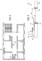
- the ventilation device 102 is placed towards the outlet of the air extraction duct 104 of the building 100. As illustrated in FIG. figure 1b , the ventilation device 102 is located on the roof 105 of the building 100. In other words, the ventilation device 102 is disposed at the top end of the air extraction duct 104. The ventilation device 102 ensures , as previously mentioned, the drawing in the air extraction duct 104 of the fluid to be discharged to the outside of the building 10.
- the figure 1b represents for illustrative purposes such a human occupation space 1 which, for example, is an apartment 103 of a building 100.
- the building may comprise common areas 2, such as a staircase 3 and a landing 4.
- the human occupancy space 1 considered here is therefore delimited on the one hand by the outer walls 5 of the building, the internal walls 6 of the building forming an outer wall of the human occupancy space 1, and the openings carried by the outer or inner walls 6, such as a landing door 7 and windows 8.
- the human occupation space 1 is further delimited by a floor 9 and a ceiling, not visible, for example parallel to the ground.
- Human occupation space 1 is sufficiently large to permit human occupation, it being understood that it is not necessary for the human occupation space 1 to be effectively occupied, permanently or even temporarily, by humans.
- the human occupation space 1 comprises service rooms 10.
- the service rooms are for example a kitchen 10 A, a bathroom 10 B, and a bathroom 10 C.
- the human occupation space also includes 11.
- the living parts 11 are, for example, a stay 11A and one or more chambers 11B.
- intermediate spaces 12 make it possible to circulate between the various pieces 10A, 10B, 10C, 11A. and 11 B.
- the intermediate spaces 12 comprise for example corridors, stairs, landings, ....
- Doors 13 may alternatively allow or restrict access to some of these rooms or spaces.
- FIG. 1b discloses a relatively conventional example of a human occupancy space 1, in which an intermediate space 12, in this case a corridor 12 A, serves most of the rooms of the human occupancy space 1.
- the corridor 12 A is located between the various service rooms 10 and life 11.
- the human occupation space 1 is provided with a ventilation system 14 which will be described in more detail below.
- a ventilation system 14 comprises, on the one hand, air inlets 15 in the human occupancy space 1.
- air inlet systems that are more permeable to air than the walls are included. external 5 or the inner walls 6 to the building. It can for example be natural air intake, such as for example a slot provided at the door 7 to allow its articulation, lateral side level hinges, or a space with the ground. also provide apertures specially arranged for this purpose in and / or at the level of the windows 8.
- the air inlets 15 are passive systems, namely that a flow of air is not generated. air entering at the air inlets 15 actively.
- the ventilation system 14 also comprises air outlets 16.
- the air outlets 16 are systems allowing the air present in the human occupation space 1 to exit from the latter to the outside.
- the exterior designates on the one hand the exterior to the space of human occupation, as defined above delimited by the outer walls 5, the inner walls 6, the floor 12 and the ceiling, but also the exterior of the building itself which incorporates the space of human occupation.
- the building may include, in addition to the human occupation space, for example attics or non-habitable volumes, or other dwellings.
- the air outlets 16 are arranged in the service rooms, such as air outlets 16 A, 16 B, 16 C disposed respectively in the kitchen 10 A, the bathroom 10 B and the bathroom 10 C.
- this implementation is not limiting.
- At least one air inlet 15 and / or at least one air outlet 16 may comprise a ventilation device 17.
- each air inlet 15 and / or each air outlet 16 comprises a ventilation device 17.
- a ventilation device 17 may alternatively be a passive ventilation device, such as an opening or active mouth, such as a device capable of generating a flow of air when it is supplied with energy in the room. Human occupancy space 1.
- Such a device capable of generating an airflow is generally operatively associated with an opening mouth.
- this device capable of generating an air flow is not necessarily disposed in the human occupation space itself, but can be arranged in a duct 104 connecting the human occupation space 1 to outside, especially outside the building (for example on the roof 105, as is the case for the ventilation device 102).
- At least one ventilation device 17 may be a parameterizable ventilation device 18.
- a ventilation device is said to be parameterizable when it can be modified to affect the flow of air in the human occupancy space 1.
- a Typical example of a parameterizable ventilation device 18 is a mouth equipping an air inlet 15 or an air outlet 16 whose cross section can see its modified area, for example by actuation by a user.
- a parameterizable ventilation device 18 can be manually modified by a user, or by a controlled automaton.
- Another example of a parameterizable ventilation device 18 is a fan whose ventilation energy is controlled.
- a parameterizable ventilation device 18 is a ventilation device that can be modified by an occupant of the human occupancy space 1 to influence the flow of air in the human occupancy space 1 during normal use of the ventilation system. This is not the installation of the ventilation system by a qualified professional, when a ventilation device can be configured once and for all, or at least for a long period of time (this device may eventually be reconfigured by a professional equipped periodically but spaced in time from several months or years). Subsequently, we are interested here in an automatically adjustable parameterizable ventilation device 18, without manual action by the occupant, even if such an automatically adjustable parameterizable ventilation device 18 may, if necessary, also be adjustable. by manual action.
- the figure 5 schematically describes an example of a parameterizable ventilation device.
- the ceiling 19 comprises an air outlet 16 provided with a ventilation device 17.
- the ventilation device 17 comprises a mouth 20 defining a through opening in the ceiling 19.
- the mouth 20 has a maximum opening represented by its transverse dimension D.
- the opening of the mouth 20 is adjustable between this maximum opening and a minimum opening which, if necessary, can be of zero opening, or be greater than a threshold predetermined minimum.
- the mouth 20 is shown adjusted with an intermediate opening D i , intermediate between the maximum and minimum openings.
- the opening of the mouth 20 is adjustable according to a setting parameter.
- the setting parameter determines the degree of opening of the mouth between its minimum and maximum openings.
- the setting parameter is a Boolean parameter, each parameter value respectively corresponding to one of the two states that the ventilation device can take (in particular on / off or open / closed or maximum / minimum).
- the adjustment parameter may take at least 3 values, for example an integer or real number of values.
- a control system 21 makes it possible to modify the ventilation device 17 according to the setting parameter.
- the control system 21 comprises for example a movable shutter 22 so as to alternately open or close the through opening in the ceiling connecting the human occupancy space 1 to the outside through the conduit 104 through the air outlet 16.
- the control system 21 also comprises an actuator 23 adapted to move the shutter 22 so as to alternately open or close the through opening in the ceiling, upon receipt of a command.
- the control system 21 also comprises a processor 24 adapted to control the actuator 23 according to an adjustment parameter of the parameterizable ventilation device.
- the processor 24 will control the actuation of the actuator 23 to move the flap 22 relative to the ceiling 19 so as to change the area of the through opening.
- the ventilation system 14 also comprises a control device 25.
- the control device 25 is arranged remote from the ventilation devices 17 described above.
- remote it is understood that the control device 25 is located at a distance from a ventilation device 17, on the scale of manipulation by a human being.
- the control device 25 and the ventilation device 17 may be separate remote devices that can be manipulated independently of one another and that can be fixed independently of one another in the human occupation space. 1.
- the controller 25 has been disposed substantially in a central region of the human occupancy space 1 (seen from above).
- the control device 25 can be disposed between an air inlet 15 of the human occupancy space 1 and an air outlet 16 thereof, in a typical airflow configuration of the space. human occupation 1.
- the control device 25 is shown in the intermediate space 12 constituted by the corridor 12A.
- the controller 25 may be attached to the ceiling 19 or to a vertical wall of the human occupancy space 1, preferably in an upper area thereof.
- the controller 25 is shown in more detail on the figure 2 . It comprises an outer casing 26 forming an enclosure, and capable of being fixed on a structural element adapted to the human occupation space 1, such as a wall or a ceiling. Fixing is done for example by screwing.
- the housing 26 carries a computerized processing system 27, such as a processor.
- the housing 26 also carries an acquisition system 28 integral with the housing 26.
- the acquisition system 28 comprises one or more sensors 29, in particular sensors adapted to detect respectively at least one chemical parameter and / or at least one physical parameter of the ambient air 30 at the housing 26.
- a sensor 29 it is possible for example to provide one and / or the other of a sensor capable of determining a concentration of water 29 A in the ambient air 30, a sensor capable of determining a concentration of carbon monoxide (CO) 29 B in the ambient air, a sensor capable of determining a concentration of organic components 29 C in the ambient air, a sensor capable of determining a concentration of carbon (CO 2 ) in ambient air, a sensor capable of determining a concentration of formaldehyde in the ambient air, a sensor capable of determining a concentration of smoke in the ambient air, a temperature sensor or relative or absolute hygrometry of the ambient air, or other.
- CO carbon monoxide
- Each sensor 29 is connected to the computerized processing system 27 so as to transmit thereto data representative of the respective parameter of the ambient air at the housing 26. That is to say that the sensor 29 is the same. -Even able to determine a parameter of the ambient air from the measurement taken, and transmits the value of this parameter to the computerized processing system 27, ie the computerized processing system 27 itself comprises a computer 43 capable of determining the value of this parameter of the ambient air from the data measured by the sensor 29. If necessary, the computerized processing system 27 can take into account the data measured by several sensors to determine a parameter representative of the ambient air at the housing 26.
- the computerized processing system 27 can use data from several sensors determining different parameters, such as, for example, the concentration of organic components and the temperature, to determine a parameter representative of the ambient air 30 at 30. level of the housing 26 taking into account these several parameters.
- the computerized processing system 27 is adapted to determine at least one adjustment parameter of the autonomously adjustable configurable ventilation opening remote from said at least one detected parameter.
- the parameter detected here, reference is made either to the detected parameter as delivered by one or more sensors, or to a parameter representative of the ambient air, determined by the computerized treatment system from these detected parameters.
- the control device 25 comprises a memory 31 storing a law making it possible to determine a value of a setting parameter of the parameterizable ventilator that can be adjusted remotely from detected parameters, and the computerized treatment system 27 is configured to extract from the memory 31 a setting parameter of the programmable remote control vent valve that is automatically adjustable from the detected parameters.
- the memory 31 can store a table 32 having, at its input, different values for parameters representative of the ambient air, in particular of the concentration of carbon dioxide (X 1 ,..., X 2 ,. in smoke F (Y 1 , ..., Y 2 , ...), and the temperature T (Z 1 , ... Z n ) and associating, for each trinomial of detected values representative of the ambient air (X i , Y j , Z k ) an IJK value A for a parameter P1 of a configurable ventilation port adjustable in a remote automated manner, and a value B IJK for a parameter P2 of a parametrically adjustable ventilation port in a remote automated manner .
- the computerized processing system 27 can determine a setting parameter of the parameterizable ventilation opening, or two parameters of the same parametric ventilation opening, or more, or one or more parameters of several different adjustable ventilation vents.
- the law stored in the memory 31 may also take into account other parameters, such as different predefined configurations.
- the computerized processing system 27 is adapted to modify the setting of the parameterizable ventilation opening from a modification of a value detected for a representative parameter ambient air at the housing, without making an explicit determination of this setting parameter. For example, if a sensor detects an increase in the carbon dioxide concentration at the ambient air level of the housing 26, above a predetermined threshold, the computerized treatment system will determine that it is necessary to increase the ventilation rate.
- the setting parameter of the remote fan mouth may be chosen from ⁇ -1; 0; 1 ⁇ , where 0 is "do not change the remote fan", -1 is "decrease ventilation in the remote fan", and 1 is "increase ventilation in the remote fan” .
- the control device 25 also comprises a communication device 33.
- the communication device 33 is carried by the housing 26 and is adapted to transmit, in the direction of the parameterizable ventilation opening, the adjustment parameter determined by the computerized treatment system. 27. Any type of adapted communication device, in particular wired or wireless, is used.
- the communication device 33 will be described in more detail below in relation to the parameterizable ventilation opening.
- the figure 2 also represents the parameterizable ventilation opening 18 as has already been partially described above in relation to the figure 5 .
- the parameterizable ventilation opening comprises a computerized processing system 34 and a communication device 35.
- the communication device 35 of the parameterizable ventilation opening 18 is adapted to receive the adjustment parameter from the control device 25.
- communication 35 of the programmable ventilation opening 18 and the communication device 33 of the control device 25 are paired together to form a communication system to be able to communicate information between them, in particular in the direction from the control device 25 to the parameterizable ventilation opening 18.
- the communication between these two devices communication is for example made wireless, for example by radio waves, or wired. In the latter case, a wire extends between the control device 25 and the parameterizable ventilation opening 18 to carry the required information between the two devices.
- the communication device 33 of the control device 25 is adapted to communicate to each separate parameterizable ventilation port 18 the parameter setting of its own.
- a terminal block of the control device 25 comprises a plurality of terminals each connected to one of the parameterizable ventilation openings 18, and an adjustment parameter, if necessary separate, is assigned to each terminal.
- the computerized processing system 34 of the parameterizable ventilation opening 18 is adapted to process information received by the communication device 35, and to modify the ventilation opening so as to modify the flow of air from this setting parameter .
- the actuator 23 also shown on the figure 5 , is represented on the figure 2 .
- the actuator 23 is adapted to receive a command from the computerized processing system 34, taking into account the adjustment parameter, and to modify the parameterizable ventilation opening 18 so as to modify the flow of air passing through it. this.
- the computerized processing system 34 and the actuator 23 together form a control system 44 of the parameterizable ventilation opening 18.
- the parameterized ventilation system could also take into account, in order to determine the parameter of adjustment of the parameterizable ventilation opening (s) 18, another parameter, or additional parameter, for example representative of the external conditions to the human occupation space 1.
- additional parameter may for example include the temperature outside the building in which the human occupancy space 1 is located, or the wind speed at an outgoing air exhaust port.
- human occupation space 1 a temporal parameter (day / night, week / weekend) or social parameter (presence / absence, day of activity / non-working day, ...) or other.
- the parameterized ventilation system could also take into account, in order to determine the parameter of adjustment of the parameterizable ventilation opening 18, a similar additional parameter of the parameters already detected by the control device 25, and at another location of the 1.
- the additional parameter can thus for example be a local concentration in the ambient air in water, carbon monoxide, carbon dioxide, organic components, smoke, or other.
- a remote system 36 disposed either in the human occupation space 1 or outside and adapted to determine a local parameter and to communicate this parameter to the control device 25.
- the remote system 36 may comprise a remote acquisition system 37 which comprises a sensor, for example of the type described above, carried by a housing 38.
- the housing 38 is remote from the housing 26.
- the housing 38 also carries a communication device 39 adapted to communicate with a communication device 40 adapted from the control device 25.
- the remote system 36 may comprise a system computerized processing 41 adapted to process and format the data from the sensor of the remote acquisition system, and to control the outgoing communication device 39.
- the communication devices 33, 40 of the control device 25 may, where appropriate, be grouped into a single communication device, comprising a sufficient number of terminals in the wired version, and / or a sufficient number of addresses in the wired version. the wireless version.
- the computerized processing system 27 will be adapted to take into account the information from the remote system 36 to determine the adjustment parameters of the parameterizable ventilation device 18.
- the control device 25 is installed, for example on the ceiling of the human occupancy space 1.
- the control device is installed remote from the ventilation devices, in particular adjustable ventilation devices.
- Power is supplied to the control device 25, in particular so that the acquisition system 28 and the computerized processing system 27 can operate.
- an internal battery is used, where the control device 25 is connected to the mains.
- the communication system is installed, so that the control device 25 can communicate with the adjustable ventilation devices, either wired (connection) or wireless (computer configuration).
- the control device 25 is configured, for example to take into account the particularities of the human occupation space 1 to be ventilated.
- This configuration may include, for the professional in charge of the installation, the selection of one or more parameters for the implementation of the ventilation system.
- the memory 31 includes a plurality of preset laws
- the controller 25 includes a means for selecting one of these laws.
- the means for selecting may be a computer or physical means, such as a switch made on the housing 26.
- the switch may have positions corresponding to modes relating to the type of human occupancy space 1, for example individual dwelling / collective dwellings / office, environmental modes, eg hot / cold region, or other.
- the means of selection can also make it possible to inform the volume, and the location of the various components of the parameterizable ventilation system and the human occupancy space 1.
- control device implements a method for controlling a remote parameterizable ventilation opening so as to regulate the flow of air in the human occupancy space 1.
- the communication device 33 communicates and transmits in the direction of the adjustable ventilation opening the setting parameter.
- the adjustable vent opening 18 receives the setting parameter, and is modified to change the airflow at the human occupancy space 1. For example, if the controller 25 controls to increase the level of ventilation in the human occupation space, for example due to the increase in the concentration of carbon monoxide detected in the ambient air at the housing 26, the opening of the mouths at the air outlets 16 and / or air inlets 15 can be increased automatically.
- control device 25 If necessary, during a regular maintenance operation, it is possible to modify the law implemented by the control device 25. For example, this modification can be made following a change of regulation relating to thresholds imposed for the concentrations some of the chemical species in the ambient air.
- control device 14 may preferably be arranged at a place specially adapted for determining the characteristics of the ambient air representative of the ambient air in the human occupancy space 1.
- the device 14 can be placed relatively in the center of the housing, seen from above, in a location of strong passage, or in a particular room of the human occupancy space 1.
- the figure 4 represents an alternative embodiment of the system according to the figure 1 b.
- the flow of air entering directly at the inlet of air 15 can be controlled.
- a rotational speed of the air blower of the air blowing system 42 may be controlled.
- the user interface 45 comprises a housing 46 that can be installed in a manner accessible to a user of the housing (for example, fixed to the wall at eye level of an adult human, in the entrance of the space of human occupation 1).
- the housing 46 carries a display means 47, such as a screen, for displaying information.
- the information is for example the current operating mode of one or more configurable ventilation opening (s), the applied law, one or more parameters of the ambient air, any information stored in the memory 31.
- the housing 46 also carries a communication system 48 adapted to communicate with a corresponding communication system 49 of the control device 25 (where appropriate grouped with the other communication systems thereof). For example, a wireless or wired system is used.
- the user interface 45 also comprises a processor 50 which controls the various components of the user interface 45, such as the display means 47, the communication system 48, to be able to display the necessary information stored in the memory 31.
- user interface 45 also includes a keyboard 51 (or a touch screen of screen 47) allowing the user to communicate with the customizable ventilation system.
- the keyboard 51 could for example be used by the user to navigate through menus making it possible to choose the display provided on the display means 47.
- the keyboard 51 could allow the user to influence the operation of the control device.
- the keyboard 51 could for example allow the user to choose the law to be applied among the predetermined laws stored in the memory 31.
- the user interface 45 may be used by the installer himself for the configuration of the ventilation system.
- the user interface 45 may allow several levels of authorization, between a blocked level for a person without the necessary authorization, a user level for a person with a "user" authorization (including one or more occupants space of human occupation can choose a law to be applied among several laws), an installer level for a person having an "installer” authorization (notably that can configure the laws or modify them to adapt to changes of regulation).
- These different levels of authorization are defined by passwords and / or hardware interfaces (specific key for example).
- the present invention may be of particular interest in the field of collective housing ventilation. Indeed, it allows to modulate the ventilation of different premises associated with a common fan via ducts 104.
- the common fan 102 may be, if necessary, adjusted or adjustable to define a general strategy of ventilation housing associated with it, on criteria, for example climatic, and intended for example to optimize the energy consumption of the common fan 102.
- the adjustable mouths can modulate at the level of each housing this general strategy to take into account the specificities of each housing , thus making it possible to optimize the energy savings achieved on the extracted air flow rates with respect to the needs of the current pollutant concentration levels to ensure good indoor air quality.
- different units associated with the same fan can meet different ventilation requirements at each given moment. For example, some may be commercial or tertiary business areas (schools, offices, ...) and other dwellings, with consequently different pollutant levels at a time of day, different temperatures, etc. ...
Landscapes
- Engineering & Computer Science (AREA)
- Chemical & Material Sciences (AREA)
- Combustion & Propulsion (AREA)
- Mechanical Engineering (AREA)
- General Engineering & Computer Science (AREA)
- Physics & Mathematics (AREA)
- Signal Processing (AREA)
- Fluid Mechanics (AREA)
- Fuzzy Systems (AREA)
- Mathematical Physics (AREA)
- Ventilation (AREA)
- Air Conditioning Control Device (AREA)
Applications Claiming Priority (1)
| Application Number | Priority Date | Filing Date | Title |
|---|---|---|---|
| FR1356348A FR3007827B1 (fr) | 2013-06-28 | 2013-06-28 | Dispositif de commande d'au moins un dispositif de ventilation parametrable. |
Publications (3)
| Publication Number | Publication Date |
|---|---|
| EP2853823A2 true EP2853823A2 (de) | 2015-04-01 |
| EP2853823A3 EP2853823A3 (de) | 2015-11-25 |
| EP2853823B1 EP2853823B1 (de) | 2021-03-10 |
Family
ID=49237379
Family Applications (1)
| Application Number | Title | Priority Date | Filing Date |
|---|---|---|---|
| EP14174895.4A Active EP2853823B1 (de) | 2013-06-28 | 2014-06-30 | Parametrierbares Belüftungssystem |
Country Status (4)
| Country | Link |
|---|---|
| EP (1) | EP2853823B1 (de) |
| ES (1) | ES2872402T3 (de) |
| FR (1) | FR3007827B1 (de) |
| PT (1) | PT2853823T (de) |
Cited By (1)
| Publication number | Priority date | Publication date | Assignee | Title |
|---|---|---|---|---|
| EP4153919B1 (de) | 2020-05-19 | 2024-02-14 | Renson Ventilation NV | Verfahren und vorrichtung zum konfigurieren eines belüftungssystems |
Families Citing this family (2)
| Publication number | Priority date | Publication date | Assignee | Title |
|---|---|---|---|---|
| FR3124583B1 (fr) * | 2021-06-24 | 2023-10-27 | Labo Aai | Système de traitement d’air avec régulation par capteur de qualité d’air |
| FR3166689A1 (fr) * | 2024-09-24 | 2026-03-27 | Anjos Ventilation | Station de mesure, accessoire de ventilation, installation de ventilation et méthode de pilotage associés |
Citations (1)
| Publication number | Priority date | Publication date | Assignee | Title |
|---|---|---|---|---|
| WO2004076932A2 (fr) | 2003-02-26 | 2004-09-10 | Astato | Procede de reglage d’un ventilateur d’un systeme de ventilation d’un batiment |
Family Cites Families (7)
| Publication number | Priority date | Publication date | Assignee | Title |
|---|---|---|---|---|
| US5215498A (en) * | 1991-03-04 | 1993-06-01 | Gaztech International Corporation | Ventilation controller |
| CA2177941A1 (en) * | 1996-05-31 | 1997-12-01 | Francois Routhier | Fail-safe networked control system for ventilation units |
| FR2824358B1 (fr) * | 2001-05-02 | 2005-08-26 | Archimedes Sarl | Procede de controle automatise du niveau d'apport d'eclairage naturel et/ou d'energie calorifique dans une piece par au moins une de ses ouvertures et/ou de controle de la qualite de l'air |
| WO2004022207A1 (en) * | 2002-09-03 | 2004-03-18 | Acker Phillip F | Ventilation system with humidity responsive ventilation controller |
| US20050277381A1 (en) * | 2004-06-15 | 2005-12-15 | Chinmoy Banerjee | System to control environmental conditions in a living space |
| US20100078494A1 (en) * | 2008-10-01 | 2010-04-01 | Marco Mularoni | Humidity-activated ventilation system switch |
| US8364318B2 (en) * | 2010-04-21 | 2013-01-29 | Honeywell International Inc. | Demand control ventilation with fan speed control |
-
2013
- 2013-06-28 FR FR1356348A patent/FR3007827B1/fr active Active
-
2014
- 2014-06-30 PT PT141748954T patent/PT2853823T/pt unknown
- 2014-06-30 ES ES14174895T patent/ES2872402T3/es active Active
- 2014-06-30 EP EP14174895.4A patent/EP2853823B1/de active Active
Patent Citations (1)
| Publication number | Priority date | Publication date | Assignee | Title |
|---|---|---|---|---|
| WO2004076932A2 (fr) | 2003-02-26 | 2004-09-10 | Astato | Procede de reglage d’un ventilateur d’un systeme de ventilation d’un batiment |
Cited By (1)
| Publication number | Priority date | Publication date | Assignee | Title |
|---|---|---|---|---|
| EP4153919B1 (de) | 2020-05-19 | 2024-02-14 | Renson Ventilation NV | Verfahren und vorrichtung zum konfigurieren eines belüftungssystems |
Also Published As
| Publication number | Publication date |
|---|---|
| PT2853823T (pt) | 2021-06-09 |
| ES2872402T3 (es) | 2021-11-02 |
| EP2853823B1 (de) | 2021-03-10 |
| FR3007827A1 (fr) | 2015-01-02 |
| EP2853823A3 (de) | 2015-11-25 |
| FR3007827B1 (fr) | 2019-05-24 |
Similar Documents
| Publication | Publication Date | Title |
|---|---|---|
| US11733101B2 (en) | Smart wall switch controller | |
| US10001288B1 (en) | Smart fan and ventilation system and method | |
| US10859985B2 (en) | Device and method for controlling a window or window shading device based on measurements and a setpoint | |
| US9960929B2 (en) | Environmental sensing with a doorbell at a smart-home | |
| US20150154850A1 (en) | Leveraging neighborhood to handle potential visitor at a smart-home | |
| US20150109104A1 (en) | Smart invitation handling at a smart-home | |
| US20150116107A1 (en) | Initially detecting a visitor at a smart-home | |
| EP3477215B1 (de) | Steuerungssystem von belüftungseinheiten | |
| WO2016109839A1 (en) | Handling visitor interaction at a smart-home in a do not disturb mode | |
| EP2853823B1 (de) | Parametrierbares Belüftungssystem | |
| EP2781976B1 (de) | Verfahren und Einheit zum Abschätzen und zur Optimierung des Energieverbrauchs zum Heizen und/oder Kühlen mit der Klimaanlage | |
| EP2891846B1 (de) | Steuerungsverfahren eines Belüftungssystems mit einfachem Luftfluss | |
| FR3146339A1 (fr) | Procédé de régulation d’un réseau de ventilation d’un bâtiment | |
| CA2962504A1 (fr) | Systeme climatique connecte | |
| EP2998657B1 (de) | Belüftungssystem eines gebäudes und steuerbares mittel zum unterteiltem lufteinlass | |
| WO1999043992A1 (fr) | Dispositif integre, prefabrique et modulaire, de chauffage et de ventilation d'un local de batiment | |
| FR2966227A1 (fr) | Installation de ventilation mecanique par insufflation hygroregulee et procede associe | |
| EP1490634B1 (de) | Heizvorrichtung und/oder klimaanlage | |
| EP3237810B1 (de) | System zur steuerung einer belüftungsanlage, belüftungsanlage mit solch einem steuerungssystem und bereich | |
| EP4545870A1 (de) | Verfahren zur konfiguration eines luftaufbereitungskraftwerks | |
| FR2966226A1 (fr) | Installation de ventilation mecanique par insufflation hygroregulee et procede associe | |
| WO2003076849A1 (fr) | Installation de climatisation | |
| FR3018901A1 (fr) | Systeme de climatisation naturelle a ventilation mecanique controlee | |
| EP4715280A1 (de) | Messstation, lüftungszubehör, lüftungsanlage und verfahren zur steuerung derselben |
Legal Events
| Date | Code | Title | Description |
|---|---|---|---|
| PUAI | Public reference made under article 153(3) epc to a published international application that has entered the european phase |
Free format text: ORIGINAL CODE: 0009012 |
|
| 17P | Request for examination filed |
Effective date: 20140630 |
|
| AK | Designated contracting states |
Kind code of ref document: A2 Designated state(s): AL AT BE BG CH CY CZ DE DK EE ES FI FR GB GR HR HU IE IS IT LI LT LU LV MC MK MT NL NO PL PT RO RS SE SI SK SM TR |
|
| AX | Request for extension of the european patent |
Extension state: BA ME |
|
| PUAL | Search report despatched |
Free format text: ORIGINAL CODE: 0009013 |
|
| AK | Designated contracting states |
Kind code of ref document: A3 Designated state(s): AL AT BE BG CH CY CZ DE DK EE ES FI FR GB GR HR HU IE IS IT LI LT LU LV MC MK MT NL NO PL PT RO RS SE SI SK SM TR |
|
| AX | Request for extension of the european patent |
Extension state: BA ME |
|
| RIC1 | Information provided on ipc code assigned before grant |
Ipc: F24F 1/00 20110101AFI20151016BHEP Ipc: F24F 11/00 20060101ALI20151016BHEP |
|
| 111L | Licence recorded |
Designated state(s): AL AT BE BG CH CY CZ DE DK EE ES FI FR GB GR HR HU IE IS IT LT LU LV MC MK MT NL NO PL PT RO RS SE SI SK SM TR Free format text: EXCLUSIVE LICENSE Name of requester: ASTATO, FR Effective date: 20160203 |
|
| R17P | Request for examination filed (corrected) |
Effective date: 20160525 |
|
| RBV | Designated contracting states (corrected) |
Designated state(s): AL AT BE BG CH CY CZ DE DK EE ES FI FR GB GR HR HU IE IS IT LI LT LU LV MC MK MT NL NO PL PT RO RS SE SI SK SM TR |
|
| STAA | Information on the status of an ep patent application or granted ep patent |
Free format text: STATUS: EXAMINATION IS IN PROGRESS |
|
| 17Q | First examination report despatched |
Effective date: 20180912 |
|
| GRAP | Despatch of communication of intention to grant a patent |
Free format text: ORIGINAL CODE: EPIDOSNIGR1 |
|
| STAA | Information on the status of an ep patent application or granted ep patent |
Free format text: STATUS: GRANT OF PATENT IS INTENDED |
|
| INTG | Intention to grant announced |
Effective date: 20201001 |
|
| GRAS | Grant fee paid |
Free format text: ORIGINAL CODE: EPIDOSNIGR3 |
|
| GRAA | (expected) grant |
Free format text: ORIGINAL CODE: 0009210 |
|
| STAA | Information on the status of an ep patent application or granted ep patent |
Free format text: STATUS: THE PATENT HAS BEEN GRANTED |
|
| 111L | Licence recorded |
Designated state(s): AL AT BE BG CH CY CZ DE DK EE ES FI FR GB GR HR HU IE IS IT LT LU LV MC MK MT NL NO PL PT RO RS SE SI SK SM TR Free format text: EXCLUSIVE LICENSE Name of requester: ASTATO, FR Effective date: 20160203 |
|
| AK | Designated contracting states |
Kind code of ref document: B1 Designated state(s): AL AT BE BG CH CY CZ DE DK EE ES FI FR GB GR HR HU IE IS IT LI LT LU LV MC MK MT NL NO PL PT RO RS SE SI SK SM TR |
|
| REG | Reference to a national code |
Ref country code: GB Ref legal event code: FG4D Free format text: NOT ENGLISH |
|
| REG | Reference to a national code |
Ref country code: CH Ref legal event code: EP Ref country code: AT Ref legal event code: REF Ref document number: 1370228 Country of ref document: AT Kind code of ref document: T Effective date: 20210315 |
|
| REG | Reference to a national code |
Ref country code: IE Ref legal event code: FG4D Free format text: LANGUAGE OF EP DOCUMENT: FRENCH |
|
| REG | Reference to a national code |
Ref country code: DE Ref legal event code: R096 Ref document number: 602014075503 Country of ref document: DE |
|
| REG | Reference to a national code |
Ref country code: NL Ref legal event code: FP Ref country code: PT Ref legal event code: SC4A Ref document number: 2853823 Country of ref document: PT Date of ref document: 20210609 Kind code of ref document: T Free format text: AVAILABILITY OF NATIONAL TRANSLATION Effective date: 20210604 |
|
| REG | Reference to a national code |
Ref country code: LT Ref legal event code: MG9D |
|
| PG25 | Lapsed in a contracting state [announced via postgrant information from national office to epo] |
Ref country code: NO Free format text: LAPSE BECAUSE OF FAILURE TO SUBMIT A TRANSLATION OF THE DESCRIPTION OR TO PAY THE FEE WITHIN THE PRESCRIBED TIME-LIMIT Effective date: 20210610 Ref country code: BG Free format text: LAPSE BECAUSE OF FAILURE TO SUBMIT A TRANSLATION OF THE DESCRIPTION OR TO PAY THE FEE WITHIN THE PRESCRIBED TIME-LIMIT Effective date: 20210610 Ref country code: LT Free format text: LAPSE BECAUSE OF FAILURE TO SUBMIT A TRANSLATION OF THE DESCRIPTION OR TO PAY THE FEE WITHIN THE PRESCRIBED TIME-LIMIT Effective date: 20210310 Ref country code: HR Free format text: LAPSE BECAUSE OF FAILURE TO SUBMIT A TRANSLATION OF THE DESCRIPTION OR TO PAY THE FEE WITHIN THE PRESCRIBED TIME-LIMIT Effective date: 20210310 Ref country code: FI Free format text: LAPSE BECAUSE OF FAILURE TO SUBMIT A TRANSLATION OF THE DESCRIPTION OR TO PAY THE FEE WITHIN THE PRESCRIBED TIME-LIMIT Effective date: 20210310 Ref country code: GR Free format text: LAPSE BECAUSE OF FAILURE TO SUBMIT A TRANSLATION OF THE DESCRIPTION OR TO PAY THE FEE WITHIN THE PRESCRIBED TIME-LIMIT Effective date: 20210611 |
|
| REG | Reference to a national code |
Ref country code: AT Ref legal event code: MK05 Ref document number: 1370228 Country of ref document: AT Kind code of ref document: T Effective date: 20210310 |
|
| PG25 | Lapsed in a contracting state [announced via postgrant information from national office to epo] |
Ref country code: SE Free format text: LAPSE BECAUSE OF FAILURE TO SUBMIT A TRANSLATION OF THE DESCRIPTION OR TO PAY THE FEE WITHIN THE PRESCRIBED TIME-LIMIT Effective date: 20210310 Ref country code: RS Free format text: LAPSE BECAUSE OF FAILURE TO SUBMIT A TRANSLATION OF THE DESCRIPTION OR TO PAY THE FEE WITHIN THE PRESCRIBED TIME-LIMIT Effective date: 20210310 Ref country code: LV Free format text: LAPSE BECAUSE OF FAILURE TO SUBMIT A TRANSLATION OF THE DESCRIPTION OR TO PAY THE FEE WITHIN THE PRESCRIBED TIME-LIMIT Effective date: 20210310 |
|
| PG25 | Lapsed in a contracting state [announced via postgrant information from national office to epo] |
Ref country code: EE Free format text: LAPSE BECAUSE OF FAILURE TO SUBMIT A TRANSLATION OF THE DESCRIPTION OR TO PAY THE FEE WITHIN THE PRESCRIBED TIME-LIMIT Effective date: 20210310 Ref country code: CZ Free format text: LAPSE BECAUSE OF FAILURE TO SUBMIT A TRANSLATION OF THE DESCRIPTION OR TO PAY THE FEE WITHIN THE PRESCRIBED TIME-LIMIT Effective date: 20210310 Ref country code: AT Free format text: LAPSE BECAUSE OF FAILURE TO SUBMIT A TRANSLATION OF THE DESCRIPTION OR TO PAY THE FEE WITHIN THE PRESCRIBED TIME-LIMIT Effective date: 20210310 Ref country code: SM Free format text: LAPSE BECAUSE OF FAILURE TO SUBMIT A TRANSLATION OF THE DESCRIPTION OR TO PAY THE FEE WITHIN THE PRESCRIBED TIME-LIMIT Effective date: 20210310 |
|
| REG | Reference to a national code |
Ref country code: ES Ref legal event code: FG2A Ref document number: 2872402 Country of ref document: ES Kind code of ref document: T3 Effective date: 20211102 |
|
| PG25 | Lapsed in a contracting state [announced via postgrant information from national office to epo] |
Ref country code: PL Free format text: LAPSE BECAUSE OF FAILURE TO SUBMIT A TRANSLATION OF THE DESCRIPTION OR TO PAY THE FEE WITHIN THE PRESCRIBED TIME-LIMIT Effective date: 20210310 Ref country code: SK Free format text: LAPSE BECAUSE OF FAILURE TO SUBMIT A TRANSLATION OF THE DESCRIPTION OR TO PAY THE FEE WITHIN THE PRESCRIBED TIME-LIMIT Effective date: 20210310 Ref country code: RO Free format text: LAPSE BECAUSE OF FAILURE TO SUBMIT A TRANSLATION OF THE DESCRIPTION OR TO PAY THE FEE WITHIN THE PRESCRIBED TIME-LIMIT Effective date: 20210310 Ref country code: IS Free format text: LAPSE BECAUSE OF FAILURE TO SUBMIT A TRANSLATION OF THE DESCRIPTION OR TO PAY THE FEE WITHIN THE PRESCRIBED TIME-LIMIT Effective date: 20210710 |
|
| REG | Reference to a national code |
Ref country code: DE Ref legal event code: R097 Ref document number: 602014075503 Country of ref document: DE |
|
| PLBE | No opposition filed within time limit |
Free format text: ORIGINAL CODE: 0009261 |
|
| STAA | Information on the status of an ep patent application or granted ep patent |
Free format text: STATUS: NO OPPOSITION FILED WITHIN TIME LIMIT |
|
| PG25 | Lapsed in a contracting state [announced via postgrant information from national office to epo] |
Ref country code: DK Free format text: LAPSE BECAUSE OF FAILURE TO SUBMIT A TRANSLATION OF THE DESCRIPTION OR TO PAY THE FEE WITHIN THE PRESCRIBED TIME-LIMIT Effective date: 20210310 Ref country code: AL Free format text: LAPSE BECAUSE OF FAILURE TO SUBMIT A TRANSLATION OF THE DESCRIPTION OR TO PAY THE FEE WITHIN THE PRESCRIBED TIME-LIMIT Effective date: 20210310 Ref country code: MC Free format text: LAPSE BECAUSE OF FAILURE TO SUBMIT A TRANSLATION OF THE DESCRIPTION OR TO PAY THE FEE WITHIN THE PRESCRIBED TIME-LIMIT Effective date: 20210310 |
|
| 26N | No opposition filed |
Effective date: 20211213 |
|
| PG25 | Lapsed in a contracting state [announced via postgrant information from national office to epo] |
Ref country code: SI Free format text: LAPSE BECAUSE OF FAILURE TO SUBMIT A TRANSLATION OF THE DESCRIPTION OR TO PAY THE FEE WITHIN THE PRESCRIBED TIME-LIMIT Effective date: 20210310 |
|
| PG25 | Lapsed in a contracting state [announced via postgrant information from national office to epo] |
Ref country code: IE Free format text: LAPSE BECAUSE OF NON-PAYMENT OF DUE FEES Effective date: 20210630 |
|
| PG25 | Lapsed in a contracting state [announced via postgrant information from national office to epo] |
Ref country code: IS Free format text: LAPSE BECAUSE OF FAILURE TO SUBMIT A TRANSLATION OF THE DESCRIPTION OR TO PAY THE FEE WITHIN THE PRESCRIBED TIME-LIMIT Effective date: 20210710 |
|
| PG25 | Lapsed in a contracting state [announced via postgrant information from national office to epo] |
Ref country code: HU Free format text: LAPSE BECAUSE OF FAILURE TO SUBMIT A TRANSLATION OF THE DESCRIPTION OR TO PAY THE FEE WITHIN THE PRESCRIBED TIME-LIMIT; INVALID AB INITIO Effective date: 20140630 |
|
| PG25 | Lapsed in a contracting state [announced via postgrant information from national office to epo] |
Ref country code: CY Free format text: LAPSE BECAUSE OF FAILURE TO SUBMIT A TRANSLATION OF THE DESCRIPTION OR TO PAY THE FEE WITHIN THE PRESCRIBED TIME-LIMIT Effective date: 20210310 |
|
| P01 | Opt-out of the competence of the unified patent court (upc) registered |
Effective date: 20230601 |
|
| PG25 | Lapsed in a contracting state [announced via postgrant information from national office to epo] |
Ref country code: MK Free format text: LAPSE BECAUSE OF FAILURE TO SUBMIT A TRANSLATION OF THE DESCRIPTION OR TO PAY THE FEE WITHIN THE PRESCRIBED TIME-LIMIT Effective date: 20210310 |
|
| PGFP | Annual fee paid to national office [announced via postgrant information from national office to epo] |
Ref country code: GB Payment date: 20240626 Year of fee payment: 11 |
|
| PG25 | Lapsed in a contracting state [announced via postgrant information from national office to epo] |
Ref country code: MT Free format text: LAPSE BECAUSE OF FAILURE TO SUBMIT A TRANSLATION OF THE DESCRIPTION OR TO PAY THE FEE WITHIN THE PRESCRIBED TIME-LIMIT Effective date: 20210310 |
|
| PGFP | Annual fee paid to national office [announced via postgrant information from national office to epo] |
Ref country code: ES Payment date: 20240705 Year of fee payment: 11 Ref country code: CH Payment date: 20240704 Year of fee payment: 11 |
|
| PGFP | Annual fee paid to national office [announced via postgrant information from national office to epo] |
Ref country code: NL Payment date: 20250528 Year of fee payment: 12 |
|
| PGFP | Annual fee paid to national office [announced via postgrant information from national office to epo] |
Ref country code: DE Payment date: 20250617 Year of fee payment: 12 |
|
| PGFP | Annual fee paid to national office [announced via postgrant information from national office to epo] |
Ref country code: LU Payment date: 20250528 Year of fee payment: 12 Ref country code: BE Payment date: 20250625 Year of fee payment: 12 |
|
| PGFP | Annual fee paid to national office [announced via postgrant information from national office to epo] |
Ref country code: PT Payment date: 20250523 Year of fee payment: 12 |
|
| PGFP | Annual fee paid to national office [announced via postgrant information from national office to epo] |
Ref country code: FR Payment date: 20250515 Year of fee payment: 12 |
|
| PGFP | Annual fee paid to national office [announced via postgrant information from national office to epo] |
Ref country code: IT Payment date: 20250609 Year of fee payment: 12 |
|
| PG25 | Lapsed in a contracting state [announced via postgrant information from national office to epo] |
Ref country code: TR Free format text: LAPSE BECAUSE OF FAILURE TO SUBMIT A TRANSLATION OF THE DESCRIPTION OR TO PAY THE FEE WITHIN THE PRESCRIBED TIME-LIMIT Effective date: 20210310 |
|
| REG | Reference to a national code |
Ref country code: CH Ref legal event code: H13 Free format text: ST27 STATUS EVENT CODE: U-0-0-H10-H13 (AS PROVIDED BY THE NATIONAL OFFICE) Effective date: 20260127 |
|
| GBPC | Gb: european patent ceased through non-payment of renewal fee |
Effective date: 20250630 |
|
| PG25 | Lapsed in a contracting state [announced via postgrant information from national office to epo] |
Ref country code: GB Free format text: LAPSE BECAUSE OF NON-PAYMENT OF DUE FEES Effective date: 20250630 |
|
| PG25 | Lapsed in a contracting state [announced via postgrant information from national office to epo] |
Ref country code: CH Free format text: LAPSE BECAUSE OF NON-PAYMENT OF DUE FEES Effective date: 20250630 |