EP2853769A1 - Véhicule automobile agence pour reduire des excitations vibratoires d'un compresseur de climatisation - Google Patents
Véhicule automobile agence pour reduire des excitations vibratoires d'un compresseur de climatisation Download PDFInfo
- Publication number
- EP2853769A1 EP2853769A1 EP14184121.3A EP14184121A EP2853769A1 EP 2853769 A1 EP2853769 A1 EP 2853769A1 EP 14184121 A EP14184121 A EP 14184121A EP 2853769 A1 EP2853769 A1 EP 2853769A1
- Authority
- EP
- European Patent Office
- Prior art keywords
- compressor
- motor vehicle
- pulley
- combustion engine
- gear ratio
- Prior art date
- Legal status (The legal status is an assumption and is not a legal conclusion. Google has not performed a legal analysis and makes no representation as to the accuracy of the status listed.)
- Withdrawn
Links
Images
Classifications
-
- B—PERFORMING OPERATIONS; TRANSPORTING
- B60—VEHICLES IN GENERAL
- B60W—CONJOINT CONTROL OF VEHICLE SUB-UNITS OF DIFFERENT TYPE OR DIFFERENT FUNCTION; CONTROL SYSTEMS SPECIALLY ADAPTED FOR HYBRID VEHICLES; ROAD VEHICLE DRIVE CONTROL SYSTEMS FOR PURPOSES NOT RELATED TO THE CONTROL OF A PARTICULAR SUB-UNIT
- B60W10/00—Conjoint control of vehicle sub-units of different type or different function
- B60W10/30—Conjoint control of vehicle sub-units of different type or different function including control of auxiliary equipment, e.g. air-conditioning compressors or oil pumps
-
- B—PERFORMING OPERATIONS; TRANSPORTING
- B60—VEHICLES IN GENERAL
- B60H—ARRANGEMENTS OF HEATING, COOLING, VENTILATING OR OTHER AIR-TREATING DEVICES SPECIALLY ADAPTED FOR PASSENGER OR GOODS SPACES OF VEHICLES
- B60H1/00—Heating, cooling or ventilating devices
- B60H1/32—Cooling devices
- B60H1/3204—Cooling devices using compression
- B60H1/3205—Control means therefor
- B60H1/3208—Vehicle drive related control of the compressor drive means, e.g. for fuel saving purposes
-
- B—PERFORMING OPERATIONS; TRANSPORTING
- B60—VEHICLES IN GENERAL
- B60W—CONJOINT CONTROL OF VEHICLE SUB-UNITS OF DIFFERENT TYPE OR DIFFERENT FUNCTION; CONTROL SYSTEMS SPECIALLY ADAPTED FOR HYBRID VEHICLES; ROAD VEHICLE DRIVE CONTROL SYSTEMS FOR PURPOSES NOT RELATED TO THE CONTROL OF A PARTICULAR SUB-UNIT
- B60W10/00—Conjoint control of vehicle sub-units of different type or different function
- B60W10/04—Conjoint control of vehicle sub-units of different type or different function including control of propulsion units
- B60W10/06—Conjoint control of vehicle sub-units of different type or different function including control of propulsion units including control of combustion engines
-
- F—MECHANICAL ENGINEERING; LIGHTING; HEATING; WEAPONS; BLASTING
- F16—ENGINEERING ELEMENTS AND UNITS; GENERAL MEASURES FOR PRODUCING AND MAINTAINING EFFECTIVE FUNCTIONING OF MACHINES OR INSTALLATIONS; THERMAL INSULATION IN GENERAL
- F16H—GEARING
- F16H7/00—Gearings for conveying rotary motion by endless flexible members
- F16H7/02—Gearings for conveying rotary motion by endless flexible members with belts; with V-belts
-
- B—PERFORMING OPERATIONS; TRANSPORTING
- B60—VEHICLES IN GENERAL
- B60W—CONJOINT CONTROL OF VEHICLE SUB-UNITS OF DIFFERENT TYPE OR DIFFERENT FUNCTION; CONTROL SYSTEMS SPECIALLY ADAPTED FOR HYBRID VEHICLES; ROAD VEHICLE DRIVE CONTROL SYSTEMS FOR PURPOSES NOT RELATED TO THE CONTROL OF A PARTICULAR SUB-UNIT
- B60W30/00—Purposes of road vehicle drive control systems not related to the control of a particular sub-unit, e.g. of systems using conjoint control of vehicle sub-units
- B60W30/18—Propelling the vehicle
- B60W30/20—Reducing vibrations in the driveline
- B60W2030/206—Reducing vibrations in the driveline related or induced by the engine
-
- F—MECHANICAL ENGINEERING; LIGHTING; HEATING; WEAPONS; BLASTING
- F02—COMBUSTION ENGINES; HOT-GAS OR COMBUSTION-PRODUCT ENGINE PLANTS
- F02B—INTERNAL-COMBUSTION PISTON ENGINES; COMBUSTION ENGINES IN GENERAL
- F02B67/00—Engines characterised by the arrangement of auxiliary apparatus not being otherwise provided for, e.g. the apparatus having different functions; Driving auxiliary apparatus from engines, not otherwise provided for
- F02B67/04—Engines characterised by the arrangement of auxiliary apparatus not being otherwise provided for, e.g. the apparatus having different functions; Driving auxiliary apparatus from engines, not otherwise provided for of mechanically-driven auxiliary apparatus
- F02B67/06—Engines characterised by the arrangement of auxiliary apparatus not being otherwise provided for, e.g. the apparatus having different functions; Driving auxiliary apparatus from engines, not otherwise provided for of mechanically-driven auxiliary apparatus driven by means of chains, belts, or like endless members
Definitions
- the invention relates to a motor vehicle equipped with a combustion engine constituting a powertrain carried by suspension blocks, the internal combustion engine being provided with a first pulley associated with a crankshaft and a second pulley associated with a compressor equipping an air conditioning loop.
- the document EP0956985 discloses a method and apparatus for suppressing a resonance of a pressurized pipe when a pressurized fluid flows from a pressurizing zone intermittently along a fluid passage that includes the pipe.
- the method is characterized by the provision of a movable valve body located in the fluid passage, in which the valve body can be moved by the flow of pressurized fluid, by limiting the movement of the valve body by a predetermined limiting force and by determining the limiting force so that the pressure variation frequency of the pressurized fluid flowing in the pipe changes to be substantially different from the natural frequency of the pipe or so that the the magnitude of pressure variation of pressurized fluid flowing in the pipe is reduced.
- the pipe is a participating pipe of an air conditioning loop which is designed to modify a temperature of a flow of air prior to an admission of the latter inside a passenger compartment of the motor vehicle.
- the air conditioning loop includes a compressor for compressing the fluid under pressure.
- a disadvantage of such a compressor lies in its ability to generate vibratory excitations which are transmitted inside the passenger compartment and which generate a vibratory and / or acoustic discomfort for a user present inside the passenger compartment. cabin.
- the air conditioning loop is likely to operate in heat pump mode when an outside temperature is for example less than -20 ° C and in cooling mode when the outside temperature is above 20 ° C, it follows that a frequency of vibratory and / or acoustic discomfort is excessive, especially when the compressor is operating at full power. It finally appears that an arrangement of such a motor vehicle deserves to be improved.
- An object of the present invention is to propose a motor vehicle which is arranged to limit an acoustic and / or vibratory discomfort for a user present inside a passenger compartment of the motor vehicle, such discomfort being limited whatever the temperature external to the motor vehicle and regardless of the power generated by a compressor constituting an air conditioning loop equipping the motor vehicle.
- a motor vehicle of the present invention is a motor vehicle equipped with a combustion engine constituting a powertrain carried by suspension blocks, the internal combustion engine being provided with a first pulley associated with a crankshaft and d a second pulley associated with a compressor equipping an air conditioning loop, the first pulley and the second pulley having a gear ratio D, the internal combustion engine having an idling speed R, the power unit having a maximum frequency F of vibration on the suspension wedges.
- the gear ratio D satisfies the following inequality [1]: Cs x F x 60 / R ⁇ D in which Cs corresponds to a safety factor.
- the reduction ratio D preferably satisfies the following inequality [2]: Cs x F x 60 / R x N ⁇ D
- the safety coefficient Cs is preferably greater than 1.15. A good compromise is obtained for a safety coefficient Cs of 1.25.
- Suspension wedges are preferentially interposed between the powertrain and the body of the motor vehicle.
- a method of implementing a motor vehicle of the present invention is mainly recognizable in that the method comprises a first step identification of vibration modes of the powertrain on said shims.
- the method advantageously comprises a second step of determining the highest frequency of the vibration modes of the powertrain.
- the method advantageously comprises a third step of calculating a better between the gear ratio D and the idle speed R to satisfy the inequality [1].
- the method advantageously comprises a fourth step of limiting a power of the compressor.
- the power of the compressor is limited to 75% of its maximum power.
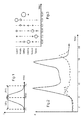
- the figure 1 is a curve representing the intensity of a vibratory excitation of a compressor constituting a motor vehicle of the present invention.
- the figure 2 is a curve representing the vibratory modes of a powertrain equipping a motor vehicle of the present invention.
- the figure 3 is a diagram representing an intensity of each vibratory mode according to its frequency.
- a motor vehicle is commonly equipped with an internal combustion engine to provide for its movement.
- the internal combustion engine is capable of running at idling speed R.
- the internal combustion engine is equipped with a crankshaft to convert reciprocating rectilinear motion into circular motion.
- the crankshaft is in relation to a first crankshaft accessory pulley.
- the internal combustion engine is a powertrain that is housed inside the engine compartment.
- the powertrain is based on the body of the motor vehicle, in other words on the skeleton of the car, by means of suspension blocks.
- the motor vehicle is commonly also equipped with an air conditioning loop to change a temperature of a flow of air before delivery of the latter inside a passenger compartment of the motor vehicle.
- the air conditioning loop is likely to operate in heat pump mode when an outside temperature is for example below -20 ° C, and in cooling mode, when the outside temperature is above 20 ° C.
- the air conditioning loop is in particular equipped with a compressor for compressing a refrigerant circulating inside the air conditioning loop.
- the air conditioning loop also comprises an expansion member inside which the cooling fluid undergoes a relaxation.
- the air conditioning loop finally includes a heater and a heat exchanger for exchanging heat with a respective environment.
- the compressor includes parts that are rotated to compress the coolant.
- the compressor is in relation with a second pulley which is in mechanical relation with a shaft associated with the internal combustion engine.
- the rotation of the compressor generates a vibratory excitation which is likely to be transmitted to the body of the motor vehicle, in particular by means of suspension wedges interposed between the powertrain and the body.
- the powertrain comprises a maximum frequency F of vibration on the suspension blocks. Such transmission of vibratory excitations is likely to cause vibration and / or noise pollution inside the passenger compartment of the motor vehicle.
- the present invention proposes to position said vibratory excitation so that the latter is distinct from amplifications of vibratory modes of the powertrain on said suspension wedges. In other words, it is proposed to increase a speed of rotation between the first pulley associated with the crankshaft of the internal combustion engine and the second pulley associated with the compressor.
- the gear ratio D satisfies the following inequality [1]: Cs x F x 60 / R ⁇ D
- Cs is a safety factor.
- the coefficient 60 corresponds to the conversion of the frequency F expressed in hertz in revolutions per minute, the idling speed R being expressed in revolutions / minute.
- the coefficient of safety Cs avoids a transmission of vibratory energy carried by the frequencies below the curve of the figure 2 which is framed by minimum frequencies F 1 and maximum F 2 , respectively less than 25% and greater than 25%, with respect to a maximum frequency F max , for which the intensity is maximum as illustrated in FIG. figure 1 .
- the safety coefficient Cs may be smaller but preferably greater than 1.15, ie +/- 15% of the maximum frequency to limit the transmission of vibrational energy.
- the gear ratio D satisfies the following inequality [2]: Cs x F x 60 / R x N ⁇ D
- the coefficient Cs corresponds to the safety coefficient already described
- the coefficient 60 corresponds to the conversion of the frequency F expressed in Hertz in revolutions / minutes, the idling speed R being expressed in revolutions / minutes and the harmonic of rank N being an integer strictly greater than zero.
- the present invention also proposes a method for implementing such a motor vehicle which comprises a first step of identifying the vibration modes of the powertrain on said suspension blocks, as shown in FIG. figure 2 .
- the first step is followed by a second step of determining the highest frequency of the vibration modes of the powertrain.
- each mode of vibration is represented as a function of frequency, the diameter of each circle being a function of the vibratory intensity identified, it is notable on the example illustrated that the gallop mode covers the most important vibratory intensity for a frequency 18.85 Hz.
- the second step is then followed by a third step of calculating a better between the gear ratio D and the idle speed R to satisfy as appropriate the inequalities [1] and [2] referred to above.
- the method comprises a fourth step of limiting a power of the compressor.
- the level of limitation depends on the architecture of the compressor and the power of the compressor. A limitation to about 75% of the maximum power of the compressor is a good compromise to maintain the air conditioning function.
Landscapes
- Engineering & Computer Science (AREA)
- Chemical & Material Sciences (AREA)
- Combustion & Propulsion (AREA)
- Mechanical Engineering (AREA)
- Transportation (AREA)
- General Engineering & Computer Science (AREA)
- Physics & Mathematics (AREA)
- Thermal Sciences (AREA)
- Air-Conditioning For Vehicles (AREA)
- Compressors, Vaccum Pumps And Other Relevant Systems (AREA)
Abstract

dans laquelle Cs correspond à un coefficient de sécurité.
Description
- L'invention porte sur un véhicule automobile équipé d'un moteur à combustion thermique constitutif d'un groupe motopropulseur porté par des cales de suspension, le moteur à combustion interne étant pourvu d'une première poulie associée à un vilebrequin et d'une deuxième poulie associée à un compresseur équipant une boucle de climatisation.
- Le document
EP0956985 décrit un procédé et un dispositif pour supprimer une résonance d'un tuyau sous pression lorsqu'un fluide sous pression s'écoule depuis une zone de mise sous pression de façon intermittente le long d'un passage de fluide que comprend le tuyau. Le procédé est caractérisé par la fourniture d'un corps de soupape mobile situé dans le passage du fluide, dans lequel le corps de soupape peut être déplacé par l'écoulement du fluide sous pression, par la limitation du mouvement du corps de soupape par une force de limitation prédéterminée et par la détermination de la force de limitation de sorte que la fréquence de variation de pression de fluide sous pression s'écoulant dans le tuyau change de façon à être sensiblement différente de la fréquence naturelle du tuyau ou de sorte que l'amplitude de la variation de pression de fluide sous pression s'écoulant dans le tuyau soit réduite. - Le tuyau est un tuyau participant d'une boucle de climatisation qui est prévue pour modifier une température d'un flux d'air préalablement à une admission de ce dernier à l'intérieur d'un habitacle du véhicule automobile. La boucle de climatisation comprend un compresseur pour comprimer le fluide sous pression.
- Un inconvénient d'un tel compresseur réside dans une aptitude de ce dernier à générer des excitations vibratoires qui sont transmises à l'intérieur de l'habitacle et qui génèrent une gêne vibratoire et/ou acoustique pour un utilisateur présent à l'intérieur de l'habitacle. De plus, la boucle de climatisation est susceptible de fonctionner en mode pompe à chaleur lorsqu'une température extérieure est par exemple inférieure à -20°C et en mode climatisation lorsque la température extérieure est supérieure à 20°C, il en résulte qu'une fréquence de gêne vibratoire et/ou acoustique est excessive, notamment lorsque le compresseur fonctionne à pleine puissance. Il en ressort finalement qu'un agencement d'un tel véhicule automobile mérite d'être amélioré.
- Un but de la présente invention est de proposer un véhicule automobile qui est agencé pour limiter une gêne acoustique et/ou vibratoire pour un utilisateur présent à l'intérieur d'un habitacle du véhicule automobile, une telle gêne étant limitée quelle que soit la température extérieure au véhicule automobile et quel que soit la puissance générée par un compresseur constitutif d'une boucle de climatisation équipant le véhicule automobile.
- Un véhicule automobile de la présente invention est un véhicule automobile équipé d'un moteur à combustion thermique constitutif d'un groupe motopropulseur porté par des cales de suspension, le moteur à combustion interne étant pourvu d'une première poulie associée à un vilebrequin et d'une deuxième poulie associée à un compresseur équipant une boucle de climatisation, la première poulie et la deuxième poulie comportant un rapport de démultiplication D, le moteur à combustion interne comportant un régime de ralenti R, le groupe motopropulseur comportant une fréquence maximale F de vibration sur les cales de suspension.
- Selon la présente invention, le rapport de démultiplication D vérifie l'inéquation [1] suivante :

- Le compresseur générant une excitation vibratoire comportant une harmonique de rang N correspondant à un nombre de pistons du compresseur, le rapport de démultiplication D vérifie préférentiellement l'inéquation [2] suivante :

- Le coefficient de sécurité Cs est de préférence supérieur à 1,15. Un bon compromis est obtenu pour un coefficient de sécurité Cs de 1,25.
- Les cales de suspension sont préférentiellement interposées entre le groupe motopropulseur et la caisse du véhicule automobile.
- Un procédé de mise en oeuvre d'un véhicule automobile de la présente invention est principalement reconnaissable en ce que le procédé comprend une première étape d'identification de modes de vibration du groupe motopropulseur sur les dites cales de suspension.
- Le procédé comprend avantageusement une deuxième étape de détermination de la fréquence la plus élevée des modes de vibration du groupe motopropulseur.
- Le procédé comprend avantageusement une troisième étape de calcul d'un meilleur compris entre le rapport de démultiplication D et le régime de ralenti R pour satisfaire l'inéquation [1].
- Le procédé comprend avantageusement une quatrième étape de limitation d'une puissance du compresseur. Avantageusement, la puissance du compresseur est limitée à 75% de sa puissance maximale.
- D'autres caractéristiques et avantages de la présente invention apparaîtront à la lecture de la description qui va en être faite d'exemples de réalisation, en relation avec les figures de la planche annexée, dans laquelle :
- La
figure 1 est une courbe représentant l'intensité d'une excitation vibratoire d'un compresseur constitutif d'un véhicule automobile de la présente invention. - La
figure 2 est une courbe représentant les modes vibratoires d'un groupe motopropulseur équipant un véhicule automobile de la présente invention. - La
figure 3 est un diagramme représentant une intensité de chaque mode vibratoire en fonction de sa fréquence. - Un véhicule automobile est couramment équipé d'un moteur à combustion interne pour pourvoir à son déplacement. Le moteur à combustion interne est susceptible de tourner à un régime de ralenti R. Le moteur à combustion interne est équipé d'un vilebrequin pour convertir un mouvement rectiligne alternatif en mouvement circulaire. Le vilebrequin est en relation avec une première poulie d'accessoires-vilebrequin. Le moteur à combustion interne est constitutif d'un groupe motopropulseur qui est logé à l'intérieur du compartiment moteur. Le groupe motopropulseur repose sur la caisse du véhicule automobile, autrement dit sur le squelette de la voiture, par l'intermédiaire de cales de suspension.
- Le véhicule automobile est couramment aussi équipé d'une boucle de climatisation pour modifier une température d'un flux d'air préalablement à une délivrance de ce dernier à l'intérieur d'un habitacle du véhicule automobile. La boucle de climatisation est susceptible de fonctionner en mode pompe à chaleur lorsqu'une température extérieure est par exemple inférieure à -20°C, et en mode climatisation, lorsque la température extérieure est supérieure à 20°C. La boucle de climatisation est notamment équipée d'un compresseur pour comprimer un fluide réfrigérant circulant à l'intérieur de la boucle de climatisation. La boucle de climatisation comprend aussi un organe de détente à l'intérieur duquel le fluide réfrigérant subit une détente. La boucle de climatisation comprend enfin un aérotherme et un échangeur de chaleur pour échanger de la chaleur avec un milieu environnant respectif.
- Le compresseur comprend des pièces qui sont mises en rotation pour comprimer le fluide réfrigérant. Le compresseur est en relation avec une deuxième poulie qui est en relation mécanique avec un arbre associé au moteur à combustion interne. La mise en rotation du compresseur engendre une excitation vibratoire qui est susceptible d'être transmise à la caisse du véhicule automobile, notamment par l'intermédiaire des cales de suspension interposées entre le groupe motopropulseur et la caisse. Plus particulièrement, le groupe motopropulseur comporte une fréquence maximale F de vibration sur les cales de suspension. Une telle transmission d'excitations vibratoires est susceptible de provoquer des nuisances vibratoires et/ou sonores à l'intérieur de l'habitacle du véhicule automobile.
- Dans sa généralité, la présente invention propose de positionner ladite excitation vibratoire de manière à ce que cette dernière soit distincte d'amplifications de modes vibratoires du groupe motopropulseur sur les dites cales de suspension. Autrement dit, il est proposé de démultiplier une vitesse de rotation entre la première poulie associée au vilebrequin du moteur à combustion interne et la deuxième poulie associée au compresseur.
- Plus particulièrement, dans le cas où la première poulie et la deuxième poulie comportent un rapport de démultiplication D, le rapport de démultiplication D vérifie l'inéquation [1] suivante :

- Dans laquelle Cs correspond à un coefficient de sécurité. Le coefficient 60 correspond à la conversion de la fréquence F exprimée en hertz en tours par minute, le régime de ralenti R étant exprimé en tours/minutes. Le coefficient de sécurité Cs évite une transmission d'énergie vibratoire portée par les fréquences situées sous la courbe de la
figure 2 qui est encadrée par des fréquences minimale F1 et maximale F2, respectivement inférieure de 25% et supérieur de 25%, par rapport à une fréquence maximale Fmax, pour laquelle l'intensité est maximale tel qu'illustré sur lafigure 1 . Un résultat optimum est obtenu pour un coefficient de sécurité de 1,25, soit +/- 25% de la fréquence maximum, comme dans lafigure 1 , cependant, le coefficient de sécurité Cs peut être moindre mais de préférence supérieur à 1,15, soit +/-15% de la fréquence maximum pour limiter la transmission d'énergie vibratoire. - Plus particulièrement encore, dans le cas où le compresseur génère une excitation vibratoire comportant une harmonique de rang N correspondant à un nombre de pistons du compresseur, le rapport de démultiplication D vérifie l'inéquation [2] suivante :

- Dans laquelle, le coefficient Cs correspond au coefficient de sécurité déjà décrit, le coefficient 60 correspond à la conversion de la fréquence F exprimée en Hertz en tours/minutes, le régime de ralenti R étant exprimé en tours/minutes et l'harmonique de rang N étant un nombre entier strictement supérieur à zéro.
- La présente invention propose également un procédé de mise en oeuvre d'un tel véhicule automobile qui comporte une première étape d'identification des modes de vibration du groupe motopropulseur sur les dites cales de suspension, tels que représentés sur la
figure 2 . - La première étape est suivie d'une deuxième étape de détermination de la fréquence la plus élevée des modes de vibration du groupe motopropulseur. Sur la
figure 3 où est représenté chaque mode de vibration en fonction de la fréquence, le diamètre de chaque cercle étant fonction de l'intensité vibratoire identifiée, il est notable sur l'exemple illustré que le mode galop recouvre l'intensité vibratoire la plus importante pour une fréquence de 18,85 Hz. - La deuxième étape est alors suivie d'une troisième étape de calcul d'un meilleur compris entre le rapport de démultiplication D et le régime de ralenti R pour satisfaire selon le cas aux inéquations [1] et [2] susvisées.
- Dans le cas où les inéquations [1] et [2] susvisées ne sont pas satisfaites, notamment en raison des contraintes mécaniques du compresseur, le procédé comprend une quatrième étape de limitation d'une puissance du compresseur. Le niveau de limitation dépend de l'architecture du compresseur et de la puissance du compresseur. Une limitation à environ 75% de la puissance maximale du compresseur est un bon compromis permettant de conserver la fonction de climatisation.
Claims (10)
- Véhicule automobile équipé d'un moteur à combustion thermique constitutif d'un groupe motopropulseur porté par des cales de suspension, le moteur à combustion interne étant pourvu d'une première poulie associée à un vilebrequin et d'une deuxième poulie associée à un compresseur équipant une boucle de climatisation, la première poulie et la deuxième poulie comportant un rapport de démultiplication D, le moteur à combustion interne comportant un régime de ralenti R, le groupe motopropulseur comportant une fréquence maximale F de vibration sur les cales de suspension, caractérisé en ce que le rapport de démultiplication D vérifie l'inéquation [1] suivante :

dans laquelle Cs correspond à un coefficient de sécurité. - Véhicule automobile selon la revendication 1, le compresseur générant une excitation vibratoire comportant une harmonique de rang N correspondant à un nombre de pistons du compresseur, caractérisé en ce que le rapport de démultiplication D vérifie l'inéquation [2] suivante :

- Véhicule selon la revendication 1, caractérisé en ce que le coefficient de sécurité Cs supérieur à 1,15.
- Véhicule selon la revendication 2, caractérisé en ce que le coefficient de sécurité Cs est de 1,25.
- Véhicule automobile selon l'une quelconque des revendications précédentes, caractérisé en ce que les cales de suspension sont interposées entre le groupe motopropulseur et la caisse du véhicule automobile.
- Procédé de mise en oeuvre d'un véhicule automobile selon l'une quelconque des revendications précédentes, caractérisé en ce que le procédé comprend une première étape d'identification de modes de vibration du groupe motopropulseur sur les dites cales de suspension.
- Procédé selon la revendication 6, caractérisé en ce que le procédé comprend une deuxième étape de détermination de la fréquence la plus élevée des modes de vibration du groupe motopropulseur.
- Procédé selon la revendication 7, caractérisé en ce que le procédé comprend une troisième étape de calcul d'un meilleur compris entre le rapport de démultiplication D et le régime de ralenti R pour satisfaire l'inéquation [1].
- Procédé selon la revendication 8, caractérisé en ce que le procédé comprend une quatrième étape de limitation d'une puissance du compresseur.
- Procédé selon la revendication 9, caractérisé en ce que la puissance du compresseur est limitée à 75% de sa puissance maximale.
Applications Claiming Priority (1)
| Application Number | Priority Date | Filing Date | Title |
|---|---|---|---|
| FR1359382A FR3011275B1 (fr) | 2013-09-30 | 2013-09-30 | Vehicule automobile agence pour reduire des excitations vibratoires d'un compresseur de climatisation |
Publications (1)
| Publication Number | Publication Date |
|---|---|
| EP2853769A1 true EP2853769A1 (fr) | 2015-04-01 |
Family
ID=49551691
Family Applications (1)
| Application Number | Title | Priority Date | Filing Date |
|---|---|---|---|
| EP14184121.3A Withdrawn EP2853769A1 (fr) | 2013-09-30 | 2014-09-09 | Véhicule automobile agence pour reduire des excitations vibratoires d'un compresseur de climatisation |
Country Status (2)
| Country | Link |
|---|---|
| EP (1) | EP2853769A1 (fr) |
| FR (1) | FR3011275B1 (fr) |
Cited By (1)
| Publication number | Priority date | Publication date | Assignee | Title |
|---|---|---|---|---|
| CN115114754A (zh) * | 2022-06-27 | 2022-09-27 | 中国第一汽车股份有限公司 | 一种车辆空调管路避频设计方法 |
Families Citing this family (1)
| Publication number | Priority date | Publication date | Assignee | Title |
|---|---|---|---|---|
| CN112254299B (zh) * | 2020-09-29 | 2021-10-29 | 青岛海尔空调器有限总公司 | 用于控制制冷设备的方法及装置、制冷设备 |
Citations (5)
| Publication number | Priority date | Publication date | Assignee | Title |
|---|---|---|---|---|
| EP0956985A1 (fr) | 1998-05-11 | 1999-11-17 | Kabushiki Kaisha Toyoda Jidoshokki Seisakusho | Procédé et dispositif pour supprimer la résonance |
| US20020011229A1 (en) * | 2000-03-28 | 2002-01-31 | Yasuyuki Asahara | Vibration reducing system for internal combustion engine |
| EP1624549A2 (fr) * | 2004-08-06 | 2006-02-08 | Denso Corporation | Alternateur entraîné par courroie d'un moteur à combustion interne |
| US20060223662A1 (en) * | 2005-03-31 | 2006-10-05 | Denso Corporation | Alternator for vehicles |
| WO2007074016A1 (fr) * | 2005-12-24 | 2007-07-05 | Schaeffler Kg | Entrainement a mecanisme de traction pour moteur a combustion interne |
-
2013
- 2013-09-30 FR FR1359382A patent/FR3011275B1/fr not_active Expired - Fee Related
-
2014
- 2014-09-09 EP EP14184121.3A patent/EP2853769A1/fr not_active Withdrawn
Patent Citations (5)
| Publication number | Priority date | Publication date | Assignee | Title |
|---|---|---|---|---|
| EP0956985A1 (fr) | 1998-05-11 | 1999-11-17 | Kabushiki Kaisha Toyoda Jidoshokki Seisakusho | Procédé et dispositif pour supprimer la résonance |
| US20020011229A1 (en) * | 2000-03-28 | 2002-01-31 | Yasuyuki Asahara | Vibration reducing system for internal combustion engine |
| EP1624549A2 (fr) * | 2004-08-06 | 2006-02-08 | Denso Corporation | Alternateur entraîné par courroie d'un moteur à combustion interne |
| US20060223662A1 (en) * | 2005-03-31 | 2006-10-05 | Denso Corporation | Alternator for vehicles |
| WO2007074016A1 (fr) * | 2005-12-24 | 2007-07-05 | Schaeffler Kg | Entrainement a mecanisme de traction pour moteur a combustion interne |
Cited By (1)
| Publication number | Priority date | Publication date | Assignee | Title |
|---|---|---|---|---|
| CN115114754A (zh) * | 2022-06-27 | 2022-09-27 | 中国第一汽车股份有限公司 | 一种车辆空调管路避频设计方法 |
Also Published As
| Publication number | Publication date |
|---|---|
| FR3011275B1 (fr) | 2018-01-12 |
| FR3011275A1 (fr) | 2015-04-03 |
Similar Documents
| Publication | Publication Date | Title |
|---|---|---|
| CN112673188B (zh) | 组合的隔离及扭转振动阻尼装置 | |
| US20150107950A1 (en) | Lockup torque converter with multi-rate damper | |
| Zouani et al. | Overview of noise and vibration in automotive engines | |
| JP2017526883A (ja) | 1つ以上のエラストマ部材を収容したカートリッジを備えたドライブシステムのための装置 | |
| FR3011275A1 (fr) | Vehicule automobile agence pour reduire des excitations vibratoires d'un compresseur de climatisation | |
| CN203627592U (zh) | 一种汽车发动机轮系的发电机超越皮带轮 | |
| KR20200037433A (ko) | 비균일 탄성중합체 프로파일을 구비한 비틀림 진동 댐퍼 | |
| Priede | Problems and developments in automotive engine noise research | |
| US10295015B2 (en) | Torsional vibration dampers having dual elastomeric members | |
| FR2802263A1 (fr) | Moteur a combustion comportant au moins un arbre de compensation | |
| JP2018017277A (ja) | プーリユニット | |
| EP1977143B1 (fr) | Poulie de vilebrequin | |
| WO2016063456A1 (fr) | Palier à douille flottant et turbine d'échappement de navire | |
| FR2963073A1 (fr) | Procede de reduction de la consommation de carburant d'un moteur thermique equipant un vehicule et vehicule associe | |
| Ohta et al. | Study on the noise and vibration of engine block coupled with the rotating crankshaft and gear train (Effect of the torsional vibration of crankshaft) | |
| Stahl et al. | Planetary centrifugal pendulum absorber (pCPA)–new type of centrifugal pendulum absorber for applications in highly downsized hybrid and range extender combustion engines | |
| KR102581054B1 (ko) | 차량용 발전기 | |
| Nakagawa et al. | Numerical Study of the Effect of the Damping Ratio of the Internal Transmission System on the Combustion-induced Vibration of a Diesel Engine | |
| JP2002310299A (ja) | 組合せオイルリング用サイドレール | |
| JP2005344560A (ja) | 可変圧縮比内燃機関 | |
| FR3012847A1 (fr) | Procede d'attenuation d'un couple d'agrement curatif en cas d'activation d'un regulateur de ralenti et calculateur moteur correspondant | |
| FR3014148B1 (fr) | Collecteur d'admission d'air pour moteur thermique comprenant un attenuateur acoustique | |
| JP6691458B2 (ja) | ダンパ装置 | |
| FR2980536A1 (fr) | Methode de mise en oeuvre d'un turbocompresseur d'un vehicule automobile | |
| FR3059488A1 (fr) | Machine electrique pour vehicule automobile |
Legal Events
| Date | Code | Title | Description |
|---|---|---|---|
| PUAI | Public reference made under article 153(3) epc to a published international application that has entered the european phase |
Free format text: ORIGINAL CODE: 0009012 |
|
| 17P | Request for examination filed |
Effective date: 20140909 |
|
| AK | Designated contracting states |
Kind code of ref document: A1 Designated state(s): AL AT BE BG CH CY CZ DE DK EE ES FI FR GB GR HR HU IE IS IT LI LT LU LV MC MK MT NL NO PL PT RO RS SE SI SK SM TR |
|
| AX | Request for extension of the european patent |
Extension state: BA ME |
|
| R17P | Request for examination filed (corrected) |
Effective date: 20150827 |
|
| RBV | Designated contracting states (corrected) |
Designated state(s): AL AT BE BG CH CY CZ DE DK EE ES FI FR GB GR HR HU IE IS IT LI LT LU LV MC MK MT NL NO PL PT RO RS SE SI SK SM TR |
|
| 17Q | First examination report despatched |
Effective date: 20160209 |
|
| RIC1 | Information provided on ipc code assigned before grant |
Ipc: F16F 15/00 20060101AFI20160914BHEP Ipc: F02B 67/06 20060101ALN20160914BHEP Ipc: B60W 10/30 20060101ALN20160914BHEP Ipc: F16H 7/02 20060101ALI20160914BHEP |
|
| GRAP | Despatch of communication of intention to grant a patent |
Free format text: ORIGINAL CODE: EPIDOSNIGR1 |
|
| RIC1 | Information provided on ipc code assigned before grant |
Ipc: F02B 67/06 20060101ALN20161116BHEP Ipc: F16H 7/02 20060101ALI20161116BHEP Ipc: F16F 15/00 20060101AFI20161116BHEP Ipc: B60W 10/30 20060101ALN20161116BHEP |
|
| INTG | Intention to grant announced |
Effective date: 20161220 |
|
| RAP1 | Party data changed (applicant data changed or rights of an application transferred) |
Owner name: PSA AUTOMOBILES SA |
|
| STAA | Information on the status of an ep patent application or granted ep patent |
Free format text: STATUS: THE APPLICATION IS DEEMED TO BE WITHDRAWN |
|
| 18D | Application deemed to be withdrawn |
Effective date: 20170503 |