EP2853768A1 - Suspension device - Google Patents
Suspension device Download PDFInfo
- Publication number
- EP2853768A1 EP2853768A1 EP20130793394 EP13793394A EP2853768A1 EP 2853768 A1 EP2853768 A1 EP 2853768A1 EP 20130793394 EP20130793394 EP 20130793394 EP 13793394 A EP13793394 A EP 13793394A EP 2853768 A1 EP2853768 A1 EP 2853768A1
- Authority
- EP
- European Patent Office
- Prior art keywords
- variable throttle
- throttle member
- acting portion
- suspension apparatus
- actuator
- Prior art date
- Legal status (The legal status is an assumption and is not a legal conclusion. Google has not performed a legal analysis and makes no representation as to the accuracy of the status listed.)
- Withdrawn
Links
Images





Classifications
-
- B—PERFORMING OPERATIONS; TRANSPORTING
- B62—LAND VEHICLES FOR TRAVELLING OTHERWISE THAN ON RAILS
- B62K—CYCLES; CYCLE FRAMES; CYCLE STEERING DEVICES; RIDER-OPERATED TERMINAL CONTROLS SPECIALLY ADAPTED FOR CYCLES; CYCLE AXLE SUSPENSIONS; CYCLE SIDECARS, FORECARS, OR THE LIKE
- B62K25/00—Axle suspensions
- B62K25/04—Axle suspensions for mounting axles resiliently on cycle frame or fork
- B62K25/28—Axle suspensions for mounting axles resiliently on cycle frame or fork with pivoted chain-stay
- B62K25/283—Axle suspensions for mounting axles resiliently on cycle frame or fork with pivoted chain-stay for cycles without a pedal crank, e.g. motorcycles
-
- B—PERFORMING OPERATIONS; TRANSPORTING
- B62—LAND VEHICLES FOR TRAVELLING OTHERWISE THAN ON RAILS
- B62K—CYCLES; CYCLE FRAMES; CYCLE STEERING DEVICES; RIDER-OPERATED TERMINAL CONTROLS SPECIALLY ADAPTED FOR CYCLES; CYCLE AXLE SUSPENSIONS; CYCLE SIDECARS, FORECARS, OR THE LIKE
- B62K25/00—Axle suspensions
- B62K25/04—Axle suspensions for mounting axles resiliently on cycle frame or fork
- B62K25/06—Axle suspensions for mounting axles resiliently on cycle frame or fork with telescopic fork, e.g. including auxiliary rocking arms
-
- B—PERFORMING OPERATIONS; TRANSPORTING
- B62—LAND VEHICLES FOR TRAVELLING OTHERWISE THAN ON RAILS
- B62K—CYCLES; CYCLE FRAMES; CYCLE STEERING DEVICES; RIDER-OPERATED TERMINAL CONTROLS SPECIALLY ADAPTED FOR CYCLES; CYCLE AXLE SUSPENSIONS; CYCLE SIDECARS, FORECARS, OR THE LIKE
- B62K25/00—Axle suspensions
- B62K25/04—Axle suspensions for mounting axles resiliently on cycle frame or fork
- B62K25/06—Axle suspensions for mounting axles resiliently on cycle frame or fork with telescopic fork, e.g. including auxiliary rocking arms
- B62K25/10—Axle suspensions for mounting axles resiliently on cycle frame or fork with telescopic fork, e.g. including auxiliary rocking arms for rear wheel
-
- B—PERFORMING OPERATIONS; TRANSPORTING
- B62—LAND VEHICLES FOR TRAVELLING OTHERWISE THAN ON RAILS
- B62K—CYCLES; CYCLE FRAMES; CYCLE STEERING DEVICES; RIDER-OPERATED TERMINAL CONTROLS SPECIALLY ADAPTED FOR CYCLES; CYCLE AXLE SUSPENSIONS; CYCLE SIDECARS, FORECARS, OR THE LIKE
- B62K25/00—Axle suspensions
- B62K25/04—Axle suspensions for mounting axles resiliently on cycle frame or fork
- B62K25/28—Axle suspensions for mounting axles resiliently on cycle frame or fork with pivoted chain-stay
-
- F—MECHANICAL ENGINEERING; LIGHTING; HEATING; WEAPONS; BLASTING
- F16—ENGINEERING ELEMENTS AND UNITS; GENERAL MEASURES FOR PRODUCING AND MAINTAINING EFFECTIVE FUNCTIONING OF MACHINES OR INSTALLATIONS; THERMAL INSULATION IN GENERAL
- F16F—SPRINGS; SHOCK-ABSORBERS; MEANS FOR DAMPING VIBRATION
- F16F9/00—Springs, vibration-dampers, shock-absorbers, or similarly-constructed movement-dampers using a fluid or the equivalent as damping medium
- F16F9/32—Details
- F16F9/44—Means on or in the damper for manual or non-automatic adjustment; such means combined with temperature correction
- F16F9/46—Means on or in the damper for manual or non-automatic adjustment; such means combined with temperature correction allowing control from a distance, i.e. location of means for control input being remote from site of valves, e.g. on damper external wall
- F16F9/461—Means on or in the damper for manual or non-automatic adjustment; such means combined with temperature correction allowing control from a distance, i.e. location of means for control input being remote from site of valves, e.g. on damper external wall characterised by actuation means
-
- F—MECHANICAL ENGINEERING; LIGHTING; HEATING; WEAPONS; BLASTING
- F16—ENGINEERING ELEMENTS AND UNITS; GENERAL MEASURES FOR PRODUCING AND MAINTAINING EFFECTIVE FUNCTIONING OF MACHINES OR INSTALLATIONS; THERMAL INSULATION IN GENERAL
- F16F—SPRINGS; SHOCK-ABSORBERS; MEANS FOR DAMPING VIBRATION
- F16F9/00—Springs, vibration-dampers, shock-absorbers, or similarly-constructed movement-dampers using a fluid or the equivalent as damping medium
- F16F9/32—Details
- F16F9/44—Means on or in the damper for manual or non-automatic adjustment; such means combined with temperature correction
- F16F9/46—Means on or in the damper for manual or non-automatic adjustment; such means combined with temperature correction allowing control from a distance, i.e. location of means for control input being remote from site of valves, e.g. on damper external wall
- F16F9/466—Throttling control, i.e. regulation of flow passage geometry
-
- F—MECHANICAL ENGINEERING; LIGHTING; HEATING; WEAPONS; BLASTING
- F16—ENGINEERING ELEMENTS AND UNITS; GENERAL MEASURES FOR PRODUCING AND MAINTAINING EFFECTIVE FUNCTIONING OF MACHINES OR INSTALLATIONS; THERMAL INSULATION IN GENERAL
- F16F—SPRINGS; SHOCK-ABSORBERS; MEANS FOR DAMPING VIBRATION
- F16F9/00—Springs, vibration-dampers, shock-absorbers, or similarly-constructed movement-dampers using a fluid or the equivalent as damping medium
- F16F9/32—Details
- F16F9/56—Means for adjusting the length of, or for locking, the spring or damper, e.g. at the end of the stroke
-
- B—PERFORMING OPERATIONS; TRANSPORTING
- B62—LAND VEHICLES FOR TRAVELLING OTHERWISE THAN ON RAILS
- B62K—CYCLES; CYCLE FRAMES; CYCLE STEERING DEVICES; RIDER-OPERATED TERMINAL CONTROLS SPECIALLY ADAPTED FOR CYCLES; CYCLE AXLE SUSPENSIONS; CYCLE SIDECARS, FORECARS, OR THE LIKE
- B62K25/00—Axle suspensions
- B62K25/04—Axle suspensions for mounting axles resiliently on cycle frame or fork
- B62K2025/044—Suspensions with automatic adjustment
-
- B—PERFORMING OPERATIONS; TRANSPORTING
- B62—LAND VEHICLES FOR TRAVELLING OTHERWISE THAN ON RAILS
- B62K—CYCLES; CYCLE FRAMES; CYCLE STEERING DEVICES; RIDER-OPERATED TERMINAL CONTROLS SPECIALLY ADAPTED FOR CYCLES; CYCLE AXLE SUSPENSIONS; CYCLE SIDECARS, FORECARS, OR THE LIKE
- B62K25/00—Axle suspensions
- B62K25/04—Axle suspensions for mounting axles resiliently on cycle frame or fork
- B62K2025/045—Suspensions with ride-height adjustment
-
- B—PERFORMING OPERATIONS; TRANSPORTING
- B62—LAND VEHICLES FOR TRAVELLING OTHERWISE THAN ON RAILS
- B62K—CYCLES; CYCLE FRAMES; CYCLE STEERING DEVICES; RIDER-OPERATED TERMINAL CONTROLS SPECIALLY ADAPTED FOR CYCLES; CYCLE AXLE SUSPENSIONS; CYCLE SIDECARS, FORECARS, OR THE LIKE
- B62K25/00—Axle suspensions
- B62K25/04—Axle suspensions for mounting axles resiliently on cycle frame or fork
- B62K2025/048—Axle suspensions for mounting axles resiliently on cycle frame or fork with suspension manual adjustment details
Definitions
- the present invention relates to an improvement in a suspension apparatus.
- a suspension apparatus is interposed between a vehicle body and a vehicle wheel in order to suppress transmission of an impact generated by irregularities on a road surface or the like to the vehicle body.
- JP2011-117493A discloses a front fork that suspends a front wheel of a motorcycle.
- the front fork includes a suspension apparatus main body constituted by an outer tube connected to a vehicle body side and an inner tube coupled to a vehicle wheel side and inserted retractably into the outer tube.
- a shock absorber and a suspension spring are housed in parallel inside the suspension apparatus main body.
- the shock absorber includes a pair of chambers defined by a piston within a cylinder, a flow passage formed in the piston to connect the pair of chambers in the cylinder, and damping force generating means for applying resistance to a working fluid passing through the flow passage.
- the shock absorber includes a bypass passage that connects the pair of chambers in the cylinder so as to bypass the flow passage in which the damping force generating means is provided, a variable throttle member that is inserted into the bypass passage to be capable of advancing and retreating in order to modify an opening of the bypass passage, and an actuator that drives the variable throttle member.
- a vehicle body side attachment member for connecting the shock absorber to the vehicle body side is preferably provided on a central axis of the shock absorber.
- the variable throttle member, the actuator, and the vehicle body side attachment member are arranged longitudinally along the central axis of the shock absorber.
- variable throttle member and the vehicle body side attachment member are removed from each other, leading to an increase in a distance between a vehicle wheel side attachment member for connecting the shock absorber to the vehicle wheel side and the vehicle body side attachment member.
- an attachment dimension of the suspension apparatus lengthens, and as a result, a stroke length of the suspension apparatus may be restricted.
- the shock absorber when the shock absorber is set in an inverted orientation such that the actuator is disposed on the vehicle wheel side, the variable throttle member, the actuator, and the vehicle wheel side attachment member are arranged longitudinally along the central axis of the shock absorber. Likewise in this case, therefore, the attachment dimension of the suspension apparatus lengthens, and as a result, the stroke length of the suspension apparatus may be restricted.
- the present invention has been designed in consideration of the problems described above, and an object thereof is to shorten an attachment dimension of a suspension apparatus even in a case where an actuator is disposed on a vehicle body side such that a vehicle body side attachment member and a variable throttle member are disposed along a central axis of a shock absorber, or a case in which the actuator is disposed on a vehicle wheel side such that a vehicle wheel side attachment member and the variable throttle member are disposed along the central axis of the shock absorber.
- a suspension apparatus interposed between a vehicle body and a vehicle wheel.
- the suspension apparatus includes a shock absorber having a cylinder and a piston rod inserted retractably into the cylinder and a biasing member that biases the shock absorber in an expansion direction.
- the shock absorber includes a pair of chambers housing a working fluid, a flow passage that connects the pair of chambers such that the working fluid passes through the flow passage as the shock absorber expands and contracts, a damping force generation mechanism that is configured to apply resistance to the working fluid passing through the flow passage, a bypass passage that connects the pair of chambers so as to bypass the flow passage, a variable throttle member that is inserted into the bypass passage to be capable of advancing and retreating in order to modify an opening of the bypass passage, an actuator that is configured to drive the variable throttle member, and includes a motor, an acting portion disposed on a back surface side of the variable throttle member and provided eccentrically relative to the variable throttle member, and a motion conversion mechanism that is configured to convert a rotary motion of the motor into a linear motion of the acting portion, and a power transmission mechanism interposed between the acting portion and the variable throttle member in order to transmit the linear motion of the acting portion to the variable throttle member.
- a suspension apparatus 100 according to a first embodiment of the present invention will be described below with reference to the figures.
- Identical reference symbols used over a plurality of figures denote identical or corresponding components.
- the suspension apparatus 600 is a front fork suspending a front wheel of a motorcycle. As shown in FIG. 7 , the suspension apparatus 600 includes a suspension apparatus main body T constituted by an outer tube t1 connected to a vehicle body side, and an inner tube t2 connected to a vehicle wheel side and inserted retractably into the outer tube t1. A shock absorber D and a suspension spring (a biasing member) S are housed in parallel inside the suspension apparatus main body T.
- the shock absorber D includes a cylinder 1 connected to the vehicle wheel side, a piston rod 2 connected to the vehicle body side and inserted retractably into the cylinder 1, and a piston 7 held by the piston rod 2 so as to slide against an inner peripheral surface of the cylinder 1.
- the suspension spring S is interposed between a vehicle body side spring bearing s2 fixed to the piston rod 2 side and a vehicle wheel side spring bearing s1 fixed to the cylinder 1 side. The suspension spring S biases the shock absorber D in an expansion direction at all times.
- the shock absorber D includes a pair of chambers r1, r2 formed so as to be defined by the piston 7 within the cylinder 1 and filled with a working fluid, flow passages L1, L2 formed in the piston 7 to connect the pair of chambers r1, r2, and damping force generation mechanisms V3, V4 that apply resistance to working fluid passing through the flow passages L1, L2.
- the shock absorber D can generate a damping force resulting from the resistance applied by the damping force generation mechanisms V3, V4.
- the shock absorber D includes a bypass passage B that connects the pair of chambers r1, r2 so as to bypass the flow passages L1, L2, a variable throttle member 3 that is inserted into the bypass passage B to be capable of advancing and retreating in order to modify an opening of the bypass passage B, and an actuator 4 that drives the variable throttle member 3.
- the variable throttle member 3 includes a needle valve 31 inserted into the bypass passage B to be capable of advancing and retreating, and a push rod 30 interposed between the needle valve 31 and the actuator 4.
- the actuator 4 is attached to a cap member 25 that holds the piston rod 2.
- the actuator 4 includes a motor 40, an acting portion 41 that contacts a back surface of the push rod 30, and a motion conversion mechanism 42 that converts a rotary motion of the motor 40 into a linear motion of the acting portion 41.
- a flow rate of the working fluid passing through the flow passages L1, L2 in which the damping force generation mechanisms V3, V4 are provided can be modified by driving the variable throttle member 3 using the actuator 4 to modify the opening of the bypass passage B. According to the suspension apparatus 600, therefore, the damping force generated by the shock absorber D can be adjusted.
- the motor 40 is disposed on a spring of the suspension spring S. Hence, in the suspension apparatus 600, an impact input from the vehicle wheel side can be absorbed by the suspension spring S, with the result that direct input of the impact into the motor 40 can be suppressed.
- a vehicle body side attachment member for connecting the shock absorber D to the vehicle body side is preferably provided on a central axis of the shock absorber D.
- the variable throttle member 3, the actuator 4, and a vehicle body side attachment member 20 are arranged longitudinally along a central axis z of the shock absorber D.
- variable throttle member 3 and the vehicle body side attachment member 20 are removed from each other such that a distance between a vehicle wheel side attachment member (not shown) for connecting the shock absorber D to the vehicle wheel side and the vehicle body side attachment member 20 increases. Accordingly, an attachment dimension of the suspension apparatus 600 lengthens, and as a result, a stroke length of the suspension apparatus 600 may be restricted.
- the shock absorber D when the shock absorber D is set in an inverted orientation such that the actuator 4 is disposed on the vehicle wheel side, the variable throttle member 3, the actuator 4, and the vehicle wheel side attachment member are arranged longitudinally along the central axis z of the shock absorber D. Likewise in this case, therefore, the attachment dimension of the suspension apparatus 600 lengthens, and as a result, the stroke length of the suspension apparatus 600 may be restricted.
- the suspension apparatus 100 is interposed between a vehicle body and a vehicle wheel. As shown in FIG. 1 , the suspension apparatus 100 includes the shock absorber D having the cylinder 1 and the piston rod 2 inserted retractably into the cylinder 1, and the suspension spring S serving as a biasing member that biases the shock absorber D in the expansion direction at all times.
- the shock absorber D includes the pair of chambers r1, r2 in which the working fluid is housed, the flow passages L1, L2 that connect the pair of chambers r1, r2 so that the working fluid passes through the flow passages L1, L2 as the shock absorber D expands and contracts, the damping force generation mechanisms (an expansion side damping valve V1 and a contraction side damping valve V2) that apply resistance to the working fluid passing through the flow passages L1, L2, the bypass passage B that connects the pair of chambers r1, r2 so as to bypass the flow passages L1, L2, the variable throttle member 3 that is inserted into the bypass passage B to be capable of advancing and retreating in order to modify the opening of the bypass passage B, and the actuator 4 that drives the variable throttle member 3.
- the damping force generation mechanisms an expansion side damping valve V1 and a contraction side damping valve V2
- the actuator 4 includes the motor 40, the acting portion 41 disposed on a back surface side of the variable throttle member 3, and the motion conversion mechanism (not shown) that converts the rotary motion of the motor 40 into the linear motion of the acting portion 41.
- the acting portion 41 and the variable throttle member 3 are provided eccentrically.
- the shock absorber D includes a power transmission mechanism 5 that is interposed between the acting portion 41 and the variable throttle member 3 in order to transmit the linear motion of the acting portion 41 to the variable throttle member 3.
- the suspension apparatus 100 is a rear cushion unit that suspends a rear wheel of a motorcycle, a three-wheeled vehicle, or the like. Although not shown in the figures, the suspension apparatus 100 is interposed between the vehicle body and a swing arm that supports the rear wheel swingably.
- the cylinder 1 of the shock absorber D is connected to the swing arm via a vehicle wheel side attachment member 10.
- the piston rod 2 of the shock absorber D is connected to a frame serving as a skeleton of the vehicle body via the vehicle body side attachment member 20.
- the vehicle body side attachment member 20 is attached to a housing 21 connected to a base end portion 2a of the piston rod 2 projecting from the cylinder 1.
- the vehicle body side attachment member 20 is disposed on the central axis of the shock absorber D.
- a tubular spring guide 22 is held vertically on the piston rod 2 side (a lower side in FIG. 1 ) of the housing 21. The piston rod 2 is inserted into the spring guide 22.
- the vehicle body side spring bearing s2 is attached to an outer periphery of the spring guide 22 to be capable of moving in an axial direction.
- the vehicle wheel side spring bearing s1 is fixed to a vehicle wheel side end portion outer periphery of the cylinder 1.
- the suspension spring S that biases the shock absorber D in the expansion direction at all times is interposed between the vehicle wheel side spring bearing s1 and the vehicle body side spring bearing s2.
- a vehicle body side end portion of the suspension spring S is supported by the movable vehicle body side spring bearing s2.
- a fluid constituted by a liquid or a gas is supplied to and discharged from a jack chamber J formed on an opposite side (an upper side in FIG. 1 ) of the vehicle body side spring bearing s2 to the suspension spring S.
- the present invention is not limited to the configuration described above, and a configuration for holding the suspension spring S may be selected appropriately.
- the vehicle wheel side spring bearing s1 may be made movable and the vehicle body side spring bearing s2 may be fixed. Further, both the vehicle wheel side spring bearing s1 and the vehicle body side spring bearing s2 may be fixed.
- the cylinder 1 is formed in a closed-end tubular shape.
- a vehicle body side (the upper side in FIG. 1 ) opening of the cylinder 1 is closed by an annular rod guide 11.
- the shock absorber D includes a free piston 6 that is capable of moving in the axial direction so as to slide against a vehicle wheel side inner peripheral surface of the cylinder 1.
- a fluid chamber R and an air chamber A are defined within the cylinder 1 by the free piston 6.
- a working fluid constituted by oil, water, or a liquid such as an aqueous solution is charged into the fluid chamber R disposed on the rod guide 11 side (the upper side in FIG. 1 ) of the free piston 6.
- a gas is sealed into the air chamber A disposed on an opposite side (the lower side in FIG. 1 ) of the rod guide 11.
- a tubular bearing 12 that supports the piston rod 2 to be free to move in the axial direction is fitted to an inner periphery of the rod guide 11.
- the piston rod 2 is supported on the rod guide 11 via the bearing 12.
- a tip end side of the piston rod 2 advances into and retracts from the fluid chamber R.
- An annular dust seal 13 is laminated to an outside air side (the upper side in FIG. 1 ) of the rod guide 11.
- An annular oil seal 14 is held on the fluid chamber R side (the lower side in FIG. 1 ) of the rod guide 11.
- the annular piston 7 that slides against the inner peripheral surface of the cylinder 1 is held on an outer periphery of the tip end side of the piston rod 2.
- the piston 7 divides the fluid chamber R formed in the cylinder 1 into the pair of chambers r1, r2.
- a chamber formed on the piston rod 2 side (the upper side in FIG. 1 ) will be described as an expansion side chamber r1
- a chamber formed on the opposite side (the lower side in FIG. 1 ) to the piston rod 2 will be described as a contraction side chamber r2.
- the pair of flow passages L1, L2 connecting the expansion side chamber r1 to the contraction side chamber r2 are formed in the piston 7.
- the expansion side damping valve V1 that applies resistance to the working fluid passing through the expansion side flow passage L1 by blocking an outlet of the expansion side flow passage L1 openably is laminated to the free piston 6 side (the lower side in FIG. 1 ) of the piston 7.
- the contraction side damping valve V2 that applies resistance to the working fluid passing through the contraction side flow passage L2 by blocking an outlet of the contraction side flow passage L2 openably is laminated to the rod guide 11 side (the upper side in FIG. 1 ) of the piston 7.
- the damping force generation mechanism that applies resistance to the working fluid passing through the flow passages L1, L2 that connect the pair of chambers r1, r2 is constituted by the expansion side damping valve V1 and the contraction side damping valve V2.
- the damping force generation mechanism may be formed using various other well-known configurations employing an orifice or the like.
- the shock absorber D configured as described above expands
- the working fluid in the expansion side chamber r1 which is pressurized by the piston 7 opens the expansion side damping valve V1 so as to move into the contraction side chamber r2 through the expansion side flow passage L1.
- the shock absorber D can generate an expansion side damping force resulting from the resistance applied by the expansion side damping valve V1.
- the piston rod 2 advances into the cylinder 1 such that the shock absorber D contracts, the working fluid in the contraction side chamber r2, which is pressurized by the piston 7, opens the contraction side damping valve V2 so as to move into the expansion side chamber r1 through the contraction side flow passage L2.
- the shock absorber D can generate a contraction side damping force resulting from the resistance applied by the contraction side damping valve V2.
- an interior volume of the cylinder 1 increases and decreases in accordance with a volume by which the piston rod 2 advances into and retracts from the cylinder 1.
- the free piston 6 moves in the axial direction (the up-down direction in FIG. 1 ) so as to enlarge or reduce a volume of the air chamber A, whereby it becomes possible to compensate for variation in the interior volume of the cylinder 1 during expansion and contraction of the shock absorber D.
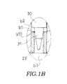
- the piston rod 2 includes a central hole b1 formed in an axial center portion so as to open onto the vehicle body side (the upper side in FIG. 1 ), a lateral hole b2 that connects the central hole b1 to the expansion side chamber r1, and a longitudinal hole b3 that connects the central hole b1 to the contraction side chamber r2.
- the bypass passage B that connects the pair of chambers r1, r2 so as to bypass the flow passages L1, L2 is constituted by the central hole b1, the lateral hole b2, and the longitudinal hole b3.
- an annular bush 23 disposed between a longitudinal hole side opening (reference symbol omitted) and a lateral hole side opening (reference symbol omitted) of the central hole b1 is held on an inner periphery of the piston rod 2.
- the variable throttle member 3 constituted by the push rod 30 and the needle valve 31 held on the tip end of the push rod 30 is inserted into the central hole b1 to be capable of moving in the axial direction.
- the variable throttle member 3 is disposed on the central axis of the shock absorber D such that a central axis x1 (see FIG. 2 ) of the variable throttle member 3 overlaps the central axis of the shock absorber D.
- the needle valve 31 of the variable throttle member 3 is inserted retractably into the bush 23. Accordingly, an annular gap flow passage b10 formed between the needle valve 31 and the bush 23 is widened and narrowed. As a result, the opening of the bypass passage B can be modified.
- a base end portion 30a positioned on an opposite side (a back surface side) to the needle valve 31 is formed to have a smaller diameter than a remaining part.
- An annular oil seal 24 held on the inner periphery of the piston rod 2 slides against an outer peripheral surface of the base end portion 30a of the push rod 30.
- the vehicle body side opening of the central hole b1 constituting the bypass passage B is blocked.
- a tip end of the base end portion 30a of the push rod 30 projects into a hollow portion 21a formed in the interior of the housing 21.
- the actuator 4 that drives the variable throttle member 3 is held in the housing 21.
- the power transmission mechanism 5 that transmits an action from the actuator 4 to the variable throttle member 3 is housed in the hollow portion 21a of the housing 21.
- the actuator 4 includes the motor 40, the acting portion 41 that acts on the power transmission mechanism 5, and the motion conversion mechanism (not shown) that converts the rotary motion of the motor 40 into the linear motion of the acting portion 41.
- Various well-known configurations such as similar configurations to those of the actuator 4 of the comparative example described above, for example, may be employed as the configurations of the motor 40 and the motion conversion mechanism (not shown) of the actuator 4. Hence, detailed description thereof has been omitted here.
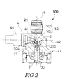
- the acting portion 41 of the actuator 4 projects into the hollow portion 21a of the housing 21. As shown in FIG. 2 , the actuator 4 is attached such that a central axis x2 of the acting portion 41 intersects the central axis x1 of the variable throttle valve 3 (an axial center line of the shock absorber D) substantially perpendicularly. By rotating the motor 40, the acting portion 41 of the actuator 4 can be caused to approach and retreat from the central axis x1 of the variable throttle member 3.
- the power transmission mechanism 5 is constituted by a rotary body 50 that rotates about a rotary shaft 50a upon reception of the linear motion of the acting portion 41 of the actuator 4.
- the rotary body 50 is formed in an L shape, and includes an input piece 50b and an output piece 50c.
- the rotary shaft 50a is provided in a part of the rotary body 50 where the input piece 50b and the output piece 50c intersect.
- an outside surface positioned on an opposite side (a left side in FIG. 2 ) to the output piece 50c contacts the acting portion 41 of the actuator 4.
- an outside surface positioned on an opposite side (a lower side in FIG. 2 ) to the input piece 50b contacts the push rod 30 of the variable throttle member 3.
- the rotary shaft 50a is disposed further toward the actuator 4 side than the central axis x1 of the variable throttle member 3.
- the rotary body 50 rotates in a direction of an arrow y1 (clockwise in FIG. 2 ). Accordingly, the output piece 50c rotates so as to push the variable throttle member 3 downward. Hence, the needle valve 31 of the variable throttle member 3 is caused to advance into the bush 23 so as to narrow the gap flow passage b10, and as a result, the opening of the bypass passage B can be reduced.
- the flow rate of the working fluid passing through the flow passages L1, L2 in the piston 7 therefore increases such that the damping force generated by the shock absorber D is adjusted in an increasing direction.
- variable throttle member 3 When the motor 40 causes the acting portion 41 to retreat from the central axis x1 of the variable throttle member 3, on the other hand, the variable throttle member 3 is pushed upward by a pressure in the contraction side chamber r2 such that the rotary body 50 rotates in an opposite direction to the arrow y1 (counterclockwise in FIG. 2 ). Hence, the needle valve 31 of the variable throttle member 3 is caused to retreat from the bush 23 so as to widen the gap flow passage b10, and as a result, the opening of the bypass passage B can be increased. The flow rate of the working fluid passing through the flow passages L1, L2 in the piston 7 therefore decreases such that the damping force generated by the shock absorber D is adjusted in a decreasing direction.
- the actuator 4 is connected to the vehicle body side of the suspension spring S via the housing 21. Further, the motor 40 is disposed on the spring of the suspension spring S. In the suspension apparatus 100, therefore, an impact input from the vehicle wheel side can be absorbed by the suspension spring S, with the result that direct input of the impact into the motor 40 can be suppressed.
- the actuator 4 includes the acting portion 41 that acts on the variable throttle member 3, and the motion conversion mechanism (not shown) that converts the rotary motion of the motor 40 into the linear motion of the acting portion 41.
- the actuator 4 is disposed such that the central axis x2 of the acting portion 41 intersects the central axis x1 of the variable throttle valve 3 substantially perpendicularly.
- the acting portion 41 and the variable throttle valve 3 are provided eccentrically.
- the suspension apparatus 100 includes the power transmission mechanism 5 interposed between the acting portion 41 and the variable throttle member 3. In the suspension apparatus 100, the power transmission mechanism 5 converts a direction of the linear motion of the acting portion 41 and transmits the linear motion to the variable throttle member 3.
- the actuator 4 can be disposed at a remove from the central axis of the shock absorber D.
- the vehicle body side attachment member 20 and the variable throttle member 3 can be provided close together even when the actuator 4 is disposed on the vehicle body side and the vehicle body side attachment member 20 and variable throttle member 3 are disposed along the central axis of the shock absorber D. As a result, an attachment dimension of the suspension apparatus 100 can be shortened.
- the power transmission mechanism 5 includes the rotary body 50 that rotates about the rotary shaft 50a upon reception of the linear motion of the acting portion 41 of the actuator 4. Therefore, the linear motion of the acting portion 41 can be transmitted to the variable throttle member 3 even when the variable throttle member 3 and the acting portion 41 are provided eccentrically such that the central axis x2 of the acting portion 41 does not overlap the central axis x1 of the variable throttle member 3.
- the rotary body 50 is formed in an L shape including the input piece 50b and the output piece 50c.
- the acting portion 41 of the actuator 4 contacts the outside surface of the input piece 50b.
- the outside surface of the output piece 50c contacts the variable throttle member 3.
- the rotary shaft 50a is provided in the part where the input piece 50b and the output piece 50c intersect.
- the rotary shaft 50a is disposed further toward the actuator 4 side (the left side in FIG. 2 ) than the central axis x1 of the variable throttle member 3.
- the power transmission mechanism 5 converts the direction of the linear motion of the acting portion 41 into a direction of a linear motion of the variable throttle member 3.
- an input from the actuator 4 can be transmitted to the variable throttle member 3 easily.
- the power transmission mechanism 5 is configured simply and can therefore be housed in a small space. Accordingly, the suspension apparatus 100 can be reduced in size.
- a ratio between a distance (referred to hereafter as a "distance d1") from a point of force at which an input from the actuator 4 is received to a fulcrum (the rotary shaft 50a) and a distance (referred to hereafter as a “distance d2”) from a point of application on the push rod 30 of the variable throttle member 3 to the fulcrum (the rotary shaft 50a) can be modified easily.
- a movement distance of the acting portion 41 and a movement distance of the variable throttle member 3 are equal, but the distance by which the variable throttle member 3 is moved is shorter than a movable distance (referred to hereafter as a "stroke length") of the acting portion 41. Therefore, the stroke length of the acting portion 41 in the actuator 4 cannot be utilized sufficiently.
- the stroke length of the acting portion 41 of the actuator 4 can be used effectively by reducing the distance d2 relative to the distance d1.
- the variable throttle member 3 can be driven using a smaller amount of force than in the comparative example.
- variable throttle member 3 includes the needle valve 31 inserted into the bypass passage B to be capable of advancing and retreating, and the push rod 30 interposed between the needle valve 31 and the power transmission mechanism 5.
- the base end portion 30a of the push rod 30, provided on the opposite side to the needle valve 31, is formed to have a smaller diameter than the remaining part.
- the variable throttle member 3 is pushed upward to the vehicle body side (the upper side in FIG. 1 ) by the pressure in the contraction side chamber r2, but by providing the power transmission mechanism 5, a force acting on the motor 40 can be reduced.
- the attachment dimension of the suspension apparatus 100 can be shortened easily even in a case where the actuator 4 is disposed on the vehicle body side such that the vehicle body side attachment member 20 and the variable throttle member 3 are disposed along the central axis of the shock absorber D, or a case where the actuator 4 is disposed on the vehicle wheel side such that the vehicle wheel side attachment member 10 and the variable throttle member 3 are disposed along the central axis of the shock absorber D.
- a suspension apparatus 200 according to a second embodiment of the present invention will be described below.
- configurations that are identical to the above embodiment have been allocated identical reference symbols, and duplicate description thereof has been omitted where appropriate.
- the suspension apparatus 200 according to the second embodiment differs from the first embodiment in the configuration of the power transmission mechanism and the arrangement of the actuator, but all other configurations, as well as actions and effects thereof, are identical to the first embodiment.
- the actuator 4 is disposed such that the central axis x2 of the acting portion 41 is substantially parallel to the central axis x1 of the variable throttle valve 3 (the axial center line of the shock absorber D).
- the acting portion 41 and the variable throttle member 3 are provided eccentrically.
- a power transmission mechanism 5A is constituted by a rotary body 51 that rotates about a rotary shaft 51a upon reception of the linear motion of the actuator 4.
- the rotary body 51 is constituted by a plate-shaped body disposed so as to intersect both the central axis x2 of the acting portion 41 and the central axis x1 of the variable throttle member 3.
- the acting portion 41 and the push rod 30 of the variable throttle member 3 respectively contact the rotary body 51.
- the rotary shaft 51a is provided in a positioned further removed from the actuator 4 than a contact position of the variable throttle member 3.
- the rotary shaft 51a, the variable throttle member 3, and the actuator 4 are arranged in a lateral direction in that order.
- the rotary body 51 rotates in a direction of an arrow y2 (counterclockwise in FIG. 3 ) so as to push the variable throttle member 3 downward.
- the needle valve 31 of the variable throttle member 3 is caused to advance into the bush 23 so as to narrow the gap flow passage b10, and as a result, the opening of the bypass passage B can be reduced.
- the flow rate of the working fluid passing through the flow passages L1, L2 in the piston 7 therefore increases such that the damping force generated by the shock absorber D is adjusted in the increasing direction.
- variable throttle member 3 When the motor 40 causes the acting portion 41 to move to the vehicle body side (an upper side in FIG. 3 ), on the other hand, the variable throttle member 3 is pushed upward by the pressure in the contraction side chamber r2 such that the rotary body 51 rotates in an opposite direction to the arrow y2 (clockwise in FIG. 3 ). Hence, the needle valve 31 of the variable throttle member 3 is caused to retreat from the bush 23 so as to widen the gap flow passage b10, and as a result, the opening of the bypass passage B can be increased. The flow rate of the working fluid passing through the flow passages L1, L2 in the piston 7 therefore decreases such that the damping force generated by the shock absorber D is adjusted in the decreasing direction.
- the central axis x2 of the acting portion 41 and the central axis x1 of the variable throttle member 3 are disposed to be substantially parallel. Further, the acting portion 41 and the variable throttle member 3 are provided eccentrically.
- the suspension apparatus 200 includes the power transmission mechanism 5A interposed between the acting portion 41 and the variable throttle member 3. The power transmission mechanism 5A transmits the linear motion of the acting portion 41 to the variable throttle member 3.
- the actuator 4 can be disposed at a remove from the central axis of the shock absorber D.
- the vehicle body side attachment member 20 and the variable throttle member 3 can be provided close together even when the actuator 4 is disposed on the vehicle body side and the vehicle body side attachment member 20 and variable throttle member 3 are disposed along the central axis of the shock absorber D. As a result, the attachment dimension of the suspension apparatus 200 can be shortened easily.
- the power transmission mechanism 5A includes the rotary body 51 that rotates about the rotary shaft 51a upon reception of the linear motion of the acting portion 41 of the actuator 4. Similarly to the first embodiment, therefore, the linear motion of the acting portion 41 can be transmitted easily to the variable throttle member 3 even when the variable throttle member 3 and the acting portion 41 are provided eccentrically such that the central axis x2 of the acting portion 41 and the central axis x1 of the variable throttle member 3 do not overlap.
- the rotary body 51 is constituted by the plate-shaped body disposed so as to intersect both the central axis x2 of the acting portion 41 and the central axis x1 of the variable throttle member 3.
- the acting portion 41 contacts a surface (an upper surface in FIG. 3 ) on an opposite side to the cylinder 1.
- the variable throttle member 3 contacts a surface (a lower surface in FIG. 3 ) on the cylinder 1 side.
- the rotary shaft 51a is provided in a position (on a right side in FIG. 3 ) further removed from the actuator 4 than the variable throttle member 3.
- the linear motion of the acting portion 41 can be transmitted easily to the variable throttle member 3 by having the rotary body 51 rotate upon reception of the linear motion of the acting portion 41.
- the power transmission mechanism 5A is configured simply and can therefore be housed in a small space, enabling a reduction in the size of the suspension apparatus 200.
- a ratio between a distance (referred to hereafter as a "distance d3") from a point of force at which an input from the actuator 4 is received to a fulcrum (the rotary shaft 51a) and a distance (referred to hereafter as a “distance d4") from a point of application on the push rod 30 of the variable throttle member 3 to the fulcrum (the rotary shaft 51a) can be modified easily.
- the stroke length of the acting portion 41 in the actuator 4 cannot be utilized sufficiently.
- the distance d4 is shorter than the distance d3, and therefore the stroke length of the acting portion 41 of the actuator 4 can be used effectively.
- the variable throttle member 3 can be driven using a smaller amount of force than in the comparative example.
- the suspension apparatus 300 according to the third embodiment differs from the first embodiment in the configuration of the power transmission mechanism and a shape of the acting portion of the actuator, but all other configurations, as well as actions and effects thereof, are identical to the first embodiment.
- the acting portion 41 of the actuator 4 includes an extension piece 41a that extends along the central axis x2 of the acting portion 41 toward the central axis x1 of the variable throttle member 3.
- a power transmission mechanism 5B includes a rotary body 52 that rotates about a rotary shaft 52a upon reception of the linear motion of the acting portion 41 of the actuator 4, and a biasing spring 53 that biases the rotary body 52 in a direction for causing the rotary body 52 to rotate on the actuator side.
- the rotary body 52 includes an output portion 52c formed with a curved surface on one side so as to have a fan-shaped cross-section, and an input portion 52b that stands upright from an opposite side to the curved surface of the output portion 52c.
- the extension piece 41a of the acting portion 41 contacts a side face of the input portion 52b.
- the curved surface of the output portion 52c contacts the push rod 30 of the variable throttle member 3.
- the rotary shaft 52a is provided on the curved surface side of the output portion 52c.
- the rotary shaft 52a is disposed on the central axis x1 of the variable throttle member 3.
- the biasing spring 53 contacts a side face of the input portion 52b on an opposite side to the actuator 4.
- the push rod 30 is set to contact a position of the curved surface that is closest to the rotary shaft 52a.
- the rotary body 52 is caused to rotate in an opposite direction to the arrow y3 (counterclockwise in FIG. 4 ) by a biasing force of the biasing spring 53 such that the position in which the rotary body 52 is contacted by the push rod 30 approaches the rotary shaft 52a.
- the variable throttle member 3 is pushed upward by the pressure in the contraction side chamber r2.
- the needle valve 31 of the variable throttle member 3 is caused to retreat from the bush 23 so as to widen the gap flow passage b10, and as a result, the opening of the bypass passage B can be increased.
- the flow rate of the working fluid passing through the flow passages L1, L2 formed in the piston 7 therefore decreases, with the result that the damping force generated by the shock absorber D is adjusted in the decreasing direction.
- the actuator 4 is disposed such that the central axis x2 of the acting portion 41 intersects the central axis x1 of the variable throttle valve 3 substantially perpendicularly. Further, the acting portion 41 and the variable throttle valve 3 are provided eccentrically.
- the suspension apparatus 300 includes the power transmission mechanism 5B interposed between the acting portion 41 and the variable throttle member 3. The power transmission mechanism 5B converts the direction of the linear motion of the acting portion 41 and transmits the linear motion to the variable throttle member 3.
- the actuator 4 can be disposed at a remove from the central axis of the shock absorber D.
- the vehicle body side attachment member 20 and the variable throttle member 3 can be provided close together even when the actuator 4 is disposed on the vehicle body side and the vehicle body side attachment member 20 and variable throttle member 3 are disposed along the central axis of the shock absorber D. As a result, the attachment dimension of the suspension apparatus 300 can be shortened easily.
- the power transmission mechanism 5B includes the rotary body 52 that rotates about the rotary shaft 52a upon reception of the linear motion of the acting portion 41 of the actuator 4. Similarly to the first embodiment, therefore, the linear motion of the acting portion 41 can be transmitted easily to the variable throttle member 3 even when the variable throttle member 3 and the acting portion 41 are provided eccentrically such that the central axis x2 of the acting portion 41 and the central axis x1 of the variable throttle member 3 do not overlap.
- the power transmission mechanism 5B includes the rotary body 52 and the biasing spring 53 that biases the rotary body 52 in the direction for causing the rotary body 52 to rotate on the actuator 4 side.
- the rotary body 52 includes the output portion 52c formed with a curved surface on one side so as to have a fan-shaped cross-section, and the input portion 52b that stands upright from the opposite side to the curved surface of the output portion 52c.
- the acting portion 41 contacts the side face of the input portion 52b.
- the variable throttle member 3 contacts the curved surface of the output portion 52c.
- the rotary shaft 52a is provided on the curved surface side of the output portion 52c and disposed on the central axis x1 of the variable throttle member 3.
- the biasing spring 53 contacts the side face of the input portion 52b on the opposite side to the actuator 4.
- the power transmission mechanism 5B can easily convert the direction of the linear motion of the acting portion 41 into the direction of the linear motion of the variable throttle member 3 and transmit the linear motion easily to the variable throttle member 3. Furthermore, the power transmission mechanism 5B is configured simply and can therefore be housed in a small space, enabling a reduction in the size of the suspension apparatus 300.
- a distance (referred to hereafter as a "distance d6" by which the variable throttle member 3 is moved by the rotation of the rotary body 52 can easily be made shorter than a distance (referred to hereafter as a “distance d5") by which the acting portion 41 moves in order to rotate the rotary body 52.
- the stroke length of the acting portion 41 in the actuator 4 cannot be utilized sufficiently.
- the distance d4 is shorter than the distance d5, and therefore the stroke length of the acting portion 41 of the actuator 4 can be used effectively.
- the variable throttle member 3 can be driven using a smaller amount of force than in the comparative example.
- the suspension apparatus 400 according to the fourth embodiment differs from the first embodiment in the configuration of the power transmission mechanism, but all other configurations, as well as actions and effects thereof, are identical to the first embodiment.
- a power transmission mechanism 5C includes a first movable wall 54 capable of moving in an identical direction to the acting portion 41 as the acting portion 41 moves, a second movable wall 55 capable of moving in an identical direction to the variable throttle member 3 as the variable throttle member 3 moves, and a fluid retention chamber 56 formed between the first movable wall 54 and the second movable wall 55.
- the fluid retention chamber 56 includes a first chamber 56a into which the first movable wall 54 is inserted to be capable of advancing and retreating, and a second chamber 56b which communicates with the first chamber 56a and into which the second movable wall 55 is inserted to be capable of advancing and retreating.
- a fluid constituted by a liquid or a gas is charged into an interior of the fluid retention chamber 56.
- An identical fluid or a different fluid to the working fluid housed in the cylinder 1 may be used as the fluid.
- the first movable wall 54 moves in an identical direction. Accordingly, the fluid in the first chamber 56a moves into the second chamber 56b such that the second movable wall 55 and the variable throttle member 3 are pushed downward in the axial direction (a downward direction in FIG. 5 ).
- the needle valve 31 of the variable throttle member 3 is caused to advance into the bush 23 so as to narrow the gap flow passage b10, and as a result, the opening of the bypass passage B can be reduced.
- the flow rate of the working fluid passing through the flow passages L1, L2 in the piston 7 therefore increases such that the damping force generated by the shock absorber D is adjusted in the increasing direction.
- variable throttle member 3 and the second movable wall 55 are pushed upward in the axial direction (an upward direction in FIG. 5 ) by the pressure in the contraction side chamber r2.
- the fluid in the second chamber 56b moves into the first chamber 56a such that the first movable wall 54 moves to the actuator 4 side (a left side in FIG. 5 ).
- the needle valve 31 of the variable throttle member 3 is caused to retreat from the bush 23 so as to widen the gap flow passage b10, and as a result, the opening of the bypass passage B can be increased.
- the flow rate of the working fluid passing through the flow passages L1, L2 in the piston 7 therefore decreases such that the damping force generated by the shock absorber D is adjusted in the decreasing direction.
- the actuator 4 is disposed such that the central axis x2 of the acting portion 41 intersects the central axis x1 of the variable throttle valve 3 substantially perpendicularly. Further, the acting portion 41 and the variable throttle valve 3 are provided eccentrically.
- the suspension apparatus 400 includes the power transmission mechanism 5C interposed between the acting portion 41 and the variable throttle member 3. The power transmission mechanism 5C converts the direction of the linear motion of the acting portion 41 and transmits the linear motion to the variable throttle member 3.
- the actuator 4 can be disposed at a remove from the central axis of the shock absorber D.
- the vehicle body side attachment member 20 and the variable throttle member 3 can be provided close together even when the actuator 4 is disposed on the vehicle body side and the vehicle body side attachment member 20 and variable throttle member 3 are disposed along the central axis of the shock absorber. As a result, the attachment dimension of the suspension apparatus 400 can be shortened easily.
- the power transmission mechanism 5C includes the first movable wall 54 that is capable of moving in an identical direction to the acting portion 41 as the acting portion 41 moves, the second movable wall 55 that is capable of moving in an identical direction to the variable throttle member 3 as the variable throttle member 3 moves, and the fluid retention chamber 56 formed between the first movable wall 54 and the second movable wall 55.
- the fluid retention chamber 56 includes the first chamber 56a into which the first movable wall 54 is inserted to be capable of advancing and retreating, and the second chamber 56b which communicates with the first chamber 56a and into which the second movable wall 55 is inserted to be capable of advancing and retreating. A fluid is charged into the interior of the fluid retention chamber 56.
- the power transmission mechanism 5C can easily convert the direction of the linear motion of the acting portion 41 into the direction of the linear motion of the variable throttle member 3 and transmit the linear motion easily to the variable throttle member 3. Furthermore, the power transmission mechanism 5C is configured simply and can therefore be housed in a small space, enabling a reduction in the size of the suspension apparatus 400.
- the second movable wall 55 is formed to have a larger outer diameter than the first movable wall 54.
- the second chamber 56b is formed to have a larger sectional area than the first chamber 56a. Therefore, a distance (referred to hereafter as a “distance d8") by which the variable throttle member 3 moves together with the second movable wall 55 can easily be made shorter than a distance (referred to hereafter as a “distance d7”) by which the first movable wall 54 moves together with the acting portion 41.
- the stroke length of the acting portion 41 in the actuator 4 cannot be utilized sufficiently.
- the distance d8 is shorter than the distance d7, and therefore the stroke length of the acting portion 41 of the actuator 4 can be used effectively.
- the variable throttle member 3 can be driven using a smaller amount of force than in the comparative example.
- the suspension apparatus 500 according to the fifth embodiment differs from the first embodiment in the configuration of the power transmission mechanism, but all other configurations, as well as actions and effects thereof, are identical to the first embodiment.
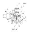
- a power transmission mechanism 5D is constituted by a columnar body 57 that is connected to the acting portion 41 to be capable of moving while intersecting the central axis x1 of the variable throttle member 3.
- the columnar body 57 includes a pair of bearing portions 57a, 57b disposed on respective ends thereof so as to slide against the inner peripheral surface of the housing 21, and a conical portion 57c that is disposed between the bearing portions 57a, 57b and decreases gradually in diameter from the actuator 4 side toward the opposite side to the actuator 4.
- the push rod 30 of the variable throttle member 3 contacts an outer peripheral surface of the conical portion 57c.
- the columnar body 57 moves in an identical direction.
- the conical portion 57c contacted by the push rod 30 increases in diameter such that the variable throttle member 3 is pushed downward in the axial direction (a downward direction in FIG. 6 ).
- the needle valve 31 of the variable throttle member 3 is caused to advance into the bush 23 so as to narrow the gap flow passage b10, and as a result, the opening of the bypass passage B can be reduced.
- the flow rate of the working fluid passing through the flow passages L1, L2 in the piston 7 therefore increases such that the damping force generated by the shock absorber D is adjusted in the increasing direction.
- the motor 40 causes the acting portion 41 to move away from the central axis x1 of the variable throttle member 3, the columnar body 57 moves in an identical direction.
- the conical portion 57c contacted by the push rod 30 decreases in diameter such that the variable throttle member 3 is pushed upward in the axial direction (an upward direction in FIG. 6 ) by the pressure in the contraction side chamber r2.
- the needle valve 31 of the variable throttle member 3 is caused to retreat from the bush 23 so as to widen the gap flow passage b10, and as a result, the opening of the bypass passage B can be increased.
- the flow rate of the working fluid passing through the flow passages L1, L2 in the piston 7 therefore decreases such that the damping force generated by the shock absorber D is adjusted in the decreasing direction.
- the actuator 4 is disposed such that the central axis x2 of the acting portion 41 intersects the central axis x1 of the variable throttle valve 3 substantially perpendicularly. Further, the acting portion 41 and the variable throttle valve 3 are provided eccentrically.
- the suspension apparatus 500 includes the power transmission mechanism 5D interposed between the acting portion 41 and the variable throttle member 3. The power transmission mechanism 5D converts the direction of the linear motion of the acting portion 41 and transmits the linear motion to the variable throttle member 3.
- the actuator 4 can be disposed at a remove from the central axis of the shock absorber D.
- the vehicle body side attachment member 20 and the variable throttle member 3 can be provided close together even when the actuator 4 is disposed on the vehicle body side and the vehicle body side attachment member 20 and variable throttle member 3 are disposed along the central axis of the shock absorber D. As a result, the attachment dimension of the suspension apparatus 500 can be shortened easily.
- the power transmission mechanism 5D is constituted by the columnar body 57 connected to the acting portion 41 to be capable of moving while intersecting the central axis x1 of the variable throttle member 3.
- the columnar body 57 includes the conical portion 57c that decreases gradually in diameter from the actuator 4 side toward the opposite side to the actuator 4.
- the variable throttle member 3 contacts the outer peripheral surface of the conical portion 57c.
- the power transmission mechanism 5D can easily convert the direction of the linear motion of the acting portion 41 into the direction of the linear motion of the variable throttle member 3 and transmit the linear motion easily to the variable throttle member 3.
- the power transmission mechanism 5D is configured simply and can therefore be housed in a small space, enabling a reduction in the size of the suspension apparatus 500.
- a distance (referred to hereafter as a “distance d10") by which the variable throttle member 3 is moved by the movement of the columnar body 57 can easily be made shorter than a distance (referred to hereafter as a “distance d9") by which the acting portion 41 moves in order to move the columnar body 57.
- the stroke length of the acting portion 41 in the actuator 4 cannot be utilized sufficiently.
- the distance d10 is shorter than the distance d9, and therefore the stroke length of the acting portion 41 of the actuator 4 can be used effectively.
- the variable throttle member 3 can be driven using a smaller amount of force than in the comparative example.
- the suspension apparatus 100, 200, 300, 400, 500 is a rear cushion unit, but may be a front fork that suspends a front wheel of a motorcycle or a suspension apparatus for a transportation device other than a motorcycle, such as an automobile.
- the shock absorber D is an upright type shock absorber in which the piston rod 2 is connected to the vehicle body side via the vehicle body side attachment member 20 and the cylinder 1 is connected to the vehicle wheel side via the vehicle wheel side attachment member 10.
- the present invention is not limited thereto, however, and the shock absorber D may be an inverted type shock absorber in which the piston 1 is connected to the vehicle body side via a vehicle body side attachment member and the piston rod 2 is attached to the vehicle wheel side via a vehicle wheel side attachment member.
- the variable throttle member 3, the actuator 4, and the vehicle wheel side attachment member along the central axis of the shock absorber D.
- the attachment dimension of the suspension apparatus can be shortened easily even when the actuator 4 is disposed on the vehicle wheel side and the vehicle wheel side attachment member and variable throttle member 3 are disposed along the central axis of the shock absorber D.
- the shock absorber D is a single tube type shock absorber having the free piston 6 that is capable of moving through the cylinder 1 in the axial direction and the air chamber A that is defined by the free piston 6 to be capable of swelling and contracting. Therefore, volume compensation and temperature compensation can be performed by the air chamber A.
- the shock absorber D may be a multiple tube type shock absorber having an outer tube disposed on an outer periphery of the cylinder 1, a reservoir formed between the outer tube and the cylinder 1 in order to house a working fluid, a base member fixed to the cylinder 1 in order to separate the reservoir from the contraction side chamber r2, another flow passage formed in the base member to connect the reservoir to the contraction side chamber, and another damping force generation mechanism that applies resistance to the working fluid passing through the other flow passage.
- volume compensation and temperature compensation are performed by the reservoir.
- a bypass passage may be provided to connect the reservoir to the contraction side chamber r2 so as to bypass the other flow passage formed in the base member (not shown), and the damping force generated by the shock absorber may be adjusted by modifying an opening of the bypass passage using the variable throttle member 3.
- the configuration of the power transmission mechanism 5, 5A, 5B, 5C, 5D is not limited to those described above, and any configuration may be selected appropriately as long as the linear motion of the acting portion 41 disposed eccentrically relative to the variable throttle member 3 can be transmitted to the variable throttle member 3.
- an auxiliary spring (not shown) may be added to the power transmission mechanism 5, 5A, 5B to bias the rotary body 50, 51, 52 in a direction for causing the rotary body 50, 51, 52 to rotate on the opposite side to the actuator (the side of the arrow y1, y2, y3).
- advancement of the variable throttle member 3 into the bypass passage 3 is assisted by the auxiliary spring, and therefore a load exerted on the motor 40 can be lightened.
Landscapes
- Engineering & Computer Science (AREA)
- Mechanical Engineering (AREA)
- General Engineering & Computer Science (AREA)
- Vehicle Body Suspensions (AREA)
- Fluid-Damping Devices (AREA)
- Axle Suspensions And Sidecars For Cycles (AREA)
Abstract

Description
- The present invention relates to an improvement in a suspension apparatus.
- Typically, in a transportation device such as an automobile or a motorcycle, a suspension apparatus is interposed between a vehicle body and a vehicle wheel in order to suppress transmission of an impact generated by irregularities on a road surface or the like to the vehicle body.
-
JP2011-117493A - The shock absorber includes a pair of chambers defined by a piston within a cylinder, a flow passage formed in the piston to connect the pair of chambers in the cylinder, and damping force generating means for applying resistance to a working fluid passing through the flow passage. The shock absorber includes a bypass passage that connects the pair of chambers in the cylinder so as to bypass the flow passage in which the damping force generating means is provided, a variable throttle member that is inserted into the bypass passage to be capable of advancing and retreating in order to modify an opening of the bypass passage, and an actuator that drives the variable throttle member.
- Here, when the suspension apparatus is used as a rear cushion unit that suspends a rear wheel of a motorcycle, for example, a vehicle body side attachment member for connecting the shock absorber to the vehicle body side is preferably provided on a central axis of the shock absorber. In this case, the variable throttle member, the actuator, and the vehicle body side attachment member are arranged longitudinally along the central axis of the shock absorber.
- However, in this case, the variable throttle member and the vehicle body side attachment member are removed from each other, leading to an increase in a distance between a vehicle wheel side attachment member for connecting the shock absorber to the vehicle wheel side and the vehicle body side attachment member. Hence, an attachment dimension of the suspension apparatus lengthens, and as a result, a stroke length of the suspension apparatus may be restricted.
- Further, when the shock absorber is set in an inverted orientation such that the actuator is disposed on the vehicle wheel side, the variable throttle member, the actuator, and the vehicle wheel side attachment member are arranged longitudinally along the central axis of the shock absorber. Likewise in this case, therefore, the attachment dimension of the suspension apparatus lengthens, and as a result, the stroke length of the suspension apparatus may be restricted.
- The present invention has been designed in consideration of the problems described above, and an object thereof is to shorten an attachment dimension of a suspension apparatus even in a case where an actuator is disposed on a vehicle body side such that a vehicle body side attachment member and a variable throttle member are disposed along a central axis of a shock absorber, or a case in which the actuator is disposed on a vehicle wheel side such that a vehicle wheel side attachment member and the variable throttle member are disposed along the central axis of the shock absorber.
- According to one aspect of the present invention, a suspension apparatus interposed between a vehicle body and a vehicle wheel is provided. The suspension apparatus includes a shock absorber having a cylinder and a piston rod inserted retractably into the cylinder and a biasing member that biases the shock absorber in an expansion direction. The shock absorber includes a pair of chambers housing a working fluid, a flow passage that connects the pair of chambers such that the working fluid passes through the flow passage as the shock absorber expands and contracts, a damping force generation mechanism that is configured to apply resistance to the working fluid passing through the flow passage, a bypass passage that connects the pair of chambers so as to bypass the flow passage, a variable throttle member that is inserted into the bypass passage to be capable of advancing and retreating in order to modify an opening of the bypass passage, an actuator that is configured to drive the variable throttle member, and includes a motor, an acting portion disposed on a back surface side of the variable throttle member and provided eccentrically relative to the variable throttle member, and a motion conversion mechanism that is configured to convert a rotary motion of the motor into a linear motion of the acting portion, and a power transmission mechanism interposed between the acting portion and the variable throttle member in order to transmit the linear motion of the acting portion to the variable throttle member.
- The details as well as other features and advantages of the present invention are set forth in the remainder of the specification and are shown in the accompanying drawings.
-
-
FIG. 1A is a longitudinal sectional view showing a suspension apparatus according to a first embodiment of the present invention. -
FIG. 1B is an enlarged view of an IB portion ofFIG. 1A . -
FIG. 2 is a view showing an enlargement of a vehicle body side part ofFIG. 1A . -
FIG. 3 is a longitudinal sectional view showing an enlargement of a vehicle body side part of a suspension apparatus according to a second embodiment of the present invention. -
FIG. 4 is a longitudinal sectional view showing an enlargement of a vehicle body side part of a suspension apparatus according to a third embodiment of the present invention. -
FIG. 5 is a longitudinal sectional view showing an enlargement of a vehicle body side part of a suspension apparatus according to a fourth embodiment of the present invention. -
FIG. 6 is a longitudinal sectional view showing an enlargement of a vehicle body side part of a suspension apparatus according to a fifth embodiment of the present invention. -
FIG. 7 is a longitudinal sectional view showing a suspension apparatus according to a comparative example of the present invention. -
FIG. 8 is a longitudinal sectional view showing an enlargement of a vehicle body side part of the suspension apparatus according to the comparative example of the present invention in a case where a vehicle body side attachment member is provided on a central axis of a shock absorber. - A
suspension apparatus 100 according to a first embodiment of the present invention will be described below with reference to the figures. Identical reference symbols used over a plurality of figures denote identical or corresponding components. - First, to facilitate understanding of the
suspension apparatus 100, asuspension apparatus 600 according to a comparative example of the present invention will be described with reference toFIGS. 7 and8 . - The
suspension apparatus 600 is a front fork suspending a front wheel of a motorcycle. As shown inFIG. 7 , thesuspension apparatus 600 includes a suspension apparatus main body T constituted by an outer tube t1 connected to a vehicle body side, and an inner tube t2 connected to a vehicle wheel side and inserted retractably into the outer tube t1. A shock absorber D and a suspension spring (a biasing member) S are housed in parallel inside the suspension apparatus main body T. - The shock absorber D includes a
cylinder 1 connected to the vehicle wheel side, apiston rod 2 connected to the vehicle body side and inserted retractably into thecylinder 1, and apiston 7 held by thepiston rod 2 so as to slide against an inner peripheral surface of thecylinder 1. The suspension spring S is interposed between a vehicle body side spring bearing s2 fixed to thepiston rod 2 side and a vehicle wheel side spring bearing s1 fixed to thecylinder 1 side. The suspension spring S biases the shock absorber D in an expansion direction at all times. - The shock absorber D includes a pair of chambers r1, r2 formed so as to be defined by the
piston 7 within thecylinder 1 and filled with a working fluid, flow passages L1, L2 formed in thepiston 7 to connect the pair of chambers r1, r2, and damping force generation mechanisms V3, V4 that apply resistance to working fluid passing through the flow passages L1, L2. - When the
piston rod 2 advances and retracts within thecylinder 1 such that thesuspension apparatus 600 expands and contracts, the working fluid in one chamber r1 (r2) that is pressurized by thepiston 7 moves into the other chamber r2 (r1) through the flow passage L1 (L2). As a result, the shock absorber D can generate a damping force resulting from the resistance applied by the damping force generation mechanisms V3, V4. - The shock absorber D includes a bypass passage B that connects the pair of chambers r1, r2 so as to bypass the flow passages L1, L2, a
variable throttle member 3 that is inserted into the bypass passage B to be capable of advancing and retreating in order to modify an opening of the bypass passage B, and anactuator 4 that drives thevariable throttle member 3. - The
variable throttle member 3 includes aneedle valve 31 inserted into the bypass passage B to be capable of advancing and retreating, and apush rod 30 interposed between theneedle valve 31 and theactuator 4. Theactuator 4 is attached to acap member 25 that holds thepiston rod 2. Theactuator 4 includes amotor 40, anacting portion 41 that contacts a back surface of thepush rod 30, and amotion conversion mechanism 42 that converts a rotary motion of themotor 40 into a linear motion of theacting portion 41. - In the
suspension apparatus 600 configured as described above, a flow rate of the working fluid passing through the flow passages L1, L2 in which the damping force generation mechanisms V3, V4 are provided can be modified by driving thevariable throttle member 3 using theactuator 4 to modify the opening of the bypass passage B. According to thesuspension apparatus 600, therefore, the damping force generated by the shock absorber D can be adjusted. - In the
suspension apparatus 600, themotor 40 is disposed on a spring of the suspension spring S. Hence, in thesuspension apparatus 600, an impact input from the vehicle wheel side can be absorbed by the suspension spring S, with the result that direct input of the impact into themotor 40 can be suppressed. - Here, when the
suspension apparatus 600 is applied to a rear cushion unit that suspends a rear wheel of a motorcycle, for example, a vehicle body side attachment member for connecting the shock absorber D to the vehicle body side is preferably provided on a central axis of the shock absorber D. In this case, as shown inFIG. 8 , thevariable throttle member 3, theactuator 4, and a vehicle bodyside attachment member 20 are arranged longitudinally along a central axis z of the shock absorber D. - However, in this case, the
variable throttle member 3 and the vehicle bodyside attachment member 20 are removed from each other such that a distance between a vehicle wheel side attachment member (not shown) for connecting the shock absorber D to the vehicle wheel side and the vehicle bodyside attachment member 20 increases. Accordingly, an attachment dimension of thesuspension apparatus 600 lengthens, and as a result, a stroke length of thesuspension apparatus 600 may be restricted. - Further, although not shown in the figures, when the shock absorber D is set in an inverted orientation such that the
actuator 4 is disposed on the vehicle wheel side, thevariable throttle member 3, theactuator 4, and the vehicle wheel side attachment member are arranged longitudinally along the central axis z of the shock absorber D. Likewise in this case, therefore, the attachment dimension of thesuspension apparatus 600 lengthens, and as a result, the stroke length of thesuspension apparatus 600 may be restricted. - Next, referring to
FIGS. 1A to 2 , a configuration of thesuspension apparatus 100 will be described. - The
suspension apparatus 100 is interposed between a vehicle body and a vehicle wheel. As shown inFIG. 1 , thesuspension apparatus 100 includes the shock absorber D having thecylinder 1 and thepiston rod 2 inserted retractably into thecylinder 1, and the suspension spring S serving as a biasing member that biases the shock absorber D in the expansion direction at all times. - The shock absorber D includes the pair of chambers r1, r2 in which the working fluid is housed, the flow passages L1, L2 that connect the pair of chambers r1, r2 so that the working fluid passes through the flow passages L1, L2 as the shock absorber D expands and contracts, the damping force generation mechanisms (an expansion side damping valve V1 and a contraction side damping valve V2) that apply resistance to the working fluid passing through the flow passages L1, L2, the bypass passage B that connects the pair of chambers r1, r2 so as to bypass the flow passages L1, L2, the
variable throttle member 3 that is inserted into the bypass passage B to be capable of advancing and retreating in order to modify the opening of the bypass passage B, and theactuator 4 that drives thevariable throttle member 3. - The
actuator 4 includes themotor 40, theacting portion 41 disposed on a back surface side of thevariable throttle member 3, and the motion conversion mechanism (not shown) that converts the rotary motion of themotor 40 into the linear motion of theacting portion 41. Theacting portion 41 and thevariable throttle member 3 are provided eccentrically. The shock absorber D includes apower transmission mechanism 5 that is interposed between the actingportion 41 and thevariable throttle member 3 in order to transmit the linear motion of the actingportion 41 to thevariable throttle member 3. - The
suspension apparatus 100 will now be described in further detail. Thesuspension apparatus 100 is a rear cushion unit that suspends a rear wheel of a motorcycle, a three-wheeled vehicle, or the like. Although not shown in the figures, thesuspension apparatus 100 is interposed between the vehicle body and a swing arm that supports the rear wheel swingably. Thecylinder 1 of the shock absorber D is connected to the swing arm via a vehicle wheelside attachment member 10. Thepiston rod 2 of the shock absorber D is connected to a frame serving as a skeleton of the vehicle body via the vehicle bodyside attachment member 20. - The vehicle body
side attachment member 20 is attached to ahousing 21 connected to abase end portion 2a of thepiston rod 2 projecting from thecylinder 1. The vehicle bodyside attachment member 20 is disposed on the central axis of the shock absorber D. Atubular spring guide 22 is held vertically on thepiston rod 2 side (a lower side inFIG. 1 ) of thehousing 21. Thepiston rod 2 is inserted into thespring guide 22. - The vehicle body side spring bearing s2 is attached to an outer periphery of the
spring guide 22 to be capable of moving in an axial direction. The vehicle wheel side spring bearing s1 is fixed to a vehicle wheel side end portion outer periphery of thecylinder 1. The suspension spring S that biases the shock absorber D in the expansion direction at all times is interposed between the vehicle wheel side spring bearing s1 and the vehicle body side spring bearing s2. - A vehicle body side end portion of the suspension spring S is supported by the movable vehicle body side spring bearing s2. A fluid constituted by a liquid or a gas is supplied to and discharged from a jack chamber J formed on an opposite side (an upper side in
FIG. 1 ) of the vehicle body side spring bearing s2 to the suspension spring S. By moving the vehicle body side spring bearing s2 in the axial direction (an up-down direction inFIG. 1 ), a vehicle height and a spring reaction force of the suspension spring S can be adjusted. - The present invention is not limited to the configuration described above, and a configuration for holding the suspension spring S may be selected appropriately. For example, the vehicle wheel side spring bearing s1 may be made movable and the vehicle body side spring bearing s2 may be fixed. Further, both the vehicle wheel side spring bearing s1 and the vehicle body side spring bearing s2 may be fixed.
- The
cylinder 1 is formed in a closed-end tubular shape. A vehicle body side (the upper side inFIG. 1 ) opening of thecylinder 1 is closed by anannular rod guide 11. Further, the shock absorber D includes afree piston 6 that is capable of moving in the axial direction so as to slide against a vehicle wheel side inner peripheral surface of thecylinder 1. A fluid chamber R and an air chamber A are defined within thecylinder 1 by thefree piston 6. A working fluid constituted by oil, water, or a liquid such as an aqueous solution is charged into the fluid chamber R disposed on therod guide 11 side (the upper side inFIG. 1 ) of thefree piston 6. A gas is sealed into the air chamber A disposed on an opposite side (the lower side inFIG. 1 ) of therod guide 11. - A tubular bearing 12 that supports the
piston rod 2 to be free to move in the axial direction is fitted to an inner periphery of therod guide 11. Thepiston rod 2 is supported on therod guide 11 via thebearing 12. A tip end side of thepiston rod 2 advances into and retracts from the fluid chamber R. Anannular dust seal 13 is laminated to an outside air side (the upper side inFIG. 1 ) of therod guide 11. Anannular oil seal 14 is held on the fluid chamber R side (the lower side inFIG. 1 ) of therod guide 11. - Thus, foreign matter adhered to an outer peripheral surface of the
piston rod 2 can be brushed away by thedust seal 13 and thereby prevented from entering thecylinder 1. Further, working fluid adhered to the outer peripheral surface of thepiston rod 2 can be brushed away by theoil seal 14, whereby the working fluid in thecylinder 1 can be prevented from flowing out to the exterior. - The
annular piston 7 that slides against the inner peripheral surface of thecylinder 1 is held on an outer periphery of the tip end side of thepiston rod 2. Thepiston 7 divides the fluid chamber R formed in thecylinder 1 into the pair of chambers r1, r2. Hereafter, a chamber formed on thepiston rod 2 side (the upper side inFIG. 1 ) will be described as an expansion side chamber r1, and a chamber formed on the opposite side (the lower side inFIG. 1 ) to thepiston rod 2 will be described as a contraction side chamber r2. - The pair of flow passages L1, L2 connecting the expansion side chamber r1 to the contraction side chamber r2 are formed in the
piston 7. The expansion side damping valve V1 that applies resistance to the working fluid passing through the expansion side flow passage L1 by blocking an outlet of the expansion side flow passage L1 openably is laminated to thefree piston 6 side (the lower side inFIG. 1 ) of thepiston 7. Meanwhile, the contraction side damping valve V2 that applies resistance to the working fluid passing through the contraction side flow passage L2 by blocking an outlet of the contraction side flow passage L2 openably is laminated to therod guide 11 side (the upper side inFIG. 1 ) of thepiston 7. - The damping force generation mechanism that applies resistance to the working fluid passing through the flow passages L1, L2 that connect the pair of chambers r1, r2 is constituted by the expansion side damping valve V1 and the contraction side damping valve V2. Alternatively, the damping force generation mechanism may be formed using various other well-known configurations employing an orifice or the like.
- When the
piston rod 2 retreats from thecylinder 1 such that the shock absorber D configured as described above expands, the working fluid in the expansion side chamber r1, which is pressurized by thepiston 7, opens the expansion side damping valve V1 so as to move into the contraction side chamber r2 through the expansion side flow passage L1. As a result, the shock absorber D can generate an expansion side damping force resulting from the resistance applied by the expansion side damping valve V1. - When, on the other hand, the
piston rod 2 advances into thecylinder 1 such that the shock absorber D contracts, the working fluid in the contraction side chamber r2, which is pressurized by thepiston 7, opens the contraction side damping valve V2 so as to move into the expansion side chamber r1 through the contraction side flow passage L2. As a result, the shock absorber D can generate a contraction side damping force resulting from the resistance applied by the contraction side damping valve V2. - During expansion and contraction of the shock absorber D, an interior volume of the
cylinder 1 increases and decreases in accordance with a volume by which thepiston rod 2 advances into and retracts from thecylinder 1. At this time, thefree piston 6 moves in the axial direction (the up-down direction inFIG. 1 ) so as to enlarge or reduce a volume of the air chamber A, whereby it becomes possible to compensate for variation in the interior volume of thecylinder 1 during expansion and contraction of the shock absorber D. - The
piston rod 2 includes a central hole b1 formed in an axial center portion so as to open onto the vehicle body side (the upper side inFIG. 1 ), a lateral hole b2 that connects the central hole b1 to the expansion side chamber r1, and a longitudinal hole b3 that connects the central hole b1 to the contraction side chamber r2. The bypass passage B that connects the pair of chambers r1, r2 so as to bypass the flow passages L1, L2 is constituted by the central hole b1, the lateral hole b2, and the longitudinal hole b3. - As shown in
FIG. 1B , anannular bush 23 disposed between a longitudinal hole side opening (reference symbol omitted) and a lateral hole side opening (reference symbol omitted) of the central hole b1 is held on an inner periphery of thepiston rod 2. Further, thevariable throttle member 3 constituted by thepush rod 30 and theneedle valve 31 held on the tip end of thepush rod 30 is inserted into the central hole b1 to be capable of moving in the axial direction. Hence, thevariable throttle member 3 is disposed on the central axis of the shock absorber D such that a central axis x1 (seeFIG. 2 ) of thevariable throttle member 3 overlaps the central axis of the shock absorber D. - The
needle valve 31 of thevariable throttle member 3 is inserted retractably into thebush 23. Accordingly, an annular gap flow passage b10 formed between theneedle valve 31 and thebush 23 is widened and narrowed. As a result, the opening of the bypass passage B can be modified. - As shown in
FIG. 1A , in thepush rod 30, abase end portion 30a positioned on an opposite side (a back surface side) to theneedle valve 31 is formed to have a smaller diameter than a remaining part. Anannular oil seal 24 held on the inner periphery of thepiston rod 2 slides against an outer peripheral surface of thebase end portion 30a of thepush rod 30. As a result, the vehicle body side opening of the central hole b1 constituting the bypass passage B is blocked. A tip end of thebase end portion 30a of thepush rod 30 projects into ahollow portion 21a formed in the interior of thehousing 21. - The
actuator 4 that drives thevariable throttle member 3 is held in thehousing 21. Thepower transmission mechanism 5 that transmits an action from theactuator 4 to thevariable throttle member 3 is housed in thehollow portion 21a of thehousing 21. - The
actuator 4 includes themotor 40, the actingportion 41 that acts on thepower transmission mechanism 5, and the motion conversion mechanism (not shown) that converts the rotary motion of themotor 40 into the linear motion of the actingportion 41. Various well-known configurations, such as similar configurations to those of theactuator 4 of the comparative example described above, for example, may be employed as the configurations of themotor 40 and the motion conversion mechanism (not shown) of theactuator 4. Hence, detailed description thereof has been omitted here. - The acting
portion 41 of theactuator 4 projects into thehollow portion 21a of thehousing 21. As shown inFIG. 2 , theactuator 4 is attached such that a central axis x2 of the actingportion 41 intersects the central axis x1 of the variable throttle valve 3 (an axial center line of the shock absorber D) substantially perpendicularly. By rotating themotor 40, the actingportion 41 of theactuator 4 can be caused to approach and retreat from the central axis x1 of thevariable throttle member 3. - The
power transmission mechanism 5 is constituted by arotary body 50 that rotates about a rotary shaft 50a upon reception of the linear motion of the actingportion 41 of theactuator 4. Therotary body 50 is formed in an L shape, and includes aninput piece 50b and anoutput piece 50c. The rotary shaft 50a is provided in a part of therotary body 50 where theinput piece 50b and theoutput piece 50c intersect. In theinput piece 50b, an outside surface positioned on an opposite side (a left side inFIG. 2 ) to theoutput piece 50c contacts the actingportion 41 of theactuator 4. In theoutput piece 50c, an outside surface positioned on an opposite side (a lower side inFIG. 2 ) to theinput piece 50b contacts thepush rod 30 of thevariable throttle member 3. The rotary shaft 50a is disposed further toward theactuator 4 side than the central axis x1 of thevariable throttle member 3. - When the
motor 40 causes the actingportion 41 to approach the central axis x1 of thevariable throttle member 3, therotary body 50 rotates in a direction of an arrow y1 (clockwise inFIG. 2 ). Accordingly, theoutput piece 50c rotates so as to push thevariable throttle member 3 downward. Hence, theneedle valve 31 of thevariable throttle member 3 is caused to advance into thebush 23 so as to narrow the gap flow passage b10, and as a result, the opening of the bypass passage B can be reduced. The flow rate of the working fluid passing through the flow passages L1, L2 in thepiston 7 therefore increases such that the damping force generated by the shock absorber D is adjusted in an increasing direction. - When the
motor 40 causes the actingportion 41 to retreat from the central axis x1 of thevariable throttle member 3, on the other hand, thevariable throttle member 3 is pushed upward by a pressure in the contraction side chamber r2 such that therotary body 50 rotates in an opposite direction to the arrow y1 (counterclockwise inFIG. 2 ). Hence, theneedle valve 31 of thevariable throttle member 3 is caused to retreat from thebush 23 so as to widen the gap flow passage b10, and as a result, the opening of the bypass passage B can be increased. The flow rate of the working fluid passing through the flow passages L1, L2 in thepiston 7 therefore decreases such that the damping force generated by the shock absorber D is adjusted in a decreasing direction. - Next, actions and effects of the
suspension apparatus 100 will be described. - In the
suspension apparatus 100, theactuator 4 is connected to the vehicle body side of the suspension spring S via thehousing 21. Further, themotor 40 is disposed on the spring of the suspension spring S. In thesuspension apparatus 100, therefore, an impact input from the vehicle wheel side can be absorbed by the suspension spring S, with the result that direct input of the impact into themotor 40 can be suppressed. - The
actuator 4 includes the actingportion 41 that acts on thevariable throttle member 3, and the motion conversion mechanism (not shown) that converts the rotary motion of themotor 40 into the linear motion of the actingportion 41. Theactuator 4 is disposed such that the central axis x2 of the actingportion 41 intersects the central axis x1 of thevariable throttle valve 3 substantially perpendicularly. The actingportion 41 and thevariable throttle valve 3 are provided eccentrically. Thesuspension apparatus 100 includes thepower transmission mechanism 5 interposed between the actingportion 41 and thevariable throttle member 3. In thesuspension apparatus 100, thepower transmission mechanism 5 converts a direction of the linear motion of the actingportion 41 and transmits the linear motion to thevariable throttle member 3. - Hence, with the
suspension apparatus 100, there is no need to arrange thevariable throttle member 3, theactuator 4, and the vehicle bodyside attachment member 20 longitudinally along the central axis of the shock absorber D, as in the comparative example described above. In thesuspension apparatus 100, theactuator 4 can be disposed at a remove from the central axis of the shock absorber D. - According to the
suspension apparatus 100, therefore, the vehicle bodyside attachment member 20 and thevariable throttle member 3 can be provided close together even when theactuator 4 is disposed on the vehicle body side and the vehicle bodyside attachment member 20 andvariable throttle member 3 are disposed along the central axis of the shock absorber D. As a result, an attachment dimension of thesuspension apparatus 100 can be shortened. - In the
suspension apparatus 100, thepower transmission mechanism 5 includes therotary body 50 that rotates about the rotary shaft 50a upon reception of the linear motion of the actingportion 41 of theactuator 4. Therefore, the linear motion of the actingportion 41 can be transmitted to thevariable throttle member 3 even when thevariable throttle member 3 and the actingportion 41 are provided eccentrically such that the central axis x2 of the actingportion 41 does not overlap the central axis x1 of thevariable throttle member 3. - In the
power transmission mechanism 5, therotary body 50 is formed in an L shape including theinput piece 50b and theoutput piece 50c. The actingportion 41 of theactuator 4 contacts the outside surface of theinput piece 50b. The outside surface of theoutput piece 50c contacts thevariable throttle member 3. The rotary shaft 50a is provided in the part where theinput piece 50b and theoutput piece 50c intersect. The rotary shaft 50a is disposed further toward theactuator 4 side (the left side inFIG. 2 ) than the central axis x1 of thevariable throttle member 3. - Hence, when the
rotary body 50 rotates upon reception of the linear motion of the actingportion 41, thepower transmission mechanism 5 converts the direction of the linear motion of the actingportion 41 into a direction of a linear motion of thevariable throttle member 3. As a result, an input from theactuator 4 can be transmitted to thevariable throttle member 3 easily. Furthermore, thepower transmission mechanism 5 is configured simply and can therefore be housed in a small space. Accordingly, thesuspension apparatus 100 can be reduced in size. - Moreover, in the
rotary body 50, a ratio between a distance (referred to hereafter as a "distance d1") from a point of force at which an input from theactuator 4 is received to a fulcrum (the rotary shaft 50a) and a distance (referred to hereafter as a "distance d2") from a point of application on thepush rod 30 of thevariable throttle member 3 to the fulcrum (the rotary shaft 50a) can be modified easily. - In the
suspension apparatus 600 according to the comparative example, described above, a movement distance of the actingportion 41 and a movement distance of thevariable throttle member 3 are equal, but the distance by which thevariable throttle member 3 is moved is shorter than a movable distance (referred to hereafter as a "stroke length") of the actingportion 41. Therefore, the stroke length of the actingportion 41 in theactuator 4 cannot be utilized sufficiently. - In the
suspension apparatus 100, on the other hand, the stroke length of the actingportion 41 of theactuator 4 can be used effectively by reducing the distance d2 relative to the distance d1. As a result, thevariable throttle member 3 can be driven using a smaller amount of force than in the comparative example. - Further, the
variable throttle member 3 includes theneedle valve 31 inserted into the bypass passage B to be capable of advancing and retreating, and thepush rod 30 interposed between theneedle valve 31 and thepower transmission mechanism 5. Thebase end portion 30a of thepush rod 30, provided on the opposite side to theneedle valve 31, is formed to have a smaller diameter than the remaining part. Thevariable throttle member 3 is pushed upward to the vehicle body side (the upper side inFIG. 1 ) by the pressure in the contraction side chamber r2, but by providing thepower transmission mechanism 5, a force acting on themotor 40 can be reduced. - According to the embodiment described above, a following effect is obtained.
- The attachment dimension of the
suspension apparatus 100 can be shortened easily even in a case where theactuator 4 is disposed on the vehicle body side such that the vehicle bodyside attachment member 20 and thevariable throttle member 3 are disposed along the central axis of the shock absorber D, or a case where theactuator 4 is disposed on the vehicle wheel side such that the vehicle wheelside attachment member 10 and thevariable throttle member 3 are disposed along the central axis of the shock absorber D. - Referring to
FIG. 3 , asuspension apparatus 200 according to a second embodiment of the present invention will be described below. In each of the embodiments described below, configurations that are identical to the above embodiment have been allocated identical reference symbols, and duplicate description thereof has been omitted where appropriate. - The
suspension apparatus 200 according to the second embodiment differs from the first embodiment in the configuration of the power transmission mechanism and the arrangement of the actuator, but all other configurations, as well as actions and effects thereof, are identical to the first embodiment. - In the
suspension apparatus 200, theactuator 4 is disposed such that the central axis x2 of the actingportion 41 is substantially parallel to the central axis x1 of the variable throttle valve 3 (the axial center line of the shock absorber D). In thesuspension apparatus 200, the actingportion 41 and thevariable throttle member 3 are provided eccentrically. Similarly to the first embodiment, apower transmission mechanism 5A is constituted by arotary body 51 that rotates about arotary shaft 51a upon reception of the linear motion of theactuator 4. - The
rotary body 51 is constituted by a plate-shaped body disposed so as to intersect both the central axis x2 of the actingportion 41 and the central axis x1 of thevariable throttle member 3. The actingportion 41 and thepush rod 30 of thevariable throttle member 3 respectively contact therotary body 51. Therotary shaft 51a is provided in a positioned further removed from theactuator 4 than a contact position of thevariable throttle member 3. In thesuspension apparatus 200, therotary shaft 51a, thevariable throttle member 3, and theactuator 4 are arranged in a lateral direction in that order. - With the configuration described above, when the
motor 40 causes the actingportion 41 to move to the vehicle wheel side (a lower side inFIG. 3 ), therotary body 51 rotates in a direction of an arrow y2 (counterclockwise inFIG. 3 ) so as to push thevariable throttle member 3 downward. Hence, theneedle valve 31 of thevariable throttle member 3 is caused to advance into thebush 23 so as to narrow the gap flow passage b10, and as a result, the opening of the bypass passage B can be reduced. The flow rate of the working fluid passing through the flow passages L1, L2 in thepiston 7 therefore increases such that the damping force generated by the shock absorber D is adjusted in the increasing direction. - When the
motor 40 causes the actingportion 41 to move to the vehicle body side (an upper side inFIG. 3 ), on the other hand, thevariable throttle member 3 is pushed upward by the pressure in the contraction side chamber r2 such that therotary body 51 rotates in an opposite direction to the arrow y2 (clockwise inFIG. 3 ). Hence, theneedle valve 31 of thevariable throttle member 3 is caused to retreat from thebush 23 so as to widen the gap flow passage b10, and as a result, the opening of the bypass passage B can be increased. The flow rate of the working fluid passing through the flow passages L1, L2 in thepiston 7 therefore decreases such that the damping force generated by the shock absorber D is adjusted in the decreasing direction. - Next, actions and effects of the
suspension apparatus 200 will be described. - In the
suspension apparatus 200, the central axis x2 of the actingportion 41 and the central axis x1 of thevariable throttle member 3 are disposed to be substantially parallel. Further, the actingportion 41 and thevariable throttle member 3 are provided eccentrically. Thesuspension apparatus 200 includes thepower transmission mechanism 5A interposed between the actingportion 41 and thevariable throttle member 3. Thepower transmission mechanism 5A transmits the linear motion of the actingportion 41 to thevariable throttle member 3. - Hence, likewise in the
suspension apparatus 200, similarly to the first embodiment, there is no need to arrange thevariable throttle member 3, theactuator 4, and the vehicle bodyside attachment member 20 longitudinally along the central axis of the shock absorber D. As a result, theactuator 4 can be disposed at a remove from the central axis of the shock absorber D. - Therefore, the vehicle body
side attachment member 20 and thevariable throttle member 3 can be provided close together even when theactuator 4 is disposed on the vehicle body side and the vehicle bodyside attachment member 20 andvariable throttle member 3 are disposed along the central axis of the shock absorber D. As a result, the attachment dimension of thesuspension apparatus 200 can be shortened easily. - Further, the
power transmission mechanism 5A includes therotary body 51 that rotates about therotary shaft 51a upon reception of the linear motion of the actingportion 41 of theactuator 4. Similarly to the first embodiment, therefore, the linear motion of the actingportion 41 can be transmitted easily to thevariable throttle member 3 even when thevariable throttle member 3 and the actingportion 41 are provided eccentrically such that the central axis x2 of the actingportion 41 and the central axis x1 of thevariable throttle member 3 do not overlap. - In the
power transmission mechanism 5A, therotary body 51 is constituted by the plate-shaped body disposed so as to intersect both the central axis x2 of the actingportion 41 and the central axis x1 of thevariable throttle member 3. The actingportion 41 contacts a surface (an upper surface inFIG. 3 ) on an opposite side to thecylinder 1. Thevariable throttle member 3 contacts a surface (a lower surface inFIG. 3 ) on thecylinder 1 side. Therotary shaft 51a is provided in a position (on a right side inFIG. 3 ) further removed from theactuator 4 than thevariable throttle member 3. - Hence, even when the central axis x2 of the acting
portion 41 and the central axis x1 of thevariable throttle member 3 are removed from each other, the linear motion of the actingportion 41 can be transmitted easily to thevariable throttle member 3 by having therotary body 51 rotate upon reception of the linear motion of the actingportion 41. Furthermore, thepower transmission mechanism 5A is configured simply and can therefore be housed in a small space, enabling a reduction in the size of thesuspension apparatus 200. - Moreover, in the
rotary body 51, a ratio between a distance (referred to hereafter as a "distance d3") from a point of force at which an input from theactuator 4 is received to a fulcrum (therotary shaft 51a) and a distance (referred to hereafter as a "distance d4") from a point of application on thepush rod 30 of thevariable throttle member 3 to the fulcrum (therotary shaft 51a) can be modified easily. - In the
suspension apparatus 600 according to the comparative example, described above, the stroke length of the actingportion 41 in theactuator 4 cannot be utilized sufficiently. In thesuspension apparatus 200, however, the distance d4 is shorter than the distance d3, and therefore the stroke length of the actingportion 41 of theactuator 4 can be used effectively. As a result, thevariable throttle member 3 can be driven using a smaller amount of force than in the comparative example. - Referring to
FIG. 4 , asuspension apparatus 300 according to a third embodiment of the present invention will be described below. - The
suspension apparatus 300 according to the third embodiment differs from the first embodiment in the configuration of the power transmission mechanism and a shape of the acting portion of the actuator, but all other configurations, as well as actions and effects thereof, are identical to the first embodiment. - In the
suspension apparatus 300, the actingportion 41 of theactuator 4 includes anextension piece 41a that extends along the central axis x2 of the actingportion 41 toward the central axis x1 of thevariable throttle member 3. Apower transmission mechanism 5B includes arotary body 52 that rotates about arotary shaft 52a upon reception of the linear motion of the actingportion 41 of theactuator 4, and a biasingspring 53 that biases therotary body 52 in a direction for causing therotary body 52 to rotate on the actuator side. - The
rotary body 52 includes anoutput portion 52c formed with a curved surface on one side so as to have a fan-shaped cross-section, and aninput portion 52b that stands upright from an opposite side to the curved surface of theoutput portion 52c. Theextension piece 41a of the actingportion 41 contacts a side face of theinput portion 52b. The curved surface of theoutput portion 52c contacts thepush rod 30 of thevariable throttle member 3. - The
rotary shaft 52a is provided on the curved surface side of theoutput portion 52c. Therotary shaft 52a is disposed on the central axis x1 of thevariable throttle member 3. The biasingspring 53 contacts a side face of theinput portion 52b on an opposite side to theactuator 4. - In the
suspension apparatus 300, when thevariable throttle member 3 retreats by a maximum extent such that the opening of the bypass passage B is at a maximum, thepush rod 30 is set to contact a position of the curved surface that is closest to therotary shaft 52a. - With the configuration described above, when the
motor 40 causes the actingportion 41 to approach the central axis x1 of thevariable throttle member 3, therotary body 52 rotates in a direction of an arrow y3 (clockwise inFIG. 4 ) such that the position in which therotary body 52 is contacted by thepush rod 30 moves away from therotary shaft 52a. As a result, thevariable throttle member 3 is pushed downward. Hence, theneedle valve 31 of thevariable throttle member 3 is caused to advance into thebush 23 so as to narrow the gap flow passage b10, and as a result, the opening of the bypass passage B can be reduced. The flow rate of the working fluid passing through the flow passages L1, L2 formed in thepiston 7 therefore increases, with the result that the damping force generated by the shock absorber D is adjusted in the increasing direction. - When the
motor 40 causes the actingportion 41 to move away from the central axis x1 of thevariable throttle member 3, on the other hand, therotary body 52 is caused to rotate in an opposite direction to the arrow y3 (counterclockwise inFIG. 4 ) by a biasing force of the biasingspring 53 such that the position in which therotary body 52 is contacted by thepush rod 30 approaches therotary shaft 52a. As a result, thevariable throttle member 3 is pushed upward by the pressure in the contraction side chamber r2. Hence, theneedle valve 31 of thevariable throttle member 3 is caused to retreat from thebush 23 so as to widen the gap flow passage b10, and as a result, the opening of the bypass passage B can be increased. The flow rate of the working fluid passing through the flow passages L1, L2 formed in thepiston 7 therefore decreases, with the result that the damping force generated by the shock absorber D is adjusted in the decreasing direction. - Next, actions and effects of the
suspension apparatus 300 will be described. - In the
suspension apparatus 300, similarly to the first embodiment, theactuator 4 is disposed such that the central axis x2 of the actingportion 41 intersects the central axis x1 of thevariable throttle valve 3 substantially perpendicularly. Further, the actingportion 41 and thevariable throttle valve 3 are provided eccentrically. Thesuspension apparatus 300 includes thepower transmission mechanism 5B interposed between the actingportion 41 and thevariable throttle member 3. Thepower transmission mechanism 5B converts the direction of the linear motion of the actingportion 41 and transmits the linear motion to thevariable throttle member 3. - Hence, likewise with the
suspension apparatus 300, similarly to the first embodiment, there is no need to arrange thevariable throttle member 3, theactuator 4, and the vehicle bodyside attachment member 20 longitudinally along the central axis of the shock absorber D. As a result, theactuator 4 can be disposed at a remove from the central axis of the shock absorber D. - Therefore, the vehicle body
side attachment member 20 and thevariable throttle member 3 can be provided close together even when theactuator 4 is disposed on the vehicle body side and the vehicle bodyside attachment member 20 andvariable throttle member 3 are disposed along the central axis of the shock absorber D. As a result, the attachment dimension of thesuspension apparatus 300 can be shortened easily. - Further, in the
suspension apparatus 300, thepower transmission mechanism 5B includes therotary body 52 that rotates about therotary shaft 52a upon reception of the linear motion of the actingportion 41 of theactuator 4. Similarly to the first embodiment, therefore, the linear motion of the actingportion 41 can be transmitted easily to thevariable throttle member 3 even when thevariable throttle member 3 and the actingportion 41 are provided eccentrically such that the central axis x2 of the actingportion 41 and the central axis x1 of thevariable throttle member 3 do not overlap. - Moreover, the
power transmission mechanism 5B includes therotary body 52 and the biasingspring 53 that biases therotary body 52 in the direction for causing therotary body 52 to rotate on theactuator 4 side. Therotary body 52 includes theoutput portion 52c formed with a curved surface on one side so as to have a fan-shaped cross-section, and theinput portion 52b that stands upright from the opposite side to the curved surface of theoutput portion 52c. The actingportion 41 contacts the side face of theinput portion 52b. Thevariable throttle member 3 contacts the curved surface of theoutput portion 52c. Therotary shaft 52a is provided on the curved surface side of theoutput portion 52c and disposed on the central axis x1 of thevariable throttle member 3. The biasingspring 53 contacts the side face of theinput portion 52b on the opposite side to theactuator 4. - Hence, by having the
rotary body 52 rotate upon reception of the linear motion of the actingportion 41, thepower transmission mechanism 5B can easily convert the direction of the linear motion of the actingportion 41 into the direction of the linear motion of thevariable throttle member 3 and transmit the linear motion easily to thevariable throttle member 3. Furthermore, thepower transmission mechanism 5B is configured simply and can therefore be housed in a small space, enabling a reduction in the size of thesuspension apparatus 300. - Moreover, a distance (referred to hereafter as a "distance d6") by which the
variable throttle member 3 is moved by the rotation of therotary body 52 can easily be made shorter than a distance (referred to hereafter as a "distance d5") by which the actingportion 41 moves in order to rotate therotary body 52. - In the
suspension apparatus 600 according to the comparative example, described above, the stroke length of the actingportion 41 in theactuator 4 cannot be utilized sufficiently. In thesuspension apparatus 300, however, the distance d4 is shorter than the distance d5, and therefore the stroke length of the actingportion 41 of theactuator 4 can be used effectively. As a result, thevariable throttle member 3 can be driven using a smaller amount of force than in the comparative example. - Referring to
FIG. 5 , asuspension apparatus 400 according to a fourth embodiment of the present invention will be described below. - The
suspension apparatus 400 according to the fourth embodiment differs from the first embodiment in the configuration of the power transmission mechanism, but all other configurations, as well as actions and effects thereof, are identical to the first embodiment. - In the
suspension apparatus 400, apower transmission mechanism 5C includes a firstmovable wall 54 capable of moving in an identical direction to the actingportion 41 as the actingportion 41 moves, a secondmovable wall 55 capable of moving in an identical direction to thevariable throttle member 3 as thevariable throttle member 3 moves, and afluid retention chamber 56 formed between the firstmovable wall 54 and the secondmovable wall 55. - The
fluid retention chamber 56 includes a first chamber 56a into which the firstmovable wall 54 is inserted to be capable of advancing and retreating, and asecond chamber 56b which communicates with the first chamber 56a and into which the secondmovable wall 55 is inserted to be capable of advancing and retreating. A fluid constituted by a liquid or a gas is charged into an interior of thefluid retention chamber 56. An identical fluid or a different fluid to the working fluid housed in thecylinder 1 may be used as the fluid. - With the configuration described above, when the
motor 40 causes the actingportion 41 to approach the central axis x1 of thevariable throttle member 3, the firstmovable wall 54 moves in an identical direction. Accordingly, the fluid in the first chamber 56a moves into thesecond chamber 56b such that the secondmovable wall 55 and thevariable throttle member 3 are pushed downward in the axial direction (a downward direction inFIG. 5 ). Hence, theneedle valve 31 of thevariable throttle member 3 is caused to advance into thebush 23 so as to narrow the gap flow passage b10, and as a result, the opening of the bypass passage B can be reduced. The flow rate of the working fluid passing through the flow passages L1, L2 in thepiston 7 therefore increases such that the damping force generated by the shock absorber D is adjusted in the increasing direction. - When the
motor 40 causes the actingportion 41 to move away from the central axis x1 of thevariable throttle member 3, on the other hand, thevariable throttle member 3 and the secondmovable wall 55 are pushed upward in the axial direction (an upward direction inFIG. 5 ) by the pressure in the contraction side chamber r2. As a result, the fluid in thesecond chamber 56b moves into the first chamber 56a such that the firstmovable wall 54 moves to theactuator 4 side (a left side inFIG. 5 ). Hence, theneedle valve 31 of thevariable throttle member 3 is caused to retreat from thebush 23 so as to widen the gap flow passage b10, and as a result, the opening of the bypass passage B can be increased. The flow rate of the working fluid passing through the flow passages L1, L2 in thepiston 7 therefore decreases such that the damping force generated by the shock absorber D is adjusted in the decreasing direction. - Next, actions and effects of the
suspension apparatus 400 will be described. - In the
suspension apparatus 400, similarly to the first embodiment, theactuator 4 is disposed such that the central axis x2 of the actingportion 41 intersects the central axis x1 of thevariable throttle valve 3 substantially perpendicularly. Further, the actingportion 41 and thevariable throttle valve 3 are provided eccentrically. Thesuspension apparatus 400 includes thepower transmission mechanism 5C interposed between the actingportion 41 and thevariable throttle member 3. Thepower transmission mechanism 5C converts the direction of the linear motion of the actingportion 41 and transmits the linear motion to thevariable throttle member 3. - Hence, likewise with the
suspension apparatus 400, similarly to the first embodiment, there is no need to arrange thevariable throttle member 3, theactuator 4, and the vehicle bodyside attachment member 20 longitudinally along the central axis of the shock absorber D. As a result, theactuator 4 can be disposed at a remove from the central axis of the shock absorber D. - Therefore, the vehicle body
side attachment member 20 and thevariable throttle member 3 can be provided close together even when theactuator 4 is disposed on the vehicle body side and the vehicle bodyside attachment member 20 andvariable throttle member 3 are disposed along the central axis of the shock absorber. As a result, the attachment dimension of thesuspension apparatus 400 can be shortened easily. - Further, the
power transmission mechanism 5C includes the firstmovable wall 54 that is capable of moving in an identical direction to the actingportion 41 as the actingportion 41 moves, the secondmovable wall 55 that is capable of moving in an identical direction to thevariable throttle member 3 as thevariable throttle member 3 moves, and thefluid retention chamber 56 formed between the firstmovable wall 54 and the secondmovable wall 55. Thefluid retention chamber 56 includes the first chamber 56a into which the firstmovable wall 54 is inserted to be capable of advancing and retreating, and thesecond chamber 56b which communicates with the first chamber 56a and into which the secondmovable wall 55 is inserted to be capable of advancing and retreating. A fluid is charged into the interior of thefluid retention chamber 56. - Hence, by having the first
movable wall 54 and the secondmovable wall 55 move upon reception of the linear motion of the actingportion 41, thepower transmission mechanism 5C can easily convert the direction of the linear motion of the actingportion 41 into the direction of the linear motion of thevariable throttle member 3 and transmit the linear motion easily to thevariable throttle member 3. Furthermore, thepower transmission mechanism 5C is configured simply and can therefore be housed in a small space, enabling a reduction in the size of thesuspension apparatus 400. - Moreover, in the
suspension apparatus 400, the secondmovable wall 55 is formed to have a larger outer diameter than the firstmovable wall 54. Further, thesecond chamber 56b is formed to have a larger sectional area than the first chamber 56a. Therefore, a distance (referred to hereafter as a "distance d8") by which thevariable throttle member 3 moves together with the secondmovable wall 55 can easily be made shorter than a distance (referred to hereafter as a "distance d7") by which the firstmovable wall 54 moves together with the actingportion 41. - In the
suspension apparatus 600 according to the comparative example, described above, the stroke length of the actingportion 41 in theactuator 4 cannot be utilized sufficiently. In thesuspension apparatus 400, however, the distance d8 is shorter than the distance d7, and therefore the stroke length of the actingportion 41 of theactuator 4 can be used effectively. As a result, thevariable throttle member 3 can be driven using a smaller amount of force than in the comparative example. - Referring to
FIG. 6 , asuspension apparatus 500 according to a fifth embodiment of the present invention will be described below. - The
suspension apparatus 500 according to the fifth embodiment differs from the first embodiment in the configuration of the power transmission mechanism, but all other configurations, as well as actions and effects thereof, are identical to the first embodiment. - In the
suspension apparatus 500, apower transmission mechanism 5D is constituted by acolumnar body 57 that is connected to the actingportion 41 to be capable of moving while intersecting the central axis x1 of thevariable throttle member 3. Thecolumnar body 57 includes a pair of bearingportions housing 21, and aconical portion 57c that is disposed between the bearingportions actuator 4 side toward the opposite side to theactuator 4. Thepush rod 30 of thevariable throttle member 3 contacts an outer peripheral surface of theconical portion 57c. - With the configuration described above, when the
motor 40 causes the actingportion 41 to approach the central axis x1 of thevariable throttle member 3, thecolumnar body 57 moves in an identical direction. As a result, theconical portion 57c contacted by thepush rod 30 increases in diameter such that thevariable throttle member 3 is pushed downward in the axial direction (a downward direction inFIG. 6 ). Hence, theneedle valve 31 of thevariable throttle member 3 is caused to advance into thebush 23 so as to narrow the gap flow passage b10, and as a result, the opening of the bypass passage B can be reduced. The flow rate of the working fluid passing through the flow passages L1, L2 in thepiston 7 therefore increases such that the damping force generated by the shock absorber D is adjusted in the increasing direction. - When, on the other hand, the
motor 40 causes the actingportion 41 to move away from the central axis x1 of thevariable throttle member 3, thecolumnar body 57 moves in an identical direction. As a result, theconical portion 57c contacted by thepush rod 30 decreases in diameter such that thevariable throttle member 3 is pushed upward in the axial direction (an upward direction inFIG. 6 ) by the pressure in the contraction side chamber r2. Hence, theneedle valve 31 of thevariable throttle member 3 is caused to retreat from thebush 23 so as to widen the gap flow passage b10, and as a result, the opening of the bypass passage B can be increased. The flow rate of the working fluid passing through the flow passages L1, L2 in thepiston 7 therefore decreases such that the damping force generated by the shock absorber D is adjusted in the decreasing direction. - Next, actions and effects of the
suspension apparatus 500 will be described. - In the
suspension apparatus 500, similarly to the first embodiment, theactuator 4 is disposed such that the central axis x2 of the actingportion 41 intersects the central axis x1 of thevariable throttle valve 3 substantially perpendicularly. Further, the actingportion 41 and thevariable throttle valve 3 are provided eccentrically. Thesuspension apparatus 500 includes thepower transmission mechanism 5D interposed between the actingportion 41 and thevariable throttle member 3. Thepower transmission mechanism 5D converts the direction of the linear motion of the actingportion 41 and transmits the linear motion to thevariable throttle member 3. - Hence, likewise with the
suspension apparatus 500, similarly to the first embodiment, there is no need to arrange thevariable throttle member 3, theactuator 4, and the vehicle bodyside attachment member 20 longitudinally along the central axis of the shock absorber D. As a result, theactuator 4 can be disposed at a remove from the central axis of the shock absorber D. - Therefore, the vehicle body
side attachment member 20 and thevariable throttle member 3 can be provided close together even when theactuator 4 is disposed on the vehicle body side and the vehicle bodyside attachment member 20 andvariable throttle member 3 are disposed along the central axis of the shock absorber D. As a result, the attachment dimension of thesuspension apparatus 500 can be shortened easily. - Further, the
power transmission mechanism 5D is constituted by thecolumnar body 57 connected to the actingportion 41 to be capable of moving while intersecting the central axis x1 of thevariable throttle member 3. Thecolumnar body 57 includes theconical portion 57c that decreases gradually in diameter from theactuator 4 side toward the opposite side to theactuator 4. Thevariable throttle member 3 contacts the outer peripheral surface of theconical portion 57c. - Hence, by having the
columnar body 57 move upon reception of the linear motion of the actingportion 41, thepower transmission mechanism 5D can easily convert the direction of the linear motion of the actingportion 41 into the direction of the linear motion of thevariable throttle member 3 and transmit the linear motion easily to thevariable throttle member 3. - Furthermore, the
power transmission mechanism 5D is configured simply and can therefore be housed in a small space, enabling a reduction in the size of thesuspension apparatus 500. - Further, a distance (referred to hereafter as a "distance d10") by which the
variable throttle member 3 is moved by the movement of thecolumnar body 57 can easily be made shorter than a distance (referred to hereafter as a "distance d9") by which the actingportion 41 moves in order to move thecolumnar body 57. - In the
suspension apparatus 600 according to the comparative example, described above, the stroke length of the actingportion 41 in theactuator 4 cannot be utilized sufficiently. In thesuspension apparatus 500, however, the distance d10 is shorter than the distance d9, and therefore the stroke length of the actingportion 41 of theactuator 4 can be used effectively. As a result, thevariable throttle member 3 can be driven using a smaller amount of force than in the comparative example. - Embodiments of the present invention were described above, but the above embodiments are merely examples of applications of the present invention, and the technical scope of the present invention is not limited to the specific constitutions of the above embodiments.
- For example, in the above embodiments, the
suspension apparatus - Further, in the above embodiments, the shock absorber D is an upright type shock absorber in which the
piston rod 2 is connected to the vehicle body side via the vehicle bodyside attachment member 20 and thecylinder 1 is connected to the vehicle wheel side via the vehicle wheelside attachment member 10. The present invention is not limited thereto, however, and the shock absorber D may be an inverted type shock absorber in which thepiston 1 is connected to the vehicle body side via a vehicle body side attachment member and thepiston rod 2 is attached to the vehicle wheel side via a vehicle wheel side attachment member. Likewise in this case, there is no need to arrange thevariable throttle member 3, theactuator 4, and the vehicle wheel side attachment member along the central axis of the shock absorber D. - Hence, the attachment dimension of the suspension apparatus can be shortened easily even when the
actuator 4 is disposed on the vehicle wheel side and the vehicle wheel side attachment member andvariable throttle member 3 are disposed along the central axis of the shock absorber D. - Furthermore, in the above embodiments, the shock absorber D is a single tube type shock absorber having the
free piston 6 that is capable of moving through thecylinder 1 in the axial direction and the air chamber A that is defined by thefree piston 6 to be capable of swelling and contracting. Therefore, volume compensation and temperature compensation can be performed by the air chamber A. The present invention is not limited thereto, however, and the shock absorber D may be a multiple tube type shock absorber having an outer tube disposed on an outer periphery of thecylinder 1, a reservoir formed between the outer tube and thecylinder 1 in order to house a working fluid, a base member fixed to thecylinder 1 in order to separate the reservoir from the contraction side chamber r2, another flow passage formed in the base member to connect the reservoir to the contraction side chamber, and another damping force generation mechanism that applies resistance to the working fluid passing through the other flow passage. In this case, volume compensation and temperature compensation are performed by the reservoir. - Furthermore, in this case, a bypass passage may be provided to connect the reservoir to the contraction side chamber r2 so as to bypass the other flow passage formed in the base member (not shown), and the damping force generated by the shock absorber may be adjusted by modifying an opening of the bypass passage using the
variable throttle member 3. - Moreover, the configuration of the
power transmission mechanism portion 41 disposed eccentrically relative to thevariable throttle member 3 can be transmitted to thevariable throttle member 3. - Further, in the first, second, and third embodiments, an auxiliary spring (not shown) may be added to the
power transmission mechanism rotary body rotary body variable throttle member 3 into thebypass passage 3 is assisted by the auxiliary spring, and therefore a load exerted on themotor 40 can be lightened. - This application claims priority based on Japanese Patent Application No.
2012-116376 - The embodiments of the present invention in which an exclusive property or privilege is claimed are defined as follows:
Claims (9)
- A suspension apparatus interposed between a vehicle body and a vehicle wheel, comprising:a shock absorber having a cylinder and a piston rod inserted retractably into the cylinder; anda biasing member that biases the shock absorber in an expansion direction,wherein the shock absorber includes:a pair of chambers housing a working fluid;a flow passage that connects the pair of chambers such that the working fluid passes through the flow passage as the shock absorber expands and contracts;a damping force generation mechanism that is configured to apply resistance to the working fluid passing through the flow passage;a bypass passage that connects the pair of chambers so as to bypass the flow passage;a variable throttle member that is inserted into the bypass passage to be capable of advancing and retreating in order to modify an opening of the bypass passage;an actuator that is configured to drive the variable throttle member, and includes a motor, an acting portion disposed on a back surface side of the variable throttle member and provided eccentrically relative to the variable throttle member, and a motion conversion mechanism that is configured to convert a rotary motion of the motor into a linear motion of the acting portion; anda power transmission mechanism interposed between the acting portion and the variable throttle member in order to transmit the linear motion of the acting portion to the variable throttle member.
- The suspension apparatus as defined in Claim 1, wherein the power transmission mechanism includes a rotary body that is configured to rotate about a rotary shaft upon reception of the linear motion of the acting portion so as to transmit the linear motion of the acting portion to the variable throttle member.
- The suspension apparatus as defined in Claim 2, wherein the rotary body is formed in an L shape having an input piece and an output piece,
an outside surface of the input piece contacts the acting portion,
an outside surface of the output piece contacts the variable throttle member, and
the rotary shaft is provided in a part where the input piece and the output piece intersect, and disposed further toward the actuator side than a central axis of the variable throttle member. - The suspension apparatus as defined in Claim 2, wherein the rotary body is constituted by a plate-shaped body disposed so as to intersect both a central axis of the acting portion and a central axis of the variable throttle member,
the acting portion contacts a surface of the rotary body on an opposite side to the cylinder,
the variable throttle member contacts a surface of the rotary body on the cylinder side, and
the rotary shaft is provided in a position further removed from the actuator than the variable throttle member. - The suspension apparatus as defined in Claim 2, wherein the power transmission mechanism includes:the rotary body; anda biasing spring that is configured to bias the rotary body in a direction for causing the rotary body to rotate on the actuator side,the rotary body includes:an output portion formed in a fan shape having a curved surface on one side; andan input portion that stands upright from an opposite side of the output portion to the curved surface,the acting portion contacts a side face of the input portion,the variable throttle member contacts the curved surface of the output portion,the rotary shaft is provided on the curved surface side of the output portion and disposed on a central axis of the variable throttle member, andthe biasing spring contacts a side face of the input portion on an opposite side to the actuator.
- The suspension apparatus as defined in Claim 1, wherein the power transmission mechanism includes:a first movable wall capable of moving in an identical direction to the acting portion as the acting portion moves;a second movable wall capable of moving in an identical direction to the variable throttle member as the variable throttle member moves; anda fluid retention chamber formed between the first movable wall and the second movable wall, andthe fluid retention chamber includes a first chamber into which the first movable wall is inserted to be capable of advancing and retreating and a second chamber which communicates with the first chamber and into which the second movable wall is inserted to be capable of advancing and retreating, and a fluid is charged into an interior thereof.
- The suspension apparatus as defined in Claim 6, wherein an outer diameter of the second movable wall is formed to be larger than an outer diameter of the first movable wall.
- The suspension apparatus as defined in Claim 1, wherein the power transmission mechanism includes a conical portion that is constituted by a columnar body that is connected to the acting portion to be capable of moving while intersecting a central axis of the variable throttle member, and decreases gradually in diameter from the actuator side to an opposite side to the actuator, and
the variable throttle member contacts an outer peripheral surface of the conical portion. - The suspension apparatus as defined in Claim 1, wherein the variable throttle member includes:a needle valve inserted into the bypass passage to be capable of advancing and retreating; anda push rod interposed between the needle valve and the power transmission mechanism, anda base end portion of the push rod on an opposite side to the needle valve is formed to have a smaller diameter than a remaining part.
Applications Claiming Priority (2)
| Application Number | Priority Date | Filing Date | Title |
|---|---|---|---|
| JP2012116376A JP2013242016A (en) | 2012-05-22 | 2012-05-22 | Suspension device |
| PCT/JP2013/063965 WO2013176091A1 (en) | 2012-05-22 | 2013-05-20 | Suspension device |
Publications (2)
| Publication Number | Publication Date |
|---|---|
| EP2853768A1 true EP2853768A1 (en) | 2015-04-01 |
| EP2853768A4 EP2853768A4 (en) | 2016-04-13 |
Family
ID=49623781
Family Applications (1)
| Application Number | Title | Priority Date | Filing Date |
|---|---|---|---|
| EP13793394.1A Withdrawn EP2853768A4 (en) | 2012-05-22 | 2013-05-20 | SUSPENSION DEVICE |
Country Status (4)
| Country | Link |
|---|---|
| US (1) | US9340253B2 (en) |
| EP (1) | EP2853768A4 (en) |
| JP (1) | JP2013242016A (en) |
| WO (1) | WO2013176091A1 (en) |
Families Citing this family (7)
| Publication number | Priority date | Publication date | Assignee | Title |
|---|---|---|---|---|
| DE102014207055B4 (en) * | 2014-03-04 | 2016-05-12 | Zf Friedrichshafen Ag | Vibration damper with level control |
| JP6404763B2 (en) * | 2015-03-31 | 2018-10-17 | 株式会社ショーワ | Reaction force adjustment support device, program, and reaction force adjustment support method |
| JP6788984B2 (en) * | 2016-03-28 | 2020-11-25 | Kyb株式会社 | Buffer |
| DE102018111604A1 (en) * | 2018-05-15 | 2019-11-21 | Dt Swiss Ag | Damper device for bicycles |
| US11400790B2 (en) * | 2020-01-30 | 2022-08-02 | Schaeffler Technologies AG & Co. KG | Concentric hydraulic ride height actuator for a motor vehicle |
| US12385547B2 (en) * | 2021-12-03 | 2025-08-12 | Cane Creek Cycling Components, Inc. | Shock absorption assembly |
| WO2026094266A1 (en) * | 2024-11-01 | 2026-05-07 | Astemo株式会社 | Shock absorber |
Family Cites Families (15)
| Publication number | Priority date | Publication date | Assignee | Title |
|---|---|---|---|---|
| US2162292A (en) * | 1937-05-22 | 1939-06-13 | Armstrong S Patents Co Ltd | Hydraulic shock absorber or the like damping means |
| JPS6137168Y2 (en) * | 1979-01-11 | 1986-10-28 | ||
| JPS6024688U (en) * | 1983-07-28 | 1985-02-20 | ヤマハ発動機株式会社 | Rear wheel suspension system for motorcycles |
| JP2516279Y2 (en) * | 1989-12-29 | 1996-11-06 | 株式会社ショーワ | Damping force adjustment mechanism of hydraulic shock absorber |
| JP2569810Y2 (en) * | 1991-08-13 | 1998-04-28 | カヤバ工業株式会社 | Hydraulic shock absorber |
| DE4311626A1 (en) | 1993-04-08 | 1994-10-13 | Stabilus Gmbh | Oscillation damper with a variable damping force |
| JPH08300928A (en) * | 1995-05-01 | 1996-11-19 | Toyota Motor Corp | Suspension device for vehicle and electric control device for the device |
| JPH10281207A (en) * | 1997-04-08 | 1998-10-23 | Kayaba Ind Co Ltd | Suspension spring adjustment device |
| JPH11210804A (en) * | 1998-01-20 | 1999-08-03 | Showa Corp | Hydraulic shock absorber damping force adjustment mechanism |
| US6279703B1 (en) * | 2000-05-15 | 2001-08-28 | A-Pro Cycles, Inc. | Shock absorbing adjusting structure |
| US6491146B1 (en) * | 2001-08-21 | 2002-12-10 | Chen-Shing Yi | Damping adjustable shock absorber for a bicycle |
| JP4010803B2 (en) * | 2001-12-07 | 2007-11-21 | 株式会社ショーワ | Damping force adjusting device for hydraulic shock absorber |
| US7147207B2 (en) * | 2004-11-04 | 2006-12-12 | Sram Corporation | Actuator apparatus for controlling a valve mechanism of a suspension system |
| JP5374337B2 (en) * | 2009-12-01 | 2013-12-25 | カヤバ工業株式会社 | Front fork |
| US8622180B2 (en) * | 2010-01-20 | 2014-01-07 | Fox Factory, Inc. | Methods and apparatus for variable damping adjuster |
-
2012
- 2012-05-22 JP JP2012116376A patent/JP2013242016A/en active Pending
-
2013
- 2013-05-20 EP EP13793394.1A patent/EP2853768A4/en not_active Withdrawn
- 2013-05-20 US US14/401,852 patent/US9340253B2/en not_active Expired - Fee Related
- 2013-05-20 WO PCT/JP2013/063965 patent/WO2013176091A1/en not_active Ceased
Also Published As
| Publication number | Publication date |
|---|---|
| WO2013176091A1 (en) | 2013-11-28 |
| US9340253B2 (en) | 2016-05-17 |
| EP2853768A4 (en) | 2016-04-13 |
| JP2013242016A (en) | 2013-12-05 |
| US20150108700A1 (en) | 2015-04-23 |
Similar Documents
| Publication | Publication Date | Title |
|---|---|---|
| US9340253B2 (en) | Suspension apparatus | |
| EP2620668B1 (en) | Front fork | |
| US11629773B2 (en) | Hydraulic shock absorber | |
| CN104271370B (en) | Suspension device | |
| CN103874626B (en) | Draft hitch | |
| CN103597240B (en) | With the buffer of overall height adjustment function | |
| CN103946583B (en) | Orifice valve | |
| US10088007B2 (en) | Joint structure and hydraulic shock absorber | |
| CN103608605B (en) | Buffer | |
| CN105683609A (en) | Damping device | |
| CN202326880U (en) | Light steering hydro-pneumatic spring | |
| JP5894484B2 (en) | Suspension device | |
| JP5142793B2 (en) | Steering damper | |
| CN103906634A (en) | Suspension | |
| JP6235307B2 (en) | Shock absorber | |
| JP4505808B2 (en) | Stabilizer device | |
| JP5324496B2 (en) | Front fork | |
| CN202326883U (en) | Steering hydro-pneumatic spring | |
| JP4972603B2 (en) | Steering damper | |
| JP5952695B2 (en) | Suspension device | |
| JP2013108579A (en) | Damping valve | |
| KR101138084B1 (en) | Damping Valve of Power Steering Apparatus |
Legal Events
| Date | Code | Title | Description |
|---|---|---|---|
| PUAI | Public reference made under article 153(3) epc to a published international application that has entered the european phase |
Free format text: ORIGINAL CODE: 0009012 |
|
| 17P | Request for examination filed |
Effective date: 20141128 |
|
| AK | Designated contracting states |
Kind code of ref document: A1 Designated state(s): AL AT BE BG CH CY CZ DE DK EE ES FI FR GB GR HR HU IE IS IT LI LT LU LV MC MK MT NL NO PL PT RO RS SE SI SK SM TR |
|
| AX | Request for extension of the european patent |
Extension state: BA ME |
|
| DAX | Request for extension of the european patent (deleted) | ||
| RAP1 | Party data changed (applicant data changed or rights of an application transferred) |
Owner name: KYB CORPORATION |
|
| RA4 | Supplementary search report drawn up and despatched (corrected) |
Effective date: 20160314 |
|
| RIC1 | Information provided on ipc code assigned before grant |
Ipc: B62K 25/10 20060101ALI20160308BHEP Ipc: F16F 9/342 20060101ALI20160308BHEP Ipc: F16F 9/32 20060101ALI20160308BHEP Ipc: F16F 9/46 20060101AFI20160308BHEP |
|
| STAA | Information on the status of an ep patent application or granted ep patent |
Free format text: STATUS: THE APPLICATION IS DEEMED TO BE WITHDRAWN |
|
| 18D | Application deemed to be withdrawn |
Effective date: 20161015 |