EP2853505A1 - Controlled pill dispensing container - Google Patents
Controlled pill dispensing container Download PDFInfo
- Publication number
- EP2853505A1 EP2853505A1 EP13793387.5A EP13793387A EP2853505A1 EP 2853505 A1 EP2853505 A1 EP 2853505A1 EP 13793387 A EP13793387 A EP 13793387A EP 2853505 A1 EP2853505 A1 EP 2853505A1
- Authority
- EP
- European Patent Office
- Prior art keywords
- tablet
- dispensing
- upper case
- lower case
- outlet
- Prior art date
- Legal status (The legal status is an assumption and is not a legal conclusion. Google has not performed a legal analysis and makes no representation as to the accuracy of the status listed.)
- Granted
Links
Images





Classifications
-
- B—PERFORMING OPERATIONS; TRANSPORTING
- B65—CONVEYING; PACKING; STORING; HANDLING THIN OR FILAMENTARY MATERIAL
- B65D—CONTAINERS FOR STORAGE OR TRANSPORT OF ARTICLES OR MATERIALS, e.g. BAGS, BARRELS, BOTTLES, BOXES, CANS, CARTONS, CRATES, DRUMS, JARS, TANKS, HOPPERS, FORWARDING CONTAINERS; ACCESSORIES, CLOSURES, OR FITTINGS THEREFOR; PACKAGING ELEMENTS; PACKAGES
- B65D83/00—Containers or packages with special means for dispensing contents
- B65D83/04—Containers or packages with special means for dispensing contents for dispensing annular, disc-shaped, spherical or like small articles, e.g. tablets or pills
-
- A—HUMAN NECESSITIES
- A61—MEDICAL OR VETERINARY SCIENCE; HYGIENE
- A61J—CONTAINERS SPECIALLY ADAPTED FOR MEDICAL OR PHARMACEUTICAL PURPOSES; DEVICES OR METHODS SPECIALLY ADAPTED FOR BRINGING PHARMACEUTICAL PRODUCTS INTO PARTICULAR PHYSICAL OR ADMINISTERING FORMS; DEVICES FOR ADMINISTERING FOOD OR MEDICINES ORALLY; BABY COMFORTERS; DEVICES FOR RECEIVING SPITTLE
- A61J7/00—Devices for administering medicines orally, e.g. spoons; Pill counting devices; Arrangements for time indication or reminder for taking medicine
- A61J7/04—Arrangements for time indication or reminder for taking medicine, e.g. programmed dispensers
- A61J7/0409—Arrangements for time indication or reminder for taking medicine, e.g. programmed dispensers with timers
- A61J7/0418—Arrangements for time indication or reminder for taking medicine, e.g. programmed dispensers with timers with electronic history memory
-
- A—HUMAN NECESSITIES
- A61—MEDICAL OR VETERINARY SCIENCE; HYGIENE
- A61J—CONTAINERS SPECIALLY ADAPTED FOR MEDICAL OR PHARMACEUTICAL PURPOSES; DEVICES OR METHODS SPECIALLY ADAPTED FOR BRINGING PHARMACEUTICAL PRODUCTS INTO PARTICULAR PHYSICAL OR ADMINISTERING FORMS; DEVICES FOR ADMINISTERING FOOD OR MEDICINES ORALLY; BABY COMFORTERS; DEVICES FOR RECEIVING SPITTLE
- A61J1/00—Containers specially adapted for medical or pharmaceutical purposes
- A61J1/03—Containers specially adapted for medical or pharmaceutical purposes for pills or tablets
-
- A—HUMAN NECESSITIES
- A61—MEDICAL OR VETERINARY SCIENCE; HYGIENE
- A61J—CONTAINERS SPECIALLY ADAPTED FOR MEDICAL OR PHARMACEUTICAL PURPOSES; DEVICES OR METHODS SPECIALLY ADAPTED FOR BRINGING PHARMACEUTICAL PRODUCTS INTO PARTICULAR PHYSICAL OR ADMINISTERING FORMS; DEVICES FOR ADMINISTERING FOOD OR MEDICINES ORALLY; BABY COMFORTERS; DEVICES FOR RECEIVING SPITTLE
- A61J7/00—Devices for administering medicines orally, e.g. spoons; Pill counting devices; Arrangements for time indication or reminder for taking medicine
- A61J7/0076—Medicament distribution means
-
- A—HUMAN NECESSITIES
- A61—MEDICAL OR VETERINARY SCIENCE; HYGIENE
- A61J—CONTAINERS SPECIALLY ADAPTED FOR MEDICAL OR PHARMACEUTICAL PURPOSES; DEVICES OR METHODS SPECIALLY ADAPTED FOR BRINGING PHARMACEUTICAL PRODUCTS INTO PARTICULAR PHYSICAL OR ADMINISTERING FORMS; DEVICES FOR ADMINISTERING FOOD OR MEDICINES ORALLY; BABY COMFORTERS; DEVICES FOR RECEIVING SPITTLE
- A61J7/00—Devices for administering medicines orally, e.g. spoons; Pill counting devices; Arrangements for time indication or reminder for taking medicine
- A61J7/02—Pill counting devices
-
- A—HUMAN NECESSITIES
- A61—MEDICAL OR VETERINARY SCIENCE; HYGIENE
- A61J—CONTAINERS SPECIALLY ADAPTED FOR MEDICAL OR PHARMACEUTICAL PURPOSES; DEVICES OR METHODS SPECIALLY ADAPTED FOR BRINGING PHARMACEUTICAL PRODUCTS INTO PARTICULAR PHYSICAL OR ADMINISTERING FORMS; DEVICES FOR ADMINISTERING FOOD OR MEDICINES ORALLY; BABY COMFORTERS; DEVICES FOR RECEIVING SPITTLE
- A61J7/00—Devices for administering medicines orally, e.g. spoons; Pill counting devices; Arrangements for time indication or reminder for taking medicine
- A61J7/04—Arrangements for time indication or reminder for taking medicine, e.g. programmed dispensers
- A61J7/0409—Arrangements for time indication or reminder for taking medicine, e.g. programmed dispensers with timers
- A61J7/0481—Arrangements for time indication or reminder for taking medicine, e.g. programmed dispensers with timers working on a schedule basis
-
- B—PERFORMING OPERATIONS; TRANSPORTING
- B65—CONVEYING; PACKING; STORING; HANDLING THIN OR FILAMENTARY MATERIAL
- B65D—CONTAINERS FOR STORAGE OR TRANSPORT OF ARTICLES OR MATERIALS, e.g. BAGS, BARRELS, BOTTLES, BOXES, CANS, CARTONS, CRATES, DRUMS, JARS, TANKS, HOPPERS, FORWARDING CONTAINERS; ACCESSORIES, CLOSURES, OR FITTINGS THEREFOR; PACKAGING ELEMENTS; PACKAGES
- B65D83/00—Containers or packages with special means for dispensing contents
- B65D83/04—Containers or packages with special means for dispensing contents for dispensing annular, disc-shaped, spherical or like small articles, e.g. tablets or pills
- B65D83/0409—Containers or packages with special means for dispensing contents for dispensing annular, disc-shaped, spherical or like small articles, e.g. tablets or pills the dispensing means being adapted for delivering one article, or a single dose, upon each actuation
-
- A—HUMAN NECESSITIES
- A61—MEDICAL OR VETERINARY SCIENCE; HYGIENE
- A61J—CONTAINERS SPECIALLY ADAPTED FOR MEDICAL OR PHARMACEUTICAL PURPOSES; DEVICES OR METHODS SPECIALLY ADAPTED FOR BRINGING PHARMACEUTICAL PRODUCTS INTO PARTICULAR PHYSICAL OR ADMINISTERING FORMS; DEVICES FOR ADMINISTERING FOOD OR MEDICINES ORALLY; BABY COMFORTERS; DEVICES FOR RECEIVING SPITTLE
- A61J2200/00—General characteristics or adaptations
- A61J2200/30—Compliance analysis for taking medication
-
- A—HUMAN NECESSITIES
- A61—MEDICAL OR VETERINARY SCIENCE; HYGIENE
- A61J—CONTAINERS SPECIALLY ADAPTED FOR MEDICAL OR PHARMACEUTICAL PURPOSES; DEVICES OR METHODS SPECIALLY ADAPTED FOR BRINGING PHARMACEUTICAL PRODUCTS INTO PARTICULAR PHYSICAL OR ADMINISTERING FORMS; DEVICES FOR ADMINISTERING FOOD OR MEDICINES ORALLY; BABY COMFORTERS; DEVICES FOR RECEIVING SPITTLE
- A61J7/00—Devices for administering medicines orally, e.g. spoons; Pill counting devices; Arrangements for time indication or reminder for taking medicine
- A61J7/04—Arrangements for time indication or reminder for taking medicine, e.g. programmed dispensers
- A61J7/0409—Arrangements for time indication or reminder for taking medicine, e.g. programmed dispensers with timers
- A61J7/0427—Arrangements for time indication or reminder for taking medicine, e.g. programmed dispensers with timers with direct interaction with a dispensing or delivery system
- A61J7/0436—Arrangements for time indication or reminder for taking medicine, e.g. programmed dispensers with timers with direct interaction with a dispensing or delivery system resulting from removing a drug from, or opening, a container
-
- A—HUMAN NECESSITIES
- A61—MEDICAL OR VETERINARY SCIENCE; HYGIENE
- A61J—CONTAINERS SPECIALLY ADAPTED FOR MEDICAL OR PHARMACEUTICAL PURPOSES; DEVICES OR METHODS SPECIALLY ADAPTED FOR BRINGING PHARMACEUTICAL PRODUCTS INTO PARTICULAR PHYSICAL OR ADMINISTERING FORMS; DEVICES FOR ADMINISTERING FOOD OR MEDICINES ORALLY; BABY COMFORTERS; DEVICES FOR RECEIVING SPITTLE
- A61J7/00—Devices for administering medicines orally, e.g. spoons; Pill counting devices; Arrangements for time indication or reminder for taking medicine
- A61J7/04—Arrangements for time indication or reminder for taking medicine, e.g. programmed dispensers
- A61J7/0409—Arrangements for time indication or reminder for taking medicine, e.g. programmed dispensers with timers
- A61J7/0481—Arrangements for time indication or reminder for taking medicine, e.g. programmed dispensers with timers working on a schedule basis
- A61J7/049—Arrangements for time indication or reminder for taking medicine, e.g. programmed dispensers with timers working on a schedule basis automatically changing in response to a schedule deviation by the patient
-
- B—PERFORMING OPERATIONS; TRANSPORTING
- B65—CONVEYING; PACKING; STORING; HANDLING THIN OR FILAMENTARY MATERIAL
- B65D—CONTAINERS FOR STORAGE OR TRANSPORT OF ARTICLES OR MATERIALS, e.g. BAGS, BARRELS, BOTTLES, BOXES, CANS, CARTONS, CRATES, DRUMS, JARS, TANKS, HOPPERS, FORWARDING CONTAINERS; ACCESSORIES, CLOSURES, OR FITTINGS THEREFOR; PACKAGING ELEMENTS; PACKAGES
- B65D2583/00—Containers or packages with special means for dispensing contents
- B65D2583/04—For dispensing annular, disc-shaped or spherical or like small articles or tablets
- B65D2583/0445—For dispensing annular, disc-shaped or spherical or like small articles or tablets characterised by the shape of the container
- B65D2583/0454—Flat container with slide cover, i.e. the thickness of the container is slightly more than the thickness of one article
-
- B—PERFORMING OPERATIONS; TRANSPORTING
- B65—CONVEYING; PACKING; STORING; HANDLING THIN OR FILAMENTARY MATERIAL
- B65D—CONTAINERS FOR STORAGE OR TRANSPORT OF ARTICLES OR MATERIALS, e.g. BAGS, BARRELS, BOTTLES, BOXES, CANS, CARTONS, CRATES, DRUMS, JARS, TANKS, HOPPERS, FORWARDING CONTAINERS; ACCESSORIES, CLOSURES, OR FITTINGS THEREFOR; PACKAGING ELEMENTS; PACKAGES
- B65D2583/00—Containers or packages with special means for dispensing contents
- B65D2583/04—For dispensing annular, disc-shaped or spherical or like small articles or tablets
- B65D2583/0472—For dispensing annular, disc-shaped or spherical or like small articles or tablets characterised by the dispensing action
- B65D2583/0477—For dispensing annular, disc-shaped or spherical or like small articles or tablets characterised by the dispensing action the container is maintained in the same position during the dispensing of several successive articles or doses
- B65D2583/0481—One reciprocating action, e.g. to or from
- B65D2583/0486—Linear action transformed in a rotational movement of the dispensing element
-
- B—PERFORMING OPERATIONS; TRANSPORTING
- B65—CONVEYING; PACKING; STORING; HANDLING THIN OR FILAMENTARY MATERIAL
- B65D—CONTAINERS FOR STORAGE OR TRANSPORT OF ARTICLES OR MATERIALS, e.g. BAGS, BARRELS, BOTTLES, BOXES, CANS, CARTONS, CRATES, DRUMS, JARS, TANKS, HOPPERS, FORWARDING CONTAINERS; ACCESSORIES, CLOSURES, OR FITTINGS THEREFOR; PACKAGING ELEMENTS; PACKAGES
- B65D2585/00—Containers, packaging elements or packages specially adapted for particular articles or materials
- B65D2585/56—Containers, packaging elements or packages specially adapted for particular articles or materials for medicinal tablets or pills
Definitions
- the present invention relates to a tablet container capable of containing a plurality of tablets together.
- tablettes are used as pharmaceutical products. Some tablets are commercially available in drug stores and other tablets are prescribed in hospitals or the like.
- PTP Pressure-Through Package
- monitoring packaging having a dose information recording function, which is formed by mounting an electronic device on the PTP packaging.
- the monitoring packaging has a function for automatically recording a time when a medicine is dispensed.
- JP2009-102064A is taken as a prior art document.
- the present invention has been made in view of the above circumstances.
- the object of the present invention is to provide a tablet container capable of containing a plurality of tablets together, which is a tablet dispensing and managing container that can be manufactured at a relatively low cost and is capable of automatically managing information about dispensing of the tablets.
- the present invention is a tablet dispensing and managing container including: an upper case and a lower case, the upper case and the lower case being configured to form a container body capable of containing a plurality of tablets together; a sensor unit configured to detect occurrence of dispensing of a tablet; a data recording unit configured to record a detection result by the sensor unit; and a battery for the data recording unit; wherein: when the upper case is slid with respect to the lower case, the container body is opened or closed; the lower case is provided with an outlet that is sized to allow only one tablet to be dispensed therefrom at a time, and with a dispensing standby space in communication with the outlet; the upper case is provided with a stopper projection that projects to between the outlet and the dispensing standby space, in a situation where the container body is closed; the lower case is provided with a pusher member that is positioned on a side opposed to the stopper projection with respect to the dispensing standby space, in a situation where the container body is closed, the push
- the tablet dispensing and managing container since the tablet dispensing and managing container includes the sensor unit configured to detect occurrence of dispensing of a tablet, and the data recording unit configured to record a detection result by the sensor unit, information about dispensing of a tablet can be automatically managed.
- the tablet dispensing and managing container since the tablet dispensing and managing container has the container body capable of containing a plurality of tablets together, the tablet dispensing and managing container can be manufactured at a relatively low cost. In addition, it is easy to use the tablet dispensing and managing container repeatedly.
- the upper case or the stopper projection is configured to be flexibly deformed so that the stopper projection gets over a side surface of a tablet located in the dispensing standby space, and is configured to stop an outlet-side surface of a tablet succeeding to the tablet having been located in the dispensing standby space. Since the pusher member has been pushing the tablet located in the dispensing standby space toward the outlet, the tablet located in the dispensing standby space can be solely dispensed from the outlet by the pushing force.
- the number of tablets dispensed by one operation for opening the upper case can be more reliably adjusted to be "one" each and every time.
- the information about dispensing of a tablet can be reliably used as information about taking of the tablet.
- the outlet can be formed in a side surface of the case. Namely, a tablet can be dispensed from the side surface of the case, which is very advantageous in terms of convenience for a user.
- the stopper projection is disposed to extend downward from the upper case.
- the stopper projection may be formed to include: a flexibly deformable part extending from the upper case; and a slidably movable part that is slidably movable in a direction where the slidably movable part pushes the flexibly deformable part.
- the flexibly deformable part and the slidably movable part may be constituted as discrete separate members which can be joined to each other, or may be constituted as one member connected at ends thereof or the like.
- the sensor unit is configured to detect passage of a tablet by an electric connection between an electric conductor and an electric terminal, the electric conductor and the electric terminal being configured to be deformed or displaced by the passage of the tablet.
- the sensor unit can be packaged at a low cost and in a compact size.
- a power consumption of the battery can be restrained.
- the data recording unit is a time logger configured to record a detection result by the sensor unit along with time data.
- time data about dispensing of a tablet can be automatically recorded.
- the upper case and the lower case have a rectangular shape in plan view; the upper case is slidably moved with respect to the lower case in a longitudinal direction of the rectangular shape; and the outlet is formed near to a corner of the rectangular shape.
- This configuration is general as a tablet dispensing container, which is advantageous in terms of convenience for a user.
- the lower case is preferably provided with a tablet guide rail that bypasses the pusher member so as to guide a tablet up to the dispensing standby space.
- the lower case is provided with a rib that is upstanding toward the upper case and extends in the sliding direction.
- the upper case is provided with a rib that extends down to the lower case and extends in the sliding direction. In these cases, the upper case can be effectively prevented from being excessively deflected and deformed. Thus, a duration of life of the container can be elongated.
- a plurality of discontinuous bosses which provide the same function as that of the rib, may be disposed.
- the upper case is provided with a CR mechanism configured to prevent that the upper case is slidably moved with respect to the lower case.
- the CR mechanism means a mechanism having a Child Resistance function (a function for preventing accidental ingestion by a child). In developed countries such as Europe and the United States, the use of such a mechanism is obliged by a legal stipulation.
- the CR mechanism includes: a claw part disposed on one of the upper case and the lower case, the claw part projecting toward the other of the upper case and the lower case; a claw receiving part disposed on the other of the upper case and the lower case, the claw receiving part being engageable with the claw part; and a resilient part connected to one of the claw part and the claw receiving part, the resilient part being deformable to move one of the claw part and the claw receiving part away from the other of the claw part and the claw receiving part, so that the claw part and the claw receiving part are disengaged from each other.
- Fig. 1 is a schematic perspective view showing a structure of a tablet dispensing and managing container in a first embodiment of the present invention
- Fig. 2 is a schematic perspective view showing an opened condition of the tablet dispensing and managing container of Fig. 1
- the tablet dispensing and managing container 10 in this embodiment includes an upper case 11 and a lower case 12 which are configured to slide with each other.
- the upper case 11 and the lower case 12 form a container body capable of containing a plurality of tablets together.
- the container body is opened or closed.
- an outlet 13 for dispensing a tablet is exposed.
- the outlet 13 is sized to allow only one tablet to be dispensed therefrom at a time.
- the upper case 11 and the lower case 12 in this embodiment have a rectangular shape in plan view.
- the upper case 11 is configured to be slidably moved with respect to the lower case 12 in a longitudinal direction of the rectangular shape.
- the outlet 13 is formed near to a corner of the rectangular shape.
- a site in communication with the outlet 13 functions as a dispensing standby space 15.
- the lower case 12 has the dispensing standby space 15 in communication with the outlet 13.
- the upper case 11 is provided with a stopper projection 23 which extends downward between the outlet 13 and the dispensing standby space 15, in a situation where the container body is closed.
- the stopper projection 23 in this embodiment has a tubular part 23c extending downward from the upper case 11, and a movable stopper part 23m extending from the tubular part 23c up to between the outlet 13 and the dispensing standby space 15.
- the tubular part 23c has an oblong (elongated circular) cross-section
- the movable stopper part 23m has a substantially arcuate cross-section.
- Figs. 3(a) to 3(c) are plan views showing how the stopper projection 23 of the tablet dispensing and managing container 10 of Figs. 1 and 2 gets over a side surface of a tablet.
- an accommodation recess 11r in which an electronic device plate 21 can be accommodated is formed on an upper surface side of the upper case 11.
- the accommodation recess 11r is composed of a bottom surface and four sidewalls surrounding a perimeter of the electronic device plate 21.
- the electronic device plate 21 is fitted in the accommodation recess 11r.
- the electronic device plate 21 has, on a side surface thereof, an exposed switch part 21s which is retracted when subjected to a pushing force.
- the switch part 21s passes through an opening window 11w formed in the corresponding sidewall of the accommodation recess 11r of the upper case 11.
- the stopper projection 23 in this embodiment has a pushing part 23p which imposes a pushing force to the switch part 21s in conjunction with the flexible deformation of the movable stopper part 23m.
- the stopper projection 23 in this embodiment is provided with a depression 23r. In a situation where the container body is closed, the depression 23r is engaged with an end portion of a tablet guide rail 12r having a substantially arcuate cross-section formed in the lower case 12 (see Figs. 1 and 3 ).
- the lower case 12 is provided with a pusher member 25 that is positioned on a side opposed to the stopper projection 23 with respect to the dispensing standby space 15, in a situation where the container body is closed.
- the pusher member 25 is configured to, during an operation for opening the upper case 11, push a tablet located in the dispensing standby space 15 toward the outlet 13.
- the tablet located in the dispensing standby space 15 is firstly pushed in a direction away from the outlet 13 by the stopper projection 23.
- the pusher member 25 is provided in order to oppose the above (first) pushing force. That is to say, the pusher member 25 is configured to push the tablet located in the dispensing standby space 15 toward the outlet 13 against the above pushing force.
- the pusher member 25 in this embodiment is formed like a linear wall. One end of the pusher member 25 is fixed on a sidewall of the lower case 12, and the other end is configured to push a tablet.
- the lower case 12 has a tablet guide rail 24 that bypasses the pusher member 25 so as to guide a tablet up to the dispensing standby space 15.
- the tablet guide rail 24 in this embodiment bends on a side distant from the pusher member 25 (the side that does not need a function for bypassing the pusher member 25) and extends in a width direction of the case so as to function as a stopper against the accommodation recess 11r of the upper case 11.
- the pusher member 25 itself has a function as a guide rail for guiding a tablet to the dispensing standby space 15.
- the lower case 12 has a rib 27 that is upstanding toward the upper case 11 and extends in the sliding direction.
- the electronic device plate 21 further includes a circuit configured to detect (judge) dispensing (passage) of a tablet based on occurrence of a retracting action (action when pushed) of the switch part 21s, and a data recording unit for recording the detection result.
- a time logger 30 configured to record a detection result about occurrence of dispensing of a tablet, along with time data.
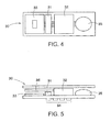
- Fig. 4 is a schematic plan view showing a structure of the time logger 30 in this embodiment
- Fig. 5 is a schematic side view thereof.
- the time logger 30 in this embodiment includes: a body unit 31 which is an IC chip with a timer; a battery 32 for electrically driving the body unit 31; an antenna 33 for transmitting and receiving a signal; an input terminal connection unit 34; and a start-up button 35 for starting up the battery.
- the time logger 30 in this embodiment further includes a protection substrate 36 for protecting the body unit 31 and the antenna 33, and for adjusting a play (thickness) for an operation of the start-up button 35. It is possible to employ a structure in which an insulation tape, in place of the start-up button 35, is disposed in the circuit and a user pulls it out therefrom.
- the tablet dispensing and managing container 10 in this embodiment is flat and not bulky, it is easy to carry the same. Then, tablets are dispensed one by one from the tablet dispensing and managing container 10 each and every predetermined and informed time at which a tablet should be dispensed, so that the tablets are taken one by one by the patient.
- the tablet dispensing and managing container 10 is held by the patient in such a manner that the outlet 13 of the lower case 12 is located below. At this time, one tablet reaches the dispensing standby space 15 by the tablet guide function of the tablet guide rail 24 and the pusher member 25, and a succeeding tablet follows the former tablet (see Fig. 3(a) ). In Figs. 3(a) to 3(c) , only the two tablets are illustrated for facilitating understanding. The tablet having reached the dispensing standby space 15 is stopped by the stopper projection 23 (see Fig. 3(a) ).
- the upper case 11 is slightly slid with respect to the lower case 12 (see Fig. 3(b) ).
- the tablet located in the dispensing standby space 15 is pushed by the stopper projection 23 in a direction away from the outlet 13.
- the pusher member 25 is provided in order to oppose the above pushing force. That is to say, the pusher member 25 pushes the tablet located in the dispensing standby space 15 toward the outlet 13 against the above pushing force.
- the tablet located in the dispensing standby space 15 is immobile for a while.
- the movable stopper part 23m of the stopper projection 23 is deflected for its deforming capability, and is going to get over a side surface of the tablet located in the dispensing standby space 15. Then, at an instance when the movable stopper part 23m of the stopper projection 23 is detached from an end surface on the side of the outlet 13 of the tablet located in the dispensing standby space 15, that is to say, at an instance when the tablet stopping function is released, the tablet runs off toward the outlet 13 by the pushing force given by the pusher member 25. On the other hand, the movable stopper part 23m of the stopper projection 23 stops an outlet-side surface of the tablet succeeding to the tablet having been located in the dispensing standby space 15. Fig. 3(c) shows this situation.
- the condition of the switch part 21s (conductive condition / electric connection condition) varies. Namely, in the condition of Fig. 3(a) , the switch part 21s is not retracted, and in the condition of Fig. 3(b) , the switch part 21s is subjected to the pushing force from the pushing part 23b so as to be retracted.
- the time logger 30 disposed on the electronic device plate 21 records a detection result about occurrence of dispensing of a tablet, along with time data.
- An electric operation of the time logger 30 is offered by power supplied from the battery 32.
- the battery 32 is preferably chargeable or replaceable.
- the user can properly dispense only one tablet merely by (1) holding the tablet dispensing and managing container 10 such that the outlet 13 is located below, and (2) sliding the upper case 11.
- the outlet 13 is formed on a side surface of the lower case 12, a tablet can be dispensed from the side surface of the tablet dispensing and managing container 10. This is very advantageous in terms of convenience for a user.
- the upper case 11 and the lower case 12 have a rectangular shape in plan view, the upper case 11 is slidably moved with respect to the lower case 12 in a longitudinal direction of the rectangular shape, and the outlet 13 is formed near to a corner of the rectangular shape.
- the tablet dispensing and managing container 10 has a general shape as a tablet dispensing container, which is convenient to a user.
- the lower case 12 is provided with the tablet guide rail 24 that bypasses the pusher member 25 so as to guide a tablet up to the dispensing standby space 15, a smooth guide operation of tablets inside the container body is promoted.
- an operation (labor) for adjusting movement of tablets by shaking the container body or the like can be saved.
- the pusher member 25 itself also has a function for guiding a tablet, the smooth guide operation of tablets inside the container body is further promoted.
- the lower case 12 since the lower case 12 has the rib 27 that is upstanding toward the upper case 11 and extends in the sliding direction, the upper case 11 can be effectively prevented from being excessively deflected and deformed. Thus, a duration of life of the container can be elongated.
- the accommodation recess 11r which is formed to be recessed from the upper case 11 toward the lower case 12, functions as a stopper against the tablet guide rail 24 of the lower case 12.
- a detection result about occurrence of dispensing of a tablet can be automatically recorded along with time data, without needing any operation or intension of a patient.
- a tablet is dispensed, i.e., when a tablet is taken by a patient can be automatically obtained.
- the hospital recovers the tablet dispensing and managing container 10 from the patient.
- the record of the time logger 30 is read out on a PC by a dedicated reader.
- the record of the time logger 30 can be effectively used for a subsequent dose instruction and a decision on an effective treatment method.
- Two types of usage of the tablet dispensing and managing container 10 can be considered.
- One is a case in which the tablet dispensing and managing container 10 is supplied as a medicinal product to a hospital, and the other is a case in which the tablet dispensing and managing container 10 is supplied as a refill container.
- the former is used only once, and the latter is repeatedly used within a battery life span by loading it with medicines in a hospital and handing it to a patient.
- the record of the time logger 30 is reset, and the start-up button 35 is pushed again so that the time logger 30 is turned off.
- the inside of the container body of the tablet dispensing and managing container 10 is cleaned. Thereafter, the tablet dispensing and managing container 10 can be repeatedly used for the same tablet prescription or another tablet prescription.
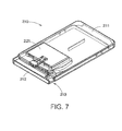
- Fig. 6 is a schematic perspective view showing a structure of the tablet dispensing and managing container in a second embodiment of the present invention
- Fig. 7 is a schematic perspective view showing an opened condition of the tablet dispensing and managing container of Fig. 6
- the tablet dispensing and managing container 210 in this embodiment also includes an upper case 211 and a lower case 212 which are configured to slide with each other.
- the upper case 211 and the lower case 212 form a container body capable of containing a plurality of tablets together.
- the container body is opened or closed.
- an outlet 213 for dispensing a tablet is exposed.
- the outlet 213 is sized to allow only one tablet to be dispensed therefrom at a time.
- the upper case 211 and the lower case 212 have a rectangular shape in plan view.
- the upper case 211 is slidably moved with respect to the lower case 212 in a longitudinal direction of the rectangular shape.
- the outlet 213 is formed near to a corner of the rectangular shape.
- a site in communication with the outlet 213 functions as a dispensing standby space 215.
- the lower case 212 has the dispensing standby space 215 in communication with the outlet 213.
- the upper case 211 is provided with a stopper projection 223 that projects to between the outlet 213 and the dispensing standby space 215, in a situation where the container body is closed.
- the stopper projection 223 in this embodiment includes a wire fixing part 232f fixed on the upper case 211, a flexibly deformable wire 223m extending from the wire fixing part 223f, and a slidably movable part 223s that is slidably movable in a direction where the slidably movable part 223s pushes the flexibly deformable wire 223m.
- One end side of the slidably movable part 223s projects to between the outlet 213 and the dispensing standby space 215, in a situation where the container body is closed.
- the slidably movable direction of the slidably movable part 223 is restricted by a guide rail 211g formed on the upper case 211 and a low wall part 224e provided on the lower case 212.
- the slidably movable part 223s is subjected to a force from a tablet located in the dispensing standby space 215, so that the slidably movable part 223s is slid while it flexibly deforms the flexibly deformable wire 223m.
- Figs. 8(a) to 8(c) are plan views showing how the stopper projection 223 of the tablet dispensing and managing container 210 of Figs. 6 and 7 gets over a side surface of a tablet.
- an accommodation recess 211r in which an electronic device plate 221 can be accommodated is formed on an upper surface side of the upper case 211.
- the accommodation recess 211r is composed of a bottom surface and four sidewalls surrounding a perimeter of the electronic device plate 221.
- the electronic device plate 221 is fitted in the accommodation recess 211r.
- the wire fixing part 223f of the stopper projection 223 is fixed on the upper case 211 adjacently to the corresponding sidewall of the accommodation recess 211r.
- Two conductive wires AW and BW extend from the wire fixing part 223f to the electronic device plate 221 through an opening window 211w formed in the bottom surface of the accommodation recess 211r.
- the conductive wire AW is electrically connected to the flexibly deformable wire 223m
- the conductive wire BW is electrically connected to a switch wire 221s.
- the switch wire 221s is brought into contact with the flexibly deformable wire 223 so as to be electrically connected thereto.
- the lower case 212 is provided with a pusher member 225 that is positioned on a side opposed to the stopper projection 223 with respect to the dispensing standby space 215, in a situation where the container body is closed.
- the pusher member 225 is configured to, during an operation of the upper case 211, push a tablet located in the dispensing standby space 215.
- the tablet located in the dispensing standby space 15 is firstly pushed in a direction away from the outlet 213 by the stopper projection 223.
- the pusher member 225 is provided in order to oppose the above (first) pushing force. That is to say, the pusher member 225 is configured to push the tablet located in the dispensing standby space 215 toward the outlet 213 against the above pushing force.
- the pusher member 225 in this embodiment is formed like a linear wall. One end of the pusher member 225 is fixed on a sidewall of the lower case 212, and the other end is configured to push a tablet.
- the lower case 212 has a tablet guide rail 224 that bypasses the pusher member 225 so as to guide a tablet up to the dispensing standby space 215.
- the tablet guide rail 224 in this embodiment bends on a side distant from the pusher member 225 (the side that does not need a function of bypassing the pusher member 225) and extends in a width direction of the case so as to function as a stopper against the accommodation recess 211r of the upper case 211.
- the tablet guide rail 224 in this embodiment is continuous to a low wall part 224e having a reduced height, and is further continuous to a tablet guide rail 212r having a substantially arcuate cross-section.
- the pusher member 225 itself has a function as a guide rail for guiding a tablet up to the dispensing standby space 215.
- the lower case 212 has a rib 227 that is upstanding toward the upper case 211 and extends in the sliding direction.
- the electronic device plate 221 further includes a circuit configured to detect (judge) dispensing (passage) of a tablet based on occurrence of electric connection between the flexibly deformable wire 223m and the switch wire 221s, and a data recording unit for recording the detection result. Also in this embodiment, similarly to the first embodiment, there is provided a time logger 30 configured to record a detection result about occurrence of dispensing of a tablet, along with time data.
- the tablet dispensing and managing container 210 is held by a patient in such a manner that the outlet 213 of the lower case 212 is located below.
- one tablet reaches the dispensing standby space 215 by the tablet guide function of the tablet guide rail 224 and the pusher member 225, and a succeeding tablet follows the former tablet (see Fig 8(a) ).
- Figs. 8(a) to 8(c) only the two tablets are illustrated for facilitating understanding.
- the tablet having reached the dispensing standby space 215 is stopped by the stopper projection 223 (see Fig. 8(a) ).
- the upper case 211 is slightly slid with respect to the lower case 212 (see Fig. 8(b) ).
- the tablet located in the dispensing standby space 215 is pushed by the slidably movable part 223s of the stopper projection 223 in a direction away from the outlet 213.
- the pusher member 225 is provided in order to oppose the above pushing force. That is to say, the pusher member 225 pushes the tablet located in the dispensing standby space 215 toward the outlet 213 against the above pushing force.
- the tablet in the dispensing standby space 215 is immobile for a while.
- the flexibly movable wire 223m in contact with the slidably movable part 223s of the stopper projection 223 is deflected for its deforming capability, so that the slidably movable part 223s is going to get over a side surface of the tablet located in the dispensing standby space 215. Then, at an instance when the slidably movable part 223s of the stopper projection 223 is detached from an end surface on the side of the outlet 223 of the tablet located in the dispensing standby space 215, that is to say, at an instance when the tablet stopping function is released, the tablet runs off toward the outlet 213 by the pushing force given by the pusher member 225.
- the conductive condition (electric connection condition) between the flexibly deformable wire 223m and the switch wire 221s varies. Namely, in the condition of Fig. 8(a) , the flexibly deformable wire 223m and the switch wire 221s are not electrically connected to each other, but in the condition of Fig. 8(b) , the flexibly deformable wire 223m and the switch wire 221s are electrically connected to each other.
- the time logger 30 disposed on the electronic device plate 221 records a detection result about occurrence of dispensing of a tablet, along with time data.
- An electric operation of the time logger 30 is offered by power supplied from the battery 32.
- the battery 32 is preferably chargeable or replaceable.
- the user can properly dispense only one tablet merely by (1) holding the tablet dispensing and managing container 210 such that the outlet 213 is located below, and (2) sliding the upper case 211.
- the outlet 213 is formed on a side surface of the lower case 212, a tablet can be dispensed from the side surface of the tablet dispensing and managing container 210. This is very advantageous in terms of convenience for a user.
- the upper case 211 and the lower case 212 have a rectangular shape in plan view.
- the upper case 211 is slidably moved with respect to the lower case 212 in a longitudinal direction of the rectangular shape.
- the outlet 213 is formed near to a corner of the rectangular shape.
- the tablet dispensing and managing container 210 has a general shape as a tablet dispensing container, which is convenient to a user.
- the lower case 212 is provided with the tablet guide rail 224 that bypasses the pusher member 225 so as to guide a tablet up to the dispensing standby space 215, a smooth guide operation of tablets inside the container body is promoted. Thus, an operation (labor) for adjusting movement of tablets by shaking the container body or the like can be saved.
- the pusher member 225 itself also has a function for guiding a tablet, the smooth guide operation of tablets inside the container body is further promoted.
- the lower case 212 since the lower case 212 has the rib 227 that is upstanding toward the upper case 211 and extends in the sliding direction, the upper case 211 can be effectively prevented from being excessively deflected and deformed. Thus, a duration of life of the container can be elongated.
- the accommodation recess 211r which is formed to be recessed from the upper case 211 toward the lower case 212, functions as a stopper against the tablet guide rail 224 of the lower case 212.
- a detection result about occurrence of dispensing of a tablet can be automatically recorded along with time data, without needing any operation or intension of a patient.
- a tablet is dispensed, i.e., when a tablet is taken by a patient can be automatically obtained.
- Fig. 9 is a schematic perspective view showing a structure of the tablet dispensing and managing container in a third embodiment of the present invention
- Fig. 10 is a longitudinal sectional view of the tablet dispensing and managing container of Fig. 9
- the tablet dispensing and managing container 310 in this embodiment is provided with, in place of the rib 27, a substantially annular rib 327 which differs from the rib 27 in arrangement and shape.
- a CR mechanism 330 is disposed near to the substantially annular rib 327.
- the other structure is substantially the same as the first embodiment described with reference to Figs. 1 to 5 .
- Figs. 9 and 10 a structure corresponding to a structure of the first embodiment is shown by the same reference number, and detailed description thereof is omitted.
- the CR mechanism 330 in this embodiment includes: a claw part 331 disposed on an upper case 11 to project toward a lower case 12; a claw receiving part 332 disposed on the lower case 12 so as to be engaged with the claw part 331; resilient parts 333a and 333b connected to the claw part 331, the resilient parts 333a and 333b being deformable to move the claw part 331 away from the claw receiving part 332 so that the claw part 331 and the claw receiving part 332 are disengaged from each other; and a pushing part 334 configured to deform the resilient parts 333a and 333b in the above manner.
- the pushing part 334 is located between the claw part 331 and the resilient parts 333a and 333b.
- the claw part 331 is supported on the upper case 11 through the pushing part 334 and the resilient parts 333a and 333b.
- the resilient parts 333a and 333b are deformed so that the claw part 331 and the claw receiving part 332 are disengaged from each other.
- the resilient parts 333a and 333b are returned to the original shapes so that the claw part 331 and the claw receiving part 332 can be again engaged with each other.
- a CR function given by the CR mechanism 330 can be obtained. Namely, in the normal condition where the resilient parts 333a and 333b are not deformed, the sufficient CR function can be provided. On the other hand, when the resilient parts 333a and 333b are deformed by the pushing action to the pushing part 334, the CR function can be easily released.
- the upper case 11 is provided with the claw part 331 and the lower case 12 is provided with the claw receiving part 332, the reverse configuration is possible.
- the lower case 12 may be provided with the claw part and the upper case 11 may be provided with the claw receiving part.
- the resilient parts 333a and 333b are connected to the claw part 331 and are deformable to move the claw part 331 away from the claw receiving part 332 so that the claw part 331 and the claw receiving part 332 are disengaged from each other.
- the resilient parts may be connected to the claw receiving part, and may be deformable to move the claw receiving part away from the claw part so that the claw receiving part and the claw part are disengaged from each other.
- the structure for deforming the resilient parts 333a and 333b is not limited to the pushing part 334.
- a "tab-like" projection to which an operator can exert a pulling-up force or a rotating force.
Landscapes
- Health & Medical Sciences (AREA)
- Life Sciences & Earth Sciences (AREA)
- Animal Behavior & Ethology (AREA)
- General Health & Medical Sciences (AREA)
- Public Health (AREA)
- Veterinary Medicine (AREA)
- Engineering & Computer Science (AREA)
- Medical Informatics (AREA)
- Mechanical Engineering (AREA)
- Pharmacology & Pharmacy (AREA)
- Medical Preparation Storing Or Oral Administration Devices (AREA)
Abstract
Description
- The present invention relates to a tablet container capable of containing a plurality of tablets together.
- Various tablets (the expression "tablets" includes capsules in this specification) are used as pharmaceutical products. Some tablets are commercially available in drug stores and other tablets are prescribed in hospitals or the like.
- Expected medicinal effect of tablets prescribed in hospitals or the like can be obtained by obeying a dosing instruction (also hours between doses depending on a medicine type). However, recent surveys in Europe and in the United States show that the dose compliance rate is generally low, although it depends on a medicine type. The average dose compliance rate is about 50% even in developed countries such as Europe and the United states, and is 30% level in developing countries. Although there is no science-based data for Japan, the dose compliance rate in Japan is estimated as 40 to 50%.
- In the medical site, to make a patient obey hours between doses is recognized as an emergent and important issue. However, there have been rarely effective measures therefor. There has been only a valid countermeasure, which is to improve a patient's consciousness by an informed consent.
- Recently, a new attempt has started to improve a patient's compliance by enhancing a function of "PTP (Press-Through Package) packaging : independent tablet package". An achievement thereof could be confirmed in Europe and the United States, and sales promotion thereof has started in Japan. A typical example is a PTP card packaging (named adherence packaging (adherence has almost the same meaning as compliance)) manufactured by MWV Co. (USA). Some hundred million cases thereof were already actually sold in the US market.
- In addition, there is a packaging (called "monitoring packaging") having a dose information recording function, which is formed by mounting an electronic device on the PTP packaging. Cypak Co. (Swed.), StraEnso Co. (Swed.), Confrerie Co. (Switz.) and so on actually develop such products. The monitoring packaging has a function for automatically recording a time when a medicine is dispensed. In addition, it is possible to provide the monitoring packaging with a function for informing a patient of a time when a medicine should be taken, a query function to a patient (effective in pain control) and so on.
-
JP2009-102064A - However, a packaging formed by improving the "PTP (Press-Through Package) Packaging", such as the adherence packaging by MWV Co., the monitoring packaging by Confrerie Co. and the like, is costly.
- The present invention has been made in view of the above circumstances. The object of the present invention is to provide a tablet container capable of containing a plurality of tablets together, which is a tablet dispensing and managing container that can be manufactured at a relatively low cost and is capable of automatically managing information about dispensing of the tablets.
- The present invention is a tablet dispensing and managing container including: an upper case and a lower case, the upper case and the lower case being configured to form a container body capable of containing a plurality of tablets together; a sensor unit configured to detect occurrence of dispensing of a tablet; a data recording unit configured to record a detection result by the sensor unit; and a battery for the data recording unit; wherein: when the upper case is slid with respect to the lower case, the container body is opened or closed; the lower case is provided with an outlet that is sized to allow only one tablet to be dispensed therefrom at a time, and with a dispensing standby space in communication with the outlet; the upper case is provided with a stopper projection that projects to between the outlet and the dispensing standby space, in a situation where the container body is closed; the lower case is provided with a pusher member that is positioned on a side opposed to the stopper projection with respect to the dispensing standby space, in a situation where the container body is closed, the pusher member being configured to, during an operation for opening the upper case, push a tablet located in the dispensing standby space toward the outlet; during the operation for opening the upper case, the stopper projection is configured to be deformed or displaced to get over a side surface of a tablet located in the dispensing standby space, and is configured to stop an outlet-side surface of a tablet succeeding to the tablet having been located in the dispensing standby space; and the sensor unit is configured to detect passage of one tablet moving from the dispensing standby space to the outlet so as to detect occurrence of dispensing of the tablet.
- According to the present invention, since the tablet dispensing and managing container includes the sensor unit configured to detect occurrence of dispensing of a tablet, and the data recording unit configured to record a detection result by the sensor unit, information about dispensing of a tablet can be automatically managed. In addition, since the tablet dispensing and managing container has the container body capable of containing a plurality of tablets together, the tablet dispensing and managing container can be manufactured at a relatively low cost. In addition, it is easy to use the tablet dispensing and managing container repeatedly.
- In addition, according to the present invention, during the operation for opening the upper case, the upper case or the stopper projection is configured to be flexibly deformed so that the stopper projection gets over a side surface of a tablet located in the dispensing standby space, and is configured to stop an outlet-side surface of a tablet succeeding to the tablet having been located in the dispensing standby space. Since the pusher member has been pushing the tablet located in the dispensing standby space toward the outlet, the tablet located in the dispensing standby space can be solely dispensed from the outlet by the pushing force.
- Due to this tablet dispensing principle, the number of tablets dispensed by one operation for opening the upper case can be more reliably adjusted to be "one" each and every time. Thus, the information about dispensing of a tablet can be reliably used as information about taking of the tablet.
- In addition, according to the tablet dispensing principle of the present invention, the outlet can be formed in a side surface of the case. Namely, a tablet can be dispensed from the side surface of the case, which is very advantageous in terms of convenience for a user.
- The stopper projection is disposed to extend downward from the upper case. Alternatively, the stopper projection may be formed to include: a flexibly deformable part extending from the upper case; and a slidably movable part that is slidably movable in a direction where the slidably movable part pushes the flexibly deformable part. In this case, the flexibly deformable part and the slidably movable part may be constituted as discrete separate members which can be joined to each other, or may be constituted as one member connected at ends thereof or the like.
- The sensor unit is configured to detect passage of a tablet by an electric connection between an electric conductor and an electric terminal, the electric conductor and the electric terminal being configured to be deformed or displaced by the passage of the tablet. In this case, the sensor unit can be packaged at a low cost and in a compact size. To be specific, it is possible to use a commercially available switch device which is not so expensive but has a high performance. In addition, since it is possible to employ a structure in which power is consumed only when the electric conductor and the electric terminal are electrically connected to each other, a power consumption of the battery can be restrained.
- Preferably, the data recording unit is a time logger configured to record a detection result by the sensor unit along with time data. In this case, time data about dispensing of a tablet can be automatically recorded.
- In addition, preferably, the upper case and the lower case have a rectangular shape in plan view; the upper case is slidably moved with respect to the lower case in a longitudinal direction of the rectangular shape; and the outlet is formed near to a corner of the rectangular shape. This configuration is general as a tablet dispensing container, which is advantageous in terms of convenience for a user. Further in this case, the lower case is preferably provided with a tablet guide rail that bypasses the pusher member so as to guide a tablet up to the dispensing standby space. When this structure is employed, since a smooth guide operation of tablets inside the container body is promoted, an operation (labor) for adjusting movement of tablets by shaking the container body or the like can be saved.
- In addition, preferably, the lower case is provided with a rib that is upstanding toward the upper case and extends in the sliding direction. Alternatively, preferably, the upper case is provided with a rib that extends down to the lower case and extends in the sliding direction. In these cases, the upper case can be effectively prevented from being excessively deflected and deformed. Thus, a duration of life of the container can be elongated. In place of the rib, a plurality of discontinuous bosses, which provide the same function as that of the rib, may be disposed.
- In addition, preferably, the upper case is provided with a CR mechanism configured to prevent that the upper case is slidably moved with respect to the lower case. The CR mechanism means a mechanism having a Child Resistance function (a function for preventing accidental ingestion by a child). In developed countries such as Europe and the United States, the use of such a mechanism is obliged by a legal stipulation.
- As a concrete example, the CR mechanism includes: a claw part disposed on one of the upper case and the lower case, the claw part projecting toward the other of the upper case and the lower case; a claw receiving part disposed on the other of the upper case and the lower case, the claw receiving part being engageable with the claw part; and a resilient part connected to one of the claw part and the claw receiving part, the resilient part being deformable to move one of the claw part and the claw receiving part away from the other of the claw part and the claw receiving part, so that the claw part and the claw receiving part are disengaged from each other. When such a structure is employed, in a normal situation where the resilient part is not deformed, a sufficient CR function can be provided. On the other hand, when the resilient part is deformed, the CR function can be easily released.
-
-
Fig. 1 is a schematic perspective view showing a structure of a tablet dispensing and managing container in a first embodiment of the present invention; -
Fig. 2 is a schematic perspective view showing an opened condition of the tablet dispensing and managing container ofFig. 1 ; -
Fig. 3 is a schematic view for explaining a relationship between a movement of tablets brought about by a tablet dispensing operation (operation for opening an upper case) of the tablet dispensing and managing container ofFig. 1 and a condition of a switch part; -
Fig. 4 is a schematic plan view showing a structure of a time logger of the tablet dispensing and managing container ofFig. 1 ; -
Fig. 5 is a schematic side view showing a structure of the time logger ofFig. 3 ; -
Fig. 6 is a schematic perspective view showing a structure of the tablet dispensing and managing container in a second embodiment of the present invention; -
Fig. 7 is a schematic perspective view showing an opened condition of the tablet dispensing and managing container ofFig. 5 ; -
Fig. 8 is a schematic view for explaining a relationship between a movement of tablets brought about by a tablet dispensing operation (operation for opening an upper case) of the tablet dispensing and managing container ofFig. 5 and a connection condition of an electric wire; -
Fig. 9 is a schematic perspective view showing a structure of the tablet dispensing and managing container in a third embodiment of the present invention; and -
Fig. 10 is a longitudinal sectional view of the tablet dispensing and managing container ofFig. 9 . - Embodiments of the present invention will be described in detail below with reference to the attached drawings.
-
Fig. 1 is a schematic perspective view showing a structure of a tablet dispensing and managing container in a first embodiment of the present invention, andFig. 2 is a schematic perspective view showing an opened condition of the tablet dispensing and managing container ofFig. 1 . As shown inFigs. 1 and2 , the tablet dispensing and managingcontainer 10 in this embodiment includes anupper case 11 and alower case 12 which are configured to slide with each other. Theupper case 11 and thelower case 12 form a container body capable of containing a plurality of tablets together. When theupper case 11 is slid with respect to thelower case 12, the container body is opened or closed. - To be specific, as shown in
Fig. 2 , when theupper case 11 is slightly slid with respect to thelower case 12, anoutlet 13 for dispensing a tablet is exposed. Theoutlet 13 is sized to allow only one tablet to be dispensed therefrom at a time. - As apparent from
Figs. 1 and2 , theupper case 11 and thelower case 12 in this embodiment have a rectangular shape in plan view. Theupper case 11 is configured to be slidably moved with respect to thelower case 12 in a longitudinal direction of the rectangular shape. Theoutlet 13 is formed near to a corner of the rectangular shape. - In this embodiment, a site in communication with the
outlet 13 functions as a dispensingstandby space 15. Namely, thelower case 12 has the dispensingstandby space 15 in communication with theoutlet 13. On the other hand, theupper case 11 is provided with astopper projection 23 which extends downward between theoutlet 13 and the dispensingstandby space 15, in a situation where the container body is closed. - The
stopper projection 23 in this embodiment has atubular part 23c extending downward from theupper case 11, and amovable stopper part 23m extending from thetubular part 23c up to between theoutlet 13 and the dispensingstandby space 15. Thetubular part 23c has an oblong (elongated circular) cross-section, and themovable stopper part 23m has a substantially arcuate cross-section. During an operation for opening theupper case 11, themovable stopper part 23m is flexibly deformed to get over a side surface of a tablet located in the dispensingstandby space 15, and then stops an outlet-side surface of a tablet succeeding to the tablet having been located in the dispensingstandby space 15. In other words, themovable stopper part 23m of thestopper projection 23 has such a deforming capability (resiliency).Figs. 3(a) to 3(c) are plan views showing how thestopper projection 23 of the tablet dispensing and managingcontainer 10 ofFigs. 1 and2 gets over a side surface of a tablet. - In addition, in this embodiment, an
accommodation recess 11r in which anelectronic device plate 21 can be accommodated is formed on an upper surface side of theupper case 11. Theaccommodation recess 11r is composed of a bottom surface and four sidewalls surrounding a perimeter of theelectronic device plate 21. Theelectronic device plate 21 is fitted in theaccommodation recess 11r. - The
electronic device plate 21 has, on a side surface thereof, an exposedswitch part 21s which is retracted when subjected to a pushing force. Theswitch part 21s passes through anopening window 11w formed in the corresponding sidewall of theaccommodation recess 11r of theupper case 11. - The
stopper projection 23 in this embodiment has a pushingpart 23p which imposes a pushing force to theswitch part 21s in conjunction with the flexible deformation of themovable stopper part 23m. On the other hand, in order to prevent, in a situation where the container body is closed, an erroneous operation caused by vibrations or the like of the pushingpart 23p, thestopper projection 23 in this embodiment is provided with adepression 23r. In a situation where the container body is closed, thedepression 23r is engaged with an end portion of atablet guide rail 12r having a substantially arcuate cross-section formed in the lower case 12 (seeFigs. 1 and3 ). - The
lower case 12 is provided with apusher member 25 that is positioned on a side opposed to thestopper projection 23 with respect to the dispensingstandby space 15, in a situation where the container body is closed. Thepusher member 25 is configured to, during an operation for opening theupper case 11, push a tablet located in the dispensingstandby space 15 toward theoutlet 13. In more detail, during the operation for opening theupper case 11, the tablet located in the dispensingstandby space 15 is firstly pushed in a direction away from theoutlet 13 by thestopper projection 23. Thepusher member 25 is provided in order to oppose the above (first) pushing force. That is to say, thepusher member 25 is configured to push the tablet located in the dispensingstandby space 15 toward theoutlet 13 against the above pushing force. - The
pusher member 25 in this embodiment is formed like a linear wall. One end of thepusher member 25 is fixed on a sidewall of thelower case 12, and the other end is configured to push a tablet. - In addition, in this embodiment, the
lower case 12 has atablet guide rail 24 that bypasses thepusher member 25 so as to guide a tablet up to the dispensingstandby space 15. Thetablet guide rail 24 in this embodiment bends on a side distant from the pusher member 25 (the side that does not need a function for bypassing the pusher member 25) and extends in a width direction of the case so as to function as a stopper against theaccommodation recess 11r of theupper case 11. In addition, in this embodiment, thepusher member 25 itself has a function as a guide rail for guiding a tablet to the dispensingstandby space 15. Moreover, thelower case 12 has arib 27 that is upstanding toward theupper case 11 and extends in the sliding direction. - The
electronic device plate 21 further includes a circuit configured to detect (judge) dispensing (passage) of a tablet based on occurrence of a retracting action (action when pushed) of theswitch part 21s, and a data recording unit for recording the detection result. In this embodiment, there is provided atime logger 30 configured to record a detection result about occurrence of dispensing of a tablet, along with time data.Fig. 4 is a schematic plan view showing a structure of thetime logger 30 in this embodiment, andFig. 5 is a schematic side view thereof. - As shown in
Figs. 4 and 5 , thetime logger 30 in this embodiment includes: abody unit 31 which is an IC chip with a timer; abattery 32 for electrically driving thebody unit 31; anantenna 33 for transmitting and receiving a signal; an inputterminal connection unit 34; and a start-upbutton 35 for starting up the battery. Thetime logger 30 in this embodiment further includes aprotection substrate 36 for protecting thebody unit 31 and theantenna 33, and for adjusting a play (thickness) for an operation of the start-upbutton 35. It is possible to employ a structure in which an insulation tape, in place of the start-upbutton 35, is disposed in the circuit and a user pulls it out therefrom. - Next, an operation of the tablet dispensing and managing
container 10 in this embodiment is described. - Firstly, immediately before the tablet dispensing and managing
container 10 is handed to a patient in a hospital or the like, how to use the tablet dispensing and managingcontainer 10 and functions of the tablet dispensing and managingcontainer 10 are explained to the patient. After the patient's understanding has been confirmed, the start-upbutton 35 is pushed or the insulation tape is pulled out, so that thetime logger 30 is turned on. The patient brings such a tablet dispensing and managingcontainer 10 to home. - As shown in
Figs. 1 and2 , since the tablet dispensing and managingcontainer 10 in this embodiment is flat and not bulky, it is easy to carry the same. Then, tablets are dispensed one by one from the tablet dispensing and managingcontainer 10 each and every predetermined and informed time at which a tablet should be dispensed, so that the tablets are taken one by one by the patient. - In order that the tablets are dispensed one by one from the tablet dispensing and managing
container 10, the tablet dispensing and managingcontainer 10 is held by the patient in such a manner that theoutlet 13 of thelower case 12 is located below. At this time, one tablet reaches the dispensingstandby space 15 by the tablet guide function of thetablet guide rail 24 and thepusher member 25, and a succeeding tablet follows the former tablet (seeFig. 3(a) ). InFigs. 3(a) to 3(c) , only the two tablets are illustrated for facilitating understanding. The tablet having reached thedispensing standby space 15 is stopped by the stopper projection 23 (seeFig. 3(a) ). - Then, an operation for opening the
upper case 11 is carried out. Namely, theupper case 11 is slightly slid with respect to the lower case 12 (seeFig. 3(b) ). At this time, the tablet located in the dispensingstandby space 15 is pushed by thestopper projection 23 in a direction away from theoutlet 13. However, thepusher member 25 is provided in order to oppose the above pushing force. That is to say, thepusher member 25 pushes the tablet located in the dispensingstandby space 15 toward theoutlet 13 against the above pushing force. Thus, the tablet located in the dispensingstandby space 15 is immobile for a while. - Instead, the
movable stopper part 23m of thestopper projection 23 is deflected for its deforming capability, and is going to get over a side surface of the tablet located in the dispensingstandby space 15. Then, at an instance when themovable stopper part 23m of thestopper projection 23 is detached from an end surface on the side of theoutlet 13 of the tablet located in the dispensingstandby space 15, that is to say, at an instance when the tablet stopping function is released, the tablet runs off toward theoutlet 13 by the pushing force given by thepusher member 25. On the other hand, themovable stopper part 23m of thestopper projection 23 stops an outlet-side surface of the tablet succeeding to the tablet having been located in the dispensingstandby space 15.Fig. 3(c) shows this situation. - Thereafter, the user returns the
upper case 11, which has been slid with respect to thelower case 12, to the original position. - During the above series of tablet dispensing operations, the condition of the
switch part 21s (conductive condition / electric connection condition) varies. Namely, in the condition ofFig. 3(a) , theswitch part 21s is not retracted, and in the condition ofFig. 3(b) , theswitch part 21s is subjected to the pushing force from the pushing part 23b so as to be retracted. - To be more specific, in the condition of
Fig. 3(b) , in conjunction with the resilient deformation of themovable stopper part 23m of thestopper projection 23, the pushingpart 23p of thestopper projection 23 is displaced in a direction where the pushingpart 23p pushes theswitch part 21s. Thus, theswitch part 21s is retracted. By detecting the retracting action (action when pushed), occurrence of dispensing (passage) of a tablet can be detected. - In this embodiment, the
time logger 30 disposed on theelectronic device plate 21 records a detection result about occurrence of dispensing of a tablet, along with time data. An electric operation of thetime logger 30 is offered by power supplied from thebattery 32. Thus, thebattery 32 is preferably chargeable or replaceable. - As described above, the user can properly dispense only one tablet merely by (1) holding the tablet dispensing and managing
container 10 such that theoutlet 13 is located below, and (2) sliding theupper case 11. - In particular, according to this embodiment, since the
outlet 13 is formed on a side surface of thelower case 12, a tablet can be dispensed from the side surface of the tablet dispensing and managingcontainer 10. This is very advantageous in terms of convenience for a user. - In addition, according to this embodiment, the
upper case 11 and thelower case 12 have a rectangular shape in plan view, theupper case 11 is slidably moved with respect to thelower case 12 in a longitudinal direction of the rectangular shape, and theoutlet 13 is formed near to a corner of the rectangular shape. Thus, the tablet dispensing and managingcontainer 10 has a general shape as a tablet dispensing container, which is convenient to a user. - Further, according to this embodiment, since the
lower case 12 is provided with thetablet guide rail 24 that bypasses thepusher member 25 so as to guide a tablet up to the dispensingstandby space 15, a smooth guide operation of tablets inside the container body is promoted. Thus, an operation (labor) for adjusting movement of tablets by shaking the container body or the like can be saved. - Moreover, according to this embodiment, since the
pusher member 25 itself also has a function for guiding a tablet, the smooth guide operation of tablets inside the container body is further promoted. - In addition, according to this embodiment, since the
lower case 12 has therib 27 that is upstanding toward theupper case 11 and extends in the sliding direction, theupper case 11 can be effectively prevented from being excessively deflected and deformed. Thus, a duration of life of the container can be elongated. - In addition, according to this embodiment, the
accommodation recess 11r, which is formed to be recessed from theupper case 11 toward thelower case 12, functions as a stopper against thetablet guide rail 24 of thelower case 12. Thus, it can be prevented that theupper case 11 is excessively slid with respect to thelower case 12 so that tablets therein are scattered. - In addition, during the above series of tablet dispensing operations, a detection result about occurrence of dispensing of a tablet can be automatically recorded along with time data, without needing any operation or intension of a patient. Thus, when a tablet is dispensed, i.e., when a tablet is taken by a patient can be automatically obtained.
- At the next time of visit of a patient, the hospital recovers the tablet dispensing and managing
container 10 from the patient. The record of thetime logger 30 is read out on a PC by a dedicated reader. Thus, the record of thetime logger 30 can be effectively used for a subsequent dose instruction and a decision on an effective treatment method. - Two types of usage of the tablet dispensing and managing
container 10 can be considered. One is a case in which the tablet dispensing and managingcontainer 10 is supplied as a medicinal product to a hospital, and the other is a case in which the tablet dispensing and managingcontainer 10 is supplied as a refill container. The former is used only once, and the latter is repeatedly used within a battery life span by loading it with medicines in a hospital and handing it to a patient. In the case of the latter refill container, the record of thetime logger 30 is reset, and the start-upbutton 35 is pushed again so that thetime logger 30 is turned off. Then, according to need, the inside of the container body of the tablet dispensing and managingcontainer 10 is cleaned. Thereafter, the tablet dispensing and managingcontainer 10 can be repeatedly used for the same tablet prescription or another tablet prescription. - Next,
Fig. 6 is a schematic perspective view showing a structure of the tablet dispensing and managing container in a second embodiment of the present invention, andFig. 7 is a schematic perspective view showing an opened condition of the tablet dispensing and managing container ofFig. 6 . As shown inFigs. 6 and7 , the tablet dispensing and managingcontainer 210 in this embodiment also includes anupper case 211 and alower case 212 which are configured to slide with each other. Theupper case 211 and thelower case 212 form a container body capable of containing a plurality of tablets together. When theupper case 211 is slid with respect to thelower case 212, the container body is opened or closed. - Also in this embodiment, similarly to the first embodiment, when the
upper case 211 is slightly slid with respect to thelower case 212, anoutlet 213 for dispensing a tablet is exposed. Theoutlet 213 is sized to allow only one tablet to be dispensed therefrom at a time. - Similarly to the first embodiment, the
upper case 211 and thelower case 212 have a rectangular shape in plan view. Theupper case 211 is slidably moved with respect to thelower case 212 in a longitudinal direction of the rectangular shape. Theoutlet 213 is formed near to a corner of the rectangular shape. - In addition, similarly to the first embodiment, a site in communication with the
outlet 213 functions as a dispensingstandby space 215. Namely, thelower case 212 has the dispensingstandby space 215 in communication with theoutlet 213. On the other hand, theupper case 211 is provided with astopper projection 223 that projects to between theoutlet 213 and the dispensingstandby space 215, in a situation where the container body is closed. - As shown in
Fig. 6 , thestopper projection 223 in this embodiment includes a wire fixing part 232f fixed on theupper case 211, a flexiblydeformable wire 223m extending from thewire fixing part 223f, and a slidablymovable part 223s that is slidably movable in a direction where the slidablymovable part 223s pushes the flexiblydeformable wire 223m. One end side of the slidablymovable part 223s projects to between theoutlet 213 and the dispensingstandby space 215, in a situation where the container body is closed. - The slidably movable direction of the slidably
movable part 223 is restricted by aguide rail 211g formed on theupper case 211 and alow wall part 224e provided on thelower case 212. During an operation for opening theupper case 211, the slidablymovable part 223s is subjected to a force from a tablet located in the dispensingstandby space 215, so that the slidablymovable part 223s is slid while it flexibly deforms the flexiblydeformable wire 223m. Thus, the slidablymovable part 223s gets over a side surface of the tablet located in the dispensingstandby space 215, and then stops an outlet-side surface of a tablet succeeding to the tablet having been located in the dispensingstandby space 215. In other words, the flexiblydeformable wire 223m of thestopper projection 223 has such a deforming capability (resiliency).Figs. 8(a) to 8(c) are plan views showing how thestopper projection 223 of the tablet dispensing and managingcontainer 210 ofFigs. 6 and7 gets over a side surface of a tablet. - In addition, in this embodiment, an
accommodation recess 211r in which anelectronic device plate 221 can be accommodated is formed on an upper surface side of theupper case 211. Theaccommodation recess 211r is composed of a bottom surface and four sidewalls surrounding a perimeter of theelectronic device plate 221. Theelectronic device plate 221 is fitted in theaccommodation recess 211r. - In addition, as shown in
Fig. 6 , thewire fixing part 223f of thestopper projection 223 is fixed on theupper case 211 adjacently to the corresponding sidewall of theaccommodation recess 211r. Two conductive wires AW and BW extend from thewire fixing part 223f to theelectronic device plate 221 through anopening window 211w formed in the bottom surface of theaccommodation recess 211r. The conductive wire AW is electrically connected to the flexiblydeformable wire 223m, and the conductive wire BW is electrically connected to aswitch wire 221s. When the flexiblydeformable wire 223m is flexibly deformed, theswitch wire 221s is brought into contact with the flexiblydeformable wire 223 so as to be electrically connected thereto. - The
lower case 212 is provided with apusher member 225 that is positioned on a side opposed to thestopper projection 223 with respect to the dispensingstandby space 215, in a situation where the container body is closed. Thepusher member 225 is configured to, during an operation of theupper case 211, push a tablet located in the dispensingstandby space 215. In more detail, during the operation for opening theupper case 211, the tablet located in the dispensingstandby space 15 is firstly pushed in a direction away from theoutlet 213 by thestopper projection 223. Thepusher member 225 is provided in order to oppose the above (first) pushing force. That is to say, thepusher member 225 is configured to push the tablet located in the dispensingstandby space 215 toward theoutlet 213 against the above pushing force. - The
pusher member 225 in this embodiment is formed like a linear wall. One end of thepusher member 225 is fixed on a sidewall of thelower case 212, and the other end is configured to push a tablet. - In addition, in this embodiment, the
lower case 212 has atablet guide rail 224 that bypasses thepusher member 225 so as to guide a tablet up to the dispensingstandby space 215. Thetablet guide rail 224 in this embodiment bends on a side distant from the pusher member 225 (the side that does not need a function of bypassing the pusher member 225) and extends in a width direction of the case so as to function as a stopper against theaccommodation recess 211r of theupper case 211. In addition, on the side of thepusher member 225, thetablet guide rail 224 in this embodiment is continuous to alow wall part 224e having a reduced height, and is further continuous to atablet guide rail 212r having a substantially arcuate cross-section. - In addition, in this embodiment, the
pusher member 225 itself has a function as a guide rail for guiding a tablet up to the dispensingstandby space 215. Moreover, thelower case 212 has arib 227 that is upstanding toward theupper case 211 and extends in the sliding direction. - The
electronic device plate 221 further includes a circuit configured to detect (judge) dispensing (passage) of a tablet based on occurrence of electric connection between the flexiblydeformable wire 223m and theswitch wire 221s, and a data recording unit for recording the detection result. Also in this embodiment, similarly to the first embodiment, there is provided atime logger 30 configured to record a detection result about occurrence of dispensing of a tablet, along with time data. - Next, an operation of the tablet dispensing and managing
container 210 in this embodiment is described. - Similarly to the first embodiment, in order that the tablets are dispensed one by one from the tablet dispensing and managing
container 210, the tablet dispensing and managingcontainer 210 is held by a patient in such a manner that theoutlet 213 of thelower case 212 is located below. At this time, one tablet reaches the dispensingstandby space 215 by the tablet guide function of thetablet guide rail 224 and thepusher member 225, and a succeeding tablet follows the former tablet (seeFig 8(a) ). InFigs. 8(a) to 8(c) , only the two tablets are illustrated for facilitating understanding. The tablet having reached thedispensing standby space 215 is stopped by the stopper projection 223 (seeFig. 8(a) ). - Then, an operation for opening the
upper case 211 is carried out. Namely, theupper case 211 is slightly slid with respect to the lower case 212 (seeFig. 8(b) ). At this time, the tablet located in the dispensingstandby space 215 is pushed by the slidablymovable part 223s of thestopper projection 223 in a direction away from theoutlet 213. However, thepusher member 225 is provided in order to oppose the above pushing force. That is to say, thepusher member 225 pushes the tablet located in the dispensingstandby space 215 toward theoutlet 213 against the above pushing force. Thus, the tablet in the dispensingstandby space 215 is immobile for a while. - Instead, the flexibly
movable wire 223m in contact with the slidablymovable part 223s of thestopper projection 223 is deflected for its deforming capability, so that the slidablymovable part 223s is going to get over a side surface of the tablet located in the dispensingstandby space 215. Then, at an instance when the slidablymovable part 223s of thestopper projection 223 is detached from an end surface on the side of theoutlet 223 of the tablet located in the dispensingstandby space 215, that is to say, at an instance when the tablet stopping function is released, the tablet runs off toward theoutlet 213 by the pushing force given by thepusher member 225. On the other hand, since the deformed flexiblydeformable wire 223m is returned to the original position, the slidablymovable part 223s of thestopper projection 223 stops an outlet-side surface of the tablet succeeding to the tablet having been located in the dispensingstandby space 215.Fig. 8(c) shows this situation. - Thereafter, the user returns the
upper case 211, which has been slid with respect to thelower case 212, to the original position. - During the above series of tablet dispensing operations, the conductive condition (electric connection condition) between the flexibly
deformable wire 223m and theswitch wire 221s varies. Namely, in the condition ofFig. 8(a) , the flexiblydeformable wire 223m and theswitch wire 221s are not electrically connected to each other, but in the condition ofFig. 8(b) , the flexiblydeformable wire 223m and theswitch wire 221s are electrically connected to each other. - Also in this embodiment, the
time logger 30 disposed on theelectronic device plate 221 records a detection result about occurrence of dispensing of a tablet, along with time data. An electric operation of thetime logger 30 is offered by power supplied from thebattery 32. Thus, thebattery 32 is preferably chargeable or replaceable. - As described above, also according to this embodiment, substantially the same effect as that of the first embodiment can be obtained. Namely, the user can properly dispense only one tablet merely by (1) holding the tablet dispensing and managing
container 210 such that theoutlet 213 is located below, and (2) sliding theupper case 211. In particular, also according to this embodiment, since theoutlet 213 is formed on a side surface of thelower case 212, a tablet can be dispensed from the side surface of the tablet dispensing and managingcontainer 210. This is very advantageous in terms of convenience for a user. - In addition, also according to this embodiment, the
upper case 211 and thelower case 212 have a rectangular shape in plan view. Theupper case 211 is slidably moved with respect to thelower case 212 in a longitudinal direction of the rectangular shape. Theoutlet 213 is formed near to a corner of the rectangular shape. Thus, the tablet dispensing and managingcontainer 210 has a general shape as a tablet dispensing container, which is convenient to a user. - Further, also according to this embodiment, since the
lower case 212 is provided with thetablet guide rail 224 that bypasses thepusher member 225 so as to guide a tablet up to the dispensingstandby space 215, a smooth guide operation of tablets inside the container body is promoted. Thus, an operation (labor) for adjusting movement of tablets by shaking the container body or the like can be saved. - Moreover, also according to this embodiment, since the
pusher member 225 itself also has a function for guiding a tablet, the smooth guide operation of tablets inside the container body is further promoted. - In addition, also according to this embodiment, since the
lower case 212 has therib 227 that is upstanding toward theupper case 211 and extends in the sliding direction, theupper case 211 can be effectively prevented from being excessively deflected and deformed. Thus, a duration of life of the container can be elongated. - In addition, also according to this embodiment, the
accommodation recess 211r, which is formed to be recessed from theupper case 211 toward thelower case 212, functions as a stopper against thetablet guide rail 224 of thelower case 212. Thus, it can be prevented that theupper case 211 is excessively slid with respect to thelower case 212 so that tablets therein are scattered. - In addition, during the above series of tablet dispensing operations, a detection result about occurrence of dispensing of a tablet can be automatically recorded along with time data, without needing any operation or intension of a patient. Thus, when a tablet is dispensed, i.e., when a tablet is taken by a patient can be automatically obtained.
- Next,
Fig. 9 is a schematic perspective view showing a structure of the tablet dispensing and managing container in a third embodiment of the present invention, andFig. 10 is a longitudinal sectional view of the tablet dispensing and managing container ofFig. 9 . As shown inFigs. 9 and10 , the tablet dispensing and managingcontainer 310 in this embodiment is provided with, in place of therib 27, a substantiallyannular rib 327 which differs from therib 27 in arrangement and shape. In addition, aCR mechanism 330 is disposed near to the substantiallyannular rib 327. - In this embodiment, the other structure is substantially the same as the first embodiment described with reference to
Figs. 1 to 5 . InFigs. 9 and10 , a structure corresponding to a structure of the first embodiment is shown by the same reference number, and detailed description thereof is omitted. - The
CR mechanism 330 in this embodiment includes: aclaw part 331 disposed on anupper case 11 to project toward alower case 12; aclaw receiving part 332 disposed on thelower case 12 so as to be engaged with theclaw part 331;resilient parts claw part 331, theresilient parts claw part 331 away from theclaw receiving part 332 so that theclaw part 331 and theclaw receiving part 332 are disengaged from each other; and a pushingpart 334 configured to deform theresilient parts part 334 is located between theclaw part 331 and theresilient parts claw part 331 is supported on theupper case 11 through the pushingpart 334 and theresilient parts - When the pushing
part 334 is pushed toward thelower case 12, theresilient parts claw part 331 and theclaw receiving part 332 are disengaged from each other. On the other hand, when the pushing force to the pushingpart 334 is removed, theresilient parts claw part 331 and theclaw receiving part 332 can be again engaged with each other. - According to this embodiment, in addition to the effect obtained by the first embodiment, a CR function given by the
CR mechanism 330 can be obtained. Namely, in the normal condition where theresilient parts resilient parts part 334, the CR function can be easily released. - Although, in this embodiment, the
upper case 11 is provided with theclaw part 331 and thelower case 12 is provided with theclaw receiving part 332, the reverse configuration is possible. Namely, thelower case 12 may be provided with the claw part and theupper case 11 may be provided with the claw receiving part. In addition, in this embodiment, theresilient parts claw part 331 and are deformable to move theclaw part 331 away from theclaw receiving part 332 so that theclaw part 331 and theclaw receiving part 332 are disengaged from each other. However, instead thereof, the resilient parts may be connected to the claw receiving part, and may be deformable to move the claw receiving part away from the claw part so that the claw receiving part and the claw part are disengaged from each other. - Further, the structure for deforming the
resilient parts part 334. For example, there may be used a "tab-like" projection to which an operator can exert a pulling-up force or a rotating force. -
- 10
- Tablet dispensing container
- 11
- Uppercase
- 11r
- Accommodation recess
- 11w
- Opening window
- 12
- Lower case
- 12r
- Tablet guide rail
- 13
- Outlet
- 15
- Dispensing standby space
- 21
- Electronic device plate
- 23
- Stopper projection
- 23c
- Tubular part
- 23m
- Movable stopper part
- 23p
- Pushing part
- 23r
- Depression
- 24
- Tablet guide rail
- 25
- Pusher member
- 27
- Rib
- 210
- Tablet dispensing container
- 211
- Upper case
- 211g
- Guide rail
- 211r
- Accommodation recess
- 211w
- Opening window
- 212
- Lower case
- 212r
- Tablet guide rail
- 213
- Outlet
- 215
- Dispensing standby space
- 221
- Electronic device plate
- 221s
- Switch wire
- 223
- Stopper projection
- 223f
- Wire fixing part
- 223s
- Slidably movable part
- 223m
- Flexibly deformable wire
- 224
- Tablet guide rail
- 224e
- Low wall part
- 225
- Pusher member
- 227
- Rib
- 310
- Tablet dispensing container
- 327
- Rib
- 330
- CR mechanism
- 331
- Claw part
- 332
- Claw receiving part
- 333a, 333b
- Resilient part
- 334
- Pushing part
Claims (9)
- A tablet dispensing and managing container comprising:an upper case and a lower case, the upper case and the lower case being configured to form a container body capable of containing a plurality of tablets together;a sensor unit configured to detect occurrence of dispensing of a tablet;a data recording unit configured to record a detection result by the sensor unit; anda battery for the data recording unit;wherein:when the upper case is slid with respect to the lower case, the container body is opened or closed;the lower case is provided with an outlet that is sized to allow only one tablet to be dispensed therefrom at a time, and with a dispensing standby space in communication with the outlet;the upper case is provided with a stopper projection that projects to between the outlet and the dispensing standby space, in a situation where the container body is closed;the lower case is provided with a pusher member that is positioned on a side opposed to the stopper projection with respect to the dispensing standby space, in a situation where the container body is closed, the pusher member being configured to, during an operation for opening the upper case, push a tablet located in the dispensing standby space toward the outlet;during the operation for opening the upper case, the stopper projection is configured to be deformed or displaced to get over a side surface of a tablet located in the dispensing standby space, and is configured to stop an outlet-side surface of a tablet succeeding to the tablet having been located in the dispensing standby space; andthe sensor unit is configured to detect passage of one tablet moving from the dispensing standby space to the outlet so as to detect occurrence of dispensing of the tablet.
- The tablet dispensing and managing container according to claim 1, wherein
the stopper projection is disposed to extend downward from the upper case. - The tablet dispensing and managing container according to claim 1, wherein
the stopper projection includes:a flexibly deformable part extending from the upper case; anda slidably movable part that is slidably movable in a direction where the slidably movable part pushes the flexibly deformable part. - The tablet dispensing and managing container according to any one of claims 1 to 3, wherein
the sensor unit is configured to detect passage of a tablet by an electric connection between an electric conductor and an electric terminal, the electric conductor and the electric terminal being configured to be deformed or displaced by the passage of the tablet. - The tablet dispensing and managing container according to any one of claims 1 to 4, wherein
the data recording unit is a time logger configured to record a detection result by the sensor unit along with time data. - The tablet dispensing and managing container according to any one of claims 1 to 5, wherein:the upper case and the lower case have a rectangular shape in plan view;the upper case is slidably moved with respect to the lower case in a longitudinal direction of the rectangular shape; andthe outlet is formed near to a corner of the rectangular shape.
- The tablet dispensing and managing container according to claim 6, wherein
the lower case is provided with a tablet guide rail that bypasses the pusher member so as to guide a tablet up to the dispensing standby space. - The tablet dispensing and managing container according to any one of claims 1 to 7, wherein
the upper case is provided with a CRSF mechanism configured to prevent that the upper case is slidably moved with respect to the lower case. - The tablet dispensing and managing container according to claim 8, wherein
the CRSF mechanism includes:a claw part disposed on one of the upper case and the lower case, the claw part projecting toward the other of the upper case and the lower case;a claw receiving part disposed on the other of the upper case and the lower case, the claw receiving part being engageable with the claw part; anda resilient part connected to one of the claw part and the claw receiving part, the resilient part being deformable to move one of the claw part and the claw receiving part away from the other of the claw part and the claw receiving part, so that the claw part and the claw receiving part are disengaged from each other.
Applications Claiming Priority (2)
| Application Number | Priority Date | Filing Date | Title |
|---|---|---|---|
| JP2012116790 | 2012-05-22 | ||
| PCT/JP2013/064290 WO2013176196A1 (en) | 2012-05-22 | 2013-05-22 | Controlled pill dispensing container |
Publications (3)
| Publication Number | Publication Date |
|---|---|
| EP2853505A1 true EP2853505A1 (en) | 2015-04-01 |
| EP2853505A4 EP2853505A4 (en) | 2016-01-06 |
| EP2853505B1 EP2853505B1 (en) | 2017-05-03 |
Family
ID=49623878
Family Applications (1)
| Application Number | Title | Priority Date | Filing Date |
|---|---|---|---|
| EP13793387.5A Not-in-force EP2853505B1 (en) | 2012-05-22 | 2013-05-22 | Controlled pill dispensing container |
Country Status (7)
| Country | Link |
|---|---|
| US (1) | US20150136800A1 (en) |
| EP (1) | EP2853505B1 (en) |
| JP (1) | JP6162111B2 (en) |
| KR (1) | KR20150021949A (en) |
| CN (1) | CN104520208B (en) |
| ES (1) | ES2625136T3 (en) |
| WO (1) | WO2013176196A1 (en) |
Cited By (2)
| Publication number | Priority date | Publication date | Assignee | Title |
|---|---|---|---|---|
| ITUB20155753A1 (en) * | 2015-11-19 | 2017-05-19 | Origicare S R L | Support device for blisters with expulsion detector circuit |
| WO2017216182A1 (en) * | 2016-06-14 | 2017-12-21 | Pilloxa Ab | Tablet container |
Families Citing this family (6)
| Publication number | Priority date | Publication date | Assignee | Title |
|---|---|---|---|---|
| AR098712A1 (en) * | 2013-12-13 | 2016-06-08 | Glaxosmithkline Llc | CONTAINER TO DISPOSE DOSE MEASURES |
| JP6323889B2 (en) * | 2014-09-17 | 2018-05-16 | 日本電気株式会社 | Tablet case |
| WO2018164099A1 (en) * | 2017-03-10 | 2018-09-13 | 日本電気株式会社 | Tablet extraction device, tablet extraction control method, and program storage medium |
| EP3542774A1 (en) * | 2018-03-21 | 2019-09-25 | Koninklijke Philips N.V. | Monitoring device for monitoring the delivery and taking of medication pills and a monitoring method |
| JP6738846B2 (en) * | 2018-03-13 | 2020-08-12 | 株式会社カナエ | container |
| US12070059B2 (en) | 2020-09-04 | 2024-08-27 | Nicoventures Trading Limited | Child-resistant container for tobacco-containing products |
Family Cites Families (11)
| Publication number | Priority date | Publication date | Assignee | Title |
|---|---|---|---|---|
| FR2788040B1 (en) * | 1998-12-31 | 2001-03-23 | Airsec Sa | DISTRIBUTOR OF OBJECTS |
| CN2386003Y (en) * | 1999-09-29 | 2000-07-05 | 杭州胡庆余堂药业有限公司 | Medicine box with quantitative tablet feeding device |
| JP2003221067A (en) * | 2002-01-25 | 2003-08-05 | Toppan Printing Co Ltd | Sheet storage case for press-through pack packaging |
| JP4522080B2 (en) * | 2002-11-25 | 2010-08-11 | 株式会社 服薬コンプライアンス研究所 | PTP sheet storage case, medication recorder, and medication recording system |
| GB0316348D0 (en) * | 2003-07-11 | 2003-08-13 | Glaxo Group Ltd | A dispenser |
| US7581642B2 (en) * | 2006-01-09 | 2009-09-01 | Anderson Packaging, Inc. | Child-resistant, senior-friendly unit dose container |
| DE202007013517U1 (en) * | 2007-09-27 | 2007-12-20 | Pöppelmann Holding GmbH & Co. KG | Dispenser or the like output tray |
| JP4247293B1 (en) | 2007-10-02 | 2009-04-02 | キタノ製作株式会社 | Weighing container |
| CN101214868A (en) * | 2007-12-29 | 2008-07-09 | 黄正武 | Container for granule |
| US7617935B2 (en) * | 2008-01-10 | 2009-11-17 | Anderson Packaging, Inc. | Reusable child-resistant, senior friendly unit dose container |
| JP2010143610A (en) * | 2008-12-18 | 2010-07-01 | Nanshin Kagaku Kogyo Kk | Tablet case |
-
2013
- 2013-05-22 US US14/402,750 patent/US20150136800A1/en not_active Abandoned
- 2013-05-22 WO PCT/JP2013/064290 patent/WO2013176196A1/en not_active Ceased
- 2013-05-22 JP JP2014516838A patent/JP6162111B2/en not_active Expired - Fee Related
- 2013-05-22 ES ES13793387.5T patent/ES2625136T3/en active Active
- 2013-05-22 EP EP13793387.5A patent/EP2853505B1/en not_active Not-in-force
- 2013-05-22 KR KR1020147035896A patent/KR20150021949A/en not_active Ceased
- 2013-05-22 CN CN201380026692.0A patent/CN104520208B/en not_active Expired - Fee Related
Cited By (3)
| Publication number | Priority date | Publication date | Assignee | Title |
|---|---|---|---|---|
| ITUB20155753A1 (en) * | 2015-11-19 | 2017-05-19 | Origicare S R L | Support device for blisters with expulsion detector circuit |
| WO2017085652A1 (en) * | 2015-11-19 | 2017-05-26 | Origicare Srl | Blister supporting device with an ejection detection circuit |
| WO2017216182A1 (en) * | 2016-06-14 | 2017-12-21 | Pilloxa Ab | Tablet container |
Also Published As
| Publication number | Publication date |
|---|---|
| EP2853505A4 (en) | 2016-01-06 |
| KR20150021949A (en) | 2015-03-03 |
| ES2625136T3 (en) | 2017-07-18 |
| EP2853505B1 (en) | 2017-05-03 |
| WO2013176196A1 (en) | 2013-11-28 |
| CN104520208B (en) | 2016-11-16 |
| US20150136800A1 (en) | 2015-05-21 |
| CN104520208A (en) | 2015-04-15 |
| JP6162111B2 (en) | 2017-07-12 |
| JPWO2013176196A1 (en) | 2016-01-14 |
Similar Documents
| Publication | Publication Date | Title |
|---|---|---|
| EP2853505B1 (en) | Controlled pill dispensing container | |
| RU2205144C2 (en) | Device for dispensing pills from transparent drawout package | |
| US6792736B1 (en) | Solid drug filling device | |
| EP1480897B1 (en) | Blister pack device | |
| EP2579830B2 (en) | Tablet dispenser | |
| EP2906176B1 (en) | Electronic monitoring device for use with blister packs | |
| JP7657811B2 (en) | SYSTEM AND METHOD FOR LOCKING A CONTROLLED MEDICAL TREATMENT DEVICE - Patent application | |
| CN101384237B (en) | A container for a blister package | |
| CA2820260C (en) | Medication cassette and dispensing tracking apparatus | |
| KR102379921B1 (en) | Portable Pill Dispenser Device Using Pill Cartridges with Enclosed Pill Strips | |
| CN110996880A (en) | tablet dispenser | |
| US20180243171A1 (en) | Packages with monitoring devices | |
| JPH0646998B2 (en) | Pill container | |
| US20030102324A1 (en) | Apparatus for dosage of medicaments | |
| KR20140089566A (en) | Tube for storing unit doses of a drug, method and device for filling same and dispensing cabinet using same | |
| CN112716788A (en) | Push type medicine box | |
| JP7701472B2 (en) | SYSTEM AND METHOD FOR DETECTING USE OF A CONTROLLED MEDICAL TREATMENT DEVICE - Patent application | |
| CN104603621B (en) | Interchangeable multi-bar cartridge and biosensor meter | |
| HK40018971A (en) | Tablet dispenser | |
| HK40109229A (en) | System and method for sensing usage of a controlled medical therapy device | |
| JP2019156413A (en) | container | |
| HK1126955B (en) | A container for a blister package |
Legal Events
| Date | Code | Title | Description |
|---|---|---|---|
| PUAI | Public reference made under article 153(3) epc to a published international application that has entered the european phase |
Free format text: ORIGINAL CODE: 0009012 |
|
| 17P | Request for examination filed |
Effective date: 20141121 |
|
| AK | Designated contracting states |
Kind code of ref document: A1 Designated state(s): AL AT BE BG CH CY CZ DE DK EE ES FI FR GB GR HR HU IE IS IT LI LT LU LV MC MK MT NL NO PL PT RO RS SE SI SK SM TR |
|
| AX | Request for extension of the european patent |
Extension state: BA ME |
|
| DAX | Request for extension of the european patent (deleted) | ||
| RA4 | Supplementary search report drawn up and despatched (corrected) |
Effective date: 20151204 |
|
| RIC1 | Information provided on ipc code assigned before grant |
Ipc: B65D 83/04 20060101AFI20151130BHEP Ipc: A61J 1/03 20060101ALI20151130BHEP Ipc: A61J 7/04 20060101ALI20151130BHEP Ipc: A61J 7/02 20060101ALI20151130BHEP |
|
| RIN1 | Information on inventor provided before grant (corrected) |
Inventor name: DODO, MASAAKI Inventor name: MIWATA, TORU Inventor name: IKEMOTO, KENJI Inventor name: KUBOTA, KIYOSHI |
|
| RAP1 | Party data changed (applicant data changed or rights of an application transferred) |
Owner name: IWATA LABEL CO., LTD. Owner name: CHUO SHOKO CO., LTD. Owner name: KITANO CO., LTD. Owner name: DAIICHI SANKYO COMPANY, LIMITED |
|
| RIC1 | Information provided on ipc code assigned before grant |
Ipc: A61J 7/02 20060101ALI20160923BHEP Ipc: A61J 7/04 20060101ALI20160923BHEP Ipc: A61J 1/03 20060101ALI20160923BHEP Ipc: B65D 83/04 20060101AFI20160923BHEP Ipc: A61J 7/00 20060101ALI20160923BHEP |
|
| RAP1 | Party data changed (applicant data changed or rights of an application transferred) |
Owner name: DAIICHI SANKYO COMPANY, LIMITED |
|
| GRAP | Despatch of communication of intention to grant a patent |
Free format text: ORIGINAL CODE: EPIDOSNIGR1 |
|
| INTG | Intention to grant announced |
Effective date: 20161124 |
|
| GRAS | Grant fee paid |
Free format text: ORIGINAL CODE: EPIDOSNIGR3 |
|
| GRAA | (expected) grant |
Free format text: ORIGINAL CODE: 0009210 |
|
| REG | Reference to a national code |
Ref country code: FR Ref legal event code: PLFP Year of fee payment: 5 |
|
| AK | Designated contracting states |
Kind code of ref document: B1 Designated state(s): AL AT BE BG CH CY CZ DE DK EE ES FI FR GB GR HR HU IE IS IT LI LT LU LV MC MK MT NL NO PL PT RO RS SE SI SK SM TR |
|
| REG | Reference to a national code |
Ref country code: GB Ref legal event code: FG4D |
|
| REG | Reference to a national code |
Ref country code: AT Ref legal event code: REF Ref document number: 889704 Country of ref document: AT Kind code of ref document: T Effective date: 20170515 Ref country code: CH Ref legal event code: EP |
|
| REG | Reference to a national code |
Ref country code: IE Ref legal event code: FG4D |
|
| REG | Reference to a national code |
Ref country code: DE Ref legal event code: R096 Ref document number: 602013020721 Country of ref document: DE |
|
| REG | Reference to a national code |
Ref country code: ES Ref legal event code: FG2A Ref document number: 2625136 Country of ref document: ES Kind code of ref document: T3 Effective date: 20170718 |
|
| REG | Reference to a national code |
Ref country code: NL Ref legal event code: MP Effective date: 20170503 |
|
| REG | Reference to a national code |
Ref country code: AT Ref legal event code: MK05 Ref document number: 889704 Country of ref document: AT Kind code of ref document: T Effective date: 20170503 |
|
| REG | Reference to a national code |
Ref country code: LT Ref legal event code: MG4D |
|
| PG25 | Lapsed in a contracting state [announced via postgrant information from national office to epo] |
Ref country code: GR Free format text: LAPSE BECAUSE OF FAILURE TO SUBMIT A TRANSLATION OF THE DESCRIPTION OR TO PAY THE FEE WITHIN THE PRESCRIBED TIME-LIMIT Effective date: 20170804 Ref country code: NO Free format text: LAPSE BECAUSE OF FAILURE TO SUBMIT A TRANSLATION OF THE DESCRIPTION OR TO PAY THE FEE WITHIN THE PRESCRIBED TIME-LIMIT Effective date: 20170803 Ref country code: LT Free format text: LAPSE BECAUSE OF FAILURE TO SUBMIT A TRANSLATION OF THE DESCRIPTION OR TO PAY THE FEE WITHIN THE PRESCRIBED TIME-LIMIT Effective date: 20170503 Ref country code: HR Free format text: LAPSE BECAUSE OF FAILURE TO SUBMIT A TRANSLATION OF THE DESCRIPTION OR TO PAY THE FEE WITHIN THE PRESCRIBED TIME-LIMIT Effective date: 20170503 Ref country code: FI Free format text: LAPSE BECAUSE OF FAILURE TO SUBMIT A TRANSLATION OF THE DESCRIPTION OR TO PAY THE FEE WITHIN THE PRESCRIBED TIME-LIMIT Effective date: 20170503 Ref country code: AT Free format text: LAPSE BECAUSE OF FAILURE TO SUBMIT A TRANSLATION OF THE DESCRIPTION OR TO PAY THE FEE WITHIN THE PRESCRIBED TIME-LIMIT Effective date: 20170503 |
|
| PG25 | Lapsed in a contracting state [announced via postgrant information from national office to epo] |
Ref country code: RS Free format text: LAPSE BECAUSE OF FAILURE TO SUBMIT A TRANSLATION OF THE DESCRIPTION OR TO PAY THE FEE WITHIN THE PRESCRIBED TIME-LIMIT Effective date: 20170503 Ref country code: PL Free format text: LAPSE BECAUSE OF FAILURE TO SUBMIT A TRANSLATION OF THE DESCRIPTION OR TO PAY THE FEE WITHIN THE PRESCRIBED TIME-LIMIT Effective date: 20170503 Ref country code: NL Free format text: LAPSE BECAUSE OF FAILURE TO SUBMIT A TRANSLATION OF THE DESCRIPTION OR TO PAY THE FEE WITHIN THE PRESCRIBED TIME-LIMIT Effective date: 20170503 Ref country code: IS Free format text: LAPSE BECAUSE OF FAILURE TO SUBMIT A TRANSLATION OF THE DESCRIPTION OR TO PAY THE FEE WITHIN THE PRESCRIBED TIME-LIMIT Effective date: 20170903 Ref country code: SE Free format text: LAPSE BECAUSE OF FAILURE TO SUBMIT A TRANSLATION OF THE DESCRIPTION OR TO PAY THE FEE WITHIN THE PRESCRIBED TIME-LIMIT Effective date: 20170503 Ref country code: LV Free format text: LAPSE BECAUSE OF FAILURE TO SUBMIT A TRANSLATION OF THE DESCRIPTION OR TO PAY THE FEE WITHIN THE PRESCRIBED TIME-LIMIT Effective date: 20170503 Ref country code: BG Free format text: LAPSE BECAUSE OF FAILURE TO SUBMIT A TRANSLATION OF THE DESCRIPTION OR TO PAY THE FEE WITHIN THE PRESCRIBED TIME-LIMIT Effective date: 20170803 |
|
| REG | Reference to a national code |
Ref country code: CH Ref legal event code: PL |
|
| PG25 | Lapsed in a contracting state [announced via postgrant information from national office to epo] |
Ref country code: RO Free format text: LAPSE BECAUSE OF FAILURE TO SUBMIT A TRANSLATION OF THE DESCRIPTION OR TO PAY THE FEE WITHIN THE PRESCRIBED TIME-LIMIT Effective date: 20170503 Ref country code: EE Free format text: LAPSE BECAUSE OF FAILURE TO SUBMIT A TRANSLATION OF THE DESCRIPTION OR TO PAY THE FEE WITHIN THE PRESCRIBED TIME-LIMIT Effective date: 20170503 Ref country code: CZ Free format text: LAPSE BECAUSE OF FAILURE TO SUBMIT A TRANSLATION OF THE DESCRIPTION OR TO PAY THE FEE WITHIN THE PRESCRIBED TIME-LIMIT Effective date: 20170503 Ref country code: DK Free format text: LAPSE BECAUSE OF FAILURE TO SUBMIT A TRANSLATION OF THE DESCRIPTION OR TO PAY THE FEE WITHIN THE PRESCRIBED TIME-LIMIT Effective date: 20170503 Ref country code: SK Free format text: LAPSE BECAUSE OF FAILURE TO SUBMIT A TRANSLATION OF THE DESCRIPTION OR TO PAY THE FEE WITHIN THE PRESCRIBED TIME-LIMIT Effective date: 20170503 |
|
| REG | Reference to a national code |
Ref country code: DE Ref legal event code: R097 Ref document number: 602013020721 Country of ref document: DE |
|
| REG | Reference to a national code |
Ref country code: IE Ref legal event code: MM4A |
|
| PG25 | Lapsed in a contracting state [announced via postgrant information from national office to epo] |
Ref country code: LI Free format text: LAPSE BECAUSE OF NON-PAYMENT OF DUE FEES Effective date: 20170531 Ref country code: SM Free format text: LAPSE BECAUSE OF FAILURE TO SUBMIT A TRANSLATION OF THE DESCRIPTION OR TO PAY THE FEE WITHIN THE PRESCRIBED TIME-LIMIT Effective date: 20170503 Ref country code: CH Free format text: LAPSE BECAUSE OF NON-PAYMENT OF DUE FEES Effective date: 20170531 |
|
| PLBE | No opposition filed within time limit |
Free format text: ORIGINAL CODE: 0009261 |
|
| STAA | Information on the status of an ep patent application or granted ep patent |
Free format text: STATUS: NO OPPOSITION FILED WITHIN TIME LIMIT |
|
| PG25 | Lapsed in a contracting state [announced via postgrant information from national office to epo] |
Ref country code: LU Free format text: LAPSE BECAUSE OF NON-PAYMENT OF DUE FEES Effective date: 20170522 |
|
| 26N | No opposition filed |
Effective date: 20180206 |
|
| REG | Reference to a national code |
Ref country code: FR Ref legal event code: PLFP Year of fee payment: 6 |
|
| REG | Reference to a national code |
Ref country code: BE Ref legal event code: MM Effective date: 20170531 |
|
| PG25 | Lapsed in a contracting state [announced via postgrant information from national office to epo] |
Ref country code: IE Free format text: LAPSE BECAUSE OF NON-PAYMENT OF DUE FEES Effective date: 20170522 |
|
| PGFP | Annual fee paid to national office [announced via postgrant information from national office to epo] |
Ref country code: GB Payment date: 20180329 Year of fee payment: 6 |
|
| PG25 | Lapsed in a contracting state [announced via postgrant information from national office to epo] |
Ref country code: SI Free format text: LAPSE BECAUSE OF FAILURE TO SUBMIT A TRANSLATION OF THE DESCRIPTION OR TO PAY THE FEE WITHIN THE PRESCRIBED TIME-LIMIT Effective date: 20170503 |
|
| PGFP | Annual fee paid to national office [announced via postgrant information from national office to epo] |
Ref country code: DE Payment date: 20180508 Year of fee payment: 6 Ref country code: ES Payment date: 20180605 Year of fee payment: 6 |
|
| PG25 | Lapsed in a contracting state [announced via postgrant information from national office to epo] |
Ref country code: BE Free format text: LAPSE BECAUSE OF NON-PAYMENT OF DUE FEES Effective date: 20170531 |
|
| PGFP | Annual fee paid to national office [announced via postgrant information from national office to epo] |
Ref country code: IT Payment date: 20180522 Year of fee payment: 6 Ref country code: FR Payment date: 20180412 Year of fee payment: 6 |
|
| PG25 | Lapsed in a contracting state [announced via postgrant information from national office to epo] |
Ref country code: MT Free format text: LAPSE BECAUSE OF NON-PAYMENT OF DUE FEES Effective date: 20170522 |
|
| PG25 | Lapsed in a contracting state [announced via postgrant information from national office to epo] |
Ref country code: HU Free format text: LAPSE BECAUSE OF FAILURE TO SUBMIT A TRANSLATION OF THE DESCRIPTION OR TO PAY THE FEE WITHIN THE PRESCRIBED TIME-LIMIT; INVALID AB INITIO Effective date: 20130522 Ref country code: MC Free format text: LAPSE BECAUSE OF FAILURE TO SUBMIT A TRANSLATION OF THE DESCRIPTION OR TO PAY THE FEE WITHIN THE PRESCRIBED TIME-LIMIT Effective date: 20170503 |
|
| PG25 | Lapsed in a contracting state [announced via postgrant information from national office to epo] |
Ref country code: CY Free format text: LAPSE BECAUSE OF FAILURE TO SUBMIT A TRANSLATION OF THE DESCRIPTION OR TO PAY THE FEE WITHIN THE PRESCRIBED TIME-LIMIT Effective date: 20170503 |
|
| PG25 | Lapsed in a contracting state [announced via postgrant information from national office to epo] |
Ref country code: MK Free format text: LAPSE BECAUSE OF FAILURE TO SUBMIT A TRANSLATION OF THE DESCRIPTION OR TO PAY THE FEE WITHIN THE PRESCRIBED TIME-LIMIT Effective date: 20170503 |
|
| REG | Reference to a national code |
Ref country code: DE Ref legal event code: R119 Ref document number: 602013020721 Country of ref document: DE |
|
| GBPC | Gb: european patent ceased through non-payment of renewal fee |
Effective date: 20190522 |
|
| PG25 | Lapsed in a contracting state [announced via postgrant information from national office to epo] |
Ref country code: TR Free format text: LAPSE BECAUSE OF FAILURE TO SUBMIT A TRANSLATION OF THE DESCRIPTION OR TO PAY THE FEE WITHIN THE PRESCRIBED TIME-LIMIT Effective date: 20170503 |
|
| PG25 | Lapsed in a contracting state [announced via postgrant information from national office to epo] |
Ref country code: GB Free format text: LAPSE BECAUSE OF NON-PAYMENT OF DUE FEES Effective date: 20190522 Ref country code: DE Free format text: LAPSE BECAUSE OF NON-PAYMENT OF DUE FEES Effective date: 20191203 Ref country code: IT Free format text: LAPSE BECAUSE OF NON-PAYMENT OF DUE FEES Effective date: 20190522 |
|
| PG25 | Lapsed in a contracting state [announced via postgrant information from national office to epo] |
Ref country code: PT Free format text: LAPSE BECAUSE OF FAILURE TO SUBMIT A TRANSLATION OF THE DESCRIPTION OR TO PAY THE FEE WITHIN THE PRESCRIBED TIME-LIMIT Effective date: 20170503 |
|
| PG25 | Lapsed in a contracting state [announced via postgrant information from national office to epo] |
Ref country code: FR Free format text: LAPSE BECAUSE OF NON-PAYMENT OF DUE FEES Effective date: 20190531 |
|
| PG25 | Lapsed in a contracting state [announced via postgrant information from national office to epo] |
Ref country code: AL Free format text: LAPSE BECAUSE OF FAILURE TO SUBMIT A TRANSLATION OF THE DESCRIPTION OR TO PAY THE FEE WITHIN THE PRESCRIBED TIME-LIMIT Effective date: 20170503 |
|
| REG | Reference to a national code |
Ref country code: ES Ref legal event code: FD2A Effective date: 20200930 |
|
| PG25 | Lapsed in a contracting state [announced via postgrant information from national office to epo] |
Ref country code: ES Free format text: LAPSE BECAUSE OF NON-PAYMENT OF DUE FEES Effective date: 20190523 |