EP2853452A1 - Verfahren und System zur Steuerung eines elektronischen Bremssystems - Google Patents
Verfahren und System zur Steuerung eines elektronischen Bremssystems Download PDFInfo
- Publication number
- EP2853452A1 EP2853452A1 EP14002418.3A EP14002418A EP2853452A1 EP 2853452 A1 EP2853452 A1 EP 2853452A1 EP 14002418 A EP14002418 A EP 14002418A EP 2853452 A1 EP2853452 A1 EP 2853452A1
- Authority
- EP
- European Patent Office
- Prior art keywords
- lock function
- mode
- axle load
- sensor
- load sensor
- Prior art date
- Legal status (The legal status is an assumption and is not a legal conclusion. Google has not performed a legal analysis and makes no representation as to the accuracy of the status listed.)
- Granted
Links
Images

Classifications
-
- B—PERFORMING OPERATIONS; TRANSPORTING
- B60—VEHICLES IN GENERAL
- B60T—VEHICLE BRAKE CONTROL SYSTEMS OR PARTS THEREOF; BRAKE CONTROL SYSTEMS OR PARTS THEREOF, IN GENERAL; ARRANGEMENT OF BRAKING ELEMENTS ON VEHICLES IN GENERAL; PORTABLE DEVICES FOR PREVENTING UNWANTED MOVEMENT OF VEHICLES; VEHICLE MODIFICATIONS TO FACILITATE COOLING OF BRAKES
- B60T8/00—Arrangements for adjusting wheel-braking force to meet varying vehicular or ground-surface conditions, e.g. limiting or varying distribution of braking force
- B60T8/17—Using electrical or electronic regulation means to control braking
- B60T8/1701—Braking or traction control means specially adapted for particular types of vehicles
- B60T8/1708—Braking or traction control means specially adapted for particular types of vehicles for lorries or tractor-trailer combinations
-
- B—PERFORMING OPERATIONS; TRANSPORTING
- B60—VEHICLES IN GENERAL
- B60T—VEHICLE BRAKE CONTROL SYSTEMS OR PARTS THEREOF; BRAKE CONTROL SYSTEMS OR PARTS THEREOF, IN GENERAL; ARRANGEMENT OF BRAKING ELEMENTS ON VEHICLES IN GENERAL; PORTABLE DEVICES FOR PREVENTING UNWANTED MOVEMENT OF VEHICLES; VEHICLE MODIFICATIONS TO FACILITATE COOLING OF BRAKES
- B60T8/00—Arrangements for adjusting wheel-braking force to meet varying vehicular or ground-surface conditions, e.g. limiting or varying distribution of braking force
- B60T8/17—Using electrical or electronic regulation means to control braking
- B60T8/176—Brake regulation specially adapted to prevent excessive wheel slip during vehicle deceleration, e.g. ABS
- B60T8/1763—Brake regulation specially adapted to prevent excessive wheel slip during vehicle deceleration, e.g. ABS responsive to the coefficient of friction between the wheels and the ground surface
- B60T8/17636—Microprocessor-based systems
-
- B—PERFORMING OPERATIONS; TRANSPORTING
- B60—VEHICLES IN GENERAL
- B60T—VEHICLE BRAKE CONTROL SYSTEMS OR PARTS THEREOF; BRAKE CONTROL SYSTEMS OR PARTS THEREOF, IN GENERAL; ARRANGEMENT OF BRAKING ELEMENTS ON VEHICLES IN GENERAL; PORTABLE DEVICES FOR PREVENTING UNWANTED MOVEMENT OF VEHICLES; VEHICLE MODIFICATIONS TO FACILITATE COOLING OF BRAKES
- B60T8/00—Arrangements for adjusting wheel-braking force to meet varying vehicular or ground-surface conditions, e.g. limiting or varying distribution of braking force
- B60T8/32—Arrangements for adjusting wheel-braking force to meet varying vehicular or ground-surface conditions, e.g. limiting or varying distribution of braking force responsive to a speed condition, e.g. acceleration or deceleration
- B60T8/321—Arrangements for adjusting wheel-braking force to meet varying vehicular or ground-surface conditions, e.g. limiting or varying distribution of braking force responsive to a speed condition, e.g. acceleration or deceleration deceleration
- B60T8/323—Systems specially adapted for tractor-trailer combinations
-
- B—PERFORMING OPERATIONS; TRANSPORTING
- B60—VEHICLES IN GENERAL
- B60T—VEHICLE BRAKE CONTROL SYSTEMS OR PARTS THEREOF; BRAKE CONTROL SYSTEMS OR PARTS THEREOF, IN GENERAL; ARRANGEMENT OF BRAKING ELEMENTS ON VEHICLES IN GENERAL; PORTABLE DEVICES FOR PREVENTING UNWANTED MOVEMENT OF VEHICLES; VEHICLE MODIFICATIONS TO FACILITATE COOLING OF BRAKES
- B60T2210/00—Detection or estimation of road or environment conditions; Detection or estimation of road shapes
- B60T2210/10—Detection or estimation of road conditions
- B60T2210/16—Off-road driving conditions
-
- B—PERFORMING OPERATIONS; TRANSPORTING
- B60—VEHICLES IN GENERAL
- B60T—VEHICLE BRAKE CONTROL SYSTEMS OR PARTS THEREOF; BRAKE CONTROL SYSTEMS OR PARTS THEREOF, IN GENERAL; ARRANGEMENT OF BRAKING ELEMENTS ON VEHICLES IN GENERAL; PORTABLE DEVICES FOR PREVENTING UNWANTED MOVEMENT OF VEHICLES; VEHICLE MODIFICATIONS TO FACILITATE COOLING OF BRAKES
- B60T2240/00—Monitoring, detecting wheel/tyre behaviour; counteracting thereof
- B60T2240/06—Wheel load; Wheel lift
Definitions
- the invention relates to a method for controlling an electronic brake system in a vehicle, in particular in a trailer, with an anti-lock function, wherein the vehicle has at least one axle load sensor. Furthermore, the invention relates to an electronic brake system, a control device for carrying out the method and a vehicle with electronic brake system.
- the antilock function described is suitable for shortening a braking distance when driving on a firm, level surface.
- the anti-lock function leads rather to a longer braking distance.
- slippage of the wheels can help to shorten the braking distance, as the slip causes a wedge of ground material to build up in front of the wheel. It is therefore generally known to turn off the anti-lock function when driving on a surface that is not solid and level. For this purpose, the driver must operate a switch in the towing vehicle or trailer vehicle.
- Object of the present invention is the automatic detection of off-road driving, so that the anti-lock function can change from the standard mode to the off-road mode without intervention of the driver.
- the anti-lock function works in at least two different modes, namely in a standard mode, at least on a firm, level surface and in a terrain mode, by the way. Signals of the axle load sensor are evaluated in order to detect the condition of the ground. The anti-lock function switches from standard mode to off-road mode and vice versa, depending on the signals of the axle load sensor, whereby the anti-lock function allows greater slip in off-road mode than in standard mode.
- axle load sensor is to be understood here in the broadest sense. Relevant are any sensors capable of accepting a pressure or displacement or other magnitude related to axle load or changing the axle load on uneven ground.
- axle load sensors such as a bellows pressure sensor as part of a pneumatic suspension, a pressure sensor as part of a hydraulic suspension or a displacement sensor as part of a mechanical suspension.
- the signal from the axle load sensor depends on the ground. Smooth, solid road amplitude and frequency are significantly different from the amplitude and frequency of the signal on loose, uneven ground. A distinction is easily possible by pattern recognition.
- the anti-lock function in off-road mode only allow a slightly greater slip than in standard mode.
- a terrain mode with extremely reduced anti-lock function namely with any slip or anti-lock function.
- signals of a tilt sensor can be evaluated to detect a descent.
- the anti-lock function switches to a sharpened terrain mode.
- the anti-lock function allows for greater slip than in off-road mode.
- the anti-skid function allows any slip in the sharpened terrain mode or the anti-skid function is disabled.
- the invention is also an electronic brake system with the features of claim 5.
- the system is particularly intended for a trailer and has an anti-lock function and at least one axle load sensor.
- the anti-lock function has at least two different modes, namely a standard mode for firm, flat ground and a terrain mode.
- the signals from the axle load sensor can be evaluated to detect the condition of the ground.
- the anti-lock function switches from standard mode to off-road mode and vice versa, depending on the signals of the axle load sensor, whereby the anti-lock function allows greater slip in off-road mode than in standard mode.
- an electronic braking system for vehicles includes a controller in which the required functions are implemented by wired components or by software.
- the required functions are implemented by wired components or by software.
- To the control unit important for the function sensors are connected. With regard to the anti-lock function, these are wheel speed sensors.
- the axle load sensor can be connected to the control unit.
- the axle load sensor is a pressure sensor integrated in a pneumatic or hydraulic suspension, for example a bellows pressure sensor in a pneumatic suspension. If a mechanical Suspension in the vehicle is present, the axle load sensor may be integrated therein, for example, a displacement sensor. Finally, the axle load sensor may also be an external sensor independent of a suspension.
- the electronic brake system also evaluates the signals of a tilt sensor for the detection of a descent.
- the anti-lock function switches to a sharper off-road mode, with the anti-lock function permitting greater slip in the sharpened terrain mode than in off-road mode.
- the tilt sensor is a longitudinal acceleration sensor.
- the invention also relates to a control device for carrying out the method according to one of Claims 1 to 4.
- the control device may have the functions customary in an electronic brake system and be correspondingly programmed for carrying out the method according to the invention and / or have suitable components.
- the subject of the invention is also a vehicle with a system according to one of claims 5 to 10, in particular a trailer.
- the system is installed in a towing vehicle towed by a tractor, particularly in a trailer, as used in agriculture, forestry or especially off-road.
- a trailer 10 with drawbar 11 has not shown in detail pneumatic brakes in conjunction with an electronic brake system.
- An essential component of the latter is a control unit 12. This receives signals from wheel speed sensors 13, 14 on wheels of front axle 15 and rear axle 16 and regulates the brake pressure. For this purpose controlled pneumatic elements are not shown.
- the control unit 12 also controls an anti-lock function with which a greater slippage or locking of the wheels during braking should be limited or avoided.
- the trailer 10 is provided with a pneumatic suspension. Integrated into this are two bellows pressure sensors 17, 18, one in the region of the rear axle 16 and one in the region of the front axle 15.
- the bellows pressure sensors also transmit their signals to the control unit 12.
- the signals represent the respective effective axle load. Accordingly, the bellows pressure sensors 17, 18 here have the function of axle load sensors.
- the control unit 12 has a standardized interface 19 for connection to a motor vehicle, not shown. In particular, a supply of electrical current is provided via the interface 19. Also, a data connection can be integrated.
- the signals of at least one of the bellows pressure sensors 17, 18 are evaluated in the control unit 12 and processed to control the anti-lock function.
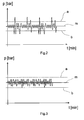
- FIG. 3 shows the signals of the bellows pressure sensor 17 on the front axle 15 when driving the trailer 10 on a paved road with a flat road.
- the amplitude of the Bellows pressure signal fluctuates around an average m and within a corridor of upper limit a and lower limit b.
- the anti-lock function remains in a standard mode.
- the anti-lock function only allows little slip or no slip of the wheels.
- FIG. 2 shows the waveform for the bellows pressure sensor 17 when driving off-road, especially on uneven, loose ground.
- the amplitude of the bellows pressure varies as in FIG. 3 around the mean m. Over time, however, the upper limit a is exceeded several times. Likewise, the lower limit b is exceeded several times.
- the control unit 12 counts the overshoots and undershoots of the limit values a, b per unit of time. If a defined number of overshoots and undershoots per unit of time is exceeded, the control unit 12 recognizes the off-road drive and switches the anti-lock function into an off-road mode. In off-road mode, the anti-lock function allows a higher slip, in extreme cases, any slip. This corresponds to a deactivated anti-lock function.
- Switching from standard mode to off-road mode takes place automatically in control unit 12.
- the driver of the tractor does not have to intervene. Switching takes place, for example, when the limit values a and b exceed 10 times and exceed the limit values per minute.
- Switching from off-road mode to standard mode is also automatic and dependent on the signal from the bellows pressure sensor 17. For example, it switches if less within the last minute when 5 exceedances and underruns of limit values a and b have occurred.
- a longitudinal acceleration sensor 20 Connected to the control unit 12 is still a longitudinal acceleration sensor 20. This measures the longitudinal acceleration of the trailer vehicle 10.
- the signal of the longitudinal acceleration sensor 20 can also be used as a measure of the slope of the road or the ground. As soon as the trailer 10 travels on a slope downhill or downhill, the gravitational acceleration for the longitudinal acceleration sensor 20 is detectable, depending on the angle of inclination. Based on the signals of the wheel speed sensors 13, 14, the acceleration in the longitudinal direction of the trailer 10 can be deducted.
- the control unit 12 utilizes the signals of the longitudinal acceleration sensor 20 in such a way that, starting from a downhill gradient of 3% or more, in particular 5% or more (ie downhill), the terrain mode switches into a sharper off-road mode of the anti-lock function.
- the anti-lock function allows for greater slip than in off-road mode.
- the anti-lock function is turned off. Switching to the sharpened off-road mode is only possible if the off-road mode is already switched on.
- the trailer vehicle 10 is preferably intended for operation with an agricultural or forestry tractor and thus for use also or predominantly off-paved roads.
Landscapes
- Engineering & Computer Science (AREA)
- Transportation (AREA)
- Mechanical Engineering (AREA)
- Microelectronics & Electronic Packaging (AREA)
- Regulating Braking Force (AREA)
Abstract
Description
- Die Erfindung betrifft ein Verfahren zur Steuerung eines elektronischen Bremssystems in einem Fahrzeug, insbesondere in einem Anhängefahrzeug, mit einer Antiblockierfunktion, wobei das Fahrzeug wenigstens einen Achslastsensor aufweist. Weiterhin betrifft die Erfindung ein elektronisches Bremssystem, ein Steuergerät zur Durchführung des Verfahrens und ein Fahrzeug mit elektronischem Bremssystem.
- Nutzfahrzeuge mit pneumatischem Bremssystem weisen daneben ein elektronisches Bremssystem auf, dessen Steuergerät mit angeschlossenen Raddrehzahlsensoren eine Antiblockierfunktion steuert. Blockierende Räder können so wirksam verhindert werden. Bekannt ist auch die Verwendung von Sensoren zur Ermittlung der Achslast in Fahrzeugen mit elektronischem Bremssystem.
- Die beschriebene Antiblockierfunktion ist zur Verkürzung eines Bremsweges geeignet bei der Fahrt auf festem, ebenem Untergrund. Im Gelände, d. h. auf unebenem, losem Untergrund führt die Antiblockierfunktion eher zu einem längeren Bremsweg. Bei unebenem, losem Untergrund kann ein Schlupf der Räder zu einem kürzerem Bremsweg verhelfen, da sich durch den Schlupf ein Keil aus Untergrundmaterial vor dem betreffenden Rad aufbaut. Es ist deshalb grundsätzlich bekannt, die Antiblockierfunktion bei Fahrten auf einem Untergrund, der nicht fest und eben ist, abzuschalten. Hierzu muss der Fahrer einen Schalter im Zugfahrzeug oder Anhängefahrzeug bedienen.
- Für den Betrieb mit einem Schlepper gibt es Anhängefahrzeuge mit eigenem elektronischem Bremssystem und Antiblockierfunktion. Zur Deaktivierung der Antiblockierfunktion müsste der Fahrer einen Schalter manuell betätigen. Vergisst der Fahrer dies, kann es zu Bremswegverlängerungen kommen.
- Aufgabe der vorliegenden Erfindung ist die automatische Erkennung einer Geländefahrt, so dass die Antiblockierfunktion ohne Eingriff des Fahrers aus dem Standardmodus in den Geländemodus wechseln kann.
- Zur Lösung der Aufgabe weist das erfindungsgemäße Verfahren die Merkmale des Anspruchs 1 auf. Die Antiblockierfunktion arbeitet in wenigstens zwei verschiedenen Modi, nämlich in einem Standardmodus zumindest bei festem, ebenem Untergrund und in einem Geländemodus im Übrigen, Es werden Signale des Achslastsensors ausgewertet, um die Beschaffenheit des Untergrunds zu erkennen. Die Antiblockierfunktion schaltet in Abhängigkeit von den Signalen des Achslastsensors vom Standardmodus in den Geländemodus und umgekehrt, wobei die Antiblockierfunktion im Geländemodus einen größeren Schlupf zulässt als im Standardmodus.
- Der Begriff "Achslastsensor" ist hier grundsätzlich im weitesten Sinne zu verstehen. Relevant sind alle Sensoren, die einen Druck oder Weg oder eine andere Größe aufnehmen können, die in einer Beziehung zur Achslast oder zur Änderung der Achslast auf unebenem Untergrund steht. Insbesondere handelt es sich um bekannte Achslastsensoren, beispielsweise einen Balgdrucksensor als Teil einer pneumatischen Federung, einen Drucksensor als Teil einer hydraulischen Federung oder einen Wegsensor als Teil einer mechanischen Federung.
- Das Signal des Achslastsensors ist vom Untergrund abhängig. Amplitude und Frequenz auf glatter, fester Straße unterscheiden sich maßgeblich von Amplitude und Frequenz des Signals auf losem, ungleichmäßigem Untergrund. Eine Unterscheidung ist durch Mustererkennung leicht möglich.
- Grundsätzlich soll die Antiblockierfunktion im Geländemodus lediglich einen etwas größeren Schlupf zulassen als im Standardmodus. Erfindungsgemäß ist aber auch ein Geländemodus mit extrem reduzierter Antiblockierfunktion, nämlich mit beliebigem Schlupf oder abgeschalteter Antiblockierfunktion.
- Erfindungsgemäß können Signale eines Neigungssensors ausgewertet werden, um eine Talfahrt zu erkennen. Nach Erkennung der Talfahrt, insbesondere von 5% oder mehr Neigung, schaltet die Antiblockierfunktion in einen verschärften Geländemodus. In diesem verschärften Geländemodus lässt die Antiblockierfunktion einen größeren Schlupf zu als im Geländemodus. Vorzugsweise lässt die Antiblockierfunktion im verschärften Geländemodus beliebigen Schlupf zu oder die Antiblockierfunktion wird abgeschaltet.
- Gegenstand der Erfindung ist auch ein elektronisches Bremssystem mit den Merkmalen des Anspruchs 5. Das System ist insbesondere für ein Anhängefahrzeug vorgesehen und weist eine Antiblockierfunktion und wenigstens einen Achslastsensor auf. Die Antiblockierfunktion weist wenigstens zwei verschiedenen Modi auf, nämlich einen Standardmodus für festen, ebenen Untergrund und einen Geländemodus. Die Signale des Achslastsensors sind auswertbar, um die Beschaffenheit des Untergrunds zu erkennen. Die Antiblockierfunktion schaltet in Abhängigkeit von den Signalen des Achslastsensors vom Standardmodus in den Geländemodus und umgekehrt, wobei die Antiblockierfunktion im Geländemodus einen größeren Schlupf zulässt als im Standardmodus.
- Typischerweise enthält ein elektronisches Bremssystem für Fahrzeuge ein Steuergerät, in dem die erforderlichen Funktionen durch verdrahtete Bauteile oder durch Software realisiert sind. An das Steuergerät sind die für die Funktion wichtigen Sensoren angeschlossen. Im Hinblick auf die Antiblockierfunktion handelt es sich um Raddrehzahlsensoren. Zusätzlich kann der Achslastsensor an das Steuergerät angeschlossen sein.
- Vorteilhafterweise ist der Achslastsensor ein in eine pneumatische oder hydraulische Federung integrierter Drucksensor, beispielsweise ein Balgdrucksensor in einer pneumatischen Federung. Sofern eine mechanische Federung im Fahrzeug vorhanden ist, kann der Achslastsensor darin integriert sein, beispielsweise ein Wegsensor. Schließlich kann der Achslastsensor auch ein von einer Federung unabhängiger, externer Sensor sein.
- Nach einem weiteren Gedanken der Erfindung wertet das elektronische Bremssystem auch die Signale eines Neigungssensors für die Erkennung einer Talfahrt aus. Bei Erkennung der Talfahrt, insbesondere mit einer Neigung von 5% oder mehr, schaltet die Antiblockierfunktion in einen verschärften Geländemodus, wobei die Antiblockierfunktion im verschärften Geländemodus einen größeren Schlupf zulässt als im Geländemodus.
- Vorteilhafterweise ist der Neigungssensor ein Längsbeschleunigungssensor. Je stärker das Fahrzeug in Fahrtrichtung abwärts geneigt ist, umso höhere Werte zeigt der Längsbeschleunigungssensor aufgrund der Erdbeschleunigung an.
- Gegenstand der Erfindung ist auch ein Steuergerät zur Durchführung des Verfahrens nach einem der Ansprüche 1 bis 4. Das Steuergerät kann die in einem elektronischen Bremssystem üblichen Funktionen aufweisen und zur Durchführung des erfindungsgemäßen Verfahrens entsprechend programmiert sein und/oder geeignete Bauteile aufweisen.
- Schließlich ist Gegenstand der Erfindung auch ein Fahrzeug mit einem System nach einem der Ansprüche 5 bis 10, insbesondere ein Anhängefahrzeug. Vorzugsweise ist das System in einem von einem Schlepper gezogenen Anhängefahrzeug installiert, insbesondere in einem Anhängefahrzeug, wie es in der Landwirtschaft, in der Forstwirtschaft oder speziell im Gelände eingesetzt wird.
- Weitere Merkmale der Erfindung ergeben sich aus der Beschreibung im Übrigen und aus den Ansprüchen. Vorteilhafte Ausführungsbeispiele der Erfindung werden nachfolgend anhand von Zeichnungen näher erläutert. Es zeigen:
-
Figur 1 eine schematische Darstellung eines Anhängefahrzeugs mit elektronischem Bremssystem, -
Figur 2 den Verlauf eines Achslastsignals bei Bewegung des Anhängefahrzeugs im Gelände, -
Figur 3 den Verlauf des Achslastsignals bei Bewegung des Anhängefahrzeugs auf fester, ebener Straße. - Ein Anhängefahrzeug 10 mit Deichsel 11 weist nicht näher gezeigte pneumatische Bremsen in Verbindung mit einem elektronischen Bremssystem auf. Wesentlicher Bestandteil des Letzteren ist ein Steuergerät 12. Dieses empfängt Signale von Raddrehzahlsensoren 13, 14 an Rädern von Vorderachse 15 und Hinterachse 16 und regelt den Bremsdruck. Hierzu angesteuerte pneumatische Elemente sind nicht gezeigt. Das Steuergerät 12 regelt auch eine Antiblockierfunktion, mit der ein größerer Schlupf bzw. ein Blockieren der Räder beim Bremsen begrenzt oder vermieden werden soll.
- Das Anhängefahrzeug 10 ist mit einer pneumatischen Federung versehen. In diese integriert sind zwei Balgdrucksensoren 17, 18, einer im Bereich der Hinterachse 16 und einer im Bereich der Vorderachse 15. Die Balgdrucksensoren übermitteln ihre Signale ebenfalls an das Steuergerät 12. Die Signale repräsentieren die jeweils wirksame Achslast. Entsprechend haben die Balgdrucksensoren 17, 18 hier die Funktion von Achslastsensoren.
- Das Steuergerät 12 weist eine genormte Schnittstelle 19 zum Anschluss an ein nicht gezeigtes Motorfahrzeug auf. Über die Schnittstelle 19 ist insbesondere eine Versorgung mit elektrischem Strom vorgesehen. Auch kann eine Datenverbindung integriert sein. Die Signale zumindest eines der Balgdrucksensoren 17, 18 werden im Steuergerät 12 ausgewertet und zur Steuerung der Antiblockierfunktion verarbeitet.
Figur 3 zeigt die Signale des Balgdrucksensors 17 an der Vorderachse 15 bei Fahrt des Anhängefahrzeugs 10 auf einer befestigten Straße mit ebener Fahrbahn. Die Amplitude des Balgdrucksignals schwankt um einen Mittelwert m und innerhalb eines Korridors aus oberem Grenzwert a und unterem Grenzwert b. Bei diesem Signalverlauf bleibt die Antiblockierfunktion in einem Standardmodus. Vorzugsweise lässt die Antiblockierfunktion im Standardmodus nur geringen Schlupf oder keinen Schlupf der Räder zu. -
Figur 2 zeigt den Signalverlauf für den Balgdrucksensor 17 bei Fahrt im Gelände, insbesondere auf unebenem, losem Untergrund. Die Amplitude des Balgdrucks schwankt wie inFigur 3 um den Mittelwert m. Im Zeitverlauf wird aber der obere Grenzwert a mehrfach überschritten. Ebenso wird der untere Grenzwert b mehrfach unterschritten. Mit geeigneter Software und/oder Hardware zählt das Steuergerät 12 die Überschreitungen und Unterschreitungen der Grenzwerte a, b pro Zeiteinheit. Sofern eine definierte Anzahl an Überschreitungen und Unterschreitungen pro Zeiteinheit überschritten wird, erkennt das Steuergerät 12 die Geländefahrt und schaltet die Antiblockierfunktion in einen Geländemodus. Im Geländemodus lässt die Antiblockierfunktion einen höheren Schlupf zu, im Extremfall einen beliebigen Schlupf. Dies entspricht einer abgeschalteten Antiblockierfunktion. - Bei höherem Schlupf bzw. abgeschalteter Antiblockierfunktion kann sich bei einer Vollbremsung im Gelände vor den Reifen ein Keil aus Untergrundmaterial aufbauen. Der Bremsweg ist dann kürzer als bei einer Vollbremsung im Gelände mit unbeschränkter Antiblockierfunktion.
- Die Umschaltung von Standardmodus in Geländemodus erfolgt automatisch im Steuergerät 12. Der Fahrer der Zugmaschine muss nicht eingreifen. Die Umschaltung erfolgt beispielsweise bei mehr als 10 Über- und Unterschreitungen der Grenzwerte a und b pro Minute.
- Das Umschalten vom Geländemodus in den Standardmodus erfolgt ebenfalls automatisch und in Abhängigkeit vom Signal des Balgdrucksensors 17. Beispielsweise wird umgeschaltet, sofern innerhalb der letzten Minute weniger als 5 Überschreitungen und Unterschreitungen der Grenzwerte a und b aufgetreten sind.
- An das Steuergerät 12 angeschlossen ist noch ein Längsbeschleunigungssensor 20. Dieser misst die Längsbeschleunigung des Anhängefahrzeugs 10. Das Signal des Längsbeschleunigungssensors 20 kann auch als Maß für die Steigung der Fahrbahn oder des Untergrunds verwendet werden. Sobald das Anhängefahrzeug 10 auf einer Steigung talwärts oder bergwärts fährt, ist die Erdbeschleunigung für den Längsbeschleunigungssensor 20 detektierbar, abhängig vom Neigungswinkel. Anhand der Signale der Raddrehzahlsensoren 13, 14 kann die Beschleunigung in Längsrichtung des Anhängefahrzeugs 10 herausgerechnet werden.
- Das Steuergerät 12 verwertet die Signale des Längsbeschleunigungssensors 20 derart, dass ab einer talwärts gerichteten Steigung von 3 % oder mehr, insbesondere von 5 % oder mehr (also bei Talfahrt), aus dem Geländemodus in einen verschärften Geländemodus der Antiblockierfunktion geschaltet wird. In diesem verschärften Geländemodus lässt die Antiblockierfunktion einen größeren Schlupf zu als im Geländemodus. Vorzugsweise wird die Antiblockierfunktion abgeschaltet. Die Umschaltung in den verschärften Geländemodus erfolgt nur, wenn bereits der Geländemodus eingeschaltet ist.
- Das Anhängefahrzeug 10 ist vorzugsweise für den Betrieb mit einer landwirtschaftlichen oder forstwirtschaftlichen Zugmaschine und demnach zur Benutzung auch oder überwiegend abseits befestigter Straßen vorgesehen.
Claims (12)
- Verfahren zur Steuerung eines elektronischen Bremssystems in einem Fahrzeug mit einer Antiblockierfunktion, insbesondere in einem Anhängefahrzeug (10), wobei das Fahrzeug wenigstens einen Achslastsensor aufweist, dadurch gekennzeichnet, dass die Antiblockierfunktion in wenigstens zwei verschiedenen Modi arbeitet, nämlich in einem Standardmodus zumindest bei festem, ebenem Untergrund und in einem Geländemodus im Übrigen, dass Signale des Achslastsensors ausgewertet werden, um die Beschaffenheit des Untergrunds zu erkennen, und dass die Antiblockierfunktion in Abhängigkeit von den Signalen des Achslastsensors vom Standardmodus in den Geländemodus und umgekehrt schaltet, wobei die Antiblockierfunktion im Geländemodus einen größeren Schlupf zulässt als im Standardmodus.
- Verfahren nach Anspruch 1, dadurch gekennzeichnet, dass die Antiblockierfunktion im Geländemodus beliebigen Schlupf zulässt oder abgeschaltet wird.
- Verfahren nach Anspruch 1, dadurch gekennzeichnet, dass Signale eines Neigungssensors ausgewertet werden, um eine Talfahrt zu erkennen, und dass nach Erkennung einer Talfahrt mit insbesondere einer Neigung von 5% oder mehr die Antiblockierfunktion in einen verschärften Geländemodus schaltet, wobei die Antiblockierfunktion im verschärften Geländemodus einen größeren Schlupf zulässt als im Geländemodus.
- Verfahren nach Anspruch 3, dadurch gekennzeichnet, dass die Antiblockierfunktion im verschärften Geländemodus beliebigen Schlupf zulässt oder abgeschaltet wird.
- Elektronisches Bremssystem, insbesondere für ein Anhängefahrzeug (10), mit einer Antiblockierfunktion und wenigstens einem Achslastsensor, dadurch gekennzeichnet, dass die Antiblockierfunktion wenigstens zwei verschiedene Modi aufweist, nämlich einen Standardmodus zumindest für festen, ebenen Untergrund und einen Geländemodus im Übrigen, dass Signale des Achslastsensors auswertbar sind, um die Beschaffenheit des Untergrunds zu erkennen, und dass die Antiblockierfunktion in Abhängigkeit von den Signalen des Achslastsensors vom Standardmodus in den Geländemodus und umgekehrt schaltet, wobei die Antiblockierfunktion im Geländemodus einen größeren Schlupf zulässt als im Standardmodus.
- System nach Anspruch, dadurch gekennzeichnet, dass der Achslastsensor ein in eine pneumatische oder hydraulische Federung integrierter Drucksensor (17,18) ist.
- System nach Anspruch 5, dadurch gekennzeichnet, dass der Achslastsensor ein in eine mechanische Federung integrierter Sensor ist, insbesondere ein Wegsensor.
- System nach Anspruch 5, dadurch gekennzeichnet, dass der Achslastsensor ein von einer Federung unabhängiger, externer Sensor ist.
- System nach Anspruch 5 oder einem der weiteren Ansprüche, gekennzeichnet durch einen Neigungssensor, dessen Signale für die Erkennung einer Talfahrt ausgewertet werden, und dass nach Erkennung einer Talfahrt mit einer Neigung von insbesondere 5% oder mehr die Antiblockierfunktion in einen verschärften Geländemodus schaltet, wobei die Antiblockierfunktion im verschärften Geländemodus einen größeren Schlupf zulässt als im Geländemodus.
- System nach Anspruch 9, dadurch gekennzeichnet, dass der Neigungssensor ein Längsbeschleunigungssensor (20) ist.
- Steuergerät zur Durchführung des Verfahrens nach einem der Ansprüche 1 bis 4.
- Fahrzeug mit einem System nach einem der Ansprüche 5 bis 10, insbesondere Anhängefahrzeug (10).
Applications Claiming Priority (1)
| Application Number | Priority Date | Filing Date | Title |
|---|---|---|---|
| DE102013016087.1A DE102013016087A1 (de) | 2013-09-27 | 2013-09-27 | Verfahren und System zur Steuerung eines elektronischen Bremssystems |
Publications (2)
| Publication Number | Publication Date |
|---|---|
| EP2853452A1 true EP2853452A1 (de) | 2015-04-01 |
| EP2853452B1 EP2853452B1 (de) | 2019-04-10 |
Family
ID=51210946
Family Applications (1)
| Application Number | Title | Priority Date | Filing Date |
|---|---|---|---|
| EP14002418.3A Not-in-force EP2853452B1 (de) | 2013-09-27 | 2014-07-14 | Verfahren und System zur Steuerung eines elektronischen Bremssystems |
Country Status (2)
| Country | Link |
|---|---|
| EP (1) | EP2853452B1 (de) |
| DE (1) | DE102013016087A1 (de) |
Cited By (1)
| Publication number | Priority date | Publication date | Assignee | Title |
|---|---|---|---|---|
| WO2017157502A1 (de) * | 2016-03-18 | 2017-09-21 | Wabco Gmbh | Elektronisches bremssystem für ein anhängerfahrzeug |
Families Citing this family (1)
| Publication number | Priority date | Publication date | Assignee | Title |
|---|---|---|---|---|
| GB2642315A (en) * | 2024-07-02 | 2026-01-07 | Jaguar Land Rover Ltd | Control system for an anti-lock braking system |
Citations (6)
| Publication number | Priority date | Publication date | Assignee | Title |
|---|---|---|---|---|
| EP0425810A1 (de) * | 1989-10-31 | 1991-05-08 | MAN Nutzfahrzeuge Aktiengesellschaft | Kraftfahrzeug mit verschiedenen Bremsenbetätigungsprogrammen |
| EP0475010A2 (de) * | 1990-09-03 | 1992-03-18 | WABCO GmbH | Regellogik für eine blockiergeschützte Fahrzeugbremsanlage |
| GB2353573A (en) * | 1999-08-24 | 2001-02-28 | Bosch Gmbh Robert | Adjusting the braking action at the wheels of a motor vehicle |
| DE102008054476A1 (de) * | 2008-12-10 | 2010-06-17 | Zf Friedrichshafen Ag | Verfahren zur Ermittlung des Fahrbahnzustands eines von einem Kraftfahrzeug befahrenen Streckenabschnitts |
| DE102011112422A1 (de) * | 2011-09-03 | 2013-03-07 | Volkswagen Aktiengesellschaft | Verfahren für ein Fahrzeug-Sicherheitssystem und entsprechende Vorrichtung |
| US20130211683A1 (en) * | 2012-02-09 | 2013-08-15 | Arvinmeritor Technology, Llc | Method of controlling a brake system of a vehicle |
Family Cites Families (6)
| Publication number | Priority date | Publication date | Assignee | Title |
|---|---|---|---|---|
| DE3933652A1 (de) * | 1989-10-09 | 1991-04-11 | Bosch Gmbh Robert | Antiblockierregelsystem und antriebsschlupfregelsystem |
| DE19602170A1 (de) * | 1996-01-23 | 1997-07-24 | Teves Gmbh Alfred | Verfahren zur Bestimmung von Fahrwegbedingungen |
| DE10253536A1 (de) * | 2002-11-16 | 2004-05-27 | Wabco Gmbh & Co. Ohg | ABS-Regellogik mit Gelände-Modul |
| DE102006024617A1 (de) * | 2006-05-26 | 2007-11-29 | Volkswagen Ag | Antiblockiersystem, insbesondere für geländegängige Fahrzeuge |
| DE102008038037A1 (de) * | 2008-08-16 | 2010-02-18 | Wabco Gmbh | Verfahren und Vorrichtung zur fahrdynamischen Regelung eines Fahrzeugs |
| DE102010007409B4 (de) * | 2010-02-10 | 2012-01-26 | Knorr-Bremse Systeme für Nutzfahrzeuge GmbH | Verfahren zum Betreiben einer Bremsschlupfregelung eines Bremssystems eines Fahrzeugs |
-
2013
- 2013-09-27 DE DE102013016087.1A patent/DE102013016087A1/de not_active Withdrawn
-
2014
- 2014-07-14 EP EP14002418.3A patent/EP2853452B1/de not_active Not-in-force
Patent Citations (6)
| Publication number | Priority date | Publication date | Assignee | Title |
|---|---|---|---|---|
| EP0425810A1 (de) * | 1989-10-31 | 1991-05-08 | MAN Nutzfahrzeuge Aktiengesellschaft | Kraftfahrzeug mit verschiedenen Bremsenbetätigungsprogrammen |
| EP0475010A2 (de) * | 1990-09-03 | 1992-03-18 | WABCO GmbH | Regellogik für eine blockiergeschützte Fahrzeugbremsanlage |
| GB2353573A (en) * | 1999-08-24 | 2001-02-28 | Bosch Gmbh Robert | Adjusting the braking action at the wheels of a motor vehicle |
| DE102008054476A1 (de) * | 2008-12-10 | 2010-06-17 | Zf Friedrichshafen Ag | Verfahren zur Ermittlung des Fahrbahnzustands eines von einem Kraftfahrzeug befahrenen Streckenabschnitts |
| DE102011112422A1 (de) * | 2011-09-03 | 2013-03-07 | Volkswagen Aktiengesellschaft | Verfahren für ein Fahrzeug-Sicherheitssystem und entsprechende Vorrichtung |
| US20130211683A1 (en) * | 2012-02-09 | 2013-08-15 | Arvinmeritor Technology, Llc | Method of controlling a brake system of a vehicle |
Cited By (1)
| Publication number | Priority date | Publication date | Assignee | Title |
|---|---|---|---|---|
| WO2017157502A1 (de) * | 2016-03-18 | 2017-09-21 | Wabco Gmbh | Elektronisches bremssystem für ein anhängerfahrzeug |
Also Published As
| Publication number | Publication date |
|---|---|
| DE102013016087A1 (de) | 2015-04-02 |
| EP2853452B1 (de) | 2019-04-10 |
Similar Documents
| Publication | Publication Date | Title |
|---|---|---|
| EP2634073B1 (de) | Antriebsachsen-Achslastbeeinflussung bei Fahrzeugzügen | |
| EP2404800B1 (de) | Verfahren und Vorrichtung zur Durchführung einer Bremsenprüfung an Anhänger- und / oder Aufliegerfahrzeugen | |
| EP2138333B1 (de) | Lastzug | |
| DE102020126627A1 (de) | Bestimmen der verstärkung der anhängerbremse | |
| DE112018000586T5 (de) | Steuerung der bewegung eines fahrzeugs | |
| DE102017111054B4 (de) | Verfahren zum Betreiben eines Federungssystems eines Kraftfahrzeugs, Steuergerät, Federungssystem sowie Kraftfahrzeug | |
| EP3689698B2 (de) | Schlepper | |
| WO1997028017A1 (de) | Fahrdynamik-regelungsverfahren und -vorrichtung | |
| DE102015221833A1 (de) | Fahrzeuglastinformationssystem zur Bestimmung einer Starßenneigung und einer Last bei am Fahrzeug angefügtem Anhänger | |
| DE102012000784A1 (de) | Stabilisierung eines Fahrzeuggespanns | |
| WO2013029703A2 (de) | Verfahren zur warnung des fahrers eines fahrzeuges vor einem drohenden umkippen und steuerungseinrichtung dafür | |
| EP3365205B1 (de) | Verfahren zur ansteuerung von bremsen | |
| DE102011108218A1 (de) | Bodenfreiheitsassistent für ein Kraftfahrzeug | |
| EP3515796B1 (de) | Verfahren zur erkennung und/oder steuerung eines ankupplungsvorgangs zwischen einem zugfahrzeug und einem fahrzeuganhänger | |
| DE102015115851A1 (de) | Verfahren zum Betreiben eines Gespanns | |
| DE19958772A1 (de) | Verfahren und Vorrichtung zur Antriebsschlupfregelung (ASR) eines Kraftfahrzeugs in Abhängigkeit von Kurvenradius und Querbeschleunigung | |
| DE102004010233B4 (de) | Verfahren zur Abbremsung eines Fahrzeuges | |
| DE102011083610A1 (de) | Geschwindigkeitssteuerung für ein Kraftfahrzeug | |
| EP2853452B1 (de) | Verfahren und System zur Steuerung eines elektronischen Bremssystems | |
| DE102009035525A1 (de) | Verfahren zur Traktions-Erhöhung bei einem Zugfahrzeug mit Sattelanhänger | |
| WO2023025528A1 (de) | Unterstützungsverfahren und unterstützungsvorrichtung für bergauf-anfahrvorgänge eines fahrzeuggespanns, fahrzeuggespann umfassend die unterstützungsvorrichtung | |
| EP3988415A1 (de) | Verfahren zum betreiben eines assistenzsystems eines kraftfahrzeugs, sowie assistenzsystem | |
| DE102012023775A1 (de) | Verfahren zur Verkleinerung des Wendekreises eines Lastzugs und Lastzug, der verfahrensgemäß betreibbar ist | |
| DE102023002654A1 (de) | Verfahren zum Führen eines Kraftfahrzeugs sowie korrespondierendes Kraftfahrzeug | |
| DE102018132573A1 (de) | Verfahren zur automatischen Aktivierung einer Parkbremse eines einspurigen Kraftfahrzeugs |
Legal Events
| Date | Code | Title | Description |
|---|---|---|---|
| PUAI | Public reference made under article 153(3) epc to a published international application that has entered the european phase |
Free format text: ORIGINAL CODE: 0009012 |
|
| 17P | Request for examination filed |
Effective date: 20140714 |
|
| AK | Designated contracting states |
Kind code of ref document: A1 Designated state(s): AL AT BE BG CH CY CZ DE DK EE ES FI FR GB GR HR HU IE IS IT LI LT LU LV MC MK MT NL NO PL PT RO RS SE SI SK SM TR |
|
| AX | Request for extension of the european patent |
Extension state: BA ME |
|
| R17P | Request for examination filed (corrected) |
Effective date: 20151001 |
|
| RBV | Designated contracting states (corrected) |
Designated state(s): AL AT BE BG CH CY CZ DE DK EE ES FI FR GB GR HR HU IE IS IT LI LT LU LV MC MK MT NL NO PL PT RO RS SE SI SK SM TR |
|
| STAA | Information on the status of an ep patent application or granted ep patent |
Free format text: STATUS: EXAMINATION IS IN PROGRESS |
|
| 17Q | First examination report despatched |
Effective date: 20171214 |
|
| GRAP | Despatch of communication of intention to grant a patent |
Free format text: ORIGINAL CODE: EPIDOSNIGR1 |
|
| STAA | Information on the status of an ep patent application or granted ep patent |
Free format text: STATUS: GRANT OF PATENT IS INTENDED |
|
| INTG | Intention to grant announced |
Effective date: 20190130 |
|
| GRAS | Grant fee paid |
Free format text: ORIGINAL CODE: EPIDOSNIGR3 |
|
| GRAA | (expected) grant |
Free format text: ORIGINAL CODE: 0009210 |
|
| STAA | Information on the status of an ep patent application or granted ep patent |
Free format text: STATUS: THE PATENT HAS BEEN GRANTED |
|
| AK | Designated contracting states |
Kind code of ref document: B1 Designated state(s): AL AT BE BG CH CY CZ DE DK EE ES FI FR GB GR HR HU IE IS IT LI LT LU LV MC MK MT NL NO PL PT RO RS SE SI SK SM TR |
|
| REG | Reference to a national code |
Ref country code: GB Ref legal event code: FG4D Free format text: NOT ENGLISH |
|
| REG | Reference to a national code |
Ref country code: CH Ref legal event code: EP Ref country code: AT Ref legal event code: REF Ref document number: 1118246 Country of ref document: AT Kind code of ref document: T Effective date: 20190415 |
|
| REG | Reference to a national code |
Ref country code: IE Ref legal event code: FG4D Free format text: LANGUAGE OF EP DOCUMENT: GERMAN |
|
| REG | Reference to a national code |
Ref country code: DE Ref legal event code: R096 Ref document number: 502014011349 Country of ref document: DE |
|
| REG | Reference to a national code |
Ref country code: NL Ref legal event code: MP Effective date: 20190410 |
|
| REG | Reference to a national code |
Ref country code: LT Ref legal event code: MG4D |
|
| PG25 | Lapsed in a contracting state [announced via postgrant information from national office to epo] |
Ref country code: NL Free format text: LAPSE BECAUSE OF FAILURE TO SUBMIT A TRANSLATION OF THE DESCRIPTION OR TO PAY THE FEE WITHIN THE PRESCRIBED TIME-LIMIT Effective date: 20190410 |
|
| PG25 | Lapsed in a contracting state [announced via postgrant information from national office to epo] |
Ref country code: NO Free format text: LAPSE BECAUSE OF FAILURE TO SUBMIT A TRANSLATION OF THE DESCRIPTION OR TO PAY THE FEE WITHIN THE PRESCRIBED TIME-LIMIT Effective date: 20190710 Ref country code: FI Free format text: LAPSE BECAUSE OF FAILURE TO SUBMIT A TRANSLATION OF THE DESCRIPTION OR TO PAY THE FEE WITHIN THE PRESCRIBED TIME-LIMIT Effective date: 20190410 Ref country code: PT Free format text: LAPSE BECAUSE OF FAILURE TO SUBMIT A TRANSLATION OF THE DESCRIPTION OR TO PAY THE FEE WITHIN THE PRESCRIBED TIME-LIMIT Effective date: 20190910 Ref country code: HR Free format text: LAPSE BECAUSE OF FAILURE TO SUBMIT A TRANSLATION OF THE DESCRIPTION OR TO PAY THE FEE WITHIN THE PRESCRIBED TIME-LIMIT Effective date: 20190410 Ref country code: LT Free format text: LAPSE BECAUSE OF FAILURE TO SUBMIT A TRANSLATION OF THE DESCRIPTION OR TO PAY THE FEE WITHIN THE PRESCRIBED TIME-LIMIT Effective date: 20190410 Ref country code: ES Free format text: LAPSE BECAUSE OF FAILURE TO SUBMIT A TRANSLATION OF THE DESCRIPTION OR TO PAY THE FEE WITHIN THE PRESCRIBED TIME-LIMIT Effective date: 20190410 Ref country code: AL Free format text: LAPSE BECAUSE OF FAILURE TO SUBMIT A TRANSLATION OF THE DESCRIPTION OR TO PAY THE FEE WITHIN THE PRESCRIBED TIME-LIMIT Effective date: 20190410 Ref country code: SE Free format text: LAPSE BECAUSE OF FAILURE TO SUBMIT A TRANSLATION OF THE DESCRIPTION OR TO PAY THE FEE WITHIN THE PRESCRIBED TIME-LIMIT Effective date: 20190410 |
|
| PG25 | Lapsed in a contracting state [announced via postgrant information from national office to epo] |
Ref country code: GR Free format text: LAPSE BECAUSE OF FAILURE TO SUBMIT A TRANSLATION OF THE DESCRIPTION OR TO PAY THE FEE WITHIN THE PRESCRIBED TIME-LIMIT Effective date: 20190711 Ref country code: LV Free format text: LAPSE BECAUSE OF FAILURE TO SUBMIT A TRANSLATION OF THE DESCRIPTION OR TO PAY THE FEE WITHIN THE PRESCRIBED TIME-LIMIT Effective date: 20190410 Ref country code: PL Free format text: LAPSE BECAUSE OF FAILURE TO SUBMIT A TRANSLATION OF THE DESCRIPTION OR TO PAY THE FEE WITHIN THE PRESCRIBED TIME-LIMIT Effective date: 20190410 Ref country code: RS Free format text: LAPSE BECAUSE OF FAILURE TO SUBMIT A TRANSLATION OF THE DESCRIPTION OR TO PAY THE FEE WITHIN THE PRESCRIBED TIME-LIMIT Effective date: 20190410 Ref country code: BG Free format text: LAPSE BECAUSE OF FAILURE TO SUBMIT A TRANSLATION OF THE DESCRIPTION OR TO PAY THE FEE WITHIN THE PRESCRIBED TIME-LIMIT Effective date: 20190710 |
|
| PG25 | Lapsed in a contracting state [announced via postgrant information from national office to epo] |
Ref country code: IS Free format text: LAPSE BECAUSE OF FAILURE TO SUBMIT A TRANSLATION OF THE DESCRIPTION OR TO PAY THE FEE WITHIN THE PRESCRIBED TIME-LIMIT Effective date: 20190810 |
|
| REG | Reference to a national code |
Ref country code: DE Ref legal event code: R097 Ref document number: 502014011349 Country of ref document: DE |
|
| PG25 | Lapsed in a contracting state [announced via postgrant information from national office to epo] |
Ref country code: SK Free format text: LAPSE BECAUSE OF FAILURE TO SUBMIT A TRANSLATION OF THE DESCRIPTION OR TO PAY THE FEE WITHIN THE PRESCRIBED TIME-LIMIT Effective date: 20190410 Ref country code: RO Free format text: LAPSE BECAUSE OF FAILURE TO SUBMIT A TRANSLATION OF THE DESCRIPTION OR TO PAY THE FEE WITHIN THE PRESCRIBED TIME-LIMIT Effective date: 20190410 Ref country code: CZ Free format text: LAPSE BECAUSE OF FAILURE TO SUBMIT A TRANSLATION OF THE DESCRIPTION OR TO PAY THE FEE WITHIN THE PRESCRIBED TIME-LIMIT Effective date: 20190410 Ref country code: DK Free format text: LAPSE BECAUSE OF FAILURE TO SUBMIT A TRANSLATION OF THE DESCRIPTION OR TO PAY THE FEE WITHIN THE PRESCRIBED TIME-LIMIT Effective date: 20190410 Ref country code: EE Free format text: LAPSE BECAUSE OF FAILURE TO SUBMIT A TRANSLATION OF THE DESCRIPTION OR TO PAY THE FEE WITHIN THE PRESCRIBED TIME-LIMIT Effective date: 20190410 |
|
| PLBE | No opposition filed within time limit |
Free format text: ORIGINAL CODE: 0009261 |
|
| STAA | Information on the status of an ep patent application or granted ep patent |
Free format text: STATUS: NO OPPOSITION FILED WITHIN TIME LIMIT |
|
| PG25 | Lapsed in a contracting state [announced via postgrant information from national office to epo] |
Ref country code: IT Free format text: LAPSE BECAUSE OF FAILURE TO SUBMIT A TRANSLATION OF THE DESCRIPTION OR TO PAY THE FEE WITHIN THE PRESCRIBED TIME-LIMIT Effective date: 20190410 Ref country code: SM Free format text: LAPSE BECAUSE OF FAILURE TO SUBMIT A TRANSLATION OF THE DESCRIPTION OR TO PAY THE FEE WITHIN THE PRESCRIBED TIME-LIMIT Effective date: 20190410 Ref country code: MC Free format text: LAPSE BECAUSE OF FAILURE TO SUBMIT A TRANSLATION OF THE DESCRIPTION OR TO PAY THE FEE WITHIN THE PRESCRIBED TIME-LIMIT Effective date: 20190410 |
|
| REG | Reference to a national code |
Ref country code: CH Ref legal event code: PL |
|
| 26N | No opposition filed |
Effective date: 20200113 |
|
| PG25 | Lapsed in a contracting state [announced via postgrant information from national office to epo] |
Ref country code: TR Free format text: LAPSE BECAUSE OF FAILURE TO SUBMIT A TRANSLATION OF THE DESCRIPTION OR TO PAY THE FEE WITHIN THE PRESCRIBED TIME-LIMIT Effective date: 20190410 |
|
| REG | Reference to a national code |
Ref country code: BE Ref legal event code: MM Effective date: 20190731 |
|
| PG25 | Lapsed in a contracting state [announced via postgrant information from national office to epo] |
Ref country code: CH Free format text: LAPSE BECAUSE OF NON-PAYMENT OF DUE FEES Effective date: 20190731 Ref country code: BE Free format text: LAPSE BECAUSE OF NON-PAYMENT OF DUE FEES Effective date: 20190731 Ref country code: LU Free format text: LAPSE BECAUSE OF NON-PAYMENT OF DUE FEES Effective date: 20190714 Ref country code: LI Free format text: LAPSE BECAUSE OF NON-PAYMENT OF DUE FEES Effective date: 20190731 Ref country code: SI Free format text: LAPSE BECAUSE OF FAILURE TO SUBMIT A TRANSLATION OF THE DESCRIPTION OR TO PAY THE FEE WITHIN THE PRESCRIBED TIME-LIMIT Effective date: 20190410 |
|
| PG25 | Lapsed in a contracting state [announced via postgrant information from national office to epo] |
Ref country code: IE Free format text: LAPSE BECAUSE OF NON-PAYMENT OF DUE FEES Effective date: 20190714 |
|
| REG | Reference to a national code |
Ref country code: AT Ref legal event code: MM01 Ref document number: 1118246 Country of ref document: AT Kind code of ref document: T Effective date: 20190714 |
|
| PG25 | Lapsed in a contracting state [announced via postgrant information from national office to epo] |
Ref country code: AT Free format text: LAPSE BECAUSE OF NON-PAYMENT OF DUE FEES Effective date: 20190714 |
|
| REG | Reference to a national code |
Ref country code: DE Ref legal event code: R081 Ref document number: 502014011349 Country of ref document: DE Owner name: ZF CV SYSTEMS EUROPE BV, BE Free format text: FORMER OWNER: WABCO GMBH, 30453 HANNOVER, DE Ref country code: DE Ref legal event code: R081 Ref document number: 502014011349 Country of ref document: DE Owner name: ZF CV SYSTEMS HANNOVER GMBH, DE Free format text: FORMER OWNER: WABCO GMBH, 30453 HANNOVER, DE |
|
| PG25 | Lapsed in a contracting state [announced via postgrant information from national office to epo] |
Ref country code: CY Free format text: LAPSE BECAUSE OF FAILURE TO SUBMIT A TRANSLATION OF THE DESCRIPTION OR TO PAY THE FEE WITHIN THE PRESCRIBED TIME-LIMIT Effective date: 20190410 |
|
| PG25 | Lapsed in a contracting state [announced via postgrant information from national office to epo] |
Ref country code: HU Free format text: LAPSE BECAUSE OF FAILURE TO SUBMIT A TRANSLATION OF THE DESCRIPTION OR TO PAY THE FEE WITHIN THE PRESCRIBED TIME-LIMIT; INVALID AB INITIO Effective date: 20140714 Ref country code: MT Free format text: LAPSE BECAUSE OF FAILURE TO SUBMIT A TRANSLATION OF THE DESCRIPTION OR TO PAY THE FEE WITHIN THE PRESCRIBED TIME-LIMIT Effective date: 20190410 |
|
| REG | Reference to a national code |
Ref country code: DE Ref legal event code: R081 Ref document number: 502014011349 Country of ref document: DE Owner name: ZF CV SYSTEMS EUROPE BV, BE Free format text: FORMER OWNER: ZF CV SYSTEMS HANNOVER GMBH, 30453 HANNOVER, DE |
|
| PG25 | Lapsed in a contracting state [announced via postgrant information from national office to epo] |
Ref country code: MK Free format text: LAPSE BECAUSE OF FAILURE TO SUBMIT A TRANSLATION OF THE DESCRIPTION OR TO PAY THE FEE WITHIN THE PRESCRIBED TIME-LIMIT Effective date: 20190410 |
|
| P01 | Opt-out of the competence of the unified patent court (upc) registered |
Effective date: 20230528 |
|
| PGFP | Annual fee paid to national office [announced via postgrant information from national office to epo] |
Ref country code: GB Payment date: 20240530 Year of fee payment: 11 |
|
| PGFP | Annual fee paid to national office [announced via postgrant information from national office to epo] |
Ref country code: FR Payment date: 20240611 Year of fee payment: 11 |
|
| PGFP | Annual fee paid to national office [announced via postgrant information from national office to epo] |
Ref country code: DE Payment date: 20240604 Year of fee payment: 11 |
|
| REG | Reference to a national code |
Ref country code: DE Ref legal event code: R119 Ref document number: 502014011349 Country of ref document: DE |
|
| GBPC | Gb: european patent ceased through non-payment of renewal fee |
Effective date: 20250714 |
|
| PG25 | Lapsed in a contracting state [announced via postgrant information from national office to epo] |
Ref country code: GB Free format text: LAPSE BECAUSE OF NON-PAYMENT OF DUE FEES Effective date: 20250714 |
|
| PG25 | Lapsed in a contracting state [announced via postgrant information from national office to epo] |
Ref country code: DE Free format text: LAPSE BECAUSE OF NON-PAYMENT OF DUE FEES Effective date: 20260203 |
|
| PG25 | Lapsed in a contracting state [announced via postgrant information from national office to epo] |
Ref country code: FR Free format text: LAPSE BECAUSE OF NON-PAYMENT OF DUE FEES Effective date: 20250731 |