EP2853398B1 - Liquid ejection head - Google Patents
Liquid ejection head Download PDFInfo
- Publication number
- EP2853398B1 EP2853398B1 EP14003238.4A EP14003238A EP2853398B1 EP 2853398 B1 EP2853398 B1 EP 2853398B1 EP 14003238 A EP14003238 A EP 14003238A EP 2853398 B1 EP2853398 B1 EP 2853398B1
- Authority
- EP
- European Patent Office
- Prior art keywords
- liquid
- ejection
- port
- base substrate
- notch portion
- Prior art date
- Legal status (The legal status is an assumption and is not a legal conclusion. Google has not performed a legal analysis and makes no representation as to the accuracy of the status listed.)
- Active
Links
- 239000007788 liquid Substances 0.000 title claims description 268
- 239000000758 substrate Substances 0.000 claims description 142
- 238000011144 upstream manufacturing Methods 0.000 claims description 25
- 230000000052 comparative effect Effects 0.000 description 15
- 230000000694 effects Effects 0.000 description 11
- 239000000463 material Substances 0.000 description 9
- 239000012530 fluid Substances 0.000 description 7
- 238000004458 analytical method Methods 0.000 description 5
- 125000006850 spacer group Chemical group 0.000 description 5
- 238000003756 stirring Methods 0.000 description 5
- 238000005187 foaming Methods 0.000 description 4
- 238000010438 heat treatment Methods 0.000 description 4
- 238000004088 simulation Methods 0.000 description 4
- VYPSYNLAJGMNEJ-UHFFFAOYSA-N Silicium dioxide Chemical compound O=[Si]=O VYPSYNLAJGMNEJ-UHFFFAOYSA-N 0.000 description 2
- PNEYBMLMFCGWSK-UHFFFAOYSA-N aluminium oxide Inorganic materials [O-2].[O-2].[O-2].[Al+3].[Al+3] PNEYBMLMFCGWSK-UHFFFAOYSA-N 0.000 description 2
- 238000004364 calculation method Methods 0.000 description 2
- 229920002492 poly(sulfone) Polymers 0.000 description 2
- 239000011347 resin Substances 0.000 description 2
- 229920005989 resin Polymers 0.000 description 2
- 239000007787 solid Substances 0.000 description 2
- UCKMPCXJQFINFW-UHFFFAOYSA-N Sulphide Chemical compound [S-2] UCKMPCXJQFINFW-UHFFFAOYSA-N 0.000 description 1
- 239000000853 adhesive Substances 0.000 description 1
- 230000001070 adhesive effect Effects 0.000 description 1
- 239000002131 composite material Substances 0.000 description 1
- 238000005260 corrosion Methods 0.000 description 1
- 230000007797 corrosion Effects 0.000 description 1
- 230000007423 decrease Effects 0.000 description 1
- 230000002950 deficient Effects 0.000 description 1
- 238000011161 development Methods 0.000 description 1
- 230000018109 developmental process Effects 0.000 description 1
- 230000002349 favourable effect Effects 0.000 description 1
- 239000010419 fine particle Substances 0.000 description 1
- 230000005484 gravity Effects 0.000 description 1
- 239000011256 inorganic filler Substances 0.000 description 1
- 229910003475 inorganic filler Inorganic materials 0.000 description 1
- 238000004519 manufacturing process Methods 0.000 description 1
- 229920006389 polyphenyl polymer Polymers 0.000 description 1
- 230000001105 regulatory effect Effects 0.000 description 1
- 239000000377 silicon dioxide Substances 0.000 description 1
Images


Classifications
-
- B—PERFORMING OPERATIONS; TRANSPORTING
- B41—PRINTING; LINING MACHINES; TYPEWRITERS; STAMPS
- B41J—TYPEWRITERS; SELECTIVE PRINTING MECHANISMS, i.e. MECHANISMS PRINTING OTHERWISE THAN FROM A FORME; CORRECTION OF TYPOGRAPHICAL ERRORS
- B41J2/00—Typewriters or selective printing mechanisms characterised by the printing or marking process for which they are designed
- B41J2/005—Typewriters or selective printing mechanisms characterised by the printing or marking process for which they are designed characterised by bringing liquid or particles selectively into contact with a printing material
- B41J2/01—Ink jet
- B41J2/135—Nozzles
- B41J2/145—Arrangement thereof
- B41J2/155—Arrangement thereof for line printing
-
- B—PERFORMING OPERATIONS; TRANSPORTING
- B41—PRINTING; LINING MACHINES; TYPEWRITERS; STAMPS
- B41J—TYPEWRITERS; SELECTIVE PRINTING MECHANISMS, i.e. MECHANISMS PRINTING OTHERWISE THAN FROM A FORME; CORRECTION OF TYPOGRAPHICAL ERRORS
- B41J2/00—Typewriters or selective printing mechanisms characterised by the printing or marking process for which they are designed
- B41J2/005—Typewriters or selective printing mechanisms characterised by the printing or marking process for which they are designed characterised by bringing liquid or particles selectively into contact with a printing material
- B41J2/01—Ink jet
- B41J2/17—Ink jet characterised by ink handling
- B41J2/175—Ink supply systems ; Circuit parts therefor
- B41J2/17566—Ink level or ink residue control
-
- B—PERFORMING OPERATIONS; TRANSPORTING
- B41—PRINTING; LINING MACHINES; TYPEWRITERS; STAMPS
- B41J—TYPEWRITERS; SELECTIVE PRINTING MECHANISMS, i.e. MECHANISMS PRINTING OTHERWISE THAN FROM A FORME; CORRECTION OF TYPOGRAPHICAL ERRORS
- B41J2/00—Typewriters or selective printing mechanisms characterised by the printing or marking process for which they are designed
- B41J2/005—Typewriters or selective printing mechanisms characterised by the printing or marking process for which they are designed characterised by bringing liquid or particles selectively into contact with a printing material
- B41J2/01—Ink jet
- B41J2/135—Nozzles
- B41J2/14—Structure thereof only for on-demand ink jet heads
- B41J2/1433—Structure of nozzle plates
-
- B—PERFORMING OPERATIONS; TRANSPORTING
- B41—PRINTING; LINING MACHINES; TYPEWRITERS; STAMPS
- B41J—TYPEWRITERS; SELECTIVE PRINTING MECHANISMS, i.e. MECHANISMS PRINTING OTHERWISE THAN FROM A FORME; CORRECTION OF TYPOGRAPHICAL ERRORS
- B41J2/00—Typewriters or selective printing mechanisms characterised by the printing or marking process for which they are designed
- B41J2/005—Typewriters or selective printing mechanisms characterised by the printing or marking process for which they are designed characterised by bringing liquid or particles selectively into contact with a printing material
- B41J2/01—Ink jet
- B41J2/17—Ink jet characterised by ink handling
- B41J2/175—Ink supply systems ; Circuit parts therefor
- B41J2/17596—Ink pumps, ink valves
-
- B—PERFORMING OPERATIONS; TRANSPORTING
- B41—PRINTING; LINING MACHINES; TYPEWRITERS; STAMPS
- B41J—TYPEWRITERS; SELECTIVE PRINTING MECHANISMS, i.e. MECHANISMS PRINTING OTHERWISE THAN FROM A FORME; CORRECTION OF TYPOGRAPHICAL ERRORS
- B41J2202/00—Embodiments of or processes related to ink-jet or thermal heads
- B41J2202/01—Embodiments of or processes related to ink-jet heads
- B41J2202/11—Embodiments of or processes related to ink-jet heads characterised by specific geometrical characteristics
-
- B—PERFORMING OPERATIONS; TRANSPORTING
- B41—PRINTING; LINING MACHINES; TYPEWRITERS; STAMPS
- B41J—TYPEWRITERS; SELECTIVE PRINTING MECHANISMS, i.e. MECHANISMS PRINTING OTHERWISE THAN FROM A FORME; CORRECTION OF TYPOGRAPHICAL ERRORS
- B41J2202/00—Embodiments of or processes related to ink-jet or thermal heads
- B41J2202/01—Embodiments of or processes related to ink-jet heads
- B41J2202/20—Modules
Description
- The present invention relates to a liquid ejection head. More particularly, the present invention relates to a liquid ejection head that can suitably be utilized in the technological field of inkjet recording.
- Recording apparatus equipped with a liquid ejection head have recently been and are currently being used not only for home printer applications but also for business printer applications including commercial printer applications and retail photo printer applications. In short, the demand for such recording apparatus is expanding. High speed/high image quality recording performances are required to liquid ejection heads to be used for business printer applications. To meet the requirement, line heads that are liquid ejection heads having a width greater than the width of the recording mediums to be used with the liquid ejection head have been proposed and are getting popularity. In a line head, a large number of ejection ports from which liquid is ejected are arranged highly densely than ever. In general, a line head is formed by arranging a plurality of short recording element substrates on a base substrate having a considerable length.
- Some line heads are formed by using a plurality of recording element substrates that adopt a thermal system or a shear-mode piezo system as liquid ejection system. As such a line head is driven for a high speed recording operation, the line head generates heat to a large extent so that the temperature of the recording element substrates is apt to rise high. As the temperature of the recording element substrates rises, the temperature of the liquid contained in the inside also rises to change the viscosity of the liquid to by turn change the quantity of liquid droplets that the line head ejects in the same image recording operation. In this way, the ejection characteristics of the line head are affected by temperature changes. Additionally, temperature differences can arise among the recording element substrates. Generally, liquid is supplied to each of the recording element substrates through a common flow channel that is formed within the head. Then, liquid that is heated at the upstream side flows down to the downstream side to give rise to temperature differences among the recording element substrates. Such temperature differences by turn can result in an image that represents irregularities in the width direction. When the temperature of a single recording element substrate is forced to fluctuate with time to a large extent, on the other hand, the produced image can represent irregularities in the recording medium feeding direction. Commercial printer applications require a high recording speed and an image quality above a certain quality level at the same time. Therefore, how to reduce such temperature differences of liquid is an important problem that needs to be dissolved.
- Japanese Patent Publication No.
4,729,957 - However, with the arrangement described in Japanese Patent Publication No.
4,729,957 - International Patent Publication No.
2009/143025 discloses a fluid ejector including a fluid ejection module and an integrated circuit element. The fluid ejection module includes a substrate having a plurality of fluid paths, a plurality of actuators, and a plurality of conductive traces, each actuator configured to cause a fluid to be ejected from a nozzle of an associated flow path. - In view of the above-identified problems of the prior art, therefore, the object of the present invention is to provide a liquid ejection head that can suppress irregularities of the image that is recorded after a recording standby status, during which a temperature control operation is conducted, by efficiently stirring the liquid in the liquid chambers.
- According to the present invention, the above object is achieved by providing a liquid ejection head according to
claim 1. The other claims relate to further developments. - Further features of the present invention will become apparent from the following description of exemplary embodiments with reference to the attached drawings.
-
-
FIG. 1 is a schematic perspective view of an embodiment of liquid ejection head according to the present invention. -
FIGS. 2A, 2B and2C are exploded schematic perspective views of the liquid ejection head ofFIG. 1 . -
FIGS. 3A and 3B are schematic cross sectional views of a part of the liquid ejection head ofFIG. 1 taken along line 3-3 inFIG. 1 . -
FIG. 4 is a schematic perspective view of a recording element substrate that can be used for the embodiment ofFIG. 1 . -
FIG. 5 is a schematic cross sectional view taken along line 5-5 inFIG. 4 . -
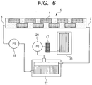
FIG. 6 is a schematic illustration of an exemplary liquid circulation system that can be used for the purpose of the present invention. -
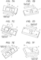
FIGS. 7A, 7B, 7C, 7D, 7E and 7F are schematic views of exemplary introduction ports that can be used for the purpose of the present invention. -
FIGS. 8A, 8B, 8C and 8D are schematic views of other exemplary introduction ports that can also be used for the purpose of the present invention. -
FIGS. 9A and 9B are schematic views of still other exemplary introduction ports that can be used for the purpose of the present invention. -
FIG. 10 is a schematic illustration of the flow of liquid in a liquid chamber. -
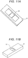
FIGS. 11A and 11B are schematic perspective views of one of the support members of Comparative Example 1. -
FIG. 12 is a graph illustrating the change with time of the highest temperature in the ejection port of the recording element substrate located at the downstream end side of the common flow channel that was observed in Example 1 and also in Comparative Example 1. -
FIG. 13 is a graph illustrating the change with time of the highest temperature in the ejection port of the recording element substrate located at the downstream end side of the common flow channel that was observed in Example 2 and also in Comparative Example 2. - Now, a preferred embodiment of the present invention will be described below by referring to the accompanying drawings. Note, however, that the scope of the present invention is defined only by the appended claims. In other words, the following description of the embodiment by no means limits the scope of the present invention. For example, the shapes, the positional arrangements and so on that are described below do not limit the scope of the present invention by any means. Similarly, while the embodiment that is described below employs recording element substrates that are based on a thermal system, liquid ejection means that are applicable to the present invention are not limited to a thermal system and recording embodiment substrates that are based on a piezo system can also be used for the purpose of the present invention.
-
FIG. 1 is a schematic perspective view of an embodiment of liquid ejection head according to the present invention, which is a line head in which recording element substrates are arranged in a zigzag manner. Theliquid ejection head 5 includes a plurality ofejection members 41 and abase substrate 2. According to this embodiment, anejection member 41 is formed by arecording element substrate 1 and asupport member 4. Thus, therecording element substrates 1 are arranged individually on therespective support members 4. Theejection members 41 are arranged on thebase substrate 2 in a zigzag manner. Note that, in theliquid ejection head 5 of this embodiment, the plurality ofrecording element substrates 1 are arranged in the longitudinal direction of theliquid ejection head 5 and the positions of the recording element substrates are alternatively shifted in the lateral direction of the liquid ejection head such that the recording element substrates are arranged in a zigzag manner as viewed in the longitudinal direction of theliquid ejection head 5. However, therecording element substrates 1 do not necessarily need to be arranged in a zigzag manner. For example, a positional arrangement where recording element substrates having a parallelogrammic or trapezoidal profile are linearly disposed or a positional arrangement where recording element substrates are obliquely disposed at a certain angle relative to the longitudinal direction of thebase substrate 2 may alternatively be adopted. -
FIG. 2A is an exploded schematic perspective view of theliquid ejection head 5 ofFIG. 1 as viewed from the side of therecording element substrates 1 and represents the internal structure of thebase substrate 2.FIG. 2B is an exploded schematic perspective view of the liquid ejection head ofFIG. 1 as viewed from the side of thebase substrate 2.FIG. 3A is a schematic cross sectional view of a part of the liquid ejection head ofFIG. 1 taken along line 3-3 inFIG. 1 . - A
common flow channel 3 through which liquid flows, aninflow port 7 for allowing liquid to flow into thecommon flow channel 3 and anoutflow port 8 for allowing liquid to flow out from thecommon flow channel 3 are formed in thebase substrate 2. Aliquid chamber 6 for storing liquid to be supplied to the liquid supply port 14 (seeFIG. 5 ) of a correspondingrecording element substrate 1 is formed in each of thesupport members 4. Thecommon flow channel 3 communicates with theliquid chamber 6 of each of thesupport members 4 by way of abranch port 31. In each of thebranch ports 31, a first branchport notch portion 51 is formed at the upstream side as viewed in the flow direction of liquid that flows through thecommon flow channel 3, whereas a second branchport notch portion 52, which is separate from the first branchport notch portion 51, is formed at the downstream side. - Each of the
branch ports 31 includes adistribution port 18, which is an opening formed in thebase substrate 2, and anintroduction port 9, which is an opening formed in thecorresponding support member 4 and communicates with thedistribution port 18. In thedistribution port 18, a first distributionport notch portion 53, which operates as part of the first branchport notch portion 51, is formed at the upstream side of the opening thereof as viewed in the flow direction of liquid that flows through the commonliquid path 3, whereas a second distributionport notch portion 54, which operates as part of the second branchport notch portion 52, is formed at the downstream side of the opening thereof. Similarly, in theintroduction port 9, a first introductionport notch portion 55, which operates as part of the first branchport notch portion 51, is formed at the upstream side as viewed in the flow direction of liquid that flows through the commonliquid path 3, whereas a second introductionport notch portion 56, which operates as part of the second branchport notch portion 52, is formed at the downstream side. Each of the notch portions has a part provided with an oblique portion that makes the upstream side profile or the downstream side profile of the opening run neither in parallel with nor perpendicularly relative to the liquid flow direction. - In the instance of
FIGS. 2A and 2B , theintroduction ports 9 and thedistribution ports 18 are so arranged as to be located respectively at the center positions of therespective liquid chambers 6 as viewed in the longitudinal direction of theliquid chambers 6 as illustrated inFIG. 3A . However, theintroduction ports 9 and thedistribution ports 18 may alternatively be arranged at respective positions that are offset toward the upstream side of theliquid chambers 6 as illustrated inFIG. 3B if the desired effects can be obtained by arranging those ports at the upstream side. When the liquid ejection head is filled with ink, bubbles are apt to remain at the upstream side in each of theliquid chambers 6 than at the downstream side. However, the quantity of residual bubbles will be reduced at the upstream side with the arrangement ofFIG. 3B . - With regard to each of the
recording element substrates 1 and thecorresponding support member 4, theliquid chamber 6 and theintroduction port 9 are formed such that the width of theliquid chamber 6 and that of theintroduction port 9 substantially agree with each other in the lateral direction of therecording element substrate 1. While the contour of theintroduction port 9 and that of thedistribution port 18 do not necessarily have to be the same as or similar to each other, at least thenotch portions introduction port 9 and thenotch portions distribution port 18 are respectively located preferably close to each other and more preferably at overlapping positions. - Each of the
recording element substrates 1 is provided with heat generators 13 (seeFIG. 5 ) that are energy generating elements for generating energy to be utilized to eject liquid. This will be described in greater detail hereinafter. Thesupport members 4 have a function of hardly conducting the heat generated in therecording element substrates 1 to thebase substrate 2 and the liquid in thecommon flow channel 3. Therefore, the temperature difference of the liquid in thecommon flow channel 3 is minimized between the upstream end and the downstream end. In other words, the line head is made to represent a subsequently uniform temperature as a whole and hence can record high quality images that are practically free from irregularities. From this point of view, preferably, thesupport members 4 are made of a material representing a low thermal conductivity such as resin and, at the same time, each of theintroduction ports 9 is not made to represent a large opening relative to the contact area of the correspondingliquid chamber 6 and thebase substrate 2. If theintroduction port 9 is made to represent a large opening, the quantity of heat that is conducted from the correspondingrecording element substrate 1 to thecommon flow channel 3 by way of liquid increases. Then, as a result, the temperature difference between therecording element substrates 1 located at the downstream side of thecommon flow channel 3 and therecording element substrates 1 located at the upstream side increases. - When the thermal conductivity in the directions running along the main surface of each
support member 4 can be made low, one ormore support members 4, which or each of which, whichever appropriate, commonly supports a plurality ofrecording element substrates 1 as illustrated inFIG. 2C , may alternatively be employed. In that case, the number of components can be reduced, which is favorable. - The thermal resistance of the
support members 4 between therecording element substrates 1 and thecommon flow channel 3 is preferably not less than 2.5(K/W). With such an arrangement, as therecording element substrates 1 generate heat to a large extent in a high speed high duty image recording operation, the ratio of the quantity of heat that is conducted to the liquid in thecommon flow channel 3 relative to the total quantity of heat that is generated falls. Thus, the quantity of heat that is conducted from therecording element substrates 1 to thebase substrate 2 by way of thesupport members 4 is satisfactorily suppressed when the thermal resistance of thesupport members 4 is made to be not less than 2.5(K/W). Then, most of the heat generated from therecording element substrates 1 is transferred to the liquid in therecording element substrates 1 and dissipated to the outside as liquid is ejected from therecording element substrates 1. With the above-described arrangement, the heat transfer efficiency between therecording element substrates 1 and the liquid ejected from them rises in a high speed high duty image recording operation because the quantity of ejected liquid increases. Therefore, if the quantity of heat generated from therecording element substrates 1 increases, dissipation of heat by way of ejected liquid is accelerated at the same time. The net result will be that the quantity of heat that is transferred from therecording element substrates 1 to thebase substrate 2 remains invariable or decreases. Line heads generally generate heat to a large extent because they include a large number of ejection ports for ejecting liquid. However, with the above-described arrangement, if theliquid ejection head 5 generates heat to a large extent in a high speed high duty operation, the quantity of heat that is transferred to the liquid circulating through thecommon flow channel 3 is suppressed to a low transfer level. Then, since the circulating liquid represents little temperature changes, this arrangement provides advantages that both the temperature control tank and the cooler of the recording apparatus main body are not required to have a large heat exchange capacity and allow a large electric power consumption rate. - If the
recording element substrates 1 and thebase substrate 2 represent a large difference of linear expansibility, thesupport members 4 can come off to give rise to liquid leaking spots when they are heated in the adhesive setting step of the line head manufacturing process particularly when the line head has a long length. Therefore, preferably, thesupport members 4 are made of a material that represents a small thermal conductivity and the difference of linear expansibility from therecording element substrates 1 and thebase substrate 2 is small. Examples of preferable materials to be used for thesupport members 4 include resin materials, particularly low linear expansibility composite materials prepared by using PPS (polyphenyl sulfide) or PSF (polysulfone) as base material and adding an inorganic filler material such as silica fine particles to the base material. - The
base substrate 2 is preferably made of a material representing a relatively low thermal expansion coefficient. Additionally, thebase substrate 2 desirably has a rigidity that does not allow theliquid ejection head 5, which is a line head, to warp and represents a sufficient degree of corrosion resistance against the liquid. A suitable example of such a material is alumina. While thebase substrate 2 may be formed by using a single plate-shaped member, the use of a laminate of a plurality of thin alumina layers is preferable because a three-dimensional fluid path can be formed in the inside of thebase substrate 2 that is made of such a laminate as illustrated inFIG. 2A . - Now, the structure of the
recording element substrates 1 will be described below.FIG. 4 is a schematic perspective view of arecording element substrate 1 andFIG. 5 is a schematic cross sectional view of the recording element substrate taken along line 5-5 inFIG. 4 . In this embodiment, a total of eightejection port rows 17, each having a plurality ofejection ports 11, are formed. While a singleejection port row 17 apparently forms a single opening in the illustration ofFIG. 4 , a plurality ofejection ports 11 are arranged side by side to form a singleejection port row 17 in reality. - The
recording element substrate 1 is based on a thermal system for ink ejection and designed to eject ink by means ofheat generators 13. Therecording element substrates 1 is formed by an ejectionport forming layer 15 and a heater board 16. A plurality ofejection ports 11 and so many foamingchambers 12, which are provided to correspond to therespective ejection ports 11, are arranged in the ejectionport forming layer 15. Longitudinally extendingliquid supply ports 14 for supplying liquid to the foamingchambers 12 andheat generators 13 are formed in the heater board 16. In this embodiment, aliquid supply port 14 is provided for twoejection port rows 17. In other words, a total of fourliquid supply ports 14 are arranged in this embodiment. As described above, theliquid supply ports 14 communicate with theliquid chamber 6 of thecorresponding support members 4. - Electric wiring (not illustrated) is provided in the inside of the heater board 16. The electric wiring is electrically connected to the lead electrode of an FPC (flexible circuit substrate) (not illustrated) arranged on the
base substrate 2 or the electrode (not illustrated) arranged in thebase substrate 2. As a pulse voltage is input to the heater board 16 from the external control circuit (not illustrated) arranged in the recording apparatus main body by way of the electrode, theheat generators 13 are heated to boil the liquid in the foamingchambers 12. Then, liquid droplets are ejected from theejection ports 11. - Sub-heaters 24 and
temperature sensors 25 that are temperature control means are arranged in the inside of the heater board 16 and electrically connected to the FPC and also to the control circuit of the recording apparatus main body. The output signals from thetemperature sensors 25 are transmitted to the control circuit by way of the FPC. When the output values of the temperature sensors are lower than the preset target temperature, the control circuit drives the sub-heaters 24, which are heating means, to heat therecording element substrate 1. As the output values of the temperature sensors rise above the target temperature, the control circuit stops the heating operation of the sub-heaters 24. Since the thermal conductivity of thesupport member 4 of this embodiment is low, the temperature of therecording element substrate 1 easily rises above the target temperature due to the heat that is generated as a result of ejection of liquid in a high duty image recording operation. Then, the heating operation of the sub-heaters 24 is stopped. Meanwhile, since therecording element substrate 1 does not operate to eject liquid during recording standby, the sub-heaters 24 are driven to operate for temperature control. One or more than one sub-heaters 24 may be provided in arecording element substrate 1. If two or more than twosub-heaters 24 are provided, they may be designed to be driven independently or in an interlocked manner for a temperature control operation. With the arrangement illustrated inFIG. 4 , two sub-heaters 24 are formed in arecording element substrate 1 and each of the sub-heaters 24 is driven for a temperature control operation according to the output value of thetemperature sensor 25 that is located at a position closest to the sub-heater 24. With this arrangement, for example, when a half of therecording element substrate 1 is driven for a high duty image recording operation, while the remaining half of therecording element substrate 1 is left inactive and does not eject liquid at all, the liquid non-ejecting region and its vicinity whose temperature becomes relatively low can be locally heated to realize a uniform temperature distribution within therecording embodiment substrate 1. - While an arrangement of providing one or more than one sub-heaters 24 as temperature control means is described above, alternatively,
heat generators 13 arranged in the foamingchambers 12 may be driven to an extent of not causing liquid to be ejected for the purpose of heating therecording element substrate 1. - As illustrated in
FIG. 6 , atemperature control tank 22, acirculation pump 19, afeed pump 20, afilter 21, aliquid tank 23 and so on are provided in a recording apparatus that includes aliquid ejection head 5 according to the present invention. In theliquid ejection head 5, theinflow port 7 for supplying liquid to thecommon flow channel 3 is linked to a tube that communicates with thetemperature control tank 22, while theoutflow port 8 for flowing liquid out of thecommon flow channel 3 is linked to another tube that communicates with thecirculation pump 19. - As the
liquid ejection head 5 is driven, thecirculation pump 19 is put into operation to circulate the liquid in thecommon flow channel 3. Thetemperature control tank 22 is linked to a heat exchanger (not illustrated) so that it can be subjected to heat exchange operations. Thetemperature control tank 22 has a function of supplying liquid to theliquid ejection head 5 and at the same time maintaining the temperature of the liquid that circulates through thecirculation pump 19 to a constant temperature level. Additionally, thetemperature control tank 22 is provided with a hole (not illustrated) for communicating with the open air. In other words, thetemperature control tank 22 additionally has a function of expelling bubbles in the liquid in the tank to the outside. The temperature of the liquid flowing out from theoutflow port 8 is controlled and regulated by thetemperature control tank 22 before the liquid is directed toward theinflow port 7 and hence the temperature of the liquid located at the position of theinflow port 7 can always be held within a certain temperature range. When the temperature of therecording element substrates 1 is too high, the target temperature for the temperature control operation of thetemperature control tank 22 may be lowered so as to supply liquid to theliquid ejection head 5 at a relatively low temperature. - The
feed pump 20 can transfer liquid from theliquid tank 23 that stores liquid to thetemperature control tank 22 after removing the foreign objects contained in the liquid by means of thefilter 21 so as to supply liquid to thetemperature control tank 22 for the liquid consumed by theliquid ejection head 5 as a result of an image recording operation. - Now, the arrangement of providing the
branch port 31 with the first and second branchport notch portions FIGS. 7A through 7F ,8A through 8D ,9A and 9B . Note that thesupport member 4 having theintroduction port 9, which thebranch port 31 includes, will be described first for the purpose of easy understanding of the profile of thebranch port 31. Also note that thedistribution port 18 will not be described below because it has a profile substantially the same as the profile of theintroduction port 9. -
FIGS. 7A through 7F and8A through 8D are schematic illustrations of exemplary profiles that theintroduction port 9 can selectively take.FIGS. 7A, 7C, 7E ,8A and 8C are schematic perspective views ofsupport member 4, illustrating the exemplary profiles thereof as viewed from the side of therecording element substrate 1.FIGS. 7B, 7D, 7F ,8B and 8D are schematic perspective views ofsupport member 4, illustrating the exemplary profiles illustrated inFIGS. 7A, 7C, 7E ,8A and 8C as viewed from the side of thebase substrate 2.FIGS. 9A and 9B are schematic views ofintroduction port 9, illustrating other exemplary profiles thereof. More specifically,FIG. 9A is a schematic perspective view ofsupport member 4 as viewed from the side of thebase substrate 2 andFIG. 9B is a schematic perspective view ofsupport member 4 as viewed from therecording element substrate 1. Note thatFIG. 9B represents the internal structure of thesupport member 4 by broken lines. -
FIG. 7A through 7F ,8A and 8B illustrates arrangements where a singleliquid chamber 6 is formed in asingle support member 4, whereasFIGS. 8C, 8D and9A illustrates arrangements where two liquid chambers are formed in asingle support member 4.FIG. 9B illustrates an arrangement where a total of fourliquid chambers 4 are formed in asingle support member 4. - Arrangements of forming a plurality of liquid chambers in a
single support member 4 provide an advantage that therecording element substrate 1 and thesupport member 4 can have a large contact area to ensure a high degree of adhesion between therecording element substrate 1 and thesupport member 4 and minimize the risk of liquid leakage through the interface. On the other hand, the arrangements are accompanied by a disadvantage that each of theliquid chambers 6 inevitably has a small size and hence bubbles can remain in theliquid chambers 6 when they are filled with liquid. In other words, no problem arises if two or more than two liquid chambers are formed in asingle support member 4 provided that there is no risk of remaining bubbles.FIG. 9B illustrates an arrangement of forming fourliquid chambers 6 in asingle support member 4. Such an arrangement can also be adopted for the purpose of the present invention. - In the
support member 4 whose exemplary profiles are illustrated inFIGS. 7A through 7F ,8A through 8D and9A , theliquid chambers 6 represent a rectangular cross section as viewed in the longitudinal direction and have a shape of a rectangular parallelepiped. However, theliquid chambers 6 do not necessarily have a shape of a rectangular parallelepiped. In other words, theliquid chambers 6 may alternatively represent a substantially triangular cross section as illustrated inFIG. 9B or a trapezoidal cross section as viewed in the longitudinal direction. - According to the present invention, each of the
branch ports 31 is provided with the first and second branchport notch portions 51 and 52 (seeFIGS. 2A through 2C ) in order to make thebranch port 31 have a function of producing swirling currents in theliquid chamber 6 to effectively stir the liquid in theliquid chamber 6, by exploiting the power of the liquid flowing through thecommon flow channel 3 as drive force in a recording standby status where a temperature control operation is conducted. This function can suppress the unevenness of temperature distribution, if any, in the liquid in theliquid chamber 6. - Firstly, the first and second branch
port notch portions port notch portions - As illustrated in
FIGS. 7A through 7F ,8A through 8D ,9A and 9B , there are a variety of different profiles that can selectively be employed for the first and second introductionport notch portions port notch portions introduction port 9 as viewed from the liquid flowing through thecommon flow channel 3 so as to be asymmetric relative to the center line of thecommon flow channel 3 running along the flow direction of liquid. More specifically, the opening of theintroduction port 9 at least at the upstream side represents a profile that is asymmetric relative to the straight line that passes through the center of gravity of the opening and runs along the flow of liquid. Preferably, the first and second introductionport notch portions introduction port 9 as viewed in the direction perpendicular to the flow direction of liquid running through thecommon flow channel 3. - As illustrated in
FIGS. 8A and 8B , theintroduction port 9 may not necessarily be provided with the second introductionport notch portion 56. However, from the viewpoint of the advantages of the present invention, theintroduction port 9 may preferably be provided with the second introductionport notch portion 56 as illustrated inFIGS. 7A through 7F ,8C ,8D ,9A and 9B . The first and second introductionport notch portions - For the purpose of the present invention, "notch portions" may be produced by partly notching (forming a cutout portion at) the
introduction port 9 at the upstream side and at the downstream side as viewed in the flow direction of liquid flowing through thecommon flow channel 3. Alternatively, "notch portions" may be produced by making theintroduction port 9 wholly inclined both at the upstream side and at the downstream side as viewed in the flow direction of liquid flowing through thecommon flow channel 3. - Preferably, the first introduction
port notch portion 55 has a part which is an extension of thelateral wall 6a of theliquid chamber 6 because, with such an arrangement, theliquid chamber 6 can be filled with liquid without any residual bubbles. This is because, when the liquid introduced into theliquid chamber 6 from thecommon flow channel 3 gets to theintroduction port 9, the first introductionport notch portion 55 forms a liquid flow path that guides the liquid to thelateral wall 6a of theliquid chamber 6 and makes the liquid reach the bottom of theliquid chamber 6. Once such a liquid flow path is established, liquid will preferentially flow through the established flow path so that theliquid chamber 6 will be filled with liquid from the bottom thereof. Then, a situation where theintroduction port 9 is blocked by liquid to leave residual bubbles in theliquid chamber 6 will effectively be prevented from taking place. Similarly, the second introductionport notch portion 56 also preferably has a part which is an extension of thelateral wall 6a of theliquid chamber 6. With such an arrangement, when liquid flows out from theliquid chamber 6 into thecommon flow channel 3, the fluid can flow from the secondintroduction notch portion 56 into thecommon flow channel 3 along thelateral wall 6a of theliquid chamber 6. - As for the positional relationship between the first introduction
port notch portion 55 and the second introductionport notch portion 56, they may be arranged at the same position on the upstream and downstream sides respectively as viewed in a direction orthogonal relative to the flow direction of liquid flowing through thecommon flow channel 3 as illustrated inFIGS. 7E, 7F ,8C, 8D ,9A and 9B . Alternatively, the first and second introductionport notch portions common flow channel 3. The latter arrangement is preferable because the effects and the advantages of the present invention, which will be described below, can be maximized. - Now, the effects of the first branch
port notch portion 51 and the second branchport notch portion 52 will be described in detail by referring toFIG. 10 . Like the preceding description, the effects will be described by way of thesupport member 4 having theintroduction port 9.FIG. 10 is a schematic illustration of the flow of liquid in theliquid chamber 6, which can be observed when thesupport member 4 ofFIGS. 7C and 7D is employed. Note thatFIG. 10 illustrates thesupport member 4 as viewed from the side of thebase substrate 2 and that theliquid chamber 6 in the inside of thesupport member 4 is indicated by broken lines for the purpose of the flow of liquid being easily recognized. Also note that the arrow inFIG. 10 indicates the flow of liquid in a recording standby status where a temperature control operation is conducted. - As illustrated in
FIG. 10 , part of the liquid that flows through thecommon flow channel 3 and gets to the first introductionport notch portion 55 forms a flow that intrudes into theliquid chamber 6 from the first introduction port notch portion 55 (intruding flow). The intruding flow actually forms liquid flow (the first flow) A that runs along thelateral wall 6a of theliquid chamber 6 toward the bottom of the liquid chamber 6 (and hence the part thereof located at the side of the recording element substrate 1) due to capillary force and gravitation so as to collide with the bottom and then is directed toward the upstream side in terms of the liquid flow flowing through thecommon flow channel 3 at and near the bottom of theliquid chamber 6. - On the other hand, liquid flow (the second flow) B is formed so as to be directed from the
liquid chamber 6 to thecommon flow channel 3 by way of the secondintroduction notch portion 56 at and near the second introductionport notch portion 56 that is formed at the downstream side of the introduction port. Swirling currents as illustrated inFIG. 10 are produced in theliquid chamber 6 due to the effects of the first flow A and the second flow B. - Generally, the liquid in the liquid chamber is heated by the sub-heaters of the recording element substrate in a recording standby status during a temperature control operation so that a high temperature region is formed in the liquid in the liquid chamber. On the other hand, with the arrangement of the present invention, the liquid in the
common flow channel 3 is forced to circulate when no liquid is ejected from the liquid ejection head and hence the liquid in theliquid chamber 6 is stirred by swirling currents as described above so that a high temperature region can hardly be formed in the liquid in theliquid chamber 6. Therefore, the temperature of the liquid that is supplied to therecording element substrate 1 can be held low at the time of starting an image recording operation. In other words, due to the effect of the first and second branchport notch portions liquid chamber 6 by utilizing the liquid flowing through thecommon flow channel 3 to promote the effect of stirring the liquid in theliquid chamber 6 and reduce the temperature difference in the liquid in a recording standby status during a temperature control operation. - When the
liquid chamber 6 has a relatively large size, the liquid in theliquid chamber 6 is stirred by natural convection in theliquid chamber 6 to provide a stirring effect similar to that of the present invention. If such is the case, however, the liquid stirring effect in theliquid chamber 6 can be intensified by employing the above-described arrangement of the present invention to prevent a high temperature region from being produced in the liquid in theliquid chamber 6. - The advantages of the present invention were verified by way of numerical analysis simulations.
- In Example 1, a liquid ejection head 5 (line head) as illustrated in
FIG. 1 that was configured by employingsupport members 4 having a structure as illustrated inFIGS. 7A and 7B was connected to atemperature control tank 22, acirculation pump 19 and so on as illustrated inFIG. 6 and held in a recording standby status, while driving the liquid ejection head to operate and control the temperature of the liquid in theliquid ejection head 5. - In Comparative Example 1, a liquid ejection head which is the same as that of Example 1 except that
support members 61, each having anintroduction port 62 that was not provided with notch portions as illustrated inFIGS. 11A and 11B were employed was prepared and subjected to a numerical analysis simulation. Note thatFIG. 11A is a schematic perspective view of asupport member 61 as viewed from the side of the recording element substrate andFIG. 11B is a schematic perspective view of thesupport member 61 as viewed from the side of the base substrate. - Both in Example 1 and Comparative Example 1, the distribution ports and the introduction ports were made to represent the same profiles. More specifically, although not illustrated, first and second distribution
port notch portions distribution port 18 of thebase substrate 2. To reduce the temperature differences among the recording element substrates, in each of the support members, the opening area of the introduction port is made to be equal to 25% of the contact area of the support member and the base substrate to suppress the quantity of heat that is conducted from each of the recording element substrates to the base substrate. - For the simulations, the rate at which liquid is circulated through the common flow channel was made to be equal to 25 mL/min and the temperature of each of the recording element substrates was so controlled as to be made equal to 55°C. Other conditions used for the calculations in the numerical analyses include supplied electric power per recording element substrate: 22.5(W), recording speed: 18 (inch/s), ejected liquid droplet size: 2.8 (pL), image resolution: 1,200 (dpi) and supplied liquid temperature: 27 (°C).
- In Example 1, the average liquid volume at not lower than 40°C in each of the
liquid chambers 6 in a recording standby status during a temperature control operation was 0.39 mL. In Comparative Example 1, on the other hand, the average liquid volume at not lower than 40°C in each of theliquid chambers 6 in a recording standby status during a temperature control operation was 0.41 mL. The average liquid volume in each of theliquid chambers 6 at not lower than 40°C was smaller in Example 1 than in Comparative Example 1. It may be safe to say that this was because the liquid in each of the liquid chambers of Example 1 was stirred due to the operational effect of the notch portions. - In each of the liquid ejection heads of Example 1 and Comparative Example 1, the recording element substrates were held in a recording standby status for 30 seconds during a temperature control operation and subsequently the liquid ejection head was driven to record a 100% solid image.
FIG. 12 illustrates the change with time of the highest temperature in the ejection port of the recording element substrate located at the most downstream side of thecommon flow channel 3 in Example 1 and Comparative Example 1. As seen fromFIG. 12 , the highest temperature in the ejection port was lower in Example 1 than in Comparative Example 1 after the start of the image recording operation. - In Example 2, a liquid ejection head 5 (line head) which is the same as that of Example 1 was prepared except that
support members 4, each having four liquid chambers as illustrated inFIG. 9B , were employed to form theliquid ejection head 5. In Comparative Example 2, aliquid ejection head 5 which is the same as that of Example 2 was prepared except that no notch portion was provided. Both theliquid ejection head 5 of Example 2 and that of Comparative Example 2 were subjected to a numerical analysis simulation. The conditions used for the calculations in the numerical analyses were the same as those of Example 1, which are described above. - In each of Example 2 and Comparative Example 2, the recording element substrates were held in a recording standby status for 300 seconds during a temperature control operation and subsequently the liquid ejection head was driven to record a 100% solid image.
FIG. 13 illustrates the change with time of the highest temperature in the ejection port of the recording element substrate located at the most downstream side of thecommon flow channel 3 in Example 2 and Comparative Example 2. As seen fromFIG. 13 , the highest temperature in the ejection port was lower in Example 2 than in Comparative Example 2 after the start of the image recording operation. - As seen from the above description, a liquid ejection head according to the present invention suppresses the temperature rise of each of the recording element substrates after the start of an image recording operation when a temperature control operation is conducted for each of the
recording element substrates 1 while it is held in a recording standby status. The net result is that the liquid ejection head can reliably operate for high speed image recording without image irregularities. - While the present invention has been described with reference to exemplary embodiments, it is to be understood that the invention is not limited to the disclosed exemplary embodiments.
Claims (14)
- A liquid ejection head (5) comprising:a plurality of ejection members (41), each having an ejection port (11) for ejecting liquid, an energy generating element for generating energy to be utilized to eject liquid from the ejection port (13), a liquid chamber (6) for storing liquid to be supplied to the ejection port and a heater (24);a base substrate (2) bearing, on a surface thereof, the plurality of ejection members; anda common flow channel (3) formed in the base substrate and running along said surface, for supplying liquid to the plurality of liquid chambers;wherein the common flow channel communicates with the liquid chambers by way of respective branch ports (31) directly connecting, in a direction perpendicular to said surface of the base substrate, the common flow channel and a respective liquid chamber, and,as viewed in the direction perpendicular to said surface of the base substrate, each of the branch ports has a profile with an oblique portion at an upstream side with respect to a flow direction of liquid flowing through the common flow channel, said oblique portion being provided by a first notch portion (51).
- The liquid ejection head (5) according to claim 1, wherein,
as viewed in the direction perpendicular to said surface of the base substrate, the first notch portion (51) of each of the branch ports (31) is arranged at at least an end of the upstream side of the branch port with respect to a direction orthogonal relative to the flow direction of liquid flowing through the common flow channel (3). - The liquid ejection head (5) according to claims 1 or 2, wherein,
as viewed in the direction perpendicular to said surface of the base substrate, a second notch portion (52) is formed at a downstream side of each of the branch ports (31) with respect to the flow direction of liquid flowing through the common flow channel (3) such that the respective branch port has a profile with an oblique portion also at said downstream side. - The liquid ejection head (5) according to claim 3, wherein,
as viewed in the direction perpendicular to said surface of the base substrate, the first notch portion (51) and the second notch portion (52) of each of the branch ports are arranged at respective ends of the upstream and downstream sides of the branch port (31) with respect to the direction orthogonal relative to the flow direction of liquid flowing through the common flow channel (3). - The liquid ejection head (5) according to claims 3 or 4, wherein,
as viewed in the direction perpendicular to said surface of the base substrate, the first notch portion (51) and the second notch portion (52) of each of the branch ports (31) are arranged at the same position on the upstream and downstream sides respectively of the branch port with respect to the direction orthogonal relative to the flow direction of liquid flowing through the common flow channel (3). - The liquid ejection head (5) according to claims 3 or 4, wherein,
as viewed in the direction perpendicular to said surface of the base substrate, the first notch portion (51) and the second notch portion (52) of each of the branch ports (31) are arranged at different positions on the upstream and downstream sides respectively of the branch port with respect to the direction orthogonal relative to the flow direction of liquid flowing through the common flow channel (3). - The liquid ejection head (5) according to any one of claims 3 to 6, wherein,
as viewed in the direction perpendicular to said surface of the base substrate, the first notch portion (51) and the second notch portion (52) of each of the branch ports (31) have profiles shaped by notching the upstream and downstream sides respectively of the branch port. - The liquid ejection head (5) according to any one of claims 3 to 6, wherein,
as viewed in the direction perpendicular to said surface of the base substrate, the first notch portion (51) and the second notch portion (52) of each of the branch ports (31) have profiles shaped by inclining all the upstream and downstream sides respectively of the branch port from the direction orthogonal relative to the flow direction of liquid flowing through the common flow channel (3). - The liquid ejection head (5) according to any one of claims 3 to 8, wherein,
as viewed in the direction perpendicular to said surface of the base substrate, the first notch portion (51) and the second notch portion (52) of each of the branch ports (31) have respective parts which coincide with a lateral wall of the liquid chamber (6). - The liquid ejection head (5) according to any one of claims 1 to 9, wherein
each of the branch ports (51) is produced as an introduction port (9) formed at the ejection member (41) so as to communicate with the liquid chamber (6) and supply liquid to the ejection port (11) and a distribution port (18) formed at the base substrate (2) so as to communicate with the common flow channel (3) which are made to communicate with each other. - The liquid ejection head (5) according to any one of claims 1 to 10, whereineach of the ejection members (41) has a recording element substrate (1) and a support member (4),the ejection port (11) of the ejection member is formed at the recording element substrate while the liquid chamber (6) of the ejection member is formed in the support member,the recording element substrate is provided with a liquid supply port (14) for supplying liquid from the liquid chamber to the ejection port, andthe thermal resistance of the support member is not less than 2.5 K/W.
- The liquid ejection head (5) according to any one of claims 1 to 10, whereineach of the ejection members (41) has a recording element substrate (1) in which the ejection port (11) of the ejection member is formed,the recording element substrates of the plurality of ejection members are supported by a common support member (4) in which the liquid chamber (6) of each ejection member is formed,each recording element substrate is provided with a liquid supply port (14) for supplying liquid from the respective liquid chamber to the respective ejection,and wherein the thermal resistance of the support member is not less than 2.5 K/W.
- The liquid ejection head (5) according to any one of claims 1 to 12, wherein,
as viewed in the direction perpendicular to said surface of the base substrate, each of the branch ports (31) has a profile asymmetric with regard to a center line of the branch port along the flow direction of liquid flowing through the common flow channel (3). - The liquid ejection head (5) according to any one of claims 1 to 13, wherein,
as viewed in the direction perpendicular to said surface of the base substrate, the plurality of ejection members (41) are arranged along the common flow channel (3).
Applications Claiming Priority (1)
| Application Number | Priority Date | Filing Date | Title |
|---|---|---|---|
| JP2013196837 | 2013-09-24 |
Publications (2)
| Publication Number | Publication Date |
|---|---|
| EP2853398A1 EP2853398A1 (en) | 2015-04-01 |
| EP2853398B1 true EP2853398B1 (en) | 2019-11-06 |
Family
ID=51582230
Family Applications (1)
| Application Number | Title | Priority Date | Filing Date |
|---|---|---|---|
| EP14003238.4A Active EP2853398B1 (en) | 2013-09-24 | 2014-09-18 | Liquid ejection head |
Country Status (6)
| Country | Link |
|---|---|
| US (1) | US9452606B2 (en) |
| EP (1) | EP2853398B1 (en) |
| JP (1) | JP6463034B2 (en) |
| KR (1) | KR101779247B1 (en) |
| CN (1) | CN104441981B (en) |
| RU (1) | RU2604445C2 (en) |
Families Citing this family (11)
| Publication number | Priority date | Publication date | Assignee | Title |
|---|---|---|---|---|
| JP6270533B2 (en) | 2014-02-25 | 2018-01-31 | キヤノン株式会社 | Liquid ejection head, recording apparatus, and heat dissipation method for liquid ejection head |
| JP6957147B2 (en) * | 2016-01-08 | 2021-11-02 | キヤノン株式会社 | Liquid discharge head and liquid discharge device |
| JP6961379B2 (en) * | 2016-05-27 | 2021-11-05 | キヤノン株式会社 | Liquid discharge device |
| JP6859043B2 (en) * | 2016-07-22 | 2021-04-14 | キヤノン株式会社 | Liquid discharge head |
| JP6987543B2 (en) * | 2017-06-20 | 2022-01-05 | キヤノン株式会社 | Substrate for liquid discharge head |
| JP6968592B2 (en) * | 2017-06-28 | 2021-11-17 | キヤノン株式会社 | Liquid discharge head |
| JP7057071B2 (en) | 2017-06-29 | 2022-04-19 | キヤノン株式会社 | Liquid discharge module |
| JP7019318B2 (en) | 2017-06-29 | 2022-02-15 | キヤノン株式会社 | Liquid discharge head and liquid discharge device |
| JP6961404B2 (en) | 2017-06-29 | 2021-11-05 | キヤノン株式会社 | Liquid discharge head and liquid discharge device |
| JP6949586B2 (en) | 2017-06-30 | 2021-10-13 | キヤノン株式会社 | Manufacturing method of liquid discharge head, liquid discharge device and liquid discharge head |
| JP7039231B2 (en) | 2017-09-28 | 2022-03-22 | キヤノン株式会社 | Liquid discharge head and liquid discharge device |
Family Cites Families (19)
| Publication number | Priority date | Publication date | Assignee | Title |
|---|---|---|---|---|
| JP2976479B2 (en) | 1990-04-17 | 1999-11-10 | セイコーエプソン株式会社 | Inkjet head |
| US6081280A (en) * | 1996-07-11 | 2000-06-27 | Lexmark International, Inc. | Method and apparatus for inhibiting electrically induced ink build-up on flexible, integrated circuit connecting leads, for thermal ink jet printer heads |
| US6449831B1 (en) * | 1998-06-19 | 2002-09-17 | Lexmark International, Inc | Process for making a heater chip module |
| US6328423B1 (en) * | 1999-08-16 | 2001-12-11 | Hewlett-Packard Company | Ink jet cartridge with integrated circuitry |
| KR100408268B1 (en) * | 2000-07-20 | 2003-12-01 | 삼성전자주식회사 | Bubble-jet type ink-jet printhead and manufacturing method thereof |
| US6979077B2 (en) | 2002-02-20 | 2005-12-27 | Brother Kogyo Kabushiki Kaisha | Ink-jet head and ink-jet printer having ink-jet head |
| JP2004314396A (en) * | 2003-04-15 | 2004-11-11 | Seiko Epson Corp | Ink jet head |
| TWI246115B (en) | 2004-01-16 | 2005-12-21 | Benq Corp | Method for fabricating an enlarged fluid chamber using multiple sacrificial layers |
| JP4019199B2 (en) * | 2004-09-06 | 2007-12-12 | 富士フイルム株式会社 | Liquid discharge head and liquid discharge apparatus |
| JP4729957B2 (en) | 2005-03-24 | 2011-07-20 | 富士ゼロックス株式会社 | Droplet discharge head bar, droplet discharge apparatus, and droplet discharge head bar manufacturing method |
| JP5046841B2 (en) * | 2007-10-03 | 2012-10-10 | キヤノン株式会社 | Inkjet recording head |
| JP2009149055A (en) * | 2007-11-30 | 2009-07-09 | Canon Inc | Inkjet recording head and inkjet recording apparatus |
| JP2009255448A (en) * | 2008-04-18 | 2009-11-05 | Canon Inc | Inkjet recording head |
| CN103552379B (en) | 2008-05-22 | 2015-09-02 | 富士胶片株式会社 | Fluid ejection apparatus |
| US7988260B2 (en) * | 2008-11-20 | 2011-08-02 | Canon Kabushiki Kaisha | Recording element substrate and recording head including recording element substrate |
| JP5404331B2 (en) | 2008-12-17 | 2014-01-29 | キヤノン株式会社 | Ink jet recording head, recording element substrate, method for manufacturing ink jet recording head, and method for manufacturing recording element substrate |
| US8157352B2 (en) | 2009-02-26 | 2012-04-17 | Fujifilm Corporation | Fluid ejecting with centrally formed inlets and outlets |
| JP5656451B2 (en) | 2010-05-14 | 2015-01-21 | キヤノン株式会社 | Liquid ejection head and electric wiring board |
| JP6381355B2 (en) * | 2013-09-24 | 2018-08-29 | キヤノン株式会社 | Liquid discharge head |
-
2014
- 2014-08-11 JP JP2014163552A patent/JP6463034B2/en active Active
- 2014-09-04 US US14/477,013 patent/US9452606B2/en not_active Expired - Fee Related
- 2014-09-16 KR KR1020140122769A patent/KR101779247B1/en active IP Right Grant
- 2014-09-18 EP EP14003238.4A patent/EP2853398B1/en active Active
- 2014-09-23 RU RU2014138416/12A patent/RU2604445C2/en active
- 2014-09-24 CN CN201410495493.0A patent/CN104441981B/en active Active
Non-Patent Citations (1)
| Title |
|---|
| None * |
Also Published As
| Publication number | Publication date |
|---|---|
| RU2604445C2 (en) | 2016-12-10 |
| JP2015085677A (en) | 2015-05-07 |
| JP6463034B2 (en) | 2019-01-30 |
| EP2853398A1 (en) | 2015-04-01 |
| RU2014138416A (en) | 2016-04-10 |
| US9452606B2 (en) | 2016-09-27 |
| KR101779247B1 (en) | 2017-09-18 |
| KR20150033542A (en) | 2015-04-01 |
| CN104441981B (en) | 2017-06-09 |
| US20150085017A1 (en) | 2015-03-26 |
| CN104441981A (en) | 2015-03-25 |
Similar Documents
| Publication | Publication Date | Title |
|---|---|---|
| EP2853398B1 (en) | Liquid ejection head | |
| EP2853397B1 (en) | Liquid ejection head | |
| KR102383356B1 (en) | Liquid ejection head and liquid ejection apparatus | |
| US9254658B2 (en) | Liquid ejection head and liquid ejection apparatus | |
| US9162453B2 (en) | Printhead including integrated circuit die cooling | |
| JP6253460B2 (en) | Liquid ejecting head and liquid ejecting apparatus | |
| JP6044763B2 (en) | Liquid ejecting head and liquid ejecting apparatus | |
| JP2017144719A (en) | Liquid discharge head and liquid discharge device | |
| JP5843720B2 (en) | Inkjet recording head | |
| JP2018518386A (en) | Fluid recirculation channel | |
| CN111645422B (en) | Liquid discharge head and liquid discharge apparatus | |
| US8789912B2 (en) | Inkjet recording head | |
| US9815287B2 (en) | Liquid discharge head and liquid discharge apparatus | |
| US8845081B2 (en) | Liquid discharge head | |
| EP3771566B1 (en) | Liquid ejecting head and liquid ejecting apparatus | |
| JP7255238B2 (en) | Liquid ejection head and liquid ejection device | |
| US11312135B2 (en) | Liquid ejecting head | |
| JP2014136401A (en) | Recording head |
Legal Events
| Date | Code | Title | Description |
|---|---|---|---|
| PUAI | Public reference made under article 153(3) epc to a published international application that has entered the european phase |
Free format text: ORIGINAL CODE: 0009012 |
|
| 17P | Request for examination filed |
Effective date: 20140918 |
|
| AK | Designated contracting states |
Kind code of ref document: A1 Designated state(s): AL AT BE BG CH CY CZ DE DK EE ES FI FR GB GR HR HU IE IS IT LI LT LU LV MC MK MT NL NO PL PT RO RS SE SI SK SM TR |
|
| AX | Request for extension of the european patent |
Extension state: BA ME |
|
| R17P | Request for examination filed (corrected) |
Effective date: 20151001 |
|
| RBV | Designated contracting states (corrected) |
Designated state(s): AL AT BE BG CH CY CZ DE DK EE ES FI FR GB GR HR HU IE IS IT LI LT LU LV MC MK MT NL NO PL PT RO RS SE SI SK SM TR |
|
| STAA | Information on the status of an ep patent application or granted ep patent |
Free format text: STATUS: EXAMINATION IS IN PROGRESS |
|
| 17Q | First examination report despatched |
Effective date: 20181008 |
|
| GRAP | Despatch of communication of intention to grant a patent |
Free format text: ORIGINAL CODE: EPIDOSNIGR1 |
|
| STAA | Information on the status of an ep patent application or granted ep patent |
Free format text: STATUS: GRANT OF PATENT IS INTENDED |
|
| INTG | Intention to grant announced |
Effective date: 20190524 |
|
| GRAS | Grant fee paid |
Free format text: ORIGINAL CODE: EPIDOSNIGR3 |
|
| RAP1 | Party data changed (applicant data changed or rights of an application transferred) |
Owner name: CANON KABUSHIKI KAISHA |
|
| GRAA | (expected) grant |
Free format text: ORIGINAL CODE: 0009210 |
|
| STAA | Information on the status of an ep patent application or granted ep patent |
Free format text: STATUS: THE PATENT HAS BEEN GRANTED |
|
| AK | Designated contracting states |
Kind code of ref document: B1 Designated state(s): AL AT BE BG CH CY CZ DE DK EE ES FI FR GB GR HR HU IE IS IT LI LT LU LV MC MK MT NL NO PL PT RO RS SE SI SK SM TR |
|
| REG | Reference to a national code |
Ref country code: GB Ref legal event code: FG4D |
|
| REG | Reference to a national code |
Ref country code: CH Ref legal event code: EP Ref country code: AT Ref legal event code: REF Ref document number: 1198206 Country of ref document: AT Kind code of ref document: T Effective date: 20191115 |
|
| REG | Reference to a national code |
Ref country code: IE Ref legal event code: FG4D |
|
| REG | Reference to a national code |
Ref country code: DE Ref legal event code: R096 Ref document number: 602014056154 Country of ref document: DE |
|
| REG | Reference to a national code |
Ref country code: NL Ref legal event code: MP Effective date: 20191106 |
|
| REG | Reference to a national code |
Ref country code: LT Ref legal event code: MG4D |
|
| PG25 | Lapsed in a contracting state [announced via postgrant information from national office to epo] |
Ref country code: LV Free format text: LAPSE BECAUSE OF FAILURE TO SUBMIT A TRANSLATION OF THE DESCRIPTION OR TO PAY THE FEE WITHIN THE PRESCRIBED TIME-LIMIT Effective date: 20191106 Ref country code: SE Free format text: LAPSE BECAUSE OF FAILURE TO SUBMIT A TRANSLATION OF THE DESCRIPTION OR TO PAY THE FEE WITHIN THE PRESCRIBED TIME-LIMIT Effective date: 20191106 Ref country code: NL Free format text: LAPSE BECAUSE OF FAILURE TO SUBMIT A TRANSLATION OF THE DESCRIPTION OR TO PAY THE FEE WITHIN THE PRESCRIBED TIME-LIMIT Effective date: 20191106 Ref country code: ES Free format text: LAPSE BECAUSE OF FAILURE TO SUBMIT A TRANSLATION OF THE DESCRIPTION OR TO PAY THE FEE WITHIN THE PRESCRIBED TIME-LIMIT Effective date: 20191106 Ref country code: FI Free format text: LAPSE BECAUSE OF FAILURE TO SUBMIT A TRANSLATION OF THE DESCRIPTION OR TO PAY THE FEE WITHIN THE PRESCRIBED TIME-LIMIT Effective date: 20191106 Ref country code: LT Free format text: LAPSE BECAUSE OF FAILURE TO SUBMIT A TRANSLATION OF THE DESCRIPTION OR TO PAY THE FEE WITHIN THE PRESCRIBED TIME-LIMIT Effective date: 20191106 Ref country code: BG Free format text: LAPSE BECAUSE OF FAILURE TO SUBMIT A TRANSLATION OF THE DESCRIPTION OR TO PAY THE FEE WITHIN THE PRESCRIBED TIME-LIMIT Effective date: 20200206 Ref country code: PL Free format text: LAPSE BECAUSE OF FAILURE TO SUBMIT A TRANSLATION OF THE DESCRIPTION OR TO PAY THE FEE WITHIN THE PRESCRIBED TIME-LIMIT Effective date: 20191106 Ref country code: NO Free format text: LAPSE BECAUSE OF FAILURE TO SUBMIT A TRANSLATION OF THE DESCRIPTION OR TO PAY THE FEE WITHIN THE PRESCRIBED TIME-LIMIT Effective date: 20200206 Ref country code: GR Free format text: LAPSE BECAUSE OF FAILURE TO SUBMIT A TRANSLATION OF THE DESCRIPTION OR TO PAY THE FEE WITHIN THE PRESCRIBED TIME-LIMIT Effective date: 20200207 Ref country code: PT Free format text: LAPSE BECAUSE OF FAILURE TO SUBMIT A TRANSLATION OF THE DESCRIPTION OR TO PAY THE FEE WITHIN THE PRESCRIBED TIME-LIMIT Effective date: 20200306 |
|
| PG25 | Lapsed in a contracting state [announced via postgrant information from national office to epo] |
Ref country code: RS Free format text: LAPSE BECAUSE OF FAILURE TO SUBMIT A TRANSLATION OF THE DESCRIPTION OR TO PAY THE FEE WITHIN THE PRESCRIBED TIME-LIMIT Effective date: 20191106 Ref country code: HR Free format text: LAPSE BECAUSE OF FAILURE TO SUBMIT A TRANSLATION OF THE DESCRIPTION OR TO PAY THE FEE WITHIN THE PRESCRIBED TIME-LIMIT Effective date: 20191106 Ref country code: IS Free format text: LAPSE BECAUSE OF FAILURE TO SUBMIT A TRANSLATION OF THE DESCRIPTION OR TO PAY THE FEE WITHIN THE PRESCRIBED TIME-LIMIT Effective date: 20200306 |
|
| PG25 | Lapsed in a contracting state [announced via postgrant information from national office to epo] |
Ref country code: AL Free format text: LAPSE BECAUSE OF FAILURE TO SUBMIT A TRANSLATION OF THE DESCRIPTION OR TO PAY THE FEE WITHIN THE PRESCRIBED TIME-LIMIT Effective date: 20191106 |
|
| PG25 | Lapsed in a contracting state [announced via postgrant information from national office to epo] |
Ref country code: CZ Free format text: LAPSE BECAUSE OF FAILURE TO SUBMIT A TRANSLATION OF THE DESCRIPTION OR TO PAY THE FEE WITHIN THE PRESCRIBED TIME-LIMIT Effective date: 20191106 Ref country code: RO Free format text: LAPSE BECAUSE OF FAILURE TO SUBMIT A TRANSLATION OF THE DESCRIPTION OR TO PAY THE FEE WITHIN THE PRESCRIBED TIME-LIMIT Effective date: 20191106 Ref country code: EE Free format text: LAPSE BECAUSE OF FAILURE TO SUBMIT A TRANSLATION OF THE DESCRIPTION OR TO PAY THE FEE WITHIN THE PRESCRIBED TIME-LIMIT Effective date: 20191106 Ref country code: DK Free format text: LAPSE BECAUSE OF FAILURE TO SUBMIT A TRANSLATION OF THE DESCRIPTION OR TO PAY THE FEE WITHIN THE PRESCRIBED TIME-LIMIT Effective date: 20191106 |
|
| REG | Reference to a national code |
Ref country code: DE Ref legal event code: R097 Ref document number: 602014056154 Country of ref document: DE |
|
| REG | Reference to a national code |
Ref country code: AT Ref legal event code: MK05 Ref document number: 1198206 Country of ref document: AT Kind code of ref document: T Effective date: 20191106 |
|
| PG25 | Lapsed in a contracting state [announced via postgrant information from national office to epo] |
Ref country code: SK Free format text: LAPSE BECAUSE OF FAILURE TO SUBMIT A TRANSLATION OF THE DESCRIPTION OR TO PAY THE FEE WITHIN THE PRESCRIBED TIME-LIMIT Effective date: 20191106 Ref country code: SM Free format text: LAPSE BECAUSE OF FAILURE TO SUBMIT A TRANSLATION OF THE DESCRIPTION OR TO PAY THE FEE WITHIN THE PRESCRIBED TIME-LIMIT Effective date: 20191106 |
|
| PLBE | No opposition filed within time limit |
Free format text: ORIGINAL CODE: 0009261 |
|
| STAA | Information on the status of an ep patent application or granted ep patent |
Free format text: STATUS: NO OPPOSITION FILED WITHIN TIME LIMIT |
|
| 26N | No opposition filed |
Effective date: 20200807 |
|
| PG25 | Lapsed in a contracting state [announced via postgrant information from national office to epo] |
Ref country code: SI Free format text: LAPSE BECAUSE OF FAILURE TO SUBMIT A TRANSLATION OF THE DESCRIPTION OR TO PAY THE FEE WITHIN THE PRESCRIBED TIME-LIMIT Effective date: 20191106 Ref country code: AT Free format text: LAPSE BECAUSE OF FAILURE TO SUBMIT A TRANSLATION OF THE DESCRIPTION OR TO PAY THE FEE WITHIN THE PRESCRIBED TIME-LIMIT Effective date: 20191106 |
|
| PG25 | Lapsed in a contracting state [announced via postgrant information from national office to epo] |
Ref country code: IT Free format text: LAPSE BECAUSE OF FAILURE TO SUBMIT A TRANSLATION OF THE DESCRIPTION OR TO PAY THE FEE WITHIN THE PRESCRIBED TIME-LIMIT Effective date: 20191106 |
|
| PG25 | Lapsed in a contracting state [announced via postgrant information from national office to epo] |
Ref country code: MC Free format text: LAPSE BECAUSE OF FAILURE TO SUBMIT A TRANSLATION OF THE DESCRIPTION OR TO PAY THE FEE WITHIN THE PRESCRIBED TIME-LIMIT Effective date: 20191106 |
|
| REG | Reference to a national code |
Ref country code: CH Ref legal event code: PL |
|
| GBPC | Gb: european patent ceased through non-payment of renewal fee |
Effective date: 20200918 |
|
| REG | Reference to a national code |
Ref country code: BE Ref legal event code: MM Effective date: 20200930 |
|
| PG25 | Lapsed in a contracting state [announced via postgrant information from national office to epo] |
Ref country code: LU Free format text: LAPSE BECAUSE OF NON-PAYMENT OF DUE FEES Effective date: 20200918 |
|
| PG25 | Lapsed in a contracting state [announced via postgrant information from national office to epo] |
Ref country code: FR Free format text: LAPSE BECAUSE OF NON-PAYMENT OF DUE FEES Effective date: 20200930 |
|
| PG25 | Lapsed in a contracting state [announced via postgrant information from national office to epo] |
Ref country code: BE Free format text: LAPSE BECAUSE OF NON-PAYMENT OF DUE FEES Effective date: 20200930 Ref country code: CH Free format text: LAPSE BECAUSE OF NON-PAYMENT OF DUE FEES Effective date: 20200930 Ref country code: GB Free format text: LAPSE BECAUSE OF NON-PAYMENT OF DUE FEES Effective date: 20200918 Ref country code: LI Free format text: LAPSE BECAUSE OF NON-PAYMENT OF DUE FEES Effective date: 20200930 Ref country code: IE Free format text: LAPSE BECAUSE OF NON-PAYMENT OF DUE FEES Effective date: 20200918 |
|
| PG25 | Lapsed in a contracting state [announced via postgrant information from national office to epo] |
Ref country code: TR Free format text: LAPSE BECAUSE OF FAILURE TO SUBMIT A TRANSLATION OF THE DESCRIPTION OR TO PAY THE FEE WITHIN THE PRESCRIBED TIME-LIMIT Effective date: 20191106 Ref country code: MT Free format text: LAPSE BECAUSE OF FAILURE TO SUBMIT A TRANSLATION OF THE DESCRIPTION OR TO PAY THE FEE WITHIN THE PRESCRIBED TIME-LIMIT Effective date: 20191106 Ref country code: CY Free format text: LAPSE BECAUSE OF FAILURE TO SUBMIT A TRANSLATION OF THE DESCRIPTION OR TO PAY THE FEE WITHIN THE PRESCRIBED TIME-LIMIT Effective date: 20191106 |
|
| PG25 | Lapsed in a contracting state [announced via postgrant information from national office to epo] |
Ref country code: MK Free format text: LAPSE BECAUSE OF FAILURE TO SUBMIT A TRANSLATION OF THE DESCRIPTION OR TO PAY THE FEE WITHIN THE PRESCRIBED TIME-LIMIT Effective date: 20191106 |
|
| PGFP | Annual fee paid to national office [announced via postgrant information from national office to epo] |
Ref country code: DE Payment date: 20230822 Year of fee payment: 10 |