EP2853392A1 - Liquid discharge recording apparatus and method for recovering liquid - Google Patents
Liquid discharge recording apparatus and method for recovering liquid Download PDFInfo
- Publication number
- EP2853392A1 EP2853392A1 EP20140184979 EP14184979A EP2853392A1 EP 2853392 A1 EP2853392 A1 EP 2853392A1 EP 20140184979 EP20140184979 EP 20140184979 EP 14184979 A EP14184979 A EP 14184979A EP 2853392 A1 EP2853392 A1 EP 2853392A1
- Authority
- EP
- European Patent Office
- Prior art keywords
- liquid
- alkanediol
- absorber
- liquid discharge
- recording apparatus
- Prior art date
- Legal status (The legal status is an assumption and is not a legal conclusion. Google has not performed a legal analysis and makes no representation as to the accuracy of the status listed.)
- Granted
Links
Images

Classifications
-
- C—CHEMISTRY; METALLURGY
- C09—DYES; PAINTS; POLISHES; NATURAL RESINS; ADHESIVES; COMPOSITIONS NOT OTHERWISE PROVIDED FOR; APPLICATIONS OF MATERIALS NOT OTHERWISE PROVIDED FOR
- C09D—COATING COMPOSITIONS, e.g. PAINTS, VARNISHES OR LACQUERS; FILLING PASTES; CHEMICAL PAINT OR INK REMOVERS; INKS; CORRECTING FLUIDS; WOODSTAINS; PASTES OR SOLIDS FOR COLOURING OR PRINTING; USE OF MATERIALS THEREFOR
- C09D11/00—Inks
- C09D11/30—Inkjet printing inks
- C09D11/38—Inkjet printing inks characterised by non-macromolecular additives other than solvents, pigments or dyes
-
- B—PERFORMING OPERATIONS; TRANSPORTING
- B41—PRINTING; LINING MACHINES; TYPEWRITERS; STAMPS
- B41J—TYPEWRITERS; SELECTIVE PRINTING MECHANISMS, i.e. MECHANISMS PRINTING OTHERWISE THAN FROM A FORME; CORRECTION OF TYPOGRAPHICAL ERRORS
- B41J2/00—Typewriters or selective printing mechanisms characterised by the printing or marking process for which they are designed
- B41J2/005—Typewriters or selective printing mechanisms characterised by the printing or marking process for which they are designed characterised by bringing liquid or particles selectively into contact with a printing material
- B41J2/01—Ink jet
- B41J2/135—Nozzles
- B41J2/165—Prevention or detection of nozzle clogging, e.g. cleaning, capping or moistening for nozzles
- B41J2/16517—Cleaning of print head nozzles
-
- B—PERFORMING OPERATIONS; TRANSPORTING
- B41—PRINTING; LINING MACHINES; TYPEWRITERS; STAMPS
- B41J—TYPEWRITERS; SELECTIVE PRINTING MECHANISMS, i.e. MECHANISMS PRINTING OTHERWISE THAN FROM A FORME; CORRECTION OF TYPOGRAPHICAL ERRORS
- B41J2/00—Typewriters or selective printing mechanisms characterised by the printing or marking process for which they are designed
- B41J2/005—Typewriters or selective printing mechanisms characterised by the printing or marking process for which they are designed characterised by bringing liquid or particles selectively into contact with a printing material
- B41J2/01—Ink jet
- B41J2/135—Nozzles
- B41J2/165—Prevention or detection of nozzle clogging, e.g. cleaning, capping or moistening for nozzles
- B41J2/16505—Caps, spittoons or covers for cleaning or preventing drying out
- B41J2/16508—Caps, spittoons or covers for cleaning or preventing drying out connected with the printer frame
-
- B—PERFORMING OPERATIONS; TRANSPORTING
- B41—PRINTING; LINING MACHINES; TYPEWRITERS; STAMPS
- B41J—TYPEWRITERS; SELECTIVE PRINTING MECHANISMS, i.e. MECHANISMS PRINTING OTHERWISE THAN FROM A FORME; CORRECTION OF TYPOGRAPHICAL ERRORS
- B41J2/00—Typewriters or selective printing mechanisms characterised by the printing or marking process for which they are designed
- B41J2/005—Typewriters or selective printing mechanisms characterised by the printing or marking process for which they are designed characterised by bringing liquid or particles selectively into contact with a printing material
- B41J2/01—Ink jet
- B41J2/135—Nozzles
- B41J2/165—Prevention or detection of nozzle clogging, e.g. cleaning, capping or moistening for nozzles
- B41J2/16517—Cleaning of print head nozzles
- B41J2/1652—Cleaning of print head nozzles by driving a fluid through the nozzles to the outside thereof, e.g. by applying pressure to the inside or vacuum at the outside of the print head
-
- B—PERFORMING OPERATIONS; TRANSPORTING
- B41—PRINTING; LINING MACHINES; TYPEWRITERS; STAMPS
- B41J—TYPEWRITERS; SELECTIVE PRINTING MECHANISMS, i.e. MECHANISMS PRINTING OTHERWISE THAN FROM A FORME; CORRECTION OF TYPOGRAPHICAL ERRORS
- B41J2/00—Typewriters or selective printing mechanisms characterised by the printing or marking process for which they are designed
- B41J2/005—Typewriters or selective printing mechanisms characterised by the printing or marking process for which they are designed characterised by bringing liquid or particles selectively into contact with a printing material
- B41J2/01—Ink jet
- B41J2/135—Nozzles
- B41J2/165—Prevention or detection of nozzle clogging, e.g. cleaning, capping or moistening for nozzles
- B41J2/16517—Cleaning of print head nozzles
- B41J2/1652—Cleaning of print head nozzles by driving a fluid through the nozzles to the outside thereof, e.g. by applying pressure to the inside or vacuum at the outside of the print head
- B41J2/16523—Waste ink transport from caps or spittoons, e.g. by suction
-
- B—PERFORMING OPERATIONS; TRANSPORTING
- B41—PRINTING; LINING MACHINES; TYPEWRITERS; STAMPS
- B41J—TYPEWRITERS; SELECTIVE PRINTING MECHANISMS, i.e. MECHANISMS PRINTING OTHERWISE THAN FROM A FORME; CORRECTION OF TYPOGRAPHICAL ERRORS
- B41J2/00—Typewriters or selective printing mechanisms characterised by the printing or marking process for which they are designed
- B41J2/005—Typewriters or selective printing mechanisms characterised by the printing or marking process for which they are designed characterised by bringing liquid or particles selectively into contact with a printing material
- B41J2/01—Ink jet
- B41J2/17—Ink jet characterised by ink handling
- B41J2/1721—Collecting waste ink; Collectors therefor
-
- C—CHEMISTRY; METALLURGY
- C09—DYES; PAINTS; POLISHES; NATURAL RESINS; ADHESIVES; COMPOSITIONS NOT OTHERWISE PROVIDED FOR; APPLICATIONS OF MATERIALS NOT OTHERWISE PROVIDED FOR
- C09D—COATING COMPOSITIONS, e.g. PAINTS, VARNISHES OR LACQUERS; FILLING PASTES; CHEMICAL PAINT OR INK REMOVERS; INKS; CORRECTING FLUIDS; WOODSTAINS; PASTES OR SOLIDS FOR COLOURING OR PRINTING; USE OF MATERIALS THEREFOR
- C09D11/00—Inks
- C09D11/30—Inkjet printing inks
- C09D11/32—Inkjet printing inks characterised by colouring agents
- C09D11/322—Pigment inks
-
- C—CHEMISTRY; METALLURGY
- C09—DYES; PAINTS; POLISHES; NATURAL RESINS; ADHESIVES; COMPOSITIONS NOT OTHERWISE PROVIDED FOR; APPLICATIONS OF MATERIALS NOT OTHERWISE PROVIDED FOR
- C09D—COATING COMPOSITIONS, e.g. PAINTS, VARNISHES OR LACQUERS; FILLING PASTES; CHEMICAL PAINT OR INK REMOVERS; INKS; CORRECTING FLUIDS; WOODSTAINS; PASTES OR SOLIDS FOR COLOURING OR PRINTING; USE OF MATERIALS THEREFOR
- C09D11/00—Inks
- C09D11/54—Inks based on two liquids, one liquid being the ink, the other liquid being a reaction solution, a fixer or a treatment solution for the ink
Definitions
- the present invention relates to a liquid discharge recording apparatus and a method for recovering liquid.
- a water-based ink for ink-jet recording (hereinafter referred to as a "water-based ink” or an “ink” in some cases) has been using, as a solvent, a volatile organic solvent (see, for example, Japanese Patent Application Laid-open No. 2003-147243 ).
- a volatile organic solvent see, for example, Japanese Patent Application Laid-open No. 2003-147243 .
- VOC Volatile Organic Compounds
- An object of the present teaching is to provide a liquid discharge recording apparatus and a method for recovering a liquid which are capable of reducing the generation of VOC.
- a liquid discharge recording apparatus including:
- a liquid-recovery method for recovering a liquid in a liquid discharge recording apparatus including:
- a liquid discharge recording apparatus of the present teaching includes a first liquid containing first 1,2-alkanediol, a liquid discharge head configured to discharge the first liquid, and an absorber which contains a second liquid containing second 1,2-alkanediol and which is configured to absorb the first liquid exited from the liquid discharge head.
- the vapor pressure of the second 1,2-alkanediol is lower than the vapor pressure of the first 1,2-alkanediol.
- the "1,2-alkanediol" is referred to also as “1,2-diol" in some cases.
- the first liquid exited from the liquid discharge head includes the first liquid which is discharged actively and made to exit from the nozzles, and the first liquid which is forced to exit from the nozzles as in the suction purge or push purge.
- the first liquid usable in the liquid discharge recording apparatus of the present teaching includes, for example, a water-based ink for ink-jet recording, a treatment solution (treatment liquid) used in the ink-jet recording, etc.
- the treatment liquid is a liquid which is discharged to a recording medium before or after the discharge of ink, for the purpose of improving the quality of image (image quality), etc.
- the first liquid is not limited to a liquid to be used for ink-jet recording, and is exemplified by, for example, a shipping liquid (preservative liquid), an introductory liquid, an inspection liquid, etc.
- the shipping liquid is a liquid charged into a flow channel, of a liquid discharge recording apparatus, in a state of shipped out from the factory so as to preserve that state inside the flow channel.
- the introductory liquid is a liquid which is charged in advance into the flow channel of the liquid discharge recording apparatus after a liquid discharge head of the apparatus has been produced such that, when the ink is introduced into the flow channel in the factory, the ink is easily introduced into the flow channel.
- the inspection liquid is a liquid to be used for inspecting the discharge of the liquid discharge head in the factory.
- the first liquid contains the first 1,2-diol. It is allowable to prepare the first liquid or to use any commercially available liquid product which contains the first 1,2-diol.
- the present teaching it is possible to reduce the volatilization of the first 1,2-diol contained in the first liquid. Therefore, for example, it is possible to add a necessary and sufficient amount of the first 1,2-diol to an ink applied to the liquid discharge recording apparatus of the present teaching, thereby making it possible to improve the quick-drying property and the image quality as well. Further, 1,2-diol also has the surface-active property. Accordingly, the first liquid containing the necessary and sufficient amount of the first 1,2-diol can be easily introduced into the liquid discharge head and the flow channel of the liquid discharge recording apparatus.
- the above-described effect obtained by the first 1,2-alkanediol contained in the first liquid cannot be obtained with any alkanediols different from 1,2-alkanediol such as, for example, 1,5-pentanediol, 1,6-hexanediol, etc. Further, the alkanediols different from 1,2-alkanediol have low vapor pressure lower than that of 1,2-alkanediol, in many cases.
- the inventors of the present teaching found out that the volatilization of the first 1,2-diol contained in the first liquid can be reduced by absorbing the first liquid with the absorber containing the second liquid containing the second 1,2-diol of which vapor pressure is lower than that of the first 1,2-diol contained in the first liquid.
- the comparison between the vapor pressure of the first 1,2-diol and the vapor pressure of the second 1,2-diol in the specification of the present teaching is, naturally, performed by comparing the respective vapor pressures at a same temperature, and the comparison of the vapor pressures may be performed, for example, at 20 degrees Celsius.
- the method for causing the absorber to absorb the first liquid is not particularly limited; it is allowable, for example, to cause the absorber to absorb the first liquid by discharging the first liquid toward the absorber by a liquid discharge head such as an ink-jet head or to allow the absorber to absorb the first liquid sucked from the liquid discharge head by a suction pump, as will be described below.
- the first 1,2-diol contained in the first liquid is preferably a volatile 1,2-diol
- the second 1,2-diol contained in the second liquid contained in the absorber is preferably a non-volatile 1,2-diol.
- Each of the first and second 1,2-diols is not a solid insoluble to water, but has the solubility to water.
- 1,2-diol is volatile or non-volatile by, for example, the following method. Namely, at first, 5g of 1,2-diol is poured into an open container (open vial, opening size (diameter): 20.2 mm). Then, the open vial is stored for one week at a temperature of 60 degrees Celsius and a relative humidity of 40%. After the storage, in a case that the evaporation rate of the 1,2-diol exceeded 5%, such 1,2-diol is judged to be volatile, and in a case that the evaporation rate of the 1,2-diol is not more than 5%, such 1,2-diol is judged to be non-volatile.
- TABLE 1 shows the results of volatility confirmation for representative 1,2-diols confirmed by this method.
- 1,2-diol 1,2-propanediol (1,2-PDO) 1,2-butane diol (1,2-BDO) 1,2-pentane diol (1,2-PeDO) 1,2-hexane diol (1,2-HeDO) Vapor pressure (20° degrees Celsius) 0.11 hPa 0.10 hPa 0.10 hpa ⁇ 0.01 hPa
- Vapor pressure (20° degrees Celsius) 0.11 hPa 0.10 hPa 0.10 hpa ⁇ 0.01 hPa
- Vapor pressure (20° degrees Celsius) 0.11 hPa 0.10 hPa 0.10 hpa ⁇ 0.01 hPa
- Vapor pressure (20° degrees Celsius) 0.11 hPa 0.10 hPa 0.10 hpa ⁇ 0.01 hPa
- Molecular weight 76.1 90.1 104.2 118.2
- the volatile 1,2-diol includes, for example, 1,2-propanediol (1,2-PDO), 1,2-butane diol (1,2-BDO), 1,2-pentane diol (1,2-PeDO), etc.
- the volatile 1,2-diol is preferably 1,2-PDO. It is allowable that only one kind of the above volatile 1,2-diols is contained in the first liquid, or that two or more kinds of the above volatile 1,2-diols are contained in the first liquid.
- the non-volatile 1,2-diol includes, for example, 1,2-hexane diol (1,2-HeDO), 1,2-heptanol, 1,2-octanediol, 1,2-nonanediol, 1,2-decanediol, etc. It is allowable that only one kind of the above non-volatile 1,2-diols is contained in the second liquid, or that two or more kinds of the above non-volatile 1,2-diols are contained in the second liquid.
- each of the first and second 1,2-alkanediols is straight-chain alkanediol.
- the above-described effect viewing the "coexistence effect" from the opposite standpoint tends to easily occur between substances having similar chemical structures.
- each of the first and second 1,2-alkanediols is straight-chain alkanediol, it is possible to lower the volatilization of the first 1,2-alkanediol contained in the first liquid more effectively.
- the carbon number of each of the first and second 1,2-alkanediols is 3 to 10.
- the carbon number of the first 1,2-alkanediol is not less than 3, the effects such as the realization of quick-drying property and improved image quality and also the effect of realizing easy introduction of the first liquid into the liquid discharge head, etc. are easily achieved; in a case that the carbon number of each of the first and second 1,2-alkanediols is not more than 10, the sufficient solubility of each of the first and second 1,2-alkanediols to water can be ensured.
- the vapor pressure of 1,2-alkanediol tends to be lower as the carbon number of 1,2-alkanediol is great.
- the carbon number of the first 1,2-alkanediol is smaller than the carbon number of the second 1,2-alkanediol. It is further preferable that the carbon number of the first 1,2-alkanediol is 3 to 5 and that the carbon number of the second 1,2-alkanediol is 6 to 10.
- the first liquid is an ink
- at least one of a dye and a pigment may be added as a colorant to the first liquid.
- the blending amount of the colorant in the entire amount of the ink is not particularly limited, and may be appropriately determined based on, for example, desired optical density or color (hue, tint), etc.
- the blending amount of the colorant in the entire amount of the ink is, for example, in a range of 0.2% by weight to 20% by weight, and is preferably in a range of 2% by weight to 10% by weight.
- the blending amount of the first 1,2-diol in the entire amount of the ink is not particularly limited, and is, for example, in a range of 0.5% by weight to 15% by weight, is preferably in a range of 1% by weight to 10% by weight, and is more preferably in a range of 2% by weight to 5% by weight.
- the ink may further contain any other conventionally known additive(s) exemplified by surfactants, rust-preventing agents, fungicides, etc., as necessary.
- the blending amount of the first 1,2-diol in the entire amount of the introductory liquid is not particularly limited, and is preferably in a range of 2% by weight to 30% by weight, in view of the introductory performance of the introductory liquid, and is more preferably in a range of 5% by weight to 15% by weight.
- the blending amount of the first 1,2-diol in the entire amount of the shipping liquid is not particularly limited, and is, for example, in a range of 0.5% by weight to 10% by weight, is preferably in a range of 1% by weight to 7.5% by weight, and is more preferably in a range of 2% by weight to 5% by weight.
- the blending amount of the first 1,2-diol in the entire amount of the inspection liquid is not particularly limited, and is, for example, in a range of 1% by weight to 20% by weight, is preferably in a range of 2% by weight to 15% by weight, and is more preferably in a range of 5% by weight to 10% by weight.
- the inspection liquid may contain a colorant similar to the colorant contained in the ink.
- the first liquid is a liquid different from the ink, such as the introductory liquid, preservative liquid (shipping liquid), inspection liquid, etc.
- the first liquid does not contain any colorant, or that the first liquid contains a colorant so that the presence of the first liquid can be visually confirmed.
- the blending amount of the colorant in the first liquid is preferably not more than 0.5% by weight.
- the absorber which absorbs the first liquid exited from the liquid discharge head may be any absorber provided that the absorber is capable of absorbing the first liquid.
- the absorber is exemplified by melamine foam, urethane foam, polyethylene foam, silicone foam, acrylic foam, chloroprene rubber (CR) sponge, natural rubber (NR) sponge, nitrile rubber (NBR) sponge, ethylene propylene diene rubber (EPDM) sponge, felt foam, needle felt among which melamine foam is preferable.
- the second 1,2-alkanediol in the second liquid contained in the absorber may be any 1,2-alkanediol provided that the vapor pressure of such 1,2-alkanediol is lower than the vapor pressure of the first 1,2-alkanediol. It is preferable, however, that the second 1,2-alkanediol is non-volatile 1,2-alkanediol as described above. Further, it is allowable that the second 1,2-alkanediol is composed substantially only of non-volatile 1,2-alkanediol and does not contain any volatile 1,2-alkanediol.
- the ratio of the non-volatile 1,2-alkanediol to the entire amount of 1,2-alkanediols contained in the absorber is preferably not less than 95% by weight.
- the second liquid is composed only of the second 1,2-alkanediol, or that the second liquid contains another solvent, such as water, that is different from the second 1,2-alkanediol.
- the second liquid may be an aqueous solution of the second 1,2-alkanediol.
- the water is preferably ion exchange water or pure water (purified water).
- the blending amount of the second 1,2-alkanediol in the second liquid is preferably, for example, in a range of 20% by weight to 100% by weight, is more preferably in a range of 50% by weight to 100% by weight, and is further more preferably in a range of 80% by weight to 100% by weight.
- the blending ratio (% by weight) of the second 1,2-alkanediol in the second liquid is preferably not less than 2.5 times, is more preferably in a range of 2.5 times to 10 times the blending ratio (% by weight) of the first 1,2-alkanediol in the first liquid.
- the liquid discharge recording apparatus of the present teaching includes a liquid discharge head which discharges the first liquid and an absorber which absorbs the first liquid exited from the liquid discharge head.
- the absorber is preferably at least one of a flushing absorber, a waste liquid absorber and a platen absorber, wherein the flushing absorber is arranged in a non-recording area of the liquid discharge recording apparatus, the waste liquid absorber directly or indirectly absorbs the first liquid exited from the liquid discharge head and stores the first liquid therein, and the platen absorber is arranged in a recording area of the liquid discharge recording apparatus.
- the configuration of the liquid discharge recording apparatus, except for the absorber may be similar to that of a conventional liquid discharge recording apparatus such as an ink-jet recording apparatus.
- the liquid recovery method of the present teaching is practiced by using the liquid discharge recording apparatus of the present teaching.
- Fig. 1 shows the configuration of an example of the liquid discharge recording apparatus of the present teaching.
- a liquid discharge recording apparatus 1 of the present teaching includes a platen 2, a carriage 3, an ink-jet head (liquid discharge head) 4, a transporting mechanism 5 and a maintenance unit 6 as main constitutive components or parts.
- the ink-jet head 4 may be of any system including the piezoelectric element system, the thermal ink-jet system, the electrostatic attraction system, etc.
- a recording medium for example, recording paper or recording sheet
- a paper feeding mechanism (not shown in the drawings) is placed on the upper surface of the platen 2.
- Two guide rails 10 and 11 are arranged at a position above or over the platen 2, and extend parallel to each other in the scanning direction (left/right direction in Fig. 1 ).
- the carriage 3 is movable in a reciprocating manner in the scanning direction along the two guide rails 10 and 11 in an area at which the carriage 3 faces or is opposite to the platen 2.
- the two guide rails 10 and 11 extend in the scanning direction to further protrude from the left and right ends of the platen 2.
- the carriage 3 is configured to be movable from the area facing the recording paper P on the platen 2 (recording area) to a position located away from both of the left/right ends of the platen 2 (non-recording area).
- An endless belt 14 wound between two pulleys 12 and 13 is connected to the carriage 3. By driving the endless belt 14 to run by a carriage driving motor 15, the carriage 3 is reciprocated in the scanning direction, accompanying with the running of the endless belt 14.
- the ink-jet head 4 is installed in a lower portion of the carriage 3.
- the lower surface of the ink-jet head 4 is a liquid discharge surface 4a (see Fig. 2 ) which is parallel to the upper surface of the platen 2 and in which a plurality of nozzles 16 are opened.
- the first liquid (ink) is discharged from the plurality of nozzles 16 of the liquid discharge surface 4a toward the recording paper P placed on the platen 2 so as to perform recording on the recording paper P.
- ink supply ports (not shown in the drawings) corresponding to colors of black, yellow, cyan and magenta, respectively are provided on the upper surface of the ink-jet head 4, and one ends of four tubes 17 are connected to the four ink supply ports, respectively.
- the other ends of the four tubes 17 are connected to a cartridge installation section 9 that is configured such that four ink cartridges 8 storing the four color inks respectively are detachably attached to the cartridge installation section 9. With this configuration, the inks of the respective four colors are supplied to the ink-jet head 4 from the four ink cartridges 8 installed in the cartridge installation section 9 via the four tubes 17, respectively.
- the transporting mechanism 5 has two transporting rollers 18 and 19 which are arranged so as to sandwich the platen 2 therebetween in a transporting direction (direction from the upper portion to the lower portion on the sheet surface in Fig. 1 ).
- the recording paper P placed on the platen 2 is transported in the transporting direction by the two transporting rollers 18 and 19.
- the liquid discharge recording apparatus 1 discharges the first liquid from the ink-jet head 4 installed in the carriage 3 toward the recording paper P placed on the platen 2 and transports the recording paper P in the transporting direction by the two transporting rollers 18 and 19, thereby recording desired image and/or letter, etc., on the recording paper P.
- the maintenance unit 6 includes a purge unit and a flushing unit.
- the purge unit has a waste liquid absorber 22, a suction cap 21 and a suction pump 23 which are arranged on one side in the scanning direction (on the right side in Fig. 1 ) with respect to the platen 2.
- the flushing unit is arranged on the other side in the scanning direction (on the left side in Fig. 1 ) with respect to the platen 2, and includes a first flushing absorber 53, a second flushing absorber 54, a waste liquid tank 50 and a liquid receiving member 51, as main constitutive components or parts.
- the suction cap 21 is driven by a cap driving mechanism including a driving mechanism such as a motor (not shown) so that the suction cap 21 is driven to move in the up and down direction and to make approach/separation with respect to the liquid discharge surface 4a.
- the suction pump 23 is connected to the suction cap 21.
- the suction cap 21 makes contact with the liquid discharge surface 4a, the suction cap 21 covers the openings of the plurality of nozzles 16.
- the suction pump 23 is driven to perform suction and depressurization in the inside of the suction cap 21, thereby causing the first liquid to exit from all of the nozzles 16 covered by the suction cap 21 (suction purge).
- the suction pump 23 is connected to the waste liquid absorber 22.
- the first liquid sucked and made to exit from the nozzles 16 by the suction purge is absorbed by the waste liquid absorber 22 via the suction pump 23.
- the waste liquid absorber 22 is accommodated in a box which is open at an upper portion of the box.
- the waste liquid absorber 22 may be any member provided that such a member is capable of absorbing the first liquid, such as, for example, a melamine foam, etc.
- the purge unit is configured to suck the first liquid from the nozzles 16 by the suction pump 23.
- the purge unit may be configured as a so-called "push purge" mechanism which applies pressure to the first liquid inside the ink-jet head 4 to thereby cause the first liquid to exit from the nozzles 16.
- the first liquid absorbed by the absorber in the present teaching may be the first liquid which is discharged actively and made to exit from the nozzles, or the first liquid which is forced to exit from the nozzles as in the suction purge.
- the absorber receives the first liquid discharged directly to the absorber, or another aspect wherein the absorber, such as the waste liquid absorber 22, receives the first liquid indirectly, e.g. the first liquid fed from the suction pump 23, etc. to the absorber.
- the waste liquid tank 50 has a box-shape which is open at an upper portion thereof, and accommodates the first flushing absorber 53 inside of the waste liquid tank 50.
- the liquid receiving member 51 is arranged at a position above or over the first flushing absorber 53.
- the liquid receiving member 51 has a box-shape which is open at an upper portion thereof, and accommodates the second flushing absorber 54 inside of the liquid receiving member 51.
- a discharge port 51a is formed in the liquid receiving member 51 at a portion on the bottom surface and located on one side in the scanning direction (on the right side in Fig. 2 ).
- the discharge port 51a is connected to one end of a tube 55 of which other end makes contact with the upper surface of the first flushing absorber 53.
- first and second flushing absorbers 53 and 54 may be any member provided that such a member is capable of absorbing the first liquid, such as, for example, a melamine foam, etc.
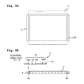
- Fig. 3A is a plane view of the platen 2 and the platen absorber 60
- Fig. 3B is a cross-sectional view of the platen 2 and the platen absorber 60 in the vertical plane including the scanning direction when the liquid is being recovered (during a liquid recovery operation).
- the recording paper P is depicted by broken lines, and the lower portion of the recording paper P is depicted in phantom. As shown in Figs.
- a platen absorber 60 having a rectangular cylindrical shape is integrated into the platen 2 at a lower portion of an area in which an end or edge portion of the recording paper P passes.
- the platen absorber 60 may be any member provided that such a member is capable of absorbing the first liquid, such as, for example, a melamine foam, etc.
- the shape of the platen absorber 60 is not limited to the shape of rectangular cylindrical shape shown in Figs. 3A and 3B , and the platen absorber 60 may have any shape provided that the platen absorber 60 is capable of absorbing the first liquid discharged beyond the end portion of the recording paper P.
- the first flushing absorber 53, the second flushing absorber 54, the waste liquid absorber 22 and the platen absorber 60 contain the second liquid containing the second 1,2-diol of which vapor pressure is lower than the vapor pressure of the first 1,2-diol contained in the first liquid.
- the second liquid containing the second 1,2-diol may be contained only at a portion which makes contact with the first liquid discharged from the ink-jet head 4, or may be contained in the entirety of each of the first and second flushing absorbers 53 and 54 and the platen absorber 60.
- each of the first flushing absorber 53, the second flushing absorber 54, and the platen absorber 60 may be provided independently (separately) respectively for the colors of the first liquids (inks) discharged from the ink-jet head 4.
- the content amounts of the second 1,2-diol contained in each of the first flushing absorber 53, the second flushing absorber 54, and the platen absorber 60 may be determined depending on the content amount of the first 1,2-diol contained in one of the discharged first liquids.
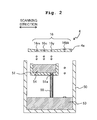
- FIG. 2 is an aspect wherein the first liquid is recovered by discharging the first liquid from the ink-jet head 4 directly to the flushing absorber.
- FIG. 2 is a cross-sectional view of the waste liquid tank 50 in a vertical plane including the scanning direction when the liquid discharge recording apparatus 1 shown in Fig. 1 performs liquid recovery operation.
- reference numerals "16bk", “16y”, “16c” and “16m” indicate nozzles 16 for the black, yellow, cyan and magenta inks, respectively.
- the ink-jet head 4 may further have a nozzle and a supply port for a treatment liquid.
- the liquid discharge recording apparatus 1 may further have a cartridge in which the treatment liquid is stored and a tube for supplying the treatment liquid.
- Fig. 2 shows an example wherein liquid recovery for recovering the black ink from the nozzle 16bk and liquid recovery for recovering the three color inks that are yellow, cyan and magenta inks from the nozzles 16y, 16c and 16m are performed at the same time.
- a timing for discharging the inks is exemplified by a timing before starting the recording on recording paper P, a timing between the paper sheets during a continuous recording (from a point of time after completing recording on one sheet of the recording paper P and until a point of time starting the recording on next sheet of the recording paper P), etc.
- the shipping liquid is discharged from the ink-jet head 4 by a purge performed by the purge unit before the liquid used for the ink-jet recording and including the ink and the treatment liquid, etc., is introduced into the flow channel, and then the shipping liquid is recovered to the waste liquid absorber 22 (is recovered by being absorbed in the waste liquid absorber 22).
- the first liquids are recovered by discharging the inks of the respective colors that are the black ink and the three color inks that area yellow, cyan and magenta inks from the nozzle 16bk of the black ink and the nozzles 16y, 16c and 16m of the three color inks toward the first flushing absorber 53 accommodated in the waste liquid tank 50 and the second flushing absorber 54 accommodated in the liquid receiving member 51, respectively, at a position at which the nozzle 16bk of the black ink is made to face or to be opposite to the first flushing absorber 53, and at which the nozzles 16y, 16c and 16m of the three color inks are made to face the second flushing absorber 54.
- liquid recovery of the liquid from the nozzle 16bk of the black ink and the liquid recovery of the liquids from the nozzles 16y, 16m, and 16c of the three color inks may be performed separately from each other. Further, in a case that the ink-jet head 4 has the nozzle for the treatment liquid, liquid recovery of the treatment liquid from the nozzle for the treatment liquid can also be performed by moving the nozzle for the treatment liquid to a position facing or to be opposite to the first or second flushing absorber 53 or 54, in a similar manner as for the recovery of the inks.
- the maximum amount of the second liquid contained in the first and second flushing absorbers 53 and 54 is preferably not more than 0.91 ⁇ g/mm 3 , and is more preferably not more than 0.7 ⁇ g/mm 3 , in view of preventing any liquid leakage (dripping) from the absorbers.
- the minimum amount of the second liquid contained in the first and second flushing absorbers 53 and 54 is preferably not less than 0.02 ⁇ g/mm 3 and is more preferably not less than 0.04 ⁇ g/mm 3 , in view of sufficiently suppressing the volatilization of the first 1,2-diol contained in the first liquid; in a case that the second liquid contains 50% by weight to 100% by weight of the non-volatile 1,2-diol, the minimum amount of the second liquid contained in the first and second flushing absorbers 53 and 54 is preferably not less than 0.01 ⁇ g/mm 3 and is more preferably not less than 0.02 ⁇ g/mm 3 .
- the amount of the second 1,2-diol in the second liquid contained in the absorber may be determined depending on, for example, the amount of the first 1,2-diol contained in the first liquid, the period of service life or lifetime of the liquid discharge recording apparatus, etc.
- the absorber is the flushing absorber of the liquid discharge recording apparatus
- the amount of the second 1,2-diol in the second liquid contained in the flushing absorber is preferably not less than 0.10 g, is more preferably not less than 0.18 g, is preferably not more than 0.81 g, and is more preferably not more than 0.63 g.
- the second liquid, containing the second 1,2-diol, of which vapor pressure is lower than that of the first 1,2-diol contained in the first liquid, is contained in the first and second flushing absorbers 53 and 54. Therefore, it is possible to reduce the volatilization of the first 1,2-diol contained in the first liquid by the above-described mechanism viewing the "coexistence effect" from the opposite standpoint.
- the liquid recovery method of the present teaching will be explained with reference to Fig. 1 .
- the first liquid (ink) sucked and made to exit by the suction purge is absorbed by the waste liquid absorber 22 via the suction pump 23.
- the maximum amount of the second liquid contained in the waste liquid absorber 22 is preferably not more than 0.91 ⁇ g/mm 3 .
- the minimum amount of the second liquid contained in the waste liquid absorber 22 is preferably not less than 0.1 ⁇ g/mm 3 and is more preferably not less than 0.2 ⁇ g/mm 3 ; in a case that the second liquid contains 50% by weight to 100% by weight of the non-volatile 1,2-diol, the minimum amount of the second liquid contained in the waste liquid absorber 22 is preferably not less than 0.05 ⁇ g/mm 3 and is more preferably not less than 0.5 ⁇ g/mm 3 .
- the waste liquid absorber 22 also contains the second liquid containing the second 1,2-diol of which vapor pressure is lower than that of the first 1,2-diol contained in the first liquid, it is possible to reduce the volatilization of the first 1,2-diol contained in the first liquid by the above-described mechanism viewing the "coexistence effect" from the opposite standpoint.
- the present teaching is applicable also to an aspect wherein the first liquid discharged from the ink-jet head 4 is absorbed by the waste liquid absorber 22 via the suction pump 23, without being limited only to the case that the first liquid discharged from the ink-jet head 4 is directly absorbed.
- FIG. 3B is an aspect wherein the first liquid is recovered by discharging the first liquid from the ink-jet head 4 directly to the platen absorber 60.
- same parts or portions as those in Fig. 2 are assigned with same reference numerals as those in Fig. 2 .
- Fig. 3B shows an example wherein the liquid (first liquid) is recovered from the nozzle 16m for the magenta ink.
- the first liquid (magenta ink) is recovered by discharging the magenta ink from the nozzle 16m of the magenta ink toward the platen absorber 60 integrated into the platen 2, at a position at which the nozzle 16m is made to face or to be opposite to the platen absorber 60.
- the recovery of the first liquids from the nozzles 16bk, 16y and 16c can also be performed by moving the nozzles 16bk, 16y and 16c to positions at each of which one of the nozzles 16bk, 16y and 16c faces the platen absorber 60, in a similar manner as for the recovery of the magenta ink from the nozzle 16m.
- liquid recovery of the treatment liquid from the nozzle for the treatment liquid can also be performed by moving the nozzle for the treatment liquid to a position facing or to be opposite to the platen absorber 60, in a similar manner as for the recovery of the ink(s).
- the maximum amount of the second liquid contained in the platen absorber 60 is preferably not more than 0.91 ⁇ g/mm 3 .
- the second liquid containing the second 1,2-diol, of which vapor pressure is lower than that of the first 1,2-diol contained in the first liquid, is contained in the platen absorber 60. Therefore, it is possible to reduce the volatilization of the first 1,2-diol contained in the first liquid by the above-described mechanism viewing the "coexistence effect" from the opposite standpoint.
- the absorber which contains the second liquid containing the second 1,2-alkanediol of which vapor pressure is lower than that of the first 1,2-alkanediol contained in the first liquid, to absorb the first liquid exited from the liquid discharge head.
- a melamine foam (surface area: 1 cm 2 , thickness: 5 mm) was placed in a vial bottle for HS-GC/MS (Head Space-Gas Chromatography/Mass Spectrometry) measurement.
- 100 ⁇ L of an ink was permeated into the melamine foam and was kept at a temperature of 60 degrees Celsius for 30 minutes.
- the pigment dispersant is CAB-O-JET (trade name) 300 produced by Cabot Corporation; and the surfactant is OLFINE (trade name) E1010 produced by Nissin Chemical Industry Co., Ltd.
- Example 6 a 50 % by weight 1,2-diol-aqeous solution of the 1,2-diol as measurement objective was used; in Example 7, a 25 % by weight 1,2-diol-aqueous solution of the 1,2-diol as measurement objective was used; in Comparative Example 1, glycerol (GLY) was used; in Comparative Example 2, triethylene glycol (TEG) was used; and in Comparative Example 3, triethylene glycol butyl ether (TEB) was used.
- GLY glycerol
- TOG triethylene glycol
- TEB triethylene glycol butyl ether
- Reduction Rate % X - Y / X x 100 wherein in the formula, X: Total of the peak areas in the ink itself Y: Total of the peak areas in a case that the compound as the measurement objective was permeated in the melamine foam.
- Ink Composition (unit: % by weight) Pigment dispersant (10% aqueous solution) 60.0 60.0 60.0 Glycerol 4.0 4.0 4.0 Triethylene glycol 4.0 4.0 4.0 Diethylene glycol 4.0 4.0 1,2-PDO 10.0 - - 1,2-BDO - 10.0 - 1,2-PeDO - - 10.0 Surfactant 0.4 0.4 0.4 Water balance balance balance
- EX.1 COM. EX. 2 COM. EX. 3 COM. EX. 4 COM. EX. 5 Ink Ink 1 Ink 1 Ink 1 Ink 2 Ink 3 1,2-diol contained in the ink 1,2-PDO 1,2-PDO 1,2-PDO 1,2-BDO 1,2-PeDO Vapor pressure (hPa-20 degrees Celsius) 0.11 0.11 0.11 0.10 0.10 Compound permeated in the melamine foam
- Example 3 wherein 1,2-PDO was permeated in the ink and 1,2-HeDO was permeated in the melamine foam, the reduction rate was not less than 80% and the volatilization of the 1,2-diol contained in the ink was furthermore lowered.
- the liquid discharge recording apparatus of the present teaching is capable of reducing the generation of VOC.
- the usage of the liquid discharge recording apparatus of the present teaching is not particularly limited, and is widely applicable to a variety of kinds of ink-jet recording.
Landscapes
- Chemical & Material Sciences (AREA)
- Engineering & Computer Science (AREA)
- Life Sciences & Earth Sciences (AREA)
- Materials Engineering (AREA)
- Wood Science & Technology (AREA)
- Organic Chemistry (AREA)
- Chemical Kinetics & Catalysis (AREA)
- Environmental & Geological Engineering (AREA)
- Ink Jet (AREA)
Abstract
Description
- The present invention relates to a liquid discharge recording apparatus and a method for recovering liquid.
- Conventionally, a water-based ink for ink-jet recording (hereinafter referred to as a "water-based ink" or an "ink" in some cases) has been using, as a solvent, a volatile organic solvent (see, for example, Japanese Patent Application Laid-open No.
2003-147243 2003-128969 - In the recent years, there is an increased demand for further reducing the generation of VOC as the consumption of ink is increased due to, for example, the improvement in recording speed. On the other hand, in a case that a non-volatile organic solvent is added to a water-based ink as the countermeasure against the VOC, the quick-drying property during recording and the spreading into a recording medium such as a recording paper (recording sheet), etc., are not sufficient, making it difficult to satisfy the property or performance as a water-based ink adapted for a high-speed recording. In view of the situation described above, there is a demand for a liquid discharge recording apparatus, such as an ink-jet recording apparatus, which is adapted to the high-speed recording as well as capable of further reducing the generation of VOC more than the conventional technique.
- An object of the present teaching is to provide a liquid discharge recording apparatus and a method for recovering a liquid which are capable of reducing the generation of VOC.
- According to a first aspect of the present teaching, there is provided a liquid discharge recording apparatus including:
- a first liquid containing first 1,2-alkanediol;
- a liquid discharge head configured to discharge the first liquid;
- a second liquid containing second 1,2-alkanediol of which vapor pressure is lower than that of the first 1,2-alkanediol; and
- an absorber which contains the second liquid and which is configured to absorb the first liquid exited from the liquid discharge head.
- According to a second aspect of the present teaching, there is provided a liquid-recovery method for recovering a liquid in a liquid discharge recording apparatus, the method including:
- causing a first liquid containing first 1,2-alkanediol to exit from a liquid discharge head of the liquid discharge recording apparatus; and
- recovering the first liquid by absorbing the first liquid exited from the liquid discharge head with an absorber which is provided in the liquid discharge recording apparatus and which contains a second liquid containing second 1,2-alkanediol having lower vapor pressure than that of the first 1,2-alkanediol.
-
-
Fig. 1 is a schematic plane view showing the configuration of an example of a liquid discharge recording apparatus of the present teaching. -
Fig. 2 is a cross-sectional view of a waste liquid tank in a vertical plane including the scanning direction when the liquid discharge recording apparatus shown inFig. 1 performs liquid recovery operation. -
Fig. 3A is a plane view of a platen and a platen absorber of the liquid discharge recording apparatus shown inFig. 1 , andFig. 3B is a cross-sectional view of the platen and the platen absorber in the vertical plane including the scanning direction when the liquid discharge recording apparatus shown inFig. 1 performs liquid recovery operation. - A liquid discharge recording apparatus of the present teaching includes a first liquid containing first 1,2-alkanediol, a liquid discharge head configured to discharge the first liquid, and an absorber which contains a second liquid containing second 1,2-alkanediol and which is configured to absorb the first liquid exited from the liquid discharge head. The vapor pressure of the second 1,2-alkanediol is lower than the vapor pressure of the first 1,2-alkanediol. In the following description of the present specification, the "1,2-alkanediol" is referred to also as "1,2-diol" in some cases. Further, in the specification, "the first liquid exited from the liquid discharge head" includes the first liquid which is discharged actively and made to exit from the nozzles, and the first liquid which is forced to exit from the nozzles as in the suction purge or push purge.
- The first liquid usable in the liquid discharge recording apparatus of the present teaching includes, for example, a water-based ink for ink-jet recording, a treatment solution (treatment liquid) used in the ink-jet recording, etc. The treatment liquid is a liquid which is discharged to a recording medium before or after the discharge of ink, for the purpose of improving the quality of image (image quality), etc. Further, the first liquid is not limited to a liquid to be used for ink-jet recording, and is exemplified by, for example, a shipping liquid (preservative liquid), an introductory liquid, an inspection liquid, etc. The shipping liquid is a liquid charged into a flow channel, of a liquid discharge recording apparatus, in a state of shipped out from the factory so as to preserve that state inside the flow channel. The introductory liquid is a liquid which is charged in advance into the flow channel of the liquid discharge recording apparatus after a liquid discharge head of the apparatus has been produced such that, when the ink is introduced into the flow channel in the factory, the ink is easily introduced into the flow channel. The inspection liquid is a liquid to be used for inspecting the discharge of the liquid discharge head in the factory. As described above, the first liquid contains the first 1,2-diol. It is allowable to prepare the first liquid or to use any commercially available liquid product which contains the first 1,2-diol.
- According to the present teaching, it is possible to reduce the volatilization of the first 1,2-diol contained in the first liquid. Therefore, for example, it is possible to add a necessary and sufficient amount of the first 1,2-diol to an ink applied to the liquid discharge recording apparatus of the present teaching, thereby making it possible to improve the quick-drying property and the image quality as well. Further, 1,2-diol also has the surface-active property. Accordingly, the first liquid containing the necessary and sufficient amount of the first 1,2-diol can be easily introduced into the liquid discharge head and the flow channel of the liquid discharge recording apparatus. Note that the above-described effect obtained by the first 1,2-alkanediol contained in the first liquid cannot be obtained with any alkanediols different from 1,2-alkanediol such as, for example, 1,5-pentanediol, 1,6-hexanediol, etc. Further, the alkanediols different from 1,2-alkanediol have low vapor pressure lower than that of 1,2-alkanediol, in many cases. Thus, even if any of the alkanediols different from 1,2-alkanediol is contained in the first liquid, there is no task that is same as that of the present teaching and that is to suppress the volatilization of the alkanediol different from 1,2-alkanediol.
- There is known the "coexistence effect" wherein a substance having a low vapor pressure is allowed to coexist with a substance having a high vapor pressure, thereby making it possible to volatilize the substance having the low vapor pressure. The present teaching views this "coexistence effect" from the opposite standpoint, and is based on a concept that the volatilization of the first 1,2-diol contained in the first liquid is reduced by allowing the absorber to contain the second liquid containing the second 1,2-diol of which vapor pressure is lower than that of the first 1,2-diol contained in the first liquid. The inventors of the present teaching were the first to obtain this concept. Base on the concept, the inventors of the present teaching found out that the volatilization of the first 1,2-diol contained in the first liquid can be reduced by absorbing the first liquid with the absorber containing the second liquid containing the second 1,2-diol of which vapor pressure is lower than that of the first 1,2-diol contained in the first liquid. Thus, according to the present teaching, it is possible to provide a liquid discharge recording apparatus and a liquid recovery method which are capable of reducing the generation of VOC. Note that since the vapor pressure depends on the temperature, the comparison between the vapor pressure of the first 1,2-diol and the vapor pressure of the second 1,2-diol in the specification of the present teaching is, naturally, performed by comparing the respective vapor pressures at a same temperature, and the comparison of the vapor pressures may be performed, for example, at 20 degrees Celsius. The method for causing the absorber to absorb the first liquid is not particularly limited; it is allowable, for example, to cause the absorber to absorb the first liquid by discharging the first liquid toward the absorber by a liquid discharge head such as an ink-jet head or to allow the absorber to absorb the first liquid sucked from the liquid discharge head by a suction pump, as will be described below.
- In the liquid discharge recording apparatus of the present teaching, the first 1,2-diol contained in the first liquid is preferably a volatile 1,2-diol, and the second 1,2-diol contained in the second liquid contained in the absorber is preferably a non-volatile 1,2-diol. Each of the first and second 1,2-diols is not a solid insoluble to water, but has the solubility to water.
- Note that it is possible to confirm whether 1,2-diol is volatile or non-volatile by, for example, the following method. Namely, at first, 5g of 1,2-diol is poured into an open container (open vial, opening size (diameter): 20.2 mm). Then, the open vial is stored for one week at a temperature of 60 degrees Celsius and a relative humidity of 40%. After the storage, in a case that the evaporation rate of the 1,2-diol exceeded 5%, such 1,2-diol is judged to be volatile, and in a case that the evaporation rate of the 1,2-diol is not more than 5%, such 1,2-diol is judged to be non-volatile. TABLE 1 shows the results of volatility confirmation for representative 1,2-diols confirmed by this method.
TABLE 1 1,2-diol 1,2-propanediol (1,2-PDO) 1,2-butane diol (1,2-BDO) 1,2-pentane diol (1,2-PeDO) 1,2-hexane diol (1,2-HeDO) Vapor pressure (20° degrees Celsius) 0.11 hPa 0.10 hPa 0.10 hpa < 0.01 hPa Molecular weight 76.1 90.1 104.2 118.2 Boiling point (degrees Celsius) 187.3 190.5 210.0 223.5 Evaporation rate (%) 61.0 47.2 38.6 4.3 Results of confirmation volatile volatile volatile non-volatile - The volatile 1,2-diol includes, for example, 1,2-propanediol (1,2-PDO), 1,2-butane diol (1,2-BDO), 1,2-pentane diol (1,2-PeDO), etc. The volatile 1,2-diol is preferably 1,2-PDO. It is allowable that only one kind of the above volatile 1,2-diols is contained in the first liquid, or that two or more kinds of the above volatile 1,2-diols are contained in the first liquid.
- The non-volatile 1,2-diol includes, for example, 1,2-hexane diol (1,2-HeDO), 1,2-heptanol, 1,2-octanediol, 1,2-nonanediol, 1,2-decanediol, etc. It is allowable that only one kind of the above non-volatile 1,2-diols is contained in the second liquid, or that two or more kinds of the above non-volatile 1,2-diols are contained in the second liquid.
- Note that since the carbon numbers of the 1,2-propanediol (1,2-PDO), 1,2-butane diol (1,2-BDO), 1,2-pentane diol (1,2-PeDO), 1,2-hexane diol (1,2-HeDO), 1,2-heptanol, 1,2-octanediol, 1,2-nonanediol and 1,2-decanediol increase in the order that these 1,2-diols are listed as above, the vapor pressures in these 1,2-diols lower also in the listed order.
- It is preferable that each of the first and second 1,2-alkanediols is straight-chain alkanediol. The above-described effect viewing the "coexistence effect" from the opposite standpoint tends to easily occur between substances having similar chemical structures. Thus, in a case that each of the first and second 1,2-alkanediols is straight-chain alkanediol, it is possible to lower the volatilization of the first 1,2-alkanediol contained in the first liquid more effectively.
- It is preferable that the carbon number of each of the first and second 1,2-alkanediols is 3 to 10. In a case that the carbon number of the first 1,2-alkanediol is not less than 3, the effects such as the realization of quick-drying property and improved image quality and also the effect of realizing easy introduction of the first liquid into the liquid discharge head, etc. are easily achieved; in a case that the carbon number of each of the first and second 1,2-alkanediols is not more than 10, the sufficient solubility of each of the first and second 1,2-alkanediols to water can be ensured.
- The vapor pressure of 1,2-alkanediol tends to be lower as the carbon number of 1,2-alkanediol is great. Thus, it is preferable that the carbon number of the first 1,2-alkanediol is smaller than the carbon number of the second 1,2-alkanediol. It is further preferable that the carbon number of the first 1,2-alkanediol is 3 to 5 and that the carbon number of the second 1,2-alkanediol is 6 to 10.
- In a case that the first liquid is an ink, at least one of a dye and a pigment may be added as a colorant to the first liquid. The blending amount of the colorant in the entire amount of the ink is not particularly limited, and may be appropriately determined based on, for example, desired optical density or color (hue, tint), etc. The blending amount of the colorant in the entire amount of the ink is, for example, in a range of 0.2% by weight to 20% by weight, and is preferably in a range of 2% by weight to 10% by weight. The blending amount of the first 1,2-diol in the entire amount of the ink is not particularly limited, and is, for example, in a range of 0.5% by weight to 15% by weight, is preferably in a range of 1% by weight to 10% by weight, and is more preferably in a range of 2% by weight to 5% by weight. The ink may further contain any other conventionally known additive(s) exemplified by surfactants, rust-preventing agents, fungicides, etc., as necessary.
- In a case that the first liquid is an introductory liquid, the blending amount of the first 1,2-diol in the entire amount of the introductory liquid is not particularly limited, and is preferably in a range of 2% by weight to 30% by weight, in view of the introductory performance of the introductory liquid, and is more preferably in a range of 5% by weight to 15% by weight.
- In a case that the first liquid is a shipping liquid (preservative liquid), the blending amount of the first 1,2-diol in the entire amount of the shipping liquid is not particularly limited, and is, for example, in a range of 0.5% by weight to 10% by weight, is preferably in a range of 1% by weight to 7.5% by weight, and is more preferably in a range of 2% by weight to 5% by weight.
- In a case that the first liquid is an inspection liquid, the blending amount of the first 1,2-diol in the entire amount of the inspection liquid is not particularly limited, and is, for example, in a range of 1% by weight to 20% by weight, is preferably in a range of 2% by weight to 15% by weight, and is more preferably in a range of 5% by weight to 10% by weight. The inspection liquid may contain a colorant similar to the colorant contained in the ink.
- In a case that the first liquid is a liquid different from the ink, such as the introductory liquid, preservative liquid (shipping liquid), inspection liquid, etc., it is allowable that the first liquid does not contain any colorant, or that the first liquid contains a colorant so that the presence of the first liquid can be visually confirmed. In a case that the first liquid which is different from the ink contains a colorant, the blending amount of the colorant in the first liquid is preferably not more than 0.5% by weight.
- In the liquid discharge recording apparatus of the present teaching, the absorber which absorbs the first liquid exited from the liquid discharge head may be any absorber provided that the absorber is capable of absorbing the first liquid. For example, the absorber is exemplified by melamine foam, urethane foam, polyethylene foam, silicone foam, acrylic foam, chloroprene rubber (CR) sponge, natural rubber (NR) sponge, nitrile rubber (NBR) sponge, ethylene propylene diene rubber (EPDM) sponge, felt foam, needle felt among which melamine foam is preferable.
- The second 1,2-alkanediol in the second liquid contained in the absorber may be any 1,2-alkanediol provided that the vapor pressure of such 1,2-alkanediol is lower than the vapor pressure of the first 1,2-alkanediol. It is preferable, however, that the second 1,2-alkanediol is non-volatile 1,2-alkanediol as described above. Further, it is allowable that the second 1,2-alkanediol is composed substantially only of non-volatile 1,2-alkanediol and does not contain any volatile 1,2-alkanediol. Even in a case that the absorber contains any volatile 1,2-alkanediol, the ratio of the non-volatile 1,2-alkanediol to the entire amount of 1,2-alkanediols contained in the absorber is preferably not less than 95% by weight.
- It is preferable that the second liquid is composed only of the second 1,2-alkanediol, or that the second liquid contains another solvent, such as water, that is different from the second 1,2-alkanediol. The second liquid may be an aqueous solution of the second 1,2-alkanediol. The water is preferably ion exchange water or pure water (purified water). In view of reducing the volatilization of the first 1,2-alkanediol, the blending amount of the second 1,2-alkanediol in the second liquid is preferably, for example, in a range of 20% by weight to 100% by weight, is more preferably in a range of 50% by weight to 100% by weight, and is further more preferably in a range of 80% by weight to 100% by weight. Further, in view of reducing the volatilization of the first 1,2-alkanediol, the blending ratio (% by weight) of the second 1,2-alkanediol in the second liquid is preferably not less than 2.5 times, is more preferably in a range of 2.5 times to 10 times the blending ratio (% by weight) of the first 1,2-alkanediol in the first liquid.
- Next, a liquid discharge recording apparatus and a liquid recovery method of the present teaching will be specifically explained. The liquid discharge recording apparatus of the present teaching includes a liquid discharge head which discharges the first liquid and an absorber which absorbs the first liquid exited from the liquid discharge head. The absorber is preferably at least one of a flushing absorber, a waste liquid absorber and a platen absorber, wherein the flushing absorber is arranged in a non-recording area of the liquid discharge recording apparatus, the waste liquid absorber directly or indirectly absorbs the first liquid exited from the liquid discharge head and stores the first liquid therein, and the platen absorber is arranged in a recording area of the liquid discharge recording apparatus. In the liquid discharge recording apparatus of the present teaching, the configuration of the liquid discharge recording apparatus, except for the absorber, may be similar to that of a conventional liquid discharge recording apparatus such as an ink-jet recording apparatus. The liquid recovery method of the present teaching is practiced by using the liquid discharge recording apparatus of the present teaching.
-
Fig. 1 shows the configuration of an example of the liquid discharge recording apparatus of the present teaching. As shown inFig. 1 , a liquid discharge recording apparatus 1 of the present teaching includes aplaten 2, a carriage 3, an ink-jet head (liquid discharge head) 4, a transportingmechanism 5 and a maintenance unit 6 as main constitutive components or parts. The ink-jet head 4 may be of any system including the piezoelectric element system, the thermal ink-jet system, the electrostatic attraction system, etc. - A recording medium (for example, recording paper or recording sheet) P supplied from a paper feeding mechanism (not shown in the drawings) is placed on the upper surface of the
platen 2. Twoguide rails platen 2, and extend parallel to each other in the scanning direction (left/right direction inFig. 1 ). The carriage 3 is movable in a reciprocating manner in the scanning direction along the twoguide rails platen 2. - The two
guide rails platen 2. The carriage 3 is configured to be movable from the area facing the recording paper P on the platen 2 (recording area) to a position located away from both of the left/right ends of the platen 2 (non-recording area). Anendless belt 14 wound between twopulleys endless belt 14 to run by acarriage driving motor 15, the carriage 3 is reciprocated in the scanning direction, accompanying with the running of theendless belt 14. - The ink-
jet head 4 is installed in a lower portion of the carriage 3. The lower surface of the ink-jet head 4 is aliquid discharge surface 4a (seeFig. 2 ) which is parallel to the upper surface of theplaten 2 and in which a plurality ofnozzles 16 are opened. The first liquid (ink) is discharged from the plurality ofnozzles 16 of theliquid discharge surface 4a toward the recording paper P placed on theplaten 2 so as to perform recording on the recording paper P. - Four ink supply ports (not shown in the drawings) corresponding to colors of black, yellow, cyan and magenta, respectively are provided on the upper surface of the ink-
jet head 4, and one ends of fourtubes 17 are connected to the four ink supply ports, respectively. The other ends of the fourtubes 17 are connected to a cartridge installation section 9 that is configured such that fourink cartridges 8 storing the four color inks respectively are detachably attached to the cartridge installation section 9. With this configuration, the inks of the respective four colors are supplied to the ink-jet head 4 from the fourink cartridges 8 installed in the cartridge installation section 9 via the fourtubes 17, respectively. - The transporting
mechanism 5 has two transportingrollers platen 2 therebetween in a transporting direction (direction from the upper portion to the lower portion on the sheet surface inFig. 1 ). The recording paper P placed on theplaten 2 is transported in the transporting direction by the two transportingrollers - The liquid discharge recording apparatus 1 discharges the first liquid from the ink-
jet head 4 installed in the carriage 3 toward the recording paper P placed on theplaten 2 and transports the recording paper P in the transporting direction by the two transportingrollers - Next, the maintenance unit 6 will be explained. The maintenance unit 6 includes a purge unit and a flushing unit. The purge unit has a
waste liquid absorber 22, asuction cap 21 and asuction pump 23 which are arranged on one side in the scanning direction (on the right side inFig. 1 ) with respect to theplaten 2. The flushing unit is arranged on the other side in the scanning direction (on the left side inFig. 1 ) with respect to theplaten 2, and includes afirst flushing absorber 53, asecond flushing absorber 54, awaste liquid tank 50 and aliquid receiving member 51, as main constitutive components or parts. - The
suction cap 21 is driven by a cap driving mechanism including a driving mechanism such as a motor (not shown) so that thesuction cap 21 is driven to move in the up and down direction and to make approach/separation with respect to theliquid discharge surface 4a. Thesuction pump 23 is connected to thesuction cap 21. When thesuction cap 21 makes contact with theliquid discharge surface 4a, thesuction cap 21 covers the openings of the plurality ofnozzles 16. In a case that thesuction cap 21 is in a capping state in such a manner, thesuction pump 23 is driven to perform suction and depressurization in the inside of thesuction cap 21, thereby causing the first liquid to exit from all of thenozzles 16 covered by the suction cap 21 (suction purge). Thesuction pump 23 is connected to thewaste liquid absorber 22. The first liquid sucked and made to exit from thenozzles 16 by the suction purge is absorbed by thewaste liquid absorber 22 via thesuction pump 23. Although not shown in the drawings, thewaste liquid absorber 22 is accommodated in a box which is open at an upper portion of the box. Thewaste liquid absorber 22 may be any member provided that such a member is capable of absorbing the first liquid, such as, for example, a melamine foam, etc. In the embodiment, the purge unit is configured to suck the first liquid from thenozzles 16 by thesuction pump 23. However, the purge unit may be configured as a so-called "push purge" mechanism which applies pressure to the first liquid inside the ink-jet head 4 to thereby cause the first liquid to exit from thenozzles 16. Namely, the first liquid absorbed by the absorber in the present teaching may be the first liquid which is discharged actively and made to exit from the nozzles, or the first liquid which is forced to exit from the nozzles as in the suction purge. Alternatively, in the present teaching, it is allowable to provide such an aspect wherein the absorber receives the first liquid discharged directly to the absorber, or another aspect wherein the absorber, such as thewaste liquid absorber 22, receives the first liquid indirectly, e.g. the first liquid fed from thesuction pump 23, etc. to the absorber. - As shown in
Fig. 2 , thewaste liquid tank 50 has a box-shape which is open at an upper portion thereof, and accommodates thefirst flushing absorber 53 inside of thewaste liquid tank 50. Theliquid receiving member 51 is arranged at a position above or over thefirst flushing absorber 53. Theliquid receiving member 51 has a box-shape which is open at an upper portion thereof, and accommodates thesecond flushing absorber 54 inside of theliquid receiving member 51. Adischarge port 51a is formed in theliquid receiving member 51 at a portion on the bottom surface and located on one side in the scanning direction (on the right side inFig. 2 ). Thedischarge port 51a is connected to one end of atube 55 of which other end makes contact with the upper surface of thefirst flushing absorber 53. With this, the first liquid absorbed by the upper surface of thesecond flushing absorber 54 moves downwardly and is discharged from thedischarge port 51a to thefirst flushing absorber 53, via thetube 55. Each of the first andsecond flushing absorbers - Next, a
platen absorber 60 will be explained with reference toFigs. 3A and 3B. Fig. 3A is a plane view of theplaten 2 and theplaten absorber 60, andFig. 3B is a cross-sectional view of theplaten 2 and theplaten absorber 60 in the vertical plane including the scanning direction when the liquid is being recovered (during a liquid recovery operation). Note that inFig. 3A , the recording paper P is depicted by broken lines, and the lower portion of the recording paper P is depicted in phantom. As shown inFigs. 3A and 3B , aplaten absorber 60 having a rectangular cylindrical shape is integrated into theplaten 2 at a lower portion of an area in which an end or edge portion of the recording paper P passes. With this, in case of performing for example a borderless recording with respect to the recording paper P, it is possible to absorb, with theplaten absorber 60, the first liquid discharged onto the upper surface of theplaten 2 beyond the end portion of the recording paper P. Theplaten absorber 60 may be any member provided that such a member is capable of absorbing the first liquid, such as, for example, a melamine foam, etc. Further, the shape of theplaten absorber 60 is not limited to the shape of rectangular cylindrical shape shown inFigs. 3A and 3B , and theplaten absorber 60 may have any shape provided that theplaten absorber 60 is capable of absorbing the first liquid discharged beyond the end portion of the recording paper P. - The
first flushing absorber 53, thesecond flushing absorber 54, thewaste liquid absorber 22 and theplaten absorber 60 contain the second liquid containing the second 1,2-diol of which vapor pressure is lower than the vapor pressure of the first 1,2-diol contained in the first liquid. In each of the first andsecond flushing absorbers platen absorber 60, the second liquid containing the second 1,2-diol may be contained only at a portion which makes contact with the first liquid discharged from the ink-jet head 4, or may be contained in the entirety of each of the first andsecond flushing absorbers platen absorber 60. Further, each of thefirst flushing absorber 53, thesecond flushing absorber 54, and theplaten absorber 60 may be provided independently (separately) respectively for the colors of the first liquids (inks) discharged from the ink-jet head 4. In such a case, the content amounts of the second 1,2-diol contained in each of thefirst flushing absorber 53, thesecond flushing absorber 54, and theplaten absorber 60 may be determined depending on the content amount of the first 1,2-diol contained in one of the discharged first liquids. - Next, an example of the liquid recovery method of the present teaching will be explained with reference to
Fig. 2 . The example shown inFig. 2 is an aspect wherein the first liquid is recovered by discharging the first liquid from the ink-jet head 4 directly to the flushing absorber.Fig. 2 is a cross-sectional view of thewaste liquid tank 50 in a vertical plane including the scanning direction when the liquid discharge recording apparatus 1 shown inFig. 1 performs liquid recovery operation. InFig. 2 , reference numerals "16bk", "16y", "16c" and "16m" indicatenozzles 16 for the black, yellow, cyan and magenta inks, respectively. In the liquid discharge recording apparatus 1, the ink-jet head 4 may further have a nozzle and a supply port for a treatment liquid. The liquid discharge recording apparatus 1 may further have a cartridge in which the treatment liquid is stored and a tube for supplying the treatment liquid. - When the liquid is recovered in this example, the ink-
jet head 4 is stopped, without scanning in the scanning direction, and the inks discharged from thenozzles 16 are discharged immediately downwardly.Fig. 2 shows an example wherein liquid recovery for recovering the black ink from the nozzle 16bk and liquid recovery for recovering the three color inks that are yellow, cyan and magenta inks from thenozzles jet head 4, the shipping liquid is discharged from the ink-jet head 4 by a purge performed by the purge unit before the liquid used for the ink-jet recording and including the ink and the treatment liquid, etc., is introduced into the flow channel, and then the shipping liquid is recovered to the waste liquid absorber 22 (is recovered by being absorbed in the waste liquid absorber 22). - In
Fig. 2 , the first liquids (inks) are recovered by discharging the inks of the respective colors that are the black ink and the three color inks that area yellow, cyan and magenta inks from the nozzle 16bk of the black ink and thenozzles first flushing absorber 53 accommodated in thewaste liquid tank 50 and thesecond flushing absorber 54 accommodated in theliquid receiving member 51, respectively, at a position at which the nozzle 16bk of the black ink is made to face or to be opposite to thefirst flushing absorber 53, and at which thenozzles second flushing absorber 54. Note that the liquid recovery of the liquid from the nozzle 16bk of the black ink and the liquid recovery of the liquids from thenozzles jet head 4 has the nozzle for the treatment liquid, liquid recovery of the treatment liquid from the nozzle for the treatment liquid can also be performed by moving the nozzle for the treatment liquid to a position facing or to be opposite to the first orsecond flushing absorber second flushing absorbers second flushing absorbers second flushing absorbers - Furthermore, the amount of the second 1,2-diol in the second liquid contained in the absorber may be determined depending on, for example, the amount of the first 1,2-diol contained in the first liquid, the period of service life or lifetime of the liquid discharge recording apparatus, etc. For example, in a case that the absorber is the flushing absorber of the liquid discharge recording apparatus, the amount of the second 1,2-diol in the second liquid contained in the flushing absorber is preferably not less than 0.10 g, is more preferably not less than 0.18 g, is preferably not more than 0.81 g, and is more preferably not more than 0.63 g.
- The second liquid, containing the second 1,2-diol, of which vapor pressure is lower than that of the first 1,2-diol contained in the first liquid, is contained in the first and
second flushing absorbers - Next, another example of the liquid recovery method of the present teaching will be explained with reference to
Fig. 1 . As described above, in the liquid discharge recording apparatus 1 shown inFig. 1 , the first liquid (ink) sucked and made to exit by the suction purge is absorbed by thewaste liquid absorber 22 via thesuction pump 23. The maximum amount of the second liquid contained in thewaste liquid absorber 22 is preferably not more than 0.91 µg/mm3. In a case that the second liquid contains 25% by weight to 100% by weight of the non-volatile 1,2-diol, the minimum amount of the second liquid contained in thewaste liquid absorber 22 is preferably not less than 0.1 µg/mm3 and is more preferably not less than 0.2 µg/mm3; in a case that the second liquid contains 50% by weight to 100% by weight of the non-volatile 1,2-diol, the minimum amount of the second liquid contained in thewaste liquid absorber 22 is preferably not less than 0.05 µg/mm3 and is more preferably not less than 0.5 µg/mm3. Since thewaste liquid absorber 22 also contains the second liquid containing the second 1,2-diol of which vapor pressure is lower than that of the first 1,2-diol contained in the first liquid, it is possible to reduce the volatilization of the first 1,2-diol contained in the first liquid by the above-described mechanism viewing the "coexistence effect" from the opposite standpoint. In such a manner, the present teaching is applicable also to an aspect wherein the first liquid discharged from the ink-jet head 4 is absorbed by thewaste liquid absorber 22 via thesuction pump 23, without being limited only to the case that the first liquid discharged from the ink-jet head 4 is directly absorbed. - Next, still another example of the liquid recovery method of the present teaching will be explained with reference to
Fig. 3B . The example shown inFig. 3B is an aspect wherein the first liquid is recovered by discharging the first liquid from the ink-jet head 4 directly to theplaten absorber 60. InFig. 3B , same parts or portions as those inFig. 2 are assigned with same reference numerals as those inFig. 2 . - When the liquid is recovered in this example, the ink-
jet head 4 is stopped, without scanning in the scanning direction, and the ink(s) discharged from thenozzles 16 are discharged immediately downwardly.Fig. 3B shows an example wherein the liquid (first liquid) is recovered from thenozzle 16m for the magenta ink. - In
Fig. 3B , the first liquid (magenta ink) is recovered by discharging the magenta ink from thenozzle 16m of the magenta ink toward theplaten absorber 60 integrated into theplaten 2, at a position at which thenozzle 16m is made to face or to be opposite to theplaten absorber 60. Note that the recovery of the first liquids from the nozzles 16bk, 16y and 16c can also be performed by moving the nozzles 16bk, 16y and 16c to positions at each of which one of the nozzles 16bk, 16y and 16c faces theplaten absorber 60, in a similar manner as for the recovery of the magenta ink from thenozzle 16m. Further, in a case that the ink-jet head 4 has the nozzle for the treatment liquid, liquid recovery of the treatment liquid from the nozzle for the treatment liquid can also be performed by moving the nozzle for the treatment liquid to a position facing or to be opposite to theplaten absorber 60, in a similar manner as for the recovery of the ink(s). The maximum amount of the second liquid contained in theplaten absorber 60 is preferably not more than 0.91 µg/mm3. - The second liquid containing the second 1,2-diol, of which vapor pressure is lower than that of the first 1,2-diol contained in the first liquid, is contained in the
platen absorber 60. Therefore, it is possible to reduce the volatilization of the first 1,2-diol contained in the first liquid by the above-described mechanism viewing the "coexistence effect" from the opposite standpoint. - As described above, according to the present teaching, it is possible to reduce the volatilization of the first 1,2-alkanediol contained in the first liquid, by causing the absorber, which contains the second liquid containing the second 1,2-alkanediol of which vapor pressure is lower than that of the first 1,2-alkanediol contained in the first liquid, to absorb the first liquid exited from the liquid discharge head.
- Next, examples of the present teaching will be explained together with comparative examples. Note that the present teaching is not limited and is not restricted to the examples and the comparative examples which will be described below.
- A melamine foam (surface area: 1 cm2, thickness: 5 mm) was placed in a vial bottle for HS-GC/MS (Head Space-Gas Chromatography/Mass Spectrometry) measurement. Next, 100 µL of an ink was permeated into the melamine foam and was kept at a temperature of 60 degrees Celsius for 30 minutes. As the ink, each of three kinds of inks having compositions shown in TABLE 2 as follows was used. In TABLE 2, the pigment dispersant is CAB-O-JET (trade name) 300 produced by Cabot Corporation; and the surfactant is OLFINE (trade name) E1010 produced by Nissin Chemical Industry Co., Ltd. After the temperature keeping, gas was supplied from the vial bottle to the GS/MS for 0.05 minutes and the measurement was performed. Thus, the total of the peak areas of the 1,2-diols contained in the inks were calculated. Further, the melamine foam was placed in a vial bottle for the HS-GC/MS measurement. Next, 100 µL of each of 1,2-diols (a 100 % by weight 1,2-diol-aqueous solution) as measurement objectives was permeated into the melamine foam, and then 100 µL of one of the inks was permeated into the melamine foam. Thus, the total of the peak areas of the 1,2-diols contained in the inks were calculated, in a similar manner as described above. Note that in Example 6, a 50 % by weight 1,2-diol-aqeous solution of the 1,2-diol as measurement objective was used; in Example 7, a 25 % by weight 1,2-diol-aqueous solution of the 1,2-diol as measurement objective was used; in Comparative Example 1, glycerol (GLY) was used; in Comparative Example 2, triethylene glycol (TEG) was used; and in Comparative Example 3, triethylene glycol butyl ether (TEB) was used.
- Furthermore, the reduction rate of the volatilization amount of the 1,2-diol contained in the ink was calculated for each of the examples and the comparative examples by the following formula. With such a model experiment, the degree of suppressing the volatilization by the combination of the 1,2-diol contained in the ink and the compound permeated in the melamine foam was confirmed.

wherein in the formula,
X: Total of the peak areas in the ink itself
Y: Total of the peak areas in a case that the compound as the measurement objective was permeated in the melamine foam.TABLE 2 INKS Ink 1 Ink 2Ink 3 Ink Composition (unit: % by weight) Pigment dispersant (10% aqueous solution) 60.0 60.0 60.0 Glycerol 4.0 4.0 4.0 Triethylene glycol 4.0 4.0 4.0 Diethylene glycol 4.0 4.0 4.0 1,2-PDO 10.0 - - 1,2-BDO - 10.0 - 1,2-PeDO - - 10.0 Surfactant 0.4 0.4 0.4 Water balance balance balance - The results of measurement of Examples 1-7 and Comparative Examples 1-5 are shown in TABLE 3 and TABLE 4 as follows.
TABLE 3 EXAMPLES EX.1 EX.2 EX.3 EX.4 EX.5 EX.6 EX.7 Ink Ink 1 Ink 1 Ink 1 Ink 2Ink 3 Ink 1 Ink 1 1,2-diol contained in the ink 1,2-PDO 1,2-PDO 1,2-PDO 1,2-BDO 1,2-PeDO 1,2-PDO 1,2-PDO Vapor pressure (hPa-20 degrees Celsius) 0.11 0.11 0.11 0.10 0.10 0.11 0.11 1,2-diol permeated in the melamine foam 1,2-BDO 1,2-PeDO 1,2-HeDO 1,2-HeDO 1,2-HeDO 1,2-HeDO (*1) 1,2-HeDO (*2) Vapor pressure (hPa-20 degrees Celsius) 0.10 0.10 < 0.01 < 0.01 < 0.01 < 0.01 <0.01 Reduction rate (%) 23 39 82 74 70 70 45 *1: 50% by weight aqueous solution
*2: 25% by weight aqueous solutionTABLE 4 COMPARATIVE EXAMPLES COM. EX.1 COM. EX. 2 COM. EX. 3 COM. EX. 4 COM. EX. 5 Ink Ink 1 Ink 1 Ink 1 Ink 2Ink 3 1,2-diol contained in the ink 1,2-PDO 1,2-PDO 1,2-PDO 1,2-BDO 1,2-PeDO Vapor pressure (hPa-20 degrees Celsius) 0.11 0.11 0.11 0.10 0.10 Compound permeated in the melamine foam GLY TEG TEB 1,2-PDO 1,2-PDO Vapor pressure (hPa-20 degrees Celsius) <0.01 < 0.01 < 0.01 0.11 0.11 Reduction rate (%) 2 1 9 -1 -3 - As shown in TABLE 3, in Examples 1-7 wherein 1,2-diol of which vapor pressure was lower than that of 1,2-diol contained in the ink was permeated in the melamine foam, the reduction rate was not less than 20% and the volatilization of the 1,2-diol contained in the ink was lowered. In Examples 3 to 6 wherein volatile 1,2-diol was permeated in the ink and non-volatile 1,2-diol was permeated in the melamine foam, the reduction rate was not less than 50% and the volatilization of the 1,2-diol contained in the ink was further lowered. In particular, in Example 3 wherein 1,2-PDO was permeated in the ink and 1,2-HeDO was permeated in the melamine foam, the reduction rate was not less than 80% and the volatilization of the 1,2-diol contained in the ink was furthermore lowered.
- On the other hand, in each of Comparative Examples 1-3 wherein the compound different from the 1,2-diol was contained (permeated) in the melamine foam, and in Comparative Examples 4 and 5 wherein 1,2-diol of which vapor pressure is higher than that of 1,2-diol contained in the ink was permeated in the melamine foam, the reduction rate was less than 10% and the 1,2-diol contained in the ink was volatilized.
- As described above, the liquid discharge recording apparatus of the present teaching is capable of reducing the generation of VOC. The usage of the liquid discharge recording apparatus of the present teaching is not particularly limited, and is widely applicable to a variety of kinds of ink-jet recording.
Claims (15)
- A liquid discharge recording apparatus comprising:a first liquid containing first 1,2-alkanediol;a liquid discharge head configured to discharge the first liquid;a second liquid containing second 1,2-alkanediol of which vapor pressure is lower than that of the first 1,2-alkanediol; andan absorber which contains the second liquid and which is configured to absorb the first liquid exited from the liquid discharge head.
- The liquid discharge recording apparatus according to claim 1, wherein the first 1,2-alkanediol is volatile 1,2-alkanediol, and the second 1,2-alkanediol is non-volatile 1,2-alkanediol.
- The liquid discharge recording apparatus according to claim 2, wherein the volatile 1,2-alkanediol includes at least one selected from the group consisting of: 1,2-propanediol, 1,2-butanediol and 1,2-pentanediol; and
the non-volatile 1,2-alkanediol includes 1,2-hexanediol. - The liquid discharge recording apparatus according to claim 2, wherein the volatile 1,2-alkanediol includes 1,2-propanediol; and
the non-volatile 1,2-alkanediol includes 1,2-hexanediol. - The liquid discharge recording apparatus according to claim 1 or 2,
wherein each of the first and second 1,2-alkanediols is straight-chain alkanediol. - The liquid discharge recording apparatus according to claim 1 or 2,
wherein carbon number of each of the first and second 1,2-alkanediols is 3 to 10. - The liquid discharge recording apparatus according to claim 1 or 2,
wherein carbon number of the first 1,2-alkanediol is smaller than carbon number of the second 1,2-alkanediol. - The liquid discharge recording apparatus according to claim 7, wherein the carbon number of the first 1,2-alkanediol is 3 to 5 and the carbon number of the second 1,2-alkanediol is 6 to 10.
- The liquid discharge recording apparatus according to any one of claims 1 to 8, wherein 20% by weight to 100% by weight of the second 1,2-alkanediol is contained in the second liquid.
- The liquid discharge recording apparatus according to any one of claims 1 to 9, wherein a blending ratio of the second 1,2-alkanediol in the second liquid is not less than 2.5 times a blending ratio of the first 1,2-alkanediol in the first liquid.
- The liquid discharge recording apparatus according to claim 10, wherein a blending ratio of the second 1,2-alkanediol in the second liquid is in a range of 2.5 times to 10 times a blending ratio of the first 1,2-alkanediol in the first liquid.
- The liquid discharge recording apparatus according to any one of claims 1 to 11, wherein the absorber is at least one selected from the group consisting of a flushing absorber, a waste liquid absorber and a platen absorber;
the flushing absorber is arranged in a non-recording area of the liquid discharge recording apparatus, and is configured to receive the first liquid which the liquid discharge head discharges therefrom at a position at which the liquid discharge head faces the flushing absorber; and
the platen absorber is arranged in a recording area of the liquid discharge recording apparatus, and is configured to receive the first liquid which the liquid discharge head discharges therefrom at a position at which the liquid discharge head faces the platen absorber. - The liquid discharge recording apparatus according to any one of claims 1 to 12, wherein an amount of the second liquid contained per 1 mm3 of the absorber is not more than 0.91 µg/mm3.
- A liquid-recovery method for recovering a liquid in a liquid discharge recording apparatus, the method comprising:causing a first liquid containing first 1,2-alkanediol to exit from a liquid discharge head of the liquid discharge recording apparatus; andrecovering the first liquid by absorbing the first liquid exited from the liquid discharge head with an absorber which is provided in the liquid discharge recording apparatus and which contains a second liquid containing second 1,2-alkanediol having lower vapor pressure than that of the first 1,2-alkanediol.
- The liquid-recovery method according to claim 14, wherein the first liquid is discharged from the liquid discharge head directly to the absorber.
Applications Claiming Priority (1)
| Application Number | Priority Date | Filing Date | Title |
|---|---|---|---|
| JP2013205688A JP6209924B2 (en) | 2013-09-30 | 2013-09-30 | Liquid discharge recording apparatus and liquid recovery method |
Publications (2)
| Publication Number | Publication Date |
|---|---|
| EP2853392A1 true EP2853392A1 (en) | 2015-04-01 |
| EP2853392B1 EP2853392B1 (en) | 2017-03-01 |
Family
ID=51542233
Family Applications (1)
| Application Number | Title | Priority Date | Filing Date |
|---|---|---|---|
| EP14184979.4A Active EP2853392B1 (en) | 2013-09-30 | 2014-09-16 | Liquid discharge recording apparatus and method for recovering liquid |
Country Status (3)
| Country | Link |
|---|---|
| US (1) | US9050809B2 (en) |
| EP (1) | EP2853392B1 (en) |
| JP (1) | JP6209924B2 (en) |
Families Citing this family (3)
| Publication number | Priority date | Publication date | Assignee | Title |
|---|---|---|---|---|
| JP7289702B2 (en) * | 2019-04-03 | 2023-06-12 | キヤノン株式会社 | Inkjet recording device |
| JP2021066146A (en) * | 2019-10-28 | 2021-04-30 | セイコーエプソン株式会社 | Liquid absorber and image forming device |
| US10844887B1 (en) * | 2020-05-19 | 2020-11-24 | Vortex Pipe Systems LLC | Fluid flow enhancing device and culvert comprising same |
Citations (6)
| Publication number | Priority date | Publication date | Assignee | Title |
|---|---|---|---|---|
| JP2003128969A (en) | 2001-10-25 | 2003-05-08 | Dainippon Toryo Co Ltd | Ink composition for jet printing |
| JP2003147243A (en) | 2001-11-14 | 2003-05-21 | Ricoh Co Ltd | Ink jet recording ink and recording method |
| WO2004080723A1 (en) * | 2003-03-14 | 2004-09-23 | Ricoh Company, Ltd. | Ink set, and image forming process, image forming apparatus, cartridge and record using the same |
| US20090258203A1 (en) * | 2008-04-03 | 2009-10-15 | Seiko Epson Corporation | Inkjet recording method and recording product |
| US20110012956A1 (en) * | 2009-07-16 | 2011-01-20 | Seiko Epson Corporation | Ink-jet recording apparatus, recording method, and flushing method |
| EP2738004A1 (en) * | 2012-11-30 | 2014-06-04 | Seiko Epson Corporation | Ink jet recording apparatus |
Family Cites Families (9)
| Publication number | Priority date | Publication date | Assignee | Title |
|---|---|---|---|---|
| US5746818A (en) * | 1995-08-31 | 1998-05-05 | Seiko Epson Corporation | Pigment ink composition capable of forming image having no significant bleeding or feathering |
| JP2005014424A (en) | 2003-06-26 | 2005-01-20 | Seiko Epson Corp | Inkjet recording apparatus and inkjet recording method |
| JP4837885B2 (en) | 2003-06-26 | 2011-12-14 | セイコーエプソン株式会社 | Ink jet recording apparatus and ink jet recording method |
| US7445312B2 (en) | 2003-06-26 | 2008-11-04 | Seiko Epson Corporation | Inkjet printer and inkjet print method |
| JP4642641B2 (en) | 2004-11-19 | 2011-03-02 | キヤノン株式会社 | Inkjet recording method and inkjet recording apparatus |
| CN1775533B (en) | 2004-11-19 | 2011-06-15 | 佳能株式会社 | Ink jet printing method and ink jet printing apparatus |
| JP5590813B2 (en) * | 2008-04-30 | 2014-09-17 | キヤノン株式会社 | Inkjet recording method, recording unit, and inkjet recording apparatus |
| JP2013052519A (en) | 2011-09-01 | 2013-03-21 | Canon Finetech Inc | Waste ink absorbing body and waste ink tank using the same |
| JP6115807B2 (en) * | 2012-11-30 | 2017-04-19 | セイコーエプソン株式会社 | Inkjet recording device |
-
2013
- 2013-09-30 JP JP2013205688A patent/JP6209924B2/en active Active
-
2014
- 2014-09-16 EP EP14184979.4A patent/EP2853392B1/en active Active
- 2014-09-23 US US14/493,457 patent/US9050809B2/en active Active
Patent Citations (6)
| Publication number | Priority date | Publication date | Assignee | Title |
|---|---|---|---|---|
| JP2003128969A (en) | 2001-10-25 | 2003-05-08 | Dainippon Toryo Co Ltd | Ink composition for jet printing |
| JP2003147243A (en) | 2001-11-14 | 2003-05-21 | Ricoh Co Ltd | Ink jet recording ink and recording method |
| WO2004080723A1 (en) * | 2003-03-14 | 2004-09-23 | Ricoh Company, Ltd. | Ink set, and image forming process, image forming apparatus, cartridge and record using the same |
| US20090258203A1 (en) * | 2008-04-03 | 2009-10-15 | Seiko Epson Corporation | Inkjet recording method and recording product |
| US20110012956A1 (en) * | 2009-07-16 | 2011-01-20 | Seiko Epson Corporation | Ink-jet recording apparatus, recording method, and flushing method |
| EP2738004A1 (en) * | 2012-11-30 | 2014-06-04 | Seiko Epson Corporation | Ink jet recording apparatus |
Also Published As
| Publication number | Publication date |
|---|---|
| JP2015066911A (en) | 2015-04-13 |
| US20150091978A1 (en) | 2015-04-02 |
| US9050809B2 (en) | 2015-06-09 |
| JP6209924B2 (en) | 2017-10-11 |
| EP2853392B1 (en) | 2017-03-01 |
Similar Documents
| Publication | Publication Date | Title |
|---|---|---|
| US9895901B2 (en) | Ink jet recording method and ink jet recording apparatus | |
| US9399718B2 (en) | Ink composition, inkjet recording system, and inkjet recording method | |
| JP6065622B2 (en) | Inkjet ink set and inkjet recording system | |
| EP2821231B1 (en) | Ink-jet recording apparatus with recovery mechanism of recording head | |
| US9393792B2 (en) | Liquid discharge recording apparatus and method for recovering liquid | |
| US9050809B2 (en) | Liquid discharge recording apparatus and method for recovering liquid | |
| EP3061616B1 (en) | Ink-jet recording apparatus and accumulation supressing method | |
| US9296207B2 (en) | Liquid discharge recording apparatus and method for recovering liquid | |
| JP6307970B2 (en) | Liquid discharge recording apparatus and liquid recovery method | |
| US9296208B2 (en) | Liquid discharge recording apparatus and method for recovering liquid | |
| EP2853391B1 (en) | Liquid discharge recording apparatus and method for recovering liquid | |
| US9302489B2 (en) | Liquid discharge recording apparatus and method for recovering liquid | |
| US10207501B2 (en) | Ink jet recording method and ink jet recording apparatus | |
| EP2845734A2 (en) | Recording head for ink jet recording, ink jet recording apparatus, and ink jet recording method | |
| JP2017081057A (en) | Inkjet recording method and inkjet recording apparatus | |
| JP2014151624A (en) | Liquid jet apparatus, and maintenance method for liquid jet apparatus | |
| JP2022092577A (en) | Inkjet recording method and inkjet recording device | |
| JP2005231318A (en) | Liquid ejection apparatus and cleaning method | |
| JP2017002241A (en) | Aqueous ink, ink cartridge and inkjet recording method |
Legal Events
| Date | Code | Title | Description |
|---|---|---|---|
| PUAI | Public reference made under article 153(3) epc to a published international application that has entered the european phase |
Free format text: ORIGINAL CODE: 0009012 |
|
| 17P | Request for examination filed |
Effective date: 20140916 |
|
| AK | Designated contracting states |
Kind code of ref document: A1 Designated state(s): AL AT BE BG CH CY CZ DE DK EE ES FI FR GB GR HR HU IE IS IT LI LT LU LV MC MK MT NL NO PL PT RO RS SE SI SK SM TR |
|
| AX | Request for extension of the european patent |
Extension state: BA ME |
|
| R17P | Request for examination filed (corrected) |
Effective date: 20150907 |
|
| RBV | Designated contracting states (corrected) |
Designated state(s): AL AT BE BG CH CY CZ DE DK EE ES FI FR GB GR HR HU IE IS IT LI LT LU LV MC MK MT NL NO PL PT RO RS SE SI SK SM TR |
|
| 17Q | First examination report despatched |
Effective date: 20151215 |
|
| GRAP | Despatch of communication of intention to grant a patent |
Free format text: ORIGINAL CODE: EPIDOSNIGR1 |
|
| RIC1 | Information provided on ipc code assigned before grant |
Ipc: C09D 11/30 20140101ALI20160907BHEP Ipc: C09D 11/322 20140101ALI20160907BHEP Ipc: C09D 11/38 20140101ALI20160907BHEP Ipc: C09D 11/54 20140101ALI20160907BHEP Ipc: B41J 2/00 20060101AFI20160907BHEP Ipc: B41J 2/165 20060101ALI20160907BHEP |
|
| INTG | Intention to grant announced |
Effective date: 20161007 |
|
| STAA | Information on the status of an ep patent application or granted ep patent |
Free format text: STATUS: GRANT OF PATENT IS INTENDED |
|
| GRAS | Grant fee paid |
Free format text: ORIGINAL CODE: EPIDOSNIGR3 |
|
| GRAA | (expected) grant |
Free format text: ORIGINAL CODE: 0009210 |
|
| STAA | Information on the status of an ep patent application or granted ep patent |
Free format text: STATUS: THE PATENT HAS BEEN GRANTED |
|
| AK | Designated contracting states |
Kind code of ref document: B1 Designated state(s): AL AT BE BG CH CY CZ DE DK EE ES FI FR GB GR HR HU IE IS IT LI LT LU LV MC MK MT NL NO PL PT RO RS SE SI SK SM TR |
|
| REG | Reference to a national code |
Ref country code: GB Ref legal event code: FG4D |
|
| REG | Reference to a national code |
Ref country code: AT Ref legal event code: REF Ref document number: 870799 Country of ref document: AT Kind code of ref document: T Effective date: 20170315 Ref country code: CH Ref legal event code: EP |
|
| REG | Reference to a national code |
Ref country code: IE Ref legal event code: FG4D |
|
| REG | Reference to a national code |
Ref country code: DE Ref legal event code: R096 Ref document number: 602014007064 Country of ref document: DE |
|
| REG | Reference to a national code |
Ref country code: NL Ref legal event code: MP Effective date: 20170301 |
|
| REG | Reference to a national code |
Ref country code: LT Ref legal event code: MG4D |
|
| REG | Reference to a national code |
Ref country code: AT Ref legal event code: MK05 Ref document number: 870799 Country of ref document: AT Kind code of ref document: T Effective date: 20170301 |
|
| PG25 | Lapsed in a contracting state [announced via postgrant information from national office to epo] |
Ref country code: HR Free format text: LAPSE BECAUSE OF FAILURE TO SUBMIT A TRANSLATION OF THE DESCRIPTION OR TO PAY THE FEE WITHIN THE PRESCRIBED TIME-LIMIT Effective date: 20170301 Ref country code: GR Free format text: LAPSE BECAUSE OF FAILURE TO SUBMIT A TRANSLATION OF THE DESCRIPTION OR TO PAY THE FEE WITHIN THE PRESCRIBED TIME-LIMIT Effective date: 20170602 Ref country code: NO Free format text: LAPSE BECAUSE OF FAILURE TO SUBMIT A TRANSLATION OF THE DESCRIPTION OR TO PAY THE FEE WITHIN THE PRESCRIBED TIME-LIMIT Effective date: 20170601 Ref country code: LT Free format text: LAPSE BECAUSE OF FAILURE TO SUBMIT A TRANSLATION OF THE DESCRIPTION OR TO PAY THE FEE WITHIN THE PRESCRIBED TIME-LIMIT Effective date: 20170301 Ref country code: FI Free format text: LAPSE BECAUSE OF FAILURE TO SUBMIT A TRANSLATION OF THE DESCRIPTION OR TO PAY THE FEE WITHIN THE PRESCRIBED TIME-LIMIT Effective date: 20170301 |
|
| REG | Reference to a national code |
Ref country code: FR Ref legal event code: PLFP Year of fee payment: 4 |
|
| PG25 | Lapsed in a contracting state [announced via postgrant information from national office to epo] |
Ref country code: RS Free format text: LAPSE BECAUSE OF FAILURE TO SUBMIT A TRANSLATION OF THE DESCRIPTION OR TO PAY THE FEE WITHIN THE PRESCRIBED TIME-LIMIT Effective date: 20170301 Ref country code: SE Free format text: LAPSE BECAUSE OF FAILURE TO SUBMIT A TRANSLATION OF THE DESCRIPTION OR TO PAY THE FEE WITHIN THE PRESCRIBED TIME-LIMIT Effective date: 20170301 Ref country code: ES Free format text: LAPSE BECAUSE OF FAILURE TO SUBMIT A TRANSLATION OF THE DESCRIPTION OR TO PAY THE FEE WITHIN THE PRESCRIBED TIME-LIMIT Effective date: 20170301 Ref country code: BG Free format text: LAPSE BECAUSE OF FAILURE TO SUBMIT A TRANSLATION OF THE DESCRIPTION OR TO PAY THE FEE WITHIN THE PRESCRIBED TIME-LIMIT Effective date: 20170601 Ref country code: AT Free format text: LAPSE BECAUSE OF FAILURE TO SUBMIT A TRANSLATION OF THE DESCRIPTION OR TO PAY THE FEE WITHIN THE PRESCRIBED TIME-LIMIT Effective date: 20170301 Ref country code: LV Free format text: LAPSE BECAUSE OF FAILURE TO SUBMIT A TRANSLATION OF THE DESCRIPTION OR TO PAY THE FEE WITHIN THE PRESCRIBED TIME-LIMIT Effective date: 20170301 |
|
| PG25 | Lapsed in a contracting state [announced via postgrant information from national office to epo] |
Ref country code: NL Free format text: LAPSE BECAUSE OF FAILURE TO SUBMIT A TRANSLATION OF THE DESCRIPTION OR TO PAY THE FEE WITHIN THE PRESCRIBED TIME-LIMIT Effective date: 20170301 |
|
| PG25 | Lapsed in a contracting state [announced via postgrant information from national office to epo] |
Ref country code: EE Free format text: LAPSE BECAUSE OF FAILURE TO SUBMIT A TRANSLATION OF THE DESCRIPTION OR TO PAY THE FEE WITHIN THE PRESCRIBED TIME-LIMIT Effective date: 20170301 Ref country code: CZ Free format text: LAPSE BECAUSE OF FAILURE TO SUBMIT A TRANSLATION OF THE DESCRIPTION OR TO PAY THE FEE WITHIN THE PRESCRIBED TIME-LIMIT Effective date: 20170301 Ref country code: IT Free format text: LAPSE BECAUSE OF FAILURE TO SUBMIT A TRANSLATION OF THE DESCRIPTION OR TO PAY THE FEE WITHIN THE PRESCRIBED TIME-LIMIT Effective date: 20170301 Ref country code: SK Free format text: LAPSE BECAUSE OF FAILURE TO SUBMIT A TRANSLATION OF THE DESCRIPTION OR TO PAY THE FEE WITHIN THE PRESCRIBED TIME-LIMIT Effective date: 20170301 Ref country code: RO Free format text: LAPSE BECAUSE OF FAILURE TO SUBMIT A TRANSLATION OF THE DESCRIPTION OR TO PAY THE FEE WITHIN THE PRESCRIBED TIME-LIMIT Effective date: 20170301 |
|
| PG25 | Lapsed in a contracting state [announced via postgrant information from national office to epo] |
Ref country code: SM Free format text: LAPSE BECAUSE OF FAILURE TO SUBMIT A TRANSLATION OF THE DESCRIPTION OR TO PAY THE FEE WITHIN THE PRESCRIBED TIME-LIMIT Effective date: 20170301 Ref country code: PL Free format text: LAPSE BECAUSE OF FAILURE TO SUBMIT A TRANSLATION OF THE DESCRIPTION OR TO PAY THE FEE WITHIN THE PRESCRIBED TIME-LIMIT Effective date: 20170301 Ref country code: IS Free format text: LAPSE BECAUSE OF FAILURE TO SUBMIT A TRANSLATION OF THE DESCRIPTION OR TO PAY THE FEE WITHIN THE PRESCRIBED TIME-LIMIT Effective date: 20170701 Ref country code: PT Free format text: LAPSE BECAUSE OF FAILURE TO SUBMIT A TRANSLATION OF THE DESCRIPTION OR TO PAY THE FEE WITHIN THE PRESCRIBED TIME-LIMIT Effective date: 20170703 |
|
| REG | Reference to a national code |
Ref country code: DE Ref legal event code: R097 Ref document number: 602014007064 Country of ref document: DE |
|
| PLBE | No opposition filed within time limit |
Free format text: ORIGINAL CODE: 0009261 |
|
| STAA | Information on the status of an ep patent application or granted ep patent |
Free format text: STATUS: NO OPPOSITION FILED WITHIN TIME LIMIT |
|
| PG25 | Lapsed in a contracting state [announced via postgrant information from national office to epo] |
Ref country code: DK Free format text: LAPSE BECAUSE OF FAILURE TO SUBMIT A TRANSLATION OF THE DESCRIPTION OR TO PAY THE FEE WITHIN THE PRESCRIBED TIME-LIMIT Effective date: 20170301 |
|
| 26N | No opposition filed |
Effective date: 20171204 |
|
| PG25 | Lapsed in a contracting state [announced via postgrant information from national office to epo] |
Ref country code: SI Free format text: LAPSE BECAUSE OF FAILURE TO SUBMIT A TRANSLATION OF THE DESCRIPTION OR TO PAY THE FEE WITHIN THE PRESCRIBED TIME-LIMIT Effective date: 20170301 |
|
| REG | Reference to a national code |
Ref country code: CH Ref legal event code: PL |
|
| PG25 | Lapsed in a contracting state [announced via postgrant information from national office to epo] |
Ref country code: MC Free format text: LAPSE BECAUSE OF FAILURE TO SUBMIT A TRANSLATION OF THE DESCRIPTION OR TO PAY THE FEE WITHIN THE PRESCRIBED TIME-LIMIT Effective date: 20170301 |
|
| REG | Reference to a national code |
Ref country code: IE Ref legal event code: MM4A |
|
| REG | Reference to a national code |
Ref country code: BE Ref legal event code: MM Effective date: 20170930 |
|
| PG25 | Lapsed in a contracting state [announced via postgrant information from national office to epo] |
Ref country code: LU Free format text: LAPSE BECAUSE OF NON-PAYMENT OF DUE FEES Effective date: 20170916 |
|
| PG25 | Lapsed in a contracting state [announced via postgrant information from national office to epo] |
Ref country code: LI Free format text: LAPSE BECAUSE OF NON-PAYMENT OF DUE FEES Effective date: 20170930 Ref country code: CH Free format text: LAPSE BECAUSE OF NON-PAYMENT OF DUE FEES Effective date: 20170930 Ref country code: IE Free format text: LAPSE BECAUSE OF NON-PAYMENT OF DUE FEES Effective date: 20170916 |
|
| REG | Reference to a national code |
Ref country code: FR Ref legal event code: PLFP Year of fee payment: 5 |
|
| PG25 | Lapsed in a contracting state [announced via postgrant information from national office to epo] |
Ref country code: BE Free format text: LAPSE BECAUSE OF NON-PAYMENT OF DUE FEES Effective date: 20170930 |
|
| PG25 | Lapsed in a contracting state [announced via postgrant information from national office to epo] |
Ref country code: MT Free format text: LAPSE BECAUSE OF NON-PAYMENT OF DUE FEES Effective date: 20170916 |
|
| PG25 | Lapsed in a contracting state [announced via postgrant information from national office to epo] |
Ref country code: HU Free format text: LAPSE BECAUSE OF FAILURE TO SUBMIT A TRANSLATION OF THE DESCRIPTION OR TO PAY THE FEE WITHIN THE PRESCRIBED TIME-LIMIT; INVALID AB INITIO Effective date: 20140916 |
|
| PG25 | Lapsed in a contracting state [announced via postgrant information from national office to epo] |
Ref country code: CY Free format text: LAPSE BECAUSE OF FAILURE TO SUBMIT A TRANSLATION OF THE DESCRIPTION OR TO PAY THE FEE WITHIN THE PRESCRIBED TIME-LIMIT Effective date: 20170301 |
|
| PG25 | Lapsed in a contracting state [announced via postgrant information from national office to epo] |
Ref country code: MK Free format text: LAPSE BECAUSE OF FAILURE TO SUBMIT A TRANSLATION OF THE DESCRIPTION OR TO PAY THE FEE WITHIN THE PRESCRIBED TIME-LIMIT Effective date: 20170301 |
|
| PG25 | Lapsed in a contracting state [announced via postgrant information from national office to epo] |
Ref country code: TR Free format text: LAPSE BECAUSE OF FAILURE TO SUBMIT A TRANSLATION OF THE DESCRIPTION OR TO PAY THE FEE WITHIN THE PRESCRIBED TIME-LIMIT Effective date: 20170301 |
|
| PG25 | Lapsed in a contracting state [announced via postgrant information from national office to epo] |
Ref country code: AL Free format text: LAPSE BECAUSE OF FAILURE TO SUBMIT A TRANSLATION OF THE DESCRIPTION OR TO PAY THE FEE WITHIN THE PRESCRIBED TIME-LIMIT Effective date: 20170301 |
|
| P01 | Opt-out of the competence of the unified patent court (upc) registered |
Effective date: 20230529 |
|
| PGFP | Annual fee paid to national office [announced via postgrant information from national office to epo] |
Ref country code: DE Payment date: 20250808 Year of fee payment: 12 |
|
| PGFP | Annual fee paid to national office [announced via postgrant information from national office to epo] |
Ref country code: GB Payment date: 20250814 Year of fee payment: 12 |
|
| PGFP | Annual fee paid to national office [announced via postgrant information from national office to epo] |
Ref country code: FR Payment date: 20250808 Year of fee payment: 12 |