EP2853185A1 - Method for controlling window cleaning apparatus - Google Patents
Method for controlling window cleaning apparatus Download PDFInfo
- Publication number
- EP2853185A1 EP2853185A1 EP12877238.1A EP12877238A EP2853185A1 EP 2853185 A1 EP2853185 A1 EP 2853185A1 EP 12877238 A EP12877238 A EP 12877238A EP 2853185 A1 EP2853185 A1 EP 2853185A1
- Authority
- EP
- European Patent Office
- Prior art keywords
- cleaning
- magnetic force
- window
- cleaning units
- cleaning unit
- Prior art date
- Legal status (The legal status is an assumption and is not a legal conclusion. Google has not performed a legal analysis and makes no representation as to the accuracy of the status listed.)
- Withdrawn
Links
Images




Classifications
-
- A—HUMAN NECESSITIES
- A47—FURNITURE; DOMESTIC ARTICLES OR APPLIANCES; COFFEE MILLS; SPICE MILLS; SUCTION CLEANERS IN GENERAL
- A47L—DOMESTIC WASHING OR CLEANING; SUCTION CLEANERS IN GENERAL
- A47L1/00—Cleaning windows
- A47L1/06—Hand implements
- A47L1/12—Hand implements for cleaning both sides simultaneously
-
- A—HUMAN NECESSITIES
- A47—FURNITURE; DOMESTIC ARTICLES OR APPLIANCES; COFFEE MILLS; SPICE MILLS; SUCTION CLEANERS IN GENERAL
- A47L—DOMESTIC WASHING OR CLEANING; SUCTION CLEANERS IN GENERAL
- A47L1/00—Cleaning windows
- A47L1/02—Power-driven machines or devices
- A47L1/03—Power-driven machines or devices cleaning both sides of a window simultaneously
Definitions
- the present invention relates to a method of controlling a window cleaning apparatus.
- a window installed at a wall of a building is easily polluted by external dusts and air pollution to spoil the beauty and to be worse-lighted. Therefore, it is preferable to frequently clean the window installed at a wall of a building.
- cleaning an outer side of the window is harder in comparison with cleaning an inner side of the window.
- cleaning the outer side of the window becomes more dangerous.
- the object of the present invention is to provide a method of controlling a window cleaning apparatus capable of improve efficiency and stability of operation.
- a method of controlling a window cleaning apparatus is capable of initializing a magnetic force between first and second cleaning units by operating at least one cleaning unit among the first and second cleaning units, measuring a magnetic force X between first and second magnetic modules installed on each of the first and second cleaning units, comparing the measured magnetic force X with a reference value X o , and setting the measured magnetic force X for an initial value X 1 or informing about an error of a magnetism according to a result of the comparison.
- a method of controlling a window cleaning apparatus which includes at least one or more first cleaning unit and at least one or more second cleaning unit attached to both sides of a window by a magnetism, is capable of automatically setting an available cleaning unit pair among plurality of first and second cleaning units during an initialization by registering the first and second cleaning units to each other in advance to be capable of communicating with each other, searching first and second cleaning units which are registered on initial operation, measuring an intensity of a radio frequency signal between the searched first and second cleaning units, and setting the searched first and second cleaning units for an available pair according to the measured intensity of the radio frequency signal.
- a method of controlling a window cleaning apparatus according to an embodiment of the present invention, which are attached to inner and outer sides of a window by magnetic force, is capable of maintaining constantly magnetic force by initializing magnetic force between first and second cleaning units.
- cleaning units according to another embodiment of the present invention which are attached to inner and outer side of a window by magnetic force may increase a user's convenience by automatically setting first and second cleaning units for an available cleaning pair among multiple pairs of first and second cleaning units during an initial operation.
- FIG. 1 is a perspective view briefly showing a structure of a window cleaning apparatus according to an embodiment of the present invention, and the window cleaning apparatus in FIG. 1 includes two cleaning units 100 and 200 respectively disposed at both surfaces of a window.
- a first cleaning unit 100 may be an inner cleaning unit and disposed at an inner surface of the window
- a second cleaning unit 200 may be an outer cleaning unit and disposed at an outer surface of the window, and the second cleaning unit 200 moves along the first cleaning module so that window cleaning is performed by the second cleaning unit 200.
- the first cleaning unit 100 and the second cleaning unit 200 are attached to each other with the window interposed therebetween by using magnetic modules respectively installed at inside there.
- the second cleaning module 200 may move along the first cleaning module 100 by magnetic force between magnetic modules which are respectively installed at the first and second cleaning modules 100 and 200.
- the first cleaning unit 100 may include an attachment/detachment member 150, for example a handle 150 as shown in FIG. 1 , for attaching the first cleaning unit 100 to a window or for detaching the first cleaning unit 100 from the window, and the second cleaning unit 200 also may include an attachment/detachment member (not shown) installed at an upper part of the second cleaning unit 200.
- an attachment/detachment member 150 for example a handle 150 as shown in FIG. 1 , for attaching the first cleaning unit 100 to a window or for detaching the first cleaning unit 100 from the window
- the second cleaning unit 200 also may include an attachment/detachment member (not shown) installed at an upper part of the second cleaning unit 200.
- the user may attach the window cleaning apparatus to a window by using the two attachment/detachment members, that are handles, respectively installed at the first and second cleaning units 100 and 200, and the user may detach the first and second cleaning units 100 and 200 from the window by using the two handles.
- the window cleaning apparatus may further include a remote controller (not shown) that allows the user to control operation of the first and second cleaning units 100 and 200.
- the second cleaning unit 200 moves subordinately by magnetic force as the first cleaning unit 100 moves, and a user can control operation of the window cleaning apparatus including the first and second cleaning units 100 and 200 by controlling movement of the first cleaning unit 100 through the remote controller (not shown).
- the window cleaning apparatus employs a wireless type remote controller (not shown) for a convenience of a user, but the window cleaning apparatus may employ a wired type controller or a user may manually operate the window cleaning apparatus.
- the window cleaning apparatus may move along a predetermined moving path, or the window cleaning apparatus may include a sensor (not shown) for sensing dusts, etc. and determine a moving path for improving cleaning efficiency to move along the moving path.
- FIG. 2 is a plan view showing a structure of a first cleaning unit 100, and showing an upper face making contact with a window in two faces of the first cleaning unit 100.
- the first cleaning unit 100 may include a first frame 110, a plurality of first wheel members 120 and a plurality of first magnetic modules 130.
- the first frame 110 forms a body of the first cleaning unit 100, and the plurality of first wheel members 120 and the plurality of first magnetic modules 130 may be combined with and fixed to the first frame 110.
- a buffer member 140 may be installed at a border of the first frame 110 to minimize impact when the window cleaning apparatus collides with a protrusion such as a window frame while moving. Further, when a sensor (not shown), etc. connected with the buffer member 140 senses impact, the first cleaning unit 100 may change a moving path.
- the first cleaning unit 100 may include a plurality of first magnetic modules 130, and the magnetic modules 130 not only generate magnetic force in order that the first cleaning unit 100 and the second cleaning unit 200 are attached to both sides of a window, but also the magnetic force between the first magnetic module 130 and the second magnetic module 233 may be adjusted by a first magnetic force controller (not shown) of the first magnetic module 130.
- the first magnetic module 130 may include a permanent magnet such as a neodymium magnet and generate magnetic force together with the second magnetic module 233 installed in the second cleaning unit 200.
- the first magnetic module 130 installed in the first cleaning unit 100 and the second magnetic module 233 installed in the second cleaning unit may have respectively magnets with opposite poles.
- the first and second cleaning units 100 and 200 which are respectively disposed at both sides of a window, pull each other to be respectively attached to and to be able to move on the both sides of the window.
- the magnetic modules 130 and 233 may be embodied by electromagnet except permanent magnet, and as still another embodiment, the magnetic modules 130 and 233 may be embodied by both of electromagnet and permanent magnet.
- the window cleaning apparatus is not limited by the magnetic modules 130 and 233 as described above, but various modifications may be possible as long as the first and second cleaning units 100 and 200 are attached to each other and move with a window interposed therebetween.
- one of the first and second cleaning units 100 and 200 may include a magnet and the other may include metal that can be pulled by the magnet.
- the first magnetic module 130 may be formed by a plurality of magnets arranged in a horizontal direction, and two of the first magnetic module 130 may be installed in the first cleaning units 100.
- FIG. 2 is a figure for showing the first magnetic module 130 according to an embodiment of the present invention
- the first magnetic module 130 may be covered by a cover, etc. when the first cleaning unit 100 is used in a real case.
- One of the magnets constructing the first magnetic module 130 is rotated by a motor, and the magnetic force between the first magnetic module 130 and the second magnetic module 233 is adjusted by the rotating magnet. Regarding to this, more detailed explanation will be presented referring to relating figure.
- first wheel member 120 are installed, for example, at left and right sides of the first cleaning unit 100 as shown in FIG. 2 , such that a portion of the first wheel member 120 is exposed over an upper portion of the first frame 110, or four of the first wheel member 120 may be disposed at corners, respectively.
- the first wheel member 120 may be rotated by a driving part (not shown) such as a motor installed inside of the first frame 110.
- the first cleaning unit 100 may move in a predetermined direction as a first wheel member 120 rotates while attached to a window.
- the first cleaning unit 100 may move not only in a straight direction but also in a curved direction.
- the first cleaning unit 100 may change the moving direction.
- the first cleaning unit 100 may change the moving direction by changing a direction of a rotation axis of the first wheel member 120 or rotating the two first wheel members 120 of right and left sides in a different rotation speed.
- a surface of the first wheel member 120 may be formed by fabric, rubber, silicone, etc. for generating frictional force against a window so that the first cleaning unit 100 may easily move on the inner surface of a window without no-load rotation of the first wheel member 120. Further, the surface of the first wheel member 120 may be formed by a material not forming scratch on a window when the first wheel member 120 rotates.
- the first cleaning unit 100 is attached to a window by the magnetic force of the first magnetic module 130, so that normal force in a vertical direction of the window may be applied to the first wheel member 120. Therefore, when the first wheel member 120 is rotated by the driving part (not shown) including a motor, etc., the first cleaning unit 100 may move on the inner surface of a window by a frictional force.
- the second cleaning unit 200 attached to the opposite surface of the window may move as if one body with the first cleaning unit 100 along the first cleaning unit 100 through the magnetic force.
- FIG. 3 is a plan view showing a second cleaning unit disposed on an outer surface of a window according to an embodiment of the present invention.
- FIG. 3 shows a structure of a lower face of the second cleaning unit 200, which makes contact with a window.
- the second cleaning unit 200 may include a second frame 210, a plurality of second wheel members 220 and a plurality of cleaning modules 230.
- the second frame 210 forms a body of the second cleaning unit 200, and may have a shape corresponding to the shape of the firs frame 110 of the first cleaning unit 100.
- the second frame 210 may have a plate structure having a rectangular cross-section.
- the plurality of first wheel members 120 is formed at the lower face of the second frame 210, and capable of making the second cleaning unit 200 move along the first cleaning unit 100 by magnetic force.
- the second wheel member 220 is not connected to a driving part such as a motor, unlike the first wheel member 120 installed at the first cleaning unit 100, but the second wheel member 220 is installed at the second frame through an axis in order that the second wheel member 220 may naturally rotate when the second cleaning unit 200 moves.
- the second wheel member 220 may rotate to operate as a bearing.
- the second wheel member 220 is formed to have, for example, a circular cylindrical shape.
- the shape of the second wheel member 220 is not limited to that.
- the second wheel member 220 may have a globular shape such as a ball bearing.
- the cleaning module 230 is formed to be exposed under a lower portion of the second frame 210 to clean a side of a window, for example an outer surface of a window on which the second cleaning unit 200 is disposed.
- the cleaning module 230 may include a plurality of modules, for example, such as a cleaning pad 231 and a detergent sprayer 232.
- each of four disc shapes included in the cleaning module 230 may be formed to be rotatable by a driving part (not shown). Further, the cleaning module 230 may be formed to be protruded from a lower face of the second frame 210 by a specific distance, so that the cleaning module 230 can rotate to perform cleaning of the outer face of the window by frictional force when the second cleaning unit 200 is attached to the outer face of the window.
- a pad 231 including fabric, rubber, etc. may be attached to an exposed face of the cleaning module 230.
- the pad 231 may be formed by a material of minute fabric or porosity.
- the cleaning module 230 may include the detergent sprayer 232 for spraying detergent.
- the detergent sprayer 232 may be connected to a detergent container (not shown) and a pump (not shown) in the second cleaning unit 200 through a flowing path to receive detergent. Therefore, the cleaning module 230 can perform cleaning with spraying detergent to the window by the detergent sprayer 232 when cleaning the window.
- the second magnetic module 233 is disposed inside of the cleaning module 230, that is, in the second cleaning unit 200.
- the second magnetic module 233 may have a shape corresponding to the first magnetic module 130 in the first cleaning unit 100, but the shape of the second magnetic module 233 is not limited to that.
- the first and second magnetic modules 130 and 233 generate magnetic force in order that the first and second cleaning units 100 and 200 attached to each other with the window disposed therebetween.
- the second magnetic module 233 may include magnet such as permanent magnet or electromagnet, or metal. Therefore, the first and second cleaning units 100 and 200 attached at opposite two sides of a window, respectively pull each other so that the first and second cleaning units 100 and 200 are movably attached to the opposite two sides of the window, respectively.
- a continuous force is applied to the cleaning module 230 in a direction toward the window by the magnetic force between the first and second magnetic modules 130 and 233 so that frictional force increases to enhance cleaning performance when the cleaning module 230 rotates.
- the second cleaning unit 200 may further include a plurality of sub cleaning modules 240 formed at corner part of the second cleaning unit 200.
- the cleaning module 230 is formed at inside of the second frame 210 so that it is very hard to clean the border region of the window. Therefore, the sub cleaning modules 240 of the second cleaning unit can clean the border region such as a window frame of the window.
- the sub cleaning module 240 may include a roller member (not shown) that is rotatably installed, and a brush formed at outer circumference surface of the roller member. Therefore, the sub cleaning module 240 can rotate to remove dust of the window frame when the second cleaning unit 200 moves along the window frame.
- the sub cleaning modules 240 may perform the same function as the buffer member 140 in the first cleaning unit 100. That is, the sub cleaning modules can minimize impact when collided with a protrusion such as a window frame and sense impact.
- the window cleaning apparatus has a structure for cleaning only one surface of a window (that is outer surface of a window) as described referring to FIG. 1 through FIG. 3 , but the above is only an embodiment and the present invention is not limited to that.
- the first cleaning unit 100 can also include a cleaning module 230 in the second cleaning unit 200, so that the window cleaning apparatus can clean both surface of a window simultaneously.
- the magnetic force between the first and second cleaning units 100 and 200 movably attached to opposite sides of a window can be sensed and the magnetic force that is sensed can be adjusted to by a previously set value.
- a magnetic force sensing part 300 senses magnetic force or physical tension between the first and second cleaning units 100 and 200 attached to the window with the window interposed therebetween, and can include a magnetic sensor (not shown) installed at least one of the first and second cleaning units 100 and 200, which can sense the magnetic force and the physical tension.
- the magnetic force between the first and second cleaning units 100 and 200 is a force attaching the first and second cleaning units 100 and 200 with a window interposed therebetween, and may be a magnetic force between the first and second magnetic modules 130 and 233 respectively included in the first and second cleaning units 100 and 200.
- the magnetic force controller 310 may control the magnetic force of the magnetic module 130 in order that the magnetic force that is sensed satisfies previously set value.
- the window cleaning apparatus may be attached more stably, but the window cleaning apparatus becomes harder in moving since the frictional force between the window and the first and second cleaning units 100 and 200 increases.
- the window cleaning apparatus becomes easy in moving, but the window cleaning apparatus may fall from a window.
- the previously set value of the magnetic force may be set considering the stability and mobility of the window cleaning apparatus as described above.
- the previously set value may be set in a range of a maximum value that allows the window cleaning apparatus to easily move and a minimum value that allows the window cleaning apparatus to stably attached to a window.
- the magnetic force controller 310 may adjust the magnetic force between the first and second magnetic modules 130 and 233 to be in the previously set value, when the magnetic force and the physical tension between the first and second cleaning units 100 and 200, which is sensed by the magnetic force sensing part 300, is out of the previously set value range.
- FIG. 5 is a block diagram showing embodiments of first and second cleaning units installed in the window cleaning apparatus, and explanation regarding elements of the first and second cleaning units 100 and 200, which are explained referring to FIG. 1 through FIG. 4 will be omitted.
- the first cleaning unit 100 may include a first magnetic module 130, a display part 150, a first wireless communication module 160, a main controller 103 and a magnetic force controller 310
- the second cleaning unit 200 may include a second magnetic module 233, a second wireless communication module 260, a main controller 303, a magnetic sensor 301 or a physical tension sensor (not shown) and A/D converter 302.
- the magnetic sensor 301 included in the second cleaning unit 200 senses the magnetic force between the first and second magnetic modules 130 and 233, and the sensed magnetic force may be converted into a digital value by the A/D converter 302. In order for that, the magnetic sensor 301 may be disposed adjacent to the second magnetic module 233.
- the first wireless communication module 160 included in the first cleaning unit 100 and the second wireless communication module 260 included in the second cleaning unit 200 may receive and transmit signals through a short-range wireless telecommunication technology such as Bluetooth or Zigbee.
- the second wireless communication module 260 transmits the digitalized magnetic force to the first wireless communication module 160 included in the first cleaning unit 100, so that the first cleaning unit 100 receives the magnetic force value that is sensed by the second cleaning unit 200.
- the magnetic force value received by the first wireless communication module 160 is inputted to the magnetic force controller 310, and the magnetic force controller 310 controls the first magnetic module 130 in accordance with the inputted magnetic force value to adjust the magnetic force between the first and second magnetic modules 130 and 233.
- the magnetic force controller 310 may be formed in various forms, for example, a distance between the first and second magnetic modules 130 and 233 may be adjusted, and as another example, the first and second magnetic modules 130 and 233 may be formed by a plurality of magnets which interact to each other such that positions of magnetic poles may be adjusted. Therefore, magnetic force between the first and second magnetic modules 130 and 233 may be adjusted in the various forms of the magnetic force controller 310, and detailed explanation for this will be omitted.
- FIG. 6 is a flow chart showing a method of controlling an initialization of a magnetic force of the window cleaning apparatus according to an embodiment of the present invention, and the method shown in FIG. 6 is explained with a block diagram shown in FIGS. 4 and 5 .
- a magnetic force controller 310 is included in a first cleaning unit 100, magnetic force sensing part 300 is includes in a second cleaning unit 200, the first cleaning unit 100 is operated after the second cleaning unit 200 is operated, and the first and second cleaning units 100 and 200 are not attached to the window, in other words, an initialization method of window cleaning apparatus is explained in a condition that the first and second cleaning units 100 and 200 are initially operated in an area where magnetic force is not effective such as air or floor.
- the second cleaning unit 200 is operated, and then, magnetic force X is sensed on a side of the second cleaning unit 200 (Refer to S1 and S2).
- magnetic force between the first and second cleaning units 100 and 200 may be detected by measuring magnetic force between magnetic units 130 and 233 which are included in the first and second cleaning units 100 and 200, respectively, through a magnetic sensor 301 included in the magnetic force sensing part 300.
- the magnetic force sensing part 300 may be included at least one of the first and second cleaning units 100 and 200, it may be preferable to dispose the magnetic force sensing part 300 to be adjacent to at least one of the first and second cleaning units 100 and 200.
- the magnetic force sensing part 300 according to an embodiment of the present invention is explained in a condition that the magnetic force sensing part 300 is included in the second cleaning unit 200 which is attached to an outer side of the window.
- the magnetic force measured by the magnetic force sensing part 300 which is disposed inside the second cleaning unit 200, may be changed by an assembly state of the product, surface position of the rotated magnet, change of temperature, and latitude of the earth, etc., since the magnetic force is measured by mutual electromagnetic force.
- the measured magnetic force X is compared with a reference X o and a previous set time t, and the measured magnetic force X is set as initial value X 1 (Refer to S3, S4, and S6).
- the measured magnetic force X is inputted to a main controller 303 included in the magnetic force sensing part 300, and compared with a previous set reference X o by the main controller 303.
- the reference Xo is determined considering an assembly state of the product, surface position of the rotated magnet, change of temperature, and latitude of the earth, etc.
- the measured magnetic force X satisfies the reference X o
- the measured magnetic force X is determined if it satisfies the reference X o during the previous set time t to consider if there is another external magnetic force.
- the measured magnetic force X satisfies the reference X o and maintains previous set time, and then, it is determined that there is no external magnetic force which affect the measured magnetic force X, and the measured magnetic force X is set as the initial value X 1 .
- the main controller 303 informs an error of magnetism (Refer to S5).
- the previous set time t is a stabilization time of measuring magnetic force, and is a time in which magnetic force between the first and second cleaning units 100 and 200 is measured in stable.
- the measured magnetic force X does not satisfy the reference X o , then, it is determined that magnetic force is affected by factors mentioned above. Also, if the measured magnetic force X does not maintain the reference X o during the previous set time t, then, it is determined that the magnetic force is affected by object with magnetic force or object with metal material in the initial operation.
- the measure magnetic force X measured by the magnetic force sensing part 300 is determined to be difficult that it is truly measured from the first and second cleaning units 100 and 200, and, an error alarm of magnetism such as text message, lamp, or warning sound is informed to a user.
- the first cleaning unit 100 is operated, magnetic force between the first and second cleaning units 100 and 200 is measured, and the measured data is transmitted (Refer S7 and S8).
- the first and second cleaning units 100 and 200 are operated to perform cleaning job
- the magnetic force sensing part 300 consistently measures magnetic force change between the first and second cleaning units 100 and 200 before performing the cleaning job
- an initialization operation sending data from the second cleaning unit 200 to the first cleaning unit 100, is performed.
- data sent in the initialization operation may include battery state of the second cleaning unit 200, bumper recognition state, driving pump state or control state of driving motor, magnetic force recognition state, etc.
- the initial value X 1 is compared with an error range of the initial value(X 1-x ) during the transmission of the data between the first and second cleaning units 100 and 200.
- the error range of the initial value(X 1-x ) is previously set, and means an error range measured by the magnetic force sensing part 300 of the second cleaning unit 200 in which external effect is excluded.
- the magnetic force between the first and second cleaning units 100 and 200 may satisfy the reference X o , and thus, the measured magnetic force may be set as the initial value X 1 .
- the initial value X 1 is out of the error range of the initial value(X 1-x ), it means that the initialization operation is performed in a state that the first and second cleaning units 100 and 200 are attached to the window, and, it is determined that the first cleaning unit 100 is separated from the second cleaning unit 200, and therefore, the process of comparing the measured magnetic force with the reference X o and re-setting as the initial value X 1 are repeated.
- FIG. 7 is a flow chart showing a method of controlling an initialization of wireless communication of window cleaning apparatus according to an embodiment of the present invention.
- first and second cleaning units 100 and 200 are registered to be able to communicate to each other (Refer S1).
- the first and second cleaning units 100 and 200 are manufactured in pair, and a designated address is set in the first and second cleaning units 100 and 200 on manufacturing process which enables the first and second cleaning unit 100 and 200 to transmit data only to each other.
- a designated address is set in the first and second cleaning units 100 and 200 on manufacturing process which enables the first and second cleaning unit 100 and 200 to transmit data only to each other.
- multiple public addresses may be set which enable to transmit data to each other in case that another first and second cleaning units 100 and 200 are added.
- first and second cleaning units 100 and 200 are same model, public address, beside designated address, is set such that first and second cleaning units 100 and 200 are able to transmit data to each other.
- the first and second cleaning units 100 and 200 are turned on, the first and second cleaning units are searched during the previous set time t through the designated address (Refer to S2 and S3).
- first and second cleaning units 100 and 200 of pair A and first and second cleaning units 100 and 200 of pair B when there are two pairs of cleaning units, first and second cleaning units 100 and 200 of pair A and first and second cleaning units 100 and 200 of pair B, and, it is determined if a portion of the first and second cleaning units 100 and 200 transmit/receive data through a designated address during previous set time t.
- the first and second cleaning units 100 and 200 of pair A when the first and second cleaning units 100 and 200 of pair A are turned on in neighboring position, the first and second cleaning units 100 and 200 of pair A transmit/receive data to each other through designated address, and when the first and second cleaning units 100 and 200 of pair B are turned on in neighboring position, the first and second cleaning units 100 and 200 of pair B transmit/receive data to each other through designated address.
- cleaning units based on pair which are may be operated together are searched by transmitting/receiving data through designated address.
- the first and second cleaning units 100 and 200 are searched through public address (Refer to S4 and S5).
- the first cleaning unit 100 of the pair A and the second cleaning unit 200 of the pair B are turned on in neighboring position, then, they are not able to transmit/receive data through the designated address but through the public address.
- the first and second cleaning units 100 and 200 of different pair are searched together as available cleaning unit pair by transmitting/receiving data through the public address.
- an intensity of radio frequency signal between the first and second cleaning units 100 and 200 which are searched as available cleaning unit pair are measured and compared to a reference value (Refer to S6).
- Data transmission between the first and second cleaning units 100 and 200 is done by wireless communication, and the intensity of radio frequency signal may be determined by distance, data transmission loss between the first and second cleaning units 100 and 200.
- data transmission is available in which the intensity of radio frequency is set as maximum as possible based on a reference value of wireless authentication, but, the intensity of radio frequency may be properly adjusted since it may causer power consumption during the data transmission.
- the reference values which is compared with the intensity of radio frequency signal may be set lower than the maximum reference value of wireless authentication but higher than a minimum value in which data loss is not occurred, the reference value may be set in a range in which a radio frequency signal may reach 3-4 meters, and, power consumption is reduced, as well as, data loss is prevented.
- radio frequency output and data output are adjusted to provide optimized wireless communication environment (Refer S7 and S8).
- the first and second cleaning units 100 and 200 are automatically set as available cleaning unit pair and perform cleaning job (Refer S9).
Landscapes
- Window Of Vehicle (AREA)
- Cleaning In General (AREA)
Abstract
Description
- The present invention relates to a method of controlling a window cleaning apparatus.
- In general, a window installed at a wall of a building is easily polluted by external dusts and air pollution to spoil the beauty and to be worse-lighted. Therefore, it is preferable to frequently clean the window installed at a wall of a building.
- However, cleaning an outer side of the window is harder in comparison with cleaning an inner side of the window. Especially, as the buildings become Manhattanized, cleaning the outer side of the window becomes more dangerous.
- The object of the present invention is to provide a method of controlling a window cleaning apparatus capable of improve efficiency and stability of operation.
- A method of controlling a window cleaning apparatus according to an embodiment of the present invention is capable of initializing a magnetic force between first and second cleaning units by operating at least one cleaning unit among the first and second cleaning units, measuring a magnetic force X between first and second magnetic modules installed on each of the first and second cleaning units, comparing the measured magnetic force X with a reference value Xo, and setting the measured magnetic force X for an initial value X1 or informing about an error of a magnetism according to a result of the comparison.
- Also, a method of controlling a window cleaning apparatus according to another embodiment of the present invention, which includes at least one or more first cleaning unit and at least one or more second cleaning unit attached to both sides of a window by a magnetism, is capable of automatically setting an available cleaning unit pair among plurality of first and second cleaning units during an initialization by registering the first and second cleaning units to each other in advance to be capable of communicating with each other, searching first and second cleaning units which are registered on initial operation, measuring an intensity of a radio frequency signal between the searched first and second cleaning units, and setting the searched first and second cleaning units for an available pair according to the measured intensity of the radio frequency signal.
- A method of controlling a window cleaning apparatus according to an embodiment of the present invention, which are attached to inner and outer sides of a window by magnetic force, is capable of maintaining constantly magnetic force by initializing magnetic force between first and second cleaning units.
- Therefore, it is possible to maintain the magnetic force between the first and second cleaning units, which are changed by an assembly state of the product, surface position of the rotated magnet, change of temperature, and latitude of the earth, etc., through the initialization operation. Thus, external noise is excluded, and therefore, communication between the first and second cleaning units is uniformly maintained. In addition, data credibility of transmitted data is increased through stable communication, as well as, cleaning efficiency and credibility are increased.
- Also, cleaning units according to another embodiment of the present invention, which are attached to inner and outer side of a window by magnetic force may increase a user's convenience by automatically setting first and second cleaning units for an available cleaning pair among multiple pairs of first and second cleaning units during an initial operation.
- Also, data loss caused by a drop of an intensity of a radio frequency signal, which is lower than a reference value, out of range of the intensity of the radio frequency signal over a reference value of wireless authentication are prevented by adjusting the intensity of the radio frequency signal between the first and second cleaning units which are set for an available cleaning pair during the initial operation, and therefore, an optimized communication environment is provided.
-
-
FIG. 1 is a perspective view briefly showing a structure of a window cleaning apparatus according to an embodiment of the present invention. -
FIG. 2 is a plan view showing a first cleaning unit disposed on an inner surface of a window according to an embodiment of the present invention. -
FIG. 3 is a plan view showing a second cleaning unit disposed on an outer surface of a window according to an embodiment of the present invention. -
FIG. 4 is a block diagram showing a magnetic force controller installed in the window cleaning apparatus according to an embodiment of the present invention. -
FIG. 5 is a block diagram showing embodiments of first and second cleaning units installed in the window cleaning apparatus. -
FIG. 6 is a flow chart showing a method of controlling an initialization of a magnetic force of the window cleaning apparatus according to an embodiment of the present invention. -
FIG. 7 is a flow chart showing a method of controlling an initialization of wireless communication of window cleaning apparatus according to an embodiment of the present invention. - Hereinafter, the present invention is explained referring to figures as follows. The embodiment below may be embodied in many different forms, and this invention is not construed as limited to the embodiments set forth herein. The embodiments are provided for completely explaining the invention to a person ordinary skilled in the art. Therefore, a shape and a size of elements in figures may be exaggerated for clear explaining.
-
FIG. 1 is a perspective view briefly showing a structure of a window cleaning apparatus according to an embodiment of the present invention, and the window cleaning apparatus inFIG. 1 includes twocleaning units - Referring to
FIG. 1 , afirst cleaning unit 100 may be an inner cleaning unit and disposed at an inner surface of the window, and asecond cleaning unit 200 may be an outer cleaning unit and disposed at an outer surface of the window, and thesecond cleaning unit 200 moves along the first cleaning module so that window cleaning is performed by thesecond cleaning unit 200. - The
first cleaning unit 100 and thesecond cleaning unit 200 are attached to each other with the window interposed therebetween by using magnetic modules respectively installed at inside there. - Further, when the
first cleaning module 100 moves on the inner surface of the window by an external or built-in power, thesecond cleaning module 200 may move along thefirst cleaning module 100 by magnetic force between magnetic modules which are respectively installed at the first andsecond cleaning modules - The
first cleaning unit 100 may include an attachment/detachment member 150, for example ahandle 150 as shown inFIG. 1 , for attaching thefirst cleaning unit 100 to a window or for detaching thefirst cleaning unit 100 from the window, and thesecond cleaning unit 200 also may include an attachment/detachment member (not shown) installed at an upper part of thesecond cleaning unit 200. - Therefore, when a user uses the window cleaning apparatus, the user may attach the window cleaning apparatus to a window by using the two attachment/detachment members, that are handles, respectively installed at the first and
second cleaning units second cleaning units - On the other hand, the window cleaning apparatus according to the embodiment of the present invention may further include a remote controller (not shown) that allows the user to control operation of the first and
second cleaning units - As described above, the
second cleaning unit 200 moves subordinately by magnetic force as thefirst cleaning unit 100 moves, and a user can control operation of the window cleaning apparatus including the first andsecond cleaning units first cleaning unit 100 through the remote controller (not shown). - In the present embodiment, the window cleaning apparatus employs a wireless type remote controller (not shown) for a convenience of a user, but the window cleaning apparatus may employ a wired type controller or a user may manually operate the window cleaning apparatus.
- On the other hand, the window cleaning apparatus according to an embodiment of the present invention, or in more detail, the
first cleaning unit 100 disposed on the inner surface of a window may move along a predetermined moving path, or the window cleaning apparatus may include a sensor (not shown) for sensing dusts, etc. and determine a moving path for improving cleaning efficiency to move along the moving path. - Hereinafter, more detailed structure of the first and
second cleaning units FIG. 1 will be explained referring toFIG. 2 andFIG. 3 . -
FIG. 2 is a plan view showing a structure of afirst cleaning unit 100, and showing an upper face making contact with a window in two faces of thefirst cleaning unit 100. - Referring to
FIG. 2 , thefirst cleaning unit 100 may include afirst frame 110, a plurality offirst wheel members 120 and a plurality of firstmagnetic modules 130. - The
first frame 110 forms a body of thefirst cleaning unit 100, and the plurality offirst wheel members 120 and the plurality of firstmagnetic modules 130 may be combined with and fixed to thefirst frame 110. - Meanwhile, a
buffer member 140 may be installed at a border of thefirst frame 110 to minimize impact when the window cleaning apparatus collides with a protrusion such as a window frame while moving. Further, when a sensor (not shown), etc. connected with thebuffer member 140 senses impact, thefirst cleaning unit 100 may change a moving path. - Meanwhile, the
first cleaning unit 100 may include a plurality of firstmagnetic modules 130, and themagnetic modules 130 not only generate magnetic force in order that thefirst cleaning unit 100 and thesecond cleaning unit 200 are attached to both sides of a window, but also the magnetic force between the firstmagnetic module 130 and the secondmagnetic module 233 may be adjusted by a first magnetic force controller (not shown) of the firstmagnetic module 130. - And, the first
magnetic module 130 may include a permanent magnet such as a neodymium magnet and generate magnetic force together with the secondmagnetic module 233 installed in thesecond cleaning unit 200. - In more detail, the first
magnetic module 130 installed in thefirst cleaning unit 100 and the secondmagnetic module 233 installed in the second cleaning unit may have respectively magnets with opposite poles. As a result, the first andsecond cleaning units - Further, as another embodiment, the
magnetic modules magnetic modules - The window cleaning apparatus according to embodiments of the present invention is not limited by the
magnetic modules second cleaning units - For example, one of the first and
second cleaning units - As described in
FIG. 2 , the firstmagnetic module 130 may be formed by a plurality of magnets arranged in a horizontal direction, and two of the firstmagnetic module 130 may be installed in thefirst cleaning units 100. - For reference,
FIG. 2 is a figure for showing the firstmagnetic module 130 according to an embodiment of the present invention, the firstmagnetic module 130 may be covered by a cover, etc. when thefirst cleaning unit 100 is used in a real case. - One of the magnets constructing the first
magnetic module 130 is rotated by a motor, and the magnetic force between the firstmagnetic module 130 and the secondmagnetic module 233 is adjusted by the rotating magnet. Regarding to this, more detailed explanation will be presented referring to relating figure. - Meanwhile, two or more than two of the
first wheel member 120 are installed, for example, at left and right sides of thefirst cleaning unit 100 as shown inFIG. 2 , such that a portion of thefirst wheel member 120 is exposed over an upper portion of thefirst frame 110, or four of thefirst wheel member 120 may be disposed at corners, respectively. - For example, the
first wheel member 120 may be rotated by a driving part (not shown) such as a motor installed inside of thefirst frame 110. Thefirst cleaning unit 100 may move in a predetermined direction as afirst wheel member 120 rotates while attached to a window. - Meanwhile, the
first cleaning unit 100 may move not only in a straight direction but also in a curved direction. In other word, thefirst cleaning unit 100 may change the moving direction. For example, thefirst cleaning unit 100 may change the moving direction by changing a direction of a rotation axis of thefirst wheel member 120 or rotating the twofirst wheel members 120 of right and left sides in a different rotation speed. - A surface of the
first wheel member 120 may be formed by fabric, rubber, silicone, etc. for generating frictional force against a window so that thefirst cleaning unit 100 may easily move on the inner surface of a window without no-load rotation of thefirst wheel member 120. Further, the surface of thefirst wheel member 120 may be formed by a material not forming scratch on a window when thefirst wheel member 120 rotates. - The
first cleaning unit 100 is attached to a window by the magnetic force of the firstmagnetic module 130, so that normal force in a vertical direction of the window may be applied to thefirst wheel member 120. Therefore, when thefirst wheel member 120 is rotated by the driving part (not shown) including a motor, etc., thefirst cleaning unit 100 may move on the inner surface of a window by a frictional force. - Meanwhile, when the
first cleaning unit 100 moves by thefirst wheel member 120, thesecond cleaning unit 200 attached to the opposite surface of the window, that is the outer surface of the window, may move as if one body with thefirst cleaning unit 100 along thefirst cleaning unit 100 through the magnetic force. -
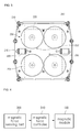
FIG. 3 is a plan view showing a second cleaning unit disposed on an outer surface of a window according to an embodiment of the present invention.FIG. 3 shows a structure of a lower face of thesecond cleaning unit 200, which makes contact with a window. - Referring to
FIG. 3 , thesecond cleaning unit 200 may include asecond frame 210, a plurality ofsecond wheel members 220 and a plurality of cleaningmodules 230. - The
second frame 210 forms a body of thesecond cleaning unit 200, and may have a shape corresponding to the shape of thefirs frame 110 of thefirst cleaning unit 100. For example, thesecond frame 210 may have a plate structure having a rectangular cross-section. - The plurality of
first wheel members 120 is formed at the lower face of thesecond frame 210, and capable of making thesecond cleaning unit 200 move along thefirst cleaning unit 100 by magnetic force. - According to an embodiment of the present invention, the
second wheel member 220 is not connected to a driving part such as a motor, unlike thefirst wheel member 120 installed at thefirst cleaning unit 100, but thesecond wheel member 220 is installed at the second frame through an axis in order that thesecond wheel member 220 may naturally rotate when thesecond cleaning unit 200 moves. - Therefore, when the
second cleaning unit 200 moves with thefirst cleaning unit 100 through the magnetic force, thesecond wheel member 220 may rotate to operate as a bearing. - In
FIG. 3 , thesecond wheel member 220 is formed to have, for example, a circular cylindrical shape. However, the shape of thesecond wheel member 220 is not limited to that. For example, thesecond wheel member 220 may have a globular shape such as a ball bearing. - The
cleaning module 230 is formed to be exposed under a lower portion of thesecond frame 210 to clean a side of a window, for example an outer surface of a window on which thesecond cleaning unit 200 is disposed. - As shown in
FIG. 3 , thecleaning module 230 may include a plurality of modules, for example, such as acleaning pad 231 and adetergent sprayer 232. - Meanwhile, each of four disc shapes included in the
cleaning module 230 may be formed to be rotatable by a driving part (not shown). Further, thecleaning module 230 may be formed to be protruded from a lower face of thesecond frame 210 by a specific distance, so that thecleaning module 230 can rotate to perform cleaning of the outer face of the window by frictional force when thesecond cleaning unit 200 is attached to the outer face of the window. - In order that the
cleaning module 230 easily remove dusts by frictional force when rotating, apad 231 including fabric, rubber, etc. may be attached to an exposed face of thecleaning module 230. In this case, in order to improve cleaning performance of the window cleaning apparatus, thepad 231 may be formed by a material of minute fabric or porosity. - Additionally, the
cleaning module 230 may include thedetergent sprayer 232 for spraying detergent. For example, thedetergent sprayer 232 may be connected to a detergent container (not shown) and a pump (not shown) in thesecond cleaning unit 200 through a flowing path to receive detergent. Therefore, thecleaning module 230 can perform cleaning with spraying detergent to the window by thedetergent sprayer 232 when cleaning the window. - Meanwhile, the second
magnetic module 233 is disposed inside of thecleaning module 230, that is, in thesecond cleaning unit 200. The secondmagnetic module 233 may have a shape corresponding to the firstmagnetic module 130 in thefirst cleaning unit 100, but the shape of the secondmagnetic module 233 is not limited to that. The first and secondmagnetic modules second cleaning units - The second
magnetic module 233 may include magnet such as permanent magnet or electromagnet, or metal. Therefore, the first andsecond cleaning units second cleaning units - Further, a continuous force is applied to the
cleaning module 230 in a direction toward the window by the magnetic force between the first and secondmagnetic modules cleaning module 230 rotates. - Referring to
FIG. 3 , thesecond cleaning unit 200 may further include a plurality ofsub cleaning modules 240 formed at corner part of thesecond cleaning unit 200. Thecleaning module 230 is formed at inside of thesecond frame 210 so that it is very hard to clean the border region of the window. Therefore, thesub cleaning modules 240 of the second cleaning unit can clean the border region such as a window frame of the window. - The
sub cleaning module 240 may include a roller member (not shown) that is rotatably installed, and a brush formed at outer circumference surface of the roller member. Therefore, thesub cleaning module 240 can rotate to remove dust of the window frame when thesecond cleaning unit 200 moves along the window frame. - Additionally, the
sub cleaning modules 240 may perform the same function as thebuffer member 140 in thefirst cleaning unit 100. That is, the sub cleaning modules can minimize impact when collided with a protrusion such as a window frame and sense impact. - In the above, the window cleaning apparatus has a structure for cleaning only one surface of a window (that is outer surface of a window) as described referring to
FIG. 1 through FIG. 3 , but the above is only an embodiment and the present invention is not limited to that. - For example, the
first cleaning unit 100 can also include acleaning module 230 in thesecond cleaning unit 200, so that the window cleaning apparatus can clean both surface of a window simultaneously. - According to the embodiment of the present invention, the magnetic force between the first and
second cleaning units - Referring to
FIG. 4 , a magneticforce sensing part 300 senses magnetic force or physical tension between the first andsecond cleaning units second cleaning units - The magnetic force between the first and
second cleaning units second cleaning units magnetic modules second cleaning units - Meanwhile, the
magnetic force controller 310 may control the magnetic force of themagnetic module 130 in order that the magnetic force that is sensed satisfies previously set value. - For example, as the magnetic force between the first and second
magnetic modules second cleaning units - On the contrary, as the magnetic force between the first and second
magnetic modules - Therefore, the previously set value of the magnetic force may be set considering the stability and mobility of the window cleaning apparatus as described above. In detail, the previously set value may be set in a range of a maximum value that allows the window cleaning apparatus to easily move and a minimum value that allows the window cleaning apparatus to stably attached to a window.
- Therefore, the
magnetic force controller 310 may adjust the magnetic force between the first and secondmagnetic modules second cleaning units force sensing part 300, is out of the previously set value range. -
FIG. 5 is a block diagram showing embodiments of first and second cleaning units installed in the window cleaning apparatus, and explanation regarding elements of the first andsecond cleaning units FIG. 1 through FIG. 4 will be omitted. - Referring to
FIG. 5 , thefirst cleaning unit 100 may include a firstmagnetic module 130, adisplay part 150, a firstwireless communication module 160, amain controller 103 and amagnetic force controller 310, and thesecond cleaning unit 200 may include a secondmagnetic module 233, a secondwireless communication module 260, amain controller 303, amagnetic sensor 301 or a physical tension sensor (not shown) and A/D converter 302. - At first, the
magnetic sensor 301 included in thesecond cleaning unit 200 senses the magnetic force between the first and secondmagnetic modules D converter 302. In order for that, themagnetic sensor 301 may be disposed adjacent to the secondmagnetic module 233. - The first
wireless communication module 160 included in thefirst cleaning unit 100 and the secondwireless communication module 260 included in thesecond cleaning unit 200 may receive and transmit signals through a short-range wireless telecommunication technology such as Bluetooth or Zigbee. - The second
wireless communication module 260 transmits the digitalized magnetic force to the firstwireless communication module 160 included in thefirst cleaning unit 100, so that thefirst cleaning unit 100 receives the magnetic force value that is sensed by thesecond cleaning unit 200. - The magnetic force value received by the first
wireless communication module 160 is inputted to themagnetic force controller 310, and themagnetic force controller 310 controls the firstmagnetic module 130 in accordance with the inputted magnetic force value to adjust the magnetic force between the first and secondmagnetic modules - In this case, the
magnetic force controller 310 may be formed in various forms, for example, a distance between the first and secondmagnetic modules magnetic modules magnetic modules magnetic force controller 310, and detailed explanation for this will be omitted. -
FIG. 6 is a flow chart showing a method of controlling an initialization of a magnetic force of the window cleaning apparatus according to an embodiment of the present invention, and the method shown inFIG. 6 is explained with a block diagram shown inFIGS. 4 and5 . - In an embodiment according to the present invention which will be described below, a
magnetic force controller 310 is included in afirst cleaning unit 100, magneticforce sensing part 300 is includes in asecond cleaning unit 200, thefirst cleaning unit 100 is operated after thesecond cleaning unit 200 is operated, and the first andsecond cleaning units second cleaning units - First, the
second cleaning unit 200 is operated, and then, magnetic force X is sensed on a side of the second cleaning unit 200 (Refer to S1 and S2). - Herein, magnetic force between the first and
second cleaning units magnetic units second cleaning units magnetic sensor 301 included in the magneticforce sensing part 300. - Of course, the magnetic
force sensing part 300 may be included at least one of the first andsecond cleaning units force sensing part 300 to be adjacent to at least one of the first andsecond cleaning units force sensing part 300 according to an embodiment of the present invention is explained in a condition that the magneticforce sensing part 300 is included in thesecond cleaning unit 200 which is attached to an outer side of the window. - However, the magnetic force measured by the magnetic
force sensing part 300, which is disposed inside thesecond cleaning unit 200, may be changed by an assembly state of the product, surface position of the rotated magnet, change of temperature, and latitude of the earth, etc., since the magnetic force is measured by mutual electromagnetic force. - Therefore, when the magnetic force measured by the magnetic
force sensing part 300 is changed, wireless communication between the first andsecond cleaning units - Therefore, it is necessary to maintain uniformly the magnetic force X measured by the magnetic
force sensing part 300, and to achieve this, it is necessary to initialize the measured magnetic force X. - Next, the measured magnetic force X is compared with a reference Xo and a previous set time t, and the measured magnetic force X is set as initial value X1 (Refer to S3, S4, and S6).
- In more detail, the measured magnetic force X is inputted to a
main controller 303 included in the magneticforce sensing part 300, and compared with a previous set reference Xo by themain controller 303. The reference Xo is determined considering an assembly state of the product, surface position of the rotated magnet, change of temperature, and latitude of the earth, etc. - Herein, when the measured magnetic force X satisfies the reference Xo, the measured magnetic force X is determined if it satisfies the reference Xo during the previous set time t to consider if there is another external magnetic force.
- Therefore, if the measured magnetic force X satisfies the reference Xo and maintains previous set time, and then, it is determined that there is no external magnetic force which affect the measured magnetic force X, and the measured magnetic force X is set as the initial value X1.
- On the other hand, if the measured magnetic force X does not satisfy the reference Xo, or it satisfies the reference Xo but does not maintains previous set time t, the
main controller 303 informs an error of magnetism (Refer to S5). - Herein the previous set time t is a stabilization time of measuring magnetic force, and is a time in which magnetic force between the first and
second cleaning units - Thus, if the measured magnetic force X does not satisfy the reference Xo, then, it is determined that magnetic force is affected by factors mentioned above. Also, if the measured magnetic force X does not maintain the reference Xo during the previous set time t, then, it is determined that the magnetic force is affected by object with magnetic force or object with metal material in the initial operation.
- Therefore, the measure magnetic force X measured by the magnetic
force sensing part 300 is determined to be difficult that it is truly measured from the first andsecond cleaning units - Then, the
first cleaning unit 100 is operated, magnetic force between the first andsecond cleaning units - In more detail, the first and
second cleaning units force sensing part 300 consistently measures magnetic force change between the first andsecond cleaning units second cleaning unit 200 to thefirst cleaning unit 100, is performed. - In one embodiment, data sent in the initialization operation may include battery state of the
second cleaning unit 200, bumper recognition state, driving pump state or control state of driving motor, magnetic force recognition state, etc. - Next, the initial value X1 is compared with an error range of the initial value(X1-x) during the transmission of the data between the first and
second cleaning units - Herein, the error range of the initial value(X1-x) is previously set, and means an error range measured by the magnetic
force sensing part 300 of thesecond cleaning unit 200 in which external effect is excluded. - If the first and
second cleaning units second cleaning units second cleaning units - However, if the initial value X1 is out of the error range of the initial value(X1-x), it means that the initialization operation is performed in a state that the first and
second cleaning units first cleaning unit 100 is separated from thesecond cleaning unit 200, and therefore, the process of comparing the measured magnetic force with the reference Xo and re-setting as the initial value X1 are repeated. -
FIG. 7 is a flow chart showing a method of controlling an initialization of wireless communication of window cleaning apparatus according to an embodiment of the present invention. - An embodiment according to the present invention which will be described below and includes first and second cleaning units cleaning a window in pair, is explained in a condition that one of the cleaning unit is breakdown and another first cleaning unit or second cleaning unit is added or multiple pairs of first and second cleaning units are used.
- First, first and
second cleaning units - The first and
second cleaning units second cleaning units second cleaning unit second cleaning units - In one embodiment, when first and
second cleaning units second cleaning units - Next, when a portion of the multiple pairs of the first and
second cleaning units - In an exemplary embodiment, when there are two pairs of cleaning units, first and
second cleaning units second cleaning units second cleaning units - Herein, when the first and
second cleaning units second cleaning units second cleaning units second cleaning units - Therefore, cleaning units based on pair which are may be operated together are searched by transmitting/receiving data through designated address.
- However, when the first and
second cleaning units second cleaning units - Herein, the
first cleaning unit 100 of the pair A and thesecond cleaning unit 200 of the pair B are turned on in neighboring position, then, they are not able to transmit/receive data through the designated address but through the public address. - Therefore, the first and
second cleaning units - Thus, an intensity of radio frequency signal between the first and
second cleaning units - Data transmission between the first and
second cleaning units second cleaning units - Thus, data transmission is available in which the intensity of radio frequency is set as maximum as possible based on a reference value of wireless authentication, but, the intensity of radio frequency may be properly adjusted since it may causer power consumption during the data transmission.
- Therefore, the reference values which is compared with the intensity of radio frequency signal may be set lower than the maximum reference value of wireless authentication but higher than a minimum value in which data loss is not occurred, the reference value may be set in a range in which a radio frequency signal may reach 3-4 meters, and, power consumption is reduced, as well as, data loss is prevented.
- Herein, when the intensity of radio frequency signal of the first and
second cleaning units - On the other hand, when the intensity of radio frequency signal of the first and
second cleaning units second cleaning units
Claims (12)
- A method of controlling a window cleaning apparatus including first and second cleaning units attached to a window comprising:operating at least one cleaning unit among the first and second cleaning units;measuring a magnetic force X between first and second magnetic modules installed on each of the first and second cleaning units;comparing the measured magnetic force X with a reference value Xo; andsetting the measured magnetic force X for an initial value X1 or informing of an error of a magnetism according to a result of the comparison.
- A method of claim 1, wherein comparing the measured magnetic force with a reference value Xo comprises:comparing the measured magnetic force X with the reference value Xo; andcomparing the measured magnetic force X with the reference value Xo during a previous set time t.
- A method claim of 2, wherein the measured magnetic force X is set for an initial value X1 when the measured magnetic force X satisfies the reference value Xo and the measured magnetic force X satisfies the reference value Xo during the previous set time t.
- The method of claim 2, wherein the error is alarmed when the measured magnetic force does not satisfy the reference value Xo.
- The method of claim 2, wherein the error is alarmed when the measured magnetic force X does not satisfy the reference value Xo during the previous set time t.
- The method of any one of claims 1 to 5, further comprising:measuring a change of the measured magnetic force between the first and second cleaning units after setting the initial value X1; andtransmitting data between the first and second cleaning units after operating the first and second cleaning units.
- The method of claim 6, further comprising:comparing the initial value X1 with an error range X1-x,;comparing the changed magnetic force with the initial value X1 and re-setting the changed magnetic force for the initial value X1 according to a result of a comparison; orinforming of an error of a magnetism.
- A method of controlling a window cleaning apparatus including at least one or more first cleaning unit and at least one or more second cleaning unit attached to both sides of a window and moved by a magnetic force comprising:registering the first and second cleaning units to each other in advance to be capable of communicating with each other;searching first and second cleaning units which are registered on an initial operation;measuring an intensity of a radio frequency signal between the searched first and second cleaning units;setting the searched first and second cleaning units for an available pair according to the measured intensity of the radio frequency signal.
- The method of claim 8, wherein registering the first and second cleaning units comprises registering a designated address and a public address which enables transmitting data between the first and second cleaning units.
- The method of claim 9, wherein searching first and second cleaning units comprises:searching first and second cleaning units which are capable of transmitting data through the designated address; andsearching first and second cleaning units which are capable of transmitting data through the public address.
- The method of claim 8, wherein setting the searched first and second cleaning units for an available pair comprises:setting the searched first and second cleaning units for an available pair when the intensity of the radio frequency satisfies a reference value; andadjusting the intensity of the radio frequency between the searched first and second cleaning units when the intensity of the radio frequency does not satisfy the reference value.
- The method of claim 11, wherein the reference value is a range in which the radio frequency signal reaches 3-4 meters.
Applications Claiming Priority (3)
| Application Number | Priority Date | Filing Date | Title |
|---|---|---|---|
| US201261650500P | 2012-05-23 | 2012-05-23 | |
| US201261650499P | 2012-05-23 | 2012-05-23 | |
| PCT/KR2012/005766 WO2013176335A1 (en) | 2012-05-23 | 2012-07-19 | Method for controlling window cleaning apparatus |
Publications (2)
| Publication Number | Publication Date |
|---|---|
| EP2853185A1 true EP2853185A1 (en) | 2015-04-01 |
| EP2853185A4 EP2853185A4 (en) | 2016-03-09 |
Family
ID=49623998
Family Applications (1)
| Application Number | Title | Priority Date | Filing Date |
|---|---|---|---|
| EP12877238.1A Withdrawn EP2853185A4 (en) | 2012-05-23 | 2012-07-19 | METHOD FOR CONTROLLING A WINDOW CLEANING APPARATUS |
Country Status (4)
| Country | Link |
|---|---|
| EP (1) | EP2853185A4 (en) |
| JP (1) | JP2015531609A (en) |
| KR (1) | KR101617991B1 (en) |
| WO (1) | WO2013176335A1 (en) |
Family Cites Families (11)
| Publication number | Priority date | Publication date | Assignee | Title |
|---|---|---|---|---|
| DE3630324A1 (en) * | 1986-09-05 | 1988-03-10 | Langenfeld Bernd Artur | Electric pane-cleaning apparatus |
| JP2003284169A (en) * | 2002-03-20 | 2003-10-03 | Mitsubishi Electric Corp | Remote control device for home appliances |
| JP4659480B2 (en) * | 2005-02-15 | 2011-03-30 | キヤノン株式会社 | Wireless communication apparatus, wireless communication, program, and storage medium |
| KR100963247B1 (en) * | 2008-02-26 | 2010-06-17 | 고광욱 | Auto double glazing cleaner |
| JP5279739B2 (en) * | 2010-01-29 | 2013-09-04 | 本田技研工業株式会社 | Wireless communication system |
| KR20110096942A (en) * | 2010-02-24 | 2011-08-31 | 주식회사 에스 피 씨 | Window cleaner |
| WO2011126193A1 (en) * | 2010-04-09 | 2011-10-13 | 주식회사 일심글로발 | Glass window cleaning device and a control method therefor |
| KR101071667B1 (en) * | 2010-04-09 | 2011-10-11 | 주식회사 일심글로발 | Window cleaning apparatus and its control method |
| US8783991B2 (en) * | 2010-06-19 | 2014-07-22 | Jamé TRUDEAU | Magnetic cleaning tool with fluid pump |
| KR101212374B1 (en) * | 2010-07-06 | 2012-12-13 | 엘지전자 주식회사 | An auto cleaner |
| CN102327093A (en) * | 2010-12-30 | 2012-01-25 | 刘忠臣 | Safe magnetic glass wiping device |
-
2012
- 2012-07-19 KR KR1020147034102A patent/KR101617991B1/en not_active Expired - Fee Related
- 2012-07-19 WO PCT/KR2012/005766 patent/WO2013176335A1/en not_active Ceased
- 2012-07-19 EP EP12877238.1A patent/EP2853185A4/en not_active Withdrawn
- 2012-07-19 JP JP2015513872A patent/JP2015531609A/en active Pending
Also Published As
| Publication number | Publication date |
|---|---|
| WO2013176335A1 (en) | 2013-11-28 |
| KR101617991B1 (en) | 2016-05-04 |
| KR20150018538A (en) | 2015-02-23 |
| EP2853185A4 (en) | 2016-03-09 |
| JP2015531609A (en) | 2015-11-05 |
Similar Documents
| Publication | Publication Date | Title |
|---|---|---|
| JP5706961B2 (en) | Glass window cleaning equipment | |
| US10028629B2 (en) | Window cleaning apparatus and method of controlling the same | |
| KR101311375B1 (en) | Window cleaning apparatus and method for control the apparatus | |
| KR101649665B1 (en) | Moving robot and controlling method thereof | |
| EP3712519B1 (en) | Air purifying system and method for controlling the air purifying system | |
| CN109124489A (en) | System at least two cleaning equipments | |
| CN102048499B (en) | Mobile robot system and control method thereof | |
| AU2020210293B2 (en) | Robot cleaner and robot system having the same | |
| US20130060380A1 (en) | Apparatus for cleaning a glass window and method for controlling the movement thereof | |
| TW201810195A (en) | Method for operating an independently moving surface treatment device | |
| KR100743467B1 (en) | Auto windshield cleaner | |
| EP2572617B1 (en) | Window-cleaning apparatus, and method for controlling the movement thereof | |
| CN102591338B (en) | Control system of glass-cleaning robot, and control method thereof | |
| KR102615032B1 (en) | User device, cleaning robot including the same, and controlling method thereof | |
| KR102505395B1 (en) | Air cleaning robot method for driving the same | |
| WO2023051485A1 (en) | Traveling wheel, autonomous operation apparatus, and method for detecting state of traveling wheel | |
| KR102057325B1 (en) | Robot scavenger apparatus for cleaning window | |
| KR20110097123A (en) | vacuum cleaner | |
| KR101071667B1 (en) | Window cleaning apparatus and its control method | |
| JP2015531609A (en) | Control method of window glass cleaning device | |
| JP7518390B2 (en) | System and method for detecting magnetic markers | |
| CN206166821U (en) | Glass window cleans machine people and glass window cleaning system | |
| KR101223347B1 (en) | Controlling method of an auto cleaner | |
| CN120345212A (en) | Cleaning machine, control method of cleaning machine, cleaning system and control method of cleaning system | |
| KR20130133999A (en) | Window cleaning apparatus and method for control magnetic force of the apparatus |
Legal Events
| Date | Code | Title | Description |
|---|---|---|---|
| PUAI | Public reference made under article 153(3) epc to a published international application that has entered the european phase |
Free format text: ORIGINAL CODE: 0009012 |
|
| 17P | Request for examination filed |
Effective date: 20141222 |
|
| AK | Designated contracting states |
Kind code of ref document: A1 Designated state(s): AL AT BE BG CH CY CZ DE DK EE ES FI FR GB GR HR HU IE IS IT LI LT LU LV MC MK MT NL NO PL PT RO RS SE SI SK SM TR |
|
| AX | Request for extension of the european patent |
Extension state: BA ME |
|
| DAX | Request for extension of the european patent (deleted) | ||
| RA4 | Supplementary search report drawn up and despatched (corrected) |
Effective date: 20160205 |
|
| RIC1 | Information provided on ipc code assigned before grant |
Ipc: A47L 1/03 20060101AFI20160201BHEP |
|
| STAA | Information on the status of an ep patent application or granted ep patent |
Free format text: STATUS: THE APPLICATION IS DEEMED TO BE WITHDRAWN |
|
| 18D | Application deemed to be withdrawn |
Effective date: 20160906 |