EP2853183A1 - Heating seat of kettle - Google Patents
Heating seat of kettle Download PDFInfo
- Publication number
- EP2853183A1 EP2853183A1 EP13793767.8A EP13793767A EP2853183A1 EP 2853183 A1 EP2853183 A1 EP 2853183A1 EP 13793767 A EP13793767 A EP 13793767A EP 2853183 A1 EP2853183 A1 EP 2853183A1
- Authority
- EP
- European Patent Office
- Prior art keywords
- kettle
- rack
- enclosure
- heating device
- posts
- Prior art date
- Legal status (The legal status is an assumption and is not a legal conclusion. Google has not performed a legal analysis and makes no representation as to the accuracy of the status listed.)
- Granted
Links
- 238000010438 heat treatment Methods 0.000 title claims abstract description 46
- 238000009434 installation Methods 0.000 claims description 17
- 229920001296 polysiloxane Polymers 0.000 claims description 4
- VTLYHLREPCPDKX-UHFFFAOYSA-N 1,2-dichloro-3-(2,3-dichlorophenyl)benzene Chemical compound ClC1=CC=CC(C=2C(=C(Cl)C=CC=2)Cl)=C1Cl VTLYHLREPCPDKX-UHFFFAOYSA-N 0.000 description 7
- 238000005265 energy consumption Methods 0.000 description 4
- 238000009413 insulation Methods 0.000 description 4
- XLYOFNOQVPJJNP-UHFFFAOYSA-N water Substances O XLYOFNOQVPJJNP-UHFFFAOYSA-N 0.000 description 4
- 239000007788 liquid Substances 0.000 description 2
- UCLKLGIYGBLTSM-UHFFFAOYSA-N 1,2,3,4-tetrachloro-5-(2,5-dichlorophenyl)benzene Chemical compound ClC1=CC=C(Cl)C(C=2C(=C(Cl)C(Cl)=C(Cl)C=2)Cl)=C1 UCLKLGIYGBLTSM-UHFFFAOYSA-N 0.000 description 1
- 206010053615 Thermal burn Diseases 0.000 description 1
- 230000007812 deficiency Effects 0.000 description 1
- 230000002349 favourable effect Effects 0.000 description 1
- 239000011521 glass Substances 0.000 description 1
- 230000004048 modification Effects 0.000 description 1
- 238000012986 modification Methods 0.000 description 1
- 229910001220 stainless steel Inorganic materials 0.000 description 1
- 239000010935 stainless steel Substances 0.000 description 1
Images


Classifications
-
- A—HUMAN NECESSITIES
- A47—FURNITURE; DOMESTIC ARTICLES OR APPLIANCES; COFFEE MILLS; SPICE MILLS; SUCTION CLEANERS IN GENERAL
- A47J—KITCHEN EQUIPMENT; COFFEE MILLS; SPICE MILLS; APPARATUS FOR MAKING BEVERAGES
- A47J27/00—Cooking-vessels
- A47J27/21—Water-boiling vessels, e.g. kettles
- A47J27/21008—Water-boiling vessels, e.g. kettles electrically heated
- A47J27/21041—Water-boiling vessels, e.g. kettles electrically heated with heating elements arranged outside the water vessel
-
- A—HUMAN NECESSITIES
- A47—FURNITURE; DOMESTIC ARTICLES OR APPLIANCES; COFFEE MILLS; SPICE MILLS; SUCTION CLEANERS IN GENERAL
- A47J—KITCHEN EQUIPMENT; COFFEE MILLS; SPICE MILLS; APPARATUS FOR MAKING BEVERAGES
- A47J36/00—Parts, details or accessories of cooking-vessels
- A47J36/24—Warming devices
- A47J36/2483—Warming devices with electrical heating means
-
- A—HUMAN NECESSITIES
- A47—FURNITURE; DOMESTIC ARTICLES OR APPLIANCES; COFFEE MILLS; SPICE MILLS; SUCTION CLEANERS IN GENERAL
- A47J—KITCHEN EQUIPMENT; COFFEE MILLS; SPICE MILLS; APPARATUS FOR MAKING BEVERAGES
- A47J27/00—Cooking-vessels
- A47J27/21—Water-boiling vessels, e.g. kettles
- A47J27/21008—Water-boiling vessels, e.g. kettles electrically heated
- A47J27/2105—Water-boiling vessels, e.g. kettles electrically heated of the cordless type, i.e. whereby the water vessel can be plugged into an electrically-powered base element
-
- A—HUMAN NECESSITIES
- A47—FURNITURE; DOMESTIC ARTICLES OR APPLIANCES; COFFEE MILLS; SPICE MILLS; SUCTION CLEANERS IN GENERAL
- A47J—KITCHEN EQUIPMENT; COFFEE MILLS; SPICE MILLS; APPARATUS FOR MAKING BEVERAGES
- A47J27/00—Cooking-vessels
- A47J27/21—Water-boiling vessels, e.g. kettles
- A47J27/21166—Constructional details or accessories
Definitions
- the present invention relates to a heating device, and more especially to a kettle heating device.
- the heating base for electric kettles available on the market currently is simple and is undesirable in the following aspects:
- the present invention aims at providing a heating device for a kettle featuring high security, desirable thermal insulation, low energy consumption, and capability of avoiding left-right movement of the kettle and preventing slipping of the kettle.
- a middle-through connection post is centered in the rack, the wire coil is provided with a connection hole fit for the connection post and sheathed into the connection post via the connection hole.
- the temperature sensor sheathed with a spring which is in the through hole of the connection post passes through the connection post, and a baffle obstructing the spring is arranged in the through hole of the connection post.
- the periphery in the upper part of the rack extends upwards to form several first installation posts with holes
- the bottom of the heating platform extends downwards to form several positioning posts corresponding to the first installation posts one by one, wherein the positioning posts are inserted into the holes of the corresponding first installation posts.
- the periphery in the lower part of the rack extends downwards to form several fastening posts, and the bottom of the enclosure extends upwards to form several second installation posts with holes corresponding to the fastening posts one by one, wherein the fastening posts are inserted into the holes of the corresponding second installation posts.
- the lower part of the rack extends downwards to form several connection rods, and correspondingly, the core PCB is provided with several hollow holes corresponding to the connection rods one by one, wherein the connection rods are inserted into the hollow holes.
- the enclosure is provided with a control button which is connected with the core PCB through button PCB.
- a temperature fuse cover is further included, wherein a fuse connecting the core PCB and external power is mounted inside the temperature fuse cover installed at the bottom of the heating platform and exposed from the bottom of the housing cavity.
- silicone cushions for supporting the kettle are configured at the bottom of the housing cavity.
- the heating device for a kettle has the following favourable effects: by providing a heating platform with a housing cavity arranged on the enclosure, when in use, the kettle is placed in the housing cavity and fixed by means of the wall part of the housing cavity, thus avoiding left and right movement of the kettle on the heating platform, preventing the slipping of the kettle, offering thermal insulation function for the kettle and reducing energy consumption; moreover, the wall part of the housing cavity can also prevent the user from accidental contact of the heated wall, in this way to putting an end to accidental scalding and greatly improving safety; furthermore, the heating device of the present invention not only can heat water, but also other liquids.
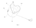
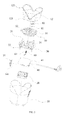
- FIGs. 1 ⁇ 4 show the structure of a preferred embodiment of the present invention.
- a heating device for a kettle comprising an enclosure 10, a radiator fan 20, a rack 30, a core PCB 40, a wire coil 50, and a temperature sensor 60 in the enclosure 10, wherein:
- the radiator fan 20 is mounted at the bottom of the enclosure 10 to dissipate heat of the core PCB 40.
- the rack 30 is fixed inside the enclosure 10, the periphery in the upper part of the rack 30 extends upwards to form several first installation posts 31 with holes, and the bottom of the heating platform 12 extends downwards to form several positioning posts 123 corresponding to the first installation posts 31 one by one, wherein the positioning posts 123 are inserted into the holes of the corresponding first installation posts 31; the periphery in the lower part of the rack 30 extends downwards to form several fastening posts 32, and the bottom of the enclosure 10 extends upwards to form several second installation posts 13 with holes corresponding to the fastening posts 32 one by one, wherein the fastening posts 32 are inserted into the holes of the corresponding second installation posts 13; moreover, the lower part of the rack 30 extends downwards to form several connection rods 33, and correspondingly, the core PCB 40 is provided with several hollow holes 41 corresponding to the connection rods 33 one by one, wherein the core PCB 40 which is configured in the lower part of the rack 30 and above the radiator fan 20 is inserted into the corresponding hollow
- the wire coil 50 which is provided with a heat coil 51 is installed on the rack 30, the temperature senor 60 which is electrically connected with the core PCB 40 extends into the housing cavity 121 of the heating platform 12 after passing through the rack 30 and the wire coil 50 in turn upwards.
- a middle-through connection post 34 is centered in the rack 30, the wire coil 50 is provided with a connection hole 52 fit for the connection post 34 and sheathed into the connection post 34 via the connection hole 52, the temperature sensor 60 sheathed with a spring 61 which is in the through hole of the connection post 34 passes through the connection post 34, and a baffle obstructing the spring 61 is arranged in the through hole of the connection post 34.
- the enclosure 10 is provided with a control button 14 which is connected with the core PCB 40 through button PCB 141.
- the heating device can be conveniently controlled by means of the control button 14.
- a temperature fuse cover 80 is further included in the heating device, wherein a fuse 81 connecting the core PCB 40 and external power is mounted inside the temperature fuse cover 80 installed at the bottom of the heating platform 12 and exposed from the underside of the housing cavity 121.
- the kettle 70 made of glass or stainless steel, filled with water or other liquid, is placed in the housing cavity 121 of the heating platform 12, the wall part of the housing cavity 121 fixes the kettle 70 to avoid left and right movement of the kettle 70 on the heating platform 12, prevent the slipping of the kettle 70 and offer thermal insulation function for the kettle 70, thus reducing energy consumption.
- the wall part of the housing cavity 121 can also prevent the user from accidental contact of the heated wall, in this way to put an end of accidental scald and greatly improve safety.
Landscapes
- Engineering & Computer Science (AREA)
- Food Science & Technology (AREA)
- Cookers (AREA)
Abstract
Description
- The present invention relates to a heating device, and more especially to a kettle heating device.
- The heating base for electric kettles available on the market currently is simple and is undesirable in the following aspects:
- 1. the water heated in the kettle placed on the heating base transfers heat to the wall of the kettle, and the user is prone to be scalded due to accidental contact of the wall, so the security is low;
- 2. the heating base is not provided with a thermal insulation device, so the hot water in the kettle may become cool soon after heating and re-heating is required after a short period, thus the energy consumption is high;
- 3. The kettle is prone to move on the heating base left and right, and even slip from the heating base.
- To address the deficiencies in the prior art, the present invention aims at providing a heating device for a kettle featuring high security, desirable thermal insulation, low energy consumption, and capability of avoiding left-right movement of the kettle and preventing slipping of the kettle.
- To realize the objective of the present invention, the following technical solution is adopted:
- a heating device for a kettle, comprising an enclosure, a radiator fan, a rack, a core PCB, a wire coil, and a temperature sensor in the enclosure, wherein a heating platform which has a housing cavity for accommodating the kettle is arranged on the upper part of the enclosure, the radiator fan is mounted at the bottom of the enclosure, the rack is fixed inside the enclosure, the core PCB is configured in the lower part of the rack and above the radiator fan, the wire coil which is provided with a heat coil is installed on the rack, the temperature senor which is electrically connected with the core PCB extends into the housing cavity of the heating platform after passing through the rack, and thewire coil in turn upwards.
- Preferably, a middle-through connection post is centered in the rack, the wire coil is provided with a connection hole fit for the connection post and sheathed into the connection post via the connection hole.
- Preferably, the temperature sensor sheathed with a spring which is in the through hole of the connection post passes through the connection post, and a baffle obstructing the spring is arranged in the through hole of the connection post.
- Preferably, the periphery in the upper part of the rack extends upwards to form several first installation posts with holes, and the bottom of the heating platform extends downwards to form several positioning posts corresponding to the first installation posts one by one, wherein the positioning posts are inserted into the holes of the corresponding first installation posts.
- Preferably, the periphery in the lower part of the rack extends downwards to form several fastening posts, and the bottom of the enclosure extends upwards to form several second installation posts with holes corresponding to the fastening posts one by one, wherein the fastening posts are inserted into the holes of the corresponding second installation posts.
- Preferably, the lower part of the rack extends downwards to form several connection rods, and correspondingly, the core PCB is provided with several hollow holes corresponding to the connection rods one by one, wherein the connection rods are inserted into the hollow holes.
- Preferably, the enclosure is provided with a control button which is connected with the core PCB through button PCB.
- Preferably, a temperature fuse cover is further included, wherein a fuse connecting the core PCB and external power is mounted inside the temperature fuse cover installed at the bottom of the heating platform and exposed from the bottom of the housing cavity.
- Preferably, several silicone cushions for supporting the kettle are configured at the bottom of the housing cavity.
- Preferably, several rubber cushions are configured at the bottom of the enclosure.
- The heating device for a kettle according to the present invention has the following favourable effects: by providing a heating platform with a housing cavity arranged on the enclosure, when in use, the kettle is placed in the housing cavity and fixed by means of the wall part of the housing cavity, thus avoiding left and right movement of the kettle on the heating platform, preventing the slipping of the kettle, offering thermal insulation function for the kettle and reducing energy consumption; moreover, the wall part of the housing cavity can also prevent the user from accidental contact of the heated wall, in this way to putting an end to accidental scalding and greatly improving safety; furthermore, the heating device of the present invention not only can heat water, but also other liquids.
-
-
FIG. 1 is a structural view of the embodiment of the present invention; -
FIG. 2 is an exploded view of the embodiment of the present invention; -
FIG. 3 is a structural view of the enclosure in the embodiment of the present invention; -
FIG. 4 is a structural view of the rack in the embodiment of the present invention; -
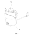
FIG. 5 is a view of the using states of embodiment of the present invention. -
- 10.
enclosure 11. rubber cushion; 12. heating platform; 121. housing cavity; 122. silicone cushion; 123. positioning post; 13. second installation post; 14. control button; 141. button PCB; - 20. radiator fan;
- 30. rack; 31. first installation post; 32. fastening post; 33. connection rod; 34. connection post;
- 40. core PCB; 41. hollow hole;
- 50. wire coil; 51. heat coil; 52. connection hole;
- 60. temperature sensor; 61. spring;
- 70. kettle;
- 80. temperature fuse cover; 81. temperature fuse.
- The present inventionwill be further detailed hereinafter in conjunction with the embodiments and accompanying drawings.
-
FIGs. 1∼4 show the structure of a preferred embodiment of the present invention. A heating device for a kettle, comprising anenclosure 10, aradiator fan 20, arack 30, acore PCB 40, awire coil 50, and atemperature sensor 60 in theenclosure 10, wherein: - Several rubber cushions 11 are configured at the bottom of the
enclosure 10, aheating platform 12 which has ahousing cavity 121 for accommodating thekettle 70 is arranged on the upper part of theenclosure 10,several silicone cushions 121 for supporting thekettle 70 are configured at the bottom of thehousing cavity 121. - The
radiator fan 20 is mounted at the bottom of theenclosure 10 to dissipate heat of thecore PCB 40. - The
rack 30 is fixed inside theenclosure 10, the periphery in the upper part of therack 30 extends upwards to form several first installation posts 31 with holes, and the bottom of theheating platform 12 extends downwards to formseveral positioning posts 123 corresponding to the first installation posts 31 one by one, wherein the positioning posts 123 are inserted into the holes of the corresponding first installation posts 31; the periphery in the lower part of therack 30 extends downwards to formseveral fastening posts 32, and the bottom of theenclosure 10 extends upwards to form several second installation posts 13 with holes corresponding to the fastening posts 32 one by one, wherein the fastening posts 32 are inserted into the holes of the corresponding second installation posts 13; moreover, the lower part of therack 30 extends downwards to formseveral connection rods 33, and correspondingly, thecore PCB 40 is provided with severalhollow holes 41 corresponding to theconnection rods 33 one by one, wherein thecore PCB 40 which is configured in the lower part of therack 30 and above theradiator fan 20 is inserted into the correspondinghollow holes 41 via theconnection rods 33. - The
wire coil 50 which is provided with aheat coil 51 is installed on therack 30, thetemperature senor 60 which is electrically connected with thecore PCB 40 extends into thehousing cavity 121 of theheating platform 12 after passing through therack 30 and thewire coil 50 in turn upwards. Specifically, a middle-throughconnection post 34 is centered in therack 30, thewire coil 50 is provided with aconnection hole 52 fit for theconnection post 34 and sheathed into theconnection post 34 via theconnection hole 52, thetemperature sensor 60 sheathed with aspring 61 which is in the through hole of theconnection post 34 passes through theconnection post 34, and a baffle obstructing thespring 61 is arranged in the through hole of theconnection post 34. - The
enclosure 10 is provided with acontrol button 14 which is connected with thecore PCB 40 throughbutton PCB 141. When in use, the heating device can be conveniently controlled by means of thecontrol button 14. - To increase security, a
temperature fuse cover 80 is further included in the heating device, wherein afuse 81 connecting thecore PCB 40 and external power is mounted inside the temperature fuse cover 80 installed at the bottom of theheating platform 12 and exposed from the underside of thehousing cavity 121. - As shown in
FIG. 5 , when in use, thekettle 70 made of glass or stainless steel, filled with water or other liquid, is placed in thehousing cavity 121 of theheating platform 12, the wall part of thehousing cavity 121 fixes thekettle 70 to avoid left and right movement of thekettle 70 on theheating platform 12, prevent the slipping of thekettle 70 and offer thermal insulation function for thekettle 70, thus reducing energy consumption. Moreover, the wall part of thehousing cavity 121 can also prevent the user from accidental contact of the heated wall, in this way to put an end of accidental scald and greatly improve safety. - The description above is only the preferred embodiment of the present invention other than the limitation to technical scope of the invention in any form. Any slight modification, equivalent change or improvement to the embodiment above based on the technical essence of the present invention is considered within the protection range of the technical solution of the present invention.
Claims (10)
- A heating device for a kettle, characterized in that it comprises an enclosure, a radiator fan, a rack, a core PCB, a wire coil, and a temperature sensor in the enclosure, wherein a heating platform which has a housing cavity for accommodating the kettle is arranged on the upper part of the enclosure, the radiator fan is mounted at the bottom of the enclosure, the rack is fixed inside the enclosure, the core PCB is configured in the lower part of the rack and above the radiator fan, the wire coil which is provided with a heat coil is installed on the rack, the temperature senor which is electrically connected with the core PCB extends into the housing cavity of the heating platform after passing through the rack, and the wire coil in turn upwards.
- The heating device for a kettle as claimed in Claim 1, characterized in that a middle-through connection post is centered in the rack, the wire coil is provided with a connection hole fit for the connection post and sheathed into the connection post via the connection hole.
- The heating device for a kettle as claimed in Claim 2, characterized in that the temperature sensor sheathed with a spring which is in the through hole of the connection post and passes through the connection post, and a baffle obstructing the spring is arranged in the through hole of the connection post.
- The heating device for a kettle as claimed in Claim 1, characterized in that the periphery in the upper part of the rack extends upwards to form several first installation posts with holes, and the bottom of the heating platform extends downwards to form several positioning posts corresponding to the first installation posts one by one, wherein the positioning posts are inserted into the holes of the corresponding first installation posts.
- The heating device for a kettle as claimed in Claim 1, characterized in that the periphery in the lower part of the rack extends downwards to form several fastening posts, and the bottom of the enclosure extends upwards to form several second installation posts with holes corresponding to the fastening posts one by one, wherein the fastening posts are inserted into the holes of the corresponding second installation posts.
- The heating device for a kettle as claimed in Claim 1, characterized in that the lower part of the rack extends downwards to form several connection rods, and correspondingly, the core PCB is provided with several hollow holes corresponding to the connection rods one by one, wherein the connection rods are inserted into the hollow holes.
- The heating device for a kettle as claimed in Claim 1, characterized in that the enclosure is provided with a control button which is connected with the core PCB through button PCB.
- The heating device for a kettle as claimed in Claim 1, characterized in that a temperature fuse cover is further included, wherein a fuse connecting the core PCB and external power is mounted inside the temperature fuse cover installed at the bottom of the heating platform and exposed from the bottom of the housing cavity.
- The heating device for a kettle as claimed in Claim 1, characterized in that several silicone cushions for supporting the kettle are configured at the bottom of the housing cavity.
- The heating device for a kettle as claimed in Claim 1, characterized in that several rubber cushions are configured at the bottom of the enclosure.
Applications Claiming Priority (2)
| Application Number | Priority Date | Filing Date | Title |
|---|---|---|---|
| CN2012202375287U CN202567831U (en) | 2012-05-23 | 2012-05-23 | Heating seat of cooking kettle |
| PCT/CN2013/071289 WO2013174160A1 (en) | 2012-05-23 | 2013-02-01 | Heating seat of kettle |
Publications (3)
| Publication Number | Publication Date |
|---|---|
| EP2853183A1 true EP2853183A1 (en) | 2015-04-01 |
| EP2853183A4 EP2853183A4 (en) | 2016-03-02 |
| EP2853183B1 EP2853183B1 (en) | 2021-06-02 |
Family
ID=47237300
Family Applications (1)
| Application Number | Title | Priority Date | Filing Date |
|---|---|---|---|
| EP13793767.8A Active EP2853183B1 (en) | 2012-05-23 | 2013-02-01 | Heating seat of kettle |
Country Status (4)
| Country | Link |
|---|---|
| US (1) | US9706871B2 (en) |
| EP (1) | EP2853183B1 (en) |
| CN (1) | CN202567831U (en) |
| WO (1) | WO2013174160A1 (en) |
Cited By (1)
| Publication number | Priority date | Publication date | Assignee | Title |
|---|---|---|---|---|
| EP3391790A4 (en) * | 2015-12-17 | 2019-07-10 | Haenim Co., Ltd. | Electric pot provided with infrared temperature sensor |
Families Citing this family (20)
| Publication number | Priority date | Publication date | Assignee | Title |
|---|---|---|---|---|
| CN202567831U (en) * | 2012-05-23 | 2012-12-05 | 广州思酷产品设计有限公司 | Heating seat of cooking kettle |
| CN105982535A (en) * | 2015-01-28 | 2016-10-05 | 广东美的生活电器制造有限公司 | Cordless liquid heating device |
| CN110169717A (en) | 2017-08-09 | 2019-08-27 | 沙克忍者运营有限责任公司 | Cooking system |
| USD914447S1 (en) | 2018-06-19 | 2021-03-30 | Sharkninja Operating Llc | Air diffuser |
| USD883014S1 (en) | 2018-08-09 | 2020-05-05 | Sharkninja Operating Llc | Food preparation device |
| USD903413S1 (en) | 2018-08-09 | 2020-12-01 | Sharkninja Operating Llc | Cooking basket |
| USD934027S1 (en) | 2018-08-09 | 2021-10-26 | Sharkninja Operating Llc | Reversible cooking rack |
| USD883015S1 (en) | 2018-08-09 | 2020-05-05 | Sharkninja Operating Llc | Food preparation device and parts thereof |
| KR20200112325A (en) | 2019-03-21 | 2020-10-05 | 엘지전자 주식회사 | electric kettle |
| KR20200112328A (en) | 2019-03-21 | 2020-10-05 | 엘지전자 주식회사 | electric kettle |
| EP3931493A1 (en) | 2019-02-25 | 2022-01-05 | SharkNinja Operating LLC | Cooking system with guard |
| US20190254476A1 (en) | 2019-02-25 | 2019-08-22 | Sharkninja Operating Llc | Cooking device and components thereof |
| KR20200112327A (en) | 2019-03-21 | 2020-10-05 | 엘지전자 주식회사 | electric kettle |
| KR20200112319A (en) | 2019-03-21 | 2020-10-05 | 엘지전자 주식회사 | electric kettle |
| KR20200112321A (en) * | 2019-03-21 | 2020-10-05 | 엘지전자 주식회사 | electric kettle |
| KR20200112322A (en) | 2019-03-21 | 2020-10-05 | 엘지전자 주식회사 | electric kettle |
| KR20200112320A (en) | 2019-03-21 | 2020-10-05 | 엘지전자 주식회사 | electric kettle |
| USD982375S1 (en) | 2019-06-06 | 2023-04-04 | Sharkninja Operating Llc | Food preparation device |
| USD918654S1 (en) | 2019-06-06 | 2021-05-11 | Sharkninja Operating Llc | Grill plate |
| US11678765B2 (en) | 2020-03-30 | 2023-06-20 | Sharkninja Operating Llc | Cooking device and components thereof |
Family Cites Families (15)
| Publication number | Priority date | Publication date | Assignee | Title |
|---|---|---|---|---|
| US3780794A (en) * | 1971-12-02 | 1973-12-25 | B Staub | Food table |
| US3962962A (en) * | 1974-10-03 | 1976-06-15 | Anderson William G | System and hot cabinet server |
| EP0026756A1 (en) | 1979-10-02 | 1981-04-08 | Franz Sterner | Storage container for hot drinks and heating device therefor |
| US5201797A (en) * | 1991-10-31 | 1993-04-13 | Weng Shun Te | Induction heater having cylindrical cooking receptacle |
| ES2128227B1 (en) * | 1996-01-18 | 1999-12-01 | Recio Angel Eloy Cuadrado | PACKAGE COOLER-HEATER. |
| US5842353A (en) * | 1996-12-13 | 1998-12-01 | Kuo-Liang; Lin | Apparatus for heating or cooling drinks |
| GB2403129B (en) * | 2001-04-11 | 2005-02-23 | Jeremy Thomas Vernon Pickering | Preparing hot drinks in a vehicle |
| US6403928B1 (en) * | 2001-05-18 | 2002-06-11 | Tracy L. Ford | Beverage heating assembly |
| TW580892U (en) * | 2002-11-25 | 2004-03-21 | Jiun-Guang Luo | Thermos cup |
| TW200518739A (en) * | 2003-10-07 | 2005-06-16 | Combi Corp | Apparatus for heating baby formula pot and method of operating the same |
| CN201234884Y (en) | 2008-07-21 | 2009-05-13 | 上海市杨浦区齐齐哈尔路第一小学 | Temperature control electric heating kettle |
| CN201879505U (en) | 2010-11-22 | 2011-06-29 | 朱一军 | Water cup heating seat |
| CN201987301U (en) * | 2011-03-07 | 2011-09-28 | 刘培利 | Electromagnetic heating kettle with health care function |
| CN202567831U (en) * | 2012-05-23 | 2012-12-05 | 广州思酷产品设计有限公司 | Heating seat of cooking kettle |
| US20140014641A1 (en) * | 2012-07-10 | 2014-01-16 | Travis Propes | Meltable fuel warmer assembly |
-
2012
- 2012-05-23 CN CN2012202375287U patent/CN202567831U/en not_active Expired - Lifetime
-
2013
- 2013-02-01 US US14/402,701 patent/US9706871B2/en active Active
- 2013-02-01 EP EP13793767.8A patent/EP2853183B1/en active Active
- 2013-02-01 WO PCT/CN2013/071289 patent/WO2013174160A1/en active Application Filing
Cited By (1)
| Publication number | Priority date | Publication date | Assignee | Title |
|---|---|---|---|---|
| EP3391790A4 (en) * | 2015-12-17 | 2019-07-10 | Haenim Co., Ltd. | Electric pot provided with infrared temperature sensor |
Also Published As
| Publication number | Publication date |
|---|---|
| US20150122796A1 (en) | 2015-05-07 |
| WO2013174160A1 (en) | 2013-11-28 |
| EP2853183B1 (en) | 2021-06-02 |
| EP2853183A4 (en) | 2016-03-02 |
| CN202567831U (en) | 2012-12-05 |
| US9706871B2 (en) | 2017-07-18 |
Similar Documents
| Publication | Publication Date | Title |
|---|---|---|
| EP2853183A1 (en) | Heating seat of kettle | |
| US20110248020A1 (en) | Electromagnetic oven for barbecue | |
| CN203745095U (en) | Temperature measuring probe and electric cooking appliance adopting temperature measuring probe | |
| CN204743713U (en) | Mini rice cooker's temperature -sensing element mounting structure | |
| CN202650980U (en) | A multifunctional temperature controller | |
| CN104887059A (en) | Temperature-sensing element mounting structure for miniature electric rice cooker | |
| CN206284838U (en) | Cooking utensil | |
| CN202436892U (en) | Anti-overflow pot cover | |
| CN202739067U (en) | Novel electronic lunch box | |
| JP5237983B2 (en) | Temperature sensor | |
| CN205493531U (en) | Cooking utensil | |
| CN201297676Y (en) | A radiation heating furnace | |
| CN103822275A (en) | Induction cooker capable of using metal cooker and ceramic cooker | |
| CN103845746A (en) | Milk bottle sterilization device | |
| CN203693266U (en) | Electric heating pot | |
| CN208243416U (en) | A kind of heat-generating disc of anti-dry and boil tea set | |
| CN201955689U (en) | Temperature control device of electric pressure cooker | |
| CN209404465U (en) | A kind of electric kettle | |
| JP2004509682A (en) | Liquid heating device and fry cooking container having liquid heating device | |
| CN209235785U (en) | Liquid heating electrical appliance | |
| CN202803277U (en) | Electromagnetic heating super water bath boiler | |
| CN202587415U (en) | Heating device | |
| KR20110086761A (en) | Temperature controlling device of electromagnetic heating type implementation | |
| CN205322122U (en) | A cooking utensil that is used for cooking utensil's outer clamshell and has it | |
| CN206443560U (en) | A kind of directly-heated type electric heating meal stove |
Legal Events
| Date | Code | Title | Description |
|---|---|---|---|
| PUAI | Public reference made under article 153(3) epc to a published international application that has entered the european phase |
Free format text: ORIGINAL CODE: 0009012 |
|
| 17P | Request for examination filed |
Effective date: 20141218 |
|
| AK | Designated contracting states |
Kind code of ref document: A1 Designated state(s): AL AT BE BG CH CY CZ DE DK EE ES FI FR GB GR HR HU IE IS IT LI LT LU LV MC MK MT NL NO PL PT RO RS SE SI SK SM TR |
|
| AX | Request for extension of the european patent |
Extension state: BA ME |
|
| DAX | Request for extension of the european patent (deleted) | ||
| RIC1 | Information provided on ipc code assigned before grant |
Ipc: A47J 36/00 20060101AFI20160120BHEP Ipc: A47J 36/24 20060101ALI20160120BHEP Ipc: A47J 27/21 20060101ALI20160120BHEP |
|
| RA4 | Supplementary search report drawn up and despatched (corrected) |
Effective date: 20160129 |
|
| R17P | Request for examination filed (corrected) |
Effective date: 20141218 |
|
| STAA | Information on the status of an ep patent application or granted ep patent |
Free format text: STATUS: EXAMINATION IS IN PROGRESS |
|
| 17Q | First examination report despatched |
Effective date: 20180703 |
|
| GRAP | Despatch of communication of intention to grant a patent |
Free format text: ORIGINAL CODE: EPIDOSNIGR1 |
|
| STAA | Information on the status of an ep patent application or granted ep patent |
Free format text: STATUS: GRANT OF PATENT IS INTENDED |
|
| INTG | Intention to grant announced |
Effective date: 20210115 |
|
| GRAS | Grant fee paid |
Free format text: ORIGINAL CODE: EPIDOSNIGR3 |
|
| GRAA | (expected) grant |
Free format text: ORIGINAL CODE: 0009210 |
|
| STAA | Information on the status of an ep patent application or granted ep patent |
Free format text: STATUS: THE PATENT HAS BEEN GRANTED |
|
| REG | Reference to a national code |
Ref country code: CH Ref legal event code: EP |
|
| AK | Designated contracting states |
Kind code of ref document: B1 Designated state(s): AL AT BE BG CH CY CZ DE DK EE ES FI FR GB GR HR HU IE IS IT LI LT LU LV MC MK MT NL NO PL PT RO RS SE SI SK SM TR |
|
| REG | Reference to a national code |
Ref country code: GB Ref legal event code: FG4D |
|
| REG | Reference to a national code |
Ref country code: AT Ref legal event code: REF Ref document number: 1397652 Country of ref document: AT Kind code of ref document: T Effective date: 20210615 |
|
| REG | Reference to a national code |
Ref country code: IE Ref legal event code: FG4D |
|
| REG | Reference to a national code |
Ref country code: DE Ref legal event code: R096 Ref document number: 602013077786 Country of ref document: DE |
|
| REG | Reference to a national code |
Ref country code: LT Ref legal event code: MG9D |
|
| PG25 | Lapsed in a contracting state [announced via postgrant information from national office to epo] |
Ref country code: LT Free format text: LAPSE BECAUSE OF FAILURE TO SUBMIT A TRANSLATION OF THE DESCRIPTION OR TO PAY THE FEE WITHIN THE PRESCRIBED TIME-LIMIT Effective date: 20210602 Ref country code: FI Free format text: LAPSE BECAUSE OF FAILURE TO SUBMIT A TRANSLATION OF THE DESCRIPTION OR TO PAY THE FEE WITHIN THE PRESCRIBED TIME-LIMIT Effective date: 20210602 Ref country code: BG Free format text: LAPSE BECAUSE OF FAILURE TO SUBMIT A TRANSLATION OF THE DESCRIPTION OR TO PAY THE FEE WITHIN THE PRESCRIBED TIME-LIMIT Effective date: 20210902 Ref country code: HR Free format text: LAPSE BECAUSE OF FAILURE TO SUBMIT A TRANSLATION OF THE DESCRIPTION OR TO PAY THE FEE WITHIN THE PRESCRIBED TIME-LIMIT Effective date: 20210602 |
|
| REG | Reference to a national code |
Ref country code: NL Ref legal event code: MP Effective date: 20210602 |
|
| REG | Reference to a national code |
Ref country code: AT Ref legal event code: MK05 Ref document number: 1397652 Country of ref document: AT Kind code of ref document: T Effective date: 20210602 |
|
| PG25 | Lapsed in a contracting state [announced via postgrant information from national office to epo] |
Ref country code: SE Free format text: LAPSE BECAUSE OF FAILURE TO SUBMIT A TRANSLATION OF THE DESCRIPTION OR TO PAY THE FEE WITHIN THE PRESCRIBED TIME-LIMIT Effective date: 20210602 Ref country code: RS Free format text: LAPSE BECAUSE OF FAILURE TO SUBMIT A TRANSLATION OF THE DESCRIPTION OR TO PAY THE FEE WITHIN THE PRESCRIBED TIME-LIMIT Effective date: 20210602 Ref country code: NO Free format text: LAPSE BECAUSE OF FAILURE TO SUBMIT A TRANSLATION OF THE DESCRIPTION OR TO PAY THE FEE WITHIN THE PRESCRIBED TIME-LIMIT Effective date: 20210902 Ref country code: PL Free format text: LAPSE BECAUSE OF FAILURE TO SUBMIT A TRANSLATION OF THE DESCRIPTION OR TO PAY THE FEE WITHIN THE PRESCRIBED TIME-LIMIT Effective date: 20210602 Ref country code: LV Free format text: LAPSE BECAUSE OF FAILURE TO SUBMIT A TRANSLATION OF THE DESCRIPTION OR TO PAY THE FEE WITHIN THE PRESCRIBED TIME-LIMIT Effective date: 20210602 Ref country code: GR Free format text: LAPSE BECAUSE OF FAILURE TO SUBMIT A TRANSLATION OF THE DESCRIPTION OR TO PAY THE FEE WITHIN THE PRESCRIBED TIME-LIMIT Effective date: 20210903 |
|
| PG25 | Lapsed in a contracting state [announced via postgrant information from national office to epo] |
Ref country code: SM Free format text: LAPSE BECAUSE OF FAILURE TO SUBMIT A TRANSLATION OF THE DESCRIPTION OR TO PAY THE FEE WITHIN THE PRESCRIBED TIME-LIMIT Effective date: 20210602 Ref country code: SK Free format text: LAPSE BECAUSE OF FAILURE TO SUBMIT A TRANSLATION OF THE DESCRIPTION OR TO PAY THE FEE WITHIN THE PRESCRIBED TIME-LIMIT Effective date: 20210602 Ref country code: EE Free format text: LAPSE BECAUSE OF FAILURE TO SUBMIT A TRANSLATION OF THE DESCRIPTION OR TO PAY THE FEE WITHIN THE PRESCRIBED TIME-LIMIT Effective date: 20210602 Ref country code: CZ Free format text: LAPSE BECAUSE OF FAILURE TO SUBMIT A TRANSLATION OF THE DESCRIPTION OR TO PAY THE FEE WITHIN THE PRESCRIBED TIME-LIMIT Effective date: 20210602 Ref country code: PT Free format text: LAPSE BECAUSE OF FAILURE TO SUBMIT A TRANSLATION OF THE DESCRIPTION OR TO PAY THE FEE WITHIN THE PRESCRIBED TIME-LIMIT Effective date: 20211004 Ref country code: NL Free format text: LAPSE BECAUSE OF FAILURE TO SUBMIT A TRANSLATION OF THE DESCRIPTION OR TO PAY THE FEE WITHIN THE PRESCRIBED TIME-LIMIT Effective date: 20210602 Ref country code: RO Free format text: LAPSE BECAUSE OF FAILURE TO SUBMIT A TRANSLATION OF THE DESCRIPTION OR TO PAY THE FEE WITHIN THE PRESCRIBED TIME-LIMIT Effective date: 20210602 Ref country code: ES Free format text: LAPSE BECAUSE OF FAILURE TO SUBMIT A TRANSLATION OF THE DESCRIPTION OR TO PAY THE FEE WITHIN THE PRESCRIBED TIME-LIMIT Effective date: 20210602 Ref country code: AT Free format text: LAPSE BECAUSE OF FAILURE TO SUBMIT A TRANSLATION OF THE DESCRIPTION OR TO PAY THE FEE WITHIN THE PRESCRIBED TIME-LIMIT Effective date: 20210602 |
|
| REG | Reference to a national code |
Ref country code: DE Ref legal event code: R097 Ref document number: 602013077786 Country of ref document: DE |
|
| PLBE | No opposition filed within time limit |
Free format text: ORIGINAL CODE: 0009261 |
|
| STAA | Information on the status of an ep patent application or granted ep patent |
Free format text: STATUS: NO OPPOSITION FILED WITHIN TIME LIMIT |
|
| PG25 | Lapsed in a contracting state [announced via postgrant information from national office to epo] |
Ref country code: DK Free format text: LAPSE BECAUSE OF FAILURE TO SUBMIT A TRANSLATION OF THE DESCRIPTION OR TO PAY THE FEE WITHIN THE PRESCRIBED TIME-LIMIT Effective date: 20210602 |
|
| 26N | No opposition filed |
Effective date: 20220303 |
|
| PG25 | Lapsed in a contracting state [announced via postgrant information from national office to epo] |
Ref country code: AL Free format text: LAPSE BECAUSE OF FAILURE TO SUBMIT A TRANSLATION OF THE DESCRIPTION OR TO PAY THE FEE WITHIN THE PRESCRIBED TIME-LIMIT Effective date: 20210602 |
|
| PG25 | Lapsed in a contracting state [announced via postgrant information from national office to epo] |
Ref country code: IT Free format text: LAPSE BECAUSE OF FAILURE TO SUBMIT A TRANSLATION OF THE DESCRIPTION OR TO PAY THE FEE WITHIN THE PRESCRIBED TIME-LIMIT Effective date: 20210602 |
|
| PG25 | Lapsed in a contracting state [announced via postgrant information from national office to epo] |
Ref country code: MC Free format text: LAPSE BECAUSE OF FAILURE TO SUBMIT A TRANSLATION OF THE DESCRIPTION OR TO PAY THE FEE WITHIN THE PRESCRIBED TIME-LIMIT Effective date: 20210602 |
|
| REG | Reference to a national code |
Ref country code: CH Ref legal event code: PL |
|
| REG | Reference to a national code |
Ref country code: BE Ref legal event code: MM Effective date: 20220228 |
|
| PG25 | Lapsed in a contracting state [announced via postgrant information from national office to epo] |
Ref country code: LU Free format text: LAPSE BECAUSE OF NON-PAYMENT OF DUE FEES Effective date: 20220201 |
|
| PG25 | Lapsed in a contracting state [announced via postgrant information from national office to epo] |
Ref country code: LI Free format text: LAPSE BECAUSE OF NON-PAYMENT OF DUE FEES Effective date: 20220228 Ref country code: IE Free format text: LAPSE BECAUSE OF NON-PAYMENT OF DUE FEES Effective date: 20220201 Ref country code: CH Free format text: LAPSE BECAUSE OF NON-PAYMENT OF DUE FEES Effective date: 20220228 |
|
| PG25 | Lapsed in a contracting state [announced via postgrant information from national office to epo] |
Ref country code: BE Free format text: LAPSE BECAUSE OF NON-PAYMENT OF DUE FEES Effective date: 20220228 |
|
| PGFP | Annual fee paid to national office [announced via postgrant information from national office to epo] |
Ref country code: FR Payment date: 20230224 Year of fee payment: 11 |
|
| PGFP | Annual fee paid to national office [announced via postgrant information from national office to epo] |
Ref country code: GB Payment date: 20230227 Year of fee payment: 11 Ref country code: DE Payment date: 20230330 Year of fee payment: 11 |
|
| PG25 | Lapsed in a contracting state [announced via postgrant information from national office to epo] |
Ref country code: HU Free format text: LAPSE BECAUSE OF FAILURE TO SUBMIT A TRANSLATION OF THE DESCRIPTION OR TO PAY THE FEE WITHIN THE PRESCRIBED TIME-LIMIT; INVALID AB INITIO Effective date: 20130201 |