EP2853099B1 - Earphone assembly - Google Patents
Earphone assembly Download PDFInfo
- Publication number
- EP2853099B1 EP2853099B1 EP13722206.3A EP13722206A EP2853099B1 EP 2853099 B1 EP2853099 B1 EP 2853099B1 EP 13722206 A EP13722206 A EP 13722206A EP 2853099 B1 EP2853099 B1 EP 2853099B1
- Authority
- EP
- European Patent Office
- Prior art keywords
- manifold
- driver
- layers
- labyrinth
- elongated passageway
- Prior art date
- Legal status (The legal status is an assumption and is not a legal conclusion. Google has not performed a legal analysis and makes no representation as to the accuracy of the status listed.)
- Active
Links
Images




Classifications
-
- H—ELECTRICITY
- H04—ELECTRIC COMMUNICATION TECHNIQUE
- H04R—LOUDSPEAKERS, MICROPHONES, GRAMOPHONE PICK-UPS OR LIKE ACOUSTIC ELECTROMECHANICAL TRANSDUCERS; ELECTRIC HEARING AIDS; PUBLIC ADDRESS SYSTEMS
- H04R25/00—Electric hearing aids
- H04R25/48—Electric hearing aids using constructional means for obtaining a desired frequency response
-
- H—ELECTRICITY
- H04—ELECTRIC COMMUNICATION TECHNIQUE
- H04R—LOUDSPEAKERS, MICROPHONES, GRAMOPHONE PICK-UPS OR LIKE ACOUSTIC ELECTROMECHANICAL TRANSDUCERS; ELECTRIC HEARING AIDS; PUBLIC ADDRESS SYSTEMS
- H04R1/00—Details of transducers, loudspeakers or microphones
- H04R1/10—Earpieces; Attachments therefor ; Earphones; Monophonic headphones
- H04R1/1016—Earpieces of the intra-aural type
-
- H—ELECTRICITY
- H04—ELECTRIC COMMUNICATION TECHNIQUE
- H04R—LOUDSPEAKERS, MICROPHONES, GRAMOPHONE PICK-UPS OR LIKE ACOUSTIC ELECTROMECHANICAL TRANSDUCERS; ELECTRIC HEARING AIDS; PUBLIC ADDRESS SYSTEMS
- H04R1/00—Details of transducers, loudspeakers or microphones
- H04R1/10—Earpieces; Attachments therefor ; Earphones; Monophonic headphones
- H04R1/1091—Details not provided for in groups H04R1/1008 - H04R1/1083
-
- H—ELECTRICITY
- H04—ELECTRIC COMMUNICATION TECHNIQUE
- H04R—LOUDSPEAKERS, MICROPHONES, GRAMOPHONE PICK-UPS OR LIKE ACOUSTIC ELECTROMECHANICAL TRANSDUCERS; ELECTRIC HEARING AIDS; PUBLIC ADDRESS SYSTEMS
- H04R1/00—Details of transducers, loudspeakers or microphones
- H04R1/20—Arrangements for obtaining desired frequency or directional characteristics
- H04R1/22—Arrangements for obtaining desired frequency or directional characteristics for obtaining desired frequency characteristic only
- H04R1/24—Structural combinations of separate transducers or of two parts of the same transducer and responsive respectively to two or more frequency ranges
-
- H—ELECTRICITY
- H04—ELECTRIC COMMUNICATION TECHNIQUE
- H04R—LOUDSPEAKERS, MICROPHONES, GRAMOPHONE PICK-UPS OR LIKE ACOUSTIC ELECTROMECHANICAL TRANSDUCERS; ELECTRIC HEARING AIDS; PUBLIC ADDRESS SYSTEMS
- H04R1/00—Details of transducers, loudspeakers or microphones
- H04R1/10—Earpieces; Attachments therefor ; Earphones; Monophonic headphones
- H04R1/1058—Manufacture or assembly
- H04R1/1075—Mountings of transducers in earphones or headphones
-
- H—ELECTRICITY
- H04—ELECTRIC COMMUNICATION TECHNIQUE
- H04R—LOUDSPEAKERS, MICROPHONES, GRAMOPHONE PICK-UPS OR LIKE ACOUSTIC ELECTROMECHANICAL TRANSDUCERS; ELECTRIC HEARING AIDS; PUBLIC ADDRESS SYSTEMS
- H04R1/00—Details of transducers, loudspeakers or microphones
- H04R1/20—Arrangements for obtaining desired frequency or directional characteristics
- H04R1/22—Arrangements for obtaining desired frequency or directional characteristics for obtaining desired frequency characteristic only
- H04R1/28—Transducer mountings or enclosures modified by provision of mechanical or acoustic impedances, e.g. resonator, damping means
- H04R1/2807—Enclosures comprising vibrating or resonating arrangements
- H04R1/2853—Enclosures comprising vibrating or resonating arrangements using an acoustic labyrinth or a transmission line
-
- H—ELECTRICITY
- H04—ELECTRIC COMMUNICATION TECHNIQUE
- H04R—LOUDSPEAKERS, MICROPHONES, GRAMOPHONE PICK-UPS OR LIKE ACOUSTIC ELECTROMECHANICAL TRANSDUCERS; ELECTRIC HEARING AIDS; PUBLIC ADDRESS SYSTEMS
- H04R1/00—Details of transducers, loudspeakers or microphones
- H04R1/20—Arrangements for obtaining desired frequency or directional characteristics
- H04R1/22—Arrangements for obtaining desired frequency or directional characteristics for obtaining desired frequency characteristic only
- H04R1/28—Transducer mountings or enclosures modified by provision of mechanical or acoustic impedances, e.g. resonator, damping means
- H04R1/2807—Enclosures comprising vibrating or resonating arrangements
- H04R1/2853—Enclosures comprising vibrating or resonating arrangements using an acoustic labyrinth or a transmission line
- H04R1/2857—Enclosures comprising vibrating or resonating arrangements using an acoustic labyrinth or a transmission line for loudspeaker transducers
Definitions
- the disclosure herein relates to the field of sound reproduction, and more specifically to the field of sound reproduction using an earphone. Aspects of the disclosure relate to earphones for in-ear listening devices ranging from hearing aids to high quality audio listening devices to consumer listening devices.
- In-ear monitoring systems are utilized by musicians, recording studio engineers, and live sound engineers to monitor performances on stage and in the recording studio.
- In-ear systems deliver a music mix directly to the musician's or engineer's ears without competing with other stage or studio sounds. These systems provide the musician or engineer with increased control over the balance and volume of instruments and tracks, and serve to protect the musician's or engineer's hearing through better sound quality at a lower volume setting.
- In-ear monitoring systems offer an improved alternative to conventional floor wedges or speakers, and in turn, have significantly changed the way musicians and sound engineers work on stage and in the studio.
- Hearing aids, in-ear systems, and consumer listening devices typically utilize earphones that are engaged at least partially inside of the ear of the listener.
- Typical earphones have one or more drivers of either dynamic moving-coil or balanced armature design that are mounted within a housing.
- sound is conveyed from the output port of the driver(s) into the user's ear canal through a cylindrical sound port or a nozzle.
- Multiple driver earphones can produce a more accurate frequency response especially in the lower frequency range typical of a bass guitar or bass drum.
- a better quality sound output is realized by optimizing the particular driver for a specific sound region because the particular driver can be designed specifically for a particular frequency range.
- multi-driver earphones are able to provide greater volume sound without as much distortion, thereby yielding a cleaner sound in higher decibel settings.
- Loudspeaker cross-over designs often use a simple first order passive electrical network to create low and high pass filters, primarily to allow each speaker to work in its efficient range and to avoid damage to drivers not designed to reproduce particular frequencies. Properly designed crossovers also minimize destructive phase interactions between multiple acoustic sources that reproduce overlapping frequency regions. Appropriately paired low and high pass filters also prevent a parallel electrical network of drivers from presenting an excessively low load impedance to the source amplifier.
- Passive networks often use inductors to create low-pass filters electronically, with the performance of the inductor directly related to its number of coil turns.
- the use of inductors for low pass filtering presents two significant hurdles in practical implementations.
- the embodiments disclosed herein are aimed at overcoming the practical implementations of the use of inductors in conjunction with low frequency drivers as discussed above; however, this does not preclude inductors being implemented in conjunction with any of the embodiments disclosed herein.
- Undesired higher frequency sound output from a low frequency driver can be filtered by increasing the sound passage length from the driver output to the output of the earphone.
- the acoustic impedance of the tube is directly proportional to both the length of the tube and the frequency of the excitation signal, and inversely proportional to the cross-sectional area of the tube.
- This acoustic mass element presents a reactive (i.e. energy absorbing) load to the acoustic pressure source, and as such, is analogous to an inductive element that presents a reactive load to a voltage source in the electrical domain. In the acoustic domain, this inertial load presents a linearly increasing impedance with frequency, thus serving as a first-order low-pass acoustic filter element.
- an effective strategy to acoustically discriminate against higher frequency sound waves produced by the low frequency driver is to utilize a sufficiently large tube length in combination with a sufficiently small tube cross-sectional area.
- earphones worn in the ear canal are very small volumetrically, and for acoustic tubing commonly used in the art, it is very difficult to fit the required tube length within the earphone casing.
- tubes can be implemented to create a subtle low pass acoustic filter effect or tune a resonance peak to a target frequency, but a longer tube would need to be coiled or folded up in the small volume of an in-ear earphone, which may not be available to achieve the desirable performance.
- tubes may be used in conjunction with any of the embodiments disclosed herein, it proves difficult to use tubes to provide the appropriate length for the desired roll off of higher frequency sound waves with current earphone geometry, especially for multi-driver earphones.
- US 2006/0045297 A1 discloses an active hearing protection earplug to be worn at least in part in a user's ear canal.
- BE 797139 A1 discloses a channel arrangement for sound in a microphone or speaker.
- US 2009/0147981 A1 discloses an earphone for use in connection with reproducing audio sounds that are supplied from an audio frequency source.
- US 2011/0255723 A1 discloses a hearing aid having a receiver which is configured to be placed at least partly in an ear canal of a user.
- the present disclosure contemplates earphone driver assemblies.
- the following presents a simplified summary of the disclosure in order to provide a basic understanding of some aspects. It is not intended to identify key or critical elements of the invention or to delineate the scope of the invention. The following summary merely presents some concepts of the disclosure in a simplified form as a prelude to the more detailed description provided below.
- an earphone assembly comprising: a housing; a first driver configured to produce a first audio output; a second driver configured to produce a second audio output; a nozzle coupled to the housing; and an elongated passageway connected to the first driver and contained within the housing, the elongated passageway having a length and cross sectional area and comprising a tortuous path having multiple turns winding internally within the housing, wherein the length and cross-sectional area of the elongated passageway are configured as an acoustic filter for filtering at least an audible portion of the sound from the audio output of the first driver; wherein at least a portion of the elongated passageway forms a labyrinth; characterised in that the labyrinth comprises a plurality of integral layers.
- a method of filtering an acoustic output in an earphone comprising: forming an elongated passageway from a plurality of stacked layers; housing the elongated passageway and at least one low frequency driver configured to provide an acoustic output within an earphone casing; connecting the output of the at least one driver to the elongated passageway and configuring the acoustic output to be received within the elongated passageway to acoustically filter and roll off at least a portion of the acoustic output from the at least one driver to filter high frequency sound from the low frequency driver; wherein at least a portion of the elongated passageway forms a labyrinth; characterised in that the labyrinth comprises a plurality of integral layers.
- FIG. 1 depicts an exploded view of an earphone assembly.
- the earphone 100 comprises a case 102a and a cover 102b, which together form a housing or casing for the earphone.
- a cable 120 connects to the housing and provides an input signal to a connector 109, typically in the form of an audio signal desired to be played by the earphone 100.
- a driver assembly 108 can be placed within the housing on a carrier 106.
- the carrier 106 retains the driver assembly 108.
- the connector 109 is held in place within the housing by the case 102a and the cover 102b.
- a nozzle interface 110 is provided for acoustically connecting the driver assembly 108 to a nozzle 112, which can be configured to be replaceable by a user by way of a threaded collar 114.
- a guide pin 140 can be placed on one of the case 102a or the cover 102b to provide for additional sealing of the case 102a and the cover 102b and to aid in the manufacturing of the earphone 100.
- the driver assembly 108 comprises a dual low frequency driver 122, a mid-frequency driver 124, a high frequency driver 126, an acoustic seal 116, which can be formed of Poron®, a manifold 118, a labyrinth 119 and a crossover flex PCB 128.
- the drivers 122, 124, and 126 can be arranged adjacent to each other on the manifold 118 and labyrinth 119 within the housing for the earphone 100.
- the labyrinth 119 and the manifold 118 can each be formed as box-like or as a prism.
- the labyrinth 119 and the manifold 118 together can form an integral structure for mounting the drivers 122, 124, and 126.
- the dual low frequency driver 122 is mounted on a face of the labyrinth 119
- the mid-frequency driver 124 and the high frequency driver 126 can be mounted on a common face of the manifold 118.
- the drivers 122, 124, and 126 can be formed without spouts, which provides for a smaller and more compact structure within the earphone housing.
- the labyrinth 119 and the manifold 118 together form an elongated passageway 130 for receiving the acoustic output from the dual low frequency driver 122 and together and separately act as an acoustic filtering structure.
- the manifold 118 is also provided with a mid-frequency port 132 for receiving the acoustic output from the mid-frequency driver 124, and a high frequency port 134 for receiving the acoustic output from the high frequency driver 126.
- Each of the elongated passageway 130, the mid-frequency port 132, and the high frequency port 134 can share the common integral structure formed by the labyrinth 119 and the manifold 118.
- the acoustic seal 116 is provided with a first port 136 configured to receive the outputs from the manifold high frequency port 134 and the mid-frequency port 132.
- the acoustic seal 116 is also provided with a second port 138 configured to receive the output from the elongated passageway 130.
- the first port 136 of the acoustic seal 116 can act as a mixing area for the high frequency driver 126 and the mid-frequency driver 124.
- the acoustic seal 116 can be arranged in any number of different ways to mix the various outputs of the drivers 122, 124, 126 and to optimize the sound quality of the earphone.
- the mid-frequency driver 124 sound output could be mixed with the sound output from the dual low-frequency driver 122 in the acoustic seal 116. This may depend on the particular design parameters for the earphone. It may be desirable to route the paths of the drivers to add acoustic resistance or dampers to specific pathways of the drivers. For example, high damping may be required on the low frequency driver path, and the mid-frequency driver and the low frequency driver can share similar damping.
- FIGS. 3A and 3B An exemplary embodiment of the labyrinth 119 and the manifold 118 is shown in FIGS. 3A and 3B .
- the labyrinth 119 can be formed as a series of stacked layers or plates 119a-119f.
- the manifold 118 can be formed as a series of stacked layers or plates 118a-118c.
- the stacked layers may be made of metal or other appropriate material.
- the elongated passageway 130 forms the labyrinth 119, and travels through the manifold 118.
- the elongated passageway 130 is a long maze-like channel that has multiple turns winding and twisting through the labyrinth 119 and the manifold 118 contained within the housing 102a, 102b.
- the elongated passageway 130 essentially acts as a long tube folded up into the constrained volume of the earphone 100.
- the elongated passageway 130 or long path acts as an acoustic transmission line, and in simple terms acts as a low pass filter in the low frequency range. In other words, the elongated passage 130 in the manifold 118 attenuates high frequency energy output from the dual low frequency driver 122.
- the low frequency channel 130 is formed by providing alternating layers 119a, 119c, 119e, 118a, and 118c with ports 130a, 130c, 130e, 130g, and 130i and layers 119b, 119d, 119f, and 118b with a network of elongated passageways 130b, 130d, 130f, and 130h formed in the labyrinth 119 and in the manifold 118.
- Each of the ports 130a, 130c, 130e, 130g, and 130i and elongated passageways 130b, 130d, 130f, and 130h act as both an input and output for sound to travel through the labyrinth 119 and manifold 118.
- the elongated passageways 130b, 130d, 130f, and 130h comprise elongated channels cut or formed into the layers 119b, 119d, 119f, and 118b that extend lengthwise and widthwise on the largest surface area of the particular layer.
- the layers 119b, 119d, 119f, and 118b can be considered a first subset of the stacked layers and are formed with differently shaped elongated passageways 130b, 130d, 130f, and 130h.
- the layers 119a, 119c, 119e, 118a, and 118c can be considered a second subset of stacked layers and the ports 130a, 130c, 130e, 130g, and 130i permit sound to pass through each of the second subset of stacked layers into an adjoining one of the first subset of the stacked layers. As shown in FIG. 3B , the first subset and the second subset can be configured to alternate between each other.
- the elongated passageways 130b, 130d, 130f, and 130h can be formed of differing lengths depending on the amount of surface area available on a particular layer. For example, layer 118b on the manifold 118 has a larger surface area than the layers 119b, 119d, 119f on the labyrinth 119 and, thus, can provide a longer elongated channel 130h.
- the elongated passages 130b, 130d, 130f, and 130h form an intricate combination of paths or passages for the sound from the dual low frequency driver 122 to travel.
- This network of elongated passageways 130b, 130d, 130f, and 130h can be formed in many different configurations to provide effective length for the sound to travel.
- the elongated passage 130 can be formed as an irregular tortuous path and in different shapes and arrangements as depicted in FIG. 3B , for example, spiral, wave, etc. Other shapes and configurations that achieve an elongated passageway are also contemplated.
- the elongated passageway 130 provides a pathway for sound in all three dimensions X, Y, and Z throughout the labyrinth 119 and the manifold 118. Additionally, the elongated passageway 130 can be formed with a constant diameter or the same diameter throughout the labyrinth 119 and the manifold 118 to provide the requisite amount of acoustic inertance in the passageway 130.
- the sound will move within the elongated passageway 130 in each of the X, Y, and Z directions such that a substantial amount of the volume taken up by the labyrinth 119 and the manifold 118 provides pathway for the sound to travel from the dual low frequency driver 122, thereby filtering the acoustical output from the low frequency driver 122.
- the high frequency port 134 and the mid-frequency port 132 can be formed using a similar method as the low frequency channel 130.
- the mid-frequency port 132 can be formed in the successive layers 118a-118c of the manifold 118 by forming individual slots or openings 132a, 132b, 132c in the layers 118a-118c.
- the high frequency port 134 can be formed in the successive layers 118a-118c of the manifold 118 by forming individual slots or openings 134a, 134b, and 134c in the layers 118a-118c.
- the layers 119a-119f and 118a-118c can be formed by new laser cutting methods, which allow for the tight control and precision that is needed to form an accurate cross section in the labyrinth 119 and the manifold 118.
- the layers 119a-119f and 118a-118c may be formed of metal, plastic, or any other appropriate materials formed into the geometric configurations described herein.
- the individual layers 119a-119f and 118a-118c of the labyrinth 119 and the manifold 118 can be glued or welded together.
- each layer of the labyrinth 119 and the manifold 118 can be laser welded along its outside edge along the perimeter and then the layers 119a-119f and 118a-118c of the labyrinth 119 and manifold 118 can be laser welded on the edge surfaces in a direction perpendicular to the largest surface areas of the layers.
- Other techniques known in the art are also contemplated for securing the individual layers 119a-119f and 118a-118c of the labyrinth 119 and the manifold 118.
- the layers 119a-119f of the labyrinth and the layers 118a-118c of the manifold can be laser cut and laser welded or glued together.
- other methods of forming the labyrinth 119 and the manifold 118 known in the art can be used, such as micro lithography, stereo lithography, or 3D printing.
- the elongated passageway 130 as formed in the layers 119a-119f and 118a-118c provides a much greater path length than the width or length of the labyrinth 119 or the individual widths and lengths of the individual layers 119a-119f and 118a-118c that form the labyrinth 119 and the manifold 118.
- the elongated passageways or channels 130b, 130d, 130f, and 130h provide a much increased length of the elongated passageway 130 per unit volume of the labyrinth 119.
- the design of the manifold 118 takes up very little space (volumetrically) and uses only an acoustical technique to filter out higher frequency sounds.
- the elongated passageway 130 which forms a maze-like passage in the labyrinth 119 and the manifold 118, which again essentially acts as a long tube which can be folded up and fit in the space-constrained volume of an in-ear earphone.
- the volume of an earphone is space constrained.
- many components must fit within the earphone casing, as discussed above, for example, the driver assembly 108, the acoustic seal 116, the nozzle interface 110, etc. all must be fit within the earphone casing.
- the ratio of length to volume of the elongated passage 130 within the labyrinth is over 1.5 m -2 .
- the length to volume ratio is approximately 0.27 m -2 , which means that in one exemplary embodiment the labyrinth provides almost six times as much sound passage length per volume than a typical silicone tube. This advantageously provides the desired amount of filtering of high frequency sound within the earphone.
- acoustic mass to volume ratio Another measure of the efficiency of the elongated passageway in the labyrinth as a low pass filter is the acoustic mass to volume ratio.
- Acoustic mass can also be referred to as the inertance, which for tubes can be calculated by the equation listed above.
- the labyrinth helps to overcome this difficultly in providing an acoustic mass to volume ratio of approximately 1.3 x 10 13 kg/m 7 .
- a typical silicone tube provides an acoustic mass to volume ratio of a 4.2 x 10 11 kg/m 7 , meaning that the labyrinth design can provide approximately 31 times more acoustic mass in a given volume than can a typical silicone tube.
- FIG. 6 shows a comparison between a 1 in. (25 mm) length tube, which has a volume of 93 mm 3 , a 4 in. (100 mm) tube having a volume of 372 mm 3 , and the labyrinth 118/manifold 119 design described herein, which has a volume of 65 mm 3 and an effective length of 4 in.
- the graph shows that the labyrinth 118/manifold 119 design is able to provide a much improved cut-off frequency and low pass filter response, and more significantly, is capable of delivering this performance improvement while requiring far less volume than that required by a typical tube used in the art.
- the labyrinth 119 together with the manifold 118 provide over five times more acoustic mass at a sixth of the volume of an equivalent length tube typically used in the art. This results in cut-off frequency shifting downward from 330 Hz to 75 Hz, and a better performing low pass filter response. Additionally, the labyrinth 119 and manifold 118 design are also smaller volumetrically than a 1 in. (25 mm) tube that is typically used in the art and provides a better performing low pass filter response.
- the elongated passageway 130 allows the acoustic output signals of the dual low frequency driver 122, which is focused on reproducing only low frequencies (in a multi-driver earphone) to dedicate itself only to the low-frequency content in an audio signal.
- This provides a few advantages: (1) the output level of low frequency content can be adjusted independent of mid and low frequency octave bands, which is often difficult to narrowly adjust in one or two driver systems (2) the cutoff frequency (knee) of the low pass filter can be set and controlled by the geometry (cross-sectional area and length) of the internal acoustic path of the elongated passageway 130 and (3) the driver(s) producing mid to high frequency energy no longer have to reproduce low frequency components of the source material, which reduces the potential for inter-modulation type distortions where the higher frequency component is modulating on top of the larger low frequency excursions and not faithfully reproducing the original source material as intended.
- the cross sectional area of the labyrinth 119 can be square like at 0.0155" x 0.0160" (0.0002325 in 2 ) (0.394 mm x 0.406 mm (0.1500 mm 2 )).
- the path length of the elongated passageway 130 of the device built can be 4.23" (107 mm) long and the path width or diameter can be 0.015 in. (0.38 mm), which results in a desirable cut-off frequency (-3dB location re 20 Hz) of 63 Hz for the first-order filter (-6dB per octave slope), in the frequency range up to 800 Hz in which the labyrinth functions as a lumped acoustic mass element.
- multiple elongated passageways can be created in the labyrinth 119 and the manifold 118 so that sound from the various drivers can be filtered.
- both the dual low frequency driver 122 and the mid-frequency driver 124 can be provided with an extended length passage in either the labyrinth 119 or the manifold 118 such that higher frequency sound can be filtered from each of the drivers to provide the desired sound output characteristics from the earphone. Similar to the low frequency driver 122, it may be beneficial to roll off higher frequencies from the mid frequency driver.
- the passageways in the labyrinth 119 and the manifold 118 can be configured to provide a low pass filter at a higher knee or focused on rolling off higher frequencies output from the mid-frequency driver 124.
- Providing an acoustic filter for the mid-frequency driver (1) may reduce the frequency overlap with the high-frequency driver 126 to provide an improved frequency response, (2) may eliminate the need to use electrical filtering on the high-frequency driver 126, and (3) may introduce additional inertance in the signal path of the mid-frequency driver 124 to shift peak frequencies lower for a desired frequency response shape.
- the labyrinth 119 and the manifold 118 together can act as a mounting location for attaching a shock absorbing mount or to assist with holding the case parts or housing parts together.
- integrating extending features in the layers 119a-f of the labyrinth 119 and the layers 118a-c of the manifold 118 for mechanical purposes could reduce part complexity and costs.
- any or all of the layers 119a-f, 118a-c of the labyrinth 119 or the manifold 118 could be utilized for this purpose to build up extending legs or connecting points for purposes such as but not limited to: a) creating indexing or keying features to assist with the assembly of the part(s), b) features to integrate with shock mounting materials, c) geometric (3D) features that assist with locating the driver sub-assembly within the housing, or d) cosmetic or industrial design elements for ornamental purposes.
- resistance damping can be added into the elongated passage 130, the mid-frequency port 132, the high frequency port 134, and/or the layers 119a-119f of the labyrinth 119 or the layers 118a-118c of the manifold 118 to increase resistance and customize individual driver responses depending on the desired sound output for the earphone.
- FIG. 4 An example of resistance damping integrated into structure of the manifold is shown in FIG. 4 , where like reference numerals represent like components as the embodiment depicted in FIGS. 3A and 3B .
- the exemplary embodiment shown in FIG. 4 is similar to the embodiment shown in FIGS. 3A and 3B , except that the manifold 418 is formed with an additional layer 418c having a built-in matrix 432c that acts as a damping mechanism.
- an [n x m] matrix 432c of tiny holes (40 to 80 micron diameter) are formed into the layer 418c of the manifold 418.
- the matrix 432c of tiny holes is designed to meet a target acoustical resistance value for viscous damping purposes, which is a different mechanism than the inertance method used in the labyrinth 419 discussed herein.
- 9 columns x 6 rows (54 holes) of 80 micron diameter holes evenly distributed over the mid-frequency path are used to form the matrix 432c. This provides a flexible method to damp the mid-frequency port or path 432a-432d with different resistance values.
- any of the paths 430, 432, or 434 formed in the labyrinth 419 and the manifold 418 could be independently damped using this method.
- the layer 418c can be an electroformed layer of Nickel and can be formed very thin (roughly 0.001" (0.025 mm) thick).
- the layers 418b and 418d can be formed of stainless steel.
- a seam weld can be formed around the full perimeter that is wide enough (approximately 0.005" (0.13 mm)) to bridge the stainless steel layers 418b and 418d to sandwich the thinner electro-formed layer 418c. This locks the dissimilar metal layer 418c into the assembly and provides a robust integral structure for forming the manifold 418.
- FIGS. 5A and 5B depict another exemplary embodiment of the labyrinth 319 and the manifold 318.
- This design is similar to the design shown and described above in FIGS. 3A and 3B , and similarly numbered components represent like components in the previous embodiment.
- the final pathway 330h in the front of the manifold 119 has a different shape and configuration.
- the low frequency output 330, mid-frequency output 332, and the high frequency output 334 can be arranged in different locations based on the design of the earphone.
- the cable 120 outputs a signal from an input 142 or sound source such as a mobile device, mp3 player, bodypack transmitter, etc.
- the signal is then transferred through the connector 109 and to the crossover flex PCB 128.
- the crossover flex PCB 128 divides the signal into low, mid, and high frequency portions of the signal and routes the low, mid, and high frequency portions of the signal to the corresponding dual low frequency driver 122, mid-frequency driver 124, or high frequency driver 126.
- the respective signals cause the drivers to output sound through the labyrinth 119 and the manifold 118.
- the sound output from the mid and high frequency drivers 124 and 126 is output directly through the manifold by way of the mid-frequency port 132 and high frequency port 134 respectively.
- the sound output by the dual low frequency driver 122 is output through the elongated passageway 130 formed in the labyrinth 119 and the manifold 118.
- the acoustic inertance of the elongated passageway 130 then provides a first-order low-pass filter for the sound output from the low frequency driver 122 to attenuate undesirable high frequencies above the filter's corner frequency.
- the sound from the high frequency port 134 and the sound from the mid-frequency port 132 are then output into the acoustic seal 116 first port 136.
- the first port 136 of the acoustic seal 116 mixes the outputs from the high frequency driver 126 and the mid-frequency driver 124.
- the acoustic seal 116 second port 138 receives the output from the dual low frequency driver 122 through the elongated passage 130.
- the separate outputs from the first port 136 and the second port 138 of the acoustic seal 116 are then transferred into the nozzle interface 110. Each separate output is provided to the nozzle 112 from the nozzle interface 110.
- the nozzle 112 can also be configured to maintain the outputs acoustically separate until the sound reaches the end of the nozzle 112.
- the nozzle 112 mates with a sleeve (not shown), which is inserted into a user's ear and couples the earphone 100 to a user's ear.
- the nozzle 112 is configured to project the sound directly into a user's ear canal.
- the flow diagram in FIG. 7 generally diagrams how the sound will travel through an earphone disclosed in the embodiments in FIGS. 1-5B .
Landscapes
- Physics & Mathematics (AREA)
- Engineering & Computer Science (AREA)
- Acoustics & Sound (AREA)
- Signal Processing (AREA)
- Health & Medical Sciences (AREA)
- Otolaryngology (AREA)
- General Health & Medical Sciences (AREA)
- Neurosurgery (AREA)
- Headphones And Earphones (AREA)
- Circuit For Audible Band Transducer (AREA)
- Details Of Audible-Bandwidth Transducers (AREA)
- Audible-Bandwidth Dynamoelectric Transducers Other Than Pickups (AREA)
Description
- This application claims priority to
U.S. Application No. 13/477874, filed on 22 May 2012 - The disclosure herein relates to the field of sound reproduction, and more specifically to the field of sound reproduction using an earphone. Aspects of the disclosure relate to earphones for in-ear listening devices ranging from hearing aids to high quality audio listening devices to consumer listening devices.
- Personal "in-ear" monitoring systems are utilized by musicians, recording studio engineers, and live sound engineers to monitor performances on stage and in the recording studio. In-ear systems deliver a music mix directly to the musician's or engineer's ears without competing with other stage or studio sounds. These systems provide the musician or engineer with increased control over the balance and volume of instruments and tracks, and serve to protect the musician's or engineer's hearing through better sound quality at a lower volume setting. In-ear monitoring systems offer an improved alternative to conventional floor wedges or speakers, and in turn, have significantly changed the way musicians and sound engineers work on stage and in the studio.
- Moreover, many consumers desire high quality audio sound, whether they are listening to music, DVD soundtracks, podcasts, or mobile telephone conversations. Users may desire small earphones that effectively block background ambient sounds from the user's outside environment.
- Hearing aids, in-ear systems, and consumer listening devices typically utilize earphones that are engaged at least partially inside of the ear of the listener. Typical earphones have one or more drivers of either dynamic moving-coil or balanced armature design that are mounted within a housing. Typically, sound is conveyed from the output port of the driver(s) into the user's ear canal through a cylindrical sound port or a nozzle.
- Multiple driver earphones can produce a more accurate frequency response especially in the lower frequency range typical of a bass guitar or bass drum. A better quality sound output is realized by optimizing the particular driver for a specific sound region because the particular driver can be designed specifically for a particular frequency range. Additionally multi-driver earphones are able to provide greater volume sound without as much distortion, thereby yielding a cleaner sound in higher decibel settings. However, it is also desired to filter the higher frequencies produced by the low frequency driver to optimize the performance or sound quality of the earphone, as discussed in more detail below.
- In a related field, passive electrical methods acting as low pass filters are common in loudspeakers. Loudspeaker cross-over designs often use a simple first order passive electrical network to create low and high pass filters, primarily to allow each speaker to work in its efficient range and to avoid damage to drivers not designed to reproduce particular frequencies. Properly designed crossovers also minimize destructive phase interactions between multiple acoustic sources that reproduce overlapping frequency regions. Appropriately paired low and high pass filters also prevent a parallel electrical network of drivers from presenting an excessively low load impedance to the source amplifier. Passive networks often use inductors to create low-pass filters electronically, with the performance of the inductor directly related to its number of coil turns.
- However, in regard to multi-driver earphone design, the use of inductors for low pass filtering presents two significant hurdles in practical implementations. First, the requirement for a large number of turns results in a rather large package size. Second, the use of small gauge wire utilized to maximize the number of turns per unit of inductor volume results in significantly higher values of DC resistance. When placed in electrical series with the receiver, this DC resistance results in an undesirable decrease in receiver output sensitivity, which adversely affects the sound quality of the earphone. The embodiments disclosed herein are aimed at overcoming the practical implementations of the use of inductors in conjunction with low frequency drivers as discussed above; however, this does not preclude inductors being implemented in conjunction with any of the embodiments disclosed herein.
- Undesired higher frequency sound output from a low frequency driver can be filtered by increasing the sound passage length from the driver output to the output of the earphone. Acoustic inertance, which is the impeding effect of inertia on the transmission of sound in a duct of small cross-sectional area or the mass loading of air on the transmission of sound in a duct, can be calculated by the following equation, where ρ 0 is the density of air and L is the length of the tube in meters, A is the cross-sectional area of the tube in meters-squared, and ω is the angular frequency of the sound wave in radians:

- As illustrated by the above equation, the acoustic impedance of the tube is directly proportional to both the length of the tube and the frequency of the excitation signal, and inversely proportional to the cross-sectional area of the tube. This acoustic mass element presents a reactive (i.e. energy absorbing) load to the acoustic pressure source, and as such, is analogous to an inductive element that presents a reactive load to a voltage source in the electrical domain. In the acoustic domain, this inertial load presents a linearly increasing impedance with frequency, thus serving as a first-order low-pass acoustic filter element. Therefore, an effective strategy to acoustically discriminate against higher frequency sound waves produced by the low frequency driver is to utilize a sufficiently large tube length in combination with a sufficiently small tube cross-sectional area. However, earphones worn in the ear canal are very small volumetrically, and for acoustic tubing commonly used in the art, it is very difficult to fit the required tube length within the earphone casing.
- For example, short silicone tubes can be implemented to create a subtle low pass acoustic filter effect or tune a resonance peak to a target frequency, but a longer tube would need to be coiled or folded up in the small volume of an in-ear earphone, which may not be available to achieve the desirable performance. Although tubes may be used in conjunction with any of the embodiments disclosed herein, it proves difficult to use tubes to provide the appropriate length for the desired roll off of higher frequency sound waves with current earphone geometry, especially for multi-driver earphones.
-
US 2006/0045297 A1 discloses an active hearing protection earplug to be worn at least in part in a user's ear canal. -
BE 797139 A1 -
US 2009/0147981 A1 discloses an earphone for use in connection with reproducing audio sounds that are supplied from an audio frequency source. -
US 2011/0255723 A1 discloses a hearing aid having a receiver which is configured to be placed at least partly in an ear canal of a user. - The present disclosure contemplates earphone driver assemblies. The following presents a simplified summary of the disclosure in order to provide a basic understanding of some aspects. It is not intended to identify key or critical elements of the invention or to delineate the scope of the invention. The following summary merely presents some concepts of the disclosure in a simplified form as a prelude to the more detailed description provided below.
- According to a first aspect of the invention, there is provided an earphone assembly comprising: a housing; a first driver configured to produce a first audio output; a second driver configured to produce a second audio output; a nozzle coupled to the housing; and an elongated passageway connected to the first driver and contained within the housing, the elongated passageway having a length and cross sectional area and comprising a tortuous path having multiple turns winding internally within the housing, wherein the length and cross-sectional area of the elongated passageway are configured as an acoustic filter for filtering at least an audible portion of the sound from the audio output of the first driver; wherein at least a portion of the elongated passageway forms a labyrinth; characterised in that the labyrinth comprises a plurality of integral layers.
- According to a second aspect of the invention, there is provided a method of filtering an acoustic output in an earphone comprising: forming an elongated passageway from a plurality of stacked layers; housing the elongated passageway and at least one low frequency driver configured to provide an acoustic output within an earphone casing; connecting the output of the at least one driver to the elongated passageway and configuring the acoustic output to be received within the elongated passageway to acoustically filter and roll off at least a portion of the acoustic output from the at least one driver to filter high frequency sound from the low frequency driver; wherein at least a portion of the elongated passageway forms a labyrinth; characterised in that the labyrinth comprises a plurality of integral layers.
- The present disclosure is illustrated by way of example and not limited in the accompanying figures:
-
FIG. 1 shows an exploded view of an exemplary embodiment of an earphone; -
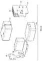
FIG. 2A shows a front left perspective view of a portion of the exemplary embodiment inFIG. 1 ; -
FIG. 2B shows another front left perspective view of another portion of the exemplary embodiment inFIG. 1 ; -
FIG. 2C shows a front left exploded view of the portion of the exemplary embodiment ofFIG. 1 shown inFIG. 2A ; -
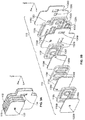
FIG. 3A shows a rear left view of an exemplary embodiment of another portion of the exemplary embodiment inFIG. 1 ; -
FIG. 3B shows a rear left exploded view ofFIG. 3A ; -
FIG. 4 depicts an exploded view of another exemplary embodiment; -
FIG. 5A depicts a right side view of another exemplary embodiment; -
FIG. 5B depicts a front right exploded view of the exemplary embodiment ofFIG. 5A ; -
FIG. 6 shows a graphical comparison of frequency responses of an exemplary labyrinth/manifold assembly, a 4 in. tube, and a 1 in. tube; and -
FIG. 7 shows a flow diagram for an exemplary embodiment. -
FIG. 1 depicts an exploded view of an earphone assembly. Theearphone 100 comprises acase 102a and acover 102b, which together form a housing or casing for the earphone. Acable 120 connects to the housing and provides an input signal to aconnector 109, typically in the form of an audio signal desired to be played by theearphone 100. Adriver assembly 108 can be placed within the housing on acarrier 106. Thecarrier 106 retains thedriver assembly 108. Theconnector 109 is held in place within the housing by thecase 102a and thecover 102b. Anozzle interface 110 is provided for acoustically connecting thedriver assembly 108 to anozzle 112, which can be configured to be replaceable by a user by way of a threadedcollar 114. Aguide pin 140 can be placed on one of thecase 102a or thecover 102b to provide for additional sealing of thecase 102a and thecover 102b and to aid in the manufacturing of theearphone 100. - As shown in
FIGS. 1 ,2A-2C , thedriver assembly 108 comprises a duallow frequency driver 122, amid-frequency driver 124, ahigh frequency driver 126, anacoustic seal 116, which can be formed of Poron®, a manifold 118, alabyrinth 119 and acrossover flex PCB 128. Thedrivers labyrinth 119 within the housing for theearphone 100. Thelabyrinth 119 and the manifold 118 can each be formed as box-like or as a prism. Thelabyrinth 119 and the manifold 118 together can form an integral structure for mounting thedrivers low frequency driver 122 is mounted on a face of thelabyrinth 119, and themid-frequency driver 124 and thehigh frequency driver 126 can be mounted on a common face of themanifold 118. In one exemplary embodiment, thedrivers - The
labyrinth 119 and the manifold 118 together form anelongated passageway 130 for receiving the acoustic output from the duallow frequency driver 122 and together and separately act as an acoustic filtering structure. The manifold 118 is also provided with amid-frequency port 132 for receiving the acoustic output from themid-frequency driver 124, and ahigh frequency port 134 for receiving the acoustic output from thehigh frequency driver 126. Each of theelongated passageway 130, themid-frequency port 132, and thehigh frequency port 134 can share the common integral structure formed by thelabyrinth 119 and themanifold 118. - The
acoustic seal 116 is provided with afirst port 136 configured to receive the outputs from the manifoldhigh frequency port 134 and themid-frequency port 132. Theacoustic seal 116 is also provided with asecond port 138 configured to receive the output from theelongated passageway 130. Thefirst port 136 of theacoustic seal 116 can act as a mixing area for thehigh frequency driver 126 and themid-frequency driver 124. However, it is contemplated that theacoustic seal 116 can be arranged in any number of different ways to mix the various outputs of thedrivers mid-frequency driver 124 sound output could be mixed with the sound output from the dual low-frequency driver 122 in theacoustic seal 116. This may depend on the particular design parameters for the earphone. It may be desirable to route the paths of the drivers to add acoustic resistance or dampers to specific pathways of the drivers. For example, high damping may be required on the low frequency driver path, and the mid-frequency driver and the low frequency driver can share similar damping. - An exemplary embodiment of the
labyrinth 119 and the manifold 118 is shown inFIGS. 3A and 3B . In this embodiment, as shown in an exploded view inFIG. 3B , thelabyrinth 119 can be formed as a series of stacked layers orplates 119a-119f. Likewise, the manifold 118 can be formed as a series of stacked layers orplates 118a-118c. The stacked layers may be made of metal or other appropriate material. - The
elongated passageway 130 forms thelabyrinth 119, and travels through themanifold 118. Theelongated passageway 130 is a long maze-like channel that has multiple turns winding and twisting through thelabyrinth 119 and the manifold 118 contained within thehousing elongated passageway 130 essentially acts as a long tube folded up into the constrained volume of theearphone 100. Theelongated passageway 130 or long path acts as an acoustic transmission line, and in simple terms acts as a low pass filter in the low frequency range. In other words, theelongated passage 130 in the manifold 118 attenuates high frequency energy output from the duallow frequency driver 122. - The
low frequency channel 130 is formed by providing alternatinglayers ports elongated passageways labyrinth 119 and in themanifold 118. Each of theports elongated passageways labyrinth 119 andmanifold 118. - The
elongated passageways layers layers elongated passageways layers ports FIG. 3B , the first subset and the second subset can be configured to alternate between each other. - The
elongated passageways layer 118b on the manifold 118 has a larger surface area than thelayers labyrinth 119 and, thus, can provide a longerelongated channel 130h. Theelongated passages low frequency driver 122 to travel. This network ofelongated passageways elongated passage 130 can be formed as an irregular tortuous path and in different shapes and arrangements as depicted inFIG. 3B , for example, spiral, wave, etc. Other shapes and configurations that achieve an elongated passageway are also contemplated. - Moreover, as shown in
FIG. 3B theelongated passageway 130 provides a pathway for sound in all three dimensions X, Y, and Z throughout thelabyrinth 119 and themanifold 118. Additionally, theelongated passageway 130 can be formed with a constant diameter or the same diameter throughout thelabyrinth 119 and the manifold 118 to provide the requisite amount of acoustic inertance in thepassageway 130. The sound will move within theelongated passageway 130 in each of the X, Y, and Z directions such that a substantial amount of the volume taken up by thelabyrinth 119 and the manifold 118 provides pathway for the sound to travel from the duallow frequency driver 122, thereby filtering the acoustical output from thelow frequency driver 122. - The
high frequency port 134 and themid-frequency port 132 can be formed using a similar method as thelow frequency channel 130. Themid-frequency port 132 can be formed in thesuccessive layers 118a-118c of the manifold 118 by forming individual slots oropenings layers 118a-118c. Likewise, thehigh frequency port 134 can be formed in thesuccessive layers 118a-118c of the manifold 118 by forming individual slots oropenings layers 118a-118c. - The
layers 119a-119f and 118a-118c can be formed by new laser cutting methods, which allow for the tight control and precision that is needed to form an accurate cross section in thelabyrinth 119 and themanifold 118. Thelayers 119a-119f and 118a-118c may be formed of metal, plastic, or any other appropriate materials formed into the geometric configurations described herein. Theindividual layers 119a-119f and 118a-118c of thelabyrinth 119 and the manifold 118 can be glued or welded together. In one exemplary embodiment, each layer of thelabyrinth 119 and the manifold 118 can be laser welded along its outside edge along the perimeter and then thelayers 119a-119f and 118a-118c of thelabyrinth 119 andmanifold 118 can be laser welded on the edge surfaces in a direction perpendicular to the largest surface areas of the layers. Other techniques known in the art are also contemplated for securing theindividual layers 119a-119f and 118a-118c of thelabyrinth 119 and themanifold 118. Thelayers 119a-119f of the labyrinth and thelayers 118a-118c of the manifold can be laser cut and laser welded or glued together. However, it is also contemplated that other methods of forming thelabyrinth 119 and the manifold 118 known in the art can be used, such as micro lithography, stereo lithography, or 3D printing. - As shown in
FIG. 3B theelongated passageway 130 as formed in thelayers 119a-119f and 118a-118c provides a much greater path length than the width or length of thelabyrinth 119 or the individual widths and lengths of theindividual layers 119a-119f and 118a-118c that form thelabyrinth 119 and themanifold 118. As a result, the elongated passageways orchannels elongated passageway 130 per unit volume of thelabyrinth 119. - The design of the manifold 118 takes up very little space (volumetrically) and uses only an acoustical technique to filter out higher frequency sounds. The
elongated passageway 130, which forms a maze-like passage in thelabyrinth 119 and the manifold 118, which again essentially acts as a long tube which can be folded up and fit in the space-constrained volume of an in-ear earphone. The volume of an earphone is space constrained. In particular, many components must fit within the earphone casing, as discussed above, for example, thedriver assembly 108, theacoustic seal 116, thenozzle interface 110, etc. all must be fit within the earphone casing. - In one exemplary embodiment, the ratio of length to volume of the
elongated passage 130 within the labyrinth is over 1.5 m-2. For silicone tubing typically used in the art, the length to volume ratio is approximately 0.27 m-2, which means that in one exemplary embodiment the labyrinth provides almost six times as much sound passage length per volume than a typical silicone tube. This advantageously provides the desired amount of filtering of high frequency sound within the earphone. - Another measure of the efficiency of the elongated passageway in the labyrinth as a low pass filter is the acoustic mass to volume ratio. Acoustic mass can also be referred to as the inertance, which for tubes can be calculated by the equation listed above. As discussed herein, it is difficult to provide the requisite amount of inertance within the small amount of space in an earphone. However, the labyrinth helps to overcome this difficultly in providing an acoustic mass to volume ratio of approximately 1.3 x 10¹³ kg/m7. A typical silicone tube provides an acoustic mass to volume ratio of a 4.2 x 10¹¹ kg/m7, meaning that the labyrinth design can provide approximately 31 times more acoustic mass in a given volume than can a typical silicone tube.
-
FIG. 6 shows a comparison between a 1 in. (25 mm) length tube, which has a volume of 93 mm3, a 4 in. (100 mm) tube having a volume of 372 mm3, and thelabyrinth 118/manifold 119 design described herein, which has a volume of 65 mm3 and an effective length of 4 in. The graph shows that thelabyrinth 118/manifold 119 design is able to provide a much improved cut-off frequency and low pass filter response, and more significantly, is capable of delivering this performance improvement while requiring far less volume than that required by a typical tube used in the art. Thelabyrinth 119 together with the manifold 118 provide over five times more acoustic mass at a sixth of the volume of an equivalent length tube typically used in the art. This results in cut-off frequency shifting downward from 330 Hz to 75 Hz, and a better performing low pass filter response. Additionally, thelabyrinth 119 andmanifold 118 design are also smaller volumetrically than a 1 in. (25 mm) tube that is typically used in the art and provides a better performing low pass filter response. - The viscous losses associated with the flow of acoustic volume velocity through the small cross-sectional area of the labyrinth effectively function to dampen the transmission-line half-wavelength resonance that would be present at roughly 1600 Hz. This resonance frequency coincides with an impedance minimum in the transmission line response function. In the absence of damping, this impedance null would permit the passage of undesirable high frequency sound waves. With the sufficient viscous damping provided by the small cross-section of the
labyrinth 119 and the manifold 118, however, these high frequency sound waves are prevented from being transmitted through thelabyrinth 119 and themanifold 118. - The
elongated passageway 130 allows the acoustic output signals of the duallow frequency driver 122, which is focused on reproducing only low frequencies (in a multi-driver earphone) to dedicate itself only to the low-frequency content in an audio signal. This provides a few advantages: (1) the output level of low frequency content can be adjusted independent of mid and low frequency octave bands, which is often difficult to narrowly adjust in one or two driver systems (2) the cutoff frequency (knee) of the low pass filter can be set and controlled by the geometry (cross-sectional area and length) of the internal acoustic path of theelongated passageway 130 and (3) the driver(s) producing mid to high frequency energy no longer have to reproduce low frequency components of the source material, which reduces the potential for inter-modulation type distortions where the higher frequency component is modulating on top of the larger low frequency excursions and not faithfully reproducing the original source material as intended. - In one exemplary embodiment, the cross sectional area of the
labyrinth 119 can be square like at 0.0155" x 0.0160" (0.0002325 in2) (0.394 mm x 0.406 mm (0.1500 mm2)). In one embodiment, the path length of theelongated passageway 130 of the device built can be 4.23" (107 mm) long and the path width or diameter can be 0.015 in. (0.38 mm), which results in a desirable cut-off frequency (-3dB location re 20 Hz) of 63 Hz for the first-order filter (-6dB per octave slope), in the frequency range up to 800 Hz in which the labyrinth functions as a lumped acoustic mass element. - In alternative embodiments, multiple elongated passageways can be created in the
labyrinth 119 and the manifold 118 so that sound from the various drivers can be filtered. In one example, both the duallow frequency driver 122 and themid-frequency driver 124 can be provided with an extended length passage in either thelabyrinth 119 or the manifold 118 such that higher frequency sound can be filtered from each of the drivers to provide the desired sound output characteristics from the earphone. Similar to thelow frequency driver 122, it may be beneficial to roll off higher frequencies from the mid frequency driver. To accomplish this, the passageways in thelabyrinth 119 and the manifold 118 can be configured to provide a low pass filter at a higher knee or focused on rolling off higher frequencies output from themid-frequency driver 124. Providing an acoustic filter for the mid-frequency driver (1) may reduce the frequency overlap with the high-frequency driver 126 to provide an improved frequency response, (2) may eliminate the need to use electrical filtering on the high-frequency driver 126, and (3) may introduce additional inertance in the signal path of themid-frequency driver 124 to shift peak frequencies lower for a desired frequency response shape. - In another alternative embodiment, the
labyrinth 119 and the manifold 118 together can act as a mounting location for attaching a shock absorbing mount or to assist with holding the case parts or housing parts together. For example, integrating extending features in thelayers 119a-f of thelabyrinth 119 and thelayers 118a-c of the manifold 118 for mechanical purposes could reduce part complexity and costs. Any or all of thelayers 119a-f, 118a-c of thelabyrinth 119 or the manifold 118 could be utilized for this purpose to build up extending legs or connecting points for purposes such as but not limited to: a) creating indexing or keying features to assist with the assembly of the part(s), b) features to integrate with shock mounting materials, c) geometric (3D) features that assist with locating the driver sub-assembly within the housing, or d) cosmetic or industrial design elements for ornamental purposes. - In another alternative embodiment, resistance damping can be added into the
elongated passage 130, themid-frequency port 132, thehigh frequency port 134, and/or thelayers 119a-119f of thelabyrinth 119 or thelayers 118a-118c of the manifold 118 to increase resistance and customize individual driver responses depending on the desired sound output for the earphone. - An example of resistance damping integrated into structure of the manifold is shown in
FIG. 4 , where like reference numerals represent like components as the embodiment depicted inFIGS. 3A and 3B . The exemplary embodiment shown inFIG. 4 is similar to the embodiment shown inFIGS. 3A and 3B , except that the manifold 418 is formed with anadditional layer 418c having a built-in matrix 432c that acts as a damping mechanism. As shown inFIG. 4 , an [n x m] matrix 432c of tiny holes (40 to 80 micron diameter) are formed into thelayer 418c of themanifold 418. The matrix 432c of tiny holes is designed to meet a target acoustical resistance value for viscous damping purposes, which is a different mechanism than the inertance method used in thelabyrinth 419 discussed herein. In this particular embodiment, 9 columns x 6 rows (54 holes) of 80 micron diameter holes evenly distributed over the mid-frequency path are used to form the matrix 432c. This provides a flexible method to damp the mid-frequency port orpath 432a-432d with different resistance values. Additionally, any of the paths 430, 432, or 434 formed in thelabyrinth 419 and the manifold 418 could be independently damped using this method. - In one exemplary embodiment, the
layer 418c can be an electroformed layer of Nickel and can be formed very thin (roughly 0.001" (0.025 mm) thick). Additionally, thelayers layer 418c. This locks thedissimilar metal layer 418c into the assembly and provides a robust integral structure for forming themanifold 418. -
FIGS. 5A and 5B depict another exemplary embodiment of thelabyrinth 319 and themanifold 318. This design is similar to the design shown and described above inFIGS. 3A and 3B , and similarly numbered components represent like components in the previous embodiment. However, thefinal pathway 330h in the front of the manifold 119 has a different shape and configuration. Additionally, thelow frequency output 330,mid-frequency output 332, and thehigh frequency output 334 can be arranged in different locations based on the design of the earphone. - The operation of the exemplary embodiments disclosed herein will now be described with respect to
FIGS. 1-3B and the flow diagram shown inFIG. 7 . To reproduce a sound signal in the earphone, thecable 120 outputs a signal from aninput 142 or sound source such as a mobile device, mp3 player, bodypack transmitter, etc. The signal is then transferred through theconnector 109 and to thecrossover flex PCB 128. Thecrossover flex PCB 128 divides the signal into low, mid, and high frequency portions of the signal and routes the low, mid, and high frequency portions of the signal to the corresponding duallow frequency driver 122,mid-frequency driver 124, orhigh frequency driver 126. The respective signals cause the drivers to output sound through thelabyrinth 119 and themanifold 118. The sound output from the mid andhigh frequency drivers mid-frequency port 132 andhigh frequency port 134 respectively. However, the sound output by the duallow frequency driver 122 is output through theelongated passageway 130 formed in thelabyrinth 119 and themanifold 118. The acoustic inertance of theelongated passageway 130 then provides a first-order low-pass filter for the sound output from thelow frequency driver 122 to attenuate undesirable high frequencies above the filter's corner frequency. - The sound from the
high frequency port 134 and the sound from themid-frequency port 132 are then output into theacoustic seal 116first port 136. Thefirst port 136 of theacoustic seal 116 mixes the outputs from thehigh frequency driver 126 and themid-frequency driver 124. Theacoustic seal 116second port 138 receives the output from the duallow frequency driver 122 through theelongated passage 130. The separate outputs from thefirst port 136 and thesecond port 138 of theacoustic seal 116 are then transferred into thenozzle interface 110. Each separate output is provided to thenozzle 112 from thenozzle interface 110. Thenozzle 112 can also be configured to maintain the outputs acoustically separate until the sound reaches the end of thenozzle 112. Thenozzle 112 mates with a sleeve (not shown), which is inserted into a user's ear and couples theearphone 100 to a user's ear. Thenozzle 112 is configured to project the sound directly into a user's ear canal. The flow diagram inFIG. 7 generally diagrams how the sound will travel through an earphone disclosed in the embodiments inFIGS. 1-5B . - Aspects of the invention have been described in terms of illustrative embodiments thereof. Numerous other embodiments, modifications and variations within the scope of the disclosed invention as defined by the claims will occur to persons of ordinary skill in the art from a review of this entire disclosure. For example, one of ordinary skill in the art will appreciate that the steps illustrated in the illustrative figures may be performed in other than the recited order, and that one or more steps illustrated may be optional in accordance with aspects of the disclosure as defined by the claims.
Claims (13)
- An earphone assembly (100) comprising:a housing (102a, 102b; 202a, 202b);a first driver (122) configured to produce a first audio output;a second driver (124; 126) configured to produce a second audio output;a nozzle (112) coupled (110) to the housing; andan elongated passageway (130; 202a, 202b; 430) connected to the first driver and contained within the housing, the elongated passageway having a length and cross sectional area and comprising a tortuous path having multiple turns winding internally within the housing, wherein the length and cross-sectional area of the elongated passageway are configured as an acoustic filter for filtering at least an audible portion of the sound from the audio output of the first driver;wherein at least a portion of the elongated passageway forms a labyrinth (119; 419);characterised in that the labyrinth comprises a plurality of integral layers (119a-f; 419a-f).
- The earphone assembly of claim 1 wherein one or more of the layers (119b; 119d; 119f; 419b; 419d; 419f) of the labyrinth form an elongated channel (130b; 130d; 130f; 330b; 330d; 330f; 430b; 430d; 430f) extending lengthwise, widthwise, or combinations thereof on the largest surface area of the layer.
- The earphone assembly of claim 2 wherein the elongated channel of the one or more layers is formed as a wave (130d; 330d; 430d) or spiral (130b; 130f; 330b; 330f; 430b; 430f) shape.
- The earphone assembly of claim 2 further comprising a manifold (118; 418) wherein the manifold comprises a passageway (130h; 430h) which forms part of the elongated passageway (130).
- The earphone assembly of claim 4 wherein the manifold comprises a plurality of integral layers (118a-c; 418a-d) wherein one or more of the layers (118b; 418b) of the manifold form an elongated channel and wherein an elongated channel (130h; 430h) formed in one or more of the layers of the manifold is a greater length than the length of an elongated channel (130b; 130d; 130f; 330b; 330d; 330f; 430b; 430d; 430f) formed in one or more of the layers of the labyrinth; and/or
wherein the manifold further comprises an additional passageway (132; 134; 432; 434) for receiving sound directly from the second driver, the second driver configured to output a higher frequency sound than the first driver; and/or
wherein a damping mechanism is provided in the manifold and wherein the damping mechanism comprises a plurality of holes (432c) formed into a layer (418c) forming the manifold. - The earphone assembly of claim 1 wherein at least a portion of the shape of the elongated passageway is spiral or wave.
- The earphone assembly of claim 1 wherein the elongated passageway (202a, 202b) is integrally formed within a portion (200) of the housing.
- A method of filtering an acoustic output in an earphone (100) comprising:forming an elongated passageway (130; 202a; 202b) from a plurality of stacked layers (119a-f; 419a-f; 118a-c; 418a-d);housing the elongated passageway and at least one low frequency driver (122) configured to provide an acoustic output within an earphone casing (102a, 102b; 202a, 202b);connecting the output of the at least one driver to the elongated passageway and configuring the acoustic output to be received within the elongated passageway to acoustically filter and roll off at least a portion of the acoustic output from the at least one driver to filter high frequency sound from the low frequency driver;wherein at least a portion of the elongated passageway forms a labyrinth (119; 419);characterised in that the labyrinth comprises a plurality of integral layers (119a-f; 419a-f).
- The method of claim 8 wherein a first subset (119b; 119d; 119f; 118b; 419b; 419d; 419f; 418b) of the stacked layers have passages (130b; 130d; 130f; 130h; 430b; 430d; 430f; 430h; 330b; 330d; 330f; 330h) formed of different shapes.
- The method of claim 9 wherein a second subset (119a; 119c; 119e; 118a; 118c; 419a; 419c; 419e; 418a; 418c; 418d) of the stacked layers have holes (130a; 130c; 130e; 130g; 132a; 134a; 130i; 132c; 134c; 430a; 430c; 430e; 430g; 432a; 434a; 430i; 434c; 430j; 432d; 434d; 330a; 330c; 330e) permitting sound to pass through each of the second subset of stacked layers into an adjoining one of the first subset of the stacked layers; preferably
wherein the plurality of stacked layers comprises alternating layers of the first and second subsets. - The method of claim 9 further comprising laser welding the stacked layers together.
- The method of claim 8 further comprising providing a manifold (118; 418) wherein the elongated passageway is partially formed (130h; 430h) within the manifold (118b; 418b); preferably
wherein the method further comprises forming the manifold from a series of stacked layers (118a-c; 418a-d). - The method of claim 8 further comprising forming at least a portion of the path of the elongated passageway as a wave or a spiral shape.
Applications Claiming Priority (2)
| Application Number | Priority Date | Filing Date | Title |
|---|---|---|---|
| US13/477,874 US8983101B2 (en) | 2012-05-22 | 2012-05-22 | Earphone assembly |
| PCT/US2013/038603 WO2013176840A1 (en) | 2012-05-22 | 2013-04-29 | Earphone assembly |
Publications (2)
| Publication Number | Publication Date |
|---|---|
| EP2853099A1 EP2853099A1 (en) | 2015-04-01 |
| EP2853099B1 true EP2853099B1 (en) | 2017-11-08 |
Family
ID=48428659
Family Applications (1)
| Application Number | Title | Priority Date | Filing Date |
|---|---|---|---|
| EP13722206.3A Active EP2853099B1 (en) | 2012-05-22 | 2013-04-29 | Earphone assembly |
Country Status (8)
| Country | Link |
|---|---|
| US (2) | US8983101B2 (en) |
| EP (1) | EP2853099B1 (en) |
| JP (1) | JP6275125B2 (en) |
| KR (1) | KR101968569B1 (en) |
| CN (1) | CN104412615B (en) |
| ES (1) | ES2647824T3 (en) |
| TW (1) | TWI599233B (en) |
| WO (1) | WO2013176840A1 (en) |
Families Citing this family (38)
| Publication number | Priority date | Publication date | Assignee | Title |
|---|---|---|---|---|
| US9210497B2 (en) * | 2012-09-06 | 2015-12-08 | Shure Acquisition Holdings, Inc. | Electrostatic earphone |
| US9241209B2 (en) * | 2013-06-25 | 2016-01-19 | Google Inc. | Headphones with adaptable fit |
| EP2908551A1 (en) | 2014-02-14 | 2015-08-19 | Sonion Nederland B.V. | A joiner for a receiver assembly |
| TWM482225U (en) * | 2014-03-28 | 2014-07-11 | Verisonix Corp | Improved integrated electrostatic earphone monomer module structure |
| TWI572215B (en) * | 2015-01-05 | 2017-02-21 | 致伸科技股份有限公司 | Earphone structure |
| TWM500412U (en) * | 2015-01-14 | 2015-05-01 | Jetvox Acoustic Corp | Earphone structure having port tube |
| US9412356B1 (en) * | 2015-02-09 | 2016-08-09 | Doppler Labs, Inc. | Apparatus and method for non-occluded active noise shaping |
| TWM508868U (en) * | 2015-04-24 | 2015-09-11 | Jetvox Acoustic Corp | Reverse acoustic earphone |
| US10097913B2 (en) | 2015-09-30 | 2018-10-09 | Apple Inc. | Earbud case with charging system |
| CN105323700A (en) * | 2015-12-02 | 2016-02-10 | 逢甲大学 | Manufacturing Method of Customized In-Ear Headphones |
| KR101756653B1 (en) * | 2015-12-30 | 2017-07-17 | 주식회사 오르페오사운드웍스 | Noise shielding earset with acoustic filter |
| US10091576B2 (en) * | 2016-02-16 | 2018-10-02 | Campfire Audio Llc | In-ear monitor |
| US10536769B2 (en) | 2016-05-02 | 2020-01-14 | Dolby International Ab | Sealed pipe-loaded loudspeaker for improving low frequency response in portable devices |
| JP6737098B2 (en) * | 2016-09-15 | 2020-08-05 | 株式会社Jvcケンウッド | earphone |
| CN110149566B (en) * | 2016-07-11 | 2021-07-06 | Jvc 建伍株式会社 | Earphone set |
| CN106210583A (en) * | 2016-08-01 | 2016-12-07 | 苏州倍声声学技术有限公司 | A kind of unmanned plane recording system |
| US9860645B1 (en) | 2017-01-05 | 2018-01-02 | Ryan C. Tsui | Multi-driver air-tube earphone |
| US10171902B2 (en) * | 2017-03-29 | 2019-01-01 | Campfire Audio Llc | In-ear monitor |
| EP3530003A4 (en) * | 2017-06-29 | 2020-02-26 | Shenzhen Goodix Technology Co., Ltd. | USER CUSTOMIZABLE HEADPHONE SYSTEM |
| US10986432B2 (en) * | 2017-06-30 | 2021-04-20 | Bose Corporation | Customized ear tips |
| USD890696S1 (en) | 2017-07-21 | 2020-07-21 | Google Llc | Earbud charging case |
| USD867326S1 (en) | 2017-07-21 | 2019-11-19 | Google Llc | Wireless earbuds |
| USD896781S1 (en) | 2017-08-04 | 2020-09-22 | Google Llc | Audio assembly |
| USD844586S1 (en) | 2017-08-04 | 2019-04-02 | Google Llc | Audio assembly |
| US10645478B2 (en) | 2017-12-08 | 2020-05-05 | Skullcandy, Inc. | In-ear headphone for improved fit and function, and related methods |
| USD879075S1 (en) | 2018-07-11 | 2020-03-24 | Google Llc | Earbud stand assembly |
| JP2018160944A (en) * | 2018-07-20 | 2018-10-11 | Ttr株式会社 | Canal type earphone |
| US11172101B1 (en) | 2018-09-20 | 2021-11-09 | Apple Inc. | Multifunction accessory case |
| CN109246524A (en) * | 2018-11-05 | 2019-01-18 | 苏州全频智能科技有限公司 | A kind of In-Ear Headphones |
| JP7247549B2 (en) | 2018-11-29 | 2023-03-29 | ヤマハ株式会社 | Electroacoustic transducer |
| TWI687105B (en) * | 2018-12-20 | 2020-03-01 | 英屬開曼群島商康而富控股股份有限公司 | Inner mold assembly formed by using metal strip |
| KR102203295B1 (en) * | 2019-12-11 | 2021-01-14 | 부전전자 주식회사 | Grill Integral type Low Pass Filter and Speaker Having The Same |
| US11818536B2 (en) | 2020-11-18 | 2023-11-14 | Shure Acquisition Holdings, Inc. | Audio devices having low-frequency extension filter |
| DK181069B1 (en) | 2020-12-23 | 2022-11-08 | Gn Hearing 2 As | Magnet shielding by using a magnetisable plate |
| DK202070871A1 (en) | 2020-12-23 | 2022-06-24 | Gn Hearing 2 As | Magnet shielding by using a non-magnetic element |
| CN113055777A (en) * | 2021-03-12 | 2021-06-29 | 深圳快听科技有限公司 | Noise reduction device and noise reduction earphone |
| GB2629281A (en) * | 2022-01-31 | 2024-10-23 | Apple Inc | Two-part speaker system |
| WO2024017783A1 (en) * | 2022-07-21 | 2024-01-25 | Sonion Nederland B.V. | Audio assembly with acoustical mass for hearing devices |
Citations (1)
| Publication number | Priority date | Publication date | Assignee | Title |
|---|---|---|---|---|
| US20110255723A1 (en) * | 2010-04-14 | 2011-10-20 | Obradovic Gojko | Hearing aid |
Family Cites Families (82)
| Publication number | Priority date | Publication date | Assignee | Title |
|---|---|---|---|---|
| BE797139A (en) | 1973-03-21 | 1973-07-16 | Doms Jan B | IMPROVEMENTS TO SOUND FURNITURE, FOR MICROPHONE AND / OR LOUDSPEAKER |
| JPS5843700A (en) * | 1981-09-09 | 1983-03-14 | Rion Co Ltd | Ear-insertion type hearing aid |
| US4628528A (en) * | 1982-09-29 | 1986-12-09 | Bose Corporation | Pressure wave transducing |
| JPH0633749Y2 (en) * | 1989-04-12 | 1994-08-31 | 株式会社ケンウッド | Speaker system for bass reproduction |
| JPH03162099A (en) * | 1989-11-20 | 1991-07-12 | Sony Corp | Headphone device |
| US5887070A (en) | 1992-05-08 | 1999-03-23 | Etymotic Research, Inc. | High fidelity insert earphones and methods of making same |
| JP3479993B2 (en) * | 1993-03-31 | 2003-12-15 | 松下電器産業株式会社 | Speaker device |
| US5452268A (en) * | 1994-08-12 | 1995-09-19 | The Charles Stark Draper Laboratory, Inc. | Acoustic transducer with improved low frequency response |
| US5549658A (en) | 1994-10-24 | 1996-08-27 | Advanced Bionics Corporation | Four-Channel cochlear system with a passive, non-hermetically sealed implant |
| US5692059A (en) | 1995-02-24 | 1997-11-25 | Kruger; Frederick M. | Two active element in-the-ear microphone system |
| US5694475A (en) | 1995-09-19 | 1997-12-02 | Interval Research Corporation | Acoustically transparent earphones |
| US5878147A (en) | 1996-12-31 | 1999-03-02 | Etymotic Research, Inc. | Directional microphone assembly |
| US6205227B1 (en) | 1998-01-31 | 2001-03-20 | Sarnoff Corporation | Peritympanic hearing instrument |
| US6129174A (en) | 1998-12-30 | 2000-10-10 | Decibel Instruments, Inc. | Minimal contact replaceable acoustic coupler |
| US6724902B1 (en) | 1999-04-29 | 2004-04-20 | Insound Medical, Inc. | Canal hearing device with tubular insert |
| US7394909B1 (en) | 2000-09-25 | 2008-07-01 | Phonak Ag | Hearing device with embedded channnel |
| US7181035B2 (en) | 2000-11-22 | 2007-02-20 | Sonion Nederland B.V. | Acoustical receiver housing for hearing aids |
| DE60122935T8 (en) | 2000-12-22 | 2008-02-14 | Nextlink Ipr Ab | ACOUSTIC EQUIPMENT WITH MEANS IN A HUMAN EAR ATTACHED MEDIUM |
| US7103196B2 (en) | 2001-03-12 | 2006-09-05 | Knowles Electronics, Llc. | Method for reducing distortion in a receiver |
| EP1481570B1 (en) | 2002-03-05 | 2010-07-28 | Audio Products International Corp. | Loudspeaker with shaped sound field |
| EP1483936B1 (en) | 2002-03-06 | 2009-03-18 | Koninklijke Philips Electronics N.V. | Headphone |
| JP3914449B2 (en) * | 2002-03-28 | 2007-05-16 | パイオニア株式会社 | Speaker device |
| USD488460S1 (en) | 2002-12-09 | 2004-04-13 | Shure Incorporated | Earphone |
| US20050018838A1 (en) | 2003-03-03 | 2005-01-27 | Shure Incorporated | Communications headset with isolating in-ear driver |
| CA2526269A1 (en) * | 2003-05-19 | 2004-11-25 | Widex A/S | A hearing aid |
| USD494956S1 (en) | 2003-11-26 | 2004-08-24 | Shure Incorporated | Earphone |
| US7508953B2 (en) | 2003-12-30 | 2009-03-24 | Audio Products International Corp. | Loudspeaker and components for use in construction thereof |
| CA2552802A1 (en) | 2004-01-07 | 2005-07-28 | Etymotic Research, Inc. | One-size-fits-most hearing aid |
| US7570777B1 (en) | 2004-01-13 | 2009-08-04 | Step Labs, Inc. | Earset assembly |
| EP1594340B1 (en) | 2004-05-03 | 2012-05-30 | GN ReSound A/S | Flexible ear piece for a hearing aid |
| US20050249369A1 (en) | 2004-05-05 | 2005-11-10 | Phonak Ag | Flexible frequency response shaping |
| WO2005112602A2 (en) | 2004-05-21 | 2005-12-01 | Logitech Europe S.A. | Speaker with frequency directed dual drivers |
| US7369670B2 (en) | 2004-08-25 | 2008-05-06 | Phonak Ag | Earplug and method for manufacturing the same |
| US20060042867A1 (en) | 2004-08-25 | 2006-03-02 | Phonak Ag | Hearing protection earplug and method for manufacturing such an earplug |
| US7512243B2 (en) | 2004-08-25 | 2009-03-31 | Phonak Ag | Hearing protection earplug with a movable attenuation button, method for manufacturing the same and use of the same |
| US7240765B2 (en) | 2004-08-25 | 2007-07-10 | Phonak Ag | Customized hearing protection earplug with an acoustic filter and method for manufacturing the same |
| DK2416589T3 (en) | 2004-11-01 | 2018-03-12 | Sonion Nederland Bv | Electroacoustic transducer and transducer device |
| US7616772B2 (en) | 2004-11-09 | 2009-11-10 | Shure Acquisition Holdings, Inc. | Earphone for sound reproduction |
| USD519103S1 (en) | 2004-11-09 | 2006-04-18 | Shure Incorporated | Earphone |
| US7317806B2 (en) * | 2004-12-22 | 2008-01-08 | Ultimate Ears, Llc | Sound tube tuned multi-driver earpiece |
| US7263195B2 (en) | 2004-12-22 | 2007-08-28 | Ultimate Ears, Llc | In-ear monitor with shaped dual bore |
| USD542773S1 (en) | 2005-06-20 | 2007-05-15 | Etymotic Research, Inc. | High fidelity noise excluding earphones with ergonomically designed construction |
| US7991179B2 (en) | 2005-06-20 | 2011-08-02 | Etymotic Research, Inc. | High fidelity noise-excluding earphones with ergonomically designed construction |
| US7634099B2 (en) | 2005-07-22 | 2009-12-15 | Logitech International, S.A. | High-fidelity earpiece with adjustable frequency response |
| US7489794B2 (en) | 2005-09-07 | 2009-02-10 | Ultimate Ears, Llc | Earpiece with acoustic vent for driver response optimization |
| US7983433B2 (en) | 2005-11-08 | 2011-07-19 | Think-A-Move, Ltd. | Earset assembly |
| KR100694160B1 (en) | 2005-12-29 | 2007-03-12 | 삼성전자주식회사 | Earphone having variable duct part |
| US8107665B2 (en) | 2006-01-30 | 2012-01-31 | Etymotic Research, Inc. | Insert earphone using a moving coil driver |
| US8031900B2 (en) | 2006-02-27 | 2011-10-04 | Logitech International, S.A. | Earphone ambient eartip |
| WO2007140403A2 (en) | 2006-05-30 | 2007-12-06 | Knowles Electronics, Llc. | Personal listening device |
| JP5396271B2 (en) | 2006-06-23 | 2014-01-22 | ジーエヌ リザウンド エー/エス | Hearing aid having an elongated member removably connected |
| US7590258B2 (en) | 2006-07-05 | 2009-09-15 | Mark Andrew Krywko | In-ear earphone |
| USD550201S1 (en) | 2006-07-24 | 2007-09-04 | Etymotic Research, Inc. | Earphone |
| USD550200S1 (en) | 2006-07-24 | 2007-09-04 | Etymotic Research, Inc. | Earphone |
| EP1895811B1 (en) | 2006-08-28 | 2016-06-08 | Sonion Nederland B.V. | Multiple receivers with a common acoustic spout |
| CN101507292A (en) | 2006-08-31 | 2009-08-12 | 唯听助听器公司 | Filter for a hearing aid and hearing aid |
| CH699444B1 (en) | 2006-10-11 | 2010-03-15 | Phonak Ag | Hearing aid. |
| DK1926344T3 (en) | 2006-11-21 | 2012-01-02 | Sonion As | Connector assembly comprising a first portion and a second portion |
| US7831057B2 (en) | 2007-01-05 | 2010-11-09 | Audiovox Corporation | High output loudspeaker |
| JP4921197B2 (en) | 2007-02-06 | 2012-04-25 | スター精密株式会社 | Insertion type earphone |
| US8194911B2 (en) | 2007-03-27 | 2012-06-05 | Logitech International, S.A. | Earphone integrated eartip |
| US8391534B2 (en) | 2008-07-23 | 2013-03-05 | Asius Technologies, Llc | Inflatable ear device |
| US8135163B2 (en) | 2007-08-30 | 2012-03-13 | Klipsch Group, Inc. | Balanced armature with acoustic low pass filter |
| WO2009075834A1 (en) | 2007-12-10 | 2009-06-18 | Klipsch, Llc | In-ear headphones |
| FR2925291A1 (en) | 2007-12-21 | 2009-06-26 | Eatsonics Soc Par Actions Simp | ACOUSTICAL LINEAR ATTENUATION DEVICE FOR SOUND |
| USD618669S1 (en) | 2009-04-06 | 2010-06-29 | Koss Corporation | Earphone |
| US8792669B2 (en) | 2008-05-21 | 2014-07-29 | Phonak Ag | Earphone system and use of an earphone system |
| USD603844S1 (en) | 2008-05-29 | 2009-11-10 | Klipsch, Llc | Headphone |
| US8625831B2 (en) * | 2008-12-11 | 2014-01-07 | Widex A/S | Hearing aid earpiece and a method of manufacturing a hearing aid earpiece |
| EP2415278A4 (en) | 2009-04-01 | 2013-05-15 | Knowles Electronics Llc | Receiver assemblies |
| USD636492S1 (en) | 2009-04-30 | 2011-04-19 | Phonak Ag | Hearing aid |
| USD613726S1 (en) | 2009-06-23 | 2010-04-13 | Klipsch, Llc | Headphone |
| EP2285135A1 (en) | 2009-07-07 | 2011-02-16 | Nxp B.V. | Microphone-speaker device comprising a low pass filter |
| DE102009040050B4 (en) | 2009-09-03 | 2019-12-05 | Sennheiser Electronic Gmbh & Co. Kg | Ohrkanalhörer |
| EP2306755B1 (en) | 2009-09-03 | 2015-06-03 | AKG Acoustics GmbH | In-ear earphone |
| US8116502B2 (en) | 2009-09-08 | 2012-02-14 | Logitech International, S.A. | In-ear monitor with concentric sound bore configuration |
| US8649540B2 (en) | 2009-10-30 | 2014-02-11 | Etymotic Research, Inc. | Electronic earplug |
| WO2011050862A1 (en) | 2009-11-02 | 2011-05-05 | Phonak Ag | Hearing system comprising an earpiece |
| US8515103B2 (en) | 2009-12-29 | 2013-08-20 | Cyber Group USA Inc. | 3D stereo earphone with multiple speakers |
| DE102010015771B4 (en) | 2010-04-21 | 2013-08-08 | Siemens Medical Instruments Pte. Ltd. | Ear protection with adjustable damping |
| JP4681698B1 (en) * | 2010-10-05 | 2011-05-11 | 亮 山岸 | earphone |
| WO2011033136A2 (en) | 2011-01-07 | 2011-03-24 | Phonak Ag | Dynamic hearing protection device and method |
-
2012
- 2012-05-22 US US13/477,874 patent/US8983101B2/en active Active
-
2013
- 2013-04-29 CN CN201380035855.1A patent/CN104412615B/en active Active
- 2013-04-29 ES ES13722206.3T patent/ES2647824T3/en active Active
- 2013-04-29 WO PCT/US2013/038603 patent/WO2013176840A1/en not_active Ceased
- 2013-04-29 EP EP13722206.3A patent/EP2853099B1/en active Active
- 2013-04-29 JP JP2015514029A patent/JP6275125B2/en not_active Expired - Fee Related
- 2013-04-29 KR KR1020147036007A patent/KR101968569B1/en not_active Expired - Fee Related
- 2013-05-20 TW TW102117794A patent/TWI599233B/en not_active IP Right Cessation
-
2014
- 2014-12-09 US US14/564,940 patent/US9100761B2/en active Active
Patent Citations (1)
| Publication number | Priority date | Publication date | Assignee | Title |
|---|---|---|---|---|
| US20110255723A1 (en) * | 2010-04-14 | 2011-10-20 | Obradovic Gojko | Hearing aid |
Also Published As
| Publication number | Publication date |
|---|---|
| US20150092968A1 (en) | 2015-04-02 |
| KR20150021950A (en) | 2015-03-03 |
| JP6275125B2 (en) | 2018-02-07 |
| ES2647824T3 (en) | 2017-12-26 |
| EP2853099A1 (en) | 2015-04-01 |
| US9100761B2 (en) | 2015-08-04 |
| TW201412138A (en) | 2014-03-16 |
| US20130315431A1 (en) | 2013-11-28 |
| CN104412615A (en) | 2015-03-11 |
| US8983101B2 (en) | 2015-03-17 |
| JP2015521007A (en) | 2015-07-23 |
| CN104412615B (en) | 2017-12-12 |
| WO2013176840A1 (en) | 2013-11-28 |
| TWI599233B (en) | 2017-09-11 |
| KR101968569B1 (en) | 2019-08-13 |
Similar Documents
| Publication | Publication Date | Title |
|---|---|---|
| US9100761B2 (en) | Earphone assembly | |
| JP5405598B2 (en) | Speaker | |
| US8116502B2 (en) | In-ear monitor with concentric sound bore configuration | |
| US8098854B2 (en) | Multiple receivers with a common spout | |
| EP1685741B1 (en) | Sonic emitter arrangements | |
| US9042589B2 (en) | Custom fit in-ear monitors utilizing a single piece driver module | |
| EP2368372B1 (en) | Apparatus for reproduction of sound | |
| US10475435B1 (en) | Earphone having acoustic impedance branch for damped ear canal resonance and acoustic signal coupling | |
| JPH08172691A (en) | Inner ear headphones | |
| CN105556986A (en) | Coaxial effect two-way speaker | |
| JP3063639B2 (en) | Speaker device | |
| EP2647219B1 (en) | A method for optimizing performance of a multi-transducer earpiece and a multi-transducer earpiece | |
| JP6312785B2 (en) | Headphone | |
| US12212921B2 (en) | Apparatus for sound conversion with an acoustic filter | |
| KR101634236B1 (en) | Acoustic Hybrid Earphone With Acoustic Filter | |
| KR100577482B1 (en) | Bass speaker system | |
| JP2022073436A (en) | earphone | |
| KR20210051088A (en) | Earphone with a sound guiding tube |
Legal Events
| Date | Code | Title | Description |
|---|---|---|---|
| PUAI | Public reference made under article 153(3) epc to a published international application that has entered the european phase |
Free format text: ORIGINAL CODE: 0009012 |
|
| 17P | Request for examination filed |
Effective date: 20141219 |
|
| AK | Designated contracting states |
Kind code of ref document: A1 Designated state(s): AL AT BE BG CH CY CZ DE DK EE ES FI FR GB GR HR HU IE IS IT LI LT LU LV MC MK MT NL NO PL PT RO RS SE SI SK SM TR |
|
| AX | Request for extension of the european patent |
Extension state: BA ME |
|
| RIN1 | Information on inventor provided before grant (corrected) |
Inventor name: ZANONI, GABOR Inventor name: FROHLICH, LAJOS Inventor name: GLAVAN, KYLE PATRICK Inventor name: BRENEMAN, MARK BUI Inventor name: TSANGARIS, PARIS NICHOLAS Inventor name: GRINKER, SCOTT CHARLES Inventor name: GROSZ, STEVEN R. |
|
| DAX | Request for extension of the european patent (deleted) | ||
| 17Q | First examination report despatched |
Effective date: 20151207 |
|
| STAA | Information on the status of an ep patent application or granted ep patent |
Free format text: STATUS: EXAMINATION IS IN PROGRESS |
|
| GRAP | Despatch of communication of intention to grant a patent |
Free format text: ORIGINAL CODE: EPIDOSNIGR1 |
|
| STAA | Information on the status of an ep patent application or granted ep patent |
Free format text: STATUS: GRANT OF PATENT IS INTENDED |
|
| INTG | Intention to grant announced |
Effective date: 20170413 |
|
| GRAJ | Information related to disapproval of communication of intention to grant by the applicant or resumption of examination proceedings by the epo deleted |
Free format text: ORIGINAL CODE: EPIDOSDIGR1 |
|
| STAA | Information on the status of an ep patent application or granted ep patent |
Free format text: STATUS: EXAMINATION IS IN PROGRESS |
|
| INTC | Intention to grant announced (deleted) | ||
| RIN1 | Information on inventor provided before grant (corrected) |
Inventor name: GLAVAN, KYLE PATRICK Inventor name: TSANGARIS, PARIS NICHOLAS Inventor name: BRENEMAN, MARK BUI Inventor name: FROHLICH, LAJOS Inventor name: ZANONI, GABOR Inventor name: GROSZ, STEVEN R. Inventor name: GRINKER, SCOTT CHARLES |
|
| GRAR | Information related to intention to grant a patent recorded |
Free format text: ORIGINAL CODE: EPIDOSNIGR71 |
|
| GRAS | Grant fee paid |
Free format text: ORIGINAL CODE: EPIDOSNIGR3 |
|
| STAA | Information on the status of an ep patent application or granted ep patent |
Free format text: STATUS: GRANT OF PATENT IS INTENDED |
|
| GRAA | (expected) grant |
Free format text: ORIGINAL CODE: 0009210 |
|
| STAA | Information on the status of an ep patent application or granted ep patent |
Free format text: STATUS: THE PATENT HAS BEEN GRANTED |
|
| INTG | Intention to grant announced |
Effective date: 20170928 |
|
| AK | Designated contracting states |
Kind code of ref document: B1 Designated state(s): AL AT BE BG CH CY CZ DE DK EE ES FI FR GB GR HR HU IE IS IT LI LT LU LV MC MK MT NL NO PL PT RO RS SE SI SK SM TR |
|
| REG | Reference to a national code |
Ref country code: GB Ref legal event code: FG4D |
|
| REG | Reference to a national code |
Ref country code: CH Ref legal event code: EP Ref country code: AT Ref legal event code: REF Ref document number: 945229 Country of ref document: AT Kind code of ref document: T Effective date: 20171115 |
|
| REG | Reference to a national code |
Ref country code: IE Ref legal event code: FG4D |
|
| REG | Reference to a national code |
Ref country code: NL Ref legal event code: FP |
|
| REG | Reference to a national code |
Ref country code: DE Ref legal event code: R096 Ref document number: 602013029071 Country of ref document: DE |
|
| REG | Reference to a national code |
Ref country code: ES Ref legal event code: FG2A Ref document number: 2647824 Country of ref document: ES Kind code of ref document: T3 Effective date: 20171226 |
|
| REG | Reference to a national code |
Ref country code: LT Ref legal event code: MG4D |
|
| REG | Reference to a national code |
Ref country code: AT Ref legal event code: MK05 Ref document number: 945229 Country of ref document: AT Kind code of ref document: T Effective date: 20171108 |
|
| PG25 | Lapsed in a contracting state [announced via postgrant information from national office to epo] |
Ref country code: SE Free format text: LAPSE BECAUSE OF FAILURE TO SUBMIT A TRANSLATION OF THE DESCRIPTION OR TO PAY THE FEE WITHIN THE PRESCRIBED TIME-LIMIT Effective date: 20171108 Ref country code: LT Free format text: LAPSE BECAUSE OF FAILURE TO SUBMIT A TRANSLATION OF THE DESCRIPTION OR TO PAY THE FEE WITHIN THE PRESCRIBED TIME-LIMIT Effective date: 20171108 Ref country code: NO Free format text: LAPSE BECAUSE OF FAILURE TO SUBMIT A TRANSLATION OF THE DESCRIPTION OR TO PAY THE FEE WITHIN THE PRESCRIBED TIME-LIMIT Effective date: 20180208 Ref country code: FI Free format text: LAPSE BECAUSE OF FAILURE TO SUBMIT A TRANSLATION OF THE DESCRIPTION OR TO PAY THE FEE WITHIN THE PRESCRIBED TIME-LIMIT Effective date: 20171108 |
|
| PG25 | Lapsed in a contracting state [announced via postgrant information from national office to epo] |
Ref country code: AT Free format text: LAPSE BECAUSE OF FAILURE TO SUBMIT A TRANSLATION OF THE DESCRIPTION OR TO PAY THE FEE WITHIN THE PRESCRIBED TIME-LIMIT Effective date: 20171108 Ref country code: LV Free format text: LAPSE BECAUSE OF FAILURE TO SUBMIT A TRANSLATION OF THE DESCRIPTION OR TO PAY THE FEE WITHIN THE PRESCRIBED TIME-LIMIT Effective date: 20171108 Ref country code: RS Free format text: LAPSE BECAUSE OF FAILURE TO SUBMIT A TRANSLATION OF THE DESCRIPTION OR TO PAY THE FEE WITHIN THE PRESCRIBED TIME-LIMIT Effective date: 20171108 Ref country code: HR Free format text: LAPSE BECAUSE OF FAILURE TO SUBMIT A TRANSLATION OF THE DESCRIPTION OR TO PAY THE FEE WITHIN THE PRESCRIBED TIME-LIMIT Effective date: 20171108 Ref country code: IS Free format text: LAPSE BECAUSE OF FAILURE TO SUBMIT A TRANSLATION OF THE DESCRIPTION OR TO PAY THE FEE WITHIN THE PRESCRIBED TIME-LIMIT Effective date: 20180308 Ref country code: GR Free format text: LAPSE BECAUSE OF FAILURE TO SUBMIT A TRANSLATION OF THE DESCRIPTION OR TO PAY THE FEE WITHIN THE PRESCRIBED TIME-LIMIT Effective date: 20180209 Ref country code: BG Free format text: LAPSE BECAUSE OF FAILURE TO SUBMIT A TRANSLATION OF THE DESCRIPTION OR TO PAY THE FEE WITHIN THE PRESCRIBED TIME-LIMIT Effective date: 20180208 |
|
| PG25 | Lapsed in a contracting state [announced via postgrant information from national office to epo] |
Ref country code: EE Free format text: LAPSE BECAUSE OF FAILURE TO SUBMIT A TRANSLATION OF THE DESCRIPTION OR TO PAY THE FEE WITHIN THE PRESCRIBED TIME-LIMIT Effective date: 20171108 Ref country code: CY Free format text: LAPSE BECAUSE OF FAILURE TO SUBMIT A TRANSLATION OF THE DESCRIPTION OR TO PAY THE FEE WITHIN THE PRESCRIBED TIME-LIMIT Effective date: 20171108 Ref country code: DK Free format text: LAPSE BECAUSE OF FAILURE TO SUBMIT A TRANSLATION OF THE DESCRIPTION OR TO PAY THE FEE WITHIN THE PRESCRIBED TIME-LIMIT Effective date: 20171108 Ref country code: CZ Free format text: LAPSE BECAUSE OF FAILURE TO SUBMIT A TRANSLATION OF THE DESCRIPTION OR TO PAY THE FEE WITHIN THE PRESCRIBED TIME-LIMIT Effective date: 20171108 Ref country code: SK Free format text: LAPSE BECAUSE OF FAILURE TO SUBMIT A TRANSLATION OF THE DESCRIPTION OR TO PAY THE FEE WITHIN THE PRESCRIBED TIME-LIMIT Effective date: 20171108 |
|
| REG | Reference to a national code |
Ref country code: DE Ref legal event code: R097 Ref document number: 602013029071 Country of ref document: DE |
|
| PG25 | Lapsed in a contracting state [announced via postgrant information from national office to epo] |
Ref country code: SM Free format text: LAPSE BECAUSE OF FAILURE TO SUBMIT A TRANSLATION OF THE DESCRIPTION OR TO PAY THE FEE WITHIN THE PRESCRIBED TIME-LIMIT Effective date: 20171108 Ref country code: IT Free format text: LAPSE BECAUSE OF FAILURE TO SUBMIT A TRANSLATION OF THE DESCRIPTION OR TO PAY THE FEE WITHIN THE PRESCRIBED TIME-LIMIT Effective date: 20171108 Ref country code: RO Free format text: LAPSE BECAUSE OF FAILURE TO SUBMIT A TRANSLATION OF THE DESCRIPTION OR TO PAY THE FEE WITHIN THE PRESCRIBED TIME-LIMIT Effective date: 20171108 Ref country code: PL Free format text: LAPSE BECAUSE OF FAILURE TO SUBMIT A TRANSLATION OF THE DESCRIPTION OR TO PAY THE FEE WITHIN THE PRESCRIBED TIME-LIMIT Effective date: 20171108 |
|
| PLBE | No opposition filed within time limit |
Free format text: ORIGINAL CODE: 0009261 |
|
| STAA | Information on the status of an ep patent application or granted ep patent |
Free format text: STATUS: NO OPPOSITION FILED WITHIN TIME LIMIT |
|
| 26N | No opposition filed |
Effective date: 20180809 |
|
| PG25 | Lapsed in a contracting state [announced via postgrant information from national office to epo] |
Ref country code: MC Free format text: LAPSE BECAUSE OF FAILURE TO SUBMIT A TRANSLATION OF THE DESCRIPTION OR TO PAY THE FEE WITHIN THE PRESCRIBED TIME-LIMIT Effective date: 20171108 Ref country code: SI Free format text: LAPSE BECAUSE OF FAILURE TO SUBMIT A TRANSLATION OF THE DESCRIPTION OR TO PAY THE FEE WITHIN THE PRESCRIBED TIME-LIMIT Effective date: 20171108 |
|
| REG | Reference to a national code |
Ref country code: CH Ref legal event code: PL |
|
| REG | Reference to a national code |
Ref country code: BE Ref legal event code: MM Effective date: 20180430 |
|
| REG | Reference to a national code |
Ref country code: IE Ref legal event code: MM4A |
|
| PG25 | Lapsed in a contracting state [announced via postgrant information from national office to epo] |
Ref country code: LU Free format text: LAPSE BECAUSE OF NON-PAYMENT OF DUE FEES Effective date: 20180429 |
|
| PG25 | Lapsed in a contracting state [announced via postgrant information from national office to epo] |
Ref country code: LI Free format text: LAPSE BECAUSE OF NON-PAYMENT OF DUE FEES Effective date: 20180430 Ref country code: BE Free format text: LAPSE BECAUSE OF NON-PAYMENT OF DUE FEES Effective date: 20180430 Ref country code: CH Free format text: LAPSE BECAUSE OF NON-PAYMENT OF DUE FEES Effective date: 20180430 |
|
| PG25 | Lapsed in a contracting state [announced via postgrant information from national office to epo] |
Ref country code: FR Free format text: LAPSE BECAUSE OF NON-PAYMENT OF DUE FEES Effective date: 20180430 Ref country code: IE Free format text: LAPSE BECAUSE OF NON-PAYMENT OF DUE FEES Effective date: 20180429 |
|
| PG25 | Lapsed in a contracting state [announced via postgrant information from national office to epo] |
Ref country code: MT Free format text: LAPSE BECAUSE OF NON-PAYMENT OF DUE FEES Effective date: 20180429 |
|
| PG25 | Lapsed in a contracting state [announced via postgrant information from national office to epo] |
Ref country code: TR Free format text: LAPSE BECAUSE OF FAILURE TO SUBMIT A TRANSLATION OF THE DESCRIPTION OR TO PAY THE FEE WITHIN THE PRESCRIBED TIME-LIMIT Effective date: 20171108 |
|
| PG25 | Lapsed in a contracting state [announced via postgrant information from national office to epo] |
Ref country code: HU Free format text: LAPSE BECAUSE OF FAILURE TO SUBMIT A TRANSLATION OF THE DESCRIPTION OR TO PAY THE FEE WITHIN THE PRESCRIBED TIME-LIMIT; INVALID AB INITIO Effective date: 20130429 Ref country code: PT Free format text: LAPSE BECAUSE OF FAILURE TO SUBMIT A TRANSLATION OF THE DESCRIPTION OR TO PAY THE FEE WITHIN THE PRESCRIBED TIME-LIMIT Effective date: 20171108 |
|
| PG25 | Lapsed in a contracting state [announced via postgrant information from national office to epo] |
Ref country code: MK Free format text: LAPSE BECAUSE OF NON-PAYMENT OF DUE FEES Effective date: 20171108 |
|
| PG25 | Lapsed in a contracting state [announced via postgrant information from national office to epo] |
Ref country code: AL Free format text: LAPSE BECAUSE OF FAILURE TO SUBMIT A TRANSLATION OF THE DESCRIPTION OR TO PAY THE FEE WITHIN THE PRESCRIBED TIME-LIMIT Effective date: 20171108 |
|
| PGFP | Annual fee paid to national office [announced via postgrant information from national office to epo] |
Ref country code: ES Payment date: 20210504 Year of fee payment: 9 |
|
| P01 | Opt-out of the competence of the unified patent court (upc) registered |
Effective date: 20230519 |
|
| REG | Reference to a national code |
Ref country code: ES Ref legal event code: FD2A Effective date: 20230630 |
|
| PG25 | Lapsed in a contracting state [announced via postgrant information from national office to epo] |
Ref country code: ES Free format text: LAPSE BECAUSE OF NON-PAYMENT OF DUE FEES Effective date: 20220430 |
|
| PGFP | Annual fee paid to national office [announced via postgrant information from national office to epo] |
Ref country code: NL Payment date: 20250427 Year of fee payment: 13 |
|
| PGFP | Annual fee paid to national office [announced via postgrant information from national office to epo] |
Ref country code: GB Payment date: 20250428 Year of fee payment: 13 |
|
| PGFP | Annual fee paid to national office [announced via postgrant information from national office to epo] |
Ref country code: DE Payment date: 20260429 Year of fee payment: 14 |