EP2853029B1 - Circuit arrangement and method for calibrating activation signals for voltage-controlled oscillators - Google Patents
Circuit arrangement and method for calibrating activation signals for voltage-controlled oscillators Download PDFInfo
- Publication number
- EP2853029B1 EP2853029B1 EP13756304.5A EP13756304A EP2853029B1 EP 2853029 B1 EP2853029 B1 EP 2853029B1 EP 13756304 A EP13756304 A EP 13756304A EP 2853029 B1 EP2853029 B1 EP 2853029B1
- Authority
- EP
- European Patent Office
- Prior art keywords
- vcm
- connection
- transistor
- varactor
- oscillator
- Prior art date
- Legal status (The legal status is an assumption and is not a legal conclusion. Google has not performed a legal analysis and makes no representation as to the accuracy of the status listed.)
- Active
Links
- 238000000034 method Methods 0.000 title claims description 14
- 230000004913 activation Effects 0.000 title claims 12
- 238000011084 recovery Methods 0.000 claims description 8
- 230000003213 activating effect Effects 0.000 claims 1
- 230000005669 field effect Effects 0.000 description 4
- 238000005265 energy consumption Methods 0.000 description 3
- 230000003071 parasitic effect Effects 0.000 description 3
- 239000004065 semiconductor Substances 0.000 description 3
- 238000005516 engineering process Methods 0.000 description 2
- 229910044991 metal oxide Inorganic materials 0.000 description 2
- 150000004706 metal oxides Chemical class 0.000 description 2
- 230000005540 biological transmission Effects 0.000 description 1
- 230000001934 delay Effects 0.000 description 1
- 238000011161 development Methods 0.000 description 1
- 230000018109 developmental process Effects 0.000 description 1
- 230000000007 visual effect Effects 0.000 description 1
Images


Classifications
-
- H—ELECTRICITY
- H03—ELECTRONIC CIRCUITRY
- H03L—AUTOMATIC CONTROL, STARTING, SYNCHRONISATION, OR STABILISATION OF GENERATORS OF ELECTRONIC OSCILLATIONS OR PULSES
- H03L7/00—Automatic control of frequency or phase; Synchronisation
-
- H—ELECTRICITY
- H03—ELECTRONIC CIRCUITRY
- H03L—AUTOMATIC CONTROL, STARTING, SYNCHRONISATION, OR STABILISATION OF GENERATORS OF ELECTRONIC OSCILLATIONS OR PULSES
- H03L7/00—Automatic control of frequency or phase; Synchronisation
- H03L7/06—Automatic control of frequency or phase; Synchronisation using a reference signal applied to a frequency- or phase-locked loop
- H03L7/08—Details of the phase-locked loop
- H03L7/0805—Details of the phase-locked loop the loop being adapted to provide an additional control signal for use outside the loop
-
- H—ELECTRICITY
- H03—ELECTRONIC CIRCUITRY
- H03B—GENERATION OF OSCILLATIONS, DIRECTLY OR BY FREQUENCY-CHANGING, BY CIRCUITS EMPLOYING ACTIVE ELEMENTS WHICH OPERATE IN A NON-SWITCHING MANNER; GENERATION OF NOISE BY SUCH CIRCUITS
- H03B1/00—Details
-
- H—ELECTRICITY
- H03—ELECTRONIC CIRCUITRY
- H03L—AUTOMATIC CONTROL, STARTING, SYNCHRONISATION, OR STABILISATION OF GENERATORS OF ELECTRONIC OSCILLATIONS OR PULSES
- H03L7/00—Automatic control of frequency or phase; Synchronisation
- H03L7/06—Automatic control of frequency or phase; Synchronisation using a reference signal applied to a frequency- or phase-locked loop
- H03L7/08—Details of the phase-locked loop
- H03L7/085—Details of the phase-locked loop concerning mainly the frequency- or phase-detection arrangement including the filtering or amplification of its output signal
-
- H—ELECTRICITY
- H03—ELECTRONIC CIRCUITRY
- H03L—AUTOMATIC CONTROL, STARTING, SYNCHRONISATION, OR STABILISATION OF GENERATORS OF ELECTRONIC OSCILLATIONS OR PULSES
- H03L7/00—Automatic control of frequency or phase; Synchronisation
- H03L7/06—Automatic control of frequency or phase; Synchronisation using a reference signal applied to a frequency- or phase-locked loop
- H03L7/08—Details of the phase-locked loop
- H03L7/099—Details of the phase-locked loop concerning mainly the controlled oscillator of the loop
-
- H—ELECTRICITY
- H03—ELECTRONIC CIRCUITRY
- H03L—AUTOMATIC CONTROL, STARTING, SYNCHRONISATION, OR STABILISATION OF GENERATORS OF ELECTRONIC OSCILLATIONS OR PULSES
- H03L7/00—Automatic control of frequency or phase; Synchronisation
- H03L7/06—Automatic control of frequency or phase; Synchronisation using a reference signal applied to a frequency- or phase-locked loop
- H03L7/16—Indirect frequency synthesis, i.e. generating a desired one of a number of predetermined frequencies using a frequency- or phase-locked loop
- H03L7/18—Indirect frequency synthesis, i.e. generating a desired one of a number of predetermined frequencies using a frequency- or phase-locked loop using a frequency divider or counter in the loop
-
- H—ELECTRICITY
- H04—ELECTRIC COMMUNICATION TECHNIQUE
- H04L—TRANSMISSION OF DIGITAL INFORMATION, e.g. TELEGRAPHIC COMMUNICATION
- H04L7/00—Arrangements for synchronising receiver with transmitter
- H04L7/02—Speed or phase control by the received code signals, the signals containing no special synchronisation information
- H04L7/033—Speed or phase control by the received code signals, the signals containing no special synchronisation information using the transitions of the received signal to control the phase of the synchronising-signal-generating means, e.g. using a phase-locked loop
Definitions
- CDR circuits with binary phase detectors are often used for data transmission in the frequency range greater than one gigahertz, because they are easier to implement at limited speed of the technology used and show a very robust behavior (better so-called power supply rejection).
- VCO Voltage Controlled Oscillator
- Fig. 1 shows a first example of a voltage-controlled ring oscillator RO with two tuning inputs Vtune1, Vtune2 from the prior art.
- the frequency of this voltage-controlled oscillator RO can be set separately via these two tuning inputs Vtune1 and Vtune2.
- the frequency change is set by four separate varactor (diodes) D1, D2, D3, D4.
- Fig. 2 shows a second example of a voltage-controlled ring oscillator RO 'with two tuning inputs Vtune1, Vtune2 from the prior art.
- up and dnb can be the digital output signals of a binary phase detector.
- the publication US Pat. No. 7,129,763 B1 discloses a digital circuitry for a computing device; in particular, the disclosure US Pat. No. 7,129,763 B1 adjusting the power consumption of the digital circuitry by generating a frequency error representing an error in a signal delay. Consequently, the US Pat. No. 7,129,763 B1 the goal is to reduce power consumption in a digital circuit. As a measure serve internal signal delays of the circuit, which must remain within acceptable limits.
- the present invention has the object, a circuit arrangement according to the preamble of claim 1 and a method according to the preamble of claim 13 educate so that the energy consumption as possible low and the output frequency is as large as possible.
- VCO Voltage-Controlled Oscillator
- CDR Clock and Data Recovery
- the at least one binary phase detector so-called Bang-Bang phase detector or up / Down phase detector
- a low power consumption that is, a low energy consumption feasible, because due to lower parasitic capacity than in the prior art less power is required to achieve the same output frequency.
- a higher output frequency is feasible, because only two varactors (instead of four varactors in the prior art) less parasitic capacitance is generated in the voltage controlled oscillator, so that the layout of the voltage controlled oscillator can be made more compact.
- VCO Voltage-Controlled Oscillator
- CDR clock and data recovery
- Fig. 4 shows an embodiment of a voltage-controlled ring oscillator 10.
- the frequency of this voltage-controlled oscillator 10 may - unlike in the prior art (see. Fig. 1 . Fig. 2 ), according to which two tuning inputs are required - are set via a calibrated drive signal Vbb.
- the frequency change is set by two varactor (diodes) or tuning diodes or varactor diodes or varicaps 12, 14.
- Fig. 4 can be seen that the anodic terminal of the first varactor 12 of the voltage controlled oscillator 10 and the anodic terminal of the second varactor 14 of the voltage controlled oscillator 10 are supplied with the calibrated drive signal Vbb.
- the cathodic terminal of the first varactor 12 is connected to the source contact or emitter terminal of a first transistor 22 of the voltage controlled oscillator 10 and to the drain contact or collector terminal of a second transistor 24 of the voltage controlled oscillator 10, and the cathodic terminal of the second varactor 14 is connected to the source contact or Emitter terminal of a third transistor 26 of the voltage controlled oscillator 10 and to the drain contact or collector terminal of a fourth transistor 28 of the voltage controlled oscillator 10 is connected.
- the source contact or emitter terminal of the second transistor 24 and the source contact or emitter terminal of the fourth transistor 28 are connected to one another and to a current source 20.
- the gate contact or base terminal of the first transistor 22 and the gate contact or base terminal of the third transistor 26 are connected to each other and are applied with a bias voltage or bias voltage V bias.
- the drain contact or collector terminal of the first transistor 22 and the drain contact or collector terminal of the third transistor 26 provide the output signal Ve of the voltage-controlled oscillator 10.
- the frequency tuning characteristic changes over the operating parameters such as technology, supply voltage and temperature.
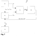
- the present invention has a calibration circuit 100, as described with reference to an embodiment in FIG Fig. 7 illustrates:
- the calibration circuit 100 according to Fig. 7 has two additional oscillators 30, 50 of substantially the same type as those described above with reference to FIG Fig. 4 described main oscillator 10 on.
- these two additional oscillators 30, 50 can be operated at a much lower frequency and thus with much lower power consumption than the main oscillator 10; however, these two additional oscillators 30, 50 have substantially the same tuning characteristics as the main oscillator 10.
- One of the two additional oscillators 30, 50 is a based Fig. 8
- the anodic terminal of a first varactor 52 of the calibration oscillator 50 is supplied with the first tuning voltage Vcm and the second tuning voltage Vcm-, and the anodic terminal of a second varactor 54 of the calibration oscillator 50 is supplied with the first tuning voltage Vcm and the third tuning voltage Vcm +.
- the cathodic terminal of the first varactor 52 and the cathodic terminal of the second varactor 54 are connected to one another, to the source contact or emitter terminal of a first transistor 62 of the calibration oscillator 50 and to the drain contact or collector terminal of a second transistor 64 of the calibration oscillator 50.
- the anodic terminal of a third varactor 56 of the calibration oscillator 50 is supplied with the first tuning voltage Vcm and the second tuning voltage Vcm-, and the anodic terminal of a fourth varactor 58 of the calibration oscillator 50 is supplied with the first tuning voltage Vcm and the third tuning voltage Vcm +.
- the cathodic terminal of the third varactor 56 and the cathodic terminal of the fourth varactor 58 are connected to each other, to the source contact or emitter terminal of a third transistor 66 of the calibration oscillator 50 and to the drain contact or collector terminal of a fourth transistor 68 of the calibration oscillator 50.
- the source contact or emitter terminal of the second transistor 64 and the source contact or emitter terminal of the fourth transistor 68 are connected to one another and to a current source 60 connected.
- the gate contact or base terminal of the first transistor 62 and the gate contact or base terminal of the third transistor 66 are connected to each other and are applied with a bias voltage or bias voltage Vbias.
- the drain contact or collector terminal of the first transistor 62 and the drain contact or collector terminal of the third transistor 66 provide the output signal Vc of the calibration oscillator 50.
- the other of the two additional oscillators 30, 50 is a based Fig. 9 Exemplary illustrated reference oscillator 30 which is associated with the calibration oscillator 50 in terms of timing.
- the anodic terminal of a first varactor 32 of the reference oscillator 30 and the anodic terminal of a second varactor 34 of the reference oscillator 30 are subjected to a reference potential or reference potential GND, namely ground potential or ground potential or zero potential.
- the cathodic terminal of the first varactor 32 and the cathodic terminal of the second varactor 34 are connected to one another, to the source contact or emitter terminal of a first transistor 42 of the reference oscillator 30 and to the drain contact or collector terminal of a second transistor 44 of the reference oscillator 30.
- the anodic terminal of a third varactor 36 of the reference oscillator 30 and the anodic terminal of a fourth varactor 38 of the reference oscillator 30 are supplied with the reference potential or reference potential GND, namely with ground potential or ground potential or zero potential.
- the cathodic terminal of the third varactor 36 and the cathodic terminal of the fourth varactor 38 are connected to one another, to the source contact or emitter terminal of a third transistor 46 of the reference oscillator 30 and to the drain contact or collector terminal of a fourth transistor 48 of the reference oscillator 30.
- the source contact or emitter terminal of the second transistor 44 and the source contact or emitter terminal of the fourth transistor 48 are connected to one another and to a current source 40.
- the gate contact or base terminal of the first transistor 42 and the gate contact or base terminal of the third transistor 46 are connected to each other and are applied with a bias voltage or bias voltage Vbias.
- the drain contact or collector terminal of the first transistor 42 and the drain contact or collector terminal of the third transistor 46 provide the output signal Vr of the reference oscillator 30.
- varactor diodes or tuning diodes or varicabs 12, 14, 32, 34, 36, 38, 52, 54, 56, 58 are electronic semiconductor devices in which a variation occurs by changing the applied voltage the capacity of for example 10 to 1 reach, so that an electrically controllable capacity is available.
- a portion of the aforementioned transistors 22, 24, 26, 28, 42, 44, 46, 48, 62, 64, 66, 68 may or all of the aforementioned transistors 22, 24, 26, 28, 42, 44, 46, 48, 62nd , 64, 66, 68 can be used, in particular, as field-effect transistors (FETs), for example as metal oxide semiconductor field-effect transistors (MOSFETs), such as n-type field effect transistors.
- MOSFETs metal oxide semiconductor field-effect transistors
- n-type MOSFETs may be formed.
- a clock counter 70 (so-called clock cycle error counter) connected downstream of the calibration oscillator 50 and the reference oscillator 30 compares the respective number N of clocks (clock cycles) of the calibration oscillator 50 on the basis of the output signal Vc of the calibration oscillator 50 and of the output signal Vr of the reference oscillator 30. of the reference oscillator 30 and forms the difference.
- N clock error DE (so-called clock cycle error) is integrated in the clock counter 70 and provided as a digital bus signal to the clock counter 70 subsequent digital-to-analog converter 90 as an input signal.
- the digital-to-analog converter 90 converts the clock error DE into an analog signal which sets the tuning voltage Vcm, Vcm-, Vcm + in the calibration oscillator 50 to the correct value.
- Fig. 10 exemplifies the calculations of the calibration circuit 100, in particular accuracy, standard deviation ⁇ , necessary counter length of the clock counter 70, bit width of the digital-to-analog converter 90 and the like.
Description
Die vorliegende Erfindung betrifft grundsätzlich das technische Gebiet des Ansteuerns mindestens eines spannungsgesteuerten Oszillators für Schaltungen zur Takt- und Datenrückgewinnung (= CDR = Clock and Data Recovery); im Spezielleren betrifft die vorliegende Erfindung eine Schaltungsanordnung gemäß dem Oberbegriff des Anspruchs 1 sowie ein Verfahren gemäß dem Oberbegriff des Anspruchs 13.The present invention generally relates to the technical field of driving at least one voltage-controlled oscillator for clock and data recovery circuits (= CDR = clock and data recovery); More specifically, the present invention relates to a circuit arrangement according to the preamble of
Bei derartigen Schaltungen zur Takt- und Datenrückgewinnung oder CDR-Schaltungen wird grundsätzlich die Art des Phasendetektors unterschieden:
- linearer Phasendetektor:
- die lineare Phasendifferenz an beiden Eingängen des Phasendetektors wird am Ausgang des Phasendetektors angezeigt;
- binärer Phasendetektor:
- am Ausgang des Phasendetektors wird das Vorzeichen der Phasendifferenz der beiden Eingänge des Phasendetektors ermittelt (voreilend oder nacheilend); dies kann zum Beispiel durch zwei digitale Phasendetektor-Ausgangssignale "up" (für voreilend) und "down" (für nacheilend) angezeigt werden oder aber durch ein Phasendetektor-Ausgangssignal, das drei verschiedene Ausgangspegel annehmen kann, zum Beispiel 200 Millivolt für voreilend, 400 Millivolt für Phasendifferenz gleich null und 600 Millivolt für nacheilend; charakteristisch für binäre Phasendetektoren ist, dass die Höhe der Ausgangsspannung keine Information über die aktuelle Phasendifferenz an den Eingängen des Phasendetektors liefert - es wird nur unterschieden zwischen Phasendifferenz kleiner null, Phasendifferenz gleich null, Phasendifferenz größer null.
- linear phase detector:
- the linear phase difference at both inputs of the phase detector is displayed at the output of the phase detector;
- binary phase detector:
- at the output of the phase detector, the sign of the phase difference of the two inputs of the phase detector is determined (leading or lagging); this may be indicated, for example, by two digital phase detector output signals "up" and "down", or by a phase detector output signal which may assume three different output levels, for example 200 millivolts leading, 400 Millivolts for phase difference equal to zero and 600 millivolts for lagging; characteristic of binary phase detectors is that the height of the output voltage provides no information about the current phase difference at the inputs of the phase detector - it is only distinguished between phase difference less than zero, phase difference equal to zero, phase difference greater than zero.
CDR-Schaltungen mit binären Phasendetektoren werden häufig bei Datenübertragungen im Frequenzbereich größer als ein Gigahertz eingesetzt, denn sie sind bei begrenzter Geschwindigkeit der verwendeten Technologie einfacher zu implementieren und zeigen ein sehr robustes Verhalten (bessere sogenannte Power-Supply-Rejection).CDR circuits with binary phase detectors are often used for data transmission in the frequency range greater than one gigahertz, because they are easier to implement at limited speed of the technology used and show a very robust behavior (better so-called power supply rejection).
Des Weiteren ist es bei der Implementierung von CDR-Schaltungen üblich, dass ein spannungsgesteuerter Oszillator (= VCO = Voltage-Controlled Oscillator) mit zwei Tuning-Eingängen eingesetzt wird, um im benötigten Schleifenfilter der CDR-Schaltung kleinere on-chip-Kapazitäten zu implementieren und des Weiteren das Phasenrauschen der CDR-Schaltung zu verbessern.Furthermore, in the implementation of CDR circuits, it is common to use a voltage controlled oscillator (= VCO = Voltage Controlled Oscillator) with two tuning inputs to provide smaller on-chip capacitances in the required loop filter of the CDR circuit and further improve the phase noise of the CDR circuit.
Mit den beiden digitalen Signalen up und dnb wird eine Feineinstellung des spannungsgesteuerten Oszillators RO' vorgenommen. up und dnb können die digitalen Ausgangssignale eines binären Phasendetektors sein.With the two digital signals up and dnb a fine adjustment of the voltage controlled oscillator RO 'is made. up and dnb can be the digital output signals of a binary phase detector.
- up = 0, dnb = 1: Ausgangsfrequenz f0;
- up = 1, dnb = 1: Ausgangsfrequenz f0 - df;
- up = 1, dnb = 0: Ausgangsfrequenz f0;
- up = 0, dnb = 0: Ausgangsfrequenz f0 + df.
- up = 0, dnb = 1: output frequency f0;
- up = 1, dnb = 1: output frequency f0 - df;
- up = 1, dnb = 0: output frequency f0;
- up = 0, dnb = 0: output frequency f0 + df.
Die Nachteile der gemäß den beiden Beispielen der
Die Druckschrift
Zum technologischen Hintergrund der vorliegenden Erfindung wird auf die Druckschrift
Ausgehend von den vorstehend dargelegten Nachteilen und Unzulänglichkeiten sowie unter Würdigung des umrissenen Standes der Technik liegt der vorliegenden Erfindung die Aufgabe zugrunde, eine Schaltungsanordnung gemäß dem Oberbegriff des Anspruchs 1 sowie ein Verfahren gemäß dem Oberbegriff des Anspruchs 13 so weiterzubilden, dass der Energieaufwand möglichst gering und die Ausgangsfrequenz möglichst groß ist.Based on the disadvantages and inadequacies set out above and in appreciation of the state of the art outlined, the present invention has the object, a circuit arrangement according to the preamble of
Diese Aufgabe wird durch eine Schaltungsanordnung mit den Merkmalen des Anspruchs 1 sowie durch ein Verfahren mit den Merkmalen des Anspruchs 13 gelöst. Vorteilhafte Ausgestaltungen und zweckmäßige Weiterbildungen der vorliegenden Erfindung sind in den jeweiligen Unteransprüchen gekennzeichnet.This object is achieved by a circuit arrangement having the features of
Erfindungsgemäß wird mindestens ein spannungsgesteuerter Oszillator (= VCO = Voltage-Controlled Oscillator) für mindestens eine Schaltung zur Takt- und Datenrückgewinnung (= CDR = Clock and Data Recovery), die mindestens einen binären Phasendetektor (= sogenannten Bang-Bang-Phasendetektor oder Aufwärts/Abwärts-Phasendetektor) aufweist, derart angesteuert, dass nicht mehr vier, sondern nur noch zwei Varaktor(diod)en oder Abstimmdioden oder Kapazitätsdioden oder Varicaps benötigt werden, wobei die Frequenzänderung nicht mehr mit zwei Ansteuersignalen, sondern nur noch mit einem Ansteuersignal erzielt wird.According to the invention, at least one voltage-controlled oscillator (= VCO = Voltage-Controlled Oscillator) for at least one circuit for clock and data recovery (CDR = Clock and Data Recovery), the at least one binary phase detector (= so-called Bang-Bang phase detector or up / Down phase detector), so controlled that no longer four, but only two varactor (diod) s or tuning diodes or varactor diodes or varicaps are needed, the frequency change is no longer achieved with two drive signals, but only with a drive signal.
Hierdurch ist zum einen ein niedriger Strombedarf, das heißt ein niedriger Energieverbrauch realisierbar, denn aufgrund geringerer Parasitär-Kapazität als im Stand der Technik ist weniger Strom erforderlich, um die gleiche Ausgangsfrequenz zu erzielen. Zum anderen ist eine höhere Ausgangsfrequenz realisierbar, denn durch lediglich zwei Varaktoren (anstelle vierer Varaktoren im Stand der Technik) wird weniger parasitäre Kapazität im spannungsgesteuerten Oszillator erzeugt, so dass das Layout des spannungsgesteuerten Oszillators kompakter gestaltet werden kann.As a result, on the one hand, a low power consumption, that is, a low energy consumption feasible, because due to lower parasitic capacity than in the prior art less power is required to achieve the same output frequency. On the other hand, a higher output frequency is feasible, because only two varactors (instead of four varactors in the prior art) less parasitic capacitance is generated in the voltage controlled oscillator, so that the layout of the voltage controlled oscillator can be made more compact.
Die vorliegende Erfindung betrifft schließlich die Verwendung mindestens einer Schaltungsanordnung gemäß der vorstehend dargelegten Art und/oder eines Verfahrens gemäß der vorstehend dargelegten Art zum Ansteuern mindestens eines spannungsgesteuerten Oszillators (= VCO = Voltage-Controlled Oscillator) für mindestens eine Schaltung zur Takt- und Datenrückgewinnung (= CDR = Clock and Data Recovery) mit mindestens einem binären Phasendetektor (= sogenannter Bang-Bang-Phasendetektor oder Aufwärts/Abwärts-Phasendetektor).Finally, the present invention relates to the use of at least one circuit arrangement according to the above-described type and / or a method according to the above-described type for driving at least one voltage-controlled oscillator (= VCO = Voltage-Controlled Oscillator) for at least one circuit for clock and data recovery ( = CDR = clock and data recovery) with at least one binary phase detector (= so-called bang-bang phase detector or up / down phase detector).
Wie bereits vorstehend erörtert, gibt es verschiedene Möglichkeiten, die Lehre der vorliegenden Erfindung in vorteilhafter Weise auszugestalten und weiterzubilden. Hierzu wird einerseits auf die dem Anspruch 1 sowie dem Anspruch 13 nachgeordneten Ansprüche verwiesen, andererseits werden weitere Ausgestaltungen, Merkmale und Vorteile der vorliegenden Erfindung nachstehend unter Anderem anhand des durch
- Fig. 1
- in konzeptuell-schematischer Darstellung ein erstes Beispiel für einen spannungsgesteuerten Oszillator aus dem Stand der Technik, der nach dem Verfahren aus dem Stand der Technik arbeitet;
- Fig. 2
- in konzeptuell-schematischer Darstellung ein zweites Beispiel für einen spannungsgesteuerten Oszillator aus dem Stand der Technik, der nach dem Verfahren aus dem Stand der Technik arbeitet;
- Fig.3
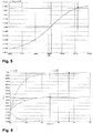
- in diagrammatischer Darstellung die typische Frequenz-Tuning-Charakteristik des spannungsgesteuerten Oszillators aus
Fig. 2 , wobei die Ansteuerspannung auf der Rechtsachse aufgetragen ist; - Fig. 4
- in konzeptuell-schematischer Darstellung ein Ausführungsbeispiel für einen spannungsgesteuerten Oszillator, der Teil der erfindungsgemäßen Schaltungsanordnung aus
Fig. 7 ist und nach dem Verfahren gemäß der vorliegenden Erfindung arbeitet; - Fig. 5
- in diagrammatischer Darstellung die Frequenz-Tuning-Charakteristik des spannungsgesteuerten Oszillators aus
Fig. 4 , wobei die Ansteuerspannung auf der Rechtsachse aufgetragen ist; - Fig. 6
- in diagrammatischer Darstellung betriebsparameterbedingte Abweichungen in der Frequenz-Tuning-Charakteristik aus
Fig. 5 ; - Fig. 7
- in konzeptuell-schematischer Darstellung ein Ausführungsbeispiel für eine Schaltungsanordnung gemäß der vorliegenden Erfindung, die nach dem Verfahren gemäß der vorliegenden Erfindung arbeitet;
- Fig.8
- in konzeptuell-schematischer Darstellung ein Ausführungsbeispiel für einen Kalibrierungsoszillator, der Teil der erfindungsgemäßen Schaltungsanordnung aus
Fig. 7 ist und nach dem Verfahren gemäß der vorliegenden Erfindung arbeitet; - Fig. 9
- in konzeptuell-schematischer Darstellung ein Ausführungsbeispiel für einen Referenzoszillator, der Teil der erfindungsgemäßen Schaltungsanordnung aus
Fig. 7 ist und nach dem Verfahren gemäß der vorliegenden Erfindung arbeitet; und - Fig. 10
- in diagrammatischer Darstellung eine visuelle Veranschaulichung der Berechnungen der Schaltungsanordnung aus
Fig. 7 .
- Fig. 1
- in conceptual schematic representation of a first example of a voltage-controlled oscillator of the prior art, according to the method of the prior art is working;
- Fig. 2
- in conceptual schematic representation of a second example of a voltage-controlled oscillator of the prior art, which operates according to the method of the prior art;
- Figure 3
- in diagrammatic representation of the typical frequency-tuning characteristic of the voltage controlled oscillator
Fig. 2 wherein the drive voltage is plotted on the right axis; - Fig. 4
- in conceptual-schematic representation of an embodiment of a voltage controlled oscillator, the part of the circuit arrangement according to the invention
Fig. 7 is and operates according to the method according to the present invention; - Fig. 5
- in diagrammatic representation of the frequency-tuning characteristic of the voltage controlled oscillator
Fig. 4 wherein the drive voltage is plotted on the right axis; - Fig. 6
- in diagrammatic representation, operating-parameter-related deviations in the frequency tuning characteristic
Fig. 5 ; - Fig. 7
- in conceptual schematic representation of an embodiment of a circuit arrangement according to the present invention, which operates according to the method according to the present invention;
- Figure 8
- in conceptual-schematic representation of an embodiment of a calibration oscillator, the part of the circuit arrangement according to the invention
Fig. 7 is and operates according to the method according to the present invention; - Fig. 9
- in conceptual-schematic representation of an embodiment of a reference oscillator, the part of the circuit arrangement according to the invention
Fig. 7 is and operates according to the method according to the present invention; and - Fig. 10
- in diagrammatic representation, a visual illustration of the calculations of the circuit arrangement
Fig. 7 ,
Gleiche oder ähnliche Ausgestaltungen, Elemente oder Merkmale sind in
Der kathodische Anschluss des ersten Varaktors 12 ist mit dem Sourcekontakt oder Emitteranschluss eines ersten Transistors 22 des spannungsgesteuerten Oszillators 10 sowie mit dem Drainkontakt oder Kollektoranschluss eines zweiten Transistors 24 des spannungsgesteuerten Oszillators 10 verbunden, und der kathodische Anschluss des zweiten Varaktors 14 ist mit dem Sourcekontakt oder Emitteranschluss eines dritten Transistors 26 des spannungsgesteuerten Oszillators 10 sowie mit dem Drainkontakt oder Kollektoranschluss eines vierten Transistors 28 des spannungsgesteuerten Oszillators 10 verbunden.The cathodic terminal of the
Der Sourcekontakt oder Emitteranschluss des zweiten Transistors 24 und der Sourcekontakt oder Emitteranschluss des vierten Transistors 28 sind miteinander sowie mit einer Stromquelle 20 verbunden. Der Gatekontakt oder Basisanschluss des ersten Transistors 22 und der Gatekontakt oder Basisanschluss des dritten Transistors 26 sind miteinander verbunden und werden mit einer Biasspannung oder Vorspannung Vbias beaufschlagt. Der Drainkontakt oder Kollektoranschluss des ersten Transistors 22 und der Drainkontakt oder Kollektoranschluss des dritten Transistors 26 stellen das Ausgangssignal Ve des spannungsgesteuerten Oszillators 10 zur Verfügung.The source contact or emitter terminal of the
- Tuningspannung Vbb = 200 Millivolt --> Ausgangsfrequenz f0 - df;
- Tuningspannung Vbb = 400 Millivolt --> Ausgangsfrequenz f0;
- Tuningspannung Vbb = 600 Millivolt --> Ausgangsfrequenz f0 + df.
- Tuning voltage Vbb = 200 millivolts -> output frequency f0 - df;
- Tuning voltage Vbb = 400 millivolts -> output frequency f0;
- Tuning voltage Vbb = 600 millivolts -> output frequency f0 + df.
Die Frequenz-Tuning-Charakteristik ändert sich über die Betriebsparameter, wie etwa Technologie, Versorgungsspannung und Temperatur. Dieses Verhalten ist in
Um nun für alle Betriebsparameter jeweils die korrekte Tuningspannung Vbb zu erzeugen, weist die vorliegende Erfindung eine Kalibrierungsschaltung 100 auf, wie anhand eines Ausführungsbeispiels in
Die Kalibrierungsschaltung 100 gemäß
Der eine der beiden zusätzlichen Oszillatoren 30, 50 ist ein anhand
Der anodische Anschluss eines ersten Varaktors 52 des Kalibrierungsoszillators 50 wird mit der ersten Tuningspannung Vcm und mit der zweiten Tuningspannung Vcm- beaufschlagt, und der anodische Anschluss eines zweiten Varaktors 54 des Kalibrierungsoszillators 50 wird mit der ersten Tuningspannung Vcm und mit der dritten Tuningspannung Vcm+ beaufschlagt.The anodic terminal of a
Der kathodische Anschluss des ersten Varaktors 52 und der kathodische Anschluss des zweiten Varaktors 54 sind miteinander, mit dem Sourcekontakt oder Emitteranschluss eines ersten Transistors 62 des Kalibrierungsoszillators 50 sowie mit dem Drainkontakt oder Kollektoranschluss eines zweiten Transistors 64 des Kalibrierungsoszillators 50 verbunden.The cathodic terminal of the
Der anodische Anschluss eines dritten Varaktors 56 des Kalibrierungsoszillators 50 wird mit der ersten Tuningspannung Vcm und mit der zweiten Tuningspannung Vcm- beaufschlagt, und der anodische Anschluss eines vierten Varaktors 58 des Kalibrierungsoszillators 50 wird mit der ersten Tuningspannung Vcm und mit der dritten Tuningspannung Vcm+ beaufschlagt.The anodic terminal of a
Der kathodische Anschluss des dritten Varaktors 56 und der kathodische Anschluss des vierten Varaktors 58 sind miteinander, mit dem Sourcekontakt oder Emitteranschluss eines dritten Transistors 66 des Kalibrierungsoszillators 50 sowie mit dem Drainkontakt oder Kollektoranschluss eines vierten Transistors 68 des Kalibrierungsoszillators 50 verbunden.The cathodic terminal of the
Der Sourcekontakt oder Emitteranschluss des zweiten Transistors 64 und der Sourcekontakt oder Emitteranschluss des vierten Transistors 68 sind miteinander sowie mit einer Stromquelle 60 verbunden. Der Gatekontakt oder Basisanschluss des ersten Transistors 62 und der Gatekontakt oder Basisanschluss des dritten Transistors 66 sind miteinander verbunden und werden mit einer Biasspannung oder Vorspannung Vbias beaufschlagt. Der Draihkontakt oder Kollektoranschluss des ersten Transistors 62 und der Drainkontakt oder Kollektoranschluss des dritten Transistors 66 stellen das Ausgangssignal Vc des Kalibrierungsoszillators 50 zur Verfügung.The source contact or emitter terminal of the
Der anderen der beiden zusätzlichen Oszillatoren 30, 50 ist ein anhand
Der anodische Anschluss eines ersten Varaktors 32 des Referenzoszillators 30 und der anodische Anschluss eines zweiten Varaktors 34 des Referenzoszillators 30 werden mit einem Bezugspotential oder Referenzpotential GND, nämlich mit Erdpotential oder Massepotential oder Nullpotential beaufschlagt.The anodic terminal of a
Der kathodische Anschluss des ersten Varaktors 32 und der kathodische Anschluss des zweiten Varaktors 34 sind miteinander, mit dem Sourcekontakt oder Emitteranschluss eines ersten Transistors 42 des Referenzoszillators 30 sowie mit dem Drainkontakt oder Kollektoranschluss eines zweiten Transistors 44 des Referenzoszillators 30 verbunden.The cathodic terminal of the
Der anodische Anschluss eines dritten Varaktors 36 des Referenzoszillators 30 und der anodische Anschluss eines vierten Varaktors 38 des Referenzoszillators 30 werden mit dem Bezugspotential oder Referenzpotential GND, nämlich mit Erdpotential oder Massepotential oder Nullpotential beaufschlagt.The anodic terminal of a third varactor 36 of the
Der kathodische Anschluss des dritten Varaktors 36 und der kathodische Anschluss des vierten Varaktors 38 sind miteinander, mit dem Sourcekontakt oder Emitteranschluss eines dritten Transistors 46 des Referenzoszillators 30 sowie mit dem Drainkontakt oder Kollektoranschluss eines vierten Transistors 48 des Referenzoszillators 30 verbunden.The cathodic terminal of the third varactor 36 and the cathodic terminal of the
Der Sourcekontakt oder Emitteranschluss des zweiten Transistors 44 und der Sourcekontakt oder Emitteranschluss des vierten Transistors 48 sind miteinander sowie mit einer Stromquelle 40 verbunden. Der Gatekontakt oder Basisanschluss des ersten Transistors 42 und der Gatekontakt oder Basisanschluss des dritten Transistors 46 sind miteinander verbunden und werden mit einer Biasspannung oder Vorspannung Vbias beaufschlagt. Der Drainkontakt oder Kollektoranschluss des ersten Transistors 42 und der Drainkontakt oder Kollektoranschluss des dritten Transistors 46 stellen das Ausgangssignal Vr des Referenzoszillators 30 zur Verfügung.The source contact or emitter terminal of the
Bei den vorgenannten Varaktor(diod)en oder Abstimmdioden oder Kapazitätsdioden oder Varicaps 12, 14, 32, 34, 36, 38, 52, 54, 56, 58 handelt es sich um elektronische Halbleiterbauteile, bei denen sich durch Ändern der angelegten Spannung eine Variation der Kapazität von zum Beispiel 10 zu 1 erreichen lässt, so dass eine elektrisch steuerbare Kapazität zur Verfügung steht.The aforementioned varactor diodes or tuning diodes or
Ein Teil der vorgenannten Transistoren 22, 24, 26, 28, 42, 44, 46, 48, 62, 64, 66, 68 kann oder alle vorgenannten Transistoren 22, 24, 26, 28, 42, 44, 46, 48, 62, 64, 66, 68 können insbesondere als Feldeffekttransistoren (FET = Field-Effect Transistor), zum Beispiel als Metall-Oxid-Halbleiter-Feldeffekttransistoren (MOSFET = Metal-Oxide-Semiconductor Field-Effect Transistor), wie etwa als n-Typ-Metall-Oxid-Halbleiter-Feldeffekttransistoren (n-type MOSFETs), ausgebildet sein.A portion of the
Ein dem Kalibrierungsoszillator 50 sowie dem Referenzoszillator 30 nachgeschalteter Taktzähler 70 (sogenannter clock cycle error counter) vergleicht auf Basis des Ausgangssignals Vc des Kalibrierungsoszillators 50 sowie des Ausgangssignals Vr des Referenzoszillators 30 die jeweilige Anzahl N der Takte (sogenannte clock cycles) des Kalibrierungsoszillators 50 bzw. des Referenzoszillators 30 und bildet die Differenz.A clock counter 70 (so-called clock cycle error counter) connected downstream of the
Der sich aus der Differenz dieser beiden Taktanzahlen N ergebende Taktfehler DE (sogenannter clock cycle error) wird im Taktzähler 70 integriert und als digitales Bus-Signal einem dem Taktzähler 70 nachfolgenden Digital-Analog-Wandler 90 als Eingangssignal bereit gestellt. Der Digital-Analog-Wandler 90 wandelt den Taktfehler DE in ein analoges Signal um, das die Tuningspannung Vcm, Vcm-, Vcm+ im Kalibrierungsoszillator 50 auf den richtigen Wert einstellt.The resulting from the difference of these two clock numbers N clock error DE (so-called clock cycle error) is integrated in the
-
ist in der obersten Zeile der
Fig. 10 die jeweils durch einen Doppelpfeil angedeutete zeitliche Signallänge N*Tref± σref*N0,5 veranschaulicht,is in the top line of theFig. 10 the time signal length N * T ref ± σ ref * N 0.5 indicated in each case by a double arrow illustrates -
in der zweitobersten Zeile wird die Funktion des N Zyklen zählenden Referenzoszillators 30 veranschaulicht,the second-highest line illustrates the function of the N-
cycle reference oscillator 30, -
in der zweituntersten Zeile wird die Funktion des die Frequenz verschiebenden Kalibrierungsoszillators 50 veranschaulicht undin the second lower line the function of the frequency shifting
calibration oscillator 50 is illustrated and -
in der untersten Zeile wird die Funktion des digitalen Integrierers innerhalb des Taktzählers 70 veranschaulicht.in the bottom line, the function of the digital integrator within the
clock counter 70 is illustrated.
Hierbei ergibt sich die Anzahl Ncount@600 der clock cycles (Takte) während der Tuningspannung Vcm + 200 Millivolt (= etwa 600 Millivolt) zu Ncount@600 = [N*Tref ± σref*N0,5 ± σ600*(N*Tref/T600)0,5]T600; entsprechend ergibt sich die Anzahl Ncount@400 der clock cycles (Takte) während der Tuningspannung Vcm (= etwa 400 Millivolt) zu Ncount@400 = [N*Tref 2 ± σref*N0,5 ±σ400*(N*Tref/T400)0,5]/T400, und die Anzahl Ncount@200 der clock cycles (Takte) während der Tuningspannung Vcm - 200 Millivolt (= etwa 200 Millivolt) ergibt sich zu Ncount@200 = [N*Tref ± σref*N0,5 ± σ200*(N*Tref/T200)0,5]/T200.This results in the number N count @ 600 of the clock cycles (clocks) during the tuning voltage Vcm + 200 millivolts (= about 600 millivolts) to N count @ 600 = [N * T ref ± σ ref * N 0.5 ± σ 600 * (N * T ref / T 600 ) 0.5 ] T 600 ; Correspondingly, the number N count @ 400 of the clock cycles (cycles) during the tuning voltage Vcm (= approximately 400 millivolts) results in N count @ 400 = [N * T ref 2 ± σ ref * N 0.5 ± σ 400 * ( N * T ref / T 400 ) 0.5 ] / T 400 , and the number N count @ 200 of the clock cycles (clocks) during the tuning voltage Vcm - 200 millivolts (= about 200 millivolts) results to N count @ 200 = [N * T ref ± σ ref * N 0.5 ± σ 200 * (N * T ref / T 200 ) 0.5 ] / T 200 .
Wenn der Referenzoszillator 30 von derselben Art wie der Kalibrierungsoszillator 50 ist, so ist auch die Jitter-Performance dieselbe, so dass in obiger Formel σ600*(N*Tref/T600)0,5 = σref*N0,5 bzw. σ400*(N*Tref/T400)0,5 = σref*N0,5 bzw. σ200*(N*Tref/T200)0,5 = σref*N0,5 gilt.If the
In diesem Falle ergibt sich die Anzahl Ncount@600 der clock cycles (Takte) während der Tuningspannung Vcm + 200 Millivolt (= etwa 600 Millivolt) zu Anzahl Ncount@600 = [N*Tref ± 2*σref*N0,5]/T600; entsprechend ergibt sich die Anzahl Ncount@400 der clock cycles (Takte) während der Tuningspannung Vcm (= etwa 400 Millivolt) zu Anzahl Ncount@400 = [N*Tref ± 2*σref*N0,5]/T400, und die Anzahl Ncount@200 der clock cycles (Takte) während der Tuningspannung Vcm - 200 Millivolt (= etwa 200 Millivolt) ergibt sich zu zu Anzahl Ncount@200 = [N*Tref ± 2*σref*N0,5]/T200.In this case, the number N count @ 600 of the clock cycles (clocks) during the tuning voltage Vcm + 200 millivolts (= about 600 millivolts) results in the number N count @ 600 = [N * T ref ± 2 * σ ref * N 0 , 5 ] / T 600 ; Correspondingly, the number N count @ 400 of the clock cycles (cycles) during the tuning voltage Vcm (= approximately 400 millivolts) results in the number N count @ 400 = [N * T ref ± 2 * σ ref * N 0.5 ] / T 400 , and the number N count @ 200 of the clock cycles (clocks) during the tuning voltage Vcm - 200 millivolts (= about 200 millivolts) results in number N count @ 200 = [N * T ref ± 2 * σ ref * N 0.5 ] / T 200 .
Der digitale Integrierer innerhalb des Taktzählers 70 gibt unter Berücksichtigung des digitalen Fehlers DE die Gesamtanzahl Ncount@600 - Ncount@400 + Ncount@200 - Ncount@400 = [N*Tref ± 2*σref*N0,5]/T600 - [N*Tref ± 2*σref*N0,5]/T400 + [N*Tref ± 2*σref*N0,5]/T200 - [N*Tref ± 2*σref*N0,5]/T400 aus.The digital integrator within the
Da nun ± 2*σref*N0,5]/T600 ± 2*σref*N0,5]/T400 ± 2*σref*N0,5]/T200 ± 2*σref*N0,5]/T400 = ± 8*σref*N0,5]/T400, ergibt sich eine Frequenzabweichung Δf600-400 - Δf400-200 = 1/T600 - 1/T400 - (1/T400 - 1/T200) = 1/T600 - 1/T400 + 1/T200 - 1/T400 = ± 8*σref/Tref*T400*N0,5).Now that ± 2 * σ ref * N 0.5 ] / T 600 ± 2 * σ ref * N 0.5 ] / T 400 ± 2 * σ ref * N 0.5 ] / T 200 ± 2 * σ ref * N 0.5 ] / T 400 = ± 8 * σ ref * N 0.5 ] / T 400 , there is a frequency deviation Δf 600-400 - Δf 400-200 = 1 / T 600 - 1 / T 400 - (1 / T 400 - 1 / T 200 ) = 1 / T 600 - 1 / T 400 + 1 / T 200 - 1 / T 400 = ± 8 * σ ref / T ref * T 400 * N 0.5 ).
- 100100
- Schaltungsanordnung, insbesondere KalibrierungsschaltungCircuit arrangement, in particular calibration circuit
- 1010
- spannungsgesteuerter Oszillator, insbesondere spannungsgesteuerter Ringoszillatorvoltage-controlled oscillator, in particular voltage-controlled ring oscillator
- 1212
-
erster Varaktor des spannungsgesteuerten Oszillators 10first varactor of the voltage-controlled
oscillator 10 - 1414
-
zweiter Varaktor des spannungsgesteuerten Oszillators 10second varactor of the voltage-controlled
oscillator 10 - 2020
- Stromquelle des spannungsgesteuerten Oszillators 10Current source of the voltage controlled oscillator 10th
- 2222
-
erster Transistor des spannungsgesteuerten Oszillators 10first transistor of the voltage-controlled
oscillator 10 - 2424
- zweiter Transistor des spannungsgesteuerten Oszillators 10second transistor of the voltage controlled oscillator 10th
- 2626
-
dritter Transistor des spannungsgesteuerten Oszillators 10third transistor of the voltage-controlled
oscillator 10 - 2828
-
vierter Transistor des spannungsgesteuerten Oszillators 10fourth transistor of the voltage controlled
oscillator 10 - 3030
- Referenzoszillatorreference oscillator
- 3232
-
erster Varaktor des Referenzoszillators 30first varactor of the
reference oscillator 30 - 3434
-
zweiter Varaktor des Referenzoszillators 30second varactor of the
reference oscillator 30 - 3636
-
dritter Varaktor des Referenzoszillators 30third varactor of the
reference oscillator 30 - 3838
-
vierter Varaktor des Referenzoszillators 30fourth varactor of the
reference oscillator 30 - 4040
-
Stromquelle des Referenzoszillators 30Current source of the
reference oscillator 30 - 4242
-
erster Transistor des Referenzoszillators 30first transistor of the
reference oscillator 30 - 4444
- zweiter Transistor des Referenzoszillators 30second transistor of the reference oscillator 30th
- 4646
- dritter Transistor des Referenzoszillators 30third transistor of the reference oscillator 30th
- 4848
-
vierter Transistor des Referenzoszillators 30fourth transistor of the
reference oscillator 30 - 5050
- Kalibrierungsoszillatorcalibration oscillator
- 5252
-
erster Varaktor des Kalibrierungsoszillators 50first varactor of the
calibration oscillator 50 - 5454
-
zweiter Varaktor des Kalibrierungsoszillators 50second varactor of the
calibration oscillator 50 - 5656
-
dritter Varaktor des Kalibrierungsoszillators 50third varactor of the
calibration oscillator 50 - 5858
-
vierter Varaktor des Kalibrierungsoszillators 50fourth varactor of the
calibration oscillator 50 - 6060
-
Stromquelle des Kalibrierungsoszillators 50Current source of the
calibration oscillator 50 - 6262
-
erster Transistor des Kalibrierungsoszillators 50first transistor of the
calibration oscillator 50 - 6464
-
zweiter Transistor des Kalibrierungsoszillators 50second transistor of the
calibration oscillator 50 - 6666
-
dritter Transistor des Kalibrierungsoszillators 50third transistor of the
calibration oscillator 50 - 6868
-
vierter Transistor des Kalibrierungsoszillators 50fourth transistor of the
calibration oscillator 50 - 7070
- Taktzählerclock counter
- 9090
- Digital-Analog-WandlerDigital to analog converter
- D1D1
-
erster Varaktor des spannungsgesteuerten Oszillators RO (= Stand der Technik; vgl.
Fig. 1 )first varactor of the voltage-controlled oscillator RO (= state of the art;Fig. 1 ) - D1'D1 '
-
erster Varaktor des spannungsgesteuerten Oszillators RO' (= Stand der Technik; vgl.
Fig. 2 )first varactor of the voltage-controlled oscillator RO '(= prior art;Fig. 2 ) - D2D2
-
zweiter Varaktor des spannungsgesteuerten Oszillators RO (= Stand der Technik; vgl.
Fig. 1 )second varactor of the voltage controlled oscillator RO (= prior art;Fig. 1 ) - D2'D2 '
-
zweiter Varaktor des spannungsgesteuerten Oszillators RO' (= Stand der Technik; vgl.
Fig. 2 )second varactor of the voltage-controlled oscillator RO '(= prior art;Fig. 2 ) - D3D3
-
dritter Varaktor des spannungsgesteuerten Oszillators RO (= Stand der Technik; vgl.
Fig. 1 )third varactor of the voltage-controlled oscillator RO (= state of the art;Fig. 1 ) - D3'D3 '
-
dritter Varaktor des spannungsgesteuerten Oszillators RO' (= Stand der Technik; vgl.
Fig. 2 )third varactor of the voltage-controlled oscillator RO '(= prior art;Fig. 2 ) - D4D4
-
vierter Varaktor des spannungsgesteuerten Oszillators RO (= Stand der Technik; vgl.
Fig. 1 )fourth varactor of the voltage-controlled oscillator RO (= prior art;Fig. 1 ) - D4'D4 '
-
vierter Varaktor des spannungsgesteuerten Oszillators RO' (= Stand der Technik; vgl.
Fig. 2 )fourth varactor of the voltage-controlled oscillator RO '(= prior art;Fig. 2 ) - DEDE
- Taktfehler, insbesondere digitaler TaktfehlerClock error, especially digital clock error
- dnbdnb
-
zweites digitales Signal zur Feineinstellung des spannungsgesteuerten Oszillators RO' (= Stand der Technik; vgl.
Fig. 2 )second digital signal for fine adjustment of the voltage-controlled oscillator RO '(= prior art;Fig. 2 ) - GNDGND
- Bezugspotential oder Referenzpotential, insbesondere Erdpotential oder Massepotential oder NullpotentialReference potential or reference potential, in particular ground potential or ground potential or zero potential
- I1I1
-
Stromstärke der ersten Stromquelle SQ1' (= Stand der Technik; vgl.
Fig. 2 )Amperage of the first current source SQ1 '(= state of the art;Fig. 2 ) - I2I2
-
Stromstärke der zweiten Stromquelle SQ2' (= Stand der Technik; vgl.
Fig. 2 )Amperage of the second current source SQ2 '(= prior art;Fig. 2 ) - NN
- Taktanzahlnumber of measures
- RORO
-
spannungsgesteuerter Oszillator, insbesondere spannungsgesteuerter Ringoszillator (= Stand der Technik; vgl.
Fig. 1 )voltage-controlled oscillator, in particular voltage-controlled ring oscillator (= state of the art;Fig. 1 ) - RO'RO '
-
spannungsgesteuerter Oszillator, insbesondere spannungsgesteuerter Ringoszillator (= Stand der Technik; vgl.
Fig. 2 )voltage-controlled oscillator, in particular voltage-controlled ring oscillator (= state of the art;Fig. 2 ) - SQSQ
-
Stromquelle des spannungsgesteuerten Oszillators RO (= Stand der Technik; vgl.
Fig. 1 )Current source of the voltage-controlled oscillator RO (= prior art;Fig. 1 ) - SQ1'SQ1 '
-
erste Stromquelle des spannungsgesteuerten Oszillators RO' (= Stand der Technik; vgl.
Fig. 2 )first current source of the voltage-controlled oscillator RO '(= prior art;Fig. 2 ) - SQ2'SQ2 '
-
zweite Stromquelle des spannungsgesteuerten Oszillators RO' (= Stand der Technik; vgl.
Fig. 2 )second current source of the voltage-controlled oscillator RO '(= prior art;Fig. 2 ) - TrefTref
- Zeit oder ZeitspanneTime or period of time
- T1T1
-
erster Transistor des spannungsgesteuerten Oszillators RO (= Stand der Technik; vgl.
Fig. 1 )first transistor of the voltage-controlled oscillator RO (= prior art;Fig. 1 ) - T1'T1 '
-
erster Transistor des spannungsgesteuerten Oszillators RO' (= Stand der Technik; vgl.
Fig. 2 )first transistor of the voltage-controlled oscillator RO '(= prior art;Fig. 2 ) - T2T2
-
zweiter Transistor des spannungsgesteuerten Oszillators RO (= Stand der Technik; vgl.
Fig. 1 )second transistor of the voltage-controlled oscillator RO (= prior art;Fig. 1 ) - T2'T2 '
-
zweiter Transistor des spannungsgesteuerten Oszillators RO' (= Stand der Technik; vgl.
Fig. 2 )second transistor of the voltage-controlled oscillator RO '(= prior art;Fig. 2 ) - T3T3
-
dritter Transistor des spannungsgesteuerten Oszillators RO (= Stand der Technik; vgl.
Fig. 1 )third transistor of the voltage-controlled oscillator RO (= prior art;Fig. 1 ) - T3'T3 '
-
dritter Transistor des spannungsgesteuerten Oszillators RO' (= Stand der Technik; vgl.
Fig. 2 )third transistor of the voltage-controlled oscillator RO '(= prior art;Fig. 2 ) - T4T4
-
vierter Transistor des spannungsgesteuerten Oszillators RO (= Stand der Technik; vgl.
Fig. 1 )fourth transistor of the voltage-controlled oscillator RO (= prior art;Fig. 1 ) - T4'T4 '
-
vierter Transistor des spannungsgesteuerten Oszillators RO' (= Stand der Technik; vgl.
Fig. 2 )fourth transistor of the voltage-controlled oscillator RO '(= prior art;Fig. 2 ) - T5'T5 '
-
fünfter Transistor des spannungsgesteuerten Oszillators RO' (= Stand der Technik; vgl.
Fig. 2 )fifth transistor of the voltage-controlled oscillator RO '(= prior art;Fig. 2 ) - T6'T6 '
-
sechster Transistor des spannungsgesteuerten Oszillators RO' (= Stand der Technik; vgl.
Fig. 2 )sixth transistor of the voltage-controlled oscillator RO '(= prior art;Fig. 2 ) - upup
-
erstes digitales Signal zur Feineinstellung des spannungsgesteuerten Oszillators RO' (= Stand der Technik; vgl.
Fig. 2 )first digital signal for fine adjustment of the voltage-controlled oscillator RO '(= prior art;Fig. 2 ) - VbbVbb
- Ansteuersignal des spannungsgesteuerten Oszillators 10Drive signal of the voltage controlled oscillator 10th
- VbiasV bias
- Biasspannung oder VorspannungBias voltage or bias voltage
- VcVc
-
Ausgangssignal des Kalibrierungsoszillators 50Output signal of the
calibration oscillator 50 - VcmVcm
-
erstes Tuningsignal des Kalibrierungsoszillators 50first tuning signal of the
calibration oscillator 50 - Vcm-VCM
-
zweites Tuningsignal des Kalibrierungsoszillators 50second tuning signal of the
calibration oscillator 50 - Vcm+Vcm +
-
drittes Tuningsignal des Kalibrierungsoszillators 50third tuning signal of the
calibration oscillator 50 - VeVe
-
Ausgangssignal des spannungsgesteuerten Oszillators 10Output signal of the voltage-controlled
oscillator 10 - VrVr
-
Ausgangssignal des Referenzoszillators 30Output signal of the
reference oscillator 30 - Vtune1Vtune1
-
erster Tuning-Eingang (= Stand der Technik; vgl.
Fig. 1 undFig. 2 )first tuning input (= state of the art;Fig. 1 andFig. 2 ) - Vtune2Vtune2
-
zweiter Tuning-Eingang (= Stand der Technik; vgl.
Fig. 1 )second tuning input (= state of the art;Fig. 1 )
Claims (15)
- A circuit arrangement (100) for calibrating at least one activation signal (Vbb) provided for a voltage-controlled oscillator (10),
characterized by- at least one calibration oscillator (50),- at least one reference oscillator (30) associated with the calibration oscillator (50),- at least one clock counter (70) arranged downstream of the calibration oscillator (50) and the reference oscillator (30) for counting the respective number of clock cycles (N) of the calibration oscillator (50) and the reference oscillator (30) as well as for integrating a clock error (DE) resulting from the difference between these two clock cycles (N), and- at least one digital/analogue converter (90) arranged downstream of the clock counter (70) for converting the clock error (DE) into analogue tuning signals (Vcm, Vcm-, Vcm+), from which the calibrated activation signal (Vbb) can be derived. - The circuit arrangement according to claim 1, characterized in that the voltage-controlled oscillator (10) comprises:- a first varactor (12), the cathodic connection of which is connected with the source contact or emitter connection of a first transistor (22) as well as with the drain contact or collector connection of a second transistor (24), and- a second varactor (14), the cathode connection of which is connected with the source contact or emitter connection of a third transistor (26) as well as with the drain contact or collector connection of a fourth transistor (28).
- The circuit arrangement according to claim 2, characterized in that the source contact or emitter connection of the second transistor (24) and the source contact or emitter connection of the fourth transistor (28) are connected with each other as well as with at least one current source (20).
- The circuit arrangement according to claim 2 or 3, characterized in- that the gate contact or basis connection of the first transistor (22) and the gate contact or basis connection of the third transistor (26) are connected with each other and that a bias voltage (Vbias) can be applied to them, and- that the drain contact or collector connection of the first transistor (22) and the drain contact or collector connection of the third transistor (26) provide the output signal (Ve) of the voltage-controlled oscillator (10).
- The circuit arrangement according to at least one of claims 2 to 4, characterized in that the calibrated activation signal (Vbb) may be applied to the anodic connection of the first varactor (12) of the voltage-controlled oscillator (10) and to the anodic connection of the second varactor (14) of the voltage-controlled oscillator (10).
- The circuit arrangement according to at least one of claims 1 to 5 characterized in that the reference oscillator (30) comprises:- a first varactor (32), to the anodic connection of which a reference potential (GND), in particular earth potential or ground potential or zero potential may be applied, as well as- a second varactor (34), to the anodic connection of which the reference potential (GND) may be applied,
wherein the cathodic connection of the first varactor (32) and the cathodic connection of the second varactor (34) are connected with each other, with the source contact or emitter connection of a first transistor (42) as well as with the drain contact or collector connection of a second transistor (44), and- a third varactor (36), to the anodic connection of which the reference potential (GND) may be applied, as well as- a fourth varactor (38), to the anodic connection of which the reference potential (GND) may be applied,
wherein the cathodic connection of the third varactor (36) and the cathodic connection of the fourth varactor (38) are connected with each other, with the source contact or emitter connection of a third transistor (46) as well as with the drain contact or collector connection of a fourth transistor (48). - The circuit arrangement according to claim 6, characterized in that the source contact or emitter connection of the second transistor (44) and the source contact or emitter connection of the fourth transistor (48) are connected with each other as well as with at least one current source (40).
- The circuit arrangement according to claim 6 or 7, characterized in- that the gate contact or basis connection of the first transistor (42) and the gate contact or basis connection of the third transistor (46) are connected with each other and in that a bias voltage (Vbias) can be applied to them, and- that the drain contact or collector connection of the first transistor (42) and the drain contact or collector connection of the third transistor (46) provide the output signal (Vr) of the reference oscillator (30).
- The circuit arrangement according to at least one of claims 1 to 8, characterized in that the calibration oscillator (50) comprises:- a first varactor (52), to the anodic connection of which a first (Vcm) of the tuning signals (Vcm, Vcm-, Vcm+) and a second (Vcm-) of the tuning signals (Vcm, Vcm-, Vcm+) can be applied, as well as- a second varactor (54), to the anodic connection of which the first tuning signal (Vcm) and a third (Vcm+) of the tuning signals (Vcm, Vcm-, Vcm+) can be applied,
wherein the cathodic connection of the first varactor (52) and the cathodic connection of the second varactor (54) are connected with each other, with the source contact or emitter connection of a first transistor (62) as well as with the drain contact or collector connection of the second transistor (64), and- a third varactor (56), to the anodic connection of which the first tuning signal (Vcm) and the second tuning signal (Vcm-) can be applied, as well as- a fourth varactor (58), to the anodic connection of which the first tuning signal (Vcm) and the third tuning signal (Vcm+) can be applied,
wherein the cathodic connection of the third varactor (56) and the cathodic connection of the fourth varactor (58) are connected with each other, with the source contact or emitter connection of a third transistor (66) as well as with the drain contact or collector connection of a fourth transistor (68). - The circuit arrangement according to claim 9, characterized in that the source contact or emitter connection of the second transistor (64) and the source contact or emitter connection of the fourth transistor (68) are connected with each other and with at least one current source (60).
- The circuit arrangement according to claim 9 or 10, characterized in- that the gate contact or basis connection of the first transistor (62) and the gate contact or basis connection of the third transistor (66) are connected with each other and to which a bias voltage (Vbias) can be applied, and- that the drain contact or collector connection of the first transistor (62) and the drain contact or collector connection of the third transistor (66) provide the output signal (Vc) of the calibration oscillator (50).
- The circuit arrangement according to at least one of claims 9 to 11, characterized in- that a first calibrated activation signal (Vbb) corresponds to the first tuning signal (Vcm), in particular constitutes the first tuning signal (Vcm),- that in second calibrated activation signal (Vbb) corresponds to the second tuning signal (Vcm-), in particular constitutes the second tuning signal (Vcm-), and- that a third calibrated activation signal (Vbb) corresponds to the third tuning signal (Vcm+), in particular constitutes the third tuning signal (Vcm+).
- A method for calibrating at least one activation signal (Vbb) provided for a voltage-controlled oscillator (10),
characterized in- that the respective number of clock cycles (N) of at least one calibration oscillator (50) and of at least one reference oscillator (30) associated with the calibration oscillator (50) is counted by means of at least one clock counter (70) arranged downstream of the calibration oscillator (50) and the reference oscillator (30), and a clock error (DE) resulting from the difference between these two numbers of clock cycles (N) is integrated, and- that the clock error (DE) is converted by means of at least one digital/analogue converter (90) arranged downstream of the clock counter (70) into analogue tuning signals (Vcm, Vcm-, Vcm+), from which the calibrated activation signal (Vbb) is derived. - The method according to claim 13, characterized in- that a first calibrated activation signal (Vbb) corresponds to a first (Vcm) of the tuning signals (Vcm, Vcm-, Vcm+), in particular constitutes a first (Vcm) of the tuning signals (Vcm, Vcm-, Vcm+),- that a second calibrated activation signal (Vbb) corresponds to a second (Vcm-) of the tuning signals (Vcm, Vcm-, Vcm+), in particular constitutes a second (Vcm-) of the tuning signals (Vcm, Vcm-, Vcm+) gegeben ist, and- that a third calibrated activation signal (Vbb) corresponds to a third (Vcm+) of the tuning signals (Vcm, Vcm-, Vcm+), in particular constitutes a third (Vcm+) of the tuning signals (Vcm, Vcm-, Vcm+).
- Use of at least one circuit arrangement (100) according to at least one of claims 1 to 12 and/or a method according to claim 13 or 14 for activating at least one voltage-controlled oscillator (10) for at least one circuit for clock and data recovery with at least one binary phase detector.
Applications Claiming Priority (2)
| Application Number | Priority Date | Filing Date | Title |
|---|---|---|---|
| DE102012104472 | 2012-05-23 | ||
| PCT/DE2013/200016 WO2013174377A2 (en) | 2012-05-23 | 2013-05-23 | Circuit arrangement and method for calibrating activation signals for voltage-controlled oscillators |
Publications (2)
| Publication Number | Publication Date |
|---|---|
| EP2853029A2 EP2853029A2 (en) | 2015-04-01 |
| EP2853029B1 true EP2853029B1 (en) | 2016-05-18 |
Family
ID=48537785
Family Applications (1)
| Application Number | Title | Priority Date | Filing Date |
|---|---|---|---|
| EP13756304.5A Active EP2853029B1 (en) | 2012-05-23 | 2013-05-23 | Circuit arrangement and method for calibrating activation signals for voltage-controlled oscillators |
Country Status (5)
| Country | Link |
|---|---|
| US (1) | US9484929B2 (en) |
| EP (1) | EP2853029B1 (en) |
| JP (1) | JP6460980B2 (en) |
| DE (1) | DE112013002663A5 (en) |
| WO (1) | WO2013174377A2 (en) |
Families Citing this family (2)
| Publication number | Priority date | Publication date | Assignee | Title |
|---|---|---|---|---|
| JP7215737B2 (en) | 2016-07-14 | 2023-01-31 | シリコン・ライン・ゲー・エム・ベー・ハー | Device and method for controllably delaying electrical signals |
| CN111404545B (en) * | 2020-04-20 | 2022-07-29 | 成都华微电子科技股份有限公司 | Oscillator circuit with digital trimming function and clock signal generation method |
Family Cites Families (8)
| Publication number | Priority date | Publication date | Assignee | Title |
|---|---|---|---|---|
| US5726607A (en) * | 1992-06-15 | 1998-03-10 | Adc Telecommunications, Inc. | Phase locked loop using a counter and a microcontroller to produce VCXO control signals |
| US5631920A (en) * | 1993-11-29 | 1997-05-20 | Lexmark International, Inc. | Spread spectrum clock generator |
| US6259326B1 (en) * | 1999-08-24 | 2001-07-10 | Agere Systems Guardian Corp. | Clock recovery from a burst-mode digital signal each packet of which may have one of several predefined frequencies |
| JP4089938B2 (en) * | 2000-06-09 | 2008-05-28 | 日本電信電話株式会社 | Voltage controlled oscillator |
| US7129763B1 (en) * | 2004-11-08 | 2006-10-31 | Western Digital Technologies, Inc. | Adjusting power consumption of digital circuitry by generating frequency error representing error in propagation delay |
| JP4733152B2 (en) * | 2008-01-31 | 2011-07-27 | 日本電信電話株式会社 | Frequency control circuit and CDR circuit |
| JP2010178148A (en) * | 2009-01-30 | 2010-08-12 | Hitachi Kokusai Electric Inc | Buffer circuit |
| US8125285B2 (en) * | 2009-09-10 | 2012-02-28 | Analog Devices, Inc. | Digitally controlled oscillators |
-
2013
- 2013-05-23 WO PCT/DE2013/200016 patent/WO2013174377A2/en active Application Filing
- 2013-05-23 JP JP2015513018A patent/JP6460980B2/en not_active Expired - Fee Related
- 2013-05-23 EP EP13756304.5A patent/EP2853029B1/en active Active
- 2013-05-23 DE DE112013002663.5T patent/DE112013002663A5/en not_active Withdrawn
-
2014
- 2014-11-24 US US14/552,173 patent/US9484929B2/en active Active
Also Published As
| Publication number | Publication date |
|---|---|
| EP2853029A2 (en) | 2015-04-01 |
| WO2013174377A3 (en) | 2014-01-30 |
| JP6460980B2 (en) | 2019-01-30 |
| JP2015525499A (en) | 2015-09-03 |
| DE112013002663A5 (en) | 2015-06-18 |
| US9484929B2 (en) | 2016-11-01 |
| WO2013174377A2 (en) | 2013-11-28 |
| US20150381185A1 (en) | 2015-12-31 |
Similar Documents
| Publication | Publication Date | Title |
|---|---|---|
| DE10321200B3 (en) | Apparatus and method for calibrating R / C filter circuits | |
| EP3335012B1 (en) | Electronic control unit | |
| DE102006047958B4 (en) | Generator for an exact triangular waveform | |
| DE102006032276B4 (en) | Amplitude control circuit | |
| DE102007016522B4 (en) | Crystal oscillator circuit | |
| DE102007009525A1 (en) | Concept for generating a supply voltage-dependent clock signal | |
| DE102013113989A1 (en) | Frequency tuning and step control of a digitally controlled oscillator | |
| DE4139117C1 (en) | ||
| EP0974196B1 (en) | Afc-digital tuning through mutual digital synthesis | |
| DE3128331A1 (en) | "C-MOS OSCILLATOR CIRCUIT" | |
| EP2853029B1 (en) | Circuit arrangement and method for calibrating activation signals for voltage-controlled oscillators | |
| DE102013005055A1 (en) | Generating a tuned frequency output from a signal generator | |
| EP1233249B1 (en) | Method and device for synchronous demodulation of multiple modulated signals | |
| WO2013189494A2 (en) | Circuit arrangement and method for clock and/or data recovery | |
| EP1525662A1 (en) | Digitally-controlled oscillator | |
| EP1588483B1 (en) | Device and method for carrying out frequency synthesis | |
| DE10260713B4 (en) | Digitally controllable oscillator | |
| DE2310314C3 (en) | Control circuit for generating a constant frequency signal for an electronic timer | |
| DE3113800A1 (en) | FREQUENCY MODULATOR | |
| DE10049531C2 (en) | clock generator | |
| DE10319899B4 (en) | A method and frequency comparing means for generating a control signal indicative of a frequency deviation | |
| DE102019201411B3 (en) | Synchronization of an integrated circuit with a sensor | |
| DE3024014A1 (en) | AC TO DC CONVERTER IN THE FORM OF AN INTEGRATED CIRCUIT | |
| DE10223364A1 (en) | Control device in a vehicle and sensor | |
| DE2556685A1 (en) | ELECTRONIC CLOCK |
Legal Events
| Date | Code | Title | Description |
|---|---|---|---|
| PUAI | Public reference made under article 153(3) epc to a published international application that has entered the european phase |
Free format text: ORIGINAL CODE: 0009012 |
|
| 17P | Request for examination filed |
Effective date: 20141223 |
|
| AK | Designated contracting states |
Kind code of ref document: A2 Designated state(s): AL AT BE BG CH CY CZ DE DK EE ES FI FR GB GR HR HU IE IS IT LI LT LU LV MC MK MT NL NO PL PT RO RS SE SI SK SM TR |
|
| AX | Request for extension of the european patent |
Extension state: BA ME |
|
| DAX | Request for extension of the european patent (deleted) | ||
| GRAP | Despatch of communication of intention to grant a patent |
Free format text: ORIGINAL CODE: EPIDOSNIGR1 |
|
| INTG | Intention to grant announced |
Effective date: 20151123 |
|
| GRAS | Grant fee paid |
Free format text: ORIGINAL CODE: EPIDOSNIGR3 |
|
| GRAA | (expected) grant |
Free format text: ORIGINAL CODE: 0009210 |
|
| RAP1 | Party data changed (applicant data changed or rights of an application transferred) |
Owner name: SILICON LINE GMBH |
|
| AK | Designated contracting states |
Kind code of ref document: B1 Designated state(s): AL AT BE BG CH CY CZ DE DK EE ES FI FR GB GR HR HU IE IS IT LI LT LU LV MC MK MT NL NO PL PT RO RS SE SI SK SM TR |
|
| REG | Reference to a national code |
Ref country code: GB Ref legal event code: FG4D Free format text: NOT ENGLISH |
|
| REG | Reference to a national code |
Ref country code: FR Ref legal event code: PLFP Year of fee payment: 4 |
|
| REG | Reference to a national code |
Ref country code: CH Ref legal event code: EP |
|
| REG | Reference to a national code |
Ref country code: IE Ref legal event code: FG4D Free format text: LANGUAGE OF EP DOCUMENT: GERMAN Ref country code: AT Ref legal event code: REF Ref document number: 801234 Country of ref document: AT Kind code of ref document: T Effective date: 20160615 |
|
| REG | Reference to a national code |
Ref country code: DE Ref legal event code: R096 Ref document number: 502013003086 Country of ref document: DE |
|
| REG | Reference to a national code |
Ref country code: NL Ref legal event code: MP Effective date: 20160518 |
|
| REG | Reference to a national code |
Ref country code: LT Ref legal event code: MG4D |
|
| PG25 | Lapsed in a contracting state [announced via postgrant information from national office to epo] |
Ref country code: NO Free format text: LAPSE BECAUSE OF FAILURE TO SUBMIT A TRANSLATION OF THE DESCRIPTION OR TO PAY THE FEE WITHIN THE PRESCRIBED TIME-LIMIT Effective date: 20160818 Ref country code: NL Free format text: LAPSE BECAUSE OF FAILURE TO SUBMIT A TRANSLATION OF THE DESCRIPTION OR TO PAY THE FEE WITHIN THE PRESCRIBED TIME-LIMIT Effective date: 20160518 Ref country code: FI Free format text: LAPSE BECAUSE OF FAILURE TO SUBMIT A TRANSLATION OF THE DESCRIPTION OR TO PAY THE FEE WITHIN THE PRESCRIBED TIME-LIMIT Effective date: 20160518 Ref country code: LT Free format text: LAPSE BECAUSE OF FAILURE TO SUBMIT A TRANSLATION OF THE DESCRIPTION OR TO PAY THE FEE WITHIN THE PRESCRIBED TIME-LIMIT Effective date: 20160518 |
|
| PG25 | Lapsed in a contracting state [announced via postgrant information from national office to epo] |
Ref country code: SE Free format text: LAPSE BECAUSE OF FAILURE TO SUBMIT A TRANSLATION OF THE DESCRIPTION OR TO PAY THE FEE WITHIN THE PRESCRIBED TIME-LIMIT Effective date: 20160518 Ref country code: HR Free format text: LAPSE BECAUSE OF FAILURE TO SUBMIT A TRANSLATION OF THE DESCRIPTION OR TO PAY THE FEE WITHIN THE PRESCRIBED TIME-LIMIT Effective date: 20160518 Ref country code: ES Free format text: LAPSE BECAUSE OF FAILURE TO SUBMIT A TRANSLATION OF THE DESCRIPTION OR TO PAY THE FEE WITHIN THE PRESCRIBED TIME-LIMIT Effective date: 20160518 Ref country code: LV Free format text: LAPSE BECAUSE OF FAILURE TO SUBMIT A TRANSLATION OF THE DESCRIPTION OR TO PAY THE FEE WITHIN THE PRESCRIBED TIME-LIMIT Effective date: 20160518 Ref country code: RS Free format text: LAPSE BECAUSE OF FAILURE TO SUBMIT A TRANSLATION OF THE DESCRIPTION OR TO PAY THE FEE WITHIN THE PRESCRIBED TIME-LIMIT Effective date: 20160518 Ref country code: GR Free format text: LAPSE BECAUSE OF FAILURE TO SUBMIT A TRANSLATION OF THE DESCRIPTION OR TO PAY THE FEE WITHIN THE PRESCRIBED TIME-LIMIT Effective date: 20160819 Ref country code: PT Free format text: LAPSE BECAUSE OF FAILURE TO SUBMIT A TRANSLATION OF THE DESCRIPTION OR TO PAY THE FEE WITHIN THE PRESCRIBED TIME-LIMIT Effective date: 20160919 |
|
| PG25 | Lapsed in a contracting state [announced via postgrant information from national office to epo] |
Ref country code: IT Free format text: LAPSE BECAUSE OF FAILURE TO SUBMIT A TRANSLATION OF THE DESCRIPTION OR TO PAY THE FEE WITHIN THE PRESCRIBED TIME-LIMIT Effective date: 20160518 |
|
| PG25 | Lapsed in a contracting state [announced via postgrant information from national office to epo] |
Ref country code: EE Free format text: LAPSE BECAUSE OF FAILURE TO SUBMIT A TRANSLATION OF THE DESCRIPTION OR TO PAY THE FEE WITHIN THE PRESCRIBED TIME-LIMIT Effective date: 20160518 Ref country code: RO Free format text: LAPSE BECAUSE OF FAILURE TO SUBMIT A TRANSLATION OF THE DESCRIPTION OR TO PAY THE FEE WITHIN THE PRESCRIBED TIME-LIMIT Effective date: 20160518 Ref country code: DK Free format text: LAPSE BECAUSE OF FAILURE TO SUBMIT A TRANSLATION OF THE DESCRIPTION OR TO PAY THE FEE WITHIN THE PRESCRIBED TIME-LIMIT Effective date: 20160518 Ref country code: SK Free format text: LAPSE BECAUSE OF FAILURE TO SUBMIT A TRANSLATION OF THE DESCRIPTION OR TO PAY THE FEE WITHIN THE PRESCRIBED TIME-LIMIT Effective date: 20160518 Ref country code: CZ Free format text: LAPSE BECAUSE OF FAILURE TO SUBMIT A TRANSLATION OF THE DESCRIPTION OR TO PAY THE FEE WITHIN THE PRESCRIBED TIME-LIMIT Effective date: 20160518 |
|
| REG | Reference to a national code |
Ref country code: DE Ref legal event code: R097 Ref document number: 502013003086 Country of ref document: DE |
|
| REG | Reference to a national code |
Ref country code: IE Ref legal event code: MM4A |
|
| PG25 | Lapsed in a contracting state [announced via postgrant information from national office to epo] |
Ref country code: SM Free format text: LAPSE BECAUSE OF FAILURE TO SUBMIT A TRANSLATION OF THE DESCRIPTION OR TO PAY THE FEE WITHIN THE PRESCRIBED TIME-LIMIT Effective date: 20160518 Ref country code: PL Free format text: LAPSE BECAUSE OF FAILURE TO SUBMIT A TRANSLATION OF THE DESCRIPTION OR TO PAY THE FEE WITHIN THE PRESCRIBED TIME-LIMIT Effective date: 20160518 |
|
| PLBE | No opposition filed within time limit |
Free format text: ORIGINAL CODE: 0009261 |
|
| STAA | Information on the status of an ep patent application or granted ep patent |
Free format text: STATUS: NO OPPOSITION FILED WITHIN TIME LIMIT |
|
| PG25 | Lapsed in a contracting state [announced via postgrant information from national office to epo] |
Ref country code: MC Free format text: LAPSE BECAUSE OF FAILURE TO SUBMIT A TRANSLATION OF THE DESCRIPTION OR TO PAY THE FEE WITHIN THE PRESCRIBED TIME-LIMIT Effective date: 20160518 |
|
| 26N | No opposition filed |
Effective date: 20170221 |
|
| REG | Reference to a national code |
Ref country code: FR Ref legal event code: PLFP Year of fee payment: 5 |
|
| PG25 | Lapsed in a contracting state [announced via postgrant information from national office to epo] |
Ref country code: SI Free format text: LAPSE BECAUSE OF FAILURE TO SUBMIT A TRANSLATION OF THE DESCRIPTION OR TO PAY THE FEE WITHIN THE PRESCRIBED TIME-LIMIT Effective date: 20160518 Ref country code: IE Free format text: LAPSE BECAUSE OF NON-PAYMENT OF DUE FEES Effective date: 20160523 |
|
| REG | Reference to a national code |
Ref country code: FR Ref legal event code: PLFP Year of fee payment: 6 |
|
| PG25 | Lapsed in a contracting state [announced via postgrant information from national office to epo] |
Ref country code: HU Free format text: LAPSE BECAUSE OF FAILURE TO SUBMIT A TRANSLATION OF THE DESCRIPTION OR TO PAY THE FEE WITHIN THE PRESCRIBED TIME-LIMIT; INVALID AB INITIO Effective date: 20130523 |
|
| PG25 | Lapsed in a contracting state [announced via postgrant information from national office to epo] |
Ref country code: CY Free format text: LAPSE BECAUSE OF FAILURE TO SUBMIT A TRANSLATION OF THE DESCRIPTION OR TO PAY THE FEE WITHIN THE PRESCRIBED TIME-LIMIT Effective date: 20160518 Ref country code: MT Free format text: LAPSE BECAUSE OF FAILURE TO SUBMIT A TRANSLATION OF THE DESCRIPTION OR TO PAY THE FEE WITHIN THE PRESCRIBED TIME-LIMIT Effective date: 20160518 Ref country code: LU Free format text: LAPSE BECAUSE OF NON-PAYMENT OF DUE FEES Effective date: 20160523 Ref country code: IS Free format text: LAPSE BECAUSE OF FAILURE TO SUBMIT A TRANSLATION OF THE DESCRIPTION OR TO PAY THE FEE WITHIN THE PRESCRIBED TIME-LIMIT Effective date: 20160518 Ref country code: MK Free format text: LAPSE BECAUSE OF FAILURE TO SUBMIT A TRANSLATION OF THE DESCRIPTION OR TO PAY THE FEE WITHIN THE PRESCRIBED TIME-LIMIT Effective date: 20160518 |
|
| PG25 | Lapsed in a contracting state [announced via postgrant information from national office to epo] |
Ref country code: BG Free format text: LAPSE BECAUSE OF FAILURE TO SUBMIT A TRANSLATION OF THE DESCRIPTION OR TO PAY THE FEE WITHIN THE PRESCRIBED TIME-LIMIT Effective date: 20160518 |
|
| PG25 | Lapsed in a contracting state [announced via postgrant information from national office to epo] |
Ref country code: AL Free format text: LAPSE BECAUSE OF FAILURE TO SUBMIT A TRANSLATION OF THE DESCRIPTION OR TO PAY THE FEE WITHIN THE PRESCRIBED TIME-LIMIT Effective date: 20160518 Ref country code: TR Free format text: LAPSE BECAUSE OF FAILURE TO SUBMIT A TRANSLATION OF THE DESCRIPTION OR TO PAY THE FEE WITHIN THE PRESCRIBED TIME-LIMIT Effective date: 20160518 |
|
| REG | Reference to a national code |
Ref country code: AT Ref legal event code: MM01 Ref document number: 801234 Country of ref document: AT Kind code of ref document: T Effective date: 20180523 |
|
| PG25 | Lapsed in a contracting state [announced via postgrant information from national office to epo] |
Ref country code: AT Free format text: LAPSE BECAUSE OF NON-PAYMENT OF DUE FEES Effective date: 20180523 |
|
| PGFP | Annual fee paid to national office [announced via postgrant information from national office to epo] |
Ref country code: CH Payment date: 20210830 Year of fee payment: 9 |
|
| REG | Reference to a national code |
Ref country code: CH Ref legal event code: PL |
|
| PG25 | Lapsed in a contracting state [announced via postgrant information from national office to epo] |
Ref country code: LI Free format text: LAPSE BECAUSE OF NON-PAYMENT OF DUE FEES Effective date: 20220531 Ref country code: CH Free format text: LAPSE BECAUSE OF NON-PAYMENT OF DUE FEES Effective date: 20220531 |
|
| P01 | Opt-out of the competence of the unified patent court (upc) registered |
Effective date: 20230527 |
|
| PGFP | Annual fee paid to national office [announced via postgrant information from national office to epo] |
Ref country code: FR Payment date: 20230531 Year of fee payment: 11 |
|
| PGFP | Annual fee paid to national office [announced via postgrant information from national office to epo] |
Ref country code: BE Payment date: 20230530 Year of fee payment: 11 |
|
| PGFP | Annual fee paid to national office [announced via postgrant information from national office to epo] |
Ref country code: GB Payment date: 20230630 Year of fee payment: 11 |
|
| PGFP | Annual fee paid to national office [announced via postgrant information from national office to epo] |
Ref country code: DE Payment date: 20230731 Year of fee payment: 11 |