EP2852897B1 - Server-based hierarchical mass storage system - Google Patents
Server-based hierarchical mass storage system Download PDFInfo
- Publication number
- EP2852897B1 EP2852897B1 EP13793195.2A EP13793195A EP2852897B1 EP 2852897 B1 EP2852897 B1 EP 2852897B1 EP 13793195 A EP13793195 A EP 13793195A EP 2852897 B1 EP2852897 B1 EP 2852897B1
- Authority
- EP
- European Patent Office
- Prior art keywords
- data
- storage
- hierarchical
- layer
- data storage
- Prior art date
- Legal status (The legal status is an assumption and is not a legal conclusion. Google has not performed a legal analysis and makes no representation as to the accuracy of the status listed.)
- Active
Links
- 238000003860 storage Methods 0.000 title claims description 685
- 238000013500 data storage Methods 0.000 claims description 281
- 230000015654 memory Effects 0.000 claims description 37
- 230000001052 transient effect Effects 0.000 claims description 35
- 238000000034 method Methods 0.000 claims description 33
- 238000010586 diagram Methods 0.000 description 26
- 230000004888 barrier function Effects 0.000 description 24
- 238000005516 engineering process Methods 0.000 description 21
- 238000007906 compression Methods 0.000 description 20
- 230000006835 compression Effects 0.000 description 20
- 230000008901 benefit Effects 0.000 description 16
- 238000012545 processing Methods 0.000 description 8
- 238000004891 communication Methods 0.000 description 7
- 239000007787 solid Substances 0.000 description 7
- 238000007726 management method Methods 0.000 description 6
- 230000004044 response Effects 0.000 description 6
- 238000012423 maintenance Methods 0.000 description 5
- 230000008569 process Effects 0.000 description 5
- 238000011084 recovery Methods 0.000 description 5
- 230000006870 function Effects 0.000 description 4
- 230000007704 transition Effects 0.000 description 4
- 230000001419 dependent effect Effects 0.000 description 3
- 230000000750 progressive effect Effects 0.000 description 3
- 230000009471 action Effects 0.000 description 2
- 230000008859 change Effects 0.000 description 2
- 238000013144 data compression Methods 0.000 description 2
- 230000008030 elimination Effects 0.000 description 2
- 238000003379 elimination reaction Methods 0.000 description 2
- 230000007257 malfunction Effects 0.000 description 2
- 238000012544 monitoring process Methods 0.000 description 2
- 230000003287 optical effect Effects 0.000 description 2
- 238000005457 optimization Methods 0.000 description 2
- 230000008520 organization Effects 0.000 description 2
- 230000000737 periodic effect Effects 0.000 description 2
- 238000010926 purge Methods 0.000 description 2
- 230000002441 reversible effect Effects 0.000 description 2
- 238000013341 scale-up Methods 0.000 description 2
- 238000012546 transfer Methods 0.000 description 2
- 238000003491 array Methods 0.000 description 1
- 230000005540 biological transmission Effects 0.000 description 1
- 230000003139 buffering effect Effects 0.000 description 1
- 230000001413 cellular effect Effects 0.000 description 1
- 238000004883 computer application Methods 0.000 description 1
- 239000012141 concentrate Substances 0.000 description 1
- 230000002354 daily effect Effects 0.000 description 1
- 230000006837 decompression Effects 0.000 description 1
- 238000013461 design Methods 0.000 description 1
- 238000011161 development Methods 0.000 description 1
- 230000003203 everyday effect Effects 0.000 description 1
- 239000000835 fiber Substances 0.000 description 1
- 230000007274 generation of a signal involved in cell-cell signaling Effects 0.000 description 1
- 239000004973 liquid crystal related substance Substances 0.000 description 1
- 230000007246 mechanism Effects 0.000 description 1
- 230000005055 memory storage Effects 0.000 description 1
- 239000000203 mixture Substances 0.000 description 1
- 230000000644 propagated effect Effects 0.000 description 1
- 230000008439 repair process Effects 0.000 description 1
- 238000010079 rubber tapping Methods 0.000 description 1
- 230000003068 static effect Effects 0.000 description 1
- 229920000638 styrene acrylonitrile Polymers 0.000 description 1
- 239000013589 supplement Substances 0.000 description 1
- 230000002195 synergetic effect Effects 0.000 description 1
- 238000012549 training Methods 0.000 description 1
- 238000013519 translation Methods 0.000 description 1
- 239000002699 waste material Substances 0.000 description 1
Images


Classifications
-
- G—PHYSICS
- G06—COMPUTING; CALCULATING OR COUNTING
- G06F—ELECTRIC DIGITAL DATA PROCESSING
- G06F16/00—Information retrieval; Database structures therefor; File system structures therefor
- G06F16/10—File systems; File servers
- G06F16/18—File system types
- G06F16/182—Distributed file systems
-
- G—PHYSICS
- G06—COMPUTING; CALCULATING OR COUNTING
- G06F—ELECTRIC DIGITAL DATA PROCESSING
- G06F13/00—Interconnection of, or transfer of information or other signals between, memories, input/output devices or central processing units
- G06F13/38—Information transfer, e.g. on bus
- G06F13/382—Information transfer, e.g. on bus using universal interface adapter
- G06F13/385—Information transfer, e.g. on bus using universal interface adapter for adaptation of a particular data processing system to different peripheral devices
-
- G—PHYSICS
- G06—COMPUTING; CALCULATING OR COUNTING
- G06F—ELECTRIC DIGITAL DATA PROCESSING
- G06F3/00—Input arrangements for transferring data to be processed into a form capable of being handled by the computer; Output arrangements for transferring data from processing unit to output unit, e.g. interface arrangements
- G06F3/06—Digital input from, or digital output to, record carriers, e.g. RAID, emulated record carriers or networked record carriers
- G06F3/0601—Interfaces specially adapted for storage systems
- G06F3/0602—Interfaces specially adapted for storage systems specifically adapted to achieve a particular effect
- G06F3/0604—Improving or facilitating administration, e.g. storage management
- G06F3/0605—Improving or facilitating administration, e.g. storage management by facilitating the interaction with a user or administrator
-
- G—PHYSICS
- G06—COMPUTING; CALCULATING OR COUNTING
- G06F—ELECTRIC DIGITAL DATA PROCESSING
- G06F3/00—Input arrangements for transferring data to be processed into a form capable of being handled by the computer; Output arrangements for transferring data from processing unit to output unit, e.g. interface arrangements
- G06F3/06—Digital input from, or digital output to, record carriers, e.g. RAID, emulated record carriers or networked record carriers
- G06F3/0601—Interfaces specially adapted for storage systems
- G06F3/0628—Interfaces specially adapted for storage systems making use of a particular technique
- G06F3/0646—Horizontal data movement in storage systems, i.e. moving data in between storage devices or systems
- G06F3/0647—Migration mechanisms
- G06F3/0649—Lifecycle management
-
- G—PHYSICS
- G06—COMPUTING; CALCULATING OR COUNTING
- G06F—ELECTRIC DIGITAL DATA PROCESSING
- G06F3/00—Input arrangements for transferring data to be processed into a form capable of being handled by the computer; Output arrangements for transferring data from processing unit to output unit, e.g. interface arrangements
- G06F3/06—Digital input from, or digital output to, record carriers, e.g. RAID, emulated record carriers or networked record carriers
- G06F3/0601—Interfaces specially adapted for storage systems
- G06F3/0668—Interfaces specially adapted for storage systems adopting a particular infrastructure
- G06F3/0671—In-line storage system
- G06F3/0683—Plurality of storage devices
- G06F3/0685—Hybrid storage combining heterogeneous device types, e.g. hierarchical storage, hybrid arrays
-
- G—PHYSICS
- G06—COMPUTING; CALCULATING OR COUNTING
- G06F—ELECTRIC DIGITAL DATA PROCESSING
- G06F9/00—Arrangements for program control, e.g. control units
- G06F9/06—Arrangements for program control, e.g. control units using stored programs, i.e. using an internal store of processing equipment to receive or retain programs
- G06F9/44—Arrangements for executing specific programs
- G06F9/4401—Bootstrapping
- G06F9/4411—Configuring for operating with peripheral devices; Loading of device drivers
Definitions
- the present invention relates to the field of digital mass storage systems.
- the present disclosure teaches several techniques for implementing hierarchical mass storage system within a server system or in cloud-based virtual machine.
- Modern organizations need to be able to support a wide variety of different computer environments for their computer users.
- An information technology department may be required to provide digital information storage services to a large central headquarters campus, other geographically remote campuses, remote divisional offices, regional development offices, small remote sales offices, and even individuals that work alone.
- all of these different sized office environments could be provided with the same level of information technology services and support.
- the information technology department must deal with the fact that new offices open, existing offices close, and offices may move during an organization's lifetime.
- Providing digital information storage services to such a wide variety of office environments that may include geographically remote offices is a significant challenge to any information technology department. Therefore, it would be desirable to develop a scalable digital information storage system that can provide easily manageable and high-quality digital information storage services to handle any type of computer environment.
- US 2011/167221 which is of the same applicant discloses writing data to several storage devices belonging to a distributed hierarchical storage system with a similar storage stack and layers.
- US 2005/289218 relates to a system and method for efficiently creating off-site data volume back-ups.
- a hybrid storage system combines advantages and flexibility of a local storage area network with the reliability and infinite capacity of an outsourced cloud based data storage system.
- the cloud storage array attempts to keep all frequently accessed data within the local data storage system such that the vast majority of read operations can be handled locally. However, only a subset of all the available data will reside in local data storage system due to size limitations. The remainder of the data will be stored with a cloud-based data storage provider available on the internet.
- the administration component is not part of the storage request handling stack but is instead a system for configuring, controlling, and monitoring a cloud storage array. An administrator may access the administration component of the cloud storage array through an interface coupled to a local area network.
- Figure 1 illustrates a diagrammatic representation of a machine in the example form of a computer system 100 that may be used to implement portions of the present disclosure.
- computer system 100 of Figure 1 there are a set of instructions 124 that may be executed for causing the machine to perform any one or more of the methodologies discussed within this document.
- the machine of Figure 1 may operate in the capacity of a server machine or a client machine in a client-server network environment, or as a peer machine in a peer-to-peer (or distributed) network environment.
- the machine may be a personal computer (PC), a tablet PC, a Personal Digital Assistant (PDA), a cellular telephone, a web appliance, a network server, a network router, a network switch, a network bridge, or any machine capable of executing a set of computer instructions (sequential or otherwise) that specify actions to be taken by that machine.
- PC personal computer
- PDA Personal Digital Assistant
- a cellular telephone a web appliance
- network server a network server
- network router a network router
- network switch a network bridge
- any machine capable of executing a set of computer instructions (sequential or otherwise) that specify actions to be taken by that machine.
- the term "machine” shall also be taken to include any collection of machines that individually or jointly execute a set (or multiple sets) of instructions to perform
- the example computer system 100 of Figure 1 includes a processor 102 (e.g., a central processing unit (CPU), a graphics processing unit (GPU) or both) and a main memory 104 and a non-volatile memory 106 , which communicate with each other via a bus 108.
- the non-volatile memory 106 may comprise flash memory and may be used either as computer system memory, as a file storage unit, or both.
- the computer system 100 may further include a video display adapter 110 that drives a video display system 115 such as a Liquid Crystal Display (LCD) or a Cathode Ray Tube (CRT).
- LCD Liquid Crystal Display
- CRT Cathode Ray Tube
- the computer system 100 also includes an alphanumeric input device 112 (e.g., a keyboard), a cursor control device 114 (e.g., a mouse or trackball), a disk drive unit 116, a signal generation device 118 (e.g., a speaker) and a network interface device 120.
- an alphanumeric input device 112 e.g., a keyboard
- a cursor control device 114 e.g., a mouse or trackball
- a disk drive unit 116 e.g., a disk drive unit 116
- a signal generation device 118 e.g., a speaker
- the disk drive unit 116 includes a machine-readable medium 122 on which is stored one or more sets of computer instructions and data structures (e.g., instructions 124 also known as 'software') embodying or utilized by any one or more of the methodologies or functions described herein.
- the instructions 124 may also reside, completely or at least partially, within the main memory 104 and/or within a cache memory 103 associated with the processor 102.
- the main memory 104 and the cache memory 103 associated with the processor 102 also constitute machine-readable media.
- the instructions 124 may further be transmitted or received over a computer network 126 via the network interface device 120. Such transmissions may occur utilizing any one of a number of well-known transfer protocols such as the well-known File Transport Protocol (FTP).
- FTP File Transport Protocol
- machine-readable medium 122 is shown in an example embodiment to be a single medium, the term “machine-readable medium” should be taken to include a single medium or multiple media (e.g., a centralized or distributed database, and/or associated caches and servers) that store the one or more sets of instructions.
- the term “machine-readable medium” shall also be taken to include any medium that is capable of storing, encoding or carrying a set of instructions for execution by the machine and that cause the machine to perform any one or more of the methodologies described herein, or that is capable of storing, encoding or carrying data structures utilized by or associated with such a set of instructions.
- the term “machine-readable medium” shall accordingly be taken to include, but not be limited to, solid-state memories, optical media, battery-backed RAM, and magnetic media.
- module includes an identifiable portion of code, computational or executable instructions, data, or computational object to achieve a particular function, operation, processing, or procedure.
- a module need not be implemented in software; a module may be implemented in software, hardware/circuitry, or a combination of software and hardware.
- a SAN allows computer applications to access remote computer storage devices (such as hard disk arrays, magnetic tape libraries, and optical disc storage devices) in a manner wherein the remote storage devices appear no different than locally attached storage devices.
- remote computer storage devices such as hard disk arrays, magnetic tape libraries, and optical disc storage devices
- the use of a SAN allows multiple applications and servers to share storage systems.
- the use of shared storage simplifies storage system administration since fewer storage systems need to be maintained.
- SANs also simplify the task of creating disaster recovery systems for computer systems since an independent secondary storage system located at a distant location can be used to replicate the data being stored on a primary storage system at a primary location.
- a storage area network generally operates as an integrated part of the operating system in a computer device. Specifically, the operating system provides the basic file system for handling files and the SAN operates below the file system and only provides raw logical block storage services to the file system. The difference between a traditional direct access storage system and a SAN is illustrated in FIG. 2 .
- server applications (201, 202 , and 203) are running on a server system 210.
- the server applications (201, 202, and 203) will generally operate on data files using the file system 211 of server system 210.
- the server applications may also bypass the file system 211 to read and write raw data blocks directly to storage.
- the file system 211 accesses a direct attached storage controller 220 to access a local storage system 230 .
- SAN storage area network
- the file system 211 accesses a storage area network controller 250 instead of accessing a local storage device.
- the storage area network controller 250 issues storage requests on the storage area network 260 to storage devices ( 271 , 272, 273, and 274 ). Server applications that bypassed the file system 211 to directly use the direct attached storage system 240 may similarly by pass the file system 211 to directly access the SAN controller 250.
- a malfunctioning server system (such as server 210 ) can be quickly replaced with a new server system that can immediately access the data for that server which is available on the storage area network system 280 .
- a storage device on the storage area network 260 malfunctions, that individual storage device can be replaced.
- FIG. 3 illustrates a conceptual view of one possible hierarchical storage system embodiment wherein frequently accessed data is stored near the top and less frequently data is stored near the bottom.
- the next level is a non-volatile solid-state memory layer 340 such as flash memory.
- the non-volatile solid state memory layer 340 may use less power than the battery-backed random access memory 320 but tends to operate at a slower speed.
- Beneath the non-volatile solid-state memory layer 340 is a magnetic hard disk storage layer 360.
- the magnetic hard disk storage layer 360 can be used to store massive amounts of data on an inexpensive magnetic data storage medium but the latency performance is generally slower than the two preceding layers 320 and 340 .
- an expandable cloud-based storage layer 380 can be used to provide ever-expanding amounts of data storage. However, since an external network must be used to access the cloud-based storage, the cloud-based storage layer 380 will not provide quick data access service.
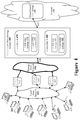
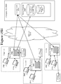
- FIG. 4 illustrates one example of a hierarchical mass storage system 460 for use within an office environment.
- the hierarchical mass storage system 460 combines together solid-state storage, hard disk storage, and even a cloud-based data storage system 491 to create a synergistic data storage system for a local storage area network 450 .
- the hierarchical mass storage system 460 may be used to provide mass data storage services to a typical networked computer environment.
- a typical networked computer environment has multiple user workstations ( 421 to 427 ) coupled to a local area network (LAN) 430.
- the LAN 430 also has multiple server systems ( 441 , 442, and 443 ) that provide various services to the users at the workstations ( 421 to 427 ) .
- Typical server system applications include an email server for sending and receiving email messages, a database server for storing specific structured data, and file server for storing general user files.
- the various server systems ( 441, 442 , and 443 ) are coupled to the hierarchical mass storage appliance 460 on a storage area network 450.
- the storage network interface 461 on the hierarchical mass storage appliance 460 uses standard storage area network protocols to provide data storage services to the local server systems ( 441, 442, and 443 ).
- the hierarchical mass storage system 460 uses storage technologies such as solid state memory ( 471 and 481 ) and hard disk storage ( 472 and 482 ) in hierarchical manner to store data locally.
- the solid state memory ( 471 and 481 ) may be implemented with a nonvolatile memory technology such as flash memory. Flash memory systems are generally faster, use less power, output less noise, and are more reliable than hard disk drive (HDD) storage systems.
- the HDD storage ( 472 and 482 ) can provide very large amounts of local storage for a low price per bit stored.
- the hierarchical mass storage system 460 may also be coupled to a cloud-based storage system 491 through a second interface using an internet connection 465 in order to take advantage of the benefits of a remote cloud-based data storage service 491.
- SAN storage area network
- the use of a storage area network (SAN) interface 461 on the hierarchical mass storage system 460 allows administrators to use the hierarchical mass storage system 460 like a conventional SAN storage device. Multiple server systems may share the hierarchical mass storage system 460 using the standard storage area network 450 .
- the use of a second interface 465 coupled to a cloud storage provider 491 allows the hierarchical mass storage system 460 to provide additional storage resources that can be used as needed.
- storage area networks allow administrators to decouple the data storage function away from server systems such that only a single unified data storage system needs to be maintained.
- all of the server systems may be coupled to storage area network 450 that is used to handle raw data storage reads and writes.
- a single hierarchical mass storage system 460 coupled to the storage area network 450 may handle data storage operations for the entire storage area network 450 . (Note that additional hierarchical mass storage systems or conventional storage devices may also be coupled to the storage area network 450 for additional storage capacity.)
- the hierarchical mass storage system 460 includes two different controller units: controller A 470 and controller B 480. These two different controller units may be used to provide a fault-tolerant mirrored storage system wherein either controller can take over if the other controller fails. Alternatively, the two controllers ( 470 and 480 ) may be used to "statically load balance" data volumes so that the controllers are each servicing half of the data storage requests when both controllers are healthy thereby increasing performance. When either controller fails in such a configuration, the remaining functioning controller takes on double workload, slowing down to some degree but providing continuous storage service for all of the data volumes.
- Controller unit A 470 and controller unit B 480 may each have local data storage systems.
- each controller has solid-state memory storage ( 471 and 481 ) and hard disk based storage ( 472 and 482 ).
- the local data storage systems handle all data write requests from the server systems ( 441 , 442 , and 443 ).
- the local data storage systems also handles data read operations for data that is currently stored in the local data storage systems.
- the hierarchical mass storage system 460 may also use data storage provided by a cloud-based data storage system 491 available on the internet 490.
- the hierarchical mass storage system 460 attempts to keep all frequently accessed data within the local data storage systems such that the vast majority of read operations are handled locally within the hierarchical mass storage system 460.
- the hierarchical mass storage system 460 will begin to store less frequently accessed data at the cloud-based data storage system 491. This allows the hierarchical mass storage system 460 to take advantage of an infinitely large storage system that is maintained by experts that run the cloud-based data storage system 491 while having local storage performance for frequently accessed data (the data stored in the local data storage systems).
- a hierarchical mass storage system 460 that uses cloud-based data storage acts as an intermediary between an on-site SAN 450 and an off-site cloud-based data storage provider 491 .
- the hierarchical mass storage system 460 must reconcile the significant differences between the front-end interface 461 to SAN 450 and the back-end 465 interface to the cloud-based data storage system 491 .
- One significant difference is the speed differential since the SAN 450 generally operates at very fast speeds (such as one gigabit per second) and the internet connection 465 may only operate at ten megabits per second.
- the hierarchical mass storage system 460 takes advantage of the manner in which data storage systems are generally used. Most mass data storage systems only need to handle a relatively small amount of dynamic data that is frequently accessed as set forth with reference to FIG. 3 . For example, an email server needs to store new email messages every day and a file server needs to handle a limited number of files that are actively being accessed by users. However, the vast majority of the data stored on a mass storage system is generally static and rarely accessed. For example, file servers may store archives of old documents that are no longer being accessed regularly.
- a core concept of the hierarchical mass storage system 460 is the efficient use of the local data storage available within the hierarchical mass storage system 460 . As long as the hierarchical mass storage system 460 accurately identifies the data that is most frequently accessed and keeps that frequently-accessed data in the local data storage ( 471 , 481, 472 and 482 ) then the vast majority of storage requests (both read operations and write operations) received on the SAN interface 461 can be serviced using only the local data storage systems ( 471 , 481 , 472 and 482 ). This will greatly reduce the amount of data traffic on the interface 465 to the cloud-based data storage 491 thus hiding the speed differential between the two interfaces from users of the hierarchical mass storage system 460.
- the hierarchical mass storage system 460 uses both intelligent data-tiering algorithms and storage space optimization techniques.
- the data-tiering algorithms are used to identify the most frequently accessed data and keep that frequently accessed data in the local storage system.
- the data-tiering algorithms may also use intelligent buffering systems like read-ahead caching to prevent cache misses. For example, by using heuristics to identify data that is likely to be requested soon, the hierarchical mass storage system 460 may issue predictive requests for data currently stored at the cloud-based data storage 491 before receiving an actual incoming request for such data.
- Various storage space optimization techniques may be used to store as much data in the local storage space. The techniques that may be used include the identification and elimination of duplicated data and data compression.
- the administrator of the hierarchical mass storage system 460 may be allowed to allocate and configure data storage in an application dependent manner. For example, if a particular application uses a certain set of data infrequently but a low latency response is needed when that data is accessed then an administrator may be allowed to specify this limitation for that application or for that specific data set. In this manner, the hierarchical mass storage system 460 will ensure that a local copy exists or will pro-actively fetch from the cloud and move it to the local storage if previously tiered to the cloud-based storage 491. Other data sets may be explicitly marked as 'archive' data such that the designated archive data is quickly sent off to the cloud-based storage provider 491.
- the hierarchical mass storage system may allow an administrator to designate a data volume as a 100% local volume.
- the hierarchical mass storage system 460 will ensure that such a designated 100% local volume will be stored in some combination of local storage.
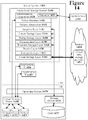
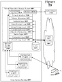
- FIG. 5 illustrates a conceptual block diagram of one particular architecture that may be used to construct a hierarchical mass storage system 500.
- an administration component 510 that is used for configuring, controlling, and monitoring a hierarchical mass storage system 500.
- An administrator may access the administration component 510 through an interface coupled to a local area network 505.
- An administrator uses the administration component 510 to initially configure the hierarchical mass storage system 500.
- an administrator specifies which virtual storage to expose to hosts on the storage area network (SAN) 501. This is similar to legacy systems where the administrator specifies which LUNs in a storage array to expose to hosts.
- the administrator also specifies the addresses and access information for the cloud storage provider(s) 591 that will be used. The administrator may specify a storage limit but this is generally not advisable since the hierarchical storage system 500 should be allowed to grow as needed.
- the administrator may also specify bandwidth constraints of the communication link 596 to the cloud data storage provider 591 and bandwidth constraints of the specific cloud data storage provider 591 (the maximum rate at which the cloud storage provider will handle data access requests).
- the bandwidth constraints of the communication link 596 can be used to ensure that the hierarchical mass storage system 500 does not attempt to send data faster than the communication link 596 can handle the data.
- the communication link 596 is shared by other users (such as an internet connection shared with human users, mail servers, and other internet users), the hierarchical mass storage system 500 can be configured to use less than the full bandwidth available on the communication link 596.
- an administrator may use the administration component 510 for several different maintenance operations.
- the administration component 510 may be used to schedule periodic snapshots of the data volumes in the hierarchical mass storage system 500 and make back-up copies of those snapshot volumes in the cloud-based storage. Additional data volumes may be added to the hierarchical storage system 500 or existing data volumes may be removed.
- the administration component 510 will collect operation statistics 511 that may be used to measure the performance of the hierarchical mass storage system 500.
- the operation statistics 511 may be analyzed and used to alter the configuration of the hierarchical mass storage system 500 to improve performance.
- Each lower layer in the data storage request stack 515 may generate its own individual statistics.
- the administration component 510 may periodically poll the lower layers and various other parts of the hierarchical mass storage system 500 to create a centralized collection of all the hierarchical mass storage system statistics.
- the main component of the hierarchical mass storage system 500 is a multilayered data storage request stack 515 that handles all data storage requests issue to the hierarchical mass storage system 500.
- Data storage requests are received at the top of the data storage request stack 515 and the various data storage layers attempt to resolve the data requests. When a layer cannot fully resolve a request then that layer passes on a request to a lower layer until the data request is ultimately resolved.
- the details of the data storage request handling stack 515 will be disclosed layer by layer in later sections of this document.
- the top layer of the data storage request stack 515 is a storage area network (SAN) interface layer 520 that is coupled through front-end interface 502 to a SAN 501.
- the SAN interface layer 520 receives storage requests from local systems such as servers 507 and 508.
- the front-end interface 502 of the hierarchical mass storage system 500 will generally use well-known SAN protocols. Examples of well-known SAN protocols include the industry standard Internet Small Computer System Interface (iSCSI) protocol and the Fiber Channel Protocol (FCP). These SAN protocols allow storage clients to perform operations such as start, stop, read, write, and format on data storage units addressed by logical unit numbers (LUNs).
- iSCSI Internet Small Computer System Interface
- FCP Fiber Channel Protocol
- the top layers ( 520, 531, and 532 ) of the data storage request handling stack 515 handle some formalities in processing storage requests. Beneath the formality layers are a set of hierarchical data storage layers.
- a first data storage layer, the linear storage layer 540 is optimized for quickly handling data requests by locally storing data in a relatively raw format.
- a second data storage layer, the deduplicated storage layer 550 locally stores data in a more efficient manner by identifying and eliminating duplicate data,
- a third data storage layer, the transient storage layer 560 is optimized for locally storing large amounts of data in a very dense compressed form.
- a fourth data storage layer uses cloud-based storage to store a limitless amount of data by storing data off site at a cloud-based data storage provider 591 .
- FIG. 5 only illustrates one possible hierarchical storage system and that other hierarchical storage systems may use additional or fewer data storage layers.
- FIG. 5 To fully describe the data storage request handling stack 515 of FIG. 5 , each the layers in the storage request handling stack will be described in further detail individually.
- the storage area network interface 520 implements the well-known iSCSI protocol that is used to accept SCSI commands carried on a TCP/IP network.
- iSCSI Peripheral Component Interconnect Express
- any other data storage protocol may be implemented at the top of the storage request handling stack 515.
- the SAN interface 520 exposes iSCSI volumes to hosts on the SAN 501.
- the SAN interface 520 receives iSCSI data storage requests from the hosts and responds to those data storage requests.
- the SAN interface 520 parses iSCSI commands and determines how the commands should be handled. Many of the administrative iSCSI requests that are not directly related to reading and writing data can be fully handled by the SAN interface layer 520.
- the SAN interface layer 520 passes data storage requests down the data storage request stack 515 to the next layer to handle such data storage requests.
- the volume abstraction layer 531 handles many of the formalities in keeping track of the different volumes stored by the hierarchical mass storage system 500 .
- the volume abstraction layer 531 keeps track of the data volumes that exist, the size of each volume, access control lists (ACLs), and other administrative information.
- ACLs access control lists
- the volume abstraction layer 531 handles some of the volume management tasks such that the lower layers of the storage request handling stack 515 can concentrate on actual data storage.
- the snapshot layer 532 is used for taking "snapshots" of specified data volumes in the hierarchical mass storage system 500 upon receiving a request for a snapshot.
- a snapshot is the state of a data volume at a particular moment in time.
- the snapshot layer 532 creates a new volume that initially only consists of a time map for the snapshot volume that specifies when the snapshot was taken and a pointer to the parent volume. If there are no new writes to the parent volume, then the current data of that parent volume can be used as the data for the snapshot volume.
- a data storage request is then passed to the linear storage layer 540 that is first level of data storage in the hierarchical mass storage system 500.
- the linear storage layer 540 is high performance data storage layer designed to handle "hot" data. Hot data is defined as data that is frequently read and/or written.
- the linear storage layer 540 will generally receive data storage requests addressed with traditional data storage semantic terms such as logical volumes, logical block addresses (LBA), and block transfer lengths (BTL).
- LBA logical block addresses
- BTL block transfer lengths
- the front-end of the hierarchical mass storage system 500 may implement many different possible data storage protocols that use different data storage addressing systems. However, as long as the hierarchical mass storage system 500 properly responds to all data storage requests received, the hierarchical mass storage system 500 is free to use any different type of addressing system internally,
- the hierarchical mass storage system 500 uses a flat linear addressing system for each data volume wherein each logical volume is divided into fixed sized "chunks" that are an even multiple of the logical blocks (SCSI logical blocks are typically 512 bytes long) used by most disk-based storage systems.
- a very simple translation system can be used to translate data requests made in terms of logical block address (LBA) ranges on a disk (or any other data storage addressing system) into the chunk-based linear addressing system used within the linear storage layer 540.
- LBA logical block address
- each fixed-size chunk is 256 kilobytes long (which can fit 512 logical blocks that are each 512 bytes long). However this is merely one particular design choice and other sizes may be used.
- the linear storage layer 540 stores data in an allocated linear storage area 547 of local data storage.
- solid state memory such as flash memory is used to store all data for the linear storage layer 540. Flash memory can quickly handle storage requests and is nonvolatile such that the data will remain stored even if there is a power loss,
- the linear storage layer 540 maintains a linear storage map 541 to keep track of where the all the data is stored. Specifically, for each data volume stored in the hierarchical mass storage system 500 , the linear storage map 541 specifies where each chunk of data resides (and thus how the data may be obtained). For data chunks that are currently stored within the linear storage layer 540, the linear storage map 541 may specify a specific physical memory address in the linear data storage area 547 . For all of the data that is not currently stored within the linear storage layer 540 , the linear storage map 541 may specify a set of data fingerprints used to uniquely identify data slices stored within lower data storage levels of the data storage request stack 515. In one particular embodiment, a thirty-two byte long SHA-256 fingerprint is used to uniquely identify data slices stored within the lower data storage layers.
- FIG. 6 conceptually illustrates how the first three various data storage layers use the local data storage, Note that FIG. 6 is conceptual only and that many details are omitted for clarity.
- the linear storage layer 640 uses a linear storage map 641 that maps each data chunk either to a location in linear storage 647 or to a set of fingerprint identifiers that represent the data chunk.
- the fingerprint identifiers are used to locate the requested data in lower data layers of the storage request handling stack.
- chunk 0 is stored in the linear storage area 647 as indicated by a pointer.
- Chunk 1 is stored in lower data storage layer(s) since the linear storage map 641 specifies a set of fingerprint identifiers.
- Each of the fingerprint identifiers uniquely specifies a data slice of the data chunk.
- the set of data slices is equal to the size of a data chunk (which is 256K in one particular embodiment).
- the linear storage map 641 may be implemented with an ordered linked list that links together entries each containing a pointer to a chunk of data in the linear storage area 647 or a set of fingerprint identifiers for data slices stored in lower data storage layers.
- the linked list entries will contain a series of entries with data fingerprints where the total size of the data slices referred to by the fingerprint identifiers equals one chunk size.
- the linked list may be supplemented by additional data structures used to improve the search of the linked list. For example, a red-black tree, a hash table, or another similar data structure containing pointers to the linked list nodes may be used to improve the speed of searching the linked list.
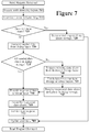
- a read request received from a host client is first processed by the SAN interface layer, the volume abstraction layer, the snapshot layer, and any other initial layer at stage 705.
- the read request is then passed to the linear storage layer 640 to obtain the data.
- the linear storage layer 640 first examines the linear storage map 641 for the requested data at stages 710 and 715 to determine how to respond to the read request. If the requested data is available in the linear storage 647 then the linear storage layer 640 simply reads the data from the linear storage area 647 and responds to the read request at stage 720 . The system may then update some statistics (such as statistics used to determine if the data is hot, warm, or cold) at stage 780 and it is then done handling the read request.
- some statistics such as statistics used to determine if the data is hot, warm, or cold
- the linear storage layer 640 requests the needed data from lower layers of the data storage request stack at stage 730 .
- the request is made by requesting the fingerprints of the needed data slices. Note that a read request may only need a few data slices of data if the read request only requested a small amount of data within a particular chunk of data.
- the next lower layer is the deduplicated storage layer 650 in FIG. 6 . This document may use the term 'dedup' when referring to aspects the deduplicated layer,
- the deduplicated storage layer 650 examines the deduplicated storage map 651 to determine if all the requested data slices are in the deduplicated storage area 657 . If the deduplicated storage layer 650 has all the needed data slices, then the deduplicated storage layer 650 can respond with the requested data at stage 750. If the deduplicated storage layer 650 does not have all the requested data slices then the deduplicated storage layer 650 will request the needed data slices from lower data storage layers at stage 740. In this particular embodiment, the request will be made to the next lower layer of the storage request handling stack, the transient storage layer 660.
- the transient storage layer 660 handles the data request.
- the transient storage layer 660 examines the transient storage map 661. If the transient storage layer 660 has the requested data then it returns that data. If the transient storage layer 660 does not have the requested data then the transient storage layer 660 may request and receive the missing data from lower data layers.
- the system proceeds in this layered manner until at stage 745 , the deduplicated storage layer 650 receives all of the requested data from the lower layers and places the requested data into the deduplicated storage area 657 .
- the deduplicated storage layer 650 can then respond to the linear storage layer 640 with the requested data at stage 750 .
- the linear storage layer 640 Upon receiving the requested data slices from deduplicated storage layer 650 , the linear storage layer 640 will assemble the requested data from the received data slices at stage 760. Finally, the linear storage layer 640 can then respond to the read request with the requested data at stage 770. The statistics counters can then be updated at stage 780 .
- servicing the read request at stage 720 will be faster than servicing the read request when the data must be fetched from the lower data storage layers. Furthermore, the lower the data layer that must be accessed, the more time that will be required to handle the read request.
- a write request received from a host client is first processed by the initial formality layers such as the SAN interface layer, the volume abstraction layer, and the snapshot layers at stage 805 .
- the write request is then passed to the linear storage layer 640 where the linear storage layer 640 first examines the linear storage map 641 at stages 810 and 815 to determine how to handle to the write request. If the write is directed at a data chunk that is already available in the linear storage area 647 then the write request is handled by proceeding to stage 850 and writing the new data into the appropriate data chunk within the linear storage area 647 at stage 850.
- the system may then also update some statistics at stage 860 . At this point, the write request has been fully handled using only the linear storage layer 640 .
- the linear storage layer 640 will generally first pull the data for the target data chunk into the linear storage layer 640 to over write the existing data.
- the reason that data is pulled up into the linear storage layer 640 before it is overwritten is so that if a failure occurs during a write operation, the failure will at least leave the old data which has been partially over-written by new data. This is the way that a traditional disk based storage system operates such that application programs are already prepared to handle corrupted data due to such a failure occurring during a write operation.
- the linear storage layer 640 may first need to allocate a new chunk of memory in the linear storage area 647 at stage 820. (Generally, the system will always keep a few memory chunks available for handling new incoming write options.) Allocating a new memory chunk may be performed by spilling data from an existing chunk in the linear storage area 647 down to a lower data storage layer. Spilling a data chunk down to a lower data storage layer will be described in a later section of this document.
- the linear storage layer 640 requests all the data slices for that data chunk from the lower data storage layers of the data storage request stack at stage 830.
- the request for the data slices is made by providing the fingerprint identifiers of the needed data slices. Note that all of the data slices for the data chunk being over-written are required since the entire data chunk will now be represented in the linear storage area 647 as a single data chunk. If the deduplicated storage layer 650 does not have all the needed data slices for the chunk in the deduplicated storage 657, then the deduplicated storage layer 650 will request the missing data slices from the next lower data storage layer of the data storage request stack (the transient layer 660 in this embodiment).
- the linear storage layer 640 After receiving the requested data slices from the lower data storage layers, the linear storage layer 640 then assembles the data slices in a buffer at stage 840. The fully assembled data chunk is then copied into the free memory chunk in linear storage area 647 such that the linear storage layer 640 is now fully responsible for that particular data chunk. Thus, the linear storage layer 640 updates the linear storage map 641 to reflect that the linear storage layer 640 now has that particular chunk of memory represented within the linear storage area 647.
- the fetched data slices will generally be allowed to also remain down in the deduplicated storage area 657 .
- a primary reason that these data slices will continue to be in the deduplicated storage area 657 is that other areas of the data volume (or other data volumes) may refer to the same fetched data slices. If a data slice is not referenced by any data chunk then a garbage collection mechanism may eventually discard that unreferenced data slice.
- Unreferenced data slices may be allowed to remain in the deduplicated storage area 657 for some time. There is actually a benefit in keeping unused data slices in the deduplicated storage area 657 for a period of time. Specifically, a data chunk that was pulled up from the deduplicated storage layer 650 (or lower layers) up into the linear storage layer 640 may soon be spilled back down to the deduplicated storage layer 650. When this occurs, the pre-existing data slice in the deduplicated storage area 657 may be used again if the data slice still represents a portion of the data chunk.
- the linear storage layer 640 may then over-write the data chunk at stage 850.
- the data chunk will contain a mix of new data overwritten onto old data. As set forth above, this is a situation that existing application programs are already prepared to handle.
- the system may update some statistics. For example, a counter associated with the data chunk may be incremented to indicate that the data chunk has recently been accessed. This counter value may be used by a data-tiering algorithm to determine if the data chunk should be kept in the linear storage layer.
- the hierarchical mass storage system will only spill data down to lower data storage layers of the storage request stack when a particular storage layer needs evict old data to make room for new data.
- the linear storage layer 640 may evict a data chunk to make room for new data in the linear storage area 647.
- the eviction policy may use eviction policies similar to common cache replacement strategies.
- the system may use the well-known least-recently used (LRU), least-recently allocated (LRA), or least-frequently used (LFU) cache replacement policies to determine when a data chunk may be evicted from the linear storage layer 640.
- LRU least-recently used
- LRA least-recently allocated
- LFU least-frequently used
- the linear storage layer 540 determines that a particular data chunk is not being frequently accessed then the linear storage layer 540 spills that data chunk down to lower data storage layers for more efficient storage of the data chunk.
- the linear storage layer 540 sends the data chunk to the deduplicated storage layer 550 for storage in the deduplicated storage area 557.
- the deduplicated storage layer 550 acts as a repository for "warm" data that is not as frequently accessed as the "hot" data in the linear storage layer 540 but still accessed regularly and typically read more often than written. As the name implies, the deduplicated storage layer 550 attempts to remove duplicated data from the stored data such that the deduplicated storage layer 550 stores data more efficiently than the linear storage layer 540 .
- the data is stored as data slices.
- Each data slice is uniquely identified with a data fingerprint (such as a SHA-256 fingerprint).
- the deduplicated storage layer 550 may use a deduplicated storage map 651 to keep track of where each data slice is stored within the deduplicated storage area 557 of the local data storage system.
- FIG. 6 illustrates a conceptual diagram of the deduplicated storage map 651 and the deduplicated storage area 657 .
- the deduplicated storage map 651 may be implemented as a table that lists, for each data slice, the data fingerprint and the storage location of each data slice within the deduplicated storage area 657 .
- the deduplicated storage map 651 may be implemented as a hash table (or similar data structure) to optimize search performance. If a requested data slice is not stored within the deduplicated storage area 657 then that data slice may be presumed to be stored in lower data storage layers.
- the linear storage layer 640 When the linear storage area 647 is filled, the linear storage layer 640 must select one or more linear data chunks to spill down.
- the linear storage layer 640 uses a "least recently allocated" (LRA) policy to determine when a particular data chunk should be spilled down to a lower data storage layer.
- LRA least recently allocated
- the spilling down of data chunks may be performed by a background spill process that attempts to keep the linear storage area 647 approximately 85% full in one particular embodiment. This allows a large amount of data to be stored but keeps the linear storage layer 640 prepared to accept a new burst of data writes.
- FIG. 9 illustrates a flow diagram describing how a data slice may be spilled down from the linear storage layer 640 to the deduplicated storage layer 650.
- the linear storage layer 640 divides the data chunk into a set of individual data slices at stage 920.
- Many different techniques may be used to slice a data chunk (as used in the linear storage layer) into a set of data slices (as used in the lower data storage layers). The goal is to slice each data chunk up into individual data slices in a manner that will result in a high probability of identifying duplicate data slices.
- each data chunk is sliced up using Rabin fingerprints.
- a Rabin fingerprint is a progressive polynomial that is calculated over a defined window. It is progressive since successive Rabin fingerprints may be calculated by dropping of a byte from one end of the defined window and adding another byte to the other end of the defined window. This allows a Rabin fingerprint to sweep through a chunk of data dividing it into data chunks.
- FIG 10 conceptually illustrates how a Rabin fingerprint calculator window 1050 may sweep through data chunk 1010 progressively calculating Rabin fingerprints.
- the Rabin fingerprint system may be used to sweep through the data chunk 1010 and periodically drop anchors to define data slices.
- An anchor may be dropped when the Rabin fingerprint equals some arbitrary value.
- the system creates data slices that start at a first anchor defined by the beginning of the data chunk or the previous anchor, are at least 8K bytes long, and end when the specified arbitrary Rabin fingerprint value is generated or a 64K limit is reached (whichever occurs first). This implementation will create data slices that are all between 8K and 64K in length. If the arbitrary value is selected as a value with 16 zeroes in the least significant bits of the binary Rabin figure print, the data slices will average to be around 16K in size.
- the system then may need to allocate space in the deduplicated storage area 657 if no space is available. This may be done by selecting a least recently allocated chunk of space in the deduplicated storage area 657 and spilling the data slices in that area down into a lower data layer.
- the deduplicated storage layer 650 may also have a background process running that always attempts to keep the deduplicated storage area 657 approximately 85% filled such that the deduplicated storage layer 650 stores a large amount of data but can still always accept new data.
- the linear storage layer 640 After dividing the data chunk into data slices and ensuring that space exists in the deduplicated storage layer 650, the linear storage layer 640 then begins to spill down individual data slices from the data chunk. At stage 940 , the linear storage layer 640 first calculates a data fingerprint for a data slice. This fingerprint is a statistically unique identifier fingerprint such as a SHA-256 fingerprint. The linear storage layer 640 then provides the data slice and the fingerprint for the data slice to the deduplicated storage layer 650 at stage 950. (The data may be provided by simply passing a pointer to the data slice.)
- the deduplicated storage layer 650 examines the fingerprint identifier that it receives and searches the deduplicated storage map 651 to see if there is already an existing identical data slice already stored in the deduplicated storage area 657 .
- the deduplication may be performed in two stages. A first stage can use probabilistic methods to locate potential duplication candidates. After identifying candidates for deduplication, exhaustive algorithms verify the duplicated data and possibly adjust the data slice boundaries to obtain more duplicated data slices.
- the deduplicated storage layer 650 may discard the data at stage 980. In embodiments wherein the system maintains a reference counter to keep track of how many different data chunks refer to a particular data slice, the system may increment that reference counter. When a received data slice is not yet represented in the deduplicated storage layer 650 (the same fingerprint was not found in the deduplicated storage map 651 at stage 975 ), then the deduplicated storage layer 650 adds that data slice to the deduplicated storage map 651 at stage 990 .
- the deduplicated storage layer 650 stores the actual data slice in the deduplicated storage area 657 and creates a new entry in the deduplicated storage map 651 (which may be a hash table) that includes the data fingerprint identifier and a pointer that points to the newly added data slice.
- the deduplicated storage map 651 (which may be a hash table) that includes the data fingerprint identifier and a pointer that points to the newly added data slice.
- the linear storage layer 640 determines if this was the last data slice of the data chunk to spill down. If it is not, the linear storage layer 640 returns back to stage 940 to spill down another data slice. If this was the final data slice from the data chunk, then the linear storage layer 640 may now update the linear storage map 641 by removing the pointer to the data chunk in the linear storage area 647 and adding data fingerprint identifier entries for all of the data slices that make up the data chunk into the linear storage map 641. Thus, when a subsequent memory request is received that refers to that particular memory chunk, the system will need to access the data slices now stored in the deduplicated storage area 657 (or in lower data storage layers) by using the fingerprint identifiers.
- the deduplicated storage layer 650 greatly increases the storage efficiency. This allows many more logical volumes of data to be stored in the local storage layers beneath the linear storage layer 540 that only stores data in a raw unprocessed form. However, this increased data storage efficiency comes at a cost.
- the linear storage layer 540 must slice up each data chunk and calculate fingerprint identifiers for each data slice.
- the deduplicated storage layer 550 must handle the identification and elimination of duplicated data slices.
- spilling data into the deduplicated storage layer 550 involves significant metadata updates to maintain the deduplicated data storage map 651. However, since processing power is now very inexpensive and the bandwidth of the local storage layer is far greater than the bandwidth to the cloud data storage, this is a worthy trade-off.
- Another cost for the improved memory efficiency is that when a read request is received for a data chunk in the deduplicated storage layer 650 then that read request must be satisfied with disassembled data from the deduplicated storage area 657.
- the linear storage layer 640 must fetch each needed data slice from the deduplicated storage layer 650 (or lower data storage layers) and then reassemble the data slices to obtain the requested data chunk.
- This means that the latency time for read requests that are serviced by the deduplicated storage layer 650 will be higher than the latency time for read requests that are serviced by the linear storage layer 640.
- this latency difference is relatively small and worth the trade-off since data deduplication allows much more data to be stored within the high-speed deduplicated storage area 657 . Storing more data in the high-speed deduplicated storage area 657 will mean fewer accesses to the lower (slower) data storage layers that store data on hard disk or with the off-site cloud data storage provider which will have a much greater latency time.
- the deduplicated storage layer 550 acts as a relatively fast local tier of data storage.
- the "warm" data in the deduplicated storage layer 550 is not accessed as frequently as the data in the linear storage layer 540 but data in the deduplicated storage layer 550 is still accessed on a fairly regular basis.
- the deduplicated storage layer 550 stores data more efficiently, the deduplicated storage layer 550 will eventually run out of storage space.
- the deduplicated storage layer 550 must begin to evict existing data slices to make room for new data slices.
- the deduplicated storage layer 550 will spill the evicted data slices further down the storage request handling stack 515.
- data eviction policies used by the deduplicated storage layer 550 may be the same, similar, or different than the data eviction policies used by the linear storage layer 540 .
- some implementations of the deduplicated storage layer 650 may maintain a 'reference counter' value in the deduplicated data storage map 651 that maintains a count of the number of times each data slice is referenced by a data chunk.
- the reference counter may be used by the data eviction algorithm such that data slices that are referenced many times are less likely to be evicted from the deduplicated storage layer 650.
- the deduplicated storage layer 550 may proactively spill data slices down to the lower data storage layers before it is necessary to do so.
- the data slices may also remain locally within the hierarchical mass storage system 500 such that read requests for those data slices may be serviced quickly.
- the transient storage layer 560 may be used to store "lukewarm" data that is accessed relatively infrequently.
- the transient storage layer 560 may store data onto hard disk drives that can offer very large amounts of data storage for a low cost. However, storing data on a hard disk drive instead of within solid state memory (SSM) means that there will be a slightly longer latency time when responding to read requests.
- SSM solid state memory
- the transient storage layer 660 may maintain its own transient storage map 661 that identifies the locations of data slices stored within the transient storage area 667 .
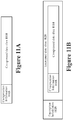
- the compression layer 559 may allow multiple different compression systems to be used. To enable this, the compression layer 559 may prepend compression information 1115 onto the compressed data slice 1110 as illustrated in Figure 11A .
- the compression information 1115 may include a code to that specifies the particular compression algorithm and version used to compress the compressed data slice 1110 . This allows the compression layer 559 to select the proper decompression system when multiple different compression systems are being used. Such an extensible system may be able to select the optimum compression system for a particular data slice. Furthermore, this allows new compression algorithms to be added to the system over time.
- the compression of the data slices accomplishes two goals. First, the compression reduces the amount of data that needs to be stored in the transient storage 567 such that the amount of data that can be stored locally within the hierarchical mass storage system 500 is increased. And second, the compression reduces the bandwidth usage on the internet connection 596 if the data slices are eventually sent to the data storage provider 591 . Reducing the bandwidth usage is very important since this reduces the large disparity between the high-speed bandwidth at the front-end storage area network connection 502 and this back-end internet connection 596 to the cloud data storage provider 591 .
- a cloud storage layer 580 that may be used to store data at an off-site cloud storage provider 591 .
- Data stored off-site will generally introduce some latency when that data is read back.
- the cloud storage layer 580 may be used in various different manners depending on how the hierarchical mass storage system 500 is configured. For example, a hierarchical mass storage system 500 may be instructed to use the cloud storage layer 580 for back-up operations only, for normal data storage only when absolutely necessary, or as just another layer of the hierarchical data mass storage system 500 .
- the hierarchical mass storage system 500 is designed to only use the local storage layers (linear, deduplicated, and transient) as primary data storage.
- the cloud storage layer 580 is only activated when an administrator specifically requests that an off-site back-up volume be created. If the hierarchical mass storage system 500 device runs low on storage space in the local storage layers then an administrator of the system will be warned such that the administrator can add more local storage capacity, delete data to create more local space, or change the configuration to begin using the cloud storage layer 580 for normal data storage.
- the hierarchical mass storage system 500 will always attempt to keep all of the data locally. However, if there is insufficient storage space left in the local storage layers (linear, deduplicated, and transient) then the hierarchical mass storage system 500 will begin to store data at the off-site cloud storage provider 591 . The administrator will be notified that off-site data is occurring such that the administrator can take various actions in response. As set forth above, the administrator may add more local storage capacity, delete data to create more local storage space, or begin using the cloud storage layer 580 for normal data storage.
- the hierarchical mass storage system 500 uses the cloud storage layer 580 as just another successive data storage tier.
- the hierarchical mass storage system 500 would never run out of storage space due to the use of extensible cloud storage.
- the cloud storage layer 580 stores "cold" data, data that is rarely accessed, at the cloud storage data provider 591 .
- a barrier layer 570 When a higher data storage layer spills a data slice down toward the cloud storage layer 580 , a barrier layer 570 first stores a copy of the data slice in a barrier storage area 547 .
- the barrier storage area 547 is used to temporarily store a copy of data that the cloud storage layer 580 will transmit to the data storage provider 591 .
- FIG . 5 illustrates the barrier storage area 547 in SSM but the barrier storage may be in SSM or on a hard disk drive.
- the barrier layer 570 stores data slices in the barrier storage 577 for a 'settlement period' that allows the data storage provider 591 to fully complete its own data storage tasks.
- the barrier layer 570 first checks the barrier storage area 547 to see if the requested data is available there. If the requested data is located in the barrier storage area 547 then the barrier layer 570 will respond to the data request using that data slice located in the barrier storage area 547 . If the requested data slice is not located in the barrier storage area 547 then the barrier layer 570 will pass the read request down to the cloud storage layer 580 so the cloud storage layer 580 can request the data slice from the cloud data storage provider 591 .
- the barrier layer 570 serves additional purposes.
- One important purpose is to handle storage request serialization. Many cloud data storage providers will perform data storage requests received in close time proximity out of the original order that the data storage requests were received in. Thus, if a purge request is transmitted and then followed a write request to the same data location, the cloud data storage provider 591 might reverse the order of these requests such that the system writes the data and then purges the data thereby destroying data! To prevent this potential disastrous occurrence, the barrier layer 570 will place a long waiting period between data storage requests that refer to the same data slice.
- the cloud storage layer 580 Before the cloud storage layer 580 transmits data to the data storage provider 591 , the cloud storage layer 580 first prepares the data slices to be sent. Specifically, the data slices may first be encrypted by encryption layer 583 . By encrypting the data, the user of the hierarchical mass storage system 500 does not need to fear for their data security. The encryption prevents any person tapping the internet connection 596 or examining the data stored at the storage provider 591 from being able to understand the real meaning of the data.
- the AES-256 encryption system was implemented within the encryption layer 583 .
- the encryption layer 583 may allow multiple different encryption systems to be used by prepending encryption information 1125 to the encrypted data slice 1120 as illustrated in Figure 11B .
- the encryption information 1125 allows the encryption layer 583 to select the proper decryption system and version when multiple different data encryption systems may be used.
- the prepended encryption information 1125 may also specify the size of the enclosed data slice since some encryption systems only operate on fixed size data and thus require padding bytes. Note that the use of pre-pending compression 1115 and encryption information 1125 allows new compression and encryption systems to be added to the hierarchical mass storage system 500 at any time.
- prepended encryption information 1125 may also be used to help with encryption key management. Encryption keys may be changed on a regular basis to improve the data security. A code may be placed into the prepended encryption information 1125 to help select the proper key for data decryption.
- the system allows an administrator to use a passphrase to generate an encryption key. Multiple levels of authority may be used to protect keys from be lost.
- a built-in system may allow a customer to contact the manufacturer of the hierarchical mass storage system 500 system if the passphrase for an encryption key has been lost.
- the compressed and encrypted data slice is provided to the cloud storage layer 580 that is responsible for transmitting data slice to the data storage provider 591 .
- the cloud storage layer 580 first creates a new data object within the cloud data storage provider 591 to store the data slice.
- the cloud storage layer 580 uses the same the fingerprint identifier from the previous storage layers as the name for the data object.
- the cloud storage layer 580 then writes (transmits) the data to the newly created data object.
- the cloud storage layer 580 then allows for the settlement period wherein it waits a specified amount of time before the data can be read back from the data storage provider 591 .
- This settlement period is a time value that may be configured based upon the particular data storage provider 591 that is being used. Once the settlement period expires, the cloud storage layer 580 informs the barrier layer 570 that the barrier layer 570 may delete the copy of the data slice that was placed in the barrier storage 577 . Thus, subsequent read operations for that data slice must be serviced by requesting the data slice back from the cloud data storage provider 591 .
- the cloud storage layer 580 may calculate a checksum value of data using the same type of checksum used by the data storage provider 591 . After receiving data for storage, the data storage provider 591 may transmit a checksum value back in an acknowledgement message. If the two checksum values do not match, the cloud storage layer 580 may retransmit the data slice. When such checksums are used, the copy of the data in the barrier storage 577 should not be removed until matching checksums have been achieved and the settlement period has expired.
- the cloud storage layer 580 does not need to maintain a map of the data slices.
- the data storage provider 591 is responsible for maintaining a system that links data slice fingerprint identifiers to the data slice objects such that the cloud storage layer 580 can request and obtain data slices back from the data storage provider 591 .
- Data read requests passed down by the transient storage layer 560 are handled in basically the same manner as write requests but in reverse order.
- the barrier layer 570 will first attempt to serve a data request using data stored in the barrier storage 577 . If the data request cannot be served from data in the barrier storage 577 , the cloud storage layer 580 will send a read request to the cloud data storage provider 591 using the data slice fingerprint identifier as the name of the requested data object. After receiving a response from the cloud data storage provider 591 , the cloud storage layer 580 can perform data integrity check on the received data slice by calculating a checksum the received data. If the calculated checksum does not match the checksum received from the deduplicated storage layer 550 then the cloud data storage provider 591 may have corrupted the data. Retries may be attempted to obtain the proper data from the cloud data storage provider 591 . If the proper data cannot be retrieved, a 'media error' message may be propagated back up the data storage stack 515 .
- the deduplicated storage layer 550 will receive the data slice that was fetched from the cloud and may place that data back into its duplicated storage area 557 .
- the deduplicated storage layer 550 passes the requested data up to the linear storage layer 540 and finally the linear storage layer completes the read request by assembling the requested data as set forth in stage 760 of FIG. 7 .
- the data slice may be stored within several different storage layers of the data request handling stack 515 and will continue to remain at the cloud data storage provider 591 . If the deduplicated storage layer 550 again evicts a data slice that was also stored in the transient storage layer 560 (and that data slice has not changed) then that data slice does not need to be stored in the transient storage layer 560 again since it already exists there. Thus, the deduplicated storage layer 550 may just delete its copy of the data slice.
- the data request handling stack 515 and its various data storage layers may be implemented in various different manners depending on the needs of a specific application. Note that the various different techniques may be used independently or in a combined hierarchical mass storage system 500 .
- the hierarchical mass storage system 500 of FIG . 5 may be implemented as mass storage appliance 460 for an office environment as illustrated FIG . 4 wherein the mass storage appliance 460 provides data storage services to several server systems ( 441, 442, and 443 ).
- the server systems ( 441, 442, and 443 ) provide various services to a collection of user workstations ( 421 to 427 ).
- the office environment depicted within FIG . 4 will generally require a local information technology department to configure and maintain the local area network 430 , the various server systems ( 441 , 442 , and 443 ), the storage area network 450 , the hierarchical mass storage system 460 , and the account with the cloud storage provider 491 .
- FIG . 12 illustrates the computer infrastructure for a small office environment with just three local employees that use workstations 1221 , 1222 , and 1223 .
- the small office of FIG . 12 consists of a local area network 123 0, a small local server 1250 , and an internet gateway device 1271 that provide internet service.
- the small local server 1250 runs a few server applications such as server application A 1256 and server application B 1257 that provide some local services to the office such as file sharing, print sharing, email, etc.
- DAS direct attached storage
- DAS direct attached storage
- FIG . 13 illustrates a small office computer environment very similar to FIG 12 wherein the small server system 1350 includes an integrated hierarchical storage system 1355 .
- the integrated hierarchical storage system 1355 provides data storage services to the applications that run on the server system 1350 (Application A 1356 and Application B 1357 ).
- the small office environment of FIG . 13 with a server system 1350 that includes an integrated hierarchical storage system 1355 provides several advantages over the traditional small office environment of FIG . 12 .
- the integrated hierarchical storage system 1355 uses a cloud-based data storage service 1391 to provide ever-expanding storage capacity to the server system 1350 .
- the integrated hierarchical storage system 1355 uses data deduplication and compression techniques to use the local storage capacity within the direct attached storage 1351 very efficiently. But one of the most important aspects of the integrated hierarchical storage system 1355 is the remote administration capabilities.
- a hierarchical storage system 500 includes an administration component 510 .
- the administration component 510 allows the hierarchical storage system 500 to be configured and maintained remotely through a network interface.
- an administrator 1311 at the IT department of a company headquarters 1310 (or at contract agency) can remotely access, configure, and maintain all of the data storage functions of the server system 1350 .
- Data storage related maintenance tasks generally require a person to be physically present since the administrator must often deal with the physical storage hardware. For example, an administrator may need to physically replace existing hard disk drives with larger hard disk drives when an office has outgrown the current data storage capacity.
- the hierarchical storage system 1355 virtualizes disk volumes and uses ever-expandable cloud-based storage, the hierarchical storage system 1355 allows most data storage maintenance tasks to be handled remotely.
- a local administrator must usually be present to handle the physical back-up media when backing-up the directed attached storage 1251 with back-up system 1259 .
- a remote administrator 1311 may instruct the hierarchical storage system 1355 to create back-ups of data volumes in the cloud-based data storage 1391 .
- the remote administrator 1311 may instruct the hierarchical storage system 1355 to create a new data volume.
- the creation of a new data volume will not require the physical addition of a new disk since the hierarchical storage system 1355 will instead evict old inactive data from the local directed attached storage 1251 as needed to create room for the new data volume. Thus, as long as the local storage systems are able to handle the data that is actively used on server system 1350 , no new local storage will be required. Instead, the cloud-based data storage 1391 acts as an ever-expanding storage system.
- FIG . 14 illustrates a detailed block diagram of one embodiment of server system 1400 with an integrated hierarchical storage system 1404 .
- the hierarchical storage system 1404 may be implemented within Microsoft Windows, Linux, and other operating systems.
- the software environment is divided into user space and operating system (or kernel) space.
- the operating system, various libraries, and device drivers execute in the operating system space.
- Programs running in the operating system space are granted more privileges and are able to access hardware features directly.
- application programs execute in a user space that is granted fewer privileges and is not allowed to access hardware features directly.
- application A 1456 and application B 1457 execute in the user space. This arrangement allows computer systems to operate in a more robust manner since application programs, whether intentionally malicious or merely poorly written, are prevented from performing operations that would cause the server system to crash.
- application programs To access storage resources (which requires access to some data storage hardware), application programs must issue requests to the operating system 1479 .
- application A 1456 and application B 1457 may issue storage requests through operating system 1479 that are provided to a virtual storage driver 1480 that handles data storage requests.
- a normal storage driver would fulfill the storage requests by storing data onto a data storage device such as direct attached storage 1475 .
- the virtual storage driver 1480 instead appears to make virtual disk volumes 1451 , 1452 , and 1453 available but handles the storage requests for these virtual disk volumes by passing the requests to the hierarchical storage system 1404 .
- the virtual storage driver 1480 may be implemented as a Storport driver.
- the virtual storage driver 1480 may be implemented as a virtual SCSI device driver.
- an application program may make a storage request through the file system 211 of an operating system or may make a direct storage request to a storage control system to store a raw block of data.
- a virtual storage driver 1480 within the operating system space, the disclosed system can handle advanced storage requests from applications such as databases that use raw block storage requests instead of simple file requests through the file system.
- the data storage handling stack of the hierarchical storage system 1404 is implemented within user space. This may be done since there are more programming support tools for developing in user space and user space applications do not require approval from the entity that creates the operating system. However, in other embodiments, the data storage handling stack may be implemented in the operating system space.
- the virtual storage driver 1480 passes all storage requests to a driver interface 1420 at the top of the data storage handling stack. The data storage request is then processed by the various different layers of the data storage handling stack until the request is fully resolved.
- the various data storage layers (linear storage 1440 , deduplicated storage 1450 , transient storage 1460 , etc.) access a real storage driver 1474 that handles storage requests for a real direct attached storage device 1475 in the server system.
- the linear storage layer 1440 may use solid-state storage to reduce latency and have high throughput.
- low latency performance may not be of paramount performance such that all of the local data storage levels may simply use a local hard disk drive system.
- the integrated hierarchical storage system 1404 will still benefit from the increased storage efficiency provided by performing data duplication in the deduplication storage layer 1450 and data compression in the transient storage layer 1460 .
- server-based hierarchical storage system 1404 will benefit from a wealth of storage management features such as remote volume creation, cloud-based back-ups, ever-expanding storage size without hardware upgrades, remote volume duplication, centralized storage management across multiple sites, etc. The importance of these features will be described in greater detail in the next section.
- the cloud storage layer 1481 of the data storage handling stack interacts with a cloud data storage provider 1491 to enable the server system 1400 to handle far more data than can be stored just in the direct attached storage device 1475 .
- the cloud storage layer's ability to store data at the cloud data storage provider 1491 allows the hierarchical storage system 1404 to provide ever-expanding data store on the server system 1400 .
- FIGS. 15A to 15H Having a server system with an integrated hierarchical storage system greatly simplifies the creation and support of satellite small offices. To illustrate the ease in which satellite offices can be supported, a set of examples will be presented with reference to FIGS. 15A to 15H .
- FIG. 15A illustrate a block diagram of a company with a headquarters 1510 and two satellite offices in London and Zurich.
- An administrator 1511 at headquarters 1510 maintains two server systems 1560 and 1550 at the satellite offices in London and Zurich, respectively that have an integrated hierarchical data storage system.
- Each of the satellite office server system ( 1560 and 1550 ) uses a regional cloud storage provider to provide high-speed cloud storage service ( 1569 and 1559 , respectively). Note that many countries have data privacy rules that describe how data must be handled such that storing data with regional cloud storage provider will help fulfill such legal obligations.
- the company decides to open a new satellite office in Tokyo.
- a new server system 1570 with an integrated hierarchical storage system is built and sent to the Tokyo office. Once the server system 1570 arrives at the new Tokyo office it is coupled to an internet connection and booted up.
- the administrator 1511 can log into the server system 1570 and configure the server system 1570 for operation as illustrated in FIG . 15B .
- One of the first tasks the administrator 1511 does is to open an account with a local cloud storage provider 1579 and configure the server system 1570 to use local cloud storage provider 1579 as bottom tier of the hierarchical data storage system.
- the Tokyo server system 1570 is ready to handle an ever-expanding amount of data storage.
- the administrator 1511 may wish to create some virtual data volumes and populate the Tokyo server system 1570 with applications and data for use by the Tokyo office. To do this, the administrator 1511 may configure the cloud storage layer in the Tokyo server system 1570 to use a server system 1507 at the headquarters 1510 as a source of data as illustrated in FIG . 15C . Then, the administrator 1511 may 'restore' a satellite office template volume 1551 at the headquarters 1510 within the Tokyo server system 1570 .
- FIG . 15D illustrates the state of the Tokyo server system 1570 after restoring the satellite office template volume onto the Tokyo server system 1570 and creating other needed data volumes.
- the satellite office template volume 1551 at the headquarters 1510 is only be used as back-up source volume. And that any changes made to the restored volume will only affect the local drive in the Tokyo server system 1570 and the cloud storage service 1579 used by the Tokyo server system 1570 .
- the administrator 1511 may install and configure any server applications that are needed on the Tokyo server system 1570 .
- the Tokyo server system 1570 has been configure and loaded with applications ready for use.
- users at workstations 1571 and 1572 may begin using the Tokyo server system 1570 as illustrated in FIG . 15E .
- the server system 1570 with a hierarchical storage system can greatly facilitate this task of moving the office computer infrastructure.
- the first task is to have the administrator 1511 create a back-up of the needed data volumes from the Tokyo server system 1570 . This may be performed by taking a snapshot of the needed volumes and then creating cloud-based back-ups of the snapshot volumes either at cloud store 1579 or at the company headquarters 1510 .
- FIG 15F illustrates a back-up 1552 of the server system 1570 from the closed Tokyo office at the server system 1507 in the company headquarters 1510 .
- a new Singapore office may then be quickly open by following the same steps set forth with reference to FIG . 15A to 15E except that instead of restoring the satellite office template volume 1551 , the administrator instead restores the Tokyo office back-up volume 1552 at the new Singapore office.
- the final outcome is illustrated in FIG. 15H .
- the Tokyo server system 1570 can be backed-up immediately after the Tokyo office closes for the last day and immediately restored at the Singapore office. In this manner, the new Singapore office can open up the day after the Tokyo office closed with all of the data from the just-closed Tokyo office immediately available at the new Singapore office!
- the hierarchical storage systems can be used to easily distribute volumes of information to all of the different satellite office.
- the company headquarters 1510 has created a library volume 1553 as a back-up volume on server system 1507.
- the library volume 1553 contains information that the company headquarters would like distributed to all of the different satellite offices such as the company policy, information on the healthcare insurance, training videos, software licensed for use by all employees, etc.
- the administrator contacts each of the server systems 1550, 1560, and 1580 and instructs those servers to restore the library volume 1553 as a local volume.
- Each satellite server 1550 , 1560, and 1580 will then create a local volume that contains all the information from the library volume 1553.
- all of the data from the library volume 1553 may not be immediately transmitted to all of the satellite servers ( 1550, 1560 , and 1580 ). Instead, just an index of information needed to create the appearance of a local library volume 1553 is transmitted initially. Then, as users at the various satellite offices request documents from the local instance of the library volume, various pieces of the library volume 1553 will be transmitted as requested. This technique reduces unnecessary network bandwidth usage and does not waste local storage space for documents that no user will access.
- FIG. 13 There are times when even managing a single small physical server 1350 as illustrated in FIG. 13 may not be ideal. For example, if there are a number of individual sales people working in distant geographical regions then there is no convenient central office to host a server for those remote sales people. Alternatively, a company may decide to outsource the physical maintenance of all server hardware by just moving all server based applications to a cloud-based computer service provider. To accomplish this goal, the server system 1400 with an integrated hierarchical storage system 1404 may be moved into a cloud-based virtual server. Ideally, the cloud-based computer service provider will be located at a geographical location relatively close to the users such that response times are optimized.
- FIG. 16 illustrates a virtual server system 1600 with an integrated hierarchical storage system 1604 that is executing at a cloud service provider 1699 .
- an entity can eliminate and outsource all the tasks of physically maintaining server hardware.
- Individual users such as a user at thin-client system 1698, may access server applications from the virtual server system 1600 across the internet 1690.
- many geographically remote individual users such as geographically dispersed sales personnel can all share server applications 1656 and 1656 .
- the advantages of the different layers of the hierarchical storage system 1404 may not be appreciated as much.
- the linear storage layer 1640 may not have a very low latency response since the cloud-based environment may not support allocating certain regions of storage as solid state memory but will instead use disk storage as illustrated in FIG. 16 .
- the storage size allocations and eviction policies used for the various storage layers may be adjusted to adapt to the cloud environment.
- the virtual server system 1600 implementation of FIG. 16 uses the specialized virtual storage driver 1680 to provide storage services to application programs. Due to this architecture, any server applications that wish to use the hierarchical storage system 1604 must run on the same virtual server system 1600. For example, server applications A 1656 and B 1657 execute on the virtual server system 1600 and thus can access the virtual storage driver 1680 in that virtual server system 1600. To improve performance, each application program may be assigned its own individual virtual machine.
- FIG. 17 illustrates a cloud service provider 1799 that is running two separate virtual server systems ( 1700 and 1701 ) wherein each server system is running a single server application ( 1756 and 1757, respectively). Additional virtual servers may be spawned to handle additional applications wherein each virtual server has its own hierarchical storage system instance.
- This arrangement allows the system to take advantage of the cloud computing aspect of being about to scale out instead of scale up.
- multiple different computer instances may be assigned handle individual tasks instead of using a single large computer instance that runs multiple disparate applications.
- a system may use a cluster of smaller nodes that can grow or shrink in members, rather than one large compute node that consumes a predefined set of resources.
- the hierarchical storage system may be generalized to allow other applications running on other machines (real or virtual) to more easily access the cloud-based hierarchical storage system.
- FIG. 18 illustrates a virtual hierarchical storage system 1804 that is executing at a cloud service provider 1899 .
- the virtual hierarchical storage system 1804 exposes a network storage interface 1880 such as an iSCSI interface to the outside world.
- server applications A 1871, B 1872, and C 1873 can run in their own virtual systems (or on physical system at an office) and access the storage services through the network storage interface 1880 .
- An individual user at thin-client system 1898 is illustrated accessing the server application C 1873 across the internet 1890 .
- FIG. 18 makes it easier to scale up applications services faster. Specifically, as many instances of applications are necessary may be created in their own virtual servers and allowed to access the same network storage interface 1880 such that when processing power is needed to handle numerous simultaneous users, application processing power can be scaled up quickly.
- the ability to host a virtual hierarchical storage system 1804 within cloud-based service provider 1899 offers the ability to create a low-cost disaster recovery system for any entity that uses a hierarchical storage system.
- an administrator can easily create daily back-up volumes stored at the cloud storage provider used by the hierarchical storage system.
- a disaster strikes (such as an office building housing the hierarchical storage appliance 460 or integrated hierarchical storage server 1350 burns down)
- the most recent back-up volume can be restored into cloud-based virtual hierarchical storage system 1804 at cloud service provider 1899 .
- cloud-based application programs such as applications 1871, 1872 , and 1873 may begin operating using the restored data volumes.
- any organization that uses a hierarchical storage system has the ability to quickly restore an entire back-office infrastructure within a cloud service provider 1899.
- the stand-by disaster recovery effectively costs nothing to maintain since an account with a cloud service provider 1899 can immediately be open when a disaster strikes.
Landscapes
- Engineering & Computer Science (AREA)
- Theoretical Computer Science (AREA)
- Physics & Mathematics (AREA)
- General Engineering & Computer Science (AREA)
- General Physics & Mathematics (AREA)
- Software Systems (AREA)
- Human Computer Interaction (AREA)
- Data Mining & Analysis (AREA)
- Databases & Information Systems (AREA)
- Computer Security & Cryptography (AREA)
- Information Retrieval, Db Structures And Fs Structures Therefor (AREA)
- Radio Relay Systems (AREA)
- Mobile Radio Communication Systems (AREA)
Description
- The present patent application claims the benefit of the previously filed provisional patent application entitled "System And Methods For Implementing A Server-Based Hierarchical Mass Storage System" filed on May 20, 2012 having serial number
61/649,305 - The present invention relates to the field of digital mass storage systems. In particular, but not by way of limitation, the present disclosure teaches several techniques for implementing hierarchical mass storage system within a server system or in cloud-based virtual machine.
- Computer systems have become an indispensable tool used in modern life. Nearly every business and government entity is now dependent upon computer systems for digital communication, project planning, document creation, information storage, transaction processing, project management, inventory management, financial operations, and a large number of other mission critical services.
- Due to the critical importance of information technology to most organizations, it is critical to be able to repair or replace any part of the information technology infrastructure that fails. Although individual pieces of computer hardware and computer software can easily be replaced by an entity by purchasing new computer equipment or computer software, the entity's accumulated store of digital information cannot easily be replaced. Thus, digital information storage and digital information protection is one of the most critical parts of any modern information technology infrastructure system.
- Modern organizations need to be able to support a wide variety of different computer environments for their computer users. An information technology department may be required to provide digital information storage services to a large central headquarters campus, other geographically remote campuses, remote divisional offices, regional development offices, small remote sales offices, and even individuals that work alone. Ideally, all of these different sized office environments could be provided with the same level of information technology services and support. Furthermore, the information technology department must deal with the fact that new offices open, existing offices close, and offices may move during an organization's lifetime. Providing digital information storage services to such a wide variety of office environments that may include geographically remote offices is a significant challenge to any information technology department. Therefore, it would be desirable to develop a scalable digital information storage system that can provide easily manageable and high-quality digital information storage services to handle any type of computer environment.
-
US 2011/167221 which is of the same applicant discloses writing data to several storage devices belonging to a distributed hierarchical storage system with a similar storage stack and layers.US 2005/289218 relates to a system and method for efficiently creating off-site data volume back-ups. A hybrid storage system combines advantages and flexibility of a local storage area network with the reliability and infinite capacity of an outsourced cloud based data storage system. The cloud storage array attempts to keep all frequently accessed data within the local data storage system such that the vast majority of read operations can be handled locally. However, only a subset of all the available data will reside in local data storage system due to size limitations. The remainder of the data will be stored with a cloud-based data storage provider available on the internet. The administration component is not part of the storage request handling stack but is instead a system for configuring, controlling, and monitoring a cloud storage array. An administrator may access the administration component of the cloud storage array through an interface coupled to a local area network. - It is the object of the present invention to improve increasing a storage capacity of a hierarchical data storage system.
- This object is solved by the subject matter of the independent claims.
- Preferred embodiments are defined by the dependent claims.
- In the drawings, which are not necessarily drawn to scale, like numerals describe substantially similar components throughout the several views. Like numerals having different letter suffixes represent different instances of substantially similar components. The drawings illustrate generally, by way of example, but not by way of limitation, various embodiments discussed in the present document.
-
Figure 1 illustrates a diagrammatic representation of machine in the example form of a computer system within which a set of instructions, for causing the machine to perform any one or more of the methodologies discussed herein, may be executed. -
Figure 2 illustrates a block diagram illustrating the difference between a traditional direct access storage system and a storage area network (SAN). -
Figure 3 illustrates a conceptual view of a hierarchical storage system wherein frequently accessed data is stored near the top and less frequently data is stored near the bottom. -
Figure 4 illustrates a hierarchical mass storage system used within the computer network system of an office environment. -
Figure 5 illustrates a conceptual block diagram of one embodiment of an architecture used to construct a hierarchical mass storage system. -
Figure 6 conceptually illustrates a set of data storage layers in one embodiment of a hierarchical mass storage system. -
Figure 7 illustrates a flow diagram that describes how a hierarchical mass storage system may respond to a read request received from a client system. -
Figure 8 illustrates a flow diagram that describes how a hierarchical mass storage system may respond to a write request received from a client system. -
Figure 9 illustrates a flow diagram that describes how a hierarchical mass storage system may divide a data chunk into data slices and remove duplicates. -
Figure 10 is a conceptual diagram that illustrates how a chunk of data may be divided into data slices using a progressive fingerprint calculated over a moving window. -
Figure 11A illustrates a block diagram of a data slice that has been compressed with an extendible compression system. -
Figure 11B illustrates a block diagram of the compressed data slice ofFigure 11A that has been encrypted with an extendible encryption system. -
FIG. 12 illustrates the computer infrastructure for a small office environment with just three local employees that use workstations. -
FIG. 13 illustrates a small office computer environment similar toFIG 12 wherein the small server system includes an integrated hierarchical storage system. -
FIG. 14 illustrates a detailed block diagram of one embodiment of server system with an integrated hierarchical storage system. -
FIG. 15A illustrates a block diagram of a company with a headquarters and two satellite offices in London and Zurich that desires to open an office in Tokyo. -
FIG. 15B illustrates the block diagram ofFIG. 15A after configuring a server in Tokyo for regional cloud-storage. -
FIG. 15C illustrates the block diagram ofFIG. 15B after configuring the server in Tokyo to access a server at the headquarters. -
FIG. 15D illustrates the block diagram ofFIG. 15C after configuring the restoring a satellite office template volume server onto the Tokyo server. -
FIG. 15E illustrates the diagram ofFIG. 15D with the Tokyo office operating. -
FIG. 15F illustrates the diagram ofFIG. 15E after backing-up the important data volume from the Tokyo satellite office. -
FIG. 15G illustrates the diagram ofFIG. 15F after closing the Tokyo office. -
FIG. 15H illustrates the block diagram ofFIG. 15G after opening up a new office in Singapore with all of the data from closed the Tokyo satellite office. -
FIG. 15I illustrates the block diagram ofFIG. 15H wherein a library volume is distributed to all of the different satellite offices. -
FIG. 16 illustrates a virtual server system with an integrated hierarchical storage system that is executing at a cloud service provider. -
FIG. 17 illustrates two virtual server systems with an integrated hierarchical storage system that are executing at a cloud service provider. -
FIG. 18 illustrates a virtual hierarchical storage system with a network storage interface that is executing at a cloud service provider. - The following detailed description includes references to the accompanying drawings, which form a part of the detailed description. The drawings show illustrations in accordance with example embodiments. These embodiments, which are also referred to herein as "examples," are described in enough detail to enable those skilled in the art to practice the invention. It will be apparent to one skilled in the art that specific details
- The following detailed description includes references to the accompanying drawings, which form a part of the detailed description. The drawings show illustrations in accordance with example embodiments. These embodiments, which are also referred to herein as "examples," are described in enough detail to enable those skilled in the art to practice the invention. It will be apparent to one skilled in the art that specific details in the example embodiments are not required in order to practice the present invention. For example, although some of the example embodiments are disclosed with reference to a hierarchical data storage system implemented within a Microsoft Windows based server system; the same techniques may be implemented with other. The example embodiments may be combined, other embodiments may be utilized, or structural, logical and electrical changes may be made without departing from the scope of what is claimed. The following detailed description is, therefore, not to be taken in a limiting sense, and the scope is defined by the appended claims and their equivalents.
- In this document, the terms "a" or "an" are used, as is common in patent documents, to include one or more than one. In this document, the term "or" is used to refer to a nonexclusive or, such that "A or B" includes "A but not B," "B but not A," and "A and B," unless otherwise indicated. Furthermore, all publications, patents, and patent documents referred to in this document are incorporated by reference herein in their entirety, as though individually incorporated by reference. In the event of inconsistent usages between this document and those documents so incorporated by reference, the usage in the incorporated reference(s) should be considered supplementary to that of this document; for irreconcilable inconsistencies, the usage in this document controls.
- The present disclosure concerns digital computer systems.
Figure 1 illustrates a diagrammatic representation of a machine in the example form of acomputer system 100 that may be used to implement portions of the present disclosure. Withincomputer system 100 ofFigure 1 , there are a set ofinstructions 124 that may be executed for causing the machine to perform any one or more of the methodologies discussed within this document. - In a networked deployment, the machine of
Figure 1 may operate in the capacity of a server machine or a client machine in a client-server network environment, or as a peer machine in a peer-to-peer (or distributed) network environment. The machine may be a personal computer (PC), a tablet PC, a Personal Digital Assistant (PDA), a cellular telephone, a web appliance, a network server, a network router, a network switch, a network bridge, or any machine capable of executing a set of computer instructions (sequential or otherwise) that specify actions to be taken by that machine. Furthermore, while only a single machine is illustrated, the term "machine" shall also be taken to include any collection of machines that individually or jointly execute a set (or multiple sets) of instructions to perform any one or more of the methodologies discussed herein. - The
example computer system 100 ofFigure 1 includes a processor 102 (e.g., a central processing unit (CPU), a graphics processing unit (GPU) or both) and amain memory 104 and anon-volatile memory 106, which communicate with each other via abus 108. Thenon-volatile memory 106 may comprise flash memory and may be used either as computer system memory, as a file storage unit, or both. Thecomputer system 100 may further include a video display adapter 110 that drives avideo display system 115 such as a Liquid Crystal Display (LCD) or a Cathode Ray Tube (CRT). Thecomputer system 100 also includes an alphanumeric input device 112 (e.g., a keyboard), a cursor control device 114 (e.g., a mouse or trackball), adisk drive unit 116, a signal generation device 118 (e.g., a speaker) and a network interface device 120. Note that not all of these parts illustrated inFigure 1 will be present in all embodiments. For example, a computer server system may not have a video display adapter 110 orvideo display system 115 if that server is controlled through the network interface device 120. - The
disk drive unit 116 includes a machine-readable medium 122 on which is stored one or more sets of computer instructions and data structures (e.g.,instructions 124 also known as 'software') embodying or utilized by any one or more of the methodologies or functions described herein. Theinstructions 124 may also reside, completely or at least partially, within themain memory 104 and/or within acache memory 103 associated with theprocessor 102. Themain memory 104 and thecache memory 103 associated with theprocessor 102 also constitute machine-readable media. - The
instructions 124 may further be transmitted or received over acomputer network 126 via the network interface device 120. Such transmissions may occur utilizing any one of a number of well-known transfer protocols such as the well-known File Transport Protocol (FTP). - While the machine-readable medium 122 is shown in an example embodiment to be a single medium, the term "machine-readable medium" should be taken to include a single medium or multiple media (e.g., a centralized or distributed database, and/or associated caches and servers) that store the one or more sets of instructions. The term "machine-readable medium" shall also be taken to include any medium that is capable of storing, encoding or carrying a set of instructions for execution by the machine and that cause the machine to perform any one or more of the methodologies described herein, or that is capable of storing, encoding or carrying data structures utilized by or associated with such a set of instructions. The term "machine-readable medium" shall accordingly be taken to include, but not be limited to, solid-state memories, optical media, battery-backed RAM, and magnetic media.
- For the purposes of this specification, the term "module" includes an identifiable portion of code, computational or executable instructions, data, or computational object to achieve a particular function, operation, processing, or procedure. A module need not be implemented in software; a module may be implemented in software, hardware/circuitry, or a combination of software and hardware.
- To make enterprise data centers more efficient, the concept of a storage area network (SAN) was introduced. A SAN allows computer applications to access remote computer storage devices (such as hard disk arrays, magnetic tape libraries, and optical disc storage devices) in a manner wherein the remote storage devices appear no different than locally attached storage devices. The use of a SAN allows multiple applications and servers to share storage systems. The use of shared storage simplifies storage system administration since fewer storage systems need to be maintained. SANs also simplify the task of creating disaster recovery systems for computer systems since an independent secondary storage system located at a distant location can be used to replicate the data being stored on a primary storage system at a primary location.
- A storage area network generally operates as an integrated part of the operating system in a computer device. Specifically, the operating system provides the basic file system for handling files and the SAN operates below the file system and only provides raw logical block storage services to the file system. The difference between a traditional direct access storage system and a SAN is illustrated in
FIG. 2 . - Referring to
FIG. 2 , several server applications (201, 202, and 203) are running on aserver system 210. The server applications (201, 202, and 203) will generally operate on data files using thefile system 211 ofserver system 210. The server applications may also bypass thefile system 211 to read and write raw data blocks directly to storage. In a computer system with a traditional direct attachedstorage system 240, thefile system 211 accesses a direct attachedstorage controller 220 to access alocal storage system 230. To use a storage area network (SAN)system 280, thefile system 211 accesses a storagearea network controller 250 instead of accessing a local storage device. The storagearea network controller 250 issues storage requests on thestorage area network 260 to storage devices (271, 272, 273, and 274). Server applications that bypassed thefile system 211 to directly use the direct attachedstorage system 240 may similarly by pass thefile system 211 to directly access theSAN controller 250. - With the storage
area network system 280, additional storage devices can easily be added to thestorage area network 260 as necessary. By decoupling server systems from their storage components, a malfunctioning server system (such as server 210) can be quickly replaced with a new server system that can immediately access the data for that server which is available on the storagearea network system 280. Similarly, if a storage device on thestorage area network 260 malfunctions, that individual storage device can be replaced. - Many different digital storage technologies have been created to store digital data. Each different digital storage technology tends to have its own advantages and disadvantages in terms of performance metrics, costs, power consumption, noise, reliability, etc. An ideal digital storage system would provide extremely high performance at an extremely low cost. However, high performance storage technologies tend to be expensive and consume power. Thus to store very large amounts of data, lower cost data storage technologies must be used.
- Users do not use access all stored data equally. Generally, a small of amount of "active" stored data is frequently accessed while most stored data is rarely ever accessed. One can take advantage of this data access usage pattern by constructing hybrid storage systems that use various different data storage technologies in a hierarchical manner. For example,
FIG. 3 illustrates a conceptual view of one possible hierarchical storage system embodiment wherein frequently accessed data is stored near the top and less frequently data is stored near the bottom. - At the top of the hierarchical storage system is a small amount of battery-backed random access memory 320 that can very quickly handle data storage requests but is very expensive and consumes power. A user's most frequently accessed data may be stored in the battery-backed random access memory area 320 that has the lowest latency response time. The next level is a non-volatile solid-
state memory layer 340 such as flash memory. The non-volatile solidstate memory layer 340 may use less power than the battery-backed random access memory 320 but tends to operate at a slower speed. Beneath the non-volatile solid-state memory layer 340 is a magnetic harddisk storage layer 360. The magnetic harddisk storage layer 360 can be used to store massive amounts of data on an inexpensive magnetic data storage medium but the latency performance is generally slower than the two precedinglayers 320 and 340. Finally, an expandable cloud-basedstorage layer 380 can be used to provide ever-expanding amounts of data storage. However, since an external network must be used to access the cloud-based storage, the cloud-basedstorage layer 380 will not provide quick data access service. - The present document discloses several techniques for implementing various different types of hierarchical mass storage systems that provide data storage services in a in various different types of environments. The hierarchical mass storage system combines together several data storage technologies in a manner that takes advantage of the strengths and weaknesses of each different data storage technology.
FIG. 4 illustrates one example of a hierarchicalmass storage system 460 for use within an office environment. The hierarchicalmass storage system 460 combines together solid-state storage, hard disk storage, and even a cloud-baseddata storage system 491 to create a synergistic data storage system for a localstorage area network 450. - The hierarchical
mass storage system 460 may be used to provide mass data storage services to a typical networked computer environment. Referring toFigure 4 , a typical networked computer environment has multiple user workstations (421 to 427) coupled to a local area network (LAN) 430. TheLAN 430 also has multiple server systems (441, 442, and 443) that provide various services to the users at the workstations (421 to 427). Typical server system applications include an email server for sending and receiving email messages, a database server for storing specific structured data, and file server for storing general user files. The various server systems (441, 442, and 443) are coupled to the hierarchicalmass storage appliance 460 on astorage area network 450. Thestorage network interface 461 on the hierarchicalmass storage appliance 460 uses standard storage area network protocols to provide data storage services to the local server systems (441, 442, and 443). - The hierarchical
mass storage system 460 uses storage technologies such as solid state memory (471 and 481) and hard disk storage (472 and 482) in hierarchical manner to store data locally. In one embodiment, the solid state memory (471 and 481) may be implemented with a nonvolatile memory technology such as flash memory. Flash memory systems are generally faster, use less power, output less noise, and are more reliable than hard disk drive (HDD) storage systems. The HDD storage (472 and 482) can provide very large amounts of local storage for a low price per bit stored. The hierarchicalmass storage system 460 may also be coupled to a cloud-basedstorage system 491 through a second interface using aninternet connection 465 in order to take advantage of the benefits of a remote cloud-baseddata storage service 491. - The use of a storage area network (SAN)
interface 461 on the hierarchicalmass storage system 460 allows administrators to use the hierarchicalmass storage system 460 like a conventional SAN storage device. Multiple server systems may share the hierarchicalmass storage system 460 using the standardstorage area network 450. The use of asecond interface 465 coupled to acloud storage provider 491 allows the hierarchicalmass storage system 460 to provide additional storage resources that can be used as needed. As set forth in an earlier section, storage area networks allow administrators to decouple the data storage function away from server systems such that only a single unified data storage system needs to be maintained. Thus, all of the server systems (441, 442, and 443) may be coupled tostorage area network 450 that is used to handle raw data storage reads and writes. A single hierarchicalmass storage system 460 coupled to thestorage area network 450 may handle data storage operations for the entirestorage area network 450. (Note that additional hierarchical mass storage systems or conventional storage devices may also be coupled to thestorage area network 450 for additional storage capacity.) - In the particular embodiment of
Figure 4 , the hierarchicalmass storage system 460 includes two different controller units:controller A 470 andcontroller B 480. These two different controller units may be used to provide a fault-tolerant mirrored storage system wherein either controller can take over if the other controller fails. Alternatively, the two controllers (470 and 480) may be used to "statically load balance" data volumes so that the controllers are each servicing half of the data storage requests when both controllers are healthy thereby increasing performance. When either controller fails in such a configuration, the remaining functioning controller takes on double workload, slowing down to some degree but providing continuous storage service for all of the data volumes. -
Controller unit A 470 andcontroller unit B 480 may each have local data storage systems. In the embodiment ofFIG. 4 , each controller has solid-state memory storage (471 and 481) and hard disk based storage (472 and 482). The local data storage systems handle all data write requests from the server systems (441, 442, and 443). The local data storage systems also handles data read operations for data that is currently stored in the local data storage systems. - To supplement the local data storage systems, the hierarchical
mass storage system 460 may also use data storage provided by a cloud-baseddata storage system 491 available on the internet 490. In hierarchical mass storage systems that take advantage of cloud-basedstorage system 491, the hierarchicalmass storage system 460 attempts to keep all frequently accessed data within the local data storage systems such that the vast majority of read operations are handled locally within the hierarchicalmass storage system 460. However, when the amount of stored data exceeds the capacity of the local data storage systems the hierarchicalmass storage system 460 will begin to store less frequently accessed data at the cloud-baseddata storage system 491. This allows the hierarchicalmass storage system 460 to take advantage of an infinitely large storage system that is maintained by experts that run the cloud-baseddata storage system 491 while having local storage performance for frequently accessed data (the data stored in the local data storage systems). - As illustrated in
FIG. 4 , a hierarchicalmass storage system 460 that uses cloud-based data storage acts as an intermediary between an on-site SAN 450 and an off-site cloud-baseddata storage provider 491. Thus, the hierarchicalmass storage system 460 must reconcile the significant differences between the front-end interface 461 toSAN 450 and the back-end 465 interface to the cloud-baseddata storage system 491. One significant difference is the speed differential since theSAN 450 generally operates at very fast speeds (such as one gigabit per second) and theinternet connection 465 may only operate at ten megabits per second. - To compensate for the speed differential, the hierarchical
mass storage system 460 takes advantage of the manner in which data storage systems are generally used. Most mass data storage systems only need to handle a relatively small amount of dynamic data that is frequently accessed as set forth with reference toFIG. 3 . For example, an email server needs to store new email messages every day and a file server needs to handle a limited number of files that are actively being accessed by users. However, the vast majority of the data stored on a mass storage system is generally static and rarely accessed. For example, file servers may store archives of old documents that are no longer being accessed regularly. Thus, since only a relatively small amount of data stored in mass data storage system is actively used, that small amount of active data can be stored in the local data storage systems (solid state storage local HDD 472 and 482) that can be repeatedly accessed at a high data rate and with low latency. The data that is rarely accessed can be stored at the cloud-baseddata storage provider 491 and retrieved only when necessary. Accessing data from the cloud-baseddata storage provider 491 will often result in increased latency; however, such latency may be acceptable in certain applications or use patterns. Furthermore, such latency should rarely be encountered since only rarely-used data will be stored at the cloud-baseddata storage provider 491. - A core concept of the hierarchical
mass storage system 460 is the efficient use of the local data storage available within the hierarchicalmass storage system 460. As long as the hierarchicalmass storage system 460 accurately identifies the data that is most frequently accessed and keeps that frequently-accessed data in the local data storage (471, 481, 472 and 482) then the vast majority of storage requests (both read operations and write operations) received on theSAN interface 461 can be serviced using only the local data storage systems (471, 481, 472 and 482). This will greatly reduce the amount of data traffic on theinterface 465 to the cloud-baseddata storage 491 thus hiding the speed differential between the two interfaces from users of the hierarchicalmass storage system 460. - To most efficiently use the local storage, the hierarchical
mass storage system 460 uses both intelligent data-tiering algorithms and storage space optimization techniques. The data-tiering algorithms are used to identify the most frequently accessed data and keep that frequently accessed data in the local storage system. The data-tiering algorithms may also use intelligent buffering systems like read-ahead caching to prevent cache misses. For example, by using heuristics to identify data that is likely to be requested soon, the hierarchicalmass storage system 460 may issue predictive requests for data currently stored at the cloud-baseddata storage 491 before receiving an actual incoming request for such data. Various storage space optimization techniques may be used to store as much data in the local storage space. The techniques that may be used include the identification and elimination of duplicated data and data compression. - In one embodiment, the administrator of the hierarchical
mass storage system 460 may be allowed to allocate and configure data storage in an application dependent manner. For example, if a particular application uses a certain set of data infrequently but a low latency response is needed when that data is accessed then an administrator may be allowed to specify this limitation for that application or for that specific data set. In this manner, the hierarchicalmass storage system 460 will ensure that a local copy exists or will pro-actively fetch from the cloud and move it to the local storage if previously tiered to the cloud-basedstorage 491. Other data sets may be explicitly marked as 'archive' data such that the designated archive data is quickly sent off to the cloud-basedstorage provider 491. This prevents such archive data from using valuable local storage space until the data-tiering system eventually determines that such archive data is not being frequently accessed. In one embodiment, the hierarchical mass storage system may allow an administrator to designate a data volume as a 100% local volume. The hierarchicalmass storage system 460 will ensure that such a designated 100% local volume will be stored in some combination of local storage. - Various different architectures may be used to construct the hierarchical
mass storage system 460 ofFIG. 4 .FIG. 5 illustrates a conceptual block diagram of one particular architecture that may be used to construct a hierarchicalmass storage system 500. At the top of the hierarchicalmass storage system 500 block diagram is anadministration component 510 that is used for configuring, controlling, and monitoring a hierarchicalmass storage system 500. An administrator may access theadministration component 510 through an interface coupled to alocal area network 505. - An administrator uses the
administration component 510 to initially configure the hierarchicalmass storage system 500. For the initial configuration, an administrator specifies which virtual storage to expose to hosts on the storage area network (SAN) 501. This is similar to legacy systems where the administrator specifies which LUNs in a storage array to expose to hosts. The administrator also specifies the addresses and access information for the cloud storage provider(s) 591 that will be used. The administrator may specify a storage limit but this is generally not advisable since thehierarchical storage system 500 should be allowed to grow as needed. - The administrator may also specify bandwidth constraints of the
communication link 596 to the clouddata storage provider 591 and bandwidth constraints of the specific cloud data storage provider 591 (the maximum rate at which the cloud storage provider will handle data access requests). The bandwidth constraints of thecommunication link 596 can be used to ensure that the hierarchicalmass storage system 500 does not attempt to send data faster than thecommunication link 596 can handle the data. Furthermore, if thecommunication link 596 is shared by other users (such as an internet connection shared with human users, mail servers, and other internet users), the hierarchicalmass storage system 500 can be configured to use less than the full bandwidth available on thecommunication link 596. - After initial configuration, an administrator may use the
administration component 510 for several different maintenance operations. For example, theadministration component 510 may be used to schedule periodic snapshots of the data volumes in the hierarchicalmass storage system 500 and make back-up copies of those snapshot volumes in the cloud-based storage. Additional data volumes may be added to thehierarchical storage system 500 or existing data volumes may be removed. - The
administration component 510 will collectoperation statistics 511 that may be used to measure the performance of the hierarchicalmass storage system 500. Theoperation statistics 511 may be analyzed and used to alter the configuration of the hierarchicalmass storage system 500 to improve performance. Each lower layer in the datastorage request stack 515 may generate its own individual statistics. Theadministration component 510 may periodically poll the lower layers and various other parts of the hierarchicalmass storage system 500 to create a centralized collection of all the hierarchical mass storage system statistics. - The main component of the hierarchical
mass storage system 500 is a multilayered datastorage request stack 515 that handles all data storage requests issue to the hierarchicalmass storage system 500. Data storage requests are received at the top of the datastorage request stack 515 and the various data storage layers attempt to resolve the data requests. When a layer cannot fully resolve a request then that layer passes on a request to a lower layer until the data request is ultimately resolved. The details of the data storagerequest handling stack 515 will be disclosed layer by layer in later sections of this document. - The top layer of the data
storage request stack 515 is a storage area network (SAN)interface layer 520 that is coupled through front-end interface 502 to aSAN 501. TheSAN interface layer 520 receives storage requests from local systems such asservers end interface 502 of the hierarchicalmass storage system 500 will generally use well-known SAN protocols. Examples of well-known SAN protocols include the industry standard Internet Small Computer System Interface (iSCSI) protocol and the Fiber Channel Protocol (FCP). These SAN protocols allow storage clients to perform operations such as start, stop, read, write, and format on data storage units addressed by logical unit numbers (LUNs). - The top layers (520, 531, and 532) of the data storage
request handling stack 515 handle some formalities in processing storage requests. Beneath the formality layers are a set of hierarchical data storage layers. A first data storage layer, thelinear storage layer 540, is optimized for quickly handling data requests by locally storing data in a relatively raw format. A second data storage layer, thededuplicated storage layer 550, locally stores data in a more efficient manner by identifying and eliminating duplicate data, A third data storage layer, thetransient storage layer 560, is optimized for locally storing large amounts of data in a very dense compressed form. A fourth data storage layer uses cloud-based storage to store a limitless amount of data by storing data off site at a cloud-baseddata storage provider 591. Note thatFIG. 5 only illustrates one possible hierarchical storage system and that other hierarchical storage systems may use additional or fewer data storage layers. To fully describe the data storagerequest handling stack 515 ofFIG. 5 , each the layers in the storage request handling stack will be described in further detail individually. - At the top of the data
storage request stack 515 is the storage area network (SAN)interface 520. In one particular implementation that will be considered in detail, the storagearea network interface 520 implements the well-known iSCSI protocol that is used to accept SCSI commands carried on a TCP/IP network. However, any other data storage protocol may be implemented at the top of the storagerequest handling stack 515. - In an iSCSI embodiment, the
SAN interface 520 exposes iSCSI volumes to hosts on theSAN 501. TheSAN interface 520 then receives iSCSI data storage requests from the hosts and responds to those data storage requests. TheSAN interface 520 parses iSCSI commands and determines how the commands should be handled. Many of the administrative iSCSI requests that are not directly related to reading and writing data can be fully handled by theSAN interface layer 520. TheSAN interface layer 520 passes data storage requests down the datastorage request stack 515 to the next layer to handle such data storage requests. - Beneath the storage area
network interface layer 520 is avolume abstraction layer 531. Thevolume abstraction layer 531 handles many of the formalities in keeping track of the different volumes stored by the hierarchicalmass storage system 500. For example, thevolume abstraction layer 531 keeps track of the data volumes that exist, the size of each volume, access control lists (ACLs), and other administrative information. Thus, thevolume abstraction layer 531 handles some of the volume management tasks such that the lower layers of the storagerequest handling stack 515 can concentrate on actual data storage. - Beneath the
volume abstraction layer 531 is a snapshot layer 532. The snapshot layer 532 is used for taking "snapshots" of specified data volumes in the hierarchicalmass storage system 500 upon receiving a request for a snapshot. In the present disclosure, a snapshot is the state of a data volume at a particular moment in time. However, it is impractical (if not impossible) to instantly copy an entire data volume. Instead, the snapshot layer 532 creates a new volume that initially only consists of a time map for the snapshot volume that specifies when the snapshot was taken and a pointer to the parent volume. If there are no new writes to the parent volume, then the current data of that parent volume can be used as the data for the snapshot volume. However, when a new write operation is received that changes data in the parent volume that is referenced by a snapshot volume, the old existing data must be copied out of the parent volume and placed in the snapshot volume before the write occurs in order to save the data that existed when the snapshot volume was created. Detailed information on the snapshot layer 532 can be found the U.S. Patent application entitled "System and Method for Efficiently Creating Off-Site Data Volume Back-ups" filed on April 1, 2010 having serial number12/798,321 - After performing any needed snapshot operations in the snapshot layer 532, a data storage request is then passed to the
linear storage layer 540 that is first level of data storage in the hierarchicalmass storage system 500. Thelinear storage layer 540 is high performance data storage layer designed to handle "hot" data. Hot data is defined as data that is frequently read and/or written. - The
linear storage layer 540 will generally receive data storage requests addressed with traditional data storage semantic terms such as logical volumes, logical block addresses (LBA), and block transfer lengths (BTL). As set forth earlier, the front-end of the hierarchicalmass storage system 500 may implement many different possible data storage protocols that use different data storage addressing systems. However, as long as the hierarchicalmass storage system 500 properly responds to all data storage requests received, the hierarchicalmass storage system 500 is free to use any different type of addressing system internally, - In one embodiment, the hierarchical
mass storage system 500 uses a flat linear addressing system for each data volume wherein each logical volume is divided into fixed sized "chunks" that are an even multiple of the logical blocks (SCSI logical blocks are typically 512 bytes long) used by most disk-based storage systems. A very simple translation system can be used to translate data requests made in terms of logical block address (LBA) ranges on a disk (or any other data storage addressing system) into the chunk-based linear addressing system used within thelinear storage layer 540. In one specific embodiment each fixed-size chunk is 256 kilobytes long (which can fit 512 logical blocks that are each 512 bytes long). However this is merely one particular design choice and other sizes may be used. - The
linear storage layer 540 stores data in an allocatedlinear storage area 547 of local data storage. In one embodiment, solid state memory such as flash memory is used to store all data for thelinear storage layer 540. Flash memory can quickly handle storage requests and is nonvolatile such that the data will remain stored even if there is a power loss, - The
linear storage layer 540 maintains alinear storage map 541 to keep track of where the all the data is stored. Specifically, for each data volume stored in the hierarchicalmass storage system 500, thelinear storage map 541 specifies where each chunk of data resides (and thus how the data may be obtained). For data chunks that are currently stored within thelinear storage layer 540, thelinear storage map 541 may specify a specific physical memory address in the lineardata storage area 547. For all of the data that is not currently stored within thelinear storage layer 540, thelinear storage map 541 may specify a set of data fingerprints used to uniquely identify data slices stored within lower data storage levels of the datastorage request stack 515. In one particular embodiment, a thirty-two byte long SHA-256 fingerprint is used to uniquely identify data slices stored within the lower data storage layers. -
FIG. 6 conceptually illustrates how the first three various data storage layers use the local data storage, Note thatFIG. 6 is conceptual only and that many details are omitted for clarity. Thelinear storage layer 640 uses alinear storage map 641 that maps each data chunk either to a location in linear storage 647 or to a set of fingerprint identifiers that represent the data chunk. The fingerprint identifiers are used to locate the requested data in lower data layers of the storage request handling stack. In the example ofFIG. 6 ,chunk 0 is stored in the linear storage area 647 as indicated by a pointer.Chunk 1 is stored in lower data storage layer(s) since thelinear storage map 641 specifies a set of fingerprint identifiers. Each of the fingerprint identifiers uniquely specifies a data slice of the data chunk. The set of data slices is equal to the size of a data chunk (which is 256K in one particular embodiment). - The
linear storage map 641 may be implemented with an ordered linked list that links together entries each containing a pointer to a chunk of data in the linear storage area 647 or a set of fingerprint identifiers for data slices stored in lower data storage layers. For the data stored in lower data storage layers, the linked list entries will contain a series of entries with data fingerprints where the total size of the data slices referred to by the fingerprint identifiers equals one chunk size. To improve performance, the linked list may be supplemented by additional data structures used to improve the search of the linked list. For example, a red-black tree, a hash table, or another similar data structure containing pointers to the linked list nodes may be used to improve the speed of searching the linked list. - A description of how the
linear storage layer 640 handles read requests will be disclosed with reference to a flow chart presented inFIG. 7 and the conceptual diagram ofFIG. 6 . Referring toFIG. 7 , a read request received from a host client is first processed by the SAN interface layer, the volume abstraction layer, the snapshot layer, and any other initial layer atstage 705. The read request is then passed to thelinear storage layer 640 to obtain the data. - The
linear storage layer 640 first examines thelinear storage map 641 for the requested data atstages linear storage layer 640 simply reads the data from the linear storage area 647 and responds to the read request atstage 720. The system may then update some statistics (such as statistics used to determine if the data is hot, warm, or cold) atstage 780 and it is then done handling the read request. - If the requested data was not found in the linear storage 647 at
stage 715, then thelinear storage layer 640 requests the needed data from lower layers of the data storage request stack atstage 730. The request is made by requesting the fingerprints of the needed data slices. Note that a read request may only need a few data slices of data if the read request only requested a small amount of data within a particular chunk of data. In this particular embodiment, the next lower layer is thededuplicated storage layer 650 inFIG. 6 . This document may use the term 'dedup' when referring to aspects the deduplicated layer, - At
stage 735, thededuplicated storage layer 650 examines thededuplicated storage map 651 to determine if all the requested data slices are in thededuplicated storage area 657. If thededuplicated storage layer 650 has all the needed data slices, then thededuplicated storage layer 650 can respond with the requested data atstage 750. If thededuplicated storage layer 650 does not have all the requested data slices then thededuplicated storage layer 650 will request the needed data slices from lower data storage layers atstage 740. In this particular embodiment, the request will be made to the next lower layer of the storage request handling stack, thetransient storage layer 660. - At
stage 743 thetransient storage layer 660 handles the data request. Thus, thetransient storage layer 660 examines thetransient storage map 661. If thetransient storage layer 660 has the requested data then it returns that data. If thetransient storage layer 660 does not have the requested data then thetransient storage layer 660 may request and receive the missing data from lower data layers. The system proceeds in this layered manner until atstage 745, thededuplicated storage layer 650 receives all of the requested data from the lower layers and places the requested data into thededuplicated storage area 657. Thededuplicated storage layer 650 can then respond to thelinear storage layer 640 with the requested data atstage 750. - Upon receiving the requested data slices from
deduplicated storage layer 650, thelinear storage layer 640 will assemble the requested data from the received data slices atstage 760. Finally, thelinear storage layer 640 can then respond to the read request with the requested data atstage 770. The statistics counters can then be updated atstage 780. - It can be seen that servicing the read request at
stage 720 will be faster than servicing the read request when the data must be fetched from the lower data storage layers. Furthermore, the lower the data layer that must be accessed, the more time that will be required to handle the read request. - Write requests are handled in a similar manner. All write operations to the hierarchical mass storage system are initially written into the linear storage 647 associated with the
linear storage layer 640. The handling of a write request will be disclosed with reference to the flow chart ofFIG. 8 and the conceptual diagram ofFIG. 6 . The example ofFIG. 8 describes a write to a single data chunk. However, the same steps may be performed multiple times to handle writes to multiple data chunks. - Referring to
FIG. 8 , a write request received from a host client is first processed by the initial formality layers such as the SAN interface layer, the volume abstraction layer, and the snapshot layers atstage 805. The write request is then passed to thelinear storage layer 640 where thelinear storage layer 640 first examines thelinear storage map 641 atstages stage 850. The system may then also update some statistics atstage 860. At this point, the write request has been fully handled using only thelinear storage layer 640. - If the data chunk that the write request is directed at was not found in the linear storage area 647 at
stage 815, then thelinear storage layer 640 will generally first pull the data for the target data chunk into thelinear storage layer 640 to over write the existing data. The reason that data is pulled up into thelinear storage layer 640 before it is overwritten is so that if a failure occurs during a write operation, the failure will at least leave the old data which has been partially over-written by new data. This is the way that a traditional disk based storage system operates such that application programs are already prepared to handle corrupted data due to such a failure occurring during a write operation. - To pull the target data up into the linear storage area 647, the
linear storage layer 640 may first need to allocate a new chunk of memory in the linear storage area 647 atstage 820. (Generally, the system will always keep a few memory chunks available for handling new incoming write options.) Allocating a new memory chunk may be performed by spilling data from an existing chunk in the linear storage area 647 down to a lower data storage layer. Spilling a data chunk down to a lower data storage layer will be described in a later section of this document. - With a memory chunk available in the linear data storage area 647, the
linear storage layer 640 then requests all the data slices for that data chunk from the lower data storage layers of the data storage request stack at stage 830. The request for the data slices is made by providing the fingerprint identifiers of the needed data slices. Note that all of the data slices for the data chunk being over-written are required since the entire data chunk will now be represented in the linear storage area 647 as a single data chunk. If thededuplicated storage layer 650 does not have all the needed data slices for the chunk in thededuplicated storage 657, then thededuplicated storage layer 650 will request the missing data slices from the next lower data storage layer of the data storage request stack (thetransient layer 660 in this embodiment). - After receiving the requested data slices from the lower data storage layers, the
linear storage layer 640 then assembles the data slices in a buffer atstage 840. The fully assembled data chunk is then copied into the free memory chunk in linear storage area 647 such that thelinear storage layer 640 is now fully responsible for that particular data chunk. Thus, thelinear storage layer 640 updates thelinear storage map 641 to reflect that thelinear storage layer 640 now has that particular chunk of memory represented within the linear storage area 647. - It should be noted that the fetched data slices will generally be allowed to also remain down in the
deduplicated storage area 657. A primary reason that these data slices will continue to be in thededuplicated storage area 657 is that other areas of the data volume (or other data volumes) may refer to the same fetched data slices. If a data slice is not referenced by any data chunk then a garbage collection mechanism may eventually discard that unreferenced data slice. - Unreferenced data slices may be allowed to remain in the
deduplicated storage area 657 for some time. There is actually a benefit in keeping unused data slices in thededuplicated storage area 657 for a period of time. Specifically, a data chunk that was pulled up from the deduplicated storage layer 650 (or lower layers) up into thelinear storage layer 640 may soon be spilled back down to thededuplicated storage layer 650. When this occurs, the pre-existing data slice in thededuplicated storage area 657 may be used again if the data slice still represents a portion of the data chunk. - Referring back to
Figure 8 , after the data chunk has been fully moved back up into the linear storage area 647 and assembled atstage 840 thelinear storage layer 640 may then over-write the data chunk atstage 850. In the unlikely event of a failure during the write, the data chunk will contain a mix of new data overwritten onto old data. As set forth above, this is a situation that existing application programs are already prepared to handle. Finally, atstage 860, the system may update some statistics. For example, a counter associated with the data chunk may be incremented to indicate that the data chunk has recently been accessed. This counter value may be used by a data-tiering algorithm to determine if the data chunk should be kept in the linear storage layer. - In most circumstances, the hierarchical mass storage system will only spill data down to lower data storage layers of the storage request stack when a particular storage layer needs evict old data to make room for new data. For example, the
linear storage layer 640 may evict a data chunk to make room for new data in the linear storage area 647. The eviction policy may use eviction policies similar to common cache replacement strategies. For example, the system may use the well-known least-recently used (LRU), least-recently allocated (LRA), or least-frequently used (LFU) cache replacement policies to determine when a data chunk may be evicted from thelinear storage layer 640. A later section of this document will describe additional details on data eviction. - Referring back to
FIG. 5 , when thelinear storage layer 540 determines that a particular data chunk is not being frequently accessed then thelinear storage layer 540 spills that data chunk down to lower data storage layers for more efficient storage of the data chunk. In one embodiment, thelinear storage layer 540 sends the data chunk to thededuplicated storage layer 550 for storage in thededuplicated storage area 557. Thededuplicated storage layer 550 acts as a repository for "warm" data that is not as frequently accessed as the "hot" data in thelinear storage layer 540 but still accessed regularly and typically read more often than written. As the name implies, thededuplicated storage layer 550 attempts to remove duplicated data from the stored data such that thededuplicated storage layer 550 stores data more efficiently than thelinear storage layer 540. - In the deduplicated storage layer 550 (and all the lower data storage layers in this embodiment), the data is stored as data slices. Each data slice is uniquely identified with a data fingerprint (such as a SHA-256 fingerprint). The
deduplicated storage layer 550 may use adeduplicated storage map 651 to keep track of where each data slice is stored within thededuplicated storage area 557 of the local data storage system.FIG. 6 illustrates a conceptual diagram of thededuplicated storage map 651 and thededuplicated storage area 657. - As illustrated in
FIG. 6 , thededuplicated storage map 651 may be implemented as a table that lists, for each data slice, the data fingerprint and the storage location of each data slice within thededuplicated storage area 657. In practice, thededuplicated storage map 651 may be implemented as a hash table (or similar data structure) to optimize search performance. If a requested data slice is not stored within thededuplicated storage area 657 then that data slice may be presumed to be stored in lower data storage layers. - When the linear storage area 647 is filled, the
linear storage layer 640 must select one or more linear data chunks to spill down. In one embodiment, thelinear storage layer 640 uses a "least recently allocated" (LRA) policy to determine when a particular data chunk should be spilled down to a lower data storage layer. The spilling down of data chunks may be performed by a background spill process that attempts to keep the linear storage area 647 approximately 85% full in one particular embodiment. This allows a large amount of data to be stored but keeps thelinear storage layer 640 prepared to accept a new burst of data writes. -
FIG. 9 illustrates a flow diagram describing how a data slice may be spilled down from thelinear storage layer 640 to thededuplicated storage layer 650. Atstage 920, thelinear storage layer 640 divides the data chunk into a set of individual data slices atstage 920. Many different techniques may be used to slice a data chunk (as used in the linear storage layer) into a set of data slices (as used in the lower data storage layers). The goal is to slice each data chunk up into individual data slices in a manner that will result in a high probability of identifying duplicate data slices. In one particular embodiment, each data chunk is sliced up using Rabin fingerprints. A Rabin fingerprint is a progressive polynomial that is calculated over a defined window. It is progressive since successive Rabin fingerprints may be calculated by dropping of a byte from one end of the defined window and adding another byte to the other end of the defined window. This allows a Rabin fingerprint to sweep through a chunk of data dividing it into data chunks. -
Figure 10 conceptually illustrates how a Rabinfingerprint calculator window 1050 may sweep throughdata chunk 1010 progressively calculating Rabin fingerprints. The Rabin fingerprint system may be used to sweep through thedata chunk 1010 and periodically drop anchors to define data slices. An anchor may be dropped when the Rabin fingerprint equals some arbitrary value. In one particular embodiment, the system creates data slices that start at a first anchor defined by the beginning of the data chunk or the previous anchor, are at least 8K bytes long, and end when the specified arbitrary Rabin fingerprint value is generated or a 64K limit is reached (whichever occurs first). This implementation will create data slices that are all between 8K and 64K in length. If the arbitrary value is selected as a value with 16 zeroes in the least significant bits of the binary Rabin figure print, the data slices will average to be around 16K in size. - Referring back to
Figure 9 , atstage 930 the system then may need to allocate space in thededuplicated storage area 657 if no space is available. This may be done by selecting a least recently allocated chunk of space in thededuplicated storage area 657 and spilling the data slices in that area down into a lower data layer. Note that, like thelinear storage layer 640, thededuplicated storage layer 650 may also have a background process running that always attempts to keep thededuplicated storage area 657 approximately 85% filled such that thededuplicated storage layer 650 stores a large amount of data but can still always accept new data. - After dividing the data chunk into data slices and ensuring that space exists in the
deduplicated storage layer 650, thelinear storage layer 640 then begins to spill down individual data slices from the data chunk. Atstage 940, thelinear storage layer 640 first calculates a data fingerprint for a data slice. This fingerprint is a statistically unique identifier fingerprint such as a SHA-256 fingerprint. Thelinear storage layer 640 then provides the data slice and the fingerprint for the data slice to thededuplicated storage layer 650 atstage 950. (The data may be provided by simply passing a pointer to the data slice.) - Next, at
stage 970, thededuplicated storage layer 650 examines the fingerprint identifier that it receives and searches thededuplicated storage map 651 to see if there is already an existing identical data slice already stored in thededuplicated storage area 657. With sufficiently strong fingerprint identifiers that have an extremely low probability of aliasing, simply comparing the fingerprint identifiers may be enough to identify duplicate data. In an alternative system, the deduplication may be performed in two stages. A first stage can use probabilistic methods to locate potential duplication candidates. After identifying candidates for deduplication, exhaustive algorithms verify the duplicated data and possibly adjust the data slice boundaries to obtain more duplicated data slices. - If the
deduplicated storage layer 650 identifies redundant data, thededuplicated storage layer 650 may discard the data atstage 980. In embodiments wherein the system maintains a reference counter to keep track of how many different data chunks refer to a particular data slice, the system may increment that reference counter. When a received data slice is not yet represented in the deduplicated storage layer 650 (the same fingerprint was not found in thededuplicated storage map 651 at stage 975), then thededuplicated storage layer 650 adds that data slice to thededuplicated storage map 651 at stage 990. Specifically, thededuplicated storage layer 650 stores the actual data slice in thededuplicated storage area 657 and creates a new entry in the deduplicated storage map 651 (which may be a hash table) that includes the data fingerprint identifier and a pointer that points to the newly added data slice. - At
stage 995, thelinear storage layer 640 determines if this was the last data slice of the data chunk to spill down. If it is not, thelinear storage layer 640 returns back tostage 940 to spill down another data slice. If this was the final data slice from the data chunk, then thelinear storage layer 640 may now update thelinear storage map 641 by removing the pointer to the data chunk in the linear storage area 647 and adding data fingerprint identifier entries for all of the data slices that make up the data chunk into thelinear storage map 641. Thus, when a subsequent memory request is received that refers to that particular memory chunk, the system will need to access the data slices now stored in the deduplicated storage area 657 (or in lower data storage layers) by using the fingerprint identifiers. - By removing duplicated data at
stages deduplicated storage layer 650 greatly increases the storage efficiency. This allows many more logical volumes of data to be stored in the local storage layers beneath thelinear storage layer 540 that only stores data in a raw unprocessed form. However, this increased data storage efficiency comes at a cost. Thelinear storage layer 540 must slice up each data chunk and calculate fingerprint identifiers for each data slice. Thededuplicated storage layer 550 must handle the identification and elimination of duplicated data slices. Furthermore, spilling data into thededuplicated storage layer 550 involves significant metadata updates to maintain the deduplicateddata storage map 651. However, since processing power is now very inexpensive and the bandwidth of the local storage layer is far greater than the bandwidth to the cloud data storage, this is a worthy trade-off. - Another cost for the improved memory efficiency is that when a read request is received for a data chunk in the
deduplicated storage layer 650 then that read request must be satisfied with disassembled data from the deduplicatedstorage area 657. Thus, thelinear storage layer 640 must fetch each needed data slice from the deduplicated storage layer 650 (or lower data storage layers) and then reassemble the data slices to obtain the requested data chunk. This means that the latency time for read requests that are serviced by thededuplicated storage layer 650 will be higher than the latency time for read requests that are serviced by thelinear storage layer 640. However, this latency difference is relatively small and worth the trade-off since data deduplication allows much more data to be stored within the high-speeddeduplicated storage area 657. Storing more data in the high-speeddeduplicated storage area 657 will mean fewer accesses to the lower (slower) data storage layers that store data on hard disk or with the off-site cloud data storage provider which will have a much greater latency time. - Referring back to
Figure 5 , thededuplicated storage layer 550 acts as a relatively fast local tier of data storage. The "warm" data in thededuplicated storage layer 550 is not accessed as frequently as the data in thelinear storage layer 540 but data in thededuplicated storage layer 550 is still accessed on a fairly regular basis. Although, thededuplicated storage layer 550 stores data more efficiently, thededuplicated storage layer 550 will eventually run out of storage space. When thededuplicated storage layer 550 runs out of storage space, thededuplicated storage layer 550 must begin to evict existing data slices to make room for new data slices. Thededuplicated storage layer 550 will spill the evicted data slices further down the storagerequest handling stack 515. - Note that data eviction policies used by the
deduplicated storage layer 550 may be the same, similar, or different than the data eviction policies used by thelinear storage layer 540. Referring toFIG. 6 , some implementations of thededuplicated storage layer 650 may maintain a 'reference counter' value in the deduplicateddata storage map 651 that maintains a count of the number of times each data slice is referenced by a data chunk. In embodiments that implement such a reference counter, the reference counter may be used by the data eviction algorithm such that data slices that are referenced many times are less likely to be evicted from thededuplicated storage layer 650. - In addition to spilling data down in order to make more storage space available the deduplicated
storage area 557, thededuplicated storage layer 550 may proactively spill data slices down to the lower data storage layers before it is necessary to do so. In particular, it can be very advantageous to proactively spill data out to thecloud storage provider 591 before being requested to do so. This allows the bandwidth of the communication link to the clouddata storage provider 591 to be used more efficiently since data slices can be sent when there is idle bandwidth. However, the data slices may also remain locally within the hierarchicalmass storage system 500 such that read requests for those data slices may be serviced quickly. - Referring to
FIG. 5 , read requests for data slices that cannot be fully serviced by the previous two data storage layers are passed thetransient storage layer 560. Thetransient storage layer 560 may be used to store "lukewarm" data that is accessed relatively infrequently. Thetransient storage layer 560 may store data onto hard disk drives that can offer very large amounts of data storage for a low cost. However, storing data on a hard disk drive instead of within solid state memory (SSM) means that there will be a slightly longer latency time when responding to read requests. - When deduplicated
storage layer 550 is filled, it will spill data slices down to thetransient storage layer 560. Referring to the embodiment ofFIG. 6 , thetransient storage layer 660 may maintain its owntransient storage map 661 that identifies the locations of data slices stored within thetransient storage area 667. - Referring back to the embodiment of
FIG. 5 , all data slices spilled down to thetransient layer 560 pass through acompression layer 559 that compresses the data slices to store the data more compactly within thetransient storage layer 560. Thecompression layer 559 may allow multiple different compression systems to be used. To enable this, thecompression layer 559 may prependcompression information 1115 onto thecompressed data slice 1110 as illustrated inFigure 11A . Thecompression information 1115 may include a code to that specifies the particular compression algorithm and version used to compress thecompressed data slice 1110. This allows thecompression layer 559 to select the proper decompression system when multiple different compression systems are being used. Such an extensible system may be able to select the optimum compression system for a particular data slice. Furthermore, this allows new compression algorithms to be added to the system over time. - The compression of the data slices accomplishes two goals. First, the compression reduces the amount of data that needs to be stored in the
transient storage 567 such that the amount of data that can be stored locally within the hierarchicalmass storage system 500 is increased. And second, the compression reduces the bandwidth usage on theinternet connection 596 if the data slices are eventually sent to thedata storage provider 591. Reducing the bandwidth usage is very important since this reduces the large disparity between the high-speed bandwidth at the front-end storagearea network connection 502 and this back-end internet connection 596 to the clouddata storage provider 591. - Referring to
FIG. 5 , beneath thetransient storage layer 560 is acloud storage layer 580 that may be used to store data at an off-sitecloud storage provider 591. Data stored off-site will generally introduce some latency when that data is read back. Thecloud storage layer 580 may be used in various different manners depending on how the hierarchicalmass storage system 500 is configured. For example, a hierarchicalmass storage system 500 may be instructed to use thecloud storage layer 580 for back-up operations only, for normal data storage only when absolutely necessary, or as just another layer of the hierarchical datamass storage system 500. - In a "back-up only" configuration, the hierarchical
mass storage system 500 is designed to only use the local storage layers (linear, deduplicated, and transient) as primary data storage. In such a configuration, thecloud storage layer 580 is only activated when an administrator specifically requests that an off-site back-up volume be created. If the hierarchicalmass storage system 500 device runs low on storage space in the local storage layers then an administrator of the system will be warned such that the administrator can add more local storage capacity, delete data to create more local space, or change the configuration to begin using thecloud storage layer 580 for normal data storage. Using the "back-up only" configuration ensures that all of the data will always be available locally such that if the data link 596 to thecloud storage provider 591 were to malfunction, all of the data volumes would still be available locally. Furthermore, using the "back-up only" configuration will ensure that there is never a long latency time for data requests because all of the data will be available locally within the hierarchicalmass storage system 500. - In an "only when necessary" configuration, the hierarchical
mass storage system 500 will always attempt to keep all of the data locally. However, if there is insufficient storage space left in the local storage layers (linear, deduplicated, and transient) then the hierarchicalmass storage system 500 will begin to store data at the off-sitecloud storage provider 591. The administrator will be notified that off-site data is occurring such that the administrator can take various actions in response. As set forth above, the administrator may add more local storage capacity, delete data to create more local storage space, or begin using thecloud storage layer 580 for normal data storage. - Finally, in a normal "cloud storage" configuration, the hierarchical
mass storage system 500 uses thecloud storage layer 580 as just another successive data storage tier. In one such embodiment, there are three different layers of local storage (linear, deduplicated, and transient) and a fourth infinitely-extensible cloud storage layer. When in normal cloud storage mode, the hierarchicalmass storage system 500 would never run out of storage space due to the use of extensible cloud storage. In normal cloud storage mode, thecloud storage layer 580 stores "cold" data, data that is rarely accessed, at the cloudstorage data provider 591. Since it takes time to retrieve data from the off-sitedata storage provider 591, there will generally be a larger latency period for any data storage request that requires access to the off-site clouddata storage provider 591. Ideally such latency should only rarely occur when accessing old data archives since the vast majority of the frequently used data should be represented in the local storage layers of the hierarchicalmass storage system 500. - When a higher data storage layer spills a data slice down toward the
cloud storage layer 580, abarrier layer 570 first stores a copy of the data slice in abarrier storage area 547. Thebarrier storage area 547 is used to temporarily store a copy of data that thecloud storage layer 580 will transmit to thedata storage provider 591.FIG. 5 illustrates thebarrier storage area 547 in SSM but the barrier storage may be in SSM or on a hard disk drive. Thebarrier layer 570 stores data slices in thebarrier storage 577 for a 'settlement period' that allows thedata storage provider 591 to fully complete its own data storage tasks. If data sent to thedata storage provider 591 were requested too soon, thedata storage provider 591 may fail at providing the data since thedata storage provider 591 may not be ready to respond to data queries yet. Thus, when thetransient storage layer 560 spills down a read request for, thebarrier layer 570 first checks thebarrier storage area 547 to see if the requested data is available there. If the requested data is located in thebarrier storage area 547 then thebarrier layer 570 will respond to the data request using that data slice located in thebarrier storage area 547. If the requested data slice is not located in thebarrier storage area 547 then thebarrier layer 570 will pass the read request down to thecloud storage layer 580 so thecloud storage layer 580 can request the data slice from the clouddata storage provider 591. - In addition to allowing transmitted data slices to settle at the
data storage provider 591, thebarrier layer 570 serves additional purposes. One important purpose is to handle storage request serialization. Many cloud data storage providers will perform data storage requests received in close time proximity out of the original order that the data storage requests were received in. Thus, if a purge request is transmitted and then followed a write request to the same data location, the clouddata storage provider 591 might reverse the order of these requests such that the system writes the data and then purges the data thereby destroying data! To prevent this potential disastrous occurrence, thebarrier layer 570 will place a long waiting period between data storage requests that refer to the same data slice. - Before the
cloud storage layer 580 transmits data to thedata storage provider 591, thecloud storage layer 580 first prepares the data slices to be sent. Specifically, the data slices may first be encrypted byencryption layer 583. By encrypting the data, the user of the hierarchicalmass storage system 500 does not need to fear for their data security. The encryption prevents any person tapping theinternet connection 596 or examining the data stored at thestorage provider 591 from being able to understand the real meaning of the data. - Many different data encryption systems may be used within the
encryption layer 583. In one particular embodiment, the AES-256 encryption system was implemented within theencryption layer 583. As with the compression stage, theencryption layer 583 may allow multiple different encryption systems to be used by prependingencryption information 1125 to theencrypted data slice 1120 as illustrated inFigure 11B . Theencryption information 1125 allows theencryption layer 583 to select the proper decryption system and version when multiple different data encryption systems may be used. The prependedencryption information 1125 may also specify the size of the enclosed data slice since some encryption systems only operate on fixed size data and thus require padding bytes. Note that the use ofpre-pending compression 1115 andencryption information 1125 allows new compression and encryption systems to be added to the hierarchicalmass storage system 500 at any time. - The use of prepended
encryption information 1125 may also be used to help with encryption key management. Encryption keys may be changed on a regular basis to improve the data security. A code may be placed into the prependedencryption information 1125 to help select the proper key for data decryption. In one embodiment, the system allows an administrator to use a passphrase to generate an encryption key. Multiple levels of authority may be used to protect keys from be lost. In addition, a built-in system may allow a customer to contact the manufacturer of the hierarchicalmass storage system 500 system if the passphrase for an encryption key has been lost. - After storing a copy in the
barrier storage 577 and being encrypted by theencryption layer 583, the compressed and encrypted data slice is provided to thecloud storage layer 580 that is responsible for transmitting data slice to thedata storage provider 591. Thecloud storage layer 580 first creates a new data object within the clouddata storage provider 591 to store the data slice. In one embodiment, thecloud storage layer 580 uses the same the fingerprint identifier from the previous storage layers as the name for the data object. Thecloud storage layer 580 then writes (transmits) the data to the newly created data object. Thecloud storage layer 580 then allows for the settlement period wherein it waits a specified amount of time before the data can be read back from thedata storage provider 591. This settlement period is a time value that may be configured based upon the particulardata storage provider 591 that is being used. Once the settlement period expires, thecloud storage layer 580 informs thebarrier layer 570 that thebarrier layer 570 may delete the copy of the data slice that was placed in thebarrier storage 577. Thus, subsequent read operations for that data slice must be serviced by requesting the data slice back from the clouddata storage provider 591. - To ensure that the data was properly stored with the
data storage provider 591, thecloud storage layer 580 may calculate a checksum value of data using the same type of checksum used by thedata storage provider 591. After receiving data for storage, thedata storage provider 591 may transmit a checksum value back in an acknowledgement message. If the two checksum values do not match, thecloud storage layer 580 may retransmit the data slice. When such checksums are used, the copy of the data in thebarrier storage 577 should not be removed until matching checksums have been achieved and the settlement period has expired. - Unlike the higher storage layers, the
cloud storage layer 580 does not need to maintain a map of the data slices. Thedata storage provider 591 is responsible for maintaining a system that links data slice fingerprint identifiers to the data slice objects such that thecloud storage layer 580 can request and obtain data slices back from thedata storage provider 591. - Data read requests passed down by the
transient storage layer 560 are handled in basically the same manner as write requests but in reverse order. As set forth above, thebarrier layer 570 will first attempt to serve a data request using data stored in thebarrier storage 577. If the data request cannot be served from data in thebarrier storage 577, thecloud storage layer 580 will send a read request to the clouddata storage provider 591 using the data slice fingerprint identifier as the name of the requested data object. After receiving a response from the clouddata storage provider 591, thecloud storage layer 580 can perform data integrity check on the received data slice by calculating a checksum the received data. If the calculated checksum does not match the checksum received from thededuplicated storage layer 550 then the clouddata storage provider 591 may have corrupted the data. Retries may be attempted to obtain the proper data from the clouddata storage provider 591. If the proper data cannot be retrieved, a 'media error' message may be propagated back up thedata storage stack 515. - When verified data has been received, that verified data is then provided to the
encryption layer 583 for decryption. The decrypted data is then passed to thetransient storage layer 560 where the data slice may be stored intransient storage 567. However, to handle the data read request, the data slice is decompressed by thecompression layer 559 and the requested data slice is passed further up therequest handling stack 515. Thededuplicated storage layer 550 will receive the data slice that was fetched from the cloud and may place that data back into its duplicatedstorage area 557. Thededuplicated storage layer 550 passes the requested data up to thelinear storage layer 540 and finally the linear storage layer completes the read request by assembling the requested data as set forth instage 760 ofFIG. 7 . - Note that as a data slice is passed back up the data
request handling stack 515, the data slice may be stored within several different storage layers of the datarequest handling stack 515 and will continue to remain at the clouddata storage provider 591. If thededuplicated storage layer 550 again evicts a data slice that was also stored in the transient storage layer 560 (and that data slice has not changed) then that data slice does not need to be stored in thetransient storage layer 560 again since it already exists there. Thus, thededuplicated storage layer 550 may just delete its copy of the data slice. - The data
request handling stack 515 and its various data storage layers may be implemented in various different manners depending on the needs of a specific application. Note that the various different techniques may be used independently or in a combined hierarchicalmass storage system 500. - The hierarchical
mass storage system 500 ofFIG. 5 may be implemented asmass storage appliance 460 for an office environment as illustratedFIG. 4 wherein themass storage appliance 460 provides data storage services to several server systems (441, 442, and 443). The server systems (441, 442, and 443) provide various services to a collection of user workstations (421 to 427). However, the office environment depicted withinFIG. 4 will generally require a local information technology department to configure and maintain thelocal area network 430, the various server systems (441, 442, and 443), thestorage area network 450, the hierarchicalmass storage system 460, and the account with thecloud storage provider 491. - For a small office or a remote branch office, it is generally not feasible to employ a dedicated information technology employee. For example,
FIG. 12 illustrates the computer infrastructure for a small office environment with just three local employees that useworkstations FIG. 12 consists of alocal area network 1230, a smalllocal server 1250, and aninternet gateway device 1271 that provide internet service. The smalllocal server 1250 runs a few server applications such asserver application A 1256 andserver application B 1257 that provide some local services to the office such as file sharing, print sharing, email, etc. - Although the computer infrastructure of
FIG. 12 is much simpler than the more sophisticated infrastructure ofFIG. 4 , some information technology maintenance will still be required. For example, the direct attached storage (DAS) 1251 ofserver system 1250 needs to be maintained and periodic back-ups of the server's direct attached storage (DAS) 1251 must be performed using back-upsystem 1259. Thus, in order to maintain even the very limited infrastructure ofFIG. 12 , an information technology (IT) person from a larger office must periodically visit this office, an outside IT person must be hired on a contract basis, or one of the employees of the office must spend part of their time working on IT issues for the small office. - Instead of requiring an information technology person to visit the small office of
FIG. 12 , it would be desirable if all the data storage services for the office could be handled remotely. To provide such a solution, the present disclosure proposes integrating a remotely controllable hierarchical storage system into theserver system 1250, Specifically,FIG. 13 illustrates a small office computer environment very similar toFIG 12 wherein thesmall server system 1350 includes an integratedhierarchical storage system 1355. The integratedhierarchical storage system 1355 provides data storage services to the applications that run on the server system 1350 (Application A 1356 and Application B 1357). - The small office environment of
FIG. 13 with aserver system 1350 that includes an integratedhierarchical storage system 1355 provides several advantages over the traditional small office environment ofFIG. 12 . For example, the integratedhierarchical storage system 1355 uses a cloud-baseddata storage service 1391 to provide ever-expanding storage capacity to theserver system 1350. Furthermore, the integratedhierarchical storage system 1355 uses data deduplication and compression techniques to use the local storage capacity within the direct attachedstorage 1351 very efficiently. But one of the most important aspects of the integratedhierarchical storage system 1355 is the remote administration capabilities. - As set forth with reference to
FIG. 5 , ahierarchical storage system 500 includes anadministration component 510. Theadministration component 510 allows thehierarchical storage system 500 to be configured and maintained remotely through a network interface. Referring back toFIG. 13 , this means that anadministrator 1311 at the IT department of a company headquarters 1310 (or at contract agency) can remotely access, configure, and maintain all of the data storage functions of theserver system 1350. Data storage related maintenance tasks generally require a person to be physically present since the administrator must often deal with the physical storage hardware. For example, an administrator may need to physically replace existing hard disk drives with larger hard disk drives when an office has outgrown the current data storage capacity. However, since thehierarchical storage system 1355 virtualizes disk volumes and uses ever-expandable cloud-based storage, thehierarchical storage system 1355 allows most data storage maintenance tasks to be handled remotely. - For example, with a traditional
small office server 1250 as illustrated inFIG. 12 , a local administrator must usually be present to handle the physical back-up media when backing-up the directed attachedstorage 1251 with back-upsystem 1259. But in theserver system 1350 ofFIG. 13 with an integratedhierarchical storage system 1355, aremote administrator 1311 may instruct thehierarchical storage system 1355 to create back-ups of data volumes in the cloud-baseddata storage 1391. Similarly, when a new data volume is needed to store more data, theremote administrator 1311 may instruct thehierarchical storage system 1355 to create a new data volume. The creation of a new data volume will not require the physical addition of a new disk since thehierarchical storage system 1355 will instead evict old inactive data from the local directed attachedstorage 1251 as needed to create room for the new data volume. Thus, as long as the local storage systems are able to handle the data that is actively used onserver system 1350, no new local storage will be required. Instead, the cloud-baseddata storage 1391 acts as an ever-expanding storage system. - The integrated
hierarchical storage system 1355 may be implemented in a variety of different ways.FIG. 14 illustrates a detailed block diagram of one embodiment ofserver system 1400 with an integratedhierarchical storage system 1404. Thehierarchical storage system 1404 may be implemented within Microsoft Windows, Linux, and other operating systems. - In the
server system 1400, the software environment is divided into user space and operating system (or kernel) space. The operating system, various libraries, and device drivers execute in the operating system space. Programs running in the operating system space are granted more privileges and are able to access hardware features directly. For security reasons, application programs execute in a user space that is granted fewer privileges and is not allowed to access hardware features directly. For example,application A 1456 andapplication B 1457 execute in the user space. This arrangement allows computer systems to operate in a more robust manner since application programs, whether intentionally malicious or merely poorly written, are prevented from performing operations that would cause the server system to crash. - To access storage resources (which requires access to some data storage hardware), application programs must issue requests to the
operating system 1479. For example,application A 1456 andapplication B 1457 may issue storage requests throughoperating system 1479 that are provided to avirtual storage driver 1480 that handles data storage requests. In a typical computer system, a normal storage driver would fulfill the storage requests by storing data onto a data storage device such as direct attachedstorage 1475. However, in the embodiment ofFIG. 14 , thevirtual storage driver 1480 instead appears to make virtual disk volumes 1451, 1452, and 1453 available but handles the storage requests for these virtual disk volumes by passing the requests to thehierarchical storage system 1404. In Windows Server environment, thevirtual storage driver 1480 may be implemented as a Storport driver. In a Linux environment, thevirtual storage driver 1480 may be implemented as a virtual SCSI device driver. - Note that by implementing the system at the virtual storage device driver, the disclosed system handles all types of storage requests. Specifically, referring back to
FIG. 2 , an application program may make a storage request through thefile system 211 of an operating system or may make a direct storage request to a storage control system to store a raw block of data. By implementing avirtual storage driver 1480 within the operating system space, the disclosed system can handle advanced storage requests from applications such as databases that use raw block storage requests instead of simple file requests through the file system. - In the particular embodiment disclosed in
FIG. 14 , the data storage handling stack of thehierarchical storage system 1404 is implemented within user space. This may be done since there are more programming support tools for developing in user space and user space applications do not require approval from the entity that creates the operating system. However, in other embodiments, the data storage handling stack may be implemented in the operating system space. Thevirtual storage driver 1480 passes all storage requests to adriver interface 1420 at the top of the data storage handling stack. The data storage request is then processed by the various different layers of the data storage handling stack until the request is fully resolved. To handle local data storage, the various data storage layers (linear storage 1440, deduplicatedstorage 1450,transient storage 1460, etc.) access areal storage driver 1474 that handles storage requests for a real direct attachedstorage device 1475 in the server system. - Various different embodiments may use various different types of data storage for different levels. For example, to implement a high-performance system, the linear storage layer 1440 may use solid-state storage to reduce latency and have high throughput. However, in a small office environment as illustrated in
FIG. 13 , low latency performance may not be of paramount performance such that all of the local data storage levels may simply use a local hard disk drive system. Although such a disk-based integrated hierarchical storage system embodiment will not provide very low latency or high throughput, the integratedhierarchical storage system 1404 will still benefit from the increased storage efficiency provided by performing data duplication in thededuplication storage layer 1450 and data compression in thetransient storage layer 1460. More importantly, the server-basedhierarchical storage system 1404 will benefit from a wealth of storage management features such as remote volume creation, cloud-based back-ups, ever-expanding storage size without hardware upgrades, remote volume duplication, centralized storage management across multiple sites, etc. The importance of these features will be described in greater detail in the next section. - The cloud storage layer 1481 of the data storage handling stack interacts with a cloud
data storage provider 1491 to enable theserver system 1400 to handle far more data than can be stored just in the direct attachedstorage device 1475. Specifically, the cloud storage layer's ability to store data at the clouddata storage provider 1491 allows thehierarchical storage system 1404 to provide ever-expanding data store on theserver system 1400. - Having a server system with an integrated hierarchical storage system greatly simplifies the creation and support of satellite small offices. To illustrate the ease in which satellite offices can be supported, a set of examples will be presented with reference to
FIGS. 15A to 15H . -
FIG. 15A illustrate a block diagram of a company with aheadquarters 1510 and two satellite offices in London and Zurich. Anadministrator 1511 atheadquarters 1510 maintains twoserver systems - The company decides to open a new satellite office in Tokyo. To set up a satellite office in Tokyo, a
new server system 1570 with an integrated hierarchical storage system is built and sent to the Tokyo office. Once theserver system 1570 arrives at the new Tokyo office it is coupled to an internet connection and booted up. - After booting up the
server system 1570, theadministrator 1511 can log into theserver system 1570 and configure theserver system 1570 for operation as illustrated inFIG. 15B . One of the first tasks theadministrator 1511 does is to open an account with a localcloud storage provider 1579 and configure theserver system 1570 to use localcloud storage provider 1579 as bottom tier of the hierarchical data storage system. At this point theTokyo server system 1570 is ready to handle an ever-expanding amount of data storage. - Next, the
administrator 1511 may wish to create some virtual data volumes and populate theTokyo server system 1570 with applications and data for use by the Tokyo office. To do this, theadministrator 1511 may configure the cloud storage layer in theTokyo server system 1570 to use aserver system 1507 at theheadquarters 1510 as a source of data as illustrated inFIG. 15C . Then, theadministrator 1511 may 'restore' a satelliteoffice template volume 1551 at theheadquarters 1510 within theTokyo server system 1570. -
FIG. 15D illustrates the state of theTokyo server system 1570 after restoring the satellite office template volume onto theTokyo server system 1570 and creating other needed data volumes. Note that the satelliteoffice template volume 1551 at theheadquarters 1510 is only be used as back-up source volume. And that any changes made to the restored volume will only affect the local drive in theTokyo server system 1570 and thecloud storage service 1579 used by theTokyo server system 1570. Using conventional remote administration systems, theadministrator 1511 may install and configure any server applications that are needed on theTokyo server system 1570. - At this point, the
Tokyo server system 1570 has been configure and loaded with applications ready for use. Thus users atworkstations Tokyo server system 1570 as illustrated inFIG. 15E . Note that the entire configuration process was able to be performed remotely by anadministrator 1511 at thecompany headquarters 1510. - After a year, the Company may decide that Tokyo is not the most appropriate location for their far-east satellite office and may wish to move the office to Singapore. The
server system 1570 with a hierarchical storage system can greatly facilitate this task of moving the office computer infrastructure. The first task is to have theadministrator 1511 create a back-up of the needed data volumes from theTokyo server system 1570. This may be performed by taking a snapshot of the needed volumes and then creating cloud-based back-ups of the snapshot volumes either atcloud store 1579 or at thecompany headquarters 1510.FIG 15F illustrates a back-up 1552 of theserver system 1570 from the closed Tokyo office at theserver system 1507 in thecompany headquarters 1510. - Note that during the back-up process, all of the needed data from the regional cloud-
storage system 1579 will be extracted and copied to the back-up 1552. Once all of the back-ups are complete, the Tokyo office may be closed down and the contract with the regional cloud-storage system 1579 may be terminated as illustrated inFIG. 15G . Note that the timing of such cloud provider change can be determined independently of the site transition and may happen at a later stage after the transition has completed. This allows for seamless transition on a permanent basis or in case of a temporary transition (e.g. in disaster recovery fail-over situation) allows restoration of original services at the Tokyo site as part of fail back. - A new Singapore office may then be quickly open by following the same steps set forth with reference to
FIG. 15A to 15E except that instead of restoring the satelliteoffice template volume 1551, the administrator instead restores the Tokyo office back-upvolume 1552 at the new Singapore office. The final outcome is illustrated inFIG. 15H . Note that if anunconfigured server system 1580 is set up and ready to go in the new Singapore office before the Tokyo office is closed down then theTokyo server system 1570 can be backed-up immediately after the Tokyo office closes for the last day and immediately restored at the Singapore office. In this manner, the new Singapore office can open up the day after the Tokyo office closed with all of the data from the just-closed Tokyo office immediately available at the new Singapore office! - The hierarchical storage systems can be used to easily distribute volumes of information to all of the different satellite office. Referring to
FIG. 15I , thecompany headquarters 1510 has created alibrary volume 1553 as a back-up volume onserver system 1507. Thelibrary volume 1553 contains information that the company headquarters would like distributed to all of the different satellite offices such as the company policy, information on the healthcare insurance, training videos, software licensed for use by all employees, etc. To distribute thelibrary volume 1553 to all of the satellite offices, the administrator contacts each of theserver systems library volume 1553 as a local volume. Eachsatellite server library volume 1553. - Note that all of the data from the
library volume 1553 may not be immediately transmitted to all of the satellite servers (1550, 1560, and 1580). Instead, just an index of information needed to create the appearance of alocal library volume 1553 is transmitted initially. Then, as users at the various satellite offices request documents from the local instance of the library volume, various pieces of thelibrary volume 1553 will be transmitted as requested. This technique reduces unnecessary network bandwidth usage and does not waste local storage space for documents that no user will access. - There are times when even managing a single small
physical server 1350 as illustrated inFIG. 13 may not be ideal. For example, if there are a number of individual sales people working in distant geographical regions then there is no convenient central office to host a server for those remote sales people. Alternatively, a company may decide to outsource the physical maintenance of all server hardware by just moving all server based applications to a cloud-based computer service provider. To accomplish this goal, theserver system 1400 with an integratedhierarchical storage system 1404 may be moved into a cloud-based virtual server. Ideally, the cloud-based computer service provider will be located at a geographical location relatively close to the users such that response times are optimized. -
FIG. 16 illustrates avirtual server system 1600 with an integratedhierarchical storage system 1604 that is executing at acloud service provider 1699. By moving the server system to a cloud-based service provider, an entity can eliminate and outsource all the tasks of physically maintaining server hardware. Individual users, such as a user at thin-client system 1698, may access server applications from thevirtual server system 1600 across theinternet 1690. Thus, many geographically remote individual users (such as geographically dispersed sales personnel) can all shareserver applications - Note that within a cloud-based environment, the advantages of the different layers of the
hierarchical storage system 1404 may not be appreciated as much. For example, when executing in a cloud-based environment, the linear storage layer 1640 may not have a very low latency response since the cloud-based environment may not support allocating certain regions of storage as solid state memory but will instead use disk storage as illustrated inFIG. 16 . Thus, the storage size allocations and eviction policies used for the various storage layers may be adjusted to adapt to the cloud environment. - The
virtual server system 1600 implementation ofFIG. 16 uses the specializedvirtual storage driver 1680 to provide storage services to application programs. Due to this architecture, any server applications that wish to use thehierarchical storage system 1604 must run on the samevirtual server system 1600. For example, server applications A 1656 andB 1657 execute on thevirtual server system 1600 and thus can access thevirtual storage driver 1680 in thatvirtual server system 1600. To improve performance, each application program may be assigned its own individual virtual machine. -
FIG. 17 illustrates acloud service provider 1799 that is running two separate virtual server systems (1700 and 1701) wherein each server system is running a single server application (1756 and 1757, respectively). Additional virtual servers may be spawned to handle additional applications wherein each virtual server has its own hierarchical storage system instance. This arrangement allows the system to take advantage of the cloud computing aspect of being about to scale out instead of scale up. Specifically, multiple different computer instances may be assigned handle individual tasks instead of using a single large computer instance that runs multiple disparate applications. Thus, for similar tasks, a system may use a cluster of smaller nodes that can grow or shrink in members, rather than one large compute node that consumes a predefined set of resources. - In an alternate embodiment, the hierarchical storage system may be generalized to allow other applications running on other machines (real or virtual) to more easily access the cloud-based hierarchical storage system.
FIG. 18 illustrates a virtualhierarchical storage system 1804 that is executing at acloud service provider 1899. However, the virtualhierarchical storage system 1804 exposes anetwork storage interface 1880 such as an iSCSI interface to the outside world. In the this manner, server applications A 1871,B 1872, andC 1873 can run in their own virtual systems (or on physical system at an office) and access the storage services through thenetwork storage interface 1880. An individual user at thin-client system 1898 is illustrated accessing theserver application C 1873 across the internet 1890. - Note that the embodiment of
FIG. 18 makes it easier to scale up applications services faster. Specifically, as many instances of applications are necessary may be created in their own virtual servers and allowed to access the samenetwork storage interface 1880 such that when processing power is needed to handle numerous simultaneous users, application processing power can be scaled up quickly. - The ability to host a virtual
hierarchical storage system 1804 within cloud-basedservice provider 1899 offers the ability to create a low-cost disaster recovery system for any entity that uses a hierarchical storage system. With either thehierarchical storage appliance 460 ofFIG. 4 or integratedhierarchical storage server 1350 ofFIG. 13 , an administrator can easily create daily back-up volumes stored at the cloud storage provider used by the hierarchical storage system. Thus, if a disaster strikes (such as an office building housing thehierarchical storage appliance 460 or integratedhierarchical storage server 1350 burns down), the most recent back-up volume can be restored into cloud-based virtualhierarchical storage system 1804 atcloud service provider 1899. Once the back-up data volumes are restored at a virtualhierarchical storage system 1804, cloud-based application programs such asapplications - Thus, simply by creating regular cloud-based back-up volumes, any organization that uses a hierarchical storage system has the ability to quickly restore an entire back-office infrastructure within a
cloud service provider 1899. The stand-by disaster recovery effectively costs nothing to maintain since an account with acloud service provider 1899 can immediately be open when a disaster strikes. - The preceding technical disclosure is intended to be illustrative, and not restrictive. For example, the above-described embodiments (or one or more aspects thereof) may be used in combination with each other. Other embodiments will be apparent to those of skill in the art upon reviewing the above description. The scope of the claims should, therefore, be determined with reference to the appended claims, along with the full scope of equivalents to which such claims are entitled. In the appended claims, the terms "including" and "in which" are used as the plain-English equivalents of the respective terms "comprising" and "wherein." Also, in the following claims, the terms "including" and "comprising" are open-ended, that is, a system, device, article, or process that includes elements in addition to those listed after such a term in a claim is still deemed to fall within the scope of that claim. Moreover, in the following claims, the terms "first," "second," and "third," etc. are used merely as labels, and are not intended to impose numerical requirements on their objects.
- The Abstract is provided to comply with 37 C.F.R. §1.72(b), which requires that it allow the reader to quickly ascertain the nature of the technical disclosure. The abstract is submitted with the understanding that it will not be used to interpret or limit the scope or meaning of the claims. Also, in the above Detailed Description, various features may be grouped together to streamline the disclosure. This should not be interpreted as intending that an unclaimed disclosed feature is essential to any claim. Rather, inventive subject matter may lie in less than all features of a particular disclosed embodiment. Thus, the following claims are hereby incorporated into the Detailed Description, with each claim standing on its own as a separate embodiment.
Claims (11)
- A method of implementing a hierarchical data storage system (500), said method comprising:installing a virtual storage device driver in an operating system running on a computer system, said virtual storage device driver for receiving data storage requests, the virtual storage device driver appearing to make virtual disk volumes (1451, 1452, 1453) available, wherein the data storage requests for the virtual disk volumes are passed to the hierarchical data storage system;executing a hierarchical storage stack on said computer system for storing data, said hierarchical storage stack having an administration layer (510) that allows remote configuration and control of said hierarchical storage stack, said hierarchical storage system including a volume abstraction layer (531) adapted to keep track of the different volumes stored by the hierarchical storage system (500), the hierarchical storage stack having at least three local data storage layers for storing data locally in said computer system, wherein the hierarchical data storage system includes a linear storage layer (540, 640) which maintains a linear storage map (541) specifying where each chunk of data resides, a deduplicated storage layer (550, 650) being adapted to remove duplicated data from the stored data, and a transient storage layer (560, 660) adapted to compress the data slices, and said hierarchical storage stack having a remote data storage layer (580) that stores data with a remote data storage service (591); anddirecting all data storage requests received by said virtual storage device driver to said hierarchical storage stack;the method further comprising:receiving a request to create a new data volume in said administration layer of said hierarchical data storage system;creating said new data volume in said hierarchical storage stack that will initially store data in said local data storage layer and later spill data to said remote data storage layer that stores data with a remote data storage service, wherein the creation of said new data volume is done by evicting inactive data from the local data storage layer to create room for said new data volume, wherein the evicted data is spilled down in the hierarchical storage stack.
- The method of implementing a hierarchical data storage system as set forth in claim 1, said method further comprising:
executing an application program, said application program directly accessing said virtual storage device driver. - The method of implementing a hierarchical data storage system as set forth in claim 1 wherein said computer system comprises a cloud-based virtual server; and/or
wherein said hierarchical data storage system exposes a network storage interface for applications to access. - The method of implementing a hierarchical data storage system as set forth in any one of claims 1 to 3 wherein said at least one local data storage layer comprises a first local data storage layer that stores data in a raw format and a second local data storage layer that stores data in a format with duplicate data removed; or
a hierarchical data storage system as set forth in claim 1 wherein said at least one local data storage layer comprises a first local data storage layer that stores data in a solid-state memory system and a second local data storage layer that stores data on a hard disk drive. - The method of implementing a hierarchical data storage system as set forth in any one of claims 1 to 4, said method further comprising:receiving a request to create a back-up of a data volume stored in said hierarchical data storage system;creating a snapshot volume of said data volume in said hierarchical data storage system; andcopying data from said snapshot volume stored in said at least one local data storage layer to said remote data storage service.
- A hierarchical data storage system (500), said system comprising:a virtual storage device driver being installed in an operating system running on a computer system, said virtual storage device driver being adapted for receiving data storage requests, the virtual storage device driver being adapted to appear to make virtual disk volumes (1451, 1452, 1453) available, wherein the data storage requests for the virtual disk volumes are passed to the hierarchical data storage system, said hierarchical data storage system comprising a hierarchical storage stack for storing data, said hierarchical storage stack having an administration layer (510) that allows remote configuration and control of said hierarchical storage stack, said hierarchical storage system includes a volume abstraction layer (531) adapted to keep track of the different volumes stored by the hierarchical storage system (500), the hierarchical storage stack having at least three local data storage layers for storing data locally in said computer system, wherein the hierarchical data storage system includes a linear storage layer (540, 640) which maintains a linear storage map (541) specifying where each chunk of data resides, a deduplicated storage layer (550, 650) being adapted to remove duplicated data from the stored data, and a transient storage layer (560, 660) adapted to compress the data slices, and said hierarchical storage stack having a remote data storage layer (580) that stores data with a remote data storage service (591);said administration layer of said hierarchical data storage system being adapted to receive a request to create a new data volume;wherein said administration layer of said hierarchical data storage system is adapted to allocate said new data volume in said hierarchical storage stack, wherein said hierarchical storage stack is adapted to create storage space for said new data volume by transferring data from said at least one local data storage layer to said remote data storage layer that stores data with said remote data storage service, wherein the evicted data is spilled down in the hierarchical storage stack.
- The hierarchical data storage system as set forth in claims 6, being further adapted to:receive in said administration layer a request to restore a data volume;copy a data volume snapshot index into said hierarchical storage stack to create a restored data volume, said data volume snapshot index referencing data in a remote server; andcopy data from said remote server as data in said restored data volume is requested by local users of said hierarchical data storage system.
- The hierarchical data storage system as set forth in any one of claims 6 to 7, being further adapted to:receive in said administration layer a request to back-up a data volume in said hierarchical data storage system;create a snapshot volume of said data volume in said hierarchical data storage system; andcopy data from said snapshot volume stored in said at least one local data storage layer to said remote data storage service.
- A computer-readable medium, said computer-readable medium storing a set of computer instructions for implementing a hierarchical data storage system (500), said set of computer instructions performing the operations of:installing a virtual storage device driver in an operating system running on a computer system, said virtual storage device driver for receiving data storage requests, the virtual storage device driver appearing to make virtual disk volumes (1451, 1452, 1453) available, wherein the data storage requests for the virtual disk volumes are passed to the hierarchical data storage system;executing a hierarchical storage stack on said computer system for storing data, said hierarchical storage stack having an administration layer (510) that allows remote configuration and control of said hierarchical storage stack, said hierarchical storage system including a volume abstraction layer (531) adapted to keep track of the different volumes stored by the hierarchical storage system (500), the hierarchical storage stack having at least three local data storage layers for storing data locally in said computer system, wherein the hierarchical data storage system includes a linear storage layer (540, 640) which maintains a linear storage map (541) specifying where each chunk of data resides, a deduplicated storage layer (550, 650) being adapted to remove duplicated data from the stored data, and a transient storage layer (560, 660) adapted to compress the data slices, and said hierarchical storage stack having a remote data storage layer (580) that stores data with a remote data storage service (591); anddirecting all data storage requests received by said virtual storage device driver to said hierarchical storage stack;the method further comprising:receiving a request to create a new data volume in said administration layer of said hierarchical data storage system;creating said new data volume in said hierarchical storage stack that will initially store data in said local data storage layer and later spill data to said remote data storage layer that stores data with a remote data storage service, wherein the creation of said new data volume is done by evicting inactive data from the local data storage layer to create room for said new data volume, wherein the evicted data is spilled down in the hierarchical storage stack.
- The computer-readable medium as set forth in claim 9 wherein said computer system comprises a cloud-based virtual server.
- The computer-readable medium as set forth in claims 9 or 10 wherein said at least one local data storage layer comprises a first local data storage layer that stores data in a raw format and a second local data storage layer that stores data in a format with duplicate data removed; or
wherein said at least one local data storage layer comprises a first local data storage layer that stores data in a solid-state memory system and a second local data storage layer that stores data on a hard disk drive; or
wherein said set of computer instructions further perform the operations of:receiving a request to create a back-up of a data volume stored in said hierarchical data storage system;creating a snapshot volume of said data volume in said hierarchical data storage system; andcopying data from said snapshot volume stored in said at least one local data storage layer to said remote data storage service.
Applications Claiming Priority (2)
| Application Number | Priority Date | Filing Date | Title |
|---|---|---|---|
| US201261649305P | 2012-05-20 | 2012-05-20 | |
| PCT/US2013/041871 WO2013177065A2 (en) | 2012-05-20 | 2013-05-20 | System and methods for implementing a server-based hierarchical mass storage system |
Publications (3)
| Publication Number | Publication Date |
|---|---|
| EP2852897A2 EP2852897A2 (en) | 2015-04-01 |
| EP2852897A4 EP2852897A4 (en) | 2016-08-03 |
| EP2852897B1 true EP2852897B1 (en) | 2020-10-07 |
Family
ID=49624488
Family Applications (1)
| Application Number | Title | Priority Date | Filing Date |
|---|---|---|---|
| EP13793195.2A Active EP2852897B1 (en) | 2012-05-20 | 2013-05-20 | Server-based hierarchical mass storage system |
Country Status (5)
| Country | Link |
|---|---|
| US (4) | US10552385B2 (en) |
| EP (1) | EP2852897B1 (en) |
| CN (1) | CN104541252B (en) |
| ES (1) | ES2827974T3 (en) |
| WO (1) | WO2013177065A2 (en) |
Families Citing this family (39)
| Publication number | Priority date | Publication date | Assignee | Title |
|---|---|---|---|---|
| JP6446995B2 (en) * | 2013-10-29 | 2019-01-09 | 株式会社リコー | Information processing system and information processing method |
| US9672165B1 (en) * | 2014-05-21 | 2017-06-06 | Veritas Technologies Llc | Data management tier coupling primary storage and secondary storage |
| US9292327B1 (en) * | 2014-05-29 | 2016-03-22 | Emc Corporation | Optimization for incremental backup of VMS |
| US9189342B1 (en) * | 2014-05-29 | 2015-11-17 | Emc Corporation | Generic process for determining child to parent inheritance for fast provisioned or linked clone virtual machines |
| KR101653092B1 (en) * | 2015-02-06 | 2016-09-01 | 한국과학기술원 | Bio-inspired Algorithm based P2P Content Caching Method for Wireless Mesh Networks and System thereof |
| CN104994069B (en) * | 2015-05-25 | 2019-01-01 | 南京信息工程大学 | Cloud storage data integrity method of proof based on data redundancy verifying |
| US9817865B2 (en) * | 2015-12-07 | 2017-11-14 | International Business Machines Corporation | Direct lookup for identifying duplicate data in a data deduplication system |
| CN105426781A (en) * | 2015-12-11 | 2016-03-23 | 芜湖乐锐思信息咨询有限公司 | Data protection system based on database |
| US9959054B1 (en) | 2015-12-30 | 2018-05-01 | EMC IP Holding Company LLC | Log cleaning and tiering in a log-based data storage system |
| US10944823B2 (en) | 2016-06-28 | 2021-03-09 | At&T Intellectual Property I, L.P. | Highly redundant and scalable storage area network architecture |
| WO2018008123A1 (en) * | 2016-07-07 | 2018-01-11 | 株式会社日立製作所 | Computer system |
| US11074220B2 (en) | 2017-01-06 | 2021-07-27 | Oracle International Corporation | Consistent file system semantics with cloud object storage |
| US10795860B1 (en) | 2017-04-13 | 2020-10-06 | EMC IP Holding Company LLC | WAN optimized micro-service based deduplication |
| US10795859B1 (en) * | 2017-04-13 | 2020-10-06 | EMC IP Holding Company LLC | Micro-service based deduplication |
| US10524022B2 (en) * | 2017-05-02 | 2019-12-31 | Seagate Technology Llc | Data storage system with adaptive data path routing |
| US11113312B2 (en) | 2017-06-29 | 2021-09-07 | Microsoft Technology Licensing, Llc | Reliable hierarchical storage management with data synchronization |
| US10860212B1 (en) | 2017-07-21 | 2020-12-08 | EMC IP Holding Company LLC | Method or an apparatus to move perfect de-duplicated unique data from a source to destination storage tier |
| US10949088B1 (en) | 2017-07-21 | 2021-03-16 | EMC IP Holding Company LLC | Method or an apparatus for having perfect deduplication, adapted for saving space in a deduplication file system |
| US11461269B2 (en) | 2017-07-21 | 2022-10-04 | EMC IP Holding Company | Metadata separated container format |
| US10936543B1 (en) | 2017-07-21 | 2021-03-02 | EMC IP Holding Company LLC | Metadata protected sparse block set for SSD cache space management |
| CN109309694A (en) * | 2017-07-27 | 2019-02-05 | 杭州海康威视数字技术股份有限公司 | A kind of method and system of data storage |
| US11113153B2 (en) | 2017-07-27 | 2021-09-07 | EMC IP Holding Company LLC | Method and system for sharing pre-calculated fingerprints and data chunks amongst storage systems on a cloud local area network |
| US10929382B1 (en) | 2017-07-31 | 2021-02-23 | EMC IP Holding Company LLC | Method and system to verify integrity of a portion of replicated data |
| CN107479971B (en) * | 2017-07-31 | 2021-01-01 | 努比亚技术有限公司 | Data processing method, terminal and computer readable storage medium |
| US10635632B2 (en) | 2017-08-29 | 2020-04-28 | Cohesity, Inc. | Snapshot archive management |
| US11093453B1 (en) | 2017-08-31 | 2021-08-17 | EMC IP Holding Company LLC | System and method for asynchronous cleaning of data objects on cloud partition in a file system with deduplication |
| US11321192B2 (en) | 2017-09-07 | 2022-05-03 | Cohesity, Inc. | Restoration of specified content from an archive |
| US11874805B2 (en) | 2017-09-07 | 2024-01-16 | Cohesity, Inc. | Remotely mounted file system with stubs |
| US10884868B2 (en) * | 2017-10-05 | 2021-01-05 | Zadara Storage, Inc. | Dedupe as an infrastructure to avoid data movement for snapshot copy-on-writes |
| US11263087B2 (en) * | 2018-07-05 | 2022-03-01 | EMC IP Holding Company LLC | Methods and systems for serverless data deduplication |
| US11055187B2 (en) * | 2019-01-03 | 2021-07-06 | Bank Of America Corporation | Resource allocation tool |
| TWI692955B (en) * | 2019-01-16 | 2020-05-01 | 香港商希瑞科技股份有限公司 | Server and associated computer program product |
| US11151093B2 (en) * | 2019-03-29 | 2021-10-19 | International Business Machines Corporation | Distributed system control for on-demand data access in complex, heterogenous data storage |
| US11221778B1 (en) * | 2019-04-02 | 2022-01-11 | Pure Storage, Inc. | Preparing data for deduplication |
| CN110059018B (en) * | 2019-04-02 | 2021-04-13 | 北京空间飞行器总体设计部 | Data storage system and access method of spacecraft |
| CN112306372B (en) * | 2019-07-31 | 2024-07-05 | 伊姆西Ip控股有限责任公司 | Method, apparatus and program product for processing data |
| US11487701B2 (en) * | 2020-09-24 | 2022-11-01 | Cohesity, Inc. | Incremental access requests for portions of files from a cloud archival storage tier |
| CN114662160B (en) * | 2022-05-25 | 2022-08-23 | 成都易我科技开发有限责任公司 | Digital summarization method, system and digital summarization method in network transmission |
| CN115878204B (en) * | 2023-01-20 | 2023-07-04 | 北京国科环宇科技股份有限公司 | Processing method and device of operating system, computer equipment and medium |
Family Cites Families (61)
| Publication number | Priority date | Publication date | Assignee | Title |
|---|---|---|---|---|
| JPH04165541A (en) * | 1990-10-30 | 1992-06-11 | Hitachi Ltd | File rearranging method |
| US5155835A (en) * | 1990-11-19 | 1992-10-13 | Storage Technology Corporation | Multilevel, hierarchical, dynamically mapped data storage subsystem |
| US5313631A (en) * | 1991-05-21 | 1994-05-17 | Hewlett-Packard Company | Dual threshold system for immediate or delayed scheduled migration of computer data files |
| JP3181446B2 (en) * | 1993-09-24 | 2001-07-03 | 株式会社東芝 | Information storage device |
| JP3086773B2 (en) * | 1994-03-16 | 2000-09-11 | 株式会社東芝 | Optical disk drive |
| JPH0944381A (en) * | 1995-07-31 | 1997-02-14 | Toshiba Corp | Method and device for data storage |
| US6601091B1 (en) * | 1996-03-28 | 2003-07-29 | Networks Associates Technology, Inc. | Method for improving the perceived performance of a computer system |
| US6073209A (en) * | 1997-03-31 | 2000-06-06 | Ark Research Corporation | Data storage controller providing multiple hosts with access to multiple storage subsystems |
| US5978815A (en) * | 1997-06-13 | 1999-11-02 | Microsoft Corporation | File system primitive providing native file system support for remote storage |
| US6640278B1 (en) | 1999-03-25 | 2003-10-28 | Dell Products L.P. | Method for configuration and management of storage resources in a storage network |
| IE20000203A1 (en) * | 1999-03-25 | 2001-02-21 | Converge Net Technologies Inc | Storage domain management system |
| US7072916B1 (en) * | 2000-08-18 | 2006-07-04 | Network Appliance, Inc. | Instant snapshot |
| US6434682B1 (en) * | 2000-09-28 | 2002-08-13 | International Business Machines Corporation | Data management system with shortcut migration via efficient automatic reconnection to previously migrated copy |
| US6539460B2 (en) * | 2001-01-19 | 2003-03-25 | International Business Machines Corporation | System and method for storing data sectors with header and trailer information in a disk cache supporting memory compression |
| US20040233910A1 (en) | 2001-02-23 | 2004-11-25 | Wen-Shyen Chen | Storage area network using a data communication protocol |
| US20030004922A1 (en) | 2001-06-27 | 2003-01-02 | Ontrack Data International, Inc. | System and method for data management |
| US20070094466A1 (en) * | 2001-12-26 | 2007-04-26 | Cisco Technology, Inc., A Corporation Of California | Techniques for improving mirroring operations implemented in storage area networks and network based virtualization |
| GB2387684A (en) * | 2002-04-19 | 2003-10-22 | Hewlett Packard Co | Management of a long term digital document storage system |
| WO2004025498A1 (en) * | 2002-09-10 | 2004-03-25 | Exagrid Systems, Inc. | Method and apparatus for managing data integrity of backup and disaster recovery data |
| US7752294B2 (en) * | 2002-10-28 | 2010-07-06 | Netapp, Inc. | Method and system for dynamic expansion and contraction of nodes in a storage area network |
| US7633955B1 (en) * | 2004-02-13 | 2009-12-15 | Habanero Holdings, Inc. | SCSI transport for fabric-backplane enterprise servers |
| US20050289218A1 (en) * | 2004-06-28 | 2005-12-29 | Rothman Michael A | Method to enable remote storage utilization |
| US7441096B2 (en) * | 2004-07-07 | 2008-10-21 | Hitachi, Ltd. | Hierarchical storage management system |
| US7472105B2 (en) * | 2004-10-19 | 2008-12-30 | Palo Alto Research Center Incorporated | System and method for providing private inference control |
| US8055622B1 (en) * | 2004-11-30 | 2011-11-08 | Symantec Operating Corporation | Immutable data containers in tiered storage hierarchies |
| US7546431B2 (en) * | 2005-03-21 | 2009-06-09 | Emc Corporation | Distributed open writable snapshot copy facility using file migration policies |
| US7610285B1 (en) * | 2005-09-21 | 2009-10-27 | Stored IQ | System and method for classifying objects |
| US8464238B1 (en) * | 2006-01-31 | 2013-06-11 | Qlogic, Corporation | Method and system for managing storage area networks |
| US20080229046A1 (en) | 2007-03-13 | 2008-09-18 | Microsoft Corporation | Unified support for solid state storage |
| US8560691B2 (en) * | 2007-06-19 | 2013-10-15 | Microsoft Corporation | Relocating item in distributed storage system |
| US8862689B2 (en) * | 2007-10-24 | 2014-10-14 | International Business Machines Corporation | Local flash memory and remote server hybrid continuous data protection |
| US8375190B2 (en) * | 2007-12-11 | 2013-02-12 | Microsoft Corporation | Dynamtic storage hierarachy management |
| JP5141234B2 (en) * | 2007-12-19 | 2013-02-13 | 日本電気株式会社 | Hierarchical storage control device, hierarchical storage control system, hierarchical storage control method used therefor, and program thereof |
| JP4674608B2 (en) | 2008-02-15 | 2011-04-20 | ブラザー工業株式会社 | NODE DEVICE, INFORMATION PROCESSING METHOD, AND NODE DEVICE PROGRAM |
| US8392370B1 (en) * | 2008-03-28 | 2013-03-05 | Emc Corporation | Managing data on data storage systems |
| US7831682B2 (en) * | 2008-08-08 | 2010-11-09 | Amazon Technologies, Inc. | Providing a reliable backing store for block data storage |
| US8019732B2 (en) * | 2008-08-08 | 2011-09-13 | Amazon Technologies, Inc. | Managing access of multiple executing programs to non-local block data storage |
| US8359444B2 (en) * | 2008-09-24 | 2013-01-22 | Hitachi, Ltd. | System and method for controlling automated page-based tier management in storage systems |
| US8370302B2 (en) | 2009-06-02 | 2013-02-05 | Hitachi, Ltd. | Method and apparatus for block based volume backup |
| US9594759B2 (en) * | 2009-06-16 | 2017-03-14 | Microsoft Technology Licensing, Llc | Backup and archival of selected items as a composite object |
| US20100333116A1 (en) * | 2009-06-30 | 2010-12-30 | Anand Prahlad | Cloud gateway system for managing data storage to cloud storage sites |
| WO2011014167A1 (en) * | 2009-07-29 | 2011-02-03 | Hewlett-Packard Development Company, L.P. | Making a physical copy of data at a remote storage device |
| JP5422298B2 (en) * | 2009-08-12 | 2014-02-19 | 株式会社日立製作所 | Hierarchical storage system and storage system operation method |
| US8595191B2 (en) * | 2009-12-31 | 2013-11-26 | Commvault Systems, Inc. | Systems and methods for performing data management operations using snapshots |
| US8498997B2 (en) * | 2009-09-23 | 2013-07-30 | Hitachi, Ltd. | Server image migration |
| US8732217B2 (en) * | 2009-10-30 | 2014-05-20 | Symantec Corporation | Using a per file activity ratio to optimally relocate data between volumes |
| US8452932B2 (en) * | 2010-01-06 | 2013-05-28 | Storsimple, Inc. | System and method for efficiently creating off-site data volume back-ups |
| US8826001B2 (en) * | 2010-04-27 | 2014-09-02 | International Business Machines Corporation | Securing information within a cloud computing environment |
| EP2388726B1 (en) * | 2010-05-18 | 2014-03-26 | Kaspersky Lab, ZAO | Detection of hidden objects in a computer system |
| EP2579157B1 (en) * | 2010-05-27 | 2016-12-07 | Hitachi, Ltd. | Local file server operative to transfer file to remote file server via communication network, and storage system including those file servers |
| US8954669B2 (en) * | 2010-07-07 | 2015-02-10 | Nexenta System, Inc | Method and system for heterogeneous data volume |
| US8578108B2 (en) * | 2010-08-03 | 2013-11-05 | International Business Machines Corporation | Dynamic look-ahead extent migration for tiered storage architectures |
| WO2012065265A1 (en) * | 2010-11-16 | 2012-05-24 | Rayan Zachariassen | Endpoint caching for data storage systems |
| US9141527B2 (en) * | 2011-02-25 | 2015-09-22 | Intelligent Intellectual Property Holdings 2 Llc | Managing cache pools |
| US20120272236A1 (en) * | 2011-04-20 | 2012-10-25 | Ayal Baron | Mechanism for host machine level template caching in virtualization environments |
| US20120278553A1 (en) * | 2011-04-28 | 2012-11-01 | Mudhiganti Devender R | System and method for migration of data clones |
| WO2011157150A2 (en) * | 2011-05-31 | 2011-12-22 | 华为技术有限公司 | Data processing method, cache node, cooperating controller and system |
| US8793343B1 (en) * | 2011-08-18 | 2014-07-29 | Amazon Technologies, Inc. | Redundant storage gateways |
| WO2013030893A1 (en) * | 2011-08-31 | 2013-03-07 | Hitachi, Ltd. | Computer system and data access control method |
| US8825605B2 (en) * | 2011-10-11 | 2014-09-02 | Netapp, Inc. | Deduplication aware scheduling of requests to access data blocks |
| US8806111B2 (en) * | 2011-12-20 | 2014-08-12 | Fusion-Io, Inc. | Apparatus, system, and method for backing data of a non-volatile storage device using a backing store |
-
2013
- 2013-05-20 ES ES13793195T patent/ES2827974T3/en active Active
- 2013-05-20 US US13/898,152 patent/US10552385B2/en active Active
- 2013-05-20 EP EP13793195.2A patent/EP2852897B1/en active Active
- 2013-05-20 WO PCT/US2013/041871 patent/WO2013177065A2/en active Application Filing
- 2013-05-20 CN CN201380026491.0A patent/CN104541252B/en active Active
-
2019
- 2019-04-24 US US16/393,945 patent/US11030159B2/en active Active
-
2021
- 2021-05-28 US US17/334,616 patent/US20210286770A1/en not_active Abandoned
- 2021-05-28 US US17/334,593 patent/US20210286769A1/en active Pending
Non-Patent Citations (1)
| Title |
|---|
| None * |
Also Published As
| Publication number | Publication date |
|---|---|
| EP2852897A4 (en) | 2016-08-03 |
| CN104541252B (en) | 2021-02-26 |
| CN104541252A (en) | 2015-04-22 |
| US20140040205A1 (en) | 2014-02-06 |
| WO2013177065A3 (en) | 2014-02-27 |
| ES2827974T3 (en) | 2021-05-25 |
| US20210286769A1 (en) | 2021-09-16 |
| EP2852897A2 (en) | 2015-04-01 |
| US20190310969A1 (en) | 2019-10-10 |
| US10552385B2 (en) | 2020-02-04 |
| US20210286770A1 (en) | 2021-09-16 |
| WO2013177065A2 (en) | 2013-11-28 |
| US11030159B2 (en) | 2021-06-08 |
Similar Documents
| Publication | Publication Date | Title |
|---|---|---|
| US20210286770A1 (en) | System and methods for implementing a server-based hierarchical mass storage system | |
| US9189421B2 (en) | System and method for implementing a hierarchical data storage system | |
| US11593319B2 (en) | Virtualized data storage system architecture | |
| US11068395B2 (en) | Cached volumes at storage gateways | |
| US8799413B2 (en) | Distributing data for a distributed filesystem across multiple cloud storage systems | |
| US8799414B2 (en) | Archiving data for a distributed filesystem | |
| US9274956B1 (en) | Intelligent cache eviction at storage gateways | |
| US9559889B1 (en) | Cache population optimization for storage gateways | |
| US20130232215A1 (en) | Virtualized data storage system architecture using prefetching agent | |
| US11928350B2 (en) | Systems and methods for scaling volumes using volumes having different modes of operation | |
| US20240061603A1 (en) | Co-located Journaling and Data Storage for Write Requests |
Legal Events
| Date | Code | Title | Description |
|---|---|---|---|
| PUAI | Public reference made under article 153(3) epc to a published international application that has entered the european phase |
Free format text: ORIGINAL CODE: 0009012 |
|
| 17P | Request for examination filed |
Effective date: 20141104 |
|
| AK | Designated contracting states |
Kind code of ref document: A2 Designated state(s): AL AT BE BG CH CY CZ DE DK EE ES FI FR GB GR HR HU IE IS IT LI LT LU LV MC MK MT NL NO PL PT RO RS SE SI SK SM TR |
|
| AX | Request for extension of the european patent |
Extension state: BA ME |
|
| DAX | Request for extension of the european patent (deleted) | ||
| RIC1 | Information provided on ipc code assigned before grant |
Ipc: G06F 17/30 20060101ALI20160224BHEP Ipc: G06F 3/06 20060101ALI20160224BHEP Ipc: G06F 12/08 20060101AFI20160224BHEP Ipc: G06F 9/44 20060101ALI20160224BHEP Ipc: G06F 13/38 20060101ALI20160224BHEP |
|
| A4 | Supplementary search report drawn up and despatched |
Effective date: 20160701 |
|
| RIC1 | Information provided on ipc code assigned before grant |
Ipc: G06F 13/38 20060101ALI20160627BHEP Ipc: G06F 9/44 20060101ALI20160627BHEP Ipc: G06F 12/08 20060101AFI20160627BHEP Ipc: G06F 17/30 20060101ALI20160627BHEP Ipc: G06F 3/06 20060101ALI20160627BHEP |
|
| STAA | Information on the status of an ep patent application or granted ep patent |
Free format text: STATUS: EXAMINATION IS IN PROGRESS |
|
| 17Q | First examination report despatched |
Effective date: 20170324 |
|
| RAP1 | Party data changed (applicant data changed or rights of an application transferred) |
Owner name: MICROSOFT TECHNOLOGY LICENSING, LLC |
|
| REG | Reference to a national code |
Ref country code: DE Ref legal event code: R079 Ref document number: 602013073131 Country of ref document: DE Free format text: PREVIOUS MAIN CLASS: G06F0012080000 Ipc: G06F0009440100 |
|
| GRAP | Despatch of communication of intention to grant a patent |
Free format text: ORIGINAL CODE: EPIDOSNIGR1 |
|
| STAA | Information on the status of an ep patent application or granted ep patent |
Free format text: STATUS: GRANT OF PATENT IS INTENDED |
|
| RIC1 | Information provided on ipc code assigned before grant |
Ipc: G06F 9/4401 20180101AFI20200415BHEP Ipc: G06F 3/06 20060101ALI20200415BHEP Ipc: G06F 16/182 20190101ALI20200415BHEP Ipc: G06F 13/38 20060101ALI20200415BHEP |
|
| INTG | Intention to grant announced |
Effective date: 20200512 |
|
| GRAS | Grant fee paid |
Free format text: ORIGINAL CODE: EPIDOSNIGR3 |
|
| GRAA | (expected) grant |
Free format text: ORIGINAL CODE: 0009210 |
|
| STAA | Information on the status of an ep patent application or granted ep patent |
Free format text: STATUS: THE PATENT HAS BEEN GRANTED |
|
| AK | Designated contracting states |
Kind code of ref document: B1 Designated state(s): AL AT BE BG CH CY CZ DE DK EE ES FI FR GB GR HR HU IE IS IT LI LT LU LV MC MK MT NL NO PL PT RO RS SE SI SK SM TR |
|
| REG | Reference to a national code |
Ref country code: GB Ref legal event code: FG4D |
|
| REG | Reference to a national code |
Ref country code: CH Ref legal event code: EP Ref country code: AT Ref legal event code: REF Ref document number: 1321880 Country of ref document: AT Kind code of ref document: T Effective date: 20201015 |
|
| REG | Reference to a national code |
Ref country code: DE Ref legal event code: R096 Ref document number: 602013073131 Country of ref document: DE |
|
| REG | Reference to a national code |
Ref country code: IE Ref legal event code: FG4D |
|
| REG | Reference to a national code |
Ref country code: SE Ref legal event code: TRGR |
|
| REG | Reference to a national code |
Ref country code: NL Ref legal event code: FP |
|
| REG | Reference to a national code |
Ref country code: AT Ref legal event code: MK05 Ref document number: 1321880 Country of ref document: AT Kind code of ref document: T Effective date: 20201007 |
|
| PG25 | Lapsed in a contracting state [announced via postgrant information from national office to epo] |
Ref country code: FI Free format text: LAPSE BECAUSE OF FAILURE TO SUBMIT A TRANSLATION OF THE DESCRIPTION OR TO PAY THE FEE WITHIN THE PRESCRIBED TIME-LIMIT Effective date: 20201007 Ref country code: RS Free format text: LAPSE BECAUSE OF FAILURE TO SUBMIT A TRANSLATION OF THE DESCRIPTION OR TO PAY THE FEE WITHIN THE PRESCRIBED TIME-LIMIT Effective date: 20201007 Ref country code: NO Free format text: LAPSE BECAUSE OF FAILURE TO SUBMIT A TRANSLATION OF THE DESCRIPTION OR TO PAY THE FEE WITHIN THE PRESCRIBED TIME-LIMIT Effective date: 20210107 Ref country code: PT Free format text: LAPSE BECAUSE OF FAILURE TO SUBMIT A TRANSLATION OF THE DESCRIPTION OR TO PAY THE FEE WITHIN THE PRESCRIBED TIME-LIMIT Effective date: 20210208 Ref country code: GR Free format text: LAPSE BECAUSE OF FAILURE TO SUBMIT A TRANSLATION OF THE DESCRIPTION OR TO PAY THE FEE WITHIN THE PRESCRIBED TIME-LIMIT Effective date: 20210108 |
|
| REG | Reference to a national code |
Ref country code: LT Ref legal event code: MG4D |
|
| REG | Reference to a national code |
Ref country code: ES Ref legal event code: FG2A Ref document number: 2827974 Country of ref document: ES Kind code of ref document: T3 Effective date: 20210525 |
|
| PG25 | Lapsed in a contracting state [announced via postgrant information from national office to epo] |
Ref country code: AT Free format text: LAPSE BECAUSE OF FAILURE TO SUBMIT A TRANSLATION OF THE DESCRIPTION OR TO PAY THE FEE WITHIN THE PRESCRIBED TIME-LIMIT Effective date: 20201007 Ref country code: BG Free format text: LAPSE BECAUSE OF FAILURE TO SUBMIT A TRANSLATION OF THE DESCRIPTION OR TO PAY THE FEE WITHIN THE PRESCRIBED TIME-LIMIT Effective date: 20210107 Ref country code: IS Free format text: LAPSE BECAUSE OF FAILURE TO SUBMIT A TRANSLATION OF THE DESCRIPTION OR TO PAY THE FEE WITHIN THE PRESCRIBED TIME-LIMIT Effective date: 20210207 Ref country code: LV Free format text: LAPSE BECAUSE OF FAILURE TO SUBMIT A TRANSLATION OF THE DESCRIPTION OR TO PAY THE FEE WITHIN THE PRESCRIBED TIME-LIMIT Effective date: 20201007 Ref country code: PL Free format text: LAPSE BECAUSE OF FAILURE TO SUBMIT A TRANSLATION OF THE DESCRIPTION OR TO PAY THE FEE WITHIN THE PRESCRIBED TIME-LIMIT Effective date: 20201007 |
|
| PG25 | Lapsed in a contracting state [announced via postgrant information from national office to epo] |
Ref country code: HR Free format text: LAPSE BECAUSE OF FAILURE TO SUBMIT A TRANSLATION OF THE DESCRIPTION OR TO PAY THE FEE WITHIN THE PRESCRIBED TIME-LIMIT Effective date: 20201007 |
|
| REG | Reference to a national code |
Ref country code: DE Ref legal event code: R097 Ref document number: 602013073131 Country of ref document: DE |
|
| PG25 | Lapsed in a contracting state [announced via postgrant information from national office to epo] |
Ref country code: SM Free format text: LAPSE BECAUSE OF FAILURE TO SUBMIT A TRANSLATION OF THE DESCRIPTION OR TO PAY THE FEE WITHIN THE PRESCRIBED TIME-LIMIT Effective date: 20201007 Ref country code: EE Free format text: LAPSE BECAUSE OF FAILURE TO SUBMIT A TRANSLATION OF THE DESCRIPTION OR TO PAY THE FEE WITHIN THE PRESCRIBED TIME-LIMIT Effective date: 20201007 Ref country code: LT Free format text: LAPSE BECAUSE OF FAILURE TO SUBMIT A TRANSLATION OF THE DESCRIPTION OR TO PAY THE FEE WITHIN THE PRESCRIBED TIME-LIMIT Effective date: 20201007 Ref country code: SK Free format text: LAPSE BECAUSE OF FAILURE TO SUBMIT A TRANSLATION OF THE DESCRIPTION OR TO PAY THE FEE WITHIN THE PRESCRIBED TIME-LIMIT Effective date: 20201007 Ref country code: RO Free format text: LAPSE BECAUSE OF FAILURE TO SUBMIT A TRANSLATION OF THE DESCRIPTION OR TO PAY THE FEE WITHIN THE PRESCRIBED TIME-LIMIT Effective date: 20201007 |
|
| PLBE | No opposition filed within time limit |
Free format text: ORIGINAL CODE: 0009261 |
|
| STAA | Information on the status of an ep patent application or granted ep patent |
Free format text: STATUS: NO OPPOSITION FILED WITHIN TIME LIMIT |
|
| PG25 | Lapsed in a contracting state [announced via postgrant information from national office to epo] |
Ref country code: DK Free format text: LAPSE BECAUSE OF FAILURE TO SUBMIT A TRANSLATION OF THE DESCRIPTION OR TO PAY THE FEE WITHIN THE PRESCRIBED TIME-LIMIT Effective date: 20201007 |
|
| 26N | No opposition filed |
Effective date: 20210708 |
|
| PG25 | Lapsed in a contracting state [announced via postgrant information from national office to epo] |
Ref country code: AL Free format text: LAPSE BECAUSE OF FAILURE TO SUBMIT A TRANSLATION OF THE DESCRIPTION OR TO PAY THE FEE WITHIN THE PRESCRIBED TIME-LIMIT Effective date: 20201007 |
|
| PG25 | Lapsed in a contracting state [announced via postgrant information from national office to epo] |
Ref country code: SI Free format text: LAPSE BECAUSE OF FAILURE TO SUBMIT A TRANSLATION OF THE DESCRIPTION OR TO PAY THE FEE WITHIN THE PRESCRIBED TIME-LIMIT Effective date: 20201007 |
|
| REG | Reference to a national code |
Ref country code: CH Ref legal event code: PL |
|
| PG25 | Lapsed in a contracting state [announced via postgrant information from national office to epo] |
Ref country code: CH Free format text: LAPSE BECAUSE OF NON-PAYMENT OF DUE FEES Effective date: 20210531 Ref country code: MC Free format text: LAPSE BECAUSE OF FAILURE TO SUBMIT A TRANSLATION OF THE DESCRIPTION OR TO PAY THE FEE WITHIN THE PRESCRIBED TIME-LIMIT Effective date: 20201007 Ref country code: LI Free format text: LAPSE BECAUSE OF NON-PAYMENT OF DUE FEES Effective date: 20210531 Ref country code: LU Free format text: LAPSE BECAUSE OF NON-PAYMENT OF DUE FEES Effective date: 20210520 |
|
| PG25 | Lapsed in a contracting state [announced via postgrant information from national office to epo] |
Ref country code: IE Free format text: LAPSE BECAUSE OF NON-PAYMENT OF DUE FEES Effective date: 20210520 |
|
| PG25 | Lapsed in a contracting state [announced via postgrant information from national office to epo] |
Ref country code: IS Free format text: LAPSE BECAUSE OF FAILURE TO SUBMIT A TRANSLATION OF THE DESCRIPTION OR TO PAY THE FEE WITHIN THE PRESCRIBED TIME-LIMIT Effective date: 20210207 |
|
| PG25 | Lapsed in a contracting state [announced via postgrant information from national office to epo] |
Ref country code: HU Free format text: LAPSE BECAUSE OF FAILURE TO SUBMIT A TRANSLATION OF THE DESCRIPTION OR TO PAY THE FEE WITHIN THE PRESCRIBED TIME-LIMIT; INVALID AB INITIO Effective date: 20130520 |
|
| P01 | Opt-out of the competence of the unified patent court (upc) registered |
Effective date: 20230523 |
|
| PG25 | Lapsed in a contracting state [announced via postgrant information from national office to epo] |
Ref country code: CY Free format text: LAPSE BECAUSE OF FAILURE TO SUBMIT A TRANSLATION OF THE DESCRIPTION OR TO PAY THE FEE WITHIN THE PRESCRIBED TIME-LIMIT Effective date: 20201007 |
|
| PG25 | Lapsed in a contracting state [announced via postgrant information from national office to epo] |
Ref country code: MK Free format text: LAPSE BECAUSE OF FAILURE TO SUBMIT A TRANSLATION OF THE DESCRIPTION OR TO PAY THE FEE WITHIN THE PRESCRIBED TIME-LIMIT Effective date: 20201007 |
|
| PGFP | Annual fee paid to national office [announced via postgrant information from national office to epo] |
Ref country code: NL Payment date: 20240418 Year of fee payment: 12 |
|
| PG25 | Lapsed in a contracting state [announced via postgrant information from national office to epo] |
Ref country code: TR Free format text: LAPSE BECAUSE OF FAILURE TO SUBMIT A TRANSLATION OF THE DESCRIPTION OR TO PAY THE FEE WITHIN THE PRESCRIBED TIME-LIMIT Effective date: 20201007 |
|
| PGFP | Annual fee paid to national office [announced via postgrant information from national office to epo] |
Ref country code: GB Payment date: 20240419 Year of fee payment: 12 |
|
| PGFP | Annual fee paid to national office [announced via postgrant information from national office to epo] |
Ref country code: DE Payment date: 20240418 Year of fee payment: 12 |
|
| PGFP | Annual fee paid to national office [announced via postgrant information from national office to epo] |
Ref country code: ES Payment date: 20240603 Year of fee payment: 12 |
|
| PGFP | Annual fee paid to national office [announced via postgrant information from national office to epo] |
Ref country code: CZ Payment date: 20240423 Year of fee payment: 12 |
|
| PGFP | Annual fee paid to national office [announced via postgrant information from national office to epo] |
Ref country code: IT Payment date: 20240418 Year of fee payment: 12 Ref country code: FR Payment date: 20240418 Year of fee payment: 12 |
|
| PGFP | Annual fee paid to national office [announced via postgrant information from national office to epo] |
Ref country code: SE Payment date: 20240418 Year of fee payment: 12 Ref country code: BE Payment date: 20240418 Year of fee payment: 12 |
|
| PG25 | Lapsed in a contracting state [announced via postgrant information from national office to epo] |
Ref country code: MT Free format text: LAPSE BECAUSE OF FAILURE TO SUBMIT A TRANSLATION OF THE DESCRIPTION OR TO PAY THE FEE WITHIN THE PRESCRIBED TIME-LIMIT Effective date: 20201007 |