EP2852692B1 - Suspension device for tilting oxygen converters and converter provided with said suspension device - Google Patents
Suspension device for tilting oxygen converters and converter provided with said suspension device Download PDFInfo
- Publication number
- EP2852692B1 EP2852692B1 EP13735429.6A EP13735429A EP2852692B1 EP 2852692 B1 EP2852692 B1 EP 2852692B1 EP 13735429 A EP13735429 A EP 13735429A EP 2852692 B1 EP2852692 B1 EP 2852692B1
- Authority
- EP
- European Patent Office
- Prior art keywords
- tie
- wedge
- container
- converter
- suspension device
- Prior art date
- Legal status (The legal status is an assumption and is not a legal conclusion. Google has not performed a legal analysis and makes no representation as to the accuracy of the status listed.)
- Not-in-force
Links
- 239000000725 suspension Substances 0.000 title claims description 102
- QVGXLLKOCUKJST-UHFFFAOYSA-N atomic oxygen Chemical compound [O] QVGXLLKOCUKJST-UHFFFAOYSA-N 0.000 title description 11
- 229910052760 oxygen Inorganic materials 0.000 title description 11
- 239000001301 oxygen Substances 0.000 title description 11
- 125000006850 spacer group Chemical group 0.000 claims description 73
- 229910000831 Steel Inorganic materials 0.000 description 12
- 239000010959 steel Substances 0.000 description 12
- 230000000284 resting effect Effects 0.000 description 10
- 239000007788 liquid Substances 0.000 description 7
- 229910001018 Cast iron Inorganic materials 0.000 description 6
- 238000006243 chemical reaction Methods 0.000 description 6
- 230000006835 compression Effects 0.000 description 6
- 238000007906 compression Methods 0.000 description 6
- 238000010079 rubber tapping Methods 0.000 description 6
- 230000008646 thermal stress Effects 0.000 description 6
- 238000003466 welding Methods 0.000 description 6
- 230000008901 benefit Effects 0.000 description 5
- 230000008878 coupling Effects 0.000 description 4
- 238000010168 coupling process Methods 0.000 description 4
- 238000005859 coupling reaction Methods 0.000 description 4
- 238000001816 cooling Methods 0.000 description 3
- 238000000034 method Methods 0.000 description 3
- 230000008569 process Effects 0.000 description 3
- PXHVJJICTQNCMI-UHFFFAOYSA-N Nickel Chemical compound [Ni] PXHVJJICTQNCMI-UHFFFAOYSA-N 0.000 description 2
- 238000010438 heat treatment Methods 0.000 description 2
- 238000003754 machining Methods 0.000 description 2
- 238000004519 manufacturing process Methods 0.000 description 2
- 239000000463 material Substances 0.000 description 2
- 230000007246 mechanism Effects 0.000 description 2
- 238000002844 melting Methods 0.000 description 2
- 230000008018 melting Effects 0.000 description 2
- 238000007254 oxidation reaction Methods 0.000 description 2
- 230000035882 stress Effects 0.000 description 2
- 229910000851 Alloy steel Inorganic materials 0.000 description 1
- OKTJSMMVPCPJKN-UHFFFAOYSA-N Carbon Chemical compound [C] OKTJSMMVPCPJKN-UHFFFAOYSA-N 0.000 description 1
- VYZAMTAEIAYCRO-UHFFFAOYSA-N Chromium Chemical compound [Cr] VYZAMTAEIAYCRO-UHFFFAOYSA-N 0.000 description 1
- CWYNVVGOOAEACU-UHFFFAOYSA-N Fe2+ Chemical compound [Fe+2] CWYNVVGOOAEACU-UHFFFAOYSA-N 0.000 description 1
- OAICVXFJPJFONN-UHFFFAOYSA-N Phosphorus Chemical compound [P] OAICVXFJPJFONN-UHFFFAOYSA-N 0.000 description 1
- 229910000639 Spring steel Inorganic materials 0.000 description 1
- NINIDFKCEFEMDL-UHFFFAOYSA-N Sulfur Chemical compound [S] NINIDFKCEFEMDL-UHFFFAOYSA-N 0.000 description 1
- 230000009471 action Effects 0.000 description 1
- 238000007792 addition Methods 0.000 description 1
- 238000005452 bending Methods 0.000 description 1
- 238000007664 blowing Methods 0.000 description 1
- 229910052799 carbon Inorganic materials 0.000 description 1
- 238000005266 casting Methods 0.000 description 1
- 238000004140 cleaning Methods 0.000 description 1
- 239000011248 coating agent Substances 0.000 description 1
- 238000000576 coating method Methods 0.000 description 1
- 230000001419 dependent effect Effects 0.000 description 1
- 230000001627 detrimental effect Effects 0.000 description 1
- 238000009826 distribution Methods 0.000 description 1
- 230000000694 effects Effects 0.000 description 1
- BHEPBYXIRTUNPN-UHFFFAOYSA-N hydridophosphorus(.) (triplet) Chemical compound [PH] BHEPBYXIRTUNPN-UHFFFAOYSA-N 0.000 description 1
- 239000012535 impurity Substances 0.000 description 1
- 230000001939 inductive effect Effects 0.000 description 1
- 230000001788 irregular Effects 0.000 description 1
- 238000012423 maintenance Methods 0.000 description 1
- 238000010309 melting process Methods 0.000 description 1
- 229910052759 nickel Inorganic materials 0.000 description 1
- 230000010355 oscillation Effects 0.000 description 1
- 230000003647 oxidation Effects 0.000 description 1
- 229910052698 phosphorus Inorganic materials 0.000 description 1
- 239000011574 phosphorus Substances 0.000 description 1
- 238000003825 pressing Methods 0.000 description 1
- 239000002893 slag Substances 0.000 description 1
- 239000007787 solid Substances 0.000 description 1
- 229910052717 sulfur Inorganic materials 0.000 description 1
- 239000011593 sulfur Substances 0.000 description 1
- 238000005496 tempering Methods 0.000 description 1
- 238000011282 treatment Methods 0.000 description 1
- 238000005303 weighing Methods 0.000 description 1
Images






Classifications
-
- C—CHEMISTRY; METALLURGY
- C21—METALLURGY OF IRON
- C21C—PROCESSING OF PIG-IRON, e.g. REFINING, MANUFACTURE OF WROUGHT-IRON OR STEEL; TREATMENT IN MOLTEN STATE OF FERROUS ALLOYS
- C21C5/00—Manufacture of carbon-steel, e.g. plain mild steel, medium carbon steel or cast steel or stainless steel
- C21C5/28—Manufacture of steel in the converter
- C21C5/42—Constructional features of converters
- C21C5/46—Details or accessories
- C21C5/50—Tilting mechanisms for converters
-
- C—CHEMISTRY; METALLURGY
- C21—METALLURGY OF IRON
- C21C—PROCESSING OF PIG-IRON, e.g. REFINING, MANUFACTURE OF WROUGHT-IRON OR STEEL; TREATMENT IN MOLTEN STATE OF FERROUS ALLOYS
- C21C5/00—Manufacture of carbon-steel, e.g. plain mild steel, medium carbon steel or cast steel or stainless steel
- C21C5/28—Manufacture of steel in the converter
- C21C5/42—Constructional features of converters
- C21C5/46—Details or accessories
- C21C5/4633—Supporting means
-
- F—MECHANICAL ENGINEERING; LIGHTING; HEATING; WEAPONS; BLASTING
- F27—FURNACES; KILNS; OVENS; RETORTS
- F27B—FURNACES, KILNS, OVENS OR RETORTS IN GENERAL; OPEN SINTERING OR LIKE APPARATUS
- F27B3/00—Hearth-type furnaces, e.g. of reverberatory type; Electric arc furnaces ; Tank furnaces
- F27B3/06—Hearth-type furnaces, e.g. of reverberatory type; Electric arc furnaces ; Tank furnaces with movable working chambers or hearths, e.g. tiltable, oscillating or describing a composed movement
- F27B3/065—Hearth-type furnaces, e.g. of reverberatory type; Electric arc furnaces ; Tank furnaces with movable working chambers or hearths, e.g. tiltable, oscillating or describing a composed movement tiltable
Definitions
- the present invention relates to a suspension device for tilting oxygen converter containers and to a converter provided with at least one pair of such suspension devices connecting the container to a supporting ring.
- the main object of an oxygen converter is to convert the cast iron produced in the blast furnace into raw liquid steel, which may be subsequently refined in the secondary steel production department.
- the main functions of the oxygen converter also known as B.O.F. (Basic Oxygen Furnace) are to decarburize and remove phosphorous from the cast iron and to optimize the temperature of the steel so that further treatments may be carried out before casting with minimum heating and cooling of the steel.
- B.O.F. Basic Oxygen Furnace
- the exothermal oxidation reactions which are generated in the converter produce a great deal of thermal energy, more than that needed to reach the established temperature of the steel. This extra heat is used to melt ferrous material scrap and/or additions.
- the B.O.F. is substantially a furnace and thus subject to thermal expansion.
- the converter consists of a container, defining the reactor and having a substantially cylindrical shape, supported by a trunnion ring, surrounding the container and appropriately distanced therefrom, provided with two diametrical opposite supporting pins or trunnions, all supported by two supports anchored to the ground.
- the rotating control of the container is fitted onto one of the trunnions.
- the container is supported by means of an outer supporting ring and a plurality of suspension devices, each having a first structure welded to the container and a second T-shaped structure bolted onto the supporting ring.
- a shim which allows to adjust the two structures during the step of assembling, may be provided at the interface between the structure welded to the container and the T-shaped structure fixed to the ring.
- Movements are created on the horizontal plane between said two structures of the suspension devices, considering the converter in the vertical position thereof with the mouth facing upwards, because of the thermal expansions of the container and the supporting ring (due to the high temperatures which are generated inside the oven), and consequently of the respective structures connected thereto, said movements causing the creation of clearances or, in the case of compression between the two structures, overload of the parts due to excessive pressure.
- the container becomes mobile with respect to the supporting ring thus becoming unstable (in particular, during the rotation thereof), the structures of the suspension devices resting one upon the other on either side of the converter, giving rise to pulsing loads on the entire structure and to vibrations caused by shaking which occurs as a result of reactions happening inside.
- deformations in the shims or in the container which become permanent during cooling may occur in case of compression between the two structures.
- a further converter is supported by an outer supporting ring and a plurality of suspension devices, each having a first anchor fixed to the container and a second anchor fixed directly to the supporting ring.
- a wedge-shaped shim fixed in turn by means of screws during the step of assembling of the converter, allowing an adjustment of the suspension device exclusively during the step of assembling of the converter, is provided at the interface between the two anchors. Also in this case, pulsing loads occur in the entire structure, together with vibrations caused by shaking occurring as a result of the reactions happening inside, deformations of the shims or of the container which become permanent later on upon cooling.
- the centering between container and supporting ring is also important to suitably allow deformations or thermal expansions of the container caused by the high temperatures reached during the conversion process.
- Another object of the invention is to make a tilting converter in which the container suspension system, comprising horizontal and vertical suspension devices, is capable of maintaining an accurate centering without clearance between container and supporting ring in all steps of operation of the converter.
- a further object of the invention is to make a converter in which the suspension system can absorb the vibrations induced by the melting process.
- a suspension device for a tilting converter which, according to claim 1, comprises a central structure, adapted to be fixed to a container of the converter; a first lateral structure, arranged at a first side of said central structure and adapted to be fixed to a first surface of a supporting ring of the container; a second lateral structure, arranged at a second side of said central structure, opposite said first side, and adapted to be fixed to said first surface of the supporting ring; wherein two wedge-shaped elements are provided, each wedge-shaped element being arranged between the central structure and a respective lateral structure and configured so as to slide on two sliding surfaces of the central structure and of the respective lateral structure, respectively; wherein each wedge-shaped element is crossed by at least one tie-rod connected thereto; and wherein elastic means associated to said at least one tie-rod or wherein said at least one tie-rod with its intrinsic elasticity are configured to produce a constant wedging of the wedge-shaped element whereby, when the suspension device is mounted to the container
- a tilting converter which, according to claim 11, comprises a container defining a first axis X; a supporting ring, coaxial to the container and spaced apart from said container, provided with two diametrically opposite supporting pins, defining a second axis Y orthogonal to the first axis X, adapted to allow the converter to rotate about said second axis; suspension devices, connecting said container to said supporting ring; wherein there are provided first suspension devices, comprising groups of elastic bars arranged parallel to the first axis X, said groups of bars being arranged substantially equally spaced apart from one another along said supporting ring; wherein there is provided at least one pair of second suspension devices according to claim 1, in which the central structure is fixed to the container, the first lateral structure is fixed to a first surface of the supporting ring, and the second lateral structure is fixed to said first surface, said second suspension devices being each arranged at a respective trunnion and transversally to a first plane X-Y.
- the suspension device was designed to provide horizontal support to the converter, i.e. to support the loads when the converter assumes tapping position ( Figure 9 ).
- Such a horizontal suspension device has an innovative structure which compensates for expansions by virtue of the presence of wedge-shaped elements which are maintained always compressed by at least one respective tie-rod and springs, so that these wedge-shaped elements, being able to slide on sliding surfaces or guide blocks associated respectively to the part of the device fixed to the container and to parts fixed to the supporting ring, advance towards the supporting ring to occupy possible clearances or back, leaving space between the part fixed to the ring and the part fixed to the container, in case of excessive compression loads between said parts of the suspension device.
- the suspension device of the invention when the suspension device of the invention is fitted on the container and on the supporting ring, the suspension device is automatically adjusted as the expansions which are produced between central structure and lateral structures of the device during operation of the converter, i.e. between converter and supporting ring, vary.
- the wedge-shaped elements are maintained wedged, i.e. maintained compressed, by means of at least one respective tie-rod which crosses the entire supporting ring.
- a first end of the tie-rod is restrained to the wedge-shaped element provided either underneath ( Figure 1 ) or above ( Figures 3 and 4 ) the supporting ring, while a second end of the tie-rod, provided with a housing containing the elastic means, is arranged either above ( Figure 1 ) or underneath ( Figures 3 and 4 ) the supporting ring.
- the device is configured so that the elastic means, appropriately preloaded during the step of assembling, work on the second end of the tie-rod causing, as a consequence, a sliding of the respective wedge-shaped element if clearance is created between container and supporting ring.
- each tie-rod is integrally fixed, at a first end thereof, to the corresponding lateral structure of the suspension device, and the elastic means are restrained to a second end of the tie-rod and positioned in a housing provided in a recess of the wedge-shaped element whereby the elastic means act directly on the wedge-shaped element causing it to slide and to be wedged in if clearance is created between container and supporting ring.
- each wedge-shaped element is provided for each suspension device of the invention, one for each interface between the structure fixed to the container and the structures fixed to the ring, each wedge-shaped element being crossed by two tie-rods.
- a preferred, but not exclusive, embodiment of a tilting converter comprises:
- a variant of the converter may be provided, comprising:
- the groups of elastic bars contain a variable number of bars from two to six, preferably four.
- the structure of the converter obtained as a whole is compact, solid and adaptable to the working conditions of the furnace or converter.
- the elastic means are, for example, Belleville washers, which maintain the mechanical tension constant also in the presence of thermal stress and allow to relieve a high force even in very small spaces.
- Volute springs, helical springs with round or square section wire or any other type of springs suited to the purpose may alternatively be used.
- the elastic means may be constituted by the same tie-rods which cross the wedge-shaped elements, alternatively to springs. In these cases, it is the elasticity of the tie-rod itself which maintains the mechanical tension constant also in the presence of thermal stress and allows to relieve a high force even in very small spaces. The elasticity of the tie-rods thus maintains the wedging of the wedge-shaped elements, i.e. produces a constant wedging of said wedge-shaped elements to maintain them compressed.
- suspension device of the converter object of the present invention has the following advantages:
- the excellent centering between container and supporting ring allows the thermal expansions of the container caused by the high temperatures reached during the conversion process without any interference between container and supporting ring.
- the suspension device of the converter object of the present invention, further allows to fulfill the common requirement of all converters, i.e. that the entire structure of the converter, including protrusions, must be configured so as to be inscribed within a sphere ( Figure 1 ) the radius of which is determined by layout requirements of the plant comprising the converter.
- Figures from 1 to 10 show a tilting converter, indicated by reference numeral 1 as a whole, comprising a first embodiment of a suspension device for the horizontal support of the converter, object of the present invention.
- Such a converter 1 comprises:
- a plane Y-Z which may be considered "equatorial" of the converter, and a plane X-Z, both orthogonal to the plane X-Y, are identified defining a further axis Z as axis orthogonal to the plane X-Y and passing through the intersection point of axes X and Y.
- the container 2 in the non-limitative example of Figures 1 and 4 , comprises a cylindrical central zone 20 and two conical frustum-shaped zones 21, 22, each conical frustum-shaped zone being arranged by the side of said cylindrical central zone.
- a first conical frustum-shaped zone 21 is welded at an end to said central cylindrical zone 20 while the other end comprises the loading mouth 4 of the container.
- a second conical frustum-shaped zone 22 is welded at an end to said cylindrical central zone 20, on the opposite side to the first conical frustum-shaped zone 21, while the other end comprises the bottom 2' of the container 2.
- container may have a shape other than conical frustum in said second zone, e.g. a spherical-bowl shape or other appropriate geometric shape.
- the supporting ring 3, arranged at the central zone 20 of the container 2, is empty and preferably has a rectangular cross section.
- the ring 3 has a first surface 10 facing towards the part of the container comprising the loading mouth 4; a second surface 11, opposite to the surface 10, facing the part of the container 2 comprising the bottom 2' thereof; a third inner surface facing the central part of the container; a fourth outer surface opposite to the inner surface.
- the converter 1 is provided with at least two suspension devices 8 designed for horizontally supporting the converter according to a first variant of the invention.
- Such suspension devices 8 comprise:
- the lateral structures 28 and 29 are arranged essentially symmetric with respect to the central structure 8'.
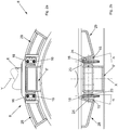
- each wedge 15 being arranged between the central structure 8' and a respective lateral structure 28, 29 and configured so as to be able to slide on sliding surfaces 23, 24 connected respectively to the central structure 8' and to the respective side structure 28, 29.
- a pair of spacers 71, 72 having essentially spherical-bowl shaped, reciprocally adjacent and joined surfaces, is provided between the central structure 8' and each wedge 15 ( Figure 2c ).
- the inner spacer 71 is integrally fixed to a side 75 of the central structure 8', e.g. by means of a pin 73.
- the outer spacer 72 is freely arranged between inner spacer 71 and a surface of the wedge 15 and defines, with its outermost flat surface with respect to the plane X-Y, the sliding surface 23 for a first surface 26 of the wedge 15 parallel to the side 75 of the central structure 8'.
- the innermost surface of the spacer 72 has a concave shape and perfectly mates the convex-shaped outermost surface of the spacer 71.
- Such a spacer 72 is locked during the step of assembling between spacer 71 and wedge 15 and it is the coupling between the spherical-bowl-shaped surfaces which maintains the position and does not allow it to be released from its seat
- said sliding surface 23 allows the wedge to slide and to absorb the expansions of the container 2.
- the coupling of the spherical-bowl shaped joined surfaces of the spacers 71 and 72 allows instead to absorb the movements of the container which could cause swerving of the container with respect to the ring.
- a further spacer 74 integrally fixed, e.g. by means of screws, to the lateral structure 29 is provided between the lateral structure 29 and each wedge 15 ( Figure 2c ) and defines, with its innermost flat surface with respect to the plane X-Y, the sliding surface 24 for a second surface 27 of the wedge 15 which is inclined with respect to said first surface 26 by a predetermined angle ⁇ , preferably comprised between 10 and 20°, preferably equal to approximately 15°.
- the surface 27 of the wedge 15 facing the sliding surface 24 is delimited by side protrusions 25 which laterally delimit the spacer 74 so that said spacer 74 acts as a guide for the sliding of the wedge.
- each wedge 15 is crossed by at least one tie-rod 16 connected thereto, preferably two tie-rods 16 as shown in Figure 2b , defining a longitudinal axis thereof, essentially parallel to axis X.
- the tie-rods 16 entirely cross the wedges 15 along a direction parallel to axis X.
- a first end of the tie-rods 16 is restrained to the wedge 15 during the step of assembling, e.g. by means of washers and tightening nuts, and the tie-rods 16 have a predetermined longitudinal extension so that they also cross the entire supporting ring 3.
- a second end of the tie-rods 16 is indeed arranged externally to the supporting ring 3 in proximity of a second surface 11 ( Figure 4 ) or 10 ( Figures 1 and 2d ) thereof opposite to the first surface 10 ( Figure 4 ) or 11 ( Figure 1 ).
- said second end of the tie-rods 16 is surrounded by a cylindrical shaped housing 18 containing elastic means 17, appropriately preloaded by means of the tightening nuts 76 during the step of assembling.
- the housing 18 is fixed with a base thereof onto the surface 10 ( Figure 1 ) or 11 ( Figure 4 ) of the ring 3.
- Said second end of the tie-rod crosses both the housing 18 and the elastic means 17 contained therein.
- a mobile closing plate 19 of the housing 18 is provided, arranged between the elastic means 17 and the tightening nuts 76 of the second end of the tie-rod, whereby the elastic means 17, preloaded during the step of assembling, extend by acting on the plate 19 allowing a translation of the tie-rod 16 and consequently a sliding of the wedge-shaped element 15 in a first direction, towards the ring 3, when clearances are produced between central structure 8' and lateral structures 28, 29 of the suspension device 8.
- the elastic means 17 comprise, for example Belleville washers or volute springs or helical springs with circular or square section wire or any other type of springs suitable to maintain the mechanical tension constant also in the presence of thermal stress and to allow to relieve a great force in very small spaces.
- the wedges 15 of the suspension devices 8 are thus maintained compressed whereby the suspension device is automatically adjusted as the expansions which are produced during the operation of the converter between central structure 8' and lateral structures 28, 29, i.e. between container 2 and supporting ring 3, vary.
- the elastic means which maintain the wedges 15 of the suspension devices 8 compressed do not comprise springs but are instead defined by the tie-rods 16 themselves which cross the wedges 15. In these cases, it is the elasticity of the tie-rod itself to maintain the mechanical tension constant also in the presence of thermal stress, and allow to relieve a high force even in very small spaces. The elasticity of the tie-rods 16 thus maintains the wedge-shaped elements compressed.
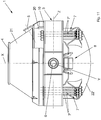
- Figures from 11 to 14 show a tilting converter, indicated by reference numeral 1' as a whole, comprising a second embodiment of a suspension device for the horizontal supporting of the converter object of the present invention.
- Such a converter 1' comprises all the features of the converter 1, described above, except for the fact that the zone 22' of the converter 2, containing the bottom of the container, is spherical-bowl-shaped and not conical frustum-shaped. Also in this case, the zone 22' of the container may alternatively have any appropriate geometry shape.
- the converter 1' is provided with at least two suspension devices 8 designed for horizontally supporting the converter according to a second variant of the invention.
- Such suspension devices 8 comprise:
- the lateral structures 28 and 29 are arranged essentially symmetric with respect to the central structure 8'.
- each wedge 15' being arranged between the central structure 8' and a respective lateral structure 28, 29 and configured so as to be able to slide on sliding surfaces 23, 24' connected respectively to the central structure 8' and to the respective side structure 28, 29.
- a pair of spacers 71, 72 having essentially spherical-bowl shaped, reciprocally adjacent and joined surfaces, is provided between the central structure 8' and each wedge 15' ( Figure 14 ).
- the description provided for the first embodiment of the suspension device applies to these spacers 71, 72.
- the sliding surface 23 allows in particular to absorb the expansions of the container 2.
- the coupling of the spherical-bowl shaped joined surfaces of the spacers 71 and 72 allows instead to absorb the movements of the container which could cause swerving of the container with respect to the ring.
- a further spacer 74' integrally fixed, e.g. by means of screws 80, to the lateral structure 29 is provided between the lateral structure 29 and each wedge 15' ( Figure 14 ) and defines, with its innermost flat surface with respect to the plane X-Y, the sliding surface 24' for a surface 27' of the wedge 15' which is inclined with respect to the surface 26 of the wedge 15', sliding on the sliding surface 23, by a predetermined angle ⁇ , preferably comprised between 10 and 20°, preferably equal to approximately 15°.
- the surface 27' of the wedge 15', facing the sliding surface 24', is delimited by side protrusions 25' which laterally delimit the spacer 74' whereby said spacer 74' acts as guide for the sliding of the wedge 15'.
- each wedge 15' is crossed by at least one respective tie-rod 16' connected thereto, preferably two tie-rods 16' as shown in Figure 14a , defining a longitudinal axis thereof, essentially parallel to axis X.
- the tie-rods 16' cross in this variant only one protrusion 81 of the portion of greater thickness of the wedge 15' ( Figure 14 ) and not the entire wedge 15'.
- the tie-rods 16' are provided in a fixed-end configuration within the spacer 74' ( Figures 14, 14a, 14b ) at a first end thereof and are therefore integrally fixed to the corresponding lateral structure 28 or 29.
- the elastic means 17 are connected to a second end of the tie-rods 16' and positioned in a housing 18' provided in a recess of the protrusion 81 of the wedge 15'.
- the elastic means 17 are preloaded during the step of assembling, and said second end of the tie-rod crosses both the cylindrical-shaped housing 18' and the elastic means 17 contained therein.
- a fixed closing plate 19' of the housing 18' is arranged between the elastic means 17 and the tightening nuts 76' of the second end of the tie-rod, whereby the elastic means 17, being the tie-rod fixed, extend acting on the wedge 15', determining a sliding in a first direction towards the surface 11 of the supporting ring 3. This occurs when clearances are produced between central structure 8' and lateral structures 28, 29 of the suspension device 8.
- the elastic means 17 may be, for example, Belleville washers or volute springs or helical springs with circular or square section wire or any other type of springs suitable to maintain the mechanical tension constant also in the presence of thermal stress and to allow to relieve a great force also in very small spaces.
- the wedges 15' of the suspension devices 8 are maintained compressed whereby the suspension device is automatically adjusted as the expansions, which are produced during the operation of the converter between central structure 8' and lateral structures 28, 29 during the operation of the converter, i.e. between container 2 and supporting ring 3, vary.
- the elastic means which maintain the wedges 15' of the suspension devices 8 compressed do not comprise springs but are instead defined by the tie-rods 16' themselves which cross the wedges 15'. In these cases, it is the elasticity of the tie-rod itself to maintain the mechanical tension constant also in the presence of thermal stress, and allow to relieve a high force even in very small spaces. The elasticity of the tie-rods 16' thus maintains the wedge-shaped elements compressed.
- the angle ⁇ defined by the wedges 15, 15' is greater than the friction angle, whereby there is always a free sliding of the wedges which allows in any condition to compensate clearances or prevent possible compression overloads between the parts fixed to the container and those fixed to the supporting ring.
- the action of the friction in all cases is essential when the converter is turned by 90° (position in Figure 9 ) because it prevents the load deriving from the weight of the container from weighing entirely on the tie-rods 16, 16' and on the elastic means 17.
- the suspension devices 7 for vertically supporting the converter are longitudinal bars 7' provided in a fixed-end configuration and restrained at a first end to the container 2 and at a second end to the supporting ring 3.
- the bars 7' are locked at the ends to prevent the presence of relative moving parts, and, as there are not parts subjected to wear, maintenance activities are cancelled or at least considerably reduced.
- the bars 7', acting as tie rods or struts, are adjustable to compensate for possible lack of uniformity of the bar length, thus guaranteeing a correct positioning thereof during assembly.
- Said bars are appropriately dimensioned to operate as elastic supporting means to absorb expansions.
- Said longitudinal bars 7' preferably have a circular section. However, other section shapes may by provided according to the designed longitudinal extension of the bars.
- the bars 7' are advantageously made of high-alloy steel, such as spring steel with high yield strength or other suitable steel with similar elasticity properties. Furthermore, the bars may be thermally treated (e.g. by means of hardening and tempering or solution heat-treatment according to the type of steel used) and may be provided with a surface coating, e.g. based on nickel, chrome or other suitable element.
- the high-quality material used allows to withstand very well not only mechanical stress but also oxidation which is very important in the context of oxygen converters.
- an advantageous configuration of the converter of the invention includes:
- Each suspension device 8 is provided in the space comprised between two groups of elastic bars 7' and is arranged in proximity of the first surface 10 of the ring 3 ( Figure 3 ). Alternatively, each suspension device 8 may be arranged near the second surface 11 of the ring ( Figures 1 and 11 ).
- the four groups of elastic bars 7' are arranged such that two pairs of groups of bars 7' are mutually arranged symmetrically with respect to the plane X-Y.
- Another advantageous configuration (not shown) of the converter includes two pairs of suspension devices 8, a first pair of suspension devices 8 being arranged at a first side of the plane Y-Z and a second pair of suspension devices 8 being arranged at a second side of the plane Y-Z. Furthermore, the suspension devices 8 are arranged symmetrically with respect to the plane X-Z. Considering the converter in vertical position, the bars 7' are arranged in vertical position while the suspension devices 8 are arranged in horizontal position. The bars 7' cross the plane Y-Z orthogonally. The suspension devices 8 are instead parallel to the plane Y-Z and cross the plane X-Y. In particular, one pair of suspension devices 8 is arranged at a first side of the plane Y-Z, i.e.
- the four groups of elastic bars 7' having four bars each, are mutually arranged at 90° to provide an isostatic balance, i.e. a balanced distribution of the loads for each group of elastic bars.
- the number of bars may be increased in the case of particularly high loads instead of designing thicker longitudinal elastic bars which would have lower elasticity.
- These groups of bars 7' are also essentially arranged mutually at 90° to continue to provide an isostatic balance. A higher number of thin bars would allow to distribute the load in optimal way, while maintaining a suitable elasticity of the bars.
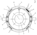
- All suspension devices 7, 8 are arranged, in plan view, essentially along a circumference ( Figures 3 and 12 ). They are thus essentially arranged along the side surface of a cylinder.
- the elastic bars 7' of the suspension devices 7 are restrained at an end to the container 2 by locking onto the fastening supports 14. They are instead restrained at the other end by locking directly onto the first surface 10 of the supporting ring 3.
- the restraint is a fixed-end configuration (fixed-end beam).
- Both the fastening surfaces 14, either welded or bolted to the container 2, and the first surface 10 of the ring 3 have through holes in which elastic bars 7' are inserted; the ends of such bars are threaded and they are locked onto the supports 14 and onto the first surface 10 of the ring by means of a self-aligning locking system and nuts, described below.
- the elastic bars 7' cross, with at least one end thereof, the cavity of the ring 3, optionally within a respective sleeve having the function of delimiting the passage channel of the respective bar 7'.
- a single fastening support 14 may be provided for each group of elastic bars 7'.
- the elastic bars 7' are fixed to the container 2 in a position underneath the supporting ring 3, i.e. underneath the plane Y-Z; while they are fixed to the ring 3 directly onto the first surface 10 thereof, i.e. above the plane Y-Z.
- the converter usually passes from a first position in which it is in its vertical position with the loading mouth 4 facing upwards ( Figure 1 ) to a second position inclined by approximately 30° with respect to the vertical 40 ( Figure 8 ), by means of a rotation of the supporting pins 6 in a sense of rotation.
- the cast iron and scrap is loaded through the mouth 4.
- the converter returns to the first position in Figure 1 after loading.
- One or more lances, introduced into the container through the mouth 4 blow oxygen for a given period of time so as to drastically lower the carbon content and reduce the concentration of impurities such as sulfur and phosphorus.
- the converter passes from the first position in Figure 1 to a third position ( Figure 9 ) inclined by approximately 90° with respect to the vertical 40, by means of the rotation of the supporting pins 6 in said sense of rotation.
- this third position the liquid steel is tapped through the tapping hole 5.
- the load determined by the sum of the weights of the container 2, the liquid cast iron and the scrap, is relieved onto the ground by means of the supporting ring 3, the elastic bars 7', the suspension devices 8, the tilting pins 6 and the respective supports.
- the configuration of the elastic bars 7' and of the suspension devices 8 allows to absorb the weight at any inclination of the container 2.
- the elastic bars 7' act exclusively as tie-rods for an inclination angle of the converter with respect to the vertical equal to 0°, while they acts only as struts for an inclination angle equal to 180°, and gradually both as tie-rods and as struts for different angles from 0° and 180°.
- the suspension devices 8 guarantee an optimal support, stability and rigidity of the container.
- the main purpose of said suspension devices 8 is to support the weight of the container in direction crosswise to axis Y when it is inclined by 90° (tapping position, e.g. Figure 9 ) and to support the load component orthogonal to axis X of the converter in all other conditions. These loads are mainly absorbed by the sliding surfaces 23, which allow in particular to absorb the expansions of the container 2.
- the suspension devices 8 also provide the function of preventing possible movements/oscillations on the horizontal plane when the converter is inclined by 90° for the step of tapping of the liquid steel.
- the load on the elastic bars 7' gradually passes from a maximum value with converter in vertical position to a zero value with converter in horizontal position, while the load on the suspension devices 8 passes gradually from zero to a maximum value when the converter passes from the horizontal position to the vertical position.
- a further advantage is that all the longitudinal elastic bars 7' are restrained in a fixed-end configuration and provided with an innovative self-aligning locking system at the two end supports for the axial closure and for compensating misalignments.
- both the fastening supports 14 and the inner and outer surfaces of the supporting ring 3 are generally made using low precision machine tools, they display machining errors with very approximate parallelism tolerances and/or shape irregularities. For this reason, the resting planes of the end supports of the bars 7' may not be perfectly parallel and thus converge.
- the outer resting surface 10 and the inner resting surface 10' of the first end support 60 ( Figure 4a ), belonging to the supporting ring 3 may not be perfectly parallel to each other, causing a discontinuous resting surface of the locking elements and subsequent clearances detrimental to wear resistance and stability of the tie-rod.
- the outer 40 and inner 40' resting surfaces of the second end support 60' may also display machining errors or shape irregularities. Furthermore, there may also be distance errors between the outer surface 10 of the end support 60 and the outer surface 40 of the end support 60'.
- Each tie-rod or strut of the suspension devices 7 of the converter of the invention comprises:
- the longitudinal bar 7' ( Figures 4a, 4b , 5 ) comprises a central portion 46, delimited on one side by a shoulder 52 and on the other side by an intermediate threaded portion 49, and two lateral portions 50, 51 having reciprocally different longitudinal extension along the axis X.
- the lateral portion 50 is arranged between the threaded end 47 and the corresponding shoulder 52 and has a longitudinal extension along the axis X essentially equal to the longitudinal extension of the hole 70 provided in the end support 60 ( Figure 4a ).
- the diameter of the lateral portion 50 is smaller than that of the adjacent threaded end 47.
- the lateral portion 51 instead, is arranged between the threaded end 48 and said threaded intermediate portion 49 and has a longitudinal extension along the axis X longer than the longitudinal extension of the lateral portion 50 and slightly longer than the sum of the longitudinal extensions of the three holes 80, 90, 90' ( Figure 4b ), provided in the respective end support 60' and in the two flanges 44, 45, respectively.
- the diameter of the lateral portion 51 is smaller than the diameter of the adjacent threaded ends 48 and of the intermediate threaded portion 49.
- the locking elements comprise at each end of the bar 7':
- each end support In a fixed-end tie rod configuration, the following are provided at each end support:
- the first pair of spacers and the corresponding second pair of spacers are arranged symmetrically with respect to the interposed end support, and the radius of the pair of joined surfaces 53, 54 of the first pair of spacers is equal to the spherical-bowl radius of the pair of joined surfaces 53', 54' of the second pair of spacers, said pair of joined surfaces being in all cases arranged on different spherical surfaces.
- Each longitudinal elastic bar 7' is clamped (non-spherical joint) by means of an innovative locking system to the two end supports for the axial closure and compensation of misalignments.
- Said at least two tightening nuts 41 are externally tightened onto the first pair of spacers 42, 43, i.e. onto the external pair of spacers.
- the clamping locking system of the elastic bar 7' includes at each of the treaded ends 47 and 48 of the bar ( Figure 4a ):
- a first end support 60 is provided with a hole 70 for the passage of a respective end of the bar ( Figure 4a ).
- the spacer 42' rests with a flat surface 55' thereof on the shoulder 52, while the spacer 43' rests with a flat surface 56' thereof on the inner surface 10' of the end support 60.
- the spacer 43 rests instead with a flat surface thereof 56 on the outer surface 10 of the end support 60, while the flat surface 55 of the spacer 42 is pressed by the tightening nuts 41.
- this clamping locking solution allows to compensate for misalignment errors of the surfaces 10, 10' by means of the sliding between the joined spherical-bowl shaped surfaces.
- the radius of the spherical-bowl shape is the same for both pairs of joined surfaces, but the centers are different, i.e. the two spherical-bowl shaped surfaces do not belong to the same spherical surface.
- this configuration of the spacers is a self-aligning "locked joint", i.e. a joint which cannot work as a ball joint but necessarily works as fixed joint when the bar is tightened.
- the spherical-bowl shaped joined surfaces allow a rotation during the step of assembly so that these surfaces also join with each other.
- the flat surfaces 56, 56' of the spacers 43, 43' are deformed following the tightening, so that the contact between said flat surfaces 56, 56' and the resting surfaces 10, 10' is maximized in order to obtain a continuous rest.
- this locking system allows to avoid the use of high accuracy machines and thus higher manufacturing and managing costs. Furthermore, advantageously, this locking system allows to use a supporting ring without any openings in its outer side surface, needed to access the tightening area in the case of state-of-the-art spherically jointed tie-rods, thus determining a greater mechanical resistance of the ring structure.
- the clamping locking system of the elastic bar 7' includes at the treaded end 48 of the bar ( Figure 4b ):
- the first flange 45 is arranged between the outer pair of spacers 42, 43 and the respective outer surface 40 of the end support 60' and a second flange 44 is arranged between the inner pair of spacers 42', 43' and the respective inner surface 40' of the end support 60'.
- the diameter of the hole 80 of the end support 60' is larger than the diameter of the hole 70 of the end support 60.
- the flanges 44, 45 are provided with respective holes 90, 90' of diameter smaller than the diameter of hole 80.
- the flanges 44 and 45 may consist of semi-flanges kept integral to each other by means of fastening means, such as for example stud bolts with nut and lock nut; alternatively, the outer flange is made in a single piece instead.
- the spacer 42' rests with a flat surface 55' thereof on the inner nut 41', while the spacer 43' rests with a flat surface 56' thereof on the flat surface of the inner flange 44.
- the spacer 43 rests instead with a flat surface thereof 56 on a flat surface of the outer flange 45, while the flat surface 55 of the spacer 42 is pressed by the outer tightening nuts 41.
- the inner tightening nut 41' is configured to be, in a fixed-end tie rod configuration, longer than length L of the useful part 200 of the thread of the intermediate threaded portion 49 protruding from the spacer 42' towards the inside of the bar 7'. This allows to avoid notching stress concentrations due to uncovered threads of the part subjected to bending of the bar itself. Once tightened, the inner nut 41' will thus have uncovered threads at the area in which the bar 7' tapers off towards the inside thereof.
- the fact of using the inner nut 41' allows to compensate for distance errors between resting surfaces, both those integral with the container and those integral with the supporting ring.
- the inner nut 41' is therefore an adjustment nut to compensate for these distance errors and to adapt the structure to the variable distances which may occur in design.
- the presence of the flanges 44 and 45, defining further spacers allows to maintain the hole 80 much larger than the diameter or thickness of the bar, thus assisting the passage of the bar and the assembly thereof onto the end supports.
- the alignment errors between the hole 70 of end support 60 and the hole 80 of end support 60' are also compensated.
Landscapes
- Engineering & Computer Science (AREA)
- Chemical & Material Sciences (AREA)
- Manufacturing & Machinery (AREA)
- Materials Engineering (AREA)
- Metallurgy (AREA)
- Organic Chemistry (AREA)
- Mechanical Engineering (AREA)
- General Engineering & Computer Science (AREA)
- Carbon Steel Or Casting Steel Manufacturing (AREA)
- Air Bags (AREA)
Description
- The present invention relates to a suspension device for tilting oxygen converter containers and to a converter provided with at least one pair of such suspension devices connecting the container to a supporting ring.
- The main object of an oxygen converter is to convert the cast iron produced in the blast furnace into raw liquid steel, which may be subsequently refined in the secondary steel production department.
- The main functions of the oxygen converter, also known as B.O.F. (Basic Oxygen Furnace), are to decarburize and remove phosphorous from the cast iron and to optimize the temperature of the steel so that further treatments may be carried out before casting with minimum heating and cooling of the steel.
- The exothermal oxidation reactions which are generated in the converter produce a great deal of thermal energy, more than that needed to reach the established temperature of the steel. This extra heat is used to melt ferrous material scrap and/or additions. The B.O.F. is substantially a furnace and thus subject to thermal expansion.
- The converter consists of a container, defining the reactor and having a substantially cylindrical shape, supported by a trunnion ring, surrounding the container and appropriately distanced therefrom, provided with two diametrical opposite supporting pins or trunnions, all supported by two supports anchored to the ground. The rotating control of the container is fitted onto one of the trunnions.
- An example of oxygen converter of the prior art is described in
WO9525818 - Movements are created on the horizontal plane between said two structures of the suspension devices, considering the converter in the vertical position thereof with the mouth facing upwards, because of the thermal expansions of the container and the supporting ring (due to the high temperatures which are generated inside the oven), and consequently of the respective structures connected thereto, said movements causing the creation of clearances or, in the case of compression between the two structures, overload of the parts due to excessive pressure.
- If clearance is created between the two structures, the container becomes mobile with respect to the supporting ring thus becoming unstable (in particular, during the rotation thereof), the structures of the suspension devices resting one upon the other on either side of the converter, giving rise to pulsing loads on the entire structure and to vibrations caused by shaking which occurs as a result of reactions happening inside.
- Instead, deformations in the shims or in the container which become permanent during cooling may occur in case of compression between the two structures.
- A further converter, disclosed in
US3653648 , is supported by an outer supporting ring and a plurality of suspension devices, each having a first anchor fixed to the container and a second anchor fixed directly to the supporting ring. A wedge-shaped shim, fixed in turn by means of screws during the step of assembling of the converter, allowing an adjustment of the suspension device exclusively during the step of assembling of the converter, is provided at the interface between the two anchors. Also in this case, pulsing loads occur in the entire structure, together with vibrations caused by shaking occurring as a result of the reactions happening inside, deformations of the shims or of the container which become permanent later on upon cooling. - The centering between container and supporting ring is also important to suitably allow deformations or thermal expansions of the container caused by the high temperatures reached during the conversion process.
- It is thus felt the need to make a suspension device for tilting converter containers and a respective tilting converter which allow to overcome the aforesaid drawbacks.
- It is a primary scope of the present invention to make a suspension and centering device for a tilting converter container, connecting said container to a supporting ring thereof, which allows both to compensate for thermal expansions, avoiding the creation of clearance between container, supporting ring and respective sliding shoes, and to avoid overloads in the interface zone between the part of the device fixed to the container and the parts of the device fixed to the supporting ring.
- Another object of the invention is to make a tilting converter in which the container suspension system, comprising horizontal and vertical suspension devices, is capable of maintaining an accurate centering without clearance between container and supporting ring in all steps of operation of the converter.
- A further object of the invention is to make a converter in which the suspension system can absorb the vibrations induced by the melting process.
- The present invention thus suggests to reach the objects above by making a suspension device for a tilting converter which, according to
claim 1, comprises a central structure, adapted to be fixed to a container of the converter; a first lateral structure, arranged at a first side of said central structure and adapted to be fixed to a first surface of a supporting ring of the container; a second lateral structure, arranged at a second side of said central structure, opposite said first side, and adapted to be fixed to said first surface of the supporting ring; wherein two wedge-shaped elements are provided, each wedge-shaped element being arranged between the central structure and a respective lateral structure and configured so as to slide on two sliding surfaces of the central structure and of the respective lateral structure, respectively; wherein each wedge-shaped element is crossed by at least one tie-rod connected thereto; and wherein elastic means associated to said at least one tie-rod or wherein said at least one tie-rod with its intrinsic elasticity are configured to produce a constant wedging of the wedge-shaped element whereby, when the suspension device is mounted to the container and to the supporting ring, an automatic adjustment of the suspension device occurs as the expansions produced between central structure and lateral structures vary during the operation of the converter. - Another aspect of the invention relates to a tilting converter which, according to
claim 11, comprises a container defining a first axis X; a supporting ring, coaxial to the container and spaced apart from said container, provided with two diametrically opposite supporting pins, defining a second axis Y orthogonal to the first axis X, adapted to allow the converter to rotate about said second axis; suspension devices, connecting said container to said supporting ring; wherein there are provided first suspension devices, comprising groups of elastic bars arranged parallel to the first axis X, said groups of bars being arranged substantially equally spaced apart from one another along said supporting ring; wherein there is provided at least one pair of second suspension devices according toclaim 1, in which the central structure is fixed to the container, the first lateral structure is fixed to a first surface of the supporting ring, and the second lateral structure is fixed to said first surface, said second suspension devices being each arranged at a respective trunnion and transversally to a first plane X-Y. - The suspension device, subject of the present invention, was designed to provide horizontal support to the converter, i.e. to support the loads when the converter assumes tapping position (
Figure 9 ). Such a horizontal suspension device has an innovative structure which compensates for expansions by virtue of the presence of wedge-shaped elements which are maintained always compressed by at least one respective tie-rod and springs, so that these wedge-shaped elements, being able to slide on sliding surfaces or guide blocks associated respectively to the part of the device fixed to the container and to parts fixed to the supporting ring, advance towards the supporting ring to occupy possible clearances or back, leaving space between the part fixed to the ring and the part fixed to the container, in case of excessive compression loads between said parts of the suspension device. - In this manner, when the suspension device of the invention is fitted on the container and on the supporting ring, the suspension device is automatically adjusted as the expansions which are produced between central structure and lateral structures of the device during operation of the converter, i.e. between converter and supporting ring, vary.
- In a first advantageous embodiment of the suspension device of the invention, the wedge-shaped elements are maintained wedged, i.e. maintained compressed, by means of at least one respective tie-rod which crosses the entire supporting ring.
- Considering the vertical configuration of the converter, i.e. with the mouth of the converter facing upwards, a first end of the tie-rod is restrained to the wedge-shaped element provided either underneath (
Figure 1 ) or above (Figures 3 and4 ) the supporting ring, while a second end of the tie-rod, provided with a housing containing the elastic means, is arranged either above (Figure 1 ) or underneath (Figures 3 and4 ) the supporting ring. The device is configured so that the elastic means, appropriately preloaded during the step of assembling, work on the second end of the tie-rod causing, as a consequence, a sliding of the respective wedge-shaped element if clearance is created between container and supporting ring. - In a second advantageous embodiment of the suspension device of the invention, each tie-rod is integrally fixed, at a first end thereof, to the corresponding lateral structure of the suspension device, and the elastic means are restrained to a second end of the tie-rod and positioned in a housing provided in a recess of the wedge-shaped element whereby the elastic means act directly on the wedge-shaped element causing it to slide and to be wedged in if clearance is created between container and supporting ring.
- Preferably, two wedge-shaped elements are provided for each suspension device of the invention, one for each interface between the structure fixed to the container and the structures fixed to the ring, each wedge-shaped element being crossed by two tie-rods.
- A preferred, but not exclusive, embodiment of a tilting converter comprises:
- at least two suspension devices, according to the present invention, for the horizontal supporting of the converter, each arranged near a respective supporting pin, either above or underneath the supporting ring;
- and four groups of elastic bars provided in a fixed-end configuration to vertically support the converter, i.e. when the converter has the container with mouth facing either upwards or downwards.
- A variant of the converter may be provided, comprising:
- four suspension devices, according to the present invention, for horizontal supporting of the converter; a first pair of such devices being arranged above the supporting ring and a second pair being arranged below said ring;
- and four groups of elastic bars provided in a fixed-end configuration to vertically support the converter.
- The groups of elastic bars contain a variable number of bars from two to six, preferably four.
- The structure of the converter obtained as a whole is compact, solid and adaptable to the working conditions of the furnace or converter.
- The elastic means are, for example, Belleville washers, which maintain the mechanical tension constant also in the presence of thermal stress and allow to relieve a high force even in very small spaces. Volute springs, helical springs with round or square section wire or any other type of springs suited to the purpose may alternatively be used.
- In all the embodiments of the invention, the elastic means may be constituted by the same tie-rods which cross the wedge-shaped elements, alternatively to springs. In these cases, it is the elasticity of the tie-rod itself which maintains the mechanical tension constant also in the presence of thermal stress and allows to relieve a high force even in very small spaces. The elasticity of the tie-rods thus maintains the wedging of the wedge-shaped elements, i.e. produces a constant wedging of said wedge-shaped elements to maintain them compressed.
- In particular, the suspension device of the converter object of the present invention has the following advantages:
- it allows to easily absorb the thermal expansions of the container;
- it effectively absorbs the vibrations which are generated during blowing of oxygen into the container, as a virtue of a constant compensation of the clearances;
- it effectively absorbs the forces generated by the inertia of the container at the beginning and end of its rotation;
- it maintains the container centered with respect to the supporting ring with high accuracy in all conditions of inclination;
- it is extremely simple to assemble;
- it allows even irregular expansions of the structure without inducing any overload of the mechanical parts.
- The excellent centering between container and supporting ring allows the thermal expansions of the container caused by the high temperatures reached during the conversion process without any interference between container and supporting ring.
- The suspension device of the converter, object of the present invention, further allows to fulfill the common requirement of all converters, i.e. that the entire structure of the converter, including protrusions, must be configured so as to be inscribed within a sphere (
Figure 1 ) the radius of which is determined by layout requirements of the plant comprising the converter. - The dependent claims describe preferred embodiments of the invention.
- Further features and advantages of the present invention will be more apparent in the light of the detailed description of a preferred, but not exclusive, embodiment of a suspension device and of a tilting converter illustrated by way of non-limitative example, with reference to the accompanying drawings, in which:
-
Figure 1 shows a side view of a first embodiment of an oxygen converter according to the invention, in a vertical melting position, with the horizontal suspension devices provided underneath the supporting ring; -
Figure 2a shows a bottom section view of a first embodiment of a suspension device according to the invention; -
Figure 2b shows a side section view of the suspension device inFigure 2a ; -
Figure 2c shows an enlargement of a part inFigure 2a ; -
Figure 2d shows an enlarged section view of part C inFigure 1 ; -
Figure 3 shows a top view of a variant of the converter inFigure 1 , with the horizontal suspension devices provided above the supporting ring; -
Figure 4 shows a partially sectioned side view of the converter inFigure 3 ; -
Figure 4a shows an enlarged section view of a first part inFigure 4 ; -
Figure 4b shows an enlarged section view of a second part inFigure 4 ; -
Figure 5 shows an exploded perspective view of a component of the converter according to the invention; -
Figures 6 and 7 show side and perspective exploded views, respectively, of some elements of the component ofFigure 5 ; -
Figure 8 shows the converter inFigure 1 in a first operative position of loading cast iron and scrap; -
Figure 9 shows the converter inFigure 1 in a second operative steel tapping position; -
Figure 10 shows the converter inFigure 1 in a third operative slag unloading position; -
Figure 11 shows a side view of a second embodiment of an oxygen converter according to the invention in a vertical melting position; -
Figure 12 shows a bottom view of the converter inFigure 11 ; -
Figure 13a is a bottom partially sectioned view of a second embodiment of a suspension device according to the invention; -
Figure 13b shows a partially sectioned side view of the suspension device inFigure 13a ; -
Figure 14 shows an enlarged section view of part of the device inFigure 13b ; -
Figure 14a shows a section view taken along the plane A-A of part of the device inFigure 14 ; -
Figure 14b shows a section view taken along plane B-B of the part shown inFigure 14a . - The same reference numbers in the figures identify the same elements.
- Figures from 1 to 10 show a tilting converter, indicated by
reference numeral 1 as a whole, comprising a first embodiment of a suspension device for the horizontal support of the converter, object of the present invention. - Such a
converter 1 comprises: - a container or
tank 2, defining an axis X, provided with aloading mouth 4 of the scrap and liquid cast iron and provided with alateral tapping hole 5 of the liquid steel obtained at the end of the conversion process; - a supporting
ring 3 for supporting thecontainer 2, saidring 3 being arranged coaxially to thecontainer 2 and appropriately distanced therefrom; - two supporting pins or tilting
pins 6 of said supportingring 3, known as trunnions, arranged diametrically opposite to each other and defining an axis Y, orthogonal to axis X, with at least one of said supportingpins 6 connected to a tilting mechanism (not shown); - the
suspension devices container 2 to the supportingring 3 and which also perform a centering function between container and ring. - A plane Y-Z, which may be considered "equatorial" of the converter, and a plane X-Z, both orthogonal to the plane X-Y, are identified defining a further axis Z as axis orthogonal to the plane X-Y and passing through the intersection point of axes X and Y.
- The
container 2, in the non-limitative example ofFigures 1 and4 , comprises a cylindricalcentral zone 20 and two conical frustum-shapedzones zone 21 is welded at an end to said centralcylindrical zone 20 while the other end comprises theloading mouth 4 of the container. A second conical frustum-shapedzone 22 is welded at an end to said cylindricalcentral zone 20, on the opposite side to the first conical frustum-shapedzone 21, while the other end comprises the bottom 2' of thecontainer 2. - Other examples of container may have a shape other than conical frustum in said second zone, e.g. a spherical-bowl shape or other appropriate geometric shape.
- The supporting
ring 3, arranged at thecentral zone 20 of thecontainer 2, is empty and preferably has a rectangular cross section. Thering 3 has afirst surface 10 facing towards the part of the container comprising theloading mouth 4; asecond surface 11, opposite to thesurface 10, facing the part of thecontainer 2 comprising the bottom 2' thereof; a third inner surface facing the central part of the container; a fourth outer surface opposite to the inner surface. - Advantageously, the
converter 1 is provided with at least twosuspension devices 8 designed for horizontally supporting the converter according to a first variant of the invention. -
Such suspension devices 8 comprise: - a central structure 8' fixed, for example by welding, to the
container 2 of theconverter 1, - a first
lateral structure 28 arranged at a first side of said central structure 8' and fixed, for example by welding, onto a first surface 10 (Figures 3 and4 ) or 11 (Figure 1 ) of the supportingring 3 of the container, - a second
lateral structure 29 arranged at a second side of said central structure 8', opposite to the first side, and fixed, for example by welding, onto said first surface 10 (Figures 3 and4 ) or 11 (Figure 1 ) of the supportingring 3. - The
lateral structures - Advantageously, two wedge-shaped
elements 15, or simplywedges 15, are provided, eachwedge 15 being arranged between the central structure 8' and a respectivelateral structure surfaces respective side structure - A pair of
spacers Figure 2c ). Theinner spacer 71 is integrally fixed to aside 75 of the central structure 8', e.g. by means of apin 73. Theouter spacer 72 is freely arranged betweeninner spacer 71 and a surface of thewedge 15 and defines, with its outermost flat surface with respect to the plane X-Y, the slidingsurface 23 for afirst surface 26 of thewedge 15 parallel to theside 75 of the central structure 8'. The innermost surface of thespacer 72 has a concave shape and perfectly mates the convex-shaped outermost surface of thespacer 71. Such aspacer 72 is locked during the step of assembling betweenspacer 71 andwedge 15 and it is the coupling between the spherical-bowl-shaped surfaces which maintains the position and does not allow it to be released from its seat. - In particular, said sliding
surface 23 allows the wedge to slide and to absorb the expansions of thecontainer 2. The coupling of the spherical-bowl shaped joined surfaces of thespacers - A
further spacer 74 integrally fixed, e.g. by means of screws, to thelateral structure 29 is provided between thelateral structure 29 and each wedge 15 (Figure 2c ) and defines, with its innermost flat surface with respect to the plane X-Y, the slidingsurface 24 for asecond surface 27 of thewedge 15 which is inclined with respect to saidfirst surface 26 by a predetermined angle α, preferably comprised between 10 and 20°, preferably equal to approximately 15°. - In particular, the
surface 27 of thewedge 15 facing the slidingsurface 24 is delimited byside protrusions 25 which laterally delimit thespacer 74 so that said spacer 74 acts as a guide for the sliding of the wedge. - Advantageously, each
wedge 15 is crossed by at least one tie-rod 16 connected thereto, preferably two tie-rods 16 as shown inFigure 2b , defining a longitudinal axis thereof, essentially parallel to axis X. The tie-rods 16 entirely cross thewedges 15 along a direction parallel to axis X. - A first end of the tie-
rods 16 is restrained to thewedge 15 during the step of assembling, e.g. by means of washers and tightening nuts, and the tie-rods 16 have a predetermined longitudinal extension so that they also cross the entire supportingring 3. - A second end of the tie-
rods 16 is indeed arranged externally to the supportingring 3 in proximity of a second surface 11 (Figure 4 ) or10 (Figures 1 and2d ) thereof opposite to the first surface 10 (Figure 4 ) or11 (Figure 1 ). - In a first variant of said first embodiment, said second end of the tie-
rods 16 is surrounded by a cylindrical shapedhousing 18 containing elastic means 17, appropriately preloaded by means of the tighteningnuts 76 during the step of assembling. Thehousing 18 is fixed with a base thereof onto the surface 10 (Figure 1 ) or11 (Figure 4 ) of thering 3. - Said second end of the tie-rod crosses both the
housing 18 and the elastic means 17 contained therein. Amobile closing plate 19 of thehousing 18 is provided, arranged between the elastic means 17 and the tighteningnuts 76 of the second end of the tie-rod, whereby the elastic means 17, preloaded during the step of assembling, extend by acting on theplate 19 allowing a translation of the tie-rod 16 and consequently a sliding of the wedge-shapedelement 15 in a first direction, towards thering 3, when clearances are produced between central structure 8' andlateral structures suspension device 8. - On the other hand, when compression overloads are produced between central structure 8' and one of the
lateral structures wedge 15, and thus the tie-rods 16, will tend to slide in a second direction, opposite to said first direction, and theplate 19 will press the elastic means 17 inside thehousing 18. The elastic means 17 comprise, for example Belleville washers or volute springs or helical springs with circular or square section wire or any other type of springs suitable to maintain the mechanical tension constant also in the presence of thermal stress and to allow to relieve a great force in very small spaces. - The
wedges 15 of thesuspension devices 8 are thus maintained compressed whereby the suspension device is automatically adjusted as the expansions which are produced during the operation of the converter between central structure 8' andlateral structures container 2 and supportingring 3, vary. - In a second variant of said first embodiment, the elastic means which maintain the
wedges 15 of thesuspension devices 8 compressed do not comprise springs but are instead defined by the tie-rods 16 themselves which cross thewedges 15. In these cases, it is the elasticity of the tie-rod itself to maintain the mechanical tension constant also in the presence of thermal stress, and allow to relieve a high force even in very small spaces. The elasticity of the tie-rods 16 thus maintains the wedge-shaped elements compressed. - Figures from 11 to 14 show a tilting converter, indicated by reference numeral 1' as a whole, comprising a second embodiment of a suspension device for the horizontal supporting of the converter object of the present invention.
- Such a converter 1' comprises all the features of the
converter 1, described above, except for the fact that the zone 22' of theconverter 2, containing the bottom of the container, is spherical-bowl-shaped and not conical frustum-shaped. Also in this case, the zone 22' of the container may alternatively have any appropriate geometry shape. - Advantageously, the converter 1' is provided with at least two
suspension devices 8 designed for horizontally supporting the converter according to a second variant of the invention. -
Such suspension devices 8 comprise: - a central structure 8' fixed, for example by welding, to the
container 2 of theconverter 1, - a
first side structure 28, arranged at a first side of said central structure 8', and fixed, for example by welding, to thesecond surface 11 of a supportingring 3 of the container, - a
second side structure 29 arranged at a second side of said central structure 8', opposite to the first side, and fixed, e.g. by welding, to saidsecond surface 11 of thering 3. - The
lateral structures - Advantageously, two wedge-shaped elements 15', or simply wedges 15', are provided, each wedge 15' being arranged between the central structure 8' and a respective
lateral structure surfaces 23, 24' connected respectively to the central structure 8' and to therespective side structure - A pair of
spacers Figure 14 ). The description provided for the first embodiment of the suspension device applies to thesespacers - Also in the case of this variant, the sliding
surface 23 allows in particular to absorb the expansions of thecontainer 2. The coupling of the spherical-bowl shaped joined surfaces of thespacers - A further spacer 74' integrally fixed, e.g. by means of
screws 80, to thelateral structure 29 is provided between thelateral structure 29 and each wedge 15' (Figure 14 ) and defines, with its innermost flat surface with respect to the plane X-Y, the sliding surface 24' for a surface 27' of the wedge 15' which is inclined with respect to thesurface 26 of the wedge 15', sliding on the slidingsurface 23, by a predetermined angle α, preferably comprised between 10 and 20°, preferably equal to approximately 15°. - In particular, the surface 27' of the wedge 15', facing the sliding surface 24', is delimited by side protrusions 25' which laterally delimit the spacer 74' whereby said spacer 74' acts as guide for the sliding of the wedge 15'.
- Advantageously, each wedge 15' is crossed by at least one respective tie-rod 16' connected thereto, preferably two tie-rods 16' as shown in
Figure 14a , defining a longitudinal axis thereof, essentially parallel to axis X. The tie-rods 16' cross in this variant only oneprotrusion 81 of the portion of greater thickness of the wedge 15' (Figure 14 ) and not the entire wedge 15'. - The tie-rods 16' are provided in a fixed-end configuration within the spacer 74' (
Figures 14, 14a, 14b ) at a first end thereof and are therefore integrally fixed to the correspondinglateral structure - In a first variant of said second embodiment, the elastic means 17 are connected to a second end of the tie-rods 16' and positioned in a housing 18' provided in a recess of the
protrusion 81 of the wedge 15'. The elastic means 17 are preloaded during the step of assembling, and said second end of the tie-rod crosses both the cylindrical-shaped housing 18' and the elastic means 17 contained therein. - A fixed closing plate 19' of the housing 18' is arranged between the elastic means 17 and the tightening nuts 76' of the second end of the tie-rod, whereby the elastic means 17, being the tie-rod fixed, extend acting on the wedge 15', determining a sliding in a first direction towards the
surface 11 of the supportingring 3. This occurs when clearances are produced between central structure 8' andlateral structures suspension device 8. - Vice versa, when compression overloads are produced between central structure 8' and one of the
lateral structures - Therefore, also in this second embodiment, the wedges 15' of the
suspension devices 8 are maintained compressed whereby the suspension device is automatically adjusted as the expansions, which are produced during the operation of the converter between central structure 8' andlateral structures container 2 and supportingring 3, vary. - In a second variant of said second embodiment, the elastic means which maintain the wedges 15' of the
suspension devices 8 compressed do not comprise springs but are instead defined by the tie-rods 16' themselves which cross the wedges 15'. In these cases, it is the elasticity of the tie-rod itself to maintain the mechanical tension constant also in the presence of thermal stress, and allow to relieve a high force even in very small spaces. The elasticity of the tie-rods 16' thus maintains the wedge-shaped elements compressed. - Advantageously, in both embodiments of the
suspension device 8, object of the present invention, the angle α defined by thewedges 15, 15' is greater than the friction angle, whereby there is always a free sliding of the wedges which allows in any condition to compensate clearances or prevent possible compression overloads between the parts fixed to the container and those fixed to the supporting ring. The action of the friction in all cases is essential when the converter is turned by 90° (position inFigure 9 ) because it prevents the load deriving from the weight of the container from weighing entirely on the tie-rods 16, 16' and on theelastic means 17. - A further advantage is represented in that in the converter of the invention, in all embodiments thereof, the
suspension devices 7 for vertically supporting the converter are longitudinal bars 7' provided in a fixed-end configuration and restrained at a first end to thecontainer 2 and at a second end to the supportingring 3. The bars 7' are locked at the ends to prevent the presence of relative moving parts, and, as there are not parts subjected to wear, maintenance activities are cancelled or at least considerably reduced. The bars 7', acting as tie rods or struts, are adjustable to compensate for possible lack of uniformity of the bar length, thus guaranteeing a correct positioning thereof during assembly. - Said bars are appropriately dimensioned to operate as elastic supporting means to absorb expansions.
- Said longitudinal bars 7' preferably have a circular section. However, other section shapes may by provided according to the designed longitudinal extension of the bars.
- The bars 7' are advantageously made of high-alloy steel, such as spring steel with high yield strength or other suitable steel with similar elasticity properties. Furthermore, the bars may be thermally treated (e.g. by means of hardening and tempering or solution heat-treatment according to the type of steel used) and may be provided with a surface coating, e.g. based on nickel, chrome or other suitable element. The high-quality material used allows to withstand very well not only mechanical stress but also oxidation which is very important in the context of oxygen converters.
- With reference to
Figure 3 and12 , an advantageous configuration of the converter of the invention includes: - four groups of elastic bars 7' arranged parallel to axis X and at an equal angular distance between one group and the next (90°);
- a pair of
suspension devices 8, saidsuspension devices 8 being arranged each at a respective supportingpin 6, symmetrically with respect to the plane X-Z on a respective plane parallel to plane Y-Z. - Each
suspension device 8 is provided in the space comprised between two groups of elastic bars 7' and is arranged in proximity of thefirst surface 10 of the ring 3 (Figure 3 ). Alternatively, eachsuspension device 8 may be arranged near thesecond surface 11 of the ring (Figures 1 and11 ). - The four groups of elastic bars 7' are arranged such that two pairs of groups of bars 7' are mutually arranged symmetrically with respect to the plane X-Y.
- Another advantageous configuration (not shown) of the converter includes two pairs of
suspension devices 8, a first pair ofsuspension devices 8 being arranged at a first side of the plane Y-Z and a second pair ofsuspension devices 8 being arranged at a second side of the plane Y-Z. Furthermore, thesuspension devices 8 are arranged symmetrically with respect to the plane X-Z. Considering the converter in vertical position, the bars 7' are arranged in vertical position while thesuspension devices 8 are arranged in horizontal position. The bars 7' cross the plane Y-Z orthogonally. Thesuspension devices 8 are instead parallel to the plane Y-Z and cross the plane X-Y. In particular, one pair ofsuspension devices 8 is arranged at a first side of the plane Y-Z, i.e. above the plane Y-Z and the supportingring 3 when the converter is in vertical or straight position; while another pair of the suspension devices 8 (not shown) is arranged at a second side of the plane Y-Z, i.e. below the plane Y-Z and the supportingring 3 when the converter is in the vertical or straight position. - In the variants shown in the Figures, the four groups of elastic bars 7', having four bars each, are mutually arranged at 90° to provide an isostatic balance, i.e. a balanced distribution of the loads for each group of elastic bars.
- The number of bars may be increased in the case of particularly high loads instead of designing thicker longitudinal elastic bars which would have lower elasticity. These groups of bars 7' are also essentially arranged mutually at 90° to continue to provide an isostatic balance. A higher number of thin bars would allow to distribute the load in optimal way, while maintaining a suitable elasticity of the bars.
- All
suspension devices Figures 3 and12 ). They are thus essentially arranged along the side surface of a cylinder. - The elastic bars 7' of the
suspension devices 7 are restrained at an end to thecontainer 2 by locking onto the fastening supports 14. They are instead restrained at the other end by locking directly onto thefirst surface 10 of the supportingring 3. The restraint is a fixed-end configuration (fixed-end beam). Both the fastening surfaces 14, either welded or bolted to thecontainer 2, and thefirst surface 10 of thering 3 have through holes in which elastic bars 7' are inserted; the ends of such bars are threaded and they are locked onto thesupports 14 and onto thefirst surface 10 of the ring by means of a self-aligning locking system and nuts, described below. The elastic bars 7' cross, with at least one end thereof, the cavity of thering 3, optionally within a respective sleeve having the function of delimiting the passage channel of the respective bar 7'. Advantageously, asingle fastening support 14 may be provided for each group of elastic bars 7'. - With reference to
Figures 1 and11 (converter in vertical position), the elastic bars 7' are fixed to thecontainer 2 in a position underneath the supportingring 3, i.e. underneath the plane Y-Z; while they are fixed to thering 3 directly onto thefirst surface 10 thereof, i.e. above the plane Y-Z. - The two supporting
pins 6, actuated by at least one tilting mechanism, allow the rotation of the converter about axis Y. - The converter usually passes from a first position in which it is in its vertical position with the
loading mouth 4 facing upwards (Figure 1 ) to a second position inclined by approximately 30° with respect to the vertical 40 (Figure 8 ), by means of a rotation of the supportingpins 6 in a sense of rotation. In the position inFigure 8 , the cast iron and scrap is loaded through themouth 4. The converter returns to the first position inFigure 1 after loading. One or more lances, introduced into the container through themouth 4, blow oxygen for a given period of time so as to drastically lower the carbon content and reduce the concentration of impurities such as sulfur and phosphorus. Once the conversion into liquid raw steel has been completed, the converter passes from the first position inFigure 1 to a third position (Figure 9 ) inclined by approximately 90° with respect to the vertical 40, by means of the rotation of the supportingpins 6 in said sense of rotation. In this third position, the liquid steel is tapped through thetapping hole 5. - In all variants of the invention, shown in the Figures, the load, determined by the sum of the weights of the
container 2, the liquid cast iron and the scrap, is relieved onto the ground by means of the supportingring 3, the elastic bars 7', thesuspension devices 8, the tilting pins 6 and the respective supports. - In particular, the configuration of the elastic bars 7' and of the
suspension devices 8 allows to absorb the weight at any inclination of thecontainer 2. - The elastic bars 7' act exclusively as tie-rods for an inclination angle of the converter with respect to the vertical equal to 0°, while they acts only as struts for an inclination angle equal to 180°, and gradually both as tie-rods and as struts for different angles from 0° and 180°.
- The position with inclination angle equal to 180°, shown in
Figure 10 , with theloading mouth 4 facing downwards, is provided for cleaning operations of the container once emptied. - The
suspension devices 8 guarantee an optimal support, stability and rigidity of the container. The main purpose of saidsuspension devices 8 is to support the weight of the container in direction crosswise to axis Y when it is inclined by 90° (tapping position, e.g.Figure 9 ) and to support the load component orthogonal to axis X of the converter in all other conditions. These loads are mainly absorbed by the slidingsurfaces 23, which allow in particular to absorb the expansions of thecontainer 2. - The
suspension devices 8 also provide the function of preventing possible movements/oscillations on the horizontal plane when the converter is inclined by 90° for the step of tapping of the liquid steel. - In general, the load on the elastic bars 7' gradually passes from a maximum value with converter in vertical position to a zero value with converter in horizontal position, while the load on the
suspension devices 8 passes gradually from zero to a maximum value when the converter passes from the horizontal position to the vertical position. - The moments which are generated with the rotation of the converter about axis Y are perfectly absorbed by the embodiments of
suspension devices spacers - A further advantage is that all the longitudinal elastic bars 7' are restrained in a fixed-end configuration and provided with an innovative self-aligning locking system at the two end supports for the axial closure and for compensating misalignments.
- As both the fastening supports 14 and the inner and outer surfaces of the supporting
ring 3 are generally made using low precision machine tools, they display machining errors with very approximate parallelism tolerances and/or shape irregularities. For this reason, the resting planes of the end supports of the bars 7' may not be perfectly parallel and thus converge. - For example, taking the ends of the bars 7' (
Figures 4a and 4b ) into account, theouter resting surface 10 and the inner resting surface 10' of the first end support 60 (Figure 4a ), belonging to the supportingring 3, may not be perfectly parallel to each other, causing a discontinuous resting surface of the locking elements and subsequent clearances detrimental to wear resistance and stability of the tie-rod. - The outer 40 and inner 40' resting surfaces of the second end support 60' (
Figure 4b ), part of thefastening support 14, may also display machining errors or shape irregularities. Furthermore, there may also be distance errors between theouter surface 10 of theend support 60 and theouter surface 40 of the end support 60'. - Each tie-rod or strut of the
suspension devices 7 of the converter of the invention comprises: - a longitudinal elastic bar 7', provided with threaded ends 47, 48;
- locking elements to lock the ends of the bar to respective end supports 60, 60';
- a pair of flanges or resting
shims flanges - The longitudinal bar 7' (
Figures 4a, 4b ,5 ) comprises acentral portion 46, delimited on one side by ashoulder 52 and on the other side by an intermediate threadedportion 49, and twolateral portions - The
lateral portion 50 is arranged between the threadedend 47 and thecorresponding shoulder 52 and has a longitudinal extension along the axis X essentially equal to the longitudinal extension of thehole 70 provided in the end support 60 (Figure 4a ). The diameter of thelateral portion 50 is smaller than that of the adjacent threadedend 47. - The
lateral portion 51, instead, is arranged between the threadedend 48 and said threadedintermediate portion 49 and has a longitudinal extension along the axis X longer than the longitudinal extension of thelateral portion 50 and slightly longer than the sum of the longitudinal extensions of the threeholes Figure 4b ), provided in the respective end support 60' and in the twoflanges lateral portion 51 is smaller than the diameter of the adjacent threaded ends 48 and of the intermediate threadedportion 49. - The locking elements comprise at each end of the bar 7':
- two pairs of
spacers Figures 6 e7 ); - and at least two tightening nuts 41.
- In a fixed-end tie rod configuration, the following are provided at each end support:
- a first pair of
spacers - a second pair of spacers 42', 43' arranged at an internal side of the respective end support.
- Advantageously, the first pair of spacers and the corresponding second pair of spacers are arranged symmetrically with respect to the interposed end support, and the radius of the pair of joined
surfaces - Said at least two tightening
nuts 41 are externally tightened onto the first pair ofspacers - In particular, with reference to
Figures 4a and5 , the clamping locking system of the elastic bar 7' includes at each of the treaded ends 47 and 48 of the bar (Figure 4a ): - outer tightening
nuts 41, e.g. in a minimum number of two, to be tightened to the threadedend 14 of the bar 7'; - a first outer pair of spacers or
washers nuts 41 and theouter surface 10 of theend support 60; eachspacer respective hole bar 47, thespacer 43 having a surface of annular portion ofspherical bowl 53 joined to acorresponding surface 54 provided in the spacer 42 (Figures 6 and 7 ); - a second inner pair of spacers or washers 42', 43', to be arranged between the
shoulder 52 of the bar 7' and the inner surface 10' of theend support 60; each spacer 42', 43' being provided with a respective hole 61', 62' for the passage of the threaded end of thebar 47, the spacer 43' having a surface of annular portion of spherical bowl 53' joined to a corresponding surface 54' provided in the spacer 42' (Figures 6 and 7 ). - A
first end support 60 is provided with ahole 70 for the passage of a respective end of the bar (Figure 4a ). - With reference to
Figures 4a ,5 ,6 and 7 , the spacer 42' rests with a flat surface 55' thereof on theshoulder 52, while the spacer 43' rests with a flat surface 56' thereof on the inner surface 10' of theend support 60. Thespacer 43 rests instead with a flat surface thereof 56 on theouter surface 10 of theend support 60, while theflat surface 55 of thespacer 42 is pressed by the tightening nuts 41. - Tightening the nuts 41 on the threaded
end 47 of the bar 7' the joined surfaces 53', 54' of the spacers 43', 42' and the joined surfaces 53, 54 of thespacers flat surfaces 56, 56' adapt to the shape of therespective surfaces 10, 10' of theend support 60. - Advantageously, this clamping locking solution allows to compensate for misalignment errors of the
surfaces 10, 10' by means of the sliding between the joined spherical-bowl shaped surfaces. The radius of the spherical-bowl shape is the same for both pairs of joined surfaces, but the centers are different, i.e. the two spherical-bowl shaped surfaces do not belong to the same spherical surface. As a consequence, this configuration of the spacers is a self-aligning "locked joint", i.e. a joint which cannot work as a ball joint but necessarily works as fixed joint when the bar is tightened. - The spherical-bowl shaped joined surfaces allow a rotation during the step of assembly so that these surfaces also join with each other. The flat surfaces 56, 56' of the
spacers 43, 43' are deformed following the tightening, so that the contact between saidflat surfaces 56, 56' and the resting surfaces 10, 10' is maximized in order to obtain a continuous rest. - The use of this locking system allows to avoid the use of high accuracy machines and thus higher manufacturing and managing costs. Furthermore, advantageously, this locking system allows to use a supporting ring without any openings in its outer side surface, needed to access the tightening area in the case of state-of-the-art spherically jointed tie-rods, thus determining a greater mechanical resistance of the ring structure.
- Instead, with reference to
Figures 4a and5 , the clamping locking system of the elastic bar 7' includes at thetreaded end 48 of the bar (Figure 4b ): - outer tightening
nuts 41, e.g. in a minimum number of two, to be tightened onto the threadedend 48; - two
flanges - a first outer pair of spacers or
washers nuts 41 and theouter flange 45; eachspacer respective hole end 48 of the bar 7', thespacer 43 having anannular portion surface 53 of spherical-bowl joined to acorresponding surface 54 provided in the spacer 42 (Figures 6 and 7 ); - a second inner pair of spacers or washers 42', 43', to be arranged between the
inner flange 44 and the inner nut 41'; eachspacer end 48 of the bar 7', the spacer 43' having an annular portion surface 53' of spherical-bowl joined to a corresponding surface 54' provided in the spacer 42'; - an inner nut 41' to be tightened onto the intermediate threaded
portion 49 to abut on the inner pair of spacers 42', 43'. - The
first flange 45 is arranged between the outer pair ofspacers outer surface 40 of the end support 60' and asecond flange 44 is arranged between the inner pair of spacers 42', 43' and the respective inner surface 40' of the end support 60'. - The diameter of the
hole 80 of the end support 60' is larger than the diameter of thehole 70 of theend support 60. Theflanges respective holes 90, 90' of diameter smaller than the diameter ofhole 80. Theflanges - With reference to
Figures 4b ,6 and 7 , the spacer 42' rests with a flat surface 55' thereof on the inner nut 41', while the spacer 43' rests with a flat surface 56' thereof on the flat surface of theinner flange 44. Thespacer 43 rests instead with a flat surface thereof 56 on a flat surface of theouter flange 45, while theflat surface 55 of thespacer 42 is pressed by the outer tightening nuts 41. - Tightening the nuts 41 on the threaded
end 48 of the bar 7' and tightening the inner nut 41' on the intermediate threadedportion 49, the joined surfaces 53', 54' of the spacers 43', 42' and the joined surfaces 53, 54 of thespacers flat surfaces 56, 56' press on theflanges respective surfaces 40, 40' of the end support 60'. - Advantageously, the inner tightening nut 41' is configured to be, in a fixed-end tie rod configuration, longer than length L of the
useful part 200 of the thread of the intermediate threadedportion 49 protruding from the spacer 42' towards the inside of the bar 7'. This allows to avoid notching stress concentrations due to uncovered threads of the part subjected to bending of the bar itself. Once tightened, the inner nut 41' will thus have uncovered threads at the area in which the bar 7' tapers off towards the inside thereof. - In addition to the advantages deriving from the use of the pair of spacers with spherical joined surfaces discussed above, the fact of using the inner nut 41', completely accessible because provided on the outside of the supporting
ring 3, allows to compensate for distance errors between resting surfaces, both those integral with the container and those integral with the supporting ring. The inner nut 41' is therefore an adjustment nut to compensate for these distance errors and to adapt the structure to the variable distances which may occur in design. - Advantageously, the presence of the
flanges hole 80 much larger than the diameter or thickness of the bar, thus assisting the passage of the bar and the assembly thereof onto the end supports. In this manner, in addition to compensating for distance planarity errors, the alignment errors between thehole 70 ofend support 60 and thehole 80 of end support 60' are also compensated. - As a whole the above-described locking system of the bar to the end supports described above allows a considerable ease of assembly and centering simplicity.
Claims (15)
- A suspension device (8) for a tilting converter, comprising:a central structure (8'), adapted to be fixed to a container (2) of the converter (1),a first lateral structure (29), arranged at a first side of said central structure (8') and adapted to be fixed to a first surface of a supporting ring (3) of the container,a second lateral structure (28), arranged at a second side of said central structure (8'), opposite said first side, and adapted to be fixed to said first surface of the supporting ring (3),wherein two wedge-shaped elements (15, 15') are provided, each wedge-shaped element (15, 15') being arranged between the central structure (8') and a respective lateral structure (28, 29) and configured so as to slide on two sliding surfaces (23, 24, 24') of the central structure (8') and of the respective lateral structure (28, 29), respectively,wherein each wedge-shaped element (15, 15') is crossed by at least one tie-rod (16, 16') connected thereto,and wherein elastic means (17) associated to said at least one tie-rod (16, 16') or wherein said at least one tie-rod (16, 16') with its intrinsic elasticity are configured to produce a constant wedging of the wedge-shaped element (15, 15') whereby, when the suspension device is mounted to the container (2) and to the supporting ring (3), an automatic adjustment of the suspension device occurs as the expansions produced between central structure (8') and lateral structures (28, 29) vary during the operation of the converter.
- A suspension device according to claim 1, wherein the elastic means (17), associated to said at least one tie-rod (16, 16'), are placed at one end of the tie-rod (16, 16').
- A suspension device according to claim 2, wherein a first end of the tie-rod (16) is connected to the wedge-shaped element (15) and the tie-rod (16) has a predetermined longitudinal extension whereby it can pass through the supporting ring (3) and has a second end, provided with a housing (18) containing said elastic means (17), adapted to be arranged outside the supporting ring (3) in proximity of a second surface (11, 10) thereof, opposite said first surface (10, 11).
- A suspension device according to claim 3, wherein a closing plate (19) of the housing (18) is provided, arranged between the elastic means and the tightening nuts (76) of the second end of the tie-rod (16), whereby the elastic means acting on said plate (19) allow a translation of the tie-rod (16) and therefore a sliding of the wedge-shaped element (15).
- A suspension device according to claim 2, wherein the tie-rod (16') is integrally fixed at a first end thereof to the corresponding lateral structure (28, 29) and said elastic means (17) are restrained to a second end of the tie-rod and placed in a housing (18') made on the wedge-shaped element (15'), whereby the elastic means (17) can act directly on the wedge-shaped element (15'), thus causing it to slide.
- A suspension device according to claim 5, wherein a closing plate (19) of the housing (18') is provided, arranged between the elastic means and the tightening nuts (76') of the second end of the tie-rod (16').
- A suspension device according to claim 3 or 5, wherein said second end of the tie-rod (16, 16') passes through both the housing (18, 18') and the elastic means (17) contained therein.
- A suspension device according to claim 1 or 3 or 5, wherein between the central structure (8') and each wedge-shaped element (15, 15') there is provided a pair of spacers (71, 72), having reciprocally adjacent, joined, substantially spherical-bowl-shaped surfaces, wherein the inner spacer (71) is integrally fixed to the central structure (8') while the outer spacer (72) is interposed between the inner spacer (71) and the wedge-shaped element (15, 15') and defines, with the outermost flat surface thereof, a first sliding surface (23) for the wedge-shaped element (15, 15').
- A suspension device according to claim 8, wherein a further spacer (74, 74') is provided between the lateral structures (28, 29) and each wedge-shaped element (15, 15'), said further spacer being integrally fixed to the respective lateral structure and defines, with the innermost surface thereof, a second sliding surface (24, 24') for the wedge-shaped element (15, 15').
- A suspension device according to claim 9, wherein the tie-rods (16') have a first end thereof fixed within the further spacers (74'), and pass through only one portion of the wedge-shaped element (15') with a second end thereof.
- A tilting converter comprising:- a container (2) defining a first axis X;- a supporting ring (3), coaxial to the container (2) and spaced apart from said container, provided with two diametrically opposite supporting pins (6), defining a second axis Y orthogonal to the first axis X, adapted to allow the converter to rotate about said second axis;- suspension devices, connecting said container (2) to said supporting ring (3); wherein there are provided first suspension devices (7), comprising groups of elastic bars (7') arranged parallel to the first axis X, said groups of bars (7') being arranged substantially equally spaced apart from one another along said supporting ring (3),wherein there is provided at least one pair of second suspension devices (8) according to claim 1, in which the central structure (8') is fixed to the container (2), the first lateral structure (29) is fixed to a first surface (10 or 11) of the supporting ring (3), and the second lateral structure (28) is fixed to said first surface (10 or 11), said second suspension devices (8) being each arranged at a respective supporting pin (6) and transversally to a first plane X-Y.
- A converter according to claim 11, wherein said second suspension devices (8) are arranged parallel to a second plane Y-Z orthogonal to the first axis X, where Z is an axis orthogonal to the first plane X-Y and crosses the intersection point between the first axis X and the second axis Y, and are symmetrically arranged with respect to a third plane X-Z.
- A converter according to claim 12, wherein four groups of elastic bars (7') are provided and each second suspension device (8) is arranged between two respective groups of elastic bars (7').
- A converter according to claim 13, wherein two pairs of second suspension devices (8) are provided, a first pair of second suspension devices being arranged at a first side of the second plane Y-Z and a second pair of second suspension devices being arranged at a second side of the second plane Y-Z.
- A converter according to any one of the claims from 11 to 14, wherein said elastic bars (7') are provided in a fixed-end configuration, restrained at a first end thereof to the container (2) and at a second end thereof to the supporting ring (3).
Applications Claiming Priority (2)
| Application Number | Priority Date | Filing Date | Title |
|---|---|---|---|
| IT000871A ITMI20120871A1 (en) | 2012-05-21 | 2012-05-21 | SUSPENSION DEVICE FOR OXYGEN AND CONVERTER TILTING CONVERTERS PROVIDED WITH THE SUSPENSION DEVICE |
| PCT/IB2013/054132 WO2013175384A2 (en) | 2012-05-21 | 2013-05-20 | Suspension device for tilting oxygen converters and converter provided with said suspension device |
Publications (2)
| Publication Number | Publication Date |
|---|---|
| EP2852692A2 EP2852692A2 (en) | 2015-04-01 |
| EP2852692B1 true EP2852692B1 (en) | 2017-07-05 |
Family
ID=46321273
Family Applications (1)
| Application Number | Title | Priority Date | Filing Date |
|---|---|---|---|
| EP13735429.6A Not-in-force EP2852692B1 (en) | 2012-05-21 | 2013-05-20 | Suspension device for tilting oxygen converters and converter provided with said suspension device |
Country Status (6)
| Country | Link |
|---|---|
| US (1) | US9783863B2 (en) |
| EP (1) | EP2852692B1 (en) |
| JP (1) | JP5969116B2 (en) |
| CN (1) | CN104321446B (en) |
| IT (1) | ITMI20120871A1 (en) |
| WO (1) | WO2013175384A2 (en) |
Cited By (2)
| Publication number | Priority date | Publication date | Assignee | Title |
|---|---|---|---|---|
| WO2023006733A1 (en) | 2021-07-28 | 2023-02-02 | Sms Group Gmbh | Suspension device for a converter |
| US11761047B2 (en) | 2021-07-28 | 2023-09-19 | Sms Group Gmbh | Suspension device for a converter |
Families Citing this family (6)
| Publication number | Priority date | Publication date | Assignee | Title |
|---|---|---|---|---|
| ITMI20111277A1 (en) * | 2011-07-08 | 2013-01-09 | Danieli Off Mecc | TIPPING OXYGEN CONVERTER |
| ITMI20130046A1 (en) * | 2013-01-15 | 2014-07-16 | Danieli Off Mecc | TILTING CONVERTER |
| ITUB20155664A1 (en) * | 2015-11-17 | 2017-05-17 | Danieli Off Mecc | LOCKING SYSTEM FOR TIE ROD |
| DE102015223007A1 (en) * | 2015-11-20 | 2017-05-24 | Sms Group Gmbh | Arrangement for connecting a lamella with a support ring of a converter and converter with such an arrangement |
| KR101794589B1 (en) * | 2016-04-21 | 2017-12-01 | 주식회사 포스코건설 | Suspension system for converter |
| KR101794590B1 (en) * | 2016-04-21 | 2017-11-07 | 주식회사 포스코건설 | Vertical suspension system for converter |
Family Cites Families (19)
| Publication number | Priority date | Publication date | Assignee | Title |
|---|---|---|---|---|
| AT237659B (en) * | 1963-01-31 | 1964-12-28 | Voest Ag | Tiltable crucible or converter for refining pig iron |
| DE1508232A1 (en) * | 1966-03-09 | 1969-05-22 | Demag Ag | Tiltable converter |
| US3561744A (en) * | 1969-05-27 | 1971-02-09 | Pennsylvania Engineering Corp | Stabilized mounting for boflike vessels |
| BE756227A (en) * | 1969-10-09 | 1971-03-01 | Meccaniche Ind Genovesi C M I | PERFECTED DEVICE FOR CONNECTING THE CRUCIBLE TO THE SUPPORT RING |
| US3653648A (en) * | 1970-08-20 | 1972-04-04 | Dravo Corp | Support assembly for a tiltable hot metal processing vessel |
| DE2340618C3 (en) * | 1973-08-10 | 1980-04-30 | Demag Ag, 4100 Duisburg | Suspension device for hot vessels, especially for steel works converters |
| JPS5835632Y2 (en) * | 1978-09-14 | 1983-08-11 | 新日本製鐵株式会社 | Converter furnace body support device |
| FR2482135A1 (en) * | 1980-05-12 | 1981-11-13 | Fives Cail Babcock | IMPROVEMENT IN STEEL CONVERTERS |
| US4275871A (en) * | 1980-07-18 | 1981-06-30 | Pennsylvania Engineering Corporation | Metallurgical vessel and supporting means |
| US4342445A (en) * | 1980-11-03 | 1982-08-03 | Pennsylvania Engineering Corp. | Self-aligning trunnion bracket for metallurgical vessels |
| DE3341824C2 (en) * | 1983-11-19 | 1986-09-04 | Mannesmann AG, 4000 Düsseldorf | Fastening for hot vessels, especially for tiltable steel works converters |
| JPH0389119A (en) * | 1989-08-31 | 1991-04-15 | Nkk Corp | Weighing device for refining furnace |
| GB9405519D0 (en) * | 1994-03-21 | 1994-05-04 | Davy Mckee Stockton | A vessel support limited |
| AT504664B1 (en) * | 2007-02-02 | 2008-07-15 | Siemens Vai Metals Tech Gmbh | TILT CONVERTER |
| CN101638710B (en) * | 2009-05-18 | 2011-08-17 | 中冶赛迪工程技术股份有限公司 | Three-supporting surface prestress blocking seat mechanism of converter |
| EP2510298B1 (en) * | 2009-12-10 | 2015-07-22 | Novelis, Inc. | Compressive rod assembly for molten metal containment structure |
| AT509203B1 (en) * | 2010-08-25 | 2011-07-15 | Siemens Vai Metals Tech Gmbh | TILTABLE CONVERTER WITH PENDULUM STATION MOUNT |
| CN201817511U (en) * | 2010-10-26 | 2011-05-04 | 武汉钢铁(集团)公司 | Converter furnace body and backing ring horizontal supporting connection device |
| ITMI20111277A1 (en) * | 2011-07-08 | 2013-01-09 | Danieli Off Mecc | TIPPING OXYGEN CONVERTER |
-
2012
- 2012-05-21 IT IT000871A patent/ITMI20120871A1/en unknown
-
2013
- 2013-05-20 US US14/402,293 patent/US9783863B2/en not_active Expired - Fee Related
- 2013-05-20 CN CN201380026619.3A patent/CN104321446B/en not_active Expired - Fee Related
- 2013-05-20 JP JP2015513326A patent/JP5969116B2/en not_active Expired - Fee Related
- 2013-05-20 EP EP13735429.6A patent/EP2852692B1/en not_active Not-in-force
- 2013-05-20 WO PCT/IB2013/054132 patent/WO2013175384A2/en not_active Ceased
Cited By (2)
| Publication number | Priority date | Publication date | Assignee | Title |
|---|---|---|---|---|
| WO2023006733A1 (en) | 2021-07-28 | 2023-02-02 | Sms Group Gmbh | Suspension device for a converter |
| US11761047B2 (en) | 2021-07-28 | 2023-09-19 | Sms Group Gmbh | Suspension device for a converter |
Also Published As
| Publication number | Publication date |
|---|---|
| WO2013175384A3 (en) | 2014-02-06 |
| WO2013175384A2 (en) | 2013-11-28 |
| JP2015517609A (en) | 2015-06-22 |
| ITMI20120871A1 (en) | 2013-11-22 |
| CN104321446A (en) | 2015-01-28 |
| JP5969116B2 (en) | 2016-08-10 |
| US9783863B2 (en) | 2017-10-10 |
| EP2852692A2 (en) | 2015-04-01 |
| CN104321446B (en) | 2016-08-24 |
| US20150152514A1 (en) | 2015-06-04 |
Similar Documents
| Publication | Publication Date | Title |
|---|---|---|
| US9783863B2 (en) | Suspension device for tilting oxygen converters and converter provided with said suspension device | |
| CN103649342B (en) | Tilting-type oxygen coverter | |
| RU93396U1 (en) | TILTING CONVERTER | |
| JP4531046B2 (en) | Support device | |
| US3684265A (en) | Support arrangement for a vessel used in high temperature operations | |
| US9562273B2 (en) | Tilting converter | |
| WO2014124963A1 (en) | Tilting converter | |
| EP2678454B1 (en) | Tiltable oxygen converter | |
| KR890003131B1 (en) | Tintable vessel | |
| US3575402A (en) | Metallurgical vessel supporting device | |
| EP3325673B1 (en) | Tilting converter | |
| US4023785A (en) | Tiltable metallurgical converter arrangement | |
| KR101675262B1 (en) | Suspension of converter vessel | |
| CN105143472B (en) | Fixing systems for tiltable metallurgical processing vessels | |
| US3601383A (en) | Supporting arrangement for vessels used in metallurgical processing involving heat | |
| US20210339214A1 (en) | Catalytic reactor with load distributor assembly | |
| US3454269A (en) | Bof vessel without bottom brackets | |
| CN116281563B (en) | A bottom-lifting device | |
| US3711077A (en) | Stabilized mounting for molten metal vessels | |
| JP6625890B2 (en) | Furnace support mechanism and metallurgical furnace | |
| US3559972A (en) | Furnace apparatus | |
| CN117847352A (en) | Nuclear reactor support mechanism | |
| CN121290584A (en) | Forming apparatus and preparation method for embedded parts in nuclear power plant shafts | |
| JPH0389116A (en) | Measuring apparatus for refining furnace |
Legal Events
| Date | Code | Title | Description |
|---|---|---|---|
| PUAI | Public reference made under article 153(3) epc to a published international application that has entered the european phase |
Free format text: ORIGINAL CODE: 0009012 |
|
| 17P | Request for examination filed |
Effective date: 20141218 |
|
| AK | Designated contracting states |
Kind code of ref document: A2 Designated state(s): AL AT BE BG CH CY CZ DE DK EE ES FI FR GB GR HR HU IE IS IT LI LT LU LV MC MK MT NL NO PL PT RO RS SE SI SK SM TR |
|
| AX | Request for extension of the european patent |
Extension state: BA ME |
|
| DAX | Request for extension of the european patent (deleted) | ||
| GRAP | Despatch of communication of intention to grant a patent |
Free format text: ORIGINAL CODE: EPIDOSNIGR1 |
|
| INTG | Intention to grant announced |
Effective date: 20161216 |
|
| GRAS | Grant fee paid |
Free format text: ORIGINAL CODE: EPIDOSNIGR3 |
|
| RAP1 | Party data changed (applicant data changed or rights of an application transferred) |
Owner name: DANIELI & C. OFFICINE MECCANICHE S.P.A. |
|
| GRAA | (expected) grant |
Free format text: ORIGINAL CODE: 0009210 |
|
| AK | Designated contracting states |
Kind code of ref document: B1 Designated state(s): AL AT BE BG CH CY CZ DE DK EE ES FI FR GB GR HR HU IE IS IT LI LT LU LV MC MK MT NL NO PL PT RO RS SE SI SK SM TR |
|
| REG | Reference to a national code |
Ref country code: GB Ref legal event code: FG4D |
|
| REG | Reference to a national code |
Ref country code: CH Ref legal event code: EP |
|
| REG | Reference to a national code |
Ref country code: AT Ref legal event code: REF Ref document number: 906657 Country of ref document: AT Kind code of ref document: T Effective date: 20170715 |
|
| REG | Reference to a national code |
Ref country code: IE Ref legal event code: FG4D |
|
| REG | Reference to a national code |
Ref country code: DE Ref legal event code: R096 Ref document number: 602013023123 Country of ref document: DE |
|
| REG | Reference to a national code |
Ref country code: NL Ref legal event code: MP Effective date: 20170705 |
|
| REG | Reference to a national code |
Ref country code: AT Ref legal event code: MK05 Ref document number: 906657 Country of ref document: AT Kind code of ref document: T Effective date: 20170705 |
|
| REG | Reference to a national code |
Ref country code: LT Ref legal event code: MG4D |
|
| PG25 | Lapsed in a contracting state [announced via postgrant information from national office to epo] |
Ref country code: LT Free format text: LAPSE BECAUSE OF FAILURE TO SUBMIT A TRANSLATION OF THE DESCRIPTION OR TO PAY THE FEE WITHIN THE PRESCRIBED TIME-LIMIT Effective date: 20170705 Ref country code: AT Free format text: LAPSE BECAUSE OF FAILURE TO SUBMIT A TRANSLATION OF THE DESCRIPTION OR TO PAY THE FEE WITHIN THE PRESCRIBED TIME-LIMIT Effective date: 20170705 Ref country code: HR Free format text: LAPSE BECAUSE OF FAILURE TO SUBMIT A TRANSLATION OF THE DESCRIPTION OR TO PAY THE FEE WITHIN THE PRESCRIBED TIME-LIMIT Effective date: 20170705 Ref country code: NO Free format text: LAPSE BECAUSE OF FAILURE TO SUBMIT A TRANSLATION OF THE DESCRIPTION OR TO PAY THE FEE WITHIN THE PRESCRIBED TIME-LIMIT Effective date: 20171005 Ref country code: SE Free format text: LAPSE BECAUSE OF FAILURE TO SUBMIT A TRANSLATION OF THE DESCRIPTION OR TO PAY THE FEE WITHIN THE PRESCRIBED TIME-LIMIT Effective date: 20170705 Ref country code: NL Free format text: LAPSE BECAUSE OF FAILURE TO SUBMIT A TRANSLATION OF THE DESCRIPTION OR TO PAY THE FEE WITHIN THE PRESCRIBED TIME-LIMIT Effective date: 20170705 Ref country code: FI Free format text: LAPSE BECAUSE OF FAILURE TO SUBMIT A TRANSLATION OF THE DESCRIPTION OR TO PAY THE FEE WITHIN THE PRESCRIBED TIME-LIMIT Effective date: 20170705 |
|
| PG25 | Lapsed in a contracting state [announced via postgrant information from national office to epo] |
Ref country code: LV Free format text: LAPSE BECAUSE OF FAILURE TO SUBMIT A TRANSLATION OF THE DESCRIPTION OR TO PAY THE FEE WITHIN THE PRESCRIBED TIME-LIMIT Effective date: 20170705 Ref country code: GR Free format text: LAPSE BECAUSE OF FAILURE TO SUBMIT A TRANSLATION OF THE DESCRIPTION OR TO PAY THE FEE WITHIN THE PRESCRIBED TIME-LIMIT Effective date: 20171006 Ref country code: PL Free format text: LAPSE BECAUSE OF FAILURE TO SUBMIT A TRANSLATION OF THE DESCRIPTION OR TO PAY THE FEE WITHIN THE PRESCRIBED TIME-LIMIT Effective date: 20170705 Ref country code: ES Free format text: LAPSE BECAUSE OF FAILURE TO SUBMIT A TRANSLATION OF THE DESCRIPTION OR TO PAY THE FEE WITHIN THE PRESCRIBED TIME-LIMIT Effective date: 20170705 Ref country code: BG Free format text: LAPSE BECAUSE OF FAILURE TO SUBMIT A TRANSLATION OF THE DESCRIPTION OR TO PAY THE FEE WITHIN THE PRESCRIBED TIME-LIMIT Effective date: 20171005 Ref country code: IS Free format text: LAPSE BECAUSE OF FAILURE TO SUBMIT A TRANSLATION OF THE DESCRIPTION OR TO PAY THE FEE WITHIN THE PRESCRIBED TIME-LIMIT Effective date: 20171105 Ref country code: RS Free format text: LAPSE BECAUSE OF FAILURE TO SUBMIT A TRANSLATION OF THE DESCRIPTION OR TO PAY THE FEE WITHIN THE PRESCRIBED TIME-LIMIT Effective date: 20170705 |
|
| REG | Reference to a national code |
Ref country code: DE Ref legal event code: R097 Ref document number: 602013023123 Country of ref document: DE |
|
| PG25 | Lapsed in a contracting state [announced via postgrant information from national office to epo] |
Ref country code: DK Free format text: LAPSE BECAUSE OF FAILURE TO SUBMIT A TRANSLATION OF THE DESCRIPTION OR TO PAY THE FEE WITHIN THE PRESCRIBED TIME-LIMIT Effective date: 20170705 Ref country code: RO Free format text: LAPSE BECAUSE OF FAILURE TO SUBMIT A TRANSLATION OF THE DESCRIPTION OR TO PAY THE FEE WITHIN THE PRESCRIBED TIME-LIMIT Effective date: 20170705 Ref country code: CZ Free format text: LAPSE BECAUSE OF FAILURE TO SUBMIT A TRANSLATION OF THE DESCRIPTION OR TO PAY THE FEE WITHIN THE PRESCRIBED TIME-LIMIT Effective date: 20170705 |
|
| PLBE | No opposition filed within time limit |
Free format text: ORIGINAL CODE: 0009261 |
|
| STAA | Information on the status of an ep patent application or granted ep patent |
Free format text: STATUS: NO OPPOSITION FILED WITHIN TIME LIMIT |
|
| PG25 | Lapsed in a contracting state [announced via postgrant information from national office to epo] |
Ref country code: SK Free format text: LAPSE BECAUSE OF FAILURE TO SUBMIT A TRANSLATION OF THE DESCRIPTION OR TO PAY THE FEE WITHIN THE PRESCRIBED TIME-LIMIT Effective date: 20170705 Ref country code: EE Free format text: LAPSE BECAUSE OF FAILURE TO SUBMIT A TRANSLATION OF THE DESCRIPTION OR TO PAY THE FEE WITHIN THE PRESCRIBED TIME-LIMIT Effective date: 20170705 Ref country code: SM Free format text: LAPSE BECAUSE OF FAILURE TO SUBMIT A TRANSLATION OF THE DESCRIPTION OR TO PAY THE FEE WITHIN THE PRESCRIBED TIME-LIMIT Effective date: 20170705 |
|
| 26N | No opposition filed |
Effective date: 20180406 |
|
| PG25 | Lapsed in a contracting state [announced via postgrant information from national office to epo] |
Ref country code: SI Free format text: LAPSE BECAUSE OF FAILURE TO SUBMIT A TRANSLATION OF THE DESCRIPTION OR TO PAY THE FEE WITHIN THE PRESCRIBED TIME-LIMIT Effective date: 20170705 |
|
| REG | Reference to a national code |
Ref country code: CH Ref legal event code: PL |
|
| GBPC | Gb: european patent ceased through non-payment of renewal fee |
Effective date: 20180520 |
|
| REG | Reference to a national code |
Ref country code: BE Ref legal event code: MM Effective date: 20180531 |
|
| PG25 | Lapsed in a contracting state [announced via postgrant information from national office to epo] |
Ref country code: MC Free format text: LAPSE BECAUSE OF FAILURE TO SUBMIT A TRANSLATION OF THE DESCRIPTION OR TO PAY THE FEE WITHIN THE PRESCRIBED TIME-LIMIT Effective date: 20170705 |
|
| REG | Reference to a national code |
Ref country code: IE Ref legal event code: MM4A |
|
| PG25 | Lapsed in a contracting state [announced via postgrant information from national office to epo] |
Ref country code: CH Free format text: LAPSE BECAUSE OF NON-PAYMENT OF DUE FEES Effective date: 20180531 Ref country code: LI Free format text: LAPSE BECAUSE OF NON-PAYMENT OF DUE FEES Effective date: 20180531 |
|
| PG25 | Lapsed in a contracting state [announced via postgrant information from national office to epo] |
Ref country code: LU Free format text: LAPSE BECAUSE OF NON-PAYMENT OF DUE FEES Effective date: 20180520 |
|
| PG25 | Lapsed in a contracting state [announced via postgrant information from national office to epo] |
Ref country code: GB Free format text: LAPSE BECAUSE OF NON-PAYMENT OF DUE FEES Effective date: 20180520 Ref country code: FR Free format text: LAPSE BECAUSE OF NON-PAYMENT OF DUE FEES Effective date: 20180531 Ref country code: IE Free format text: LAPSE BECAUSE OF NON-PAYMENT OF DUE FEES Effective date: 20180520 |
|
| PG25 | Lapsed in a contracting state [announced via postgrant information from national office to epo] |
Ref country code: BE Free format text: LAPSE BECAUSE OF NON-PAYMENT OF DUE FEES Effective date: 20180531 |
|
| PGFP | Annual fee paid to national office [announced via postgrant information from national office to epo] |
Ref country code: DE Payment date: 20190418 Year of fee payment: 7 Ref country code: IT Payment date: 20190418 Year of fee payment: 7 |
|
| PG25 | Lapsed in a contracting state [announced via postgrant information from national office to epo] |
Ref country code: MT Free format text: LAPSE BECAUSE OF NON-PAYMENT OF DUE FEES Effective date: 20180520 |
|
| PG25 | Lapsed in a contracting state [announced via postgrant information from national office to epo] |
Ref country code: TR Free format text: LAPSE BECAUSE OF FAILURE TO SUBMIT A TRANSLATION OF THE DESCRIPTION OR TO PAY THE FEE WITHIN THE PRESCRIBED TIME-LIMIT Effective date: 20170705 |
|
| PG25 | Lapsed in a contracting state [announced via postgrant information from national office to epo] |
Ref country code: PT Free format text: LAPSE BECAUSE OF FAILURE TO SUBMIT A TRANSLATION OF THE DESCRIPTION OR TO PAY THE FEE WITHIN THE PRESCRIBED TIME-LIMIT Effective date: 20170705 Ref country code: HU Free format text: LAPSE BECAUSE OF FAILURE TO SUBMIT A TRANSLATION OF THE DESCRIPTION OR TO PAY THE FEE WITHIN THE PRESCRIBED TIME-LIMIT; INVALID AB INITIO Effective date: 20130520 |
|
| PG25 | Lapsed in a contracting state [announced via postgrant information from national office to epo] |
Ref country code: MK Free format text: LAPSE BECAUSE OF NON-PAYMENT OF DUE FEES Effective date: 20170705 Ref country code: CY Free format text: LAPSE BECAUSE OF FAILURE TO SUBMIT A TRANSLATION OF THE DESCRIPTION OR TO PAY THE FEE WITHIN THE PRESCRIBED TIME-LIMIT Effective date: 20170705 |
|
| PG25 | Lapsed in a contracting state [announced via postgrant information from national office to epo] |
Ref country code: AL Free format text: LAPSE BECAUSE OF FAILURE TO SUBMIT A TRANSLATION OF THE DESCRIPTION OR TO PAY THE FEE WITHIN THE PRESCRIBED TIME-LIMIT Effective date: 20170705 |
|
| REG | Reference to a national code |
Ref country code: DE Ref legal event code: R119 Ref document number: 602013023123 Country of ref document: DE |
|
| PG25 | Lapsed in a contracting state [announced via postgrant information from national office to epo] |
Ref country code: DE Free format text: LAPSE BECAUSE OF NON-PAYMENT OF DUE FEES Effective date: 20201201 |
|
| PG25 | Lapsed in a contracting state [announced via postgrant information from national office to epo] |
Ref country code: IT Free format text: LAPSE BECAUSE OF NON-PAYMENT OF DUE FEES Effective date: 20200520 |