EP2852425B1 - Procédé de détection de défaut de trajet d'écoulement pour un appareil d'assistance respiratoire - Google Patents
Procédé de détection de défaut de trajet d'écoulement pour un appareil d'assistance respiratoire Download PDFInfo
- Publication number
- EP2852425B1 EP2852425B1 EP13794447.6A EP13794447A EP2852425B1 EP 2852425 B1 EP2852425 B1 EP 2852425B1 EP 13794447 A EP13794447 A EP 13794447A EP 2852425 B1 EP2852425 B1 EP 2852425B1
- Authority
- EP
- European Patent Office
- Prior art keywords
- flow rate
- motor speed
- threshold
- flow path
- gases
- Prior art date
- Legal status (The legal status is an assumption and is not a legal conclusion. Google has not performed a legal analysis and makes no representation as to the accuracy of the status listed.)
- Active
Links
Images


Classifications
-
- A—HUMAN NECESSITIES
- A61—MEDICAL OR VETERINARY SCIENCE; HYGIENE
- A61M—DEVICES FOR INTRODUCING MEDIA INTO, OR ONTO, THE BODY; DEVICES FOR TRANSDUCING BODY MEDIA OR FOR TAKING MEDIA FROM THE BODY; DEVICES FOR PRODUCING OR ENDING SLEEP OR STUPOR
- A61M16/00—Devices for influencing the respiratory system of patients by gas treatment, e.g. ventilators; Tracheal tubes
- A61M16/0051—Devices for influencing the respiratory system of patients by gas treatment, e.g. ventilators; Tracheal tubes with alarm devices
-
- A—HUMAN NECESSITIES
- A61—MEDICAL OR VETERINARY SCIENCE; HYGIENE
- A61M—DEVICES FOR INTRODUCING MEDIA INTO, OR ONTO, THE BODY; DEVICES FOR TRANSDUCING BODY MEDIA OR FOR TAKING MEDIA FROM THE BODY; DEVICES FOR PRODUCING OR ENDING SLEEP OR STUPOR
- A61M16/00—Devices for influencing the respiratory system of patients by gas treatment, e.g. ventilators; Tracheal tubes
- A61M16/021—Devices for influencing the respiratory system of patients by gas treatment, e.g. ventilators; Tracheal tubes operated by electrical means
- A61M16/022—Control means therefor
- A61M16/024—Control means therefor including calculation means, e.g. using a processor
-
- A—HUMAN NECESSITIES
- A61—MEDICAL OR VETERINARY SCIENCE; HYGIENE
- A61M—DEVICES FOR INTRODUCING MEDIA INTO, OR ONTO, THE BODY; DEVICES FOR TRANSDUCING BODY MEDIA OR FOR TAKING MEDIA FROM THE BODY; DEVICES FOR PRODUCING OR ENDING SLEEP OR STUPOR
- A61M16/00—Devices for influencing the respiratory system of patients by gas treatment, e.g. ventilators; Tracheal tubes
- A61M16/10—Preparation of respiratory gases or vapours
- A61M16/14—Preparation of respiratory gases or vapours by mixing different fluids, one of them being in a liquid phase
- A61M16/16—Devices to humidify the respiration air
-
- A—HUMAN NECESSITIES
- A61—MEDICAL OR VETERINARY SCIENCE; HYGIENE
- A61M—DEVICES FOR INTRODUCING MEDIA INTO, OR ONTO, THE BODY; DEVICES FOR TRANSDUCING BODY MEDIA OR FOR TAKING MEDIA FROM THE BODY; DEVICES FOR PRODUCING OR ENDING SLEEP OR STUPOR
- A61M16/00—Devices for influencing the respiratory system of patients by gas treatment, e.g. ventilators; Tracheal tubes
- A61M16/0057—Pumps therefor
- A61M16/0066—Blowers or centrifugal pumps
- A61M16/0069—Blowers or centrifugal pumps the speed thereof being controlled by respiratory parameters, e.g. by inhalation
-
- A—HUMAN NECESSITIES
- A61—MEDICAL OR VETERINARY SCIENCE; HYGIENE
- A61M—DEVICES FOR INTRODUCING MEDIA INTO, OR ONTO, THE BODY; DEVICES FOR TRANSDUCING BODY MEDIA OR FOR TAKING MEDIA FROM THE BODY; DEVICES FOR PRODUCING OR ENDING SLEEP OR STUPOR
- A61M16/00—Devices for influencing the respiratory system of patients by gas treatment, e.g. ventilators; Tracheal tubes
- A61M16/10—Preparation of respiratory gases or vapours
- A61M16/1075—Preparation of respiratory gases or vapours by influencing the temperature
- A61M16/1095—Preparation of respiratory gases or vapours by influencing the temperature in the connecting tubes
-
- A—HUMAN NECESSITIES
- A61—MEDICAL OR VETERINARY SCIENCE; HYGIENE
- A61M—DEVICES FOR INTRODUCING MEDIA INTO, OR ONTO, THE BODY; DEVICES FOR TRANSDUCING BODY MEDIA OR FOR TAKING MEDIA FROM THE BODY; DEVICES FOR PRODUCING OR ENDING SLEEP OR STUPOR
- A61M16/00—Devices for influencing the respiratory system of patients by gas treatment, e.g. ventilators; Tracheal tubes
- A61M16/10—Preparation of respiratory gases or vapours
- A61M16/14—Preparation of respiratory gases or vapours by mixing different fluids, one of them being in a liquid phase
- A61M16/16—Devices to humidify the respiration air
- A61M16/161—Devices to humidify the respiration air with means for measuring the humidity
-
- A—HUMAN NECESSITIES
- A61—MEDICAL OR VETERINARY SCIENCE; HYGIENE
- A61M—DEVICES FOR INTRODUCING MEDIA INTO, OR ONTO, THE BODY; DEVICES FOR TRANSDUCING BODY MEDIA OR FOR TAKING MEDIA FROM THE BODY; DEVICES FOR PRODUCING OR ENDING SLEEP OR STUPOR
- A61M16/00—Devices for influencing the respiratory system of patients by gas treatment, e.g. ventilators; Tracheal tubes
- A61M16/0003—Accessories therefor, e.g. sensors, vibrators, negative pressure
- A61M2016/003—Accessories therefor, e.g. sensors, vibrators, negative pressure with a flowmeter
- A61M2016/0033—Accessories therefor, e.g. sensors, vibrators, negative pressure with a flowmeter electrical
- A61M2016/0039—Accessories therefor, e.g. sensors, vibrators, negative pressure with a flowmeter electrical in the inspiratory circuit
-
- A—HUMAN NECESSITIES
- A61—MEDICAL OR VETERINARY SCIENCE; HYGIENE
- A61M—DEVICES FOR INTRODUCING MEDIA INTO, OR ONTO, THE BODY; DEVICES FOR TRANSDUCING BODY MEDIA OR FOR TAKING MEDIA FROM THE BODY; DEVICES FOR PRODUCING OR ENDING SLEEP OR STUPOR
- A61M2205/00—General characteristics of the apparatus
- A61M2205/14—Detection of the presence or absence of a tube, a connector or a container in an apparatus
-
- A—HUMAN NECESSITIES
- A61—MEDICAL OR VETERINARY SCIENCE; HYGIENE
- A61M—DEVICES FOR INTRODUCING MEDIA INTO, OR ONTO, THE BODY; DEVICES FOR TRANSDUCING BODY MEDIA OR FOR TAKING MEDIA FROM THE BODY; DEVICES FOR PRODUCING OR ENDING SLEEP OR STUPOR
- A61M2205/00—General characteristics of the apparatus
- A61M2205/15—Detection of leaks
-
- A—HUMAN NECESSITIES
- A61—MEDICAL OR VETERINARY SCIENCE; HYGIENE
- A61M—DEVICES FOR INTRODUCING MEDIA INTO, OR ONTO, THE BODY; DEVICES FOR TRANSDUCING BODY MEDIA OR FOR TAKING MEDIA FROM THE BODY; DEVICES FOR PRODUCING OR ENDING SLEEP OR STUPOR
- A61M2205/00—General characteristics of the apparatus
- A61M2205/18—General characteristics of the apparatus with alarm
-
- A—HUMAN NECESSITIES
- A61—MEDICAL OR VETERINARY SCIENCE; HYGIENE
- A61M—DEVICES FOR INTRODUCING MEDIA INTO, OR ONTO, THE BODY; DEVICES FOR TRANSDUCING BODY MEDIA OR FOR TAKING MEDIA FROM THE BODY; DEVICES FOR PRODUCING OR ENDING SLEEP OR STUPOR
- A61M2205/00—General characteristics of the apparatus
- A61M2205/33—Controlling, regulating or measuring
- A61M2205/3331—Pressure; Flow
- A61M2205/3334—Measuring or controlling the flow rate
-
- A—HUMAN NECESSITIES
- A61—MEDICAL OR VETERINARY SCIENCE; HYGIENE
- A61M—DEVICES FOR INTRODUCING MEDIA INTO, OR ONTO, THE BODY; DEVICES FOR TRANSDUCING BODY MEDIA OR FOR TAKING MEDIA FROM THE BODY; DEVICES FOR PRODUCING OR ENDING SLEEP OR STUPOR
- A61M2205/00—General characteristics of the apparatus
- A61M2205/33—Controlling, regulating or measuring
- A61M2205/3365—Rotational speed
-
- A—HUMAN NECESSITIES
- A61—MEDICAL OR VETERINARY SCIENCE; HYGIENE
- A61M—DEVICES FOR INTRODUCING MEDIA INTO, OR ONTO, THE BODY; DEVICES FOR TRANSDUCING BODY MEDIA OR FOR TAKING MEDIA FROM THE BODY; DEVICES FOR PRODUCING OR ENDING SLEEP OR STUPOR
- A61M2205/00—General characteristics of the apparatus
- A61M2205/33—Controlling, regulating or measuring
- A61M2205/3368—Temperature
-
- A—HUMAN NECESSITIES
- A61—MEDICAL OR VETERINARY SCIENCE; HYGIENE
- A61M—DEVICES FOR INTRODUCING MEDIA INTO, OR ONTO, THE BODY; DEVICES FOR TRANSDUCING BODY MEDIA OR FOR TAKING MEDIA FROM THE BODY; DEVICES FOR PRODUCING OR ENDING SLEEP OR STUPOR
- A61M2205/00—General characteristics of the apparatus
- A61M2205/50—General characteristics of the apparatus with microprocessors or computers
- A61M2205/502—User interfaces, e.g. screens or keyboards
-
- A—HUMAN NECESSITIES
- A61—MEDICAL OR VETERINARY SCIENCE; HYGIENE
- A61M—DEVICES FOR INTRODUCING MEDIA INTO, OR ONTO, THE BODY; DEVICES FOR TRANSDUCING BODY MEDIA OR FOR TAKING MEDIA FROM THE BODY; DEVICES FOR PRODUCING OR ENDING SLEEP OR STUPOR
- A61M2205/00—General characteristics of the apparatus
- A61M2205/50—General characteristics of the apparatus with microprocessors or computers
- A61M2205/52—General characteristics of the apparatus with microprocessors or computers with memories providing a history of measured variating parameters of apparatus or patient
-
- A—HUMAN NECESSITIES
- A61—MEDICAL OR VETERINARY SCIENCE; HYGIENE
- A61M—DEVICES FOR INTRODUCING MEDIA INTO, OR ONTO, THE BODY; DEVICES FOR TRANSDUCING BODY MEDIA OR FOR TAKING MEDIA FROM THE BODY; DEVICES FOR PRODUCING OR ENDING SLEEP OR STUPOR
- A61M2205/00—General characteristics of the apparatus
- A61M2205/70—General characteristics of the apparatus with testing or calibration facilities
- A61M2205/705—Testing of filters for leaks
-
- A—HUMAN NECESSITIES
- A61—MEDICAL OR VETERINARY SCIENCE; HYGIENE
- A61M—DEVICES FOR INTRODUCING MEDIA INTO, OR ONTO, THE BODY; DEVICES FOR TRANSDUCING BODY MEDIA OR FOR TAKING MEDIA FROM THE BODY; DEVICES FOR PRODUCING OR ENDING SLEEP OR STUPOR
- A61M2205/00—General characteristics of the apparatus
- A61M2205/70—General characteristics of the apparatus with testing or calibration facilities
- A61M2205/707—Testing of filters for clogging
Definitions
- This invention relates to a flow path fault detection method and system for a respiratory assistance apparatus that provides a stream of heated and humidified gases to a user for therapeutic purposes.
- the respiratory assistance apparatus may provide respiratory assistance to patients or users who require a supply of heated and humidified gases for respiratory therapies such as respiratory humidification therapy, high-flow oxygen therapy, Positive Airway Pressure (PAP) therapies, including CPAP therapy, Bi-PAP therapy, and OPAP therapy, and typically for the treatment of diseases such as Obstructive Sleep Apnea (OSA), snoring, or Chronic Obstructive Pulmonary Disease (COPD).
- OSA Obstructive Sleep Apnea
- COPD Chronic Obstructive Pulmonary Disease
- Respiratory assistance devices or systems for providing a flow of humidified and heated gases to a patient for therapeutic purposes are well known in the art.
- Systems for providing therapy of this type typically have a structure where gases are delivered to a humidifier chamber from a gases source, such as a blower (also known as a compressor, an assisted breathing unit, a fan unit, a flow generator or a pressure generator).
- a gases source such as a blower (also known as a compressor, an assisted breathing unit, a fan unit, a flow generator or a pressure generator).
- a gases source such as a blower (also known as a compressor, an assisted breathing unit, a fan unit, a flow generator or a pressure generator).
- a blower also known as a compressor, an assisted breathing unit, a fan unit, a flow generator or a pressure generator.
- the heated and humidified gases are then delivered to a user or patient downstream from the humidifier chamber, via a gases conduit and a user interface.
- such respiratory assistance systems can be modular systems that comprise a humidifier unit and a blower unit that are separate (modular) items.
- the modules are connected in series via connection conduits to allow gases to pass from the blower unit to the humidifier unit.
- Figure 1 shows a schematic view of a user 1 receiving a stream of heated and humidified air from a modular respiratory assistance system. Pressurised air is provided from an assisted breathing unit or blower unit 2a via a connector conduit 10 to a humidifier chamber 4a. The stream of humidified, heated and pressurised air exits the humidification chamber 4a via a user conduit 3, and is provided to the patient or user 1 via a user interface 5.
- the respiratory assistance systems can be integrated systems in which the blower unit and the humidifier unit are contained within the same housing.
- a typical integrated system consists of a main blower unit or assisted breathing unit which provides a pressurised gases flow, and a humidifier unit that mates with or is otherwise rigidly connected to the blower unit.
- the humidifier unit is mated to the blower unit by slide-on or push connection, which ensures that the humidifier unit is rigidly connected to and held firmly in place on the main blower unit.
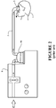
- Figure 2 shows a schematic view of the user 1 receiving heated and humidified air from an integrated respiratory assistance system 6. The system operates in the same manner as the modular system shown in Figure 1 , except the humidification chamber 4b has been integrated with the blower unit to form the integrated system 6.
- the user interface 5 shown in Figures 1 and 2 is a nasal mask, covering the nose of the user 1.
- a mask that covers the mouth and nose, a full face mask, a nasal cannula, or any other suitable user interface could be substituted for the nasal mask shown.
- a mouth-only interface or oral mask could also be used.
- the patient or user end of the conduit can be connected to a tracheostomy fitting, or an endotracheal intubation.
- US 7,111,624 includes a detailed description of an integrated system.
- a 'slide-on' water chamber is connected to a blower unit in use.
- a variation of this design is a slide-on or clip-on design where the chamber is enclosed inside a portion of the integrated unit in use.
- An example of this type of design is shown in WO 2004/112873 , which describes a blower, or flow generator 50, and an associated humidifier 150.
- the most common mode of operation is as follows: air is drawn by the blower through an inlet into the casing which surrounds and encloses at least the blower portion of the system.
- the blower pressurises the air stream from the flow generator outlet and passes this into the humidifier chamber.
- the air stream is heated and humidified in the humidifier chamber, and exits the humidifier chamber via an outlet.
- a flexible hose or conduit is connected either directly or indirectly to the humidifier outlet, and the heated, humidified gases are passed to a user via the conduit. This is shown schematically in Figure 2 .
- the gases provided by the blower unit are generally sourced from the surrounding atmosphere.
- some forms of these systems may be configured to allow a supplementary gas to be blended with the atmospheric air for particular therapies.
- a gases conduit supplying the supplemental gas is typically either connected directly to the humidifier chamber or elsewhere on the high pressure (flow outlet) side of the blower unit, or alternatively to the inlet side of the blower unit as described in WO 2007/004898 .
- This type of respiratory assistance system is generally used where a patient or user requires oxygen therapy, with the oxygen being supplied from a central gases source. The oxygen from the gases source is blended with the atmospheric air to increase the oxygen fraction before delivery to the patient.
- Such systems enable oxygen therapy to be combined with high flow humidification therapy for the treatment of diseases such as COPD.
- the blower unit typically comprises a fan or impeller that is rotatably driven by a variable speed motor and the respiratory assistance system typically further comprises an electronic controller that is configured to control the motor speed of the blower unit to generate a desired flow rate, for example in high flow humidification therapy, based on input from a user input interface.
- Correct operation of the respiratory assistance system requires an intact flow path from gases inlet of the system to the user interface. Typically, manual observation of the connected components in the flow path is used to determine if any such flow path faults exist and require remedy.
- WO 2006/133494 describes a method of operating a device for treating sleep disordered breathing.
- One disclosed method seeks to apply the lowest pressure required to treat the patient effectively and limits maximum pressure in circumstances of mask leak.
- EP 0661071 describes an apparatus and method for the automated stop-start control in the administration of continuous positive airway pressure (CPAP) treatment.
- the starting of the administration of CPAP treatment occurs when it is determined that the patient is wearing the mask.
- the ceasing of the administration of CPAP treatment is done when it is determined that the patient is no longer wearing the mask.
- US 2009/0199850 describes a ventilation device for non-invasive positive pressure ventilation (NIPPV) or continuous positive airway pressure (CPAP) treatment of a patient.
- the device includes one or more relationships stored in data storage of the controller relating combinations of parameter values as being indicative of fault conditions of the device operation, the sensors and/or the fault detection process.
- the invention comprises a method for detecting a fault in the flow path of a respiratory assistance apparatus, the flow path comprising a motor-driven blower unit that is configured to generate a flow of gases and which is connected to a humidification unit that is configured to heat and humidify the flow of gases, comprising:
- the first motor speed is within a first predetermined motor speed range and the second motor speed is within a predetermined second motor speed range.
- the first motor speed range comprises the motor speeds required to generate a sensed flow rate in the flow path of below 25 L/min and the second motor speed range comprises the motor speeds required to generate a sensed flow rate in the flow path of at or above 25 L/min.
- the first motor speed is below 6500 rpm.
- the higher second motor speed is at or above 6500 rpm.
- the higher second motor speed is at least 6000 rpm when the respiratory apparatus is operating in an adult mode and delivering the flow of gases to a user via an adult cannula. In some embodiments, the higher second motor speed is at least 4000 rpm when the respiratory apparatus is operating in a junior mode and delivering the flow of gases to a user via a pediatric cannula.
- the first motor speed is the current operating motor speed of the respiratory assistance apparatus. In other embodiments, the method further comprises changing the current operating motor speed to the first motor speed prior to sensing the flow rate.
- the humidification unit comprises a humidification chamber and sensing the flow rate comprises sensing the flow rate in the flow path prior to the humidification chamber.
- the flow rate is sensed in the flow path prior to the blower unit.
- the invention comprises a method for detecting a fault in the flow path of a respiratory assistance apparatus, the flow path comprising a motor-driven blower unit that is configured to generate a flow of gases and which is connected to a humidification unit that is configured to heat and humidify the flow of gases, comprising:
- the first set flow rate is within a first predetermined flow rate range and the second set flow rate is within a predetermined second flow rate range.
- the first set flow rate range comprises flow rates below 25 L/min and wherein the second set flow rate range comprises flow rates at or above 25 L/min.
- the first set flow rate is the current operating flow of the respiratory assistance apparatus. In other embodiments, the method further comprises changing the current set flow rate of the respiratory assistance apparatus to the first set flow rate prior to determining the motor speed.
- the invention comprises a method for detecting a fault in the flow path of a respiratory assistance apparatus, the flow path comprising a motor-driven blower unit that is configured to generate a flow of gases and which is connected to a humidification unit that is configured to heat and humidify the flow of gases, comprising:
- the first set flow rate is in a flow rate range below 25 L/min and wherein the higher motor speed is in a motor speed range comprising motor speeds required to generate a sensed flow rate in the flow path at or above 25 L/min.
- the higher motor speed is at or above 6500 rpm.
- the higher motor speed is at least 6000 rpm when the respiratory apparatus is operating in an adult mode and delivering the flow of gases to a user via an adult cannula. In some embodiments, the higher motor speed is at least 4000 rpm when the respiratory apparatus is operating in a junior mode and delivering the flow of gases to a user via a pediatric cannula.
- the first set flow rate is the current operating flow of the respiratory assistance apparatus. In other embodiments, the method further comprises changing the current set flow rate of the respiratory assistance apparatus to the first set flow rate prior to determining the motor speed.
- the humidification unit comprises a humidification chamber and sensing the flow rate comprises sensing the flow rate in the flow path prior to the humidification chamber.
- the flow rate is sensed in the flow path prior to the blower unit.
- the invention comprises a method for detecting a fault in the flow path of a respiratory assistance apparatus, the flow path comprising a motor-driven blower unit that is configured to generate a flow of gases and which is connected to a humidification unit that is configured to heat and humidify the flow of gases, comprising:
- the first motor speed is in a motor speed range comprising motor speeds required to generate a sensed flow rate in the flow path of below 25 L/min and wherein the higher set flow rate comprises flow rates at or above 25 L/min.
- the first motor speed is the current operating motor speed of the respiratory assistance apparatus. In other embodiments, the method further comprises changing the current operating motor speed to the first motor speed prior to sensing the flow rate.
- the humidification unit comprises a humidification chamber and sensing the flow rate comprises sensing the flow rate in the flow path prior to the humidification chamber.
- the flow rate is sensed in the flow path prior to the blower unit.
- the first threshold has a higher probability of false alarm compared to the second threshold.
- the first and second thresholds are discrete stored values.
- the first and second thresholds are extracted from respective stored threshold lines representing the flow rate threshold against motor speed for a predetermined motor speed range, and/or stored threshold lines representing the motor speed threshold against set flow rates for a predetermined flow rate range.
- the first and second thresholds are configured for detecting a leak in the flow path such that the fault detection signal is indicative of detected leak in the flow path.
- the method further comprises adjusting the first threshold by a predetermined level if the fault detection signal is not generated.
- adjusting the first threshold comprises limiting the first threshold to a limit level.
- the method further comprises triggering an alarm if the fault detection signal is generated.
- the invention comprises a method for detecting a fault in the flow path of a respiratory assistance apparatus, the flow path comprising a motor-driven blower unit that is configured to generate a flow of gases and which is connected to a humidification unit that is configured to heat and humidify the flow of gases, comprising:
- the first and second thresholds are configured for detecting a blockage in the flow path such that the fault detection signal is indicative of a detected blockage in the flow path.
- the higher second motor speed is at least 2000 rpm when the respiratory apparatus is operating in an adult mode and delivering the flow of gases to a user via an adult cannula. In some embodiments, the higher second motor speed is at least 6600 rpm when the respiratory apparatus is operating in a junior mode and delivering the flow of gases to a user via a pediatric cannula.
- the invention comprises respiratory assistance apparatus configured to provide a heated and humidified flow of gases, comprising: a gases inlet configured to receive a supply of gases; a motor-driven blower unit configured to generate a pressurized gases stream from the supply of gases; a humidification unit configured to heat and humidify the pressurized gases stream; a gases outlet for the heated and humidified gases stream; a flow path for the gases stream through the respiratory device from the gas inlet through the blower unit and humidification unit to the gases outlet; a flow rate sensor in the flow path that is configured to sense the flow rate and generate an indicative flow rate signal and/or a motor speed sensor that is configured to sense the motor speed of the blower unit and generate an indicative motor speed signal; and a control system that is configured to detect a fault in the flow path by carrying out the method as defined in any of the aspects of the invention above.
- the seventh aspect of the invention may have any one or more of the features mentioned in respect of the first-sixth aspects of the invention.
- the stream of gases may be atmospheric air or a mixture of atmospheric air augmented with a supplementary gas, such as oxygen or any other gases composition.
- Embodiments of the flow path fault detection method may be configured to detect or sense a breakage, leak, and/or blockage along the gases stream flow path, and generate an indicative fault or warning signal to the control system and/or use to remedy the fault.
- Various examples of the fault detection method will be described.
- the fault detection method is configured to detect a disconnected or removed component from the flow path, such as the removal of the humidification chamber from the flow path. If removal is detected, the fault detection method triggers an indicative warning that the humidification chamber has been removed from the humidification compartment or unit, or otherwise disconnected from the flow path.
- the fault detection method could additionally or alternatively be modified to detect the connection status (ie presence or absence) of other components in the flow path, such as the user interface (e.g. nasal cannula) of the patient interface, flexible conduit of the patient interface, and any inlet filter provided on the gases inlet of the respiratory assistance apparatus.
- the fault detection method may also be modified to identify or sense the type of components connected in the flow path, from a set of predetermined types. For example, the fault detection method could be modified to determine the type of nasal cannula installed, such as adult cannula (large, medium, small) or junior/paediatric cannula.
- the fault detection method is configured to detect any leaks in the gases stream flow path extending from the outlet of the blower unit to the user interface at the patient.
- the leaks may vary in magnitude from small to large, and may be caused by removal of components from the flow path, such as the chamber or the user interface, faulty connections between components in the flow path, perforations or holes in the flexible conduit, or any other circumstance which may cause an unacceptable leak.
- the fault detection method is configured to detect blockages in the gases flow path extending from the outlet of the blower unit to the user interface at the patient.
- the fault detection method is configured to detect both leaks and blockages in the gases flow path extending from the outlet of the blower unit to the user interface at the patient.
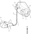
- the respiratory assistance apparatus 12 comprises a blower unit (not visible) that generates a stream of pressurised or high-flow gases which are then heated and humidified by a humidification unit in a manner described previously in the background.
- the blower unit is situated within the main housing of the respiratory apparatus 12 and receives a supply of gases from a gases inlet located in the rear of the housing (not visible).
- the outlet of the blower unit is fluidly coupled by conduits or connectors to the humidification unit.
- the humidification unit comprises a humidification chamber 14 that contains a volume of water.
- the humidification chamber 14 may be formed from a plastic or other suitable material that may have a highly heat conductive base (for example an aluminium or metal base), that is in direct contact with a heater plate 16 situated beneath the humidification chamber, and which is configured to heat the water within the humidification chamber.
- the humidification chamber has an inlet or inlet port 18 that is fluidly connected or coupled to the outlet of the blower unit.
- the humidification chamber also comprises an outlet or outlet port 20 that is fluidly connected or coupled to the gases outlet 22 of the respiratory apparatus 12.
- the high flow gases stream generated at the gases outlet 22 is delivered to a user 24 by a patient interface.
- the patient interface comprises a flexible conduit or tube 26 that is connected at one end to the gases outlet 22 of the respiratory apparatus 12 and at the other end to a user interface in the form of a nasal cannula 28.
- the user conduit 26 may be heated by an integrated heating wire or element 27.
- any other suitable user interface could be used, including, but not limited to, a mask that covers the mouth and nose, a nasal mask covering the nose, a full face mask, a mouth-only interface or oral mask, or the end of the conduit can be connected to a tracheotomy fitting, or an endotracheal intubation.
- the flow path of the gases stream in the respiratory system comprising the respiratory apparatus 12 and patient interface 26, 28, can be considered as starting at the gases inlet of the respiratory apparatus 12 and flowing through the components of the system, including the blower unit, humidification chamber 14 of the humidification unit, user conduit 26, and terminating at the outlet(s) of the user interface 28.
- the respiratory apparatus 12 comprises an electronic main controller or control system, which is configured to control the system, including the blower unit, humidification unit, and any user interface heating element in response to user settings which are input via an operable user input interface indicated at 30, which may comprise buttons, dials, touch screen input or any other type of electronic user interface.
- the user may control the flow rate, temperature and humidity of the gases stream delivered to the user 24 via input settings at the user input interface 30.
- the blower unit or flow generator comprises a motor-driven rotatable impeller or fan that is configured to draw in gases from the gases inlet and generate a pressurised gases stream or flow of gases in the flow path.
- the motor of the blower unit is a variable speed motor that is controlled by the control system or a motor speed controller via a motor speed control signal or signals to generate the desired flow rate of gases to the user.
- Various sensors may be provided along the flow path for sensing various characteristics or parameters of the gases stream, including, but not limited to, temperature sensor(s), humidity level sensor(s), and flow rate sensor(s).
- the control system receives the signals indicative of the sensed characteristics by the sensors and operates the various components accordingly to deliver the desired type of gases stream to the end user.
- the respiratory apparatus 12 at least comprises a flow rate sensor.
- the flow rate sensor is located in the flow path between the gases inlet and the blower unit and generates a flow rate signal indicative of the sensed or measured flow rate, and the flow rate signal is sent to the control system.
- the control system may use the flow rate signal for closed-loop feedback control of the blower unit motor speed to deliver a user set flow rate. For example, the motor speed is varied to minimise the error or difference between the sensed flow rate and user set flow rate, as will be appreciated.
- the flow rate sensor may, for example, be in the form of a hot-wire anemometer (HWA) flow detector, but any other suitable flow rate sensor or flow probe could be used.
- HWA hot-wire anemometer
- the flow rate sensor need not be located in the flow path prior to the blower unit but could be located anywhere in the flow path prior to the humidification chamber.
- the control system comprises a programmable controller, such as a microprocessor, microcontroller or digital signal processor, and has associated memory.
- the programmable controller may execute software commands stored in the associated memory.
- the control system receives input from sources such as the user input interface 30 and any sensors, and controls the system components such as the motor speed of the blower unit, energy level of the heater plate 16 in the humidification unit, and conduit heater wire 27 to deliver the flow of gases at the desired humidity and/or temperature and/or flow rate set by the user.
- the fault detection method is configured to detect if the humidification chamber is removed or disconnected, either completely or partially, from the flow path.
- the flow rate delivered by the respiratory apparatus is primarily determined by the motor speed of the blower unit and the air flow resistance in the flow path downstream of the blower unit. If there are significant leaks, breakages or disconnected components in the gases flow path, this will alter the air flow resistance in the flow path and therefore the flow rate generated for a particular motor speed. Such faults in the expected flow path may alter the correct operation of the control system and its ability to deliver the desired flow rate to the user. Therefore it is desirable for the control system to automatically detect such faults and warn the user.
- the humidification chamber 14 is removable from the humidification unit for cleaning and/or refilling or replacement, as will be appreciated.
- the humidification chamber represents a significant air flow resistance component in the flow path after the blower unit. Removal or dislodgement of the humidification chamber from the respiratory apparatus 12 causes a higher flow rate to be generated by the blower unit for a given motor speed, than if the humidification chamber was installed (connected in the flow path in normal operation).
- control system implementing the fault detection method is configured to automatically determine whether the humidification chamber is removed or disconnected, either entirely or partially, from the flow path and then responds accordingly by, for example, triggering a user alarm (audible and/or visual) and/or halting operation of the unit or shutting down the unit or placing it in standby mode.
- a user alarm audible and/or visual
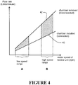
- Figure 4 shows schematically a typical flow rate versus motor speed characteristic line 40 for when a chamber is installed and a characteristic line 42 representing the flow rate versus motor speed when the chamber is removed. Based on flow rate sensed in the flow path between the blower unit and the humidification chamber. As shown, the difference between the lines 40,42 increases with speed. Therefore, it is easier to determine definitively (or with a lower false alarm rate) based on a sensed flow rate reading at a higher motor speed range as to whether the chamber is removed or installed, e.g. in region B, than at a lower speed range, e.g. in region A where the difference between the flow rates is smaller and therefore carries a higher probability of false alarms.
- the flow path fault detection method is configured to detect the humidification chamber connection status (i.e. installed/connected or removed/disconnected) based on the sensed flow rate and motor speed of the blower unit using a two-stage sensing approach of flow rate at two different motor speeds.
- the fault detection algorithm may be executed by the control system either continuously, or periodically at preset time intervals or during particular system operations or in particular modes, e.g. upon start up, or at any other suitable time.
- the control system receives a sensed flow rate signal from the flow rate sensor located between the blower unit and the humidification chamber and a motor speed signal indicative of the motor speed of the blower unit is either received from a motor speed sensor or otherwise derived by the control system.
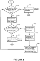
- the fault detection method starts with step 50 which comprises determining if the sensed flow rate is above a first threshold at a first motor speed.
- the fault detection algorithm is run continuously or periodically by the control system in that step 50 is initiated or performed periodically at a predetermined sample rate of the flow rate sensor signal or for every new sensed flow rate sample.
- the sensed flow rate is based on the flow rate signal generated by the flow rate sensor.
- the first threshold is a predetermined flow rate threshold that is stored in memory for the first motor speed.
- the first motor speed may be the current operating motor speed of the device in normal operation.
- the fault detection algorithm may increase or decrease the current motor speed to a predetermined stored first motor speed within a predetermined first motor speed range 106 upon initiation of the algorithm.
- the algorithm reverts to normal operation at step 52 and ends, ready for initiating at step 50 again for the next sensed flow rate sample. If the first threshold is exceeded, the fault detection algorithm then increases the motor speed of the blower unit to a second motor speed as shown at step 54.
- the second motor speed may be within a predetermined stored second motor speed range that is above the first motor speed range 106.
- the decision to move to step 54 may be based on a single flow rate sample that exceeds the first threshold. In an alternative form, the decision to move to step 54 may require a predetermined number of multiple successive flow rate samples to exceed the first threshold, to reduce the likelihood of a false alarm triggering.
- the fault detection algorithm determines whether the sensed flow rate is above a second threshold representing a predetermined stored flow rate threshold for the second motor speed.
- the algorithm If the second threshold is exceeded (as determined based on a single flow rate sample or multiple successive flow rate samples as above), then the algorithm generates a warning signal or fault detection signal 58 indicating that the humidification chamber is disconnected or removed and then the algorithm ends.
- the control system may respond to the warning signal by triggering an audible or visual alarm or modifying operation of the respiratory apparatus, for example shutting down the blower unit or otherwise entering a standby mode.
- the motor speed is decreased back to the first motor speed at 60.
- the first threshold is then increased or incremented by a predetermined level or quantity at 62.
- the modified first threshold is then compared with a first threshold upper limit.
- the modified first threshold must not exceed a predetermined stored upper limit level and if it does the modified first threshold is fixed at the upper limit threshold.
- the modified first threshold is stored and then used for future loops of the algorithm, unless it is modified again by a subsequent or future loop of the algorithm.
- any modifications to the first threshold are reset after any warning signal is generated by a subsequent loop. This means the algorithm is reset to its initial values ready for operation again once the fault has been remedied.
- step 64 the fault detection method loops back to step 50 and checks the sensed flow rate against the modified first threshold and repeats the steps above one or more times, until terminating at one of the exit points or ends.
- the thresholds may be discrete thresholds at predetermined motor speeds, or alternatively threshold lines or curves defining multiple or continuous flow rate thresholds over a range of motor speeds may be stored.
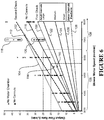
- Such threshold lines may be in the form of straight lines representing flow rate threshold versus motor speed characteristics having an offset and gradient as shown in Figure 6 .
- the threshold lines may be any other curved or arbitrary profile defined by formula or plotted between discrete points.
- Figure 6 shows an average flow rate versus motor speed characteristic line 116 for when the humidification chamber is connected in the flow path, but where there is no cannula 116 connected to the end of the flexible conduit 26 of the patient interface, generated by experimental operation of a respiratory assistance apparatus of the type shown in Figure 3 .
- various motor speeds e.g. 3000 rpm, 3500 rpm, 4000 rpm, 5000 rpm, 6000 rpm, 7000 rpm, 8000 rpm
- the flow rate was sampled for when the gases flow path comprises a connected humidification chamber and no cannula.
- the set of flow rate samples for a motor speed of 7000 rpm is shown at 120.
- the other flow rate samples at the other speeds are represented by the sample graph symbols.
- the flow rate was sampled for the same gases flow path, but with the humidification chamber removed/disconnected and these samples are plotted on the graph by the symbols indicated at 118.
- the flow rate samples 118,120 overlap considerably at the lower speeds, making it difficult to determine a flow rate that indicates the chamber has been disconnected, as was explained with reference to Figure 4 .
- the overlap between the sets of samples 118,120 reduces and they become sufficiently distinct from one another such that it is easier to determine a flow rate that represents when the chamber has been removed.
- the first threshold line 100 is situated below the second threshold line 102.
- the purpose of this is that the first threshold line represents a conservative (high sensitivity) threshold in the first-stage of sensing for detecting whether the sensed flow rate is indicative of chamber disconnection or removal for motor speeds in the a first speed range 106.
- the first speed range typically covers the range of motor speeds where there is some overlap between the flow rate samples 118,120. For the experimental respiratory assistance apparatus used for generating Figure 6 , there is no overlap and sufficient displacement between the flow rate samples at approximately 6500 rpm, or when the flow rate is about 25 L/min.
- the first speed range for sensing the flow rate against the first threshold is therefore defined at any motor speed in the motor speed range required to generate a flow rate below approximately 25 L/min in the gases flow path, which for the experimental apparatus for a gases flow path with no cannula is a motor speed below 6500 rpm.
- the second speed range for sensing the flow rate is defined as any motor speed in the motor speed range required to generate a flow rate at or above 25 L/min in the gases flow path, which for the experimental apparatus for a gases flow path with no cannula is a motor speed at or above approximately 6500 rpm.
- the first speed range is the motor speed range required to generate a flow rate of at or below approximately 20 L/min (motor speeds at or below approximately 5700 rpm in the experimental apparatus for a gases flow path with chamber but no cannula) and the second speed range is the motor speed range required to generate a flow rate at or above 25 L/min (motor speeds at or above approximately 6500 rpm in the experimental apparatus for a gases flow path with chamber but no cannula).
- the first and second speed ranges are defined relative to flow rate generated rather than absolute speed values because the respiratory apparatus may comprise motors having different power and speed characteristics, and because the gases flow path may or may not comprise a connected cannula, and any connected cannula may have a varied size and therefore air flow resistance component.
- the first threshold line 100 is conservative in that the flow rate threshold versus motor speed profile characteristic may be generated based on the characteristic profile of the flow rate versus motor speed should the flow path air resistance be reduced by a level smaller than that of removing the humidification chamber.
- the first threshold line may be set based on the expected flow rate versus motor speed characteristic for a flow path in which the nasal cannula or user conduit has been removed from the flow path.
- the first threshold line 100 is a line extending below the flow rate versus motor speed characteristic line 116 for the gases flow path comprising the chamber but no cannula.
- the first threshold line extends between line 116 and line 122 representing the flow rate versus motor speed characteristic for a gases flow path comprising the chamber and a large adult cannula connected.
- the first threshold therefore does not definitively indicate that the humidification chamber has been disconnected or removed from the gases flow path, but signals that there may be some modification (reduction) to the gases flow path resistance and therefore some possible fault.
- the first threshold has an associated probability of false alarm that is higher than that associated with the second threshold.
- the second threshold line 102 is based on the true or expected flow rate versus motor speed characteristic with the humidification chamber removed from the gases flow path.
- the second threshold line 102 represents the second threshold at the second higher motor speed range 108 which the sensed flow rate is compared to in the second-stage of sensing in the fault detection method. As shown, the second threshold line is above or exceeds the first threshold line along the motor speed range axis.
- the fault detection method may operate with a first motor speed of 5500 rpm, which corresponds to a first flow rate threshold of approximate 15 L/min as indicated at 110. If the sensed flow rate at 5500 rpm does not exceed 15 L/min, then no warning signal is generated and the respiratory apparatus operates as normal. If the sensed flow rate exceeds 15 L/min, then the motor speed of the blower unit is increased or ramped to a second higher motor speed such as approximately 7100 rpm, in which case the second flow rate threshold applies corresponding to approximately 36 L/min as indicated at 112.
- the algorithm reduces the motor speed back to 5500 rpm and increases the first threshold 110 by a predetermined level, e.g., to say 16 L/min as indicated at 114, toward an upper limit line 104.
- the sensed flow rate is then compared against the modified first threshold 114 and repeats the algorithm from step 50 one or more times as previously indicated until terminating at one of the exit points.
- the purpose of modifying the first threshold is to prevent the algorithm from oscillating back and forward between first and second threshold sensing stages in an endless loop. As mentioned, the first threshold will not be increased beyond the predetermined upper limit line 104. If only a single discrete first motor speed is employed by the fault detection method, then the first threshold at that motor speed need only be modified (increased). However, if the fault detection method assesses the sensed flow rate against any arbitrary motor speed in the first motor speed range (thereby requiring a first threshold line representing the flow rate threshold over a range of motor speeds), the modification of first threshold may require modification of the entire first threshold line, e.g., increasing the gradient and/or offset.
- the fault detection method above is based on comparing the sensed flow rate against two different thresholds, at two different motor speeds.
- the purpose of the dual speed or two-stage sensing approach of fault detection is to reduce or minimize the chances of false alarms, e.g., a warning signal being generated incorrectly when the chamber is installed correctly.
- the first motor speed is typically in a first motor speed range that is in the normal operating speed range for generating typical flow rates for high flow therapy.
- the difference between the sensed flow rate when the chamber is installed and removed is small, and it is difficult to discriminate between the two, making the threshold level difficult to set without either creating a high probability of false alarms (sensitivity too high), or alternatively, not adequately detecting legitimate faults (sensitivity too low).
- the two-stage or multi-stage sensing approach addresses this issue.
- the first threshold in the first speed range is set at a conservative level having an associated higher probability of false alarms for indicating chamber disconnection/removal relative to the second threshold.
- false alarms are filtered out by the second threshold detection stage, in which the motor speed is increased to the second higher motor speed range where the difference between the flow rate versus motor speed characteristic between when the chamber is installed and when it is removed, is more prominent (easier to discriminate as shown and explained previously with reference to Figure 4 ), and the sensed flow rate is then compared to a second threshold at this higher, second motor speed.
- the second threshold is set to a value having a lower probability of false alarms compared with the first threshold at the lower first speed range.
- the fault detection method described herein also alters the first threshold dynamically such that it calibrates the first threshold for the particular respiratory apparatus configuration, and thus, increases detection efficacy.
- the first threshold line is progressively modified or fine tuned during operation of the algorithm to a value having a reduced probability of false alarms relative to its original value.
- the methods or algorithms as described above may be implemented in hardware, software, firmware, middleware, microcode, or any combination of these.
- the methods or algorithms may be embodied directly in hardware, in a software module executable by a processor, or a combination of these, and may be in the form of a processing unit or programmable instructions, and may be contained in a single device or distributed across multiple devices.
- the software module may reside in any form of memory, including RAM memory, flash memory, ROM memory, EPROM memory, EEPROM memory, registers, hard disc, removable disc, CD-ROM or any other form of storage medium.
- a storage medium or memory may be coupled to the processor such that the processor can read information from, and write information to, the storage medium. In an alternative embodiment/form, the storage medium may be integral to the processor.
- the methods may also be provided in a computer-readable medium having stored thereon computer executable instructions that, when executed on a processing device, cause the processing device to perform the method or methods.
- control system of the respiratory assistance apparatus 12 typically at least comprises a programmable processor 150 and associated memory 152.
- the method or algorithm is implemented in software defined by programmable instructions that are stored in memory 152 and implemented by the processor 150 to carry out the algorithm steps described above with reference to Figure 5 .
- the various flow rate thresholds and motor speeds are stored in memory and retrieved by the processor during operation.
- control system receives a flow rate signal 154 from the flow rate sensor 156 that is situated in the flow path between the blower unit and humidification chamber and which generates the flow rate signal which is indicative of the flow rate in the flow path.
- the control system also communicates with the motor 158 of the blower unit.
- control system sends control signals (160) to the blower unit motor to control the motor speed during operation of the respiratory apparatus, and a motor speed sensor 162 may also be provided which generates a motor speed signal 164 indicative of the motor speed.
- An alarm 166 which may be audible and/or visual, e.g., displayed on the user input interface, may be provided for alerting the user to a fault detection, e.g., when the chamber is removed or disconnected during use.
- the control signal system may trigger the alarm 166 by an alarm control signal 168.
- the flow rate of the gases in the gases flow path is largely proportional to the motor speed for a given respiratory assistance apparatus configuration.
- the fault detection algorithm controls the motor speed and at each of the two stages of sensing compares the flow rate sensed to flow rate thresholds at two different motor speeds based on the principle that an increased generated flow rate at any particular motor speed represents a loss in air flow resistance in the gases flow path.
- the fault detection algorithm may be modified such that it controls the flow rate generated, and at each of the two stages of sensing, compares the motor speed required to generate the set flow rate against motor speed thresholds at each different flow rate, based on the principle that a reduced motor speed required to generate a set flow rate, represents a loss in the gases flow path resistance.
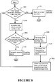
- Figure 8 shows a second embodiment of the fault detection method which is implemented in this way.
- the operation of the second embodiment fault detection method is similar to the first, except that the set flow rate is controlled and the motor speed is sensed or determined and compared against thresholds.
- the primary differences will be explained below, but all other aspects are substantially the same.
- the sensed motor speed is compared against a first motor speed threshold at a first set flow rate.
- the first set flow rate may be the current operating flow rate or the control system may control the motor speed to generate the first set flow rate. If the motor speed is above the first threshold, then the algorithm exits at 52. If the motor speed is below the first threshold, then the flow rate is increased to a higher second set flow rate at 54A.
- the sensed motor speed required to generate the higher second set flow rate is then compared against a second threshold motor speed. If the sensed motor speed falls below the second threshold motor speed, then a warning signal is generated at 58 indicating that the chamber has been removed or disconnected or at least partially dislodged from the gases flow path.
- the set flow rate is reduced to the first set flow rate at 60A, and the first motor speed threshold is reduced by a predetermined level.
- the first threshold is not allowed to go below a first threshold lower limit, and is fixed at that lower limit if it does.
- the algorithm then loops back to the start step 50A and recompares the motor speed with the modified first threshold and repeats the algorithm steps until exiting.
- the first set flow rate is in the range of below 25 L/min, and the second set flow rate is in the range of at or above 25 L/min. In one preferred embodiment, the first set flow rate is at or below 20 L/min, and the second set flow rate is at or above 25 L/min.
- steps 50, 60, 62, and 64 in Figure 5 may be replaced by steps 50A, 60A, 62A, and 64A of Figure 8 respectively.
- steps 50A, 60A, 62A, 64A in Figure 8 may be replaced with steps 50, 60, 62, and 64 of Figure 5 respectively.
- the fault detection algorithm in the first example was configured to detect the disconnection, removal or dislodgement, whether partial or complete, of the humidification chamber from the gases flow path and to generate an indicative warning signal for the control system to take a fault action, such as halt the system operation and/or trigger an alarm to the user or similar.
- This sort of disruption to the gases flow path or breathing circuit can be considered as one type of leak.
- leaks in the gases flow path may also be caused by other circumstances, including, but not limited to, removal of the user interface such as the cannula from the conduit, a faulty or unsealed connection between the conduit and outlet of the housing in the respiratory apparatus, a faulty or unsealed connection between the cannula and the end of the conduit, a hole or perforation in the wall of the conduit, or any other circumstances causing a leak in the gases flow path.
- the thresholds in the fault detection method described in the first example can be modified to be more sensitive such that they detect any unacceptable leak ranging in magnitude from complete removal of the chamber as in the first example to a more minor leak caused by a faulty connection or perforation in the conduit.
- the flow charts described with reference to Figures 5 and 8 and the other variants described are equally applicable for a fault detection method configured to detect all such leaks.
- the fault detection method for leaks may be configured to operate in different modes, suitable to different flow path configurations.
- the fault detection system method may operate in a first mode for a first type of cannula (e.g. adult mode for an adult cannula), and a second mode for a second type of cannula (e.g. junior mode for a pediatric cannula).
- the thresholds and associated motor speed ranges and/or set flow rate ranges may be varied to suit the specific flow path configuration characteristics such as the expected normal air flow path resistance of the different configurations.
- the apparatus is operating in adult mode with an adult cannula at the end of the conduit.
- the fault detection method is configured to ramp the motor to a second motor speed (e.g. step 54 in Figure 5 ) that is at least (i.e. equal to or above) 6000 rpm for re-sensing the flow rate against the second threshold (e.g. step 56 in Figure 5 ).
- the fault detection method is configured to ramp to a second motor speed that is at least 4000 rpm for re-sensing of the flow rate against the second threshold.
- the fault detection method may be configured to detect blockages in the gases flow path as will be explained in this third example with reference to Figure 9 .
- the leak detection it has been discovered that it is generally more difficult to distinguish between acceptable flow rate values and overly low flow values, which could indicate a blockage, when the respiratory assistance apparatus is set to operate at low motor speeds or flow rates. It has been discovered that it is easier to distinguish between normal or acceptable flow rates and flow rates that are indicative of a blockage in the gases flow path at higher motor speeds and/or flow rates.
- the fault detection method can be configured to detect blockages in a similar but modified approach to the previous examples.
- the fault detection method for blockages starts with step 200 which comprises determining if the sensed flow rate is below a first threshold at a first motor speed.
- the fault detection algorithm may be run continuously or periodically by the control system in that step 200 is initiated or performed periodically at a predetermined sample rate of the flow rate sensor signal or for every new sensed flow rate sample.
- the first threshold is a predetermined flow rate threshold that is stored in memory for the first motor speed.
- the first motor speed may be the current operating motor speed of the device in normal operation.
- the first threshold for that motor speed may be extracted or determined from a first threshold line that extends across a first motor speed range. If the sensed flow rate is above the first threshold, the algorithm reverts to normal operation at step 202 and ends, ready for initiating at step 200 again for the next sensed flow rate sample. This means that no blockage has been detected.
- the fault detection algorithm then increases the motor speed of the blower unit to a second higher motor speed as shown at step 204.
- the second motor speed may be within a predetermined stored second motor speed range that is above the first motor speed range.
- the fault detection algorithm determines whether the sensed flow rate is below a second threshold representing a predetermined stored flow rate threshold for the second motor speed as shown at step 206. If the sensed flow rate is below the second threshold, the algorithm generates a warning signal or fault detection signal as shown at 208 indicating that a blockage has been detected.
- the control system may then respond accordingly to the warning signal by triggering an audible or visual alarm or modifying operation of a respiratory apparatus, for example shutting down the blower unit or otherwise entering a standby mode.
- the motor speed is decreased back to the first motor speed as shown at step 210.
- the first threshold is then decreased by a predetermined level or quantity as shown at step 212.
- the modified first threshold is then compared with a first threshold lower limit.
- the modified first threshold must not go below this predetermined stored lower limit level and if it does the modified first threshold is fixed at the lower limit threshold level as shown at 214.
- the modified first threshold is then stored and used for future loops of the algorithm, unless it is modified again by a subsequent or future loop of the algorithm. Any modifications to the first threshold can be reset after a warning signal is generated by a subsequent loop so that the algorithm is reset to its initial values ready for operation once the fault has been remedied.
- step 214 the fault detection method loops back to the start 200 and checks the sensed flow rate against the modified first threshold and repeats the steps above one or more times, until terminating at one of the exit points or ends.
- the first threshold is highly sensitive and is set to have a higher associated probability of false alarm relative to the second threshold, which is set based on the true or expected flow rate versus motor speed characteristic for a flow path having a blockage.
- the fault detection method for blockage detection may be configured with settings that suit different apparatus modes of operation and/or flow path configurations.
- the apparatus is operating in adult mode with an adult cannula at the end of the conduit.
- the fault detection method is configured to ramp the motor to a second motor speed (e.g. step 204 in Figure 9 ) that is at least (i.e. equal to or above) 2000 rpm for re-sensing the flow rate against the second threshold (e.g. step 206 of Figure 9 ).
- the fault detection method is configured to ramp to a second motor speed that is at least 6600 rpm for re-sensing of the flow rate against the second threshold.
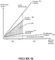
- the fault detection methods for determining leaks and blockages as described in the previous examples may be combined into a single fault detection method that is configured to detect both leaks and blockages.
- the system may operate the leak detection algorithm based on a first leak threshold 220 and a second leak threshold 222 (equivalent to the first and second thresholds described in the previous examples relating to leak detection), and the blockage detection algorithm based on a first blockage threshold 224 and a second blockage threshold 226 (equivalent to the first and second thresholds described in the previous example relating to blockage detection).
- the sensed flow rate is continuously or periodically compared against the first thresholds 220, 224 at a first lower motor speed range 228 (e.g. normal operating range) for possible leaks or blockages. If a possible leak or blockage is detected in the first motor speed range 228, the motor speed is ramped to a higher second motor speed range 230 where the sensed flow rate is compared against the relevant second threshold 222 or 226 depending on whether a possible leak or blockage was detected.
- the first threshold represents a conservative (high sensitivity) threshold and the second thresholds are based on a true or expected flow rate versus motor speed characteristic for the gases flow path which would indicate either an unacceptable leak or blockage, respectively.
- the first thresholds have an associated probability of false alarm that is higher than that associated with the corresponding second thresholds.
- the leak thresholds are above the blockage thresholds as shown.
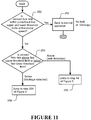
- the process starts at 250 by determining whether the sensed flow rate is within the predefined first leak and blockage thresholds 220, 224, i.e. whether the sensed flow rate is within the shaded region indicated by 232 at any first motor speed in the first motor speed range 228. If the sensed flow rate is within the normal operating region 232, defined between the upper first leak threshold and lower first blockage threshold, then the algorithm reverts back to normal operation such that no leak or blockage is detected as indicated at 252. If a sensed flow rate falls outside the normal operating region 232 in the first motor speed range 228, then a decision is made on whether a possible leak or blockage has been detected. In particular, at step 254, it is determined whether the sensed flow rate is above the first leak threshold 220 in the leak detection region or below the first blockage threshold 224 in the blockage detection region.
- the process moves to the leak detection process 256 which carries out the algorithm described with reference to Figure 5 , commencing at step 54.
- the process ramps the motor speed to the second motor speed range 230 and determines whether the sensed flow rate at the second higher motor speed exceeds the second leak threshold 222 such that a leak is detected and a warning signal generated, or otherwise modifies the first leak threshold and loops back to the start as previously described in relation to Figure 5 .
- the process moves to the blockage detection process 258 which carries out the algorithm described with reference to Figure 9 , commencing at step 204.
- the process ramps the motor speed to the second motor speed range 230 and determines whether the sensed flow at the second higher motor speed is below the second blockage threshold 226 such that a blockage is detected and a warning signal generated, or otherwise modifies the first blockage threshold and loops back to the start as described in relation to Figure 9 .
Landscapes
- Health & Medical Sciences (AREA)
- Pulmonology (AREA)
- Life Sciences & Earth Sciences (AREA)
- Public Health (AREA)
- Anesthesiology (AREA)
- Biomedical Technology (AREA)
- Heart & Thoracic Surgery (AREA)
- Hematology (AREA)
- Emergency Medicine (AREA)
- Animal Behavior & Ethology (AREA)
- General Health & Medical Sciences (AREA)
- Engineering & Computer Science (AREA)
- Veterinary Medicine (AREA)
- Air Conditioning Control Device (AREA)
- Respiratory Apparatuses And Protective Means (AREA)
- Air Humidification (AREA)
- Ventilation (AREA)
- Otolaryngology (AREA)
- Control Of Positive-Displacement Air Blowers (AREA)
Claims (17)
- Un procédé de détection d'un défaut dans le trajet d'écoulement d'un appareil d'assistance respiratoire (12), le trajet d'écoulement comprenant un bloc ventilateur motorisé (158) configuré pour générer un flux de gaz et connecté à un bloc humidificateur configuré pour chauffer et humidifier le flux de gaz, comprenant les étapes consistant à :capter le débit dans le trajet d'écoulement à une première vitesse du moteur du bloc ventilateur (158) ;détecter si le débit capté dépasse un premier seuil mémorisé à la première vitesse du moteur ;augmenter la vitesse du moteur du bloc ventilateur (158) jusqu'à une deuxième vitesse de moteur plus élevée si le premier seuil est dépassé ;capter à nouveau le débit dans le trajet d'écoulement à la deuxième vitesse du moteur ; etgénérer un signal de détection de défaut (58) si le débit capté à nouveau à la deuxième vitesse du moteur dépasse un deuxième seuil mémorisé.
- Un procédé de détection d'un défaut dans le trajet d'écoulement d'un appareil d'assistance respiratoire (12), le trajet d'écoulement comprenant un bloc ventilateur motorisé (158) configuré pour générer un flux de gaz et connecté à un bloc humidificateur configuré pour chauffer et humidifier le flux de gaz, comprenant les étapes consistant à :déterminer la vitesse du moteur du bloc ventilateur (158) requise pour générer un premier débit défini dans le trajet d'écoulement ;détecter si la vitesse du moteur descend au-dessous d'un premier seuil mémorisé au premier débit défini ;augmenter le débit jusqu'à un deuxième débit défini plus élevé si la vitesse du moteur descend au-dessous du premier seuil ;déterminer à nouveau la vitesse du moteur du bloc ventilateur (158) requise pour générer le deuxième débit défini dans le trajet d'écoulement ; etgénérer un signal de détection de défaut (58) si la vitesse du moteur déterminée à nouveau au deuxième débit défini descend au-dessous d'un deuxième seuil mémorisé.
- Un procédé de détection d'un défaut dans le trajet d'écoulement d'un appareil d'assistance respiratoire (12), le trajet d'écoulement comprenant un bloc ventilateur motorisé (158) configuré pour générer un flux de gaz et connecté à un bloc humidificateur configuré pour chauffer et humidifier le flux de gaz, comprenant les étapes consistant à :déterminer la vitesse du moteur du bloc ventilateur (158) requise pour générer un premier débit défini dans le trajet d'écoulement ;détecter si la vitesse du moteur descend au-dessous d'un premier seuil mémorisé au premier débit défini ;augmenter la vitesse du moteur du bloc ventilateur (158) jusqu'à une vitesse de moteur plus élevée si la vitesse du moteur définie descend au-dessous du premier seuil ;capter le débit dans le trajet d'écoulement à la vitesse de moteur plus élevée ; etgénérer un signal de détection de défaut (58) si le débit capté à la vitesse du moteur plus élevée dépasse un deuxième seuil mémorisé.
- Un procédé de détection d'un défaut dans le trajet d'écoulement d'un appareil d'assistance respiratoire (12), le trajet d'écoulement comprenant un bloc ventilateur motorisé (158) configuré pour générer un flux de gaz et connecté à un bloc humidificateur configuré pour chauffer et humidifier le flux de gaz, comprenant les étapes consistant à :capter le débit dans le trajet d'écoulement à une première vitesse du moteur du bloc ventilateur (158) ;détecter si le débit capté dépasse un premier seuil mémorisé à la première vitesse du moteur ;augmenter le débit jusqu'à un débit défini plus élevé si le débit capté dépasse le premier seuil ;déterminer la vitesse du moteur du bloc ventilateur (158) requise pour générer le débit défini plus élevé dans le trajet d'écoulement ; etgénérer un signal de détection de défaut (58) si la vitesse de moteur déterminée au débit défini plus élevé descend au-dessous d'un deuxième seuil mémorisé.
- Un procédé selon la revendication 1, la première vitesse de moteur étant à l'intérieur d'une première plage prédéterminée de vitesses de moteur et la deuxième vitesse de moteur étant à l'intérieur d'une deuxième plage prédéterminée de vitesses de moteur.
- Un procédé selon la revendication 5, la première plage de vitesses de moteur comprenant les vitesses de moteur requises pour générer un débit capté dans le trajet d'écoulement de moins de 25 L/min et la deuxième plage de vitesses de moteur comprenant les vitesses de moteur requises pour générer un débit capté dans le trajet d'écoulement de 25 L/min ou plus..
- Un procédé selon la revendication 2, le premier débit défini étant à l'intérieur d'une première plage de débits prédéterminée et le deuxième débit défini étant à l'intérieur d'une deuxième plage de débits prédéterminée.
- Un procédé selon la revendication 7, la première plage de débits définis comprenant des débits inférieurs à 25 L/min et la deuxième plage de débits définis comprenant des débits de 25 L/min ou plus.
- Un procédé selon la revendication 3, le premier débit défini se trouvant dans une plage de débits de moins de 25 L/min et la vitesse de moteur plus élevée se trouvant dans une plage de vitesses de moteur comprenant des vitesses de moteur requises pour générer un débit capté dans le trajet d'écoulement de 25 L/min ou plus.
- Un procédé selon la revendication 4, la première vitesse du moteur se trouvant dans une plage de vitesses de moteur comprenant des vitesses de moteur requises pour générer un débit capté dans le trajet d'écoulement de moins de 25 L/min et le débit défini plus élevé comprenant des débits de 25 L/min ou plus.
- Un procédé selon une quelconque des revendications précédentes, le premier seuil étant défini pour avoir une plus grande probabilité de fausse alarme que le deuxième seuil.
- Un procédé selon une quelconque des revendications précédentes, le premier et le deuxième seuil étant des valeurs discrètes mémorisées, ou le premier et le deuxième seuil étant extraits de lignes de seuil mémorisées respectives représentant le seuil de débit par rapport à une vitesse du moteur pour une plage de vitesses de moteur prédéteminée et/ou des lignes de seuil mémorisées représentant le seuil de vitesse de moteur par rapport à des débits définis pour une plage de débits prédéterminée.
- Un procédé selon la revendication 1, la première vitesse de moteur étant inférieure à 6500 tr/min, ou la deuxième vitesse de moteur ou vitesse plus élevée étant de 6500 tr/min ou plus.
- Un procédé selon une quelconque des revendications précédentes, le premier et le deuxième seuil étant configurés pour détecter le retrait d'une chambre d'humidification du bloc d'humidification dans le trajet d'écoulement de manière à ce que le signal de détection de défaut (58) indique la déconnexion ou le retrait de la chambre d'humidification du trajet d'écoulement, ou le premier et le deuxième seuil étant configurés pour détecter une fuite dans le trajet d'écoulement de manière à ce que le signal de détection de défaut (58) indique qu'une fuite a été détectée dans le trajet d'écoulement.
- Un procédé selon une quelconque des revendications précédentes, comprenant en sus l'étape consistant à ajuster le premier seuil d'un niveau prédéterminé si un signal de détection de défaut (58) n'est pas généré.
- Un procédé selon la revendication 15, l'étape consistant à ajuster le premier seuil comprenant en sus l'étape consistant à limiter le premier seuil à un niveau limite.
- Un appareil d'assistance respiratoire configuré pour fournir un flux de gaz chauffé et humidifié, comprenant :une entrée des gaz configurée pour recevoir une alimentation en gaz ;un bloc ventilateur motorisé (158) configuré pour générer un flux de gaz sous pression à partir de l'alimentation en gaz ;un bloc humidificateur configuré pour chauffer et humidifier le flux de gaz sous pression ;une sortie des gaz (22) pour le flux des gaz chauffés et humidifiés ;un trajet d'écoulement pour le flux des gaz à travers le dispositif respiratoire (12) depuis l'entrée des gaz à travers le bloc ventilateur (158) et le bloc humidificateur jusqu'à la sortie des gaz (22) ;un capteur de débit (156) dans le trajet d'écoulement, configuré pour capter le débit et générer un signal indicateur de débit (154) et/ou un capteur de vitesse du moteur (162) configuré pour capter la vitesse du moteur du bloc ventilateur (158) et générer un signal indicateur de la vitesse de moteur (164) ; etun système de commande configuré pour détecter un défaut dans le trajet d'écoulement en mettant en oeuvre le procédé selon une quelconque des revendications 1-16.
Applications Claiming Priority (2)
| Application Number | Priority Date | Filing Date | Title |
|---|---|---|---|
| US201261650680P | 2012-05-23 | 2012-05-23 | |
| PCT/NZ2013/000088 WO2013176557A1 (fr) | 2012-05-23 | 2013-05-23 | Procédé de détection de défaut de trajet d'écoulement pour un appareil d'assistance respiratoire |
Publications (3)
| Publication Number | Publication Date |
|---|---|
| EP2852425A1 EP2852425A1 (fr) | 2015-04-01 |
| EP2852425A4 EP2852425A4 (fr) | 2016-02-10 |
| EP2852425B1 true EP2852425B1 (fr) | 2017-08-09 |
Family
ID=49624146
Family Applications (1)
| Application Number | Title | Priority Date | Filing Date |
|---|---|---|---|
| EP13794447.6A Active EP2852425B1 (fr) | 2012-05-23 | 2013-05-23 | Procédé de détection de défaut de trajet d'écoulement pour un appareil d'assistance respiratoire |
Country Status (5)
| Country | Link |
|---|---|
| US (3) | US10398861B2 (fr) |
| EP (1) | EP2852425B1 (fr) |
| AU (5) | AU2013264468B2 (fr) |
| CA (1) | CA2871850A1 (fr) |
| WO (1) | WO2013176557A1 (fr) |
Cited By (2)
| Publication number | Priority date | Publication date | Assignee | Title |
|---|---|---|---|---|
| US11679224B2 (en) | 2004-08-20 | 2023-06-20 | Fisher & Paykel Healthcare Limited | Apparatus for measuring properties of gases supplied to a patient |
| US12420038B2 (en) | 2012-05-23 | 2025-09-23 | Fisher & Paykel Healthcare Limited | Flow path fault detection method for a respiratory assistance apparatus |
Families Citing this family (26)
| Publication number | Priority date | Publication date | Assignee | Title |
|---|---|---|---|---|
| EP2113274B1 (fr) | 2008-04-30 | 2016-04-27 | ResMed R&D Germany GmbH | Appareil pour l'administration contrôlée d'un gaz respiratoire aux voies respiratoires d'un utilisateur |
| AU2013232848B2 (en) | 2012-03-15 | 2018-03-22 | Fisher & Paykel Healthcare Limited | Respiratory gas humidification system |
| WO2013162386A1 (fr) | 2012-04-27 | 2013-10-31 | Fisher & Paykel Healthcare Limited | Fonctionnalités d'usabilité pour système d'humidification respiratoire |
| WO2014078840A1 (fr) * | 2012-11-19 | 2014-05-22 | The General Hospital Corporation | Système et procédé de surveillance de la réanimation ou de la mécanique respiratoire d'un patient |
| WO2015038014A1 (fr) | 2013-09-13 | 2015-03-19 | Fisher And Paykel Healthcare Limited | Système d'humidification |
| CN108514674B (zh) | 2013-09-13 | 2021-12-24 | 费雪派克医疗保健有限公司 | 用于加湿系统的连接 |
| WO2015093989A1 (fr) | 2013-12-20 | 2015-06-25 | Fisher & Paykel Healthcare Limited | Raccordements de système d'humification |
| WO2015119515A1 (fr) | 2014-02-07 | 2015-08-13 | Fisher & Paykel Healthcare Limited | Système d'humidification respiratoire |
| US11173272B2 (en) | 2014-05-02 | 2021-11-16 | Fisher & Paykel Healthcare Limited | Gas humidification arrangement |
| EP3721932B1 (fr) | 2014-05-13 | 2024-01-31 | Fisher & Paykel Healthcare Limited | Fonctionnalités d'usabilité pour système d'humidification respiratoire |
| EP4670770A3 (fr) | 2014-06-03 | 2026-01-07 | Fisher & Paykel Healthcare Limited | Chambre d'humidification pour un appareil de thérapie respiratoire |
| EP3220992B1 (fr) | 2014-11-17 | 2021-06-23 | Fisher & Paykel Healthcare Limited | Humidification de gaz respiratoires |
| WO2016209129A1 (fr) * | 2015-06-25 | 2016-12-29 | Maquet Critical Care Ab | Augmentation d'oxygène pendant la ventilation mécanique d'un patient |
| CN114569848B (zh) * | 2015-08-14 | 2026-03-24 | 瑞思迈巴黎股份有限公司 | 监测呼吸压力治疗 |
| DE102015012930A1 (de) * | 2015-10-07 | 2017-04-13 | Löwenstein Medical Technology S.A. | Vorrichtung zur Überwachung einer Diskonnektion |
| EP3515540B1 (fr) * | 2016-09-19 | 2023-03-08 | Koninklijke Philips N.V. | Systèmes permettant l'estimation du flux dans les voies respiratoires d'un patient et du flux de fuite pour une ventilation non effractive |
| GB2601711B (en) | 2016-10-11 | 2022-11-30 | Fisher & Paykel Healthcare Ltd | Method of detecting errors in the connections in a humidification system |
| EP3535001B1 (fr) * | 2016-11-01 | 2022-01-19 | Koninklijke Philips N.V. | Système d'imagerie de commande et de diagnostic dans une ventilation mécanique |
| AU2017371480B2 (en) | 2016-12-07 | 2022-11-03 | Fisher And Paykel Healthcare Limited | Sensing arrangements for medical devices |
| EP3558432B1 (fr) | 2016-12-23 | 2024-03-27 | Koninklijke Philips N.V. | Dispositif de support de pression et procédé de détermination de changements dans un circuit de patient |
| CN118286549A (zh) * | 2017-11-22 | 2024-07-05 | 费雪派克医疗保健有限公司 | 用于呼吸流治疗系统的呼吸速率监测 |
| US11559651B2 (en) * | 2018-10-31 | 2023-01-24 | Dynasthetics, Llc | Apparatus and method for oxygen delivery to a patient during manual ventilation |
| AU2020251273B2 (en) * | 2019-03-29 | 2025-11-06 | Fisher & Paykel Healthcare Limited | Systems and methods of detecting incorrect connections in a humidification system |
| US11537282B1 (en) | 2019-05-20 | 2022-12-27 | ResMed Pty Ltd | Pressure control in PAP systems |
| CN117177791A (zh) * | 2021-03-08 | 2023-12-05 | 费雪派克医疗保健有限公司 | 用于呼吸辅助系统的警报 |
| JP2024521186A (ja) * | 2021-05-25 | 2024-05-28 | フィッシャー アンド ペイケル ヘルスケア リミテッド | 呼吸フロー療法システムにおける漏れを判断するシステム及び方法 |
Family Cites Families (284)
| Publication number | Priority date | Publication date | Assignee | Title |
|---|---|---|---|---|
| US485127A (en) | 1892-10-25 | Island | ||
| US3243753A (en) | 1962-11-13 | 1966-03-29 | Kohler Fred | Resistance element |
| GB1168770A (en) | 1965-12-01 | 1969-10-29 | Texas Instruments Inc | Self-Regulating Heaters. |
| US3638926A (en) | 1967-09-27 | 1972-02-01 | Alfred W Melville | Humidification |
| CH489758A (de) | 1968-04-25 | 1970-04-30 | Badertscher Hans | Wasserverdampfer |
| US3582968A (en) | 1968-12-23 | 1971-06-01 | Texas Instruments Inc | Heaters and methods of making same |
| CH507715A (de) | 1969-07-01 | 1971-05-31 | Hirtz Hans | Vorrichtung zum Behandeln der Atmungswege mit Warmluft |
| US3766914A (en) | 1970-07-29 | 1973-10-23 | H Jacobs | High pressure resuscitating and ventilating system incorporating humidifying means for the breathing mixture |
| SU379270A1 (ru) | 1971-02-01 | 1973-04-20 | Дозатор наркотических веществ | |
| GB1294808A (en) | 1971-08-19 | 1972-11-01 | Philips Electronic Associated | Temperature-controlled gas humidifier for a medical ventilator |
| US4051205A (en) | 1972-09-13 | 1977-09-27 | Graham Cameron Grant | Apparatus for saturated gas delivery |
| US4060576A (en) | 1972-09-13 | 1977-11-29 | Graham Cameron Grant | Method and apparatus for vapor saturated gas delivery |
| GB1448474A (en) | 1972-09-13 | 1976-09-08 | Grant G C | Humidification tank assembly for a medical humidifier |
| US3823217A (en) | 1973-01-18 | 1974-07-09 | Raychem Corp | Resistivity variance reduction |
| US3914349A (en) | 1973-04-23 | 1975-10-21 | Sunbeam Corp | Portable humidifier |
| US3913379A (en) | 1973-10-18 | 1975-10-21 | Tibor Rusz | Dynamic gas analyzer |
| GB1490974A (en) | 1973-11-12 | 1977-11-09 | Fodor I | Air humidifiers |
| US3903883A (en) | 1974-04-17 | 1975-09-09 | Respiratory Care | Variable aerosol heater with automatic temperature control |
| DE2436406C2 (de) | 1974-07-29 | 1986-04-03 | Volker O. Prof. Dr.Med. 8012 Ottobrunn Lang | Vorrichtung zum Anfeuchten und Erwärmen von Gasen, vorzugsweise von Atemgasen in Respiratoren |
| US4050823A (en) | 1974-09-05 | 1977-09-27 | Dragerwerk Aktiengesellschaft | Apparatus for continuously measuring the CO2 content in breathing gases |
| US4177376A (en) | 1974-09-27 | 1979-12-04 | Raychem Corporation | Layered self-regulating heating article |
| US4110419A (en) | 1975-04-18 | 1978-08-29 | Respiratory Care, Inc. | High-volume disposable and semi-disposable cartridge humidifier with self-contained cartridge sterilizing means, and related method |
| US4013122A (en) | 1975-05-05 | 1977-03-22 | Richard William Long | Diver's gas heater |
| US4560498A (en) | 1975-08-04 | 1985-12-24 | Raychem Corporation | Positive temperature coefficient of resistance compositions |
| JPS5343943A (en) | 1976-09-30 | 1978-04-20 | Tadao Suzuki | Apparatus for heating and moistening withdrawn medium |
| US4203027A (en) | 1977-03-07 | 1980-05-13 | Fisher & Paykel Limited | Electrically heated humidifying apparatus |
| US4152379A (en) | 1977-05-26 | 1979-05-01 | Airco, Inc. | Anesthesia humidifier |
| US4162370A (en) | 1977-06-24 | 1979-07-24 | Automation Industries, Inc. | Current carrying hose assembly |
| USD253409S (en) | 1977-08-18 | 1979-11-13 | Electromation, Inc. | Electrical connector block assembly |
| GB2056611B (en) | 1979-08-16 | 1984-01-25 | Dayco Corp | Vacuum cleaner hose assembly and method of making same |
| US4172105A (en) | 1979-02-15 | 1979-10-23 | Respiratory Care, Inc. | Pediatric cartridge humidifier |
| US4543474A (en) | 1979-09-24 | 1985-09-24 | Raychem Corporation | Layered self-regulating heating article |
| US4574188A (en) | 1982-04-16 | 1986-03-04 | Raychem Corporation | Elongate electrical assemblies |
| DE3214447C2 (de) | 1982-04-20 | 1994-05-11 | Eilentropp Hew Kabel | Ungesintertes Wickelband des Polytetrafluorethylen |
| US4459473A (en) | 1982-05-21 | 1984-07-10 | Raychem Corporation | Self-regulating heaters |
| US4500480A (en) | 1982-08-23 | 1985-02-19 | Respiratory Care, Inc. | Pediatric cartridge humidifier |
| US4682010A (en) | 1983-03-07 | 1987-07-21 | Safeway Products, Inc. | In-line electric heater for an aerosol delivery system |
| DE3311811A1 (de) | 1983-03-31 | 1984-10-04 | Hirtz & Co, 5000 Köln | Vorrichtung zum behandeln der atmungswege mit warmluft |
| US4753758A (en) | 1983-05-19 | 1988-06-28 | Intertech Resources Inc. | Respiratory humidifier |
| US4532088A (en) | 1983-05-19 | 1985-07-30 | Inspiron Corporation | Heated respiratory therapy humidifier |
| FR2557318A1 (fr) | 1983-12-26 | 1985-06-28 | A2F | Dispositif electronique assurant une interface universelle entre des capteurs et un appareil de saisie et de traitement des signaux en provenance de ces capteurs |
| US4529867A (en) | 1984-02-09 | 1985-07-16 | Inspiron Corporation | Humidifier and heater |
| JPS60159931U (ja) | 1984-04-02 | 1985-10-24 | シャープ株式会社 | 加湿器 |
| US4684786A (en) | 1984-08-01 | 1987-08-04 | Navistar International Corporation | Electrically heated fuel pick-up assembly for vehicle fuel tanks |
| CA1222300A (fr) | 1984-08-21 | 1987-05-26 | Her Majesty The Queen, In Right Of Canada, As Represented By The Minister Of National Defence | Generateur aerosol utilisant un ordinateur pour controler la concentration et la taille des particules |
| US4621632A (en) | 1984-11-01 | 1986-11-11 | Bear Medical Systems, Inc. | Humidifier system |
| US4826444A (en) | 1984-11-28 | 1989-05-02 | Atlantic Vacuum Parts Corp. | Electrified vacuum cleaner hose adapter |
| US4676237A (en) | 1985-01-29 | 1987-06-30 | Boutade Worldwide Investments Nv | Inhaler device |
| GB2173274B (en) | 1985-04-04 | 1989-02-01 | Boc Group Plc | Improvements in inhalation apparatus |
| GB2173107B (en) | 1985-04-04 | 1988-06-15 | Boc Group Plc | Improvements in inhalation apparatus |
| AU581986B2 (en) | 1985-05-22 | 1989-03-09 | Fisher & Paykel Healthcare Limited | Improvements in or relating to methods of and/or apparatus for humidifying gases |
| US4639055A (en) | 1985-06-03 | 1987-01-27 | Whirlpool Corporation | Hose coupling for vacuum cleaner |
| EP0205669B1 (fr) | 1985-06-18 | 1990-04-04 | Agfa-Gevaert N.V. | Circuit de chauffage électrique |
| US4955372A (en) | 1985-07-16 | 1990-09-11 | Transpirator Technologies, Inc. | Method and apparatus for pulmonary and cardiovascular conditioning of racehorses and competition animals |
| US4722334A (en) | 1985-07-16 | 1988-02-02 | Transpirator Technologies, Inc. | Method and apparatus for pulmonary and cardiovascular conditioning of racehorses and competition animals |
| JPS6265401A (ja) | 1985-09-18 | 1987-03-24 | 安田 繁之 | 感熱電気抵抗組成物における定常発熱温度の調整方法 |
| DE3629916A1 (de) | 1986-01-21 | 1987-07-23 | Venta Gmbh | Vorrichtung zur reinigung und/oder be- und entfeuchtung von gasen, insbesondere luft |
| BE905330A (nl) | 1986-08-26 | 1986-12-16 | Anthony Jean M | Inrichting om lucht of medische gassen in een geconditioneerde toestand, inz. bevochtigd en/of verwarmd aan een patient toe te dienen. |
| DE3629353C1 (en) | 1986-08-28 | 1988-01-07 | Draegerwerk Ag | Ventilation device |
| USD313969S (en) | 1986-11-07 | 1991-01-22 | Jacques Lacroix | Electrical connector |
| US4808793A (en) | 1986-11-13 | 1989-02-28 | Everhot Corporation | Tankless electric water heater with instantaneous hot water output |
| US4787117A (en) | 1987-01-22 | 1988-11-29 | Whirlpool Corporation | Vacuum cleaner electrical connector mount |
| US4941469A (en) | 1987-11-12 | 1990-07-17 | Carmeli Adahan | Portable ventilator apparatus |
| US4807616A (en) | 1987-07-09 | 1989-02-28 | Carmeli Adahan | Portable ventilator apparatus |
| US5092326A (en) | 1987-11-19 | 1992-03-03 | Winn Bryan D | Apparatus and method for a ventilator system |
| US4921642A (en) | 1987-12-03 | 1990-05-01 | Puritan-Bennett Corporation | Humidifier module for use in a gas humidification assembly |
| US4911157A (en) | 1988-01-07 | 1990-03-27 | Pegasus Research Corporation | Self-regulating, heated nebulizer system |
| US4829998A (en) | 1988-02-25 | 1989-05-16 | Jackson Richard R | Delivering breathable gas |
| US4911357A (en) | 1988-04-11 | 1990-03-27 | Shibaura Electronics Company, Ltd. | Humidity controller utilizing absolute humidity |
| EP0356000A3 (fr) | 1988-08-26 | 1992-05-20 | The British Petroleum Company p.l.c. | Appareil respiratoire |
| NZ226784A (en) | 1988-09-29 | 1992-10-28 | Fisher & Paykel | Gas humidifier with microporous wall |
| JPH02118555U (fr) | 1989-03-14 | 1990-09-25 | ||
| US5164652A (en) | 1989-04-21 | 1992-11-17 | Motorola, Inc. | Method and apparatus for determining battery type and modifying operating characteristics |
| US5101820A (en) | 1989-11-02 | 1992-04-07 | Christopher Kent L | Apparatus for high continuous flow augmentation of ventilation and method therefor |
| CA2004930C (fr) | 1989-12-08 | 1996-04-02 | John Richard Sikora | Circuit pour respirateur et appareil d'anesthesie |
| US5148801A (en) | 1990-03-23 | 1992-09-22 | University Of Victoria | Electronic heater-humidifier for hypothermia treatment |
| US5224923A (en) | 1990-03-26 | 1993-07-06 | Air-Shields, Inc. | Infant incubator |
| BR9101157A (pt) | 1990-03-26 | 1991-11-05 | Air Shields | Umedecedor de incubadeira para recem-nascidos |
| US5031612A (en) | 1990-04-24 | 1991-07-16 | Devilbiss Health Care, Inc. | System and method for delivering warm humidified air |
| DE4020522A1 (de) | 1990-06-28 | 1992-01-09 | Fresenius Ag | Medizinisches geraetesystem |
| US5230331A (en) | 1990-07-19 | 1993-07-27 | R. J. Instruments | Hot wire anemometer adapted for insertion in a calibration socket of a pulmonary gas flow monitor |
| IT1243853B (it) | 1990-10-19 | 1994-06-28 | Hospital Hi Tec S R L | Apparecchiatura per la respirazione a pressione positiva continua alveolare. |
| DE4034611A1 (de) | 1990-10-31 | 1992-05-07 | Stiebel Eltron Gmbh & Co Kg | Elektrischer durchlauferhitzer |
| JPH0653176B2 (ja) | 1990-11-30 | 1994-07-20 | 史朗 鈴木 | 加湿器 |
| DE4102223A1 (de) | 1991-01-23 | 1992-07-30 | Peter Dr Sc Techn Schaller | Patientenschlauch-heizung eines beatmungsgeraetes |
| GB9109856D0 (en) | 1991-05-04 | 1991-06-26 | Cabot Plastics Ltd | Conductive polymer compositions |
| US5197895A (en) | 1991-05-10 | 1993-03-30 | Bicore Monitoring Systems | Disposable electro-fluidic connector with data storage |
| US5529060A (en) | 1991-05-22 | 1996-06-25 | Fisher & Paykel Limited | Humidifiers with control systems to prevent condensation |
| US5203343A (en) * | 1991-06-14 | 1993-04-20 | Board Of Regents, The University Of Texas System | Method and apparatus for controlling sleep disorder breathing |
| SE503089C2 (sv) | 1991-09-20 | 1996-03-25 | Gibeck Respiration Ab | Anordning för anslutning av en patient till en respirator innefattande en fuktvärmeväxlare samt användning av en fuktvärmeväxlare i denna anordning |
| GB2260003B (en) | 1991-09-28 | 1995-06-14 | Motorola Israel Ltd | Option board identification |
| EP0535952B1 (fr) | 1991-10-04 | 1997-12-29 | FISHER & PAYKEL LIMITED | Humidificateur |
| JP3463303B2 (ja) | 1991-12-27 | 2003-11-05 | 日産自動車株式会社 | 車両用ヒートポンプ式冷暖房装置 |
| DE4244493A1 (fr) | 1992-01-18 | 1993-07-22 | Eilentropp Hew Kabel | |
| US5231979A (en) | 1992-02-14 | 1993-08-03 | Puritan-Bennett Corporation | Humidifier for CPAP device |
| AU3713193A (en) | 1992-04-24 | 1993-10-28 | Fisher & Paykel Limited | Humidifier apparatus and/or gases distribution chambers and/or temperature probes for the same |
| JP2654887B2 (ja) | 1992-05-22 | 1997-09-17 | 将秀 大塚 | 結露センサー付加温加湿器 |
| WO1993024169A1 (fr) * | 1992-06-01 | 1993-12-09 | Cotner Ronald L | Systeme fournissant a la demande une pression positive aux voies respiratoires pour le traitement de l'apnee |
| FR2692152B1 (fr) | 1992-06-15 | 1997-06-27 | Pierre Medical Sa | Appareil d'aide a la respiration, notamment pour traiter l'apnee du sommeil. |
| US5347211A (en) | 1993-03-11 | 1994-09-13 | Innova Electronics Corporation | Selectable output power converter |
| US5544275A (en) | 1993-03-17 | 1996-08-06 | Applied Materials, Inc. | Electrically heated fluid carrying conduit having integrated heating elements and electrical conductors |
| GB9309294D0 (en) | 1993-05-06 | 1993-06-16 | Smiths Ind Public Ltd | Heaters and heated devices |
| EP0627253B1 (fr) | 1993-05-28 | 2000-03-08 | Matsushita Electric Industrial Co., Ltd. | Système de dénitration |
| US5388443A (en) | 1993-06-24 | 1995-02-14 | Manaka; Junji | Atmosphere sensor and method for manufacturing the sensor |
| US5392770A (en) | 1993-06-29 | 1995-02-28 | Clawson; Burrell E. | Tubing circuit systems for humidified respiratory gas |
| US5346128A (en) | 1993-07-22 | 1994-09-13 | Honeywell Inc. | Humidity control system |
| JP2607421Y2 (ja) | 1993-08-23 | 2001-09-04 | 稔 長岡 | 商品吊下具 |
| US5387117A (en) | 1993-11-12 | 1995-02-07 | Electrolux Corporation | Universal central vacuum cleaner hose end fitting |
| FR2712737B1 (fr) | 1993-11-19 | 1996-01-12 | Sextant Avionique | Connecteur mixte à broches électrofluidiques. |
| GB2284356B (en) | 1993-11-22 | 1997-10-29 | Fisher & Paykel | Respiratory humidifier conduit |
| US5449234A (en) | 1993-11-29 | 1995-09-12 | Caterpillar Inc. | Air temperature sensor |
| DE69422900T2 (de) | 1993-12-01 | 2000-06-08 | Resmed Ltd., North Ryde | Vorrichtung zur Erzeugung eines kontinuierlichen positiven Atemwegdruckes (CPAP) |
| US5759149A (en) | 1993-12-17 | 1998-06-02 | Hill-Rom, Inc. | Patient thermal support device |
| DE4403950B4 (de) | 1994-02-08 | 2007-03-01 | Vorwerk & Co. Interholding Gmbh | Stecker-Adapter |
| US5600752A (en) | 1994-03-11 | 1997-02-04 | Industrial Design Laboratories, Inc. | Flexible gas hose assembly with concentric helical tube members having reinforcement spring coils |
| AU1486195A (en) | 1994-03-15 | 1995-09-21 | Fisher & Paykel Limited | A humidifier conduit |
| USD362718S (en) | 1994-04-22 | 1995-09-26 | Mcgaw, Inc. | Turn lock cannula |
| US5454061A (en) | 1994-05-27 | 1995-09-26 | Steward Plastics, Inc. | Apparatus and method for making flexible tubing with helically wound heating conductor |
| DE9409231U1 (de) | 1994-06-07 | 1994-11-03 | Madaus Schwarzer Medizintechnik GmbH & Co. KG, 81245 München | Beatmungsgerät für die Schlafmedizin |
| ES2216016T3 (es) | 1994-06-27 | 2004-10-16 | Boston Scientific Limited | Sistemas de control no lineal sobre el calentamiento del tejido corporal y los procedimientos de ablacion. |
| JPH0861731A (ja) | 1994-08-24 | 1996-03-08 | Matsushita Electric Ind Co Ltd | 給排気装置 |
| DE19534001B4 (de) | 1994-09-20 | 2006-05-18 | Fisher & Paykel, East Tamaki | Befeuchterkammer |
| US5516466A (en) | 1994-10-27 | 1996-05-14 | Armstrong International, Inc. | Steam humidifier system |
| SE503771C2 (sv) | 1994-12-01 | 1996-09-02 | Gibeck Respiration Ab | Anordning vid fukt-värmeväxlare |
| US5551419A (en) * | 1994-12-15 | 1996-09-03 | Devilbiss Health Care, Inc. | Control for CPAP apparatus |
| US5537997A (en) | 1995-01-26 | 1996-07-23 | Respironics, Inc. | Sleep apnea treatment apparatus and passive humidifier for use therewith |
| GB9503012D0 (en) | 1995-02-16 | 1995-04-05 | Smiths Industries Plc | Humidifier systems |
| DE29504734U1 (de) | 1995-03-20 | 1996-07-18 | Perycut-Chemie AG, Zürich | Verdampfervorrichtung |
| JPH08317428A (ja) | 1995-05-22 | 1996-11-29 | Nec Corp | 液晶プロジェクタ |
| US5564415A (en) | 1995-06-07 | 1996-10-15 | Lifecare International, Inc. | Humidifier for a ventilator |
| US5988164A (en) | 1995-07-31 | 1999-11-23 | Paluch; Bernard | Breathing circuits with humidity controls |
| US6024694A (en) | 1995-09-25 | 2000-02-15 | Hill-Rom, Inc. | Humidifier for a thermal support apparatus |
| JP3475261B2 (ja) | 1995-10-05 | 2003-12-08 | 株式会社Inax | 暖房便座 |
| US5658159A (en) | 1995-10-27 | 1997-08-19 | Biw Connector Systems, Inc. | Connector system and methods |
| EP0873148A4 (fr) | 1995-11-13 | 1999-12-29 | Fisher & Paykel | Conduit respiratoire chauffant |
| US5662101A (en) | 1995-12-07 | 1997-09-02 | Respironics, Inc. | Respiratory facial mask |
| JPH09234247A (ja) | 1995-12-27 | 1997-09-09 | Nikkiso Y S I Kk | 人工呼吸装置および改良された加温加湿装置 |
| US6109782A (en) | 1995-12-28 | 2000-08-29 | Omron Corporation | Infrared thermometer |
| JPH09276408A (ja) | 1996-04-11 | 1997-10-28 | Sanyo Denshi Kogyo Kk | 呼吸用気体供給装置 |
| DE19621541C1 (de) | 1996-05-29 | 1997-04-10 | Draegerwerk Ag | Beatmungsanfeuchter |
| JPH1028737A (ja) | 1996-07-16 | 1998-02-03 | Metoran:Kk | 加湿調整ユニット、人工呼吸器用加湿器及び加湿調整ユニットの製造方法 |
| DE19630466C2 (de) | 1996-07-27 | 1998-05-07 | Nikolaus Netzer | Vorrichtung zur Gaszufuhr bei Schlafapnoe |
| US5985182A (en) | 1996-10-08 | 1999-11-16 | Therm-O-Disc, Incorporated | High temperature PTC device and conductive polymer composition |
| DE19647548C2 (de) | 1996-11-16 | 1999-05-20 | Bgm Buerk Ges Fuer Vertrieb Un | Medizinische Vorrichtung zur Beheizung eines Atemgases |
| US5778872A (en) | 1996-11-18 | 1998-07-14 | Medlis, Inc. | Artificial ventilation system and methods of controlling carbon dioxide rebreathing |
| CA2222830C (fr) | 1996-12-02 | 2004-03-30 | Fisher & Paykel Limited | Appareil de traitement d'apnee obstructive du sommeil |
| AUPO425496A0 (en) | 1996-12-18 | 1997-01-16 | William A Cook Australia Pty Ltd | Medical humidifier |
| US5980289A (en) | 1997-02-20 | 1999-11-09 | Westinghouse Air Brake Company | Hose coupling with electrical contacts |
| US5943473A (en) | 1997-05-29 | 1999-08-24 | Levine; Walter | Heated cartridge humidifier |
| CA2621885C (fr) | 1997-06-17 | 2011-11-15 | Fisher & Paykel Healthcare Limited | Systeme d'humidification pour appareillage respiratoire |
| AUPO742297A0 (en) | 1997-06-18 | 1997-07-10 | Resmed Limited | An apparatus for supplying breathable gas |
| DE19725875A1 (de) | 1997-06-18 | 1998-12-24 | Anesthesia Gmbh & Co Kg | Vorrichtung zur automatischen An- und Abkopplung eines Atemsystems an ein Batmungs- oder Anesthesiegerät |
| AU745216B2 (en) * | 1997-06-18 | 2002-03-14 | Resmed Limited | An apparatus for supplying breathable gas |
| US6189870B1 (en) | 1997-07-01 | 2001-02-20 | Gordon Withall | Dual port medical oxygen humidifier |
| US5916493A (en) | 1997-08-12 | 1999-06-29 | Pegasus Research Corporation | Humidifier system |
| US6125847A (en) | 1997-10-22 | 2000-10-03 | Lin; Chung-Yuan | Anesthetic applicator with a temperature humidity regulating capability |
| US6594366B1 (en) | 1997-12-02 | 2003-07-15 | Siemens Information & Communication Networks, Inc. | Headset/radio auto sensing jack |
| NL1007699C2 (nl) | 1997-12-04 | 1999-06-09 | Medisize Bv | Beademingssysteem. |
| US6038457A (en) | 1997-12-05 | 2000-03-14 | Motorola, Inc. | Apparatus and method for detecting and powering an accessory |
| US6167883B1 (en) | 1998-01-23 | 2001-01-02 | Respiratory Support Products, Inc. | Medical air hose internal flow heater |
| US6158431A (en) | 1998-02-13 | 2000-12-12 | Tsi Incorporated | Portable systems and methods for delivery of therapeutic material to the pulmonary system |
| GB2338420A (en) | 1998-06-19 | 1999-12-22 | Fisher & Paykel | Humidified sleep apnea treatment apparatus |
| US6095505A (en) | 1998-07-15 | 2000-08-01 | Pegasus Research Corporation | Patient-end humidifier |
| SE9803047D0 (sv) | 1998-09-09 | 1998-09-09 | Siemens Elema Ab | Fukt- och bakteriebarriär för medicinska komponenter |
| CA2283357C (fr) | 1998-11-04 | 2010-04-27 | The Goodyear Tire & Rubber Company | Element de tuyau contenant un melange ternaire de polymeres |
| AUPP693398A0 (en) | 1998-11-05 | 1998-12-03 | Resmed Limited | Fault diagnosis in CPAP and NIPPV devices |
| US6360741B2 (en) | 1998-11-25 | 2002-03-26 | Respironics, Inc. | Pressure support system with a low leak alarm and method of using same |
| SE9804148D0 (sv) | 1998-12-01 | 1998-12-01 | Siemens Elema Ab | System and method for determining changes in body resources during aided breathing |
| US6311958B1 (en) | 1998-12-01 | 2001-11-06 | Emerson Electric Co. | Humidifier with detachable fan assembly |
| US6796308B2 (en) | 1998-12-09 | 2004-09-28 | Resmed Limited | Mask cushion and frame assembly |
| AU756477C (en) | 1998-12-23 | 2003-09-11 | Fisher & Paykel Healthcare Limited | Fault protection system for a respiratory conduit heater element |
| US6384755B1 (en) | 1999-04-09 | 2002-05-07 | Hewlett-Packard Company | Method and apparatus for analog to digital conversion using an impedance device as an identifier |
| US6398197B1 (en) | 1999-05-10 | 2002-06-04 | Fisher & Paykel Limited | Water chamber |
| US6412488B1 (en) | 1999-05-12 | 2002-07-02 | Respironics, Inc. | Low contact nasal mask and system using same |
| US6435180B1 (en) | 1999-07-01 | 2002-08-20 | J&M Distributors Limited | Method and apparatus for delivering humidified air to a face mask |
| EP1669098B1 (fr) | 1999-08-05 | 2017-10-11 | ResMed R&D Germany GmbH | Dispositif pour délivrer un gaz respiratoire, humidificateur, tube respiratoire, et dispositif de connection |
| CN1230221C (zh) | 1999-08-23 | 2005-12-07 | 菲舍尔和佩克尔保健有限公司 | 湿度控制器 |
| AUPQ339099A0 (en) | 1999-10-13 | 1999-11-04 | Resmed Limited | A humidifier |
| US7933780B2 (en) | 1999-10-22 | 2011-04-26 | Telaric, Llc | Method and apparatus for controlling an infusion pump or the like |
| US6705478B1 (en) | 1999-10-28 | 2004-03-16 | Westinghouse Air Brake Technologies Corporation | Integrated electrical/air connector |
| JP2001129091A (ja) | 1999-11-09 | 2001-05-15 | Kofurotsuku Kk | 医療用酸素濃縮器 |
| US6463925B2 (en) | 1999-11-22 | 2002-10-15 | The United States Of America As Represented By The Secretary Of The Navy | Hot water heater for diver using hydrogen catalytic reactions |
| DE19958296C1 (de) | 1999-12-03 | 2001-09-20 | Map Gmbh | Beheizbarer Atemgasschlauch |
| US6256454B1 (en) | 1999-12-11 | 2001-07-03 | Datex- Ohmeda, Inc. | Humidifier for infant warming apparatus |
| US7204250B1 (en) | 1999-12-16 | 2007-04-17 | Compumedics Limited | Bio-mask |
| WO2001056635A1 (fr) | 2000-02-01 | 2001-08-09 | Disetronic Licensing Ag | Contenant et dispositif pour administrer une substance |
| SE0000605D0 (sv) | 2000-02-24 | 2000-02-24 | Siemens Elema Ab | Conduit for connecting a fluid transfer device to a patient |
| WO2001062326A1 (fr) | 2000-02-25 | 2001-08-30 | MAP Medizintechnik für Arzt und Patient GmbH & Co. KG | Dispositif a levre d'etancheite pour masque respiratoire, masque respiratoire, procede et outil de formage pour sa fabrication |
| US7120354B2 (en) | 2000-03-21 | 2006-10-10 | Fisher & Paykel Healthcare Limited | Gases delivery conduit |
| US7111624B2 (en) | 2000-03-21 | 2006-09-26 | Fisher & Paykel Healthcare Limited | Apparatus for delivering humidified gases |
| US6918389B2 (en) | 2000-03-21 | 2005-07-19 | Fisher & Paykel Healthcare Limited | Breathing assistance apparatus |
| US7588029B2 (en) | 2000-03-21 | 2009-09-15 | Fisher & Paykel Healthcare Limited | Humidified gases delivery apparatus |
| DE10115282B4 (de) | 2000-03-29 | 2006-03-02 | Hitachi, Ltd. | Einlaßluftsteuervorrichtung und Brennkraftmaschine, in der sie montiert ist |
| EP1166814B1 (fr) | 2000-06-21 | 2004-12-29 | Fisher & Paykel Healthcare Limited | Conduit avec mèche de chauffage |
| US20020020416A1 (en) | 2000-08-11 | 2002-02-21 | David Namey | Two-shot injection molded nasal/oral mask |
| US6238598B1 (en) | 2000-08-11 | 2001-05-29 | Fuzetec Technology Co., Ltd. | Positive temperature coefficient (PTC) polymer blend composition and circuit protection device |
| US6564011B1 (en) | 2000-08-23 | 2003-05-13 | Fmc Technologies, Inc. | Self-regulating heat source for subsea equipment |
| US6718974B1 (en) | 2000-10-06 | 2004-04-13 | Mallinckrodt, Inc. | CPAP humidifier having sliding access door |
| US6668828B1 (en) | 2000-10-16 | 2003-12-30 | Pulmonox Technologies Corporations | System and elements for managing therapeutic gas administration to a spontaneously breathing non-ventilated patient |
| US8206337B2 (en) | 2000-10-16 | 2012-06-26 | Fisher & Paykel Healthcare Limited | Apparatus used for the humidification of gases in medical procedures |
| US6464520B2 (en) | 2000-11-16 | 2002-10-15 | Sumitomo Wiring Systems, Ltd. | Connector |
| EP1355689B1 (fr) | 2000-12-29 | 2010-05-26 | Resmed Ltd. | Caracterisation de systemes de masques respiratoires |
| US7043979B2 (en) | 2001-01-31 | 2006-05-16 | Fisher & Paykel Healthcare Limited | Respiratory humidification system |
| EP1359962B1 (fr) | 2001-02-16 | 2016-08-17 | ResMed Limited | Humidificateur dote d'une structure destinee a empecher le refoulement de liquide par l'entree de l'humidificateur |
| JP2002291655A (ja) | 2001-04-03 | 2002-10-08 | Toto Ltd | トイレ装置 |
| US6851425B2 (en) | 2001-05-25 | 2005-02-08 | Respironics, Inc. | Exhaust port assembly for a pressure support system |
| US6816669B2 (en) | 2001-06-08 | 2004-11-09 | Algas-Sdi International Llc | Vaporizer with capacity control valve |
| DE10139881B4 (de) | 2001-08-20 | 2017-06-08 | Resmed R&D Germany Gmbh | Vorrichtung zur Zufuhr eines Atemgases und Verfahren zur Steuerung derselben |
| US7168429B2 (en) * | 2001-10-12 | 2007-01-30 | Ric Investments, Llc | Auto-titration pressure support system and method of using same |
| US7938114B2 (en) | 2001-10-12 | 2011-05-10 | Ric Investments Llc | Auto-titration bi-level pressure support system and method of using same |
| US7140367B2 (en) | 2002-02-20 | 2006-11-28 | Fisher & Paykel Healtcare Limited | Conduit overheating detection system |
| DE20202906U1 (de) | 2002-02-25 | 2002-05-23 | Winkler Klaus | Beheizbare Leitung |
| US6773138B2 (en) | 2002-04-09 | 2004-08-10 | Osram Sylvania Inc. | Snap together automotive led lamp assembly |
| US8042542B2 (en) | 2002-04-23 | 2011-10-25 | Resmed Limited | Respiratory mask assembly with magnetic coupling to headgear assembly |
| USD472970S1 (en) | 2002-05-10 | 2003-04-08 | Arnold A. Lund | Cup-shaped pin guide for prosthesis coupler |
| US6953354B2 (en) | 2002-06-05 | 2005-10-11 | Fisher & Paykel Healthcare Limited | Connector for breathing conduits |
| WO2004011072A1 (fr) | 2002-07-31 | 2004-02-05 | Fisher & Paykel Healthcare Limited | Capteur thermique isole conçu pour un systeme d'humidification |
| AU2003257274B2 (en) | 2002-09-06 | 2009-10-08 | Resmed Limited | Cushion for a respiratory mask assembly |
| US7291240B2 (en) | 2002-09-09 | 2007-11-06 | Fisher & Paykel Healthcare Limited | Method of forming a conduit using a wound sacrificial layer |
| US7131842B2 (en) | 2003-02-07 | 2006-11-07 | John Hollingsworth | Methods for generating classroom productivity index |
| DE10312881B3 (de) | 2003-03-22 | 2004-05-06 | Drägerwerk AG | Atemgasschlauch für ein Atemgerät |
| WO2004105848A1 (fr) | 2003-05-30 | 2004-12-09 | E.M.E. (Electro Medical Equipment) Limited | Dispositifs de rechauffement pour tubes de respiration |
| AU2003903139A0 (en) | 2003-06-20 | 2003-07-03 | Resmed Limited | Breathable gas apparatus with humidifier |
| CN102784432B (zh) | 2003-06-20 | 2015-09-02 | 瑞思迈有限公司 | 带有加湿器的可吸入气体设备 |
| US8245710B2 (en) | 2003-08-01 | 2012-08-21 | Fisher & Paykel Healthcare Limited | Apparatus for delivering humidified gases |
| GB0320194D0 (en) | 2003-08-28 | 2003-10-01 | Eme Electro Medical Equip | Heater for ventilator conduit |
| US20050053908A1 (en) | 2003-09-04 | 2005-03-10 | Eazy Softech Private Limited | Education management system, method and computer program therefor |
| US7115097B2 (en) * | 2003-10-09 | 2006-10-03 | Johnson Joseph L | Positive airway pressure notification system for treatment of breathing disorders during sleep |
| US7766050B2 (en) | 2003-11-28 | 2010-08-03 | Fisher & Paykel Healthcare Limited | Conduit and method of forming |
| US7148806B2 (en) | 2004-03-25 | 2006-12-12 | Ge Healthcare Finland Oy | Arrangement in connection with a patient circuit and an absorber means |
| USD619964S1 (en) | 2004-04-22 | 2010-07-20 | Osram Sylvania, Inc. | Light emitting diode bulb connector |
| PL3766534T3 (pl) | 2004-08-20 | 2022-12-05 | Fisher & Paykel Healthcare Limited | Urządzenie do pomiaru właściwości gazów dostarczanych pacjentowi |
| US7984712B2 (en) * | 2004-10-25 | 2011-07-26 | Bird Products Corporation | Patient circuit disconnect system for a ventilator and method of detecting patient circuit disconnect |
| NZ578881A (en) | 2004-11-04 | 2011-04-29 | Resmed Ltd | Estimating the airflow through a PAP device from a motor's speed and adjusting the motor's control current accordingly |
| NZ560486A (en) | 2005-03-01 | 2009-09-25 | Resmed Ltd | Recognition system for an apparatus that delivers breathable gas to a patient |
| US8496001B2 (en) | 2005-06-08 | 2013-07-30 | Dräger Medical GmbH | Process and device for the automatic identification of breathing tubes |
| US9227032B2 (en) * | 2005-06-14 | 2016-01-05 | Resmed Limited | Method and apparatus for improving CPAP patient compliance |
| EP1893267B1 (fr) * | 2005-06-14 | 2016-09-28 | ResMed Limited | Appareil de controle de fuite dans un masque destine a un traitement de ventilation spontanee avec pression positive continue |
| CN101212997B (zh) | 2005-07-01 | 2012-09-05 | 菲舍尔和佩克尔保健有限公司 | 呼吸辅助设备 |
| EP3799912B1 (fr) | 2005-08-15 | 2023-05-03 | ResMed Pty Ltd | Générateur de flux pour dispositif cpap |
| US8245711B2 (en) | 2005-08-15 | 2012-08-21 | Ric Investments, Llc | Patient interface with adjustable cushion |
| WO2007019628A1 (fr) | 2005-08-15 | 2007-02-22 | Resmed Ltd | Ensemble generateur de flux de ventilation spontanee en pression positive continue et humidificateur a bas prix |
| WO2007019624A1 (fr) | 2005-08-15 | 2007-02-22 | Resmed Ltd | Systèmes de pression positive continue (cpap) |
| KR100716381B1 (ko) | 2006-02-15 | 2007-05-11 | 엘에스전선 주식회사 | 전선 피복용 절연재 제조용 조성물 및 이를 이용하여제조된 전선 |
| US7810497B2 (en) * | 2006-03-20 | 2010-10-12 | Ric Investments, Llc | Ventilatory control system |
| DE202006007397U1 (de) | 2006-05-08 | 2007-09-20 | GRÜNDLER GmbH | Beatmungsschlauch mit unterschiedlichen Heizzonen |
| WO2008055307A1 (fr) | 2006-11-08 | 2008-05-15 | Resmed Ltd | Humidificateur pour appareil respiratoire |
| US9855398B2 (en) | 2006-11-08 | 2018-01-02 | Resmed Limited | Humidifier for respiratory apparatus |
| US7327949B1 (en) | 2006-12-27 | 2008-02-05 | Apex Medical Corp. | Heater assembly for a respiratory treatment machine |
| DE102007003455B4 (de) | 2007-01-18 | 2009-03-05 | Schaller, Peter, Dr.-Ing.habil. | Beheizungssystem für einen Beatmungsschlauch |
| DE202007018764U1 (de) | 2007-01-18 | 2009-06-18 | Schaller, Peter, Dr.-Ing.habil. | Beheizungssystem für einen Beatmungsschlauch |
| US9119923B2 (en) | 2007-04-13 | 2015-09-01 | Resmed Limited | Method and system for motor failure detection |
| US20080295837A1 (en) * | 2007-05-29 | 2008-12-04 | Mccormick Timothy P | Method to limit leak compensation based on a breathing circuit leak alarm |
| CA124143S (en) | 2007-07-13 | 2009-10-23 | Carponovum Ab | Anastomosis device |
| US20090035733A1 (en) | 2007-08-01 | 2009-02-05 | Shmuel Meitar | Device, system, and method of adaptive teaching and learning |
| NZ583968A (en) | 2007-08-14 | 2012-10-26 | Plastiflex Group | Respiratory system with a humidifier and a pre-conditioning system with a dewpoint controller |
| US8063343B2 (en) | 2007-10-29 | 2011-11-22 | Smiths Medical Asd, Inc. | Heated breathing circuit detection |
| US8122882B2 (en) | 2007-10-29 | 2012-02-28 | Smiths Medical Asd, Inc. | Rainout reduction in a breathing circuit |
| US7983542B2 (en) | 2007-10-29 | 2011-07-19 | Smiths Medical Asd, Inc. | PID coefficient adjustment for respiratory heater closed loop control |
| US8550084B2 (en) | 2008-03-04 | 2013-10-08 | Resmed Limited | Mask system |
| WO2009117068A1 (fr) | 2008-03-21 | 2009-09-24 | Complete Consulting, Inc. | Système et procédé de contrôle qualité de classe en ligne |
| EP2300069B1 (fr) * | 2008-07-08 | 2017-12-13 | Smith & Nephew, Inc | Dispositif portable de therapie de plaies a pression negative |
| USD628288S1 (en) | 2009-01-22 | 2010-11-30 | Resmed Limited | Cuff for air delivery tube |
| US20100190143A1 (en) | 2009-01-28 | 2010-07-29 | Time To Know Ltd. | Adaptive teaching and learning utilizing smart digital learning objects |
| US8682241B2 (en) | 2009-05-12 | 2014-03-25 | International Business Machines Corporation | Method and system for improving the quality of teaching through analysis using a virtual teaching device |
| USD650741S1 (en) | 2009-10-01 | 2011-12-20 | Fisher & Paykel Healthcare Limited | Electrical/pneumatic connector |
| USD627296S1 (en) | 2009-10-05 | 2010-11-16 | Bjb Gmbh & Co. Kg | LED lamp socket |
| AU2010327420C1 (en) * | 2009-12-01 | 2025-10-02 | Fisher & Paykel Healthcare Limited | Breathing assistance apparatus |
| US9199048B2 (en) | 2009-12-21 | 2015-12-01 | Koninklijke Philips N.V. | Automatic identification of a patient interface device in a pressure support system |
| USD634015S1 (en) | 2010-02-26 | 2011-03-08 | Hypnoz Therapeutic Devices, Inc. | Mandible cup with pad |
| NZ722192A (en) * | 2010-07-30 | 2018-01-26 | Resmed Ltd | Methods and devices with leak detection |
| WO2012020314A2 (fr) * | 2010-08-13 | 2012-02-16 | Fisher & Paykel Healthcare Limited | Appareil et procédé permettant de fournir des gaz à un utilisateur |
| US9302066B2 (en) | 2011-09-12 | 2016-04-05 | Resmed Limited | Modularized respiratory treatment apparatus |
| EP2755710B1 (fr) * | 2011-09-13 | 2018-05-23 | ResMed Limited | Agencement d'évent de masque respiratoire |
| DE102011055439A1 (de) | 2011-11-17 | 2013-05-23 | Hamilton Bonaduz Ag | Schlauch für ein Beatmungssystem |
| EP2852425B1 (fr) | 2012-05-23 | 2017-08-09 | Fisher & Paykel Healthcare Limited | Procédé de détection de défaut de trajet d'écoulement pour un appareil d'assistance respiratoire |
| JP2015534891A (ja) | 2012-11-14 | 2015-12-07 | フィッシャー アンド ペイケル ヘルスケア リミテッド | 呼吸回路用の区域加熱 |
| CN108514674B (zh) | 2013-09-13 | 2021-12-24 | 费雪派克医疗保健有限公司 | 用于加湿系统的连接 |
| CN116370778A (zh) | 2014-03-13 | 2023-07-04 | 瑞思迈私人有限公司 | 用于呼吸治疗装置的湿化器 |
| US10625035B2 (en) | 2014-09-18 | 2020-04-21 | Resmed Motor Technologies Inc. | Induction motor control |
| US10596345B2 (en) | 2014-12-31 | 2020-03-24 | Vapotherm, Inc. | Systems and methods for humidity control |
| WO2016139645A1 (fr) | 2015-03-05 | 2016-09-09 | Resmed Limited | Humidificateur pour dispositif de thérapie respiratoire |
| CN114569848B (zh) | 2015-08-14 | 2026-03-24 | 瑞思迈巴黎股份有限公司 | 监测呼吸压力治疗 |
| US10821257B2 (en) | 2015-10-05 | 2020-11-03 | ResMed Pty Ltd | Respiratory system with humidifier and conformable reservoir |
-
2013
- 2013-05-23 EP EP13794447.6A patent/EP2852425B1/fr active Active
- 2013-05-23 US US14/402,583 patent/US10398861B2/en active Active
- 2013-05-23 WO PCT/NZ2013/000088 patent/WO2013176557A1/fr not_active Ceased
- 2013-05-23 CA CA2871850A patent/CA2871850A1/fr active Pending
- 2013-05-23 AU AU2013264468A patent/AU2013264468B2/en active Active
-
2018
- 2018-10-03 AU AU2018241055A patent/AU2018241055B2/en active Active
-
2019
- 2019-07-22 US US16/518,827 patent/US11617844B2/en active Active
-
2020
- 2020-12-18 AU AU2020289860A patent/AU2020289860B2/en active Active
-
2023
- 2023-03-03 US US18/178,005 patent/US12420038B2/en active Active
- 2023-03-20 AU AU2023201708A patent/AU2023201708B2/en active Active
-
2025
- 2025-03-13 AU AU2025201822A patent/AU2025201822A1/en active Pending
Non-Patent Citations (1)
| Title |
|---|
| None * |
Cited By (3)
| Publication number | Priority date | Publication date | Assignee | Title |
|---|---|---|---|---|
| US11679224B2 (en) | 2004-08-20 | 2023-06-20 | Fisher & Paykel Healthcare Limited | Apparatus for measuring properties of gases supplied to a patient |
| US11911564B2 (en) | 2004-08-20 | 2024-02-27 | Fisher & Paykel Healthcare Limited | Apparatus for measuring properties of gases supplied to a patient |
| US12420038B2 (en) | 2012-05-23 | 2025-09-23 | Fisher & Paykel Healthcare Limited | Flow path fault detection method for a respiratory assistance apparatus |
Also Published As
| Publication number | Publication date |
|---|---|
| EP2852425A1 (fr) | 2015-04-01 |
| US11617844B2 (en) | 2023-04-04 |
| WO2013176557A1 (fr) | 2013-11-28 |
| AU2013264468B2 (en) | 2018-08-09 |
| US20230201496A1 (en) | 2023-06-29 |
| CA2871850A1 (fr) | 2013-11-28 |
| AU2023201708A1 (en) | 2023-04-13 |
| AU2018241055B2 (en) | 2020-10-08 |
| AU2023201708B2 (en) | 2024-12-19 |
| AU2020289860B2 (en) | 2022-12-22 |
| AU2018241055A1 (en) | 2018-10-25 |
| US20150144130A1 (en) | 2015-05-28 |
| US10398861B2 (en) | 2019-09-03 |
| AU2025201822A1 (en) | 2025-04-03 |
| AU2020289860A1 (en) | 2021-01-28 |
| AU2013264468A1 (en) | 2014-11-13 |
| US20190336711A1 (en) | 2019-11-07 |
| US12420038B2 (en) | 2025-09-23 |
| EP2852425A4 (fr) | 2016-02-10 |
Similar Documents
| Publication | Publication Date | Title |
|---|---|---|
| AU2023201708B2 (en) | Flow path fault detection method for a respiratory assistance apparatus | |
| US12403278B2 (en) | Apparatus and method for providing gases to a user | |
| US11850361B2 (en) | Control of pressure for breathing comfort | |
| CN103298512B (zh) | 用于供应气体的系统、设备以及方法 | |
| CN109982735B (zh) | 用于检测增湿系统中的连接错误的方法 | |
| AU2016202761B2 (en) | Breathing assistance apparatus | |
| WO2009085995A1 (fr) | Systèmes et procédés pour commander un humidificateur chauffé | |
| CN115253002A (zh) | 缺水警报确定 |
Legal Events
| Date | Code | Title | Description |
|---|---|---|---|
| PUAI | Public reference made under article 153(3) epc to a published international application that has entered the european phase |
Free format text: ORIGINAL CODE: 0009012 |
|
| 17P | Request for examination filed |
Effective date: 20141030 |
|
| AK | Designated contracting states |
Kind code of ref document: A1 Designated state(s): AL AT BE BG CH CY CZ DE DK EE ES FI FR GB GR HR HU IE IS IT LI LT LU LV MC MK MT NL NO PL PT RO RS SE SI SK SM TR |
|
| AX | Request for extension of the european patent |
Extension state: BA ME |
|
| RIN1 | Information on inventor provided before grant (corrected) |
Inventor name: FRAME, SAMUEL, ROBERTSON Inventor name: HSU, JACK, CHE-WEI Inventor name: HAN, JOHN Inventor name: DOVER, GRANT, MARTIN Inventor name: O'DONNELL, KEVIN, PETER |
|
| RIN1 | Information on inventor provided before grant (corrected) |
Inventor name: DOVER, GRANT, MARTIN Inventor name: HAN, JOHN Inventor name: FRAME, SAMUEL, ROBERTSON Inventor name: HSU, JACK, CHE-WEI Inventor name: O'DONNELL, KEVIN, PETER |
|
| DAX | Request for extension of the european patent (deleted) | ||
| RA4 | Supplementary search report drawn up and despatched (corrected) |
Effective date: 20160112 |
|
| RIC1 | Information provided on ipc code assigned before grant |
Ipc: A61M 16/00 20060101AFI20160105BHEP Ipc: A62B 7/00 20060101ALI20160105BHEP |
|
| R17P | Request for examination filed (corrected) |
Effective date: 20141030 |
|
| GRAP | Despatch of communication of intention to grant a patent |
Free format text: ORIGINAL CODE: EPIDOSNIGR1 |
|
| INTG | Intention to grant announced |
Effective date: 20170301 |
|
| GRAS | Grant fee paid |
Free format text: ORIGINAL CODE: EPIDOSNIGR3 |
|
| GRAA | (expected) grant |
Free format text: ORIGINAL CODE: 0009210 |
|
| AK | Designated contracting states |
Kind code of ref document: B1 Designated state(s): AL AT BE BG CH CY CZ DE DK EE ES FI FR GB GR HR HU IE IS IT LI LT LU LV MC MK MT NL NO PL PT RO RS SE SI SK SM TR |
|
| REG | Reference to a national code |
Ref country code: GB Ref legal event code: FG4D |
|
| REG | Reference to a national code |
Ref country code: CH Ref legal event code: EP Ref country code: AT Ref legal event code: REF Ref document number: 916151 Country of ref document: AT Kind code of ref document: T Effective date: 20170815 |
|
| REG | Reference to a national code |
Ref country code: IE Ref legal event code: FG4D |
|
| REG | Reference to a national code |
Ref country code: DE Ref legal event code: R096 Ref document number: 602013024854 Country of ref document: DE |
|
| REG | Reference to a national code |
Ref country code: NL Ref legal event code: MP Effective date: 20170809 |
|
| REG | Reference to a national code |
Ref country code: LT Ref legal event code: MG4D |
|
| REG | Reference to a national code |
Ref country code: AT Ref legal event code: MK05 Ref document number: 916151 Country of ref document: AT Kind code of ref document: T Effective date: 20170809 |
|
| PG25 | Lapsed in a contracting state [announced via postgrant information from national office to epo] |
Ref country code: NO Free format text: LAPSE BECAUSE OF FAILURE TO SUBMIT A TRANSLATION OF THE DESCRIPTION OR TO PAY THE FEE WITHIN THE PRESCRIBED TIME-LIMIT Effective date: 20171109 Ref country code: FI Free format text: LAPSE BECAUSE OF FAILURE TO SUBMIT A TRANSLATION OF THE DESCRIPTION OR TO PAY THE FEE WITHIN THE PRESCRIBED TIME-LIMIT Effective date: 20170809 Ref country code: HR Free format text: LAPSE BECAUSE OF FAILURE TO SUBMIT A TRANSLATION OF THE DESCRIPTION OR TO PAY THE FEE WITHIN THE PRESCRIBED TIME-LIMIT Effective date: 20170809 Ref country code: NL Free format text: LAPSE BECAUSE OF FAILURE TO SUBMIT A TRANSLATION OF THE DESCRIPTION OR TO PAY THE FEE WITHIN THE PRESCRIBED TIME-LIMIT Effective date: 20170809 Ref country code: AT Free format text: LAPSE BECAUSE OF FAILURE TO SUBMIT A TRANSLATION OF THE DESCRIPTION OR TO PAY THE FEE WITHIN THE PRESCRIBED TIME-LIMIT Effective date: 20170809 Ref country code: SE Free format text: LAPSE BECAUSE OF FAILURE TO SUBMIT A TRANSLATION OF THE DESCRIPTION OR TO PAY THE FEE WITHIN THE PRESCRIBED TIME-LIMIT Effective date: 20170809 Ref country code: LT Free format text: LAPSE BECAUSE OF FAILURE TO SUBMIT A TRANSLATION OF THE DESCRIPTION OR TO PAY THE FEE WITHIN THE PRESCRIBED TIME-LIMIT Effective date: 20170809 |
|
| PG25 | Lapsed in a contracting state [announced via postgrant information from national office to epo] |
Ref country code: RS Free format text: LAPSE BECAUSE OF FAILURE TO SUBMIT A TRANSLATION OF THE DESCRIPTION OR TO PAY THE FEE WITHIN THE PRESCRIBED TIME-LIMIT Effective date: 20170809 Ref country code: ES Free format text: LAPSE BECAUSE OF FAILURE TO SUBMIT A TRANSLATION OF THE DESCRIPTION OR TO PAY THE FEE WITHIN THE PRESCRIBED TIME-LIMIT Effective date: 20170809 Ref country code: PL Free format text: LAPSE BECAUSE OF FAILURE TO SUBMIT A TRANSLATION OF THE DESCRIPTION OR TO PAY THE FEE WITHIN THE PRESCRIBED TIME-LIMIT Effective date: 20170809 Ref country code: BG Free format text: LAPSE BECAUSE OF FAILURE TO SUBMIT A TRANSLATION OF THE DESCRIPTION OR TO PAY THE FEE WITHIN THE PRESCRIBED TIME-LIMIT Effective date: 20171109 Ref country code: IS Free format text: LAPSE BECAUSE OF FAILURE TO SUBMIT A TRANSLATION OF THE DESCRIPTION OR TO PAY THE FEE WITHIN THE PRESCRIBED TIME-LIMIT Effective date: 20171209 Ref country code: LV Free format text: LAPSE BECAUSE OF FAILURE TO SUBMIT A TRANSLATION OF THE DESCRIPTION OR TO PAY THE FEE WITHIN THE PRESCRIBED TIME-LIMIT Effective date: 20170809 Ref country code: GR Free format text: LAPSE BECAUSE OF FAILURE TO SUBMIT A TRANSLATION OF THE DESCRIPTION OR TO PAY THE FEE WITHIN THE PRESCRIBED TIME-LIMIT Effective date: 20171110 |
|
| PG25 | Lapsed in a contracting state [announced via postgrant information from national office to epo] |
Ref country code: DK Free format text: LAPSE BECAUSE OF FAILURE TO SUBMIT A TRANSLATION OF THE DESCRIPTION OR TO PAY THE FEE WITHIN THE PRESCRIBED TIME-LIMIT Effective date: 20170809 Ref country code: RO Free format text: LAPSE BECAUSE OF FAILURE TO SUBMIT A TRANSLATION OF THE DESCRIPTION OR TO PAY THE FEE WITHIN THE PRESCRIBED TIME-LIMIT Effective date: 20170809 Ref country code: CZ Free format text: LAPSE BECAUSE OF FAILURE TO SUBMIT A TRANSLATION OF THE DESCRIPTION OR TO PAY THE FEE WITHIN THE PRESCRIBED TIME-LIMIT Effective date: 20170809 |
|
| REG | Reference to a national code |
Ref country code: DE Ref legal event code: R097 Ref document number: 602013024854 Country of ref document: DE |
|
| REG | Reference to a national code |
Ref country code: FR Ref legal event code: PLFP Year of fee payment: 6 |
|
| PG25 | Lapsed in a contracting state [announced via postgrant information from national office to epo] |
Ref country code: SM Free format text: LAPSE BECAUSE OF FAILURE TO SUBMIT A TRANSLATION OF THE DESCRIPTION OR TO PAY THE FEE WITHIN THE PRESCRIBED TIME-LIMIT Effective date: 20170809 Ref country code: SK Free format text: LAPSE BECAUSE OF FAILURE TO SUBMIT A TRANSLATION OF THE DESCRIPTION OR TO PAY THE FEE WITHIN THE PRESCRIBED TIME-LIMIT Effective date: 20170809 Ref country code: EE Free format text: LAPSE BECAUSE OF FAILURE TO SUBMIT A TRANSLATION OF THE DESCRIPTION OR TO PAY THE FEE WITHIN THE PRESCRIBED TIME-LIMIT Effective date: 20170809 |
|
| PLBE | No opposition filed within time limit |
Free format text: ORIGINAL CODE: 0009261 |
|
| STAA | Information on the status of an ep patent application or granted ep patent |
Free format text: STATUS: NO OPPOSITION FILED WITHIN TIME LIMIT |
|
| 26N | No opposition filed |
Effective date: 20180511 |
|
| PG25 | Lapsed in a contracting state [announced via postgrant information from national office to epo] |
Ref country code: SI Free format text: LAPSE BECAUSE OF FAILURE TO SUBMIT A TRANSLATION OF THE DESCRIPTION OR TO PAY THE FEE WITHIN THE PRESCRIBED TIME-LIMIT Effective date: 20170809 |
|
| REG | Reference to a national code |
Ref country code: CH Ref legal event code: PL |
|
| REG | Reference to a national code |
Ref country code: BE Ref legal event code: MM Effective date: 20180531 |
|
| PG25 | Lapsed in a contracting state [announced via postgrant information from national office to epo] |
Ref country code: MC Free format text: LAPSE BECAUSE OF FAILURE TO SUBMIT A TRANSLATION OF THE DESCRIPTION OR TO PAY THE FEE WITHIN THE PRESCRIBED TIME-LIMIT Effective date: 20170809 |
|
| REG | Reference to a national code |
Ref country code: IE Ref legal event code: MM4A |
|
| PG25 | Lapsed in a contracting state [announced via postgrant information from national office to epo] |
Ref country code: CH Free format text: LAPSE BECAUSE OF NON-PAYMENT OF DUE FEES Effective date: 20180531 Ref country code: LI Free format text: LAPSE BECAUSE OF NON-PAYMENT OF DUE FEES Effective date: 20180531 |
|
| PG25 | Lapsed in a contracting state [announced via postgrant information from national office to epo] |
Ref country code: LU Free format text: LAPSE BECAUSE OF NON-PAYMENT OF DUE FEES Effective date: 20180523 |
|
| PG25 | Lapsed in a contracting state [announced via postgrant information from national office to epo] |
Ref country code: IE Free format text: LAPSE BECAUSE OF NON-PAYMENT OF DUE FEES Effective date: 20180523 |
|
| PG25 | Lapsed in a contracting state [announced via postgrant information from national office to epo] |
Ref country code: BE Free format text: LAPSE BECAUSE OF NON-PAYMENT OF DUE FEES Effective date: 20180531 |
|
| PG25 | Lapsed in a contracting state [announced via postgrant information from national office to epo] |
Ref country code: MT Free format text: LAPSE BECAUSE OF NON-PAYMENT OF DUE FEES Effective date: 20180523 |
|
| PG25 | Lapsed in a contracting state [announced via postgrant information from national office to epo] |
Ref country code: TR Free format text: LAPSE BECAUSE OF FAILURE TO SUBMIT A TRANSLATION OF THE DESCRIPTION OR TO PAY THE FEE WITHIN THE PRESCRIBED TIME-LIMIT Effective date: 20170809 |
|
| PG25 | Lapsed in a contracting state [announced via postgrant information from national office to epo] |
Ref country code: HU Free format text: LAPSE BECAUSE OF FAILURE TO SUBMIT A TRANSLATION OF THE DESCRIPTION OR TO PAY THE FEE WITHIN THE PRESCRIBED TIME-LIMIT; INVALID AB INITIO Effective date: 20130523 Ref country code: PT Free format text: LAPSE BECAUSE OF FAILURE TO SUBMIT A TRANSLATION OF THE DESCRIPTION OR TO PAY THE FEE WITHIN THE PRESCRIBED TIME-LIMIT Effective date: 20170809 |
|
| PG25 | Lapsed in a contracting state [announced via postgrant information from national office to epo] |
Ref country code: MK Free format text: LAPSE BECAUSE OF NON-PAYMENT OF DUE FEES Effective date: 20170809 Ref country code: CY Free format text: LAPSE BECAUSE OF FAILURE TO SUBMIT A TRANSLATION OF THE DESCRIPTION OR TO PAY THE FEE WITHIN THE PRESCRIBED TIME-LIMIT Effective date: 20170809 |
|
| PG25 | Lapsed in a contracting state [announced via postgrant information from national office to epo] |
Ref country code: AL Free format text: LAPSE BECAUSE OF FAILURE TO SUBMIT A TRANSLATION OF THE DESCRIPTION OR TO PAY THE FEE WITHIN THE PRESCRIBED TIME-LIMIT Effective date: 20170809 |
|
| REG | Reference to a national code |
Ref country code: FR Ref legal event code: PLFP Year of fee payment: 10 |
|
| P01 | Opt-out of the competence of the unified patent court (upc) registered |
Effective date: 20230526 |
|
| PGFP | Annual fee paid to national office [announced via postgrant information from national office to epo] |
Ref country code: DE Payment date: 20250423 Year of fee payment: 13 |
|
| PGFP | Annual fee paid to national office [announced via postgrant information from national office to epo] |
Ref country code: GB Payment date: 20250423 Year of fee payment: 13 |
|
| PGFP | Annual fee paid to national office [announced via postgrant information from national office to epo] |
Ref country code: IT Payment date: 20250423 Year of fee payment: 13 |
|
| PGFP | Annual fee paid to national office [announced via postgrant information from national office to epo] |
Ref country code: FR Payment date: 20250423 Year of fee payment: 13 |