EP2852037A1 - Breitenbestimmung und -steuerung eines Spaltes zwischen einem Rotor und einem Stator eines Generators - Google Patents
Breitenbestimmung und -steuerung eines Spaltes zwischen einem Rotor und einem Stator eines Generators Download PDFInfo
- Publication number
- EP2852037A1 EP2852037A1 EP13184992.9A EP13184992A EP2852037A1 EP 2852037 A1 EP2852037 A1 EP 2852037A1 EP 13184992 A EP13184992 A EP 13184992A EP 2852037 A1 EP2852037 A1 EP 2852037A1
- Authority
- EP
- European Patent Office
- Prior art keywords
- rotor
- stator
- gap
- peripheral
- width
- Prior art date
- Legal status (The legal status is an assumption and is not a legal conclusion. Google has not performed a legal analysis and makes no representation as to the accuracy of the status listed.)
- Withdrawn
Links
Images


Classifications
-
- G—PHYSICS
- G01—MEASURING; TESTING
- G01B—MEASURING LENGTH, THICKNESS OR SIMILAR LINEAR DIMENSIONS; MEASURING ANGLES; MEASURING AREAS; MEASURING IRREGULARITIES OF SURFACES OR CONTOURS
- G01B5/00—Measuring arrangements characterised by the use of mechanical techniques
- G01B5/0011—Arrangements for eliminating or compensation of measuring errors due to temperature or weight
- G01B5/0014—Arrangements for eliminating or compensation of measuring errors due to temperature or weight due to temperature
-
- G—PHYSICS
- G01—MEASURING; TESTING
- G01B—MEASURING LENGTH, THICKNESS OR SIMILAR LINEAR DIMENSIONS; MEASURING ANGLES; MEASURING AREAS; MEASURING IRREGULARITIES OF SURFACES OR CONTOURS
- G01B21/00—Measuring arrangements or details thereof, where the measuring technique is not covered by the other groups of this subclass, unspecified or not relevant
- G01B21/16—Measuring arrangements or details thereof, where the measuring technique is not covered by the other groups of this subclass, unspecified or not relevant for measuring distance of clearance between spaced objects
-
- H—ELECTRICITY
- H02—GENERATION; CONVERSION OR DISTRIBUTION OF ELECTRIC POWER
- H02K—DYNAMO-ELECTRIC MACHINES
- H02K11/00—Structural association of dynamo-electric machines with electric components or with devices for shielding, monitoring or protection
- H02K11/20—Structural association of dynamo-electric machines with electric components or with devices for shielding, monitoring or protection for measuring, monitoring, testing, protecting or switching
- H02K11/25—Devices for sensing temperature, or actuated thereby
-
- H—ELECTRICITY
- H02—GENERATION; CONVERSION OR DISTRIBUTION OF ELECTRIC POWER
- H02K—DYNAMO-ELECTRIC MACHINES
- H02K2201/00—Specific aspects not provided for in the other groups of this subclass relating to the magnetic circuits
- H02K2201/03—Machines characterised by aspects of the air-gap between rotor and stator
-
- H—ELECTRICITY
- H02—GENERATION; CONVERSION OR DISTRIBUTION OF ELECTRIC POWER
- H02K—DYNAMO-ELECTRIC MACHINES
- H02K7/00—Arrangements for handling mechanical energy structurally associated with dynamo-electric machines, e.g. structural association with mechanical driving motors or auxiliary dynamo-electric machines
- H02K7/18—Structural association of electric generators with mechanical driving motors, e.g. with turbines
- H02K7/1807—Rotary generators
- H02K7/1823—Rotary generators structurally associated with turbines or similar engines
- H02K7/183—Rotary generators structurally associated with turbines or similar engines wherein the turbine is a wind turbine
- H02K7/1838—Generators mounted in a nacelle or similar structure of a horizontal axis wind turbine
-
- Y—GENERAL TAGGING OF NEW TECHNOLOGICAL DEVELOPMENTS; GENERAL TAGGING OF CROSS-SECTIONAL TECHNOLOGIES SPANNING OVER SEVERAL SECTIONS OF THE IPC; TECHNICAL SUBJECTS COVERED BY FORMER USPC CROSS-REFERENCE ART COLLECTIONS [XRACs] AND DIGESTS
- Y02—TECHNOLOGIES OR APPLICATIONS FOR MITIGATION OR ADAPTATION AGAINST CLIMATE CHANGE
- Y02E—REDUCTION OF GREENHOUSE GAS [GHG] EMISSIONS, RELATED TO ENERGY GENERATION, TRANSMISSION OR DISTRIBUTION
- Y02E10/00—Energy generation through renewable energy sources
- Y02E10/70—Wind energy
- Y02E10/72—Wind turbines with rotation axis in wind direction
Definitions
- the present invention relates to a method for determining an actual width of a gap between a rotor and a stator of a generator of a wind turbine. Furthermore, the invention relates to a method for controlling an actual width of a gap between a rotor and a stator of a generator of a wind turbine. Finally, the invention relates to a generator of a wind turbine, the generator comprising a control unit for controlling the actual width of the gap between the rotor and the stator.
- the width of the gap between the stator and the rotor of a generator is a crucial and critical parameter for the operation of the generator. If on the one hand the width of the gap is too small, there is a risk of an abrasive movement between the rotor and the stator. Likewise, if the width of the gap is too small, there is also a risk of electric arcing and/or electric short circuiting between the rotor and the stator. These risks may lead to a damage of the generator resulting in a costly downtime of the generator. If on the other hand the width of the gap is too large, loss of efficiency of the generator may result. Therefore, a precise knowledge and a reliable control with regard to the width of the gap between the rotor and the stator is highly important.
- the gap between the stator and the rotor is determined and controlled by repeated length measurements, such as optical and/or capacitive measurements of the gap.
- a disadvantage of this method is that costly equipment is needed. More precisely, it might be required that one or more optical and/or capacitive sensors are permanently included in the generator. Furthermore, precision of the width of the gap determined that way may be limited.
- the stator comprises a peripheral stator surface with a peripheral stator surface radius, wherein the peripheral stator surface confines the gap between the stator and the rotor on a first side.
- the rotor comprises a peripheral rotor surface with a peripheral rotor surface radius, wherein the peripheral rotor surface confines the gap between the stator and the rotor on a second side.
- the stator and the rotor are arranged such that the peripheral stator surface and the peripheral rotor surface are substantially opposite to each other.
- the actual width of the gap is defined by the difference between the peripheral rotor surface radius and the peripheral stator surface radius.
- a generator which is also denoted as an electric generator, is a device that converts mechanical energy into electrical energy.
- the rotor is rotatably mounted about a rotor axis of rotation with regard to the stator.
- a generator may comprise an external rotor or an internal rotor.
- the rotor In the case of an internal rotor, the rotor is arranged radially more inward with regard to the rotor axis of rotation, compared to the stator; in the case of an external rotor, the rotor is arranged radially more outward with regard to the rotor axis of rotation and compared to the stator.
- peripheral rotor surface radius is also referred to as an outer rotor radius and the peripheral stator suface radius is also referred to as an inner stator radius.
- peripheral rotor surface radius is also referred to as an inner rotor radius and the peripheral stator suface radius is also referred to as an outer stator radius.
- the stator and/or the rotor may have an annular shape in a cross-sectional view perpendicular to the rotor axis of rotation.
- the peripheral stator surface and/or the peripheral rotor surface may have a circular shape, viewed in a cross-section perpendicular to the rotor axis of rotation.
- An annular shape is advantageous during operation of the generator, i.e. during rotation of the rotor relative to the stator.
- the peripheral stator surface and/or the peripheral rotor surface comprises a substantially flat shape.
- peripheral stator surface and/or the peripheral rotor surface are convexly curved.
- the gap may be characterised as being confined by four sides. On the first side, the gap is limited by the peripheral stator surface. On the second side, the gap is limited by the peripheral rotor surface. Particularly, the third and the fourth side are substantially parallel to each other and both substantially perpendicular to the first and the second side.
- the gap between the rotor and the stator may be filled with a medium.
- the medium comprises air. Therefore, the gap between the rotor and the stator is also referred to as the air gap of the generator.
- a temperature of the rotor and/or a temperature of the stator may change.
- the temperatures of the rotor and the stator increases.
- the temperature of the stator may in particular increase because typically stator windings with electrical currents are a part of the stator.
- the electrical currents are generated and consequently heat is generated. This leads to an increase of the temperature of the stator.
- the temperature of the rotor may increase, too, due to the fact of the rotating movement of the rotor, losses within the electromagnetic system of the generator, and heat coming from the stator.
- the temperature within the rotor and the stator may each be relatively homogenously distributed. In other words, the temperature is substantially equal, regardless at what point or section of the stator or rotor the temperature is measured.
- the temperature of the stator may reach up to 130 degrees Celsius and the temperature of the rotor may reach up to 60 degrees Celsius.
- the temperature of the stator is equal or higher than the temperature of the rotor.
- the temperature of the rotor may be substantially equal to the temperature of a rotor house which is housing the rotor.
- the temperature of the rotor may be smaller than the temperature of the stator as the rotor is in a closer thermal contact to the ambience. If the temperature of the ambience is lower than the temperature of the stator, this may lead to a relative decrease of the temperature of the rotor compared to the temperature of the stator.
- the reference temperature at which the reference width is determined is in a range between 0 degree and 30 degrees Celsius.
- the reference temperature is in a range between 15 degrees Celsius and 25 degrees Celsius.
- the reference temperature of the stator and the reference temperature of the rotor are determined, as thus a high precision of the determinded actual width of the gap can be achieved If, however, determination of one of the two temperatures is e.g. technically complicated and it can be assumed that both temperatures are substantially equal under reference conditions, it may be advantageous to only measure one of the two temperatures and assume a similar temperature for the other of the two temperatures.
- thermal expansion coefficients of the rotor and the stator may in principle be positive or negative.
- thermal expansion includes in principle both an increase and a decrease of the volume of the stator and the rotor, respectively.
- the generator of a wind turbine may have relatively large dimensions. More specifically, the outer stator radius and the inner rotor radius may approximately have a length of several meters, e.g. between 2 meters and 3 meters.
- the gap between the rotor and the stator is small compared to the stator radius and the rotor radius.
- the width of the gap is in a range between 1 mm (millimeter) and 10 mm, in particular the width of the gap is in a range between 4 mm and 6 mm.
- the temperature of the stator and the rotor is relatively easy to determine.
- the temperature of the stator and the rotor are already measured anyway.
- the actual width of the gap is obtained and can be used for instance for increasing the efficiency of the generator.
- the thermal expansion coefficient of the rotor is substantially equal to the thermal expansion coefficient of the stator. This is for instance the case if the material of the rotor is substantially similar to the material of the stator. In other words, both parts of the generator react similarly if heated.
- the reference temperature of the stator is substantially equal to the reference temperature. This is for instance the case, if the generator is in thermal equilibrium during the measurement of the reference width.
- the method for determining the actual width of the gap simplifies considerably.
- the method comprises the following steps:
- the reference width of the gap between the rotor and the stator is determined by means of at least one optical sensor and/or at least one capacitive sensor.
- the optical sensor and/or the capacitive sensor is removed after having performed the measurement of the reference width.
- Capacitive sensors may detect material that is conductive or has dielectric properties which are different from these of air. As many current generators of wind turbines are equipped with an optical or capacitive sensor, it is advantageous to use these sensors for the determination of the reference width. As a control or secondary measurement method, conventional methods for determining the actual width by means of the optical and/or capacitive sensors may be useful. However, for determining the actual width of the gap the method as described above is advantageously used.
- the reference width of the gap between the rotor and the stator is determined by means of a gauge.
- a gauge includes relatively simple and basic pieces of material against which sizes or lengths can be measured.
- a gauge also includes complex pieces of machinery. Examples of advantageous gauges which can be used for determining the reference width is a feeler gauge or a caliper gauge.
- An advantage of using a gauge for the determination of the reference width is the fact that costly optical or capacitive sensors are not required to be included, i.e. mounted or installed, at the generator. In other words, the generator does not have to be equipped with expensive optical or capacitive sensors in order for determining the actual width of the gap between the rotor and the stator.
- the actual width difference of the gap between the rotor and the stator is determined while the rotor is rotating relative to the stator.
- the described method can easily be carried out while the generator is operated. This is advantageous, as the determination of the actual width of the gap does not require a standstill, even not a short and temporary standstill, of the generator, in particular of the rotor.
- the invention is also directed towards a method for controlling an actual width of a gap between a rotor and a stator of a generator of a wind turbine.
- the method comprises determining the actual width of the gap between the rotor and the stator according to the steps of the method described above and furthermore comprises the step of cooling the stator and/or cooling the rotor such that the actual width of the gap between the rotor and the stator remains in a predetermined range.
- the additional process step of cooling the stator and/or cooling the rotor is added to the previous described steps. This enables to not only determine the actual width of the gap but also to control the actual width of the gap. This is highly important for an efficient and improved use of the generator.
- the stator in the case that the stator is hotter than the rotor, is cooled. This leads to a decrease of the temperature difference and thus to an increase of the actual width of the gap.
- the actual width of the gap between the rotor and the stator may also be controlled by heating the stator and/or heating the rotor such that the actual width of the gap between the rotor and the stator remains in a predetermined range.
- the stator is assumed to be significantly hotter than the rotor such that the actual width of the gap is close before leaving the predetermined range. Then, additionally or alternatively to cooling of the stator, the rotor may also be heated in order to make decrease the temperature difference and thus increase the width of the gap.
- the cooling is performed by guiding a cooling fluid in a way that the cooling fluid is in thermal contact with the stator and/or the rotor.
- the cooling fluid may in principle be any liquid or gas which is brought into thermal contact with the stator and/or the rotor.
- the cooling fluid is guided towards and around the stator and/or the rotor.
- particularly cold air is useful and efficient for cooling the generator.
- the cooling fluid comprises air.
- controlling the actual width of the gap between the rotor and the stator may be also be carried out by changing the power of the generator.
- the invention relates to a generator of a wind turbine, the generator comprising a control unit for controlling the actual width of the gap between the rotor and the stator.
- Figure 1 shows a rotor 10 and a stator 20, both forming part of a generator of a wind turbine.
- the rotor 10 is rotatably mounted about a rotor axis of rotation 16 and can be rotated in a rotational direction 15.
- the rotor 10 is arranged radially more outward with regard to the rotor axis of rotation 16 and compared to the stator 20.
- the generator is designed as a generator with an external rotor 10.
- the rotor 10 and the stator 20 both have an annular shape.
- an outer rotor radius, an inner rotor radius, an outer stator radius, an inner stator radius, an inner rotor surface 18 and an outer stator surface 28 can be assigned to the rotor 10 and the stator 20.
- Figure 1 shows the generator at a specific temperature.
- the rotor 10 comprises a rotor temperature and the stator 20 comprises a stator temperature.
- an actual width 31 can be assigned to the gap 30 between the actual outer stator radius 211, referring to the outer stator surface 28, and the actual inner rotor radius 121, referring to the inner rotor surface 18.
- an actual radial extension 125 can be assigned to the rotor 10 and an actual radial extension 225 can be assigned to the stator 20.
- the notion "radial” refers to a radial direction 41, pointing radially outward from the rotor axis of rotation 16.
- the stator 20 comprises an optical sensor stator part 23 and a capacitive sensor stator part 24.
- the rotor 10 comprises an optical sensor rotor part 13 and a capacitive sensor rotor part 14.
- two optical sensors 13, 23 have been arranged opposite to each other.
- the optical sensors 13, 23 and the capacity sensors 14, 24 are used in the embodiment shown in Figure 1 for determination of the reference width of the gap and for double checking the actual width of the gap 31, determined by the inventive method based on the temperature difference.
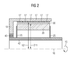
- Figure 2 shows another embodiment of a generator comprising a rotor 10 and a stator 20.
- Figure 2 shows a cross-sectional view along a rotor axis of rotation 16.
- the rotor 10 is designed as an external rotor 10. It comprises a plurality of magnets 17.
- the magnets 17 are configured as permanent magnets.
- the rotor 10 is connected with a main shaft 42 via a bearing 43.
- the stator 20 is connected with the main shaft 42 via stator side plates 25.
- the rotor 10 and the stator 20 are arranged such that a gap 30 is between them.
- a width of the gap 30 is determined, i.e. defined, by the difference between an actual inner rotor radius 121 and an actual outer stator radius 211.
- Both the rotor 10 and the stator 20 are substantially made of steel.
- Figure 3 compares an actual width of the gap 31 with a reference width of the gap 32. In other words, it shows how the width of the gap 30 changes when the temperature of the rotor 10 and the temperature of the stator 20 change.
- the following dimensions refer to a radial direction 41 which is defined as pointing radially outward of a rotor axis of rotation 16 and in a plane that is perpendicular to the rotor axis of rotation 16.
- the rotor axis of rotation 16 has to be understood as the axis about which the rotor 10 rotates while the generator, of which the rotor 10 and the stator 20 forms part, is under operation.
- the explicite figures given in the following only apply to the concrete example shown in Figure 2 .
- the rotor 10 comprises a reference inner rotor radius 122 and a reference outer rotor radius 112.
- the stator 20 comprises a reference outer stator radius 212 and a reference inner stator radius 222 at the reference temperature of 20 degrees Celsius.
- the temperature of the rotor 10 and the temperature of the stator 20 are both 20 degrees Celsius at the reference temperature.
- the value of the reference width of the gap 32 is 4 mm.
- the temperature of the stator increases to 90 degrees Celsius and the temperature of the rotor increases to 40 degrees Celsius.
- the temperature difference between the stator 20 and the rotor 10 is 50 Kelvin. Due to the increased temperatures of the rotor and the stator, both the rotor 10 and the stator 20 expand.
- the actual outer rotor radius 111 increases compared to the reference outer rotor radius 112 and the actual inner rotor radius 121 increases compared to the reference inner rotor radius 122.
- an actual outer stator radius 211 increases compared to the reference outer stator radius 212.
- the actual inner stator radius 221, however, remains unchanged compared to the reference inner stator radius 222.
- an actual width of the gap 31 shrinks, i.e. gets smaller, compared to the reference width of the gap 32.
- Figure 4 shows a diagrammatic view, i.e. a flowchart, of the method for determining the actual width of the gap between the rotor and the stator of a generator of a wind turbine under the advantageous conditions of equal thermal expansion coefficients and equal reference temperatures for stator and rotor, respectively.
- the method comprises a first step 410 where the actual temperature of the stator is measured. Furthermore, it comprises a second step 411, where the actual temperature of the rotor is measured. Subsequently, a difference between the actual temperature of the stator and the actual temperature of the rotor is performed by subtracting the temperature of the rotor from the temperature of the stator 412. Thus, a temperature difference is obtained 420.
- the obtained temperature difference is multiplied 422 with a thermal expansion coefficient of the stator 522, thus obtaining 430 an actual width difference of the gap between the rotor and the stator.
- the thermal expansion coefficient of the stator 522 is substantially equal to the thermal expansion coefficient of the rotor, as both the rotor and the stator are substantially made of the same material.
- a reference width is determined at a reference temperature by means of a length measurement of the gap, e.g. by a gauge.
- the determined reference width is added 432 to the previously obtained actual width difference of the gap.
- an actual width of the gap between the rotor and the stator is thus obtained 432.
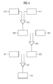
- Figure 5 shows a diagrammatic view, i.e. a flowchart, of the method for determining the actual width of the gap between the rotor and the stator of a generator of a wind turbine in a more general case.
- the method comprises a first step 410 of determining the actual temperature of the stator.
- the actual temperature of the stator is determined to be 90 degrees Celsius.
- the actual temperature of the rotor is determined in a second step 411.
- the actual temperature of the rotor is determined to be 40 degrees Celsius.
- the reference temperature of the stator is determined and in a yet another step 511, the reference temperature of the rotor is determined.
- the reference temperatures of the stator and the rotor are determined in a stand still position of the generator.
- the rotor and the stator are in thermal equilibrium during the measurement of the reference temperatures, thus both reference temperatures are equal.
- the reference temperature of the stator and the reference temperature of the rotor are determined to be 20 degrees Celsius each.
- the reference temperature of the stator is subtracted from the actual temperature of the stator.
- a temperature difference of the stator is obtained 520.
- the temperature difference of the stator is 70 degrees.
- the reference temperature of the rotor is subtracted from the actual temperature of the rotor.
- a temperature difference of the rotor is obtained 521.
- the temperature difference of the stator is 20 degrees.
- the obtained temperature difference of the stator is multiplied 524 with a thermal expansion coefficient of the stator 522, thus obtaining 530 an actual expansion of the stator.
- the obtained temperature difference of the rotor is multiplied 525 with a thermal expansion coefficient of the rotor 523, thus obtaining 531 an actual expansion of the rotor.
- the actual expansion of the stator is 1,75 mm, assuming a thermal expansion coefficient of the stator 522 of -0.025 mm per Kelvin; likewise, the actual expansion of the rotor is 1 mm, assuming a thermal expansion coefficient of the rotor 522 of -0.05 mm per Kelvin.
- step 532 actual expansion of the rotor actual expansion of the rotor is subtracted from the actual expansion of the stator, thus obtaining 430 an actual width difference of the gap between the rotor and the stator.
- the actual width difference of the gap between the rotor and the stator is 0.75 mm.
- a reference width is determined at a reference temperature by means of a length measurement of the gap, e.g. by a gauge.
- the steps 431, 510 and 511 are performed shortly one after the other.
- the determined reference width is added 432 to the previously obtained actual width difference of the gap.
- an actual width of the gap between the rotor and the stator is thus obtained 432.
Landscapes
- Engineering & Computer Science (AREA)
- Microelectronics & Electronic Packaging (AREA)
- Power Engineering (AREA)
- Physics & Mathematics (AREA)
- General Physics & Mathematics (AREA)
Priority Applications (1)
| Application Number | Priority Date | Filing Date | Title |
|---|---|---|---|
| EP13184992.9A EP2852037A1 (de) | 2013-09-18 | 2013-09-18 | Breitenbestimmung und -steuerung eines Spaltes zwischen einem Rotor und einem Stator eines Generators |
Applications Claiming Priority (1)
| Application Number | Priority Date | Filing Date | Title |
|---|---|---|---|
| EP13184992.9A EP2852037A1 (de) | 2013-09-18 | 2013-09-18 | Breitenbestimmung und -steuerung eines Spaltes zwischen einem Rotor und einem Stator eines Generators |
Publications (1)
| Publication Number | Publication Date |
|---|---|
| EP2852037A1 true EP2852037A1 (de) | 2015-03-25 |
Family
ID=49182176
Family Applications (1)
| Application Number | Title | Priority Date | Filing Date |
|---|---|---|---|
| EP13184992.9A Withdrawn EP2852037A1 (de) | 2013-09-18 | 2013-09-18 | Breitenbestimmung und -steuerung eines Spaltes zwischen einem Rotor und einem Stator eines Generators |
Country Status (1)
| Country | Link |
|---|---|
| EP (1) | EP2852037A1 (de) |
Cited By (5)
| Publication number | Priority date | Publication date | Assignee | Title |
|---|---|---|---|---|
| GB2523474A (en) * | 2014-02-19 | 2015-08-26 | Vibrosystm Inc | Real time monitoring of rotor or stator shape change for rotating machines |
| WO2018189023A1 (de) * | 2017-04-12 | 2018-10-18 | Wobben Properties Gmbh | Verfahren zum kühlen einer getriebelosen windenergieanlage |
| CN109916271A (zh) * | 2019-03-28 | 2019-06-21 | 江苏核电有限公司 | 一种计入热变形的密封瓦径向间隙的测量方法 |
| CN117606420A (zh) * | 2024-01-22 | 2024-02-27 | 湖南星创智能装备有限公司 | 一种电机的轴向间隙检测装置及设备 |
| US11952981B2 (en) | 2021-03-25 | 2024-04-09 | Wobben Properties Gmbh | Wind power installation and method for controlling a wind power installation |
Citations (3)
| Publication number | Priority date | Publication date | Assignee | Title |
|---|---|---|---|---|
| US3743934A (en) * | 1970-05-20 | 1973-07-03 | Bbc Brown Boveri & Cie | Apparatus for monitoring the air gap in rotary electrical machines using magnetic field plates or magneto diodes |
| DE19961528C1 (de) * | 1999-12-20 | 2001-06-13 | Siemens Ag | Verfahren zur Überwachung des radialen Spalts zwischen dem Rotor und dem Stator eines elektrischen Generators und Vorrichtung zur Durchführung des Verfahrens |
| DE102011077736A1 (de) * | 2011-06-17 | 2012-12-20 | Siemens Aktiengesellschaft | Abstandssensor |
-
2013
- 2013-09-18 EP EP13184992.9A patent/EP2852037A1/de not_active Withdrawn
Patent Citations (3)
| Publication number | Priority date | Publication date | Assignee | Title |
|---|---|---|---|---|
| US3743934A (en) * | 1970-05-20 | 1973-07-03 | Bbc Brown Boveri & Cie | Apparatus for monitoring the air gap in rotary electrical machines using magnetic field plates or magneto diodes |
| DE19961528C1 (de) * | 1999-12-20 | 2001-06-13 | Siemens Ag | Verfahren zur Überwachung des radialen Spalts zwischen dem Rotor und dem Stator eines elektrischen Generators und Vorrichtung zur Durchführung des Verfahrens |
| DE102011077736A1 (de) * | 2011-06-17 | 2012-12-20 | Siemens Aktiengesellschaft | Abstandssensor |
Cited By (9)
| Publication number | Priority date | Publication date | Assignee | Title |
|---|---|---|---|---|
| GB2523474A (en) * | 2014-02-19 | 2015-08-26 | Vibrosystm Inc | Real time monitoring of rotor or stator shape change for rotating machines |
| WO2018189023A1 (de) * | 2017-04-12 | 2018-10-18 | Wobben Properties Gmbh | Verfahren zum kühlen einer getriebelosen windenergieanlage |
| CN110546865A (zh) * | 2017-04-12 | 2019-12-06 | 乌本产权有限公司 | 用于冷却无传动装置的风能设施的方法 |
| US20200149514A1 (en) * | 2017-04-12 | 2020-05-14 | Wobben Properties Gmbh | Method for cooling a gearless wind turbine |
| US10961986B2 (en) * | 2017-04-12 | 2021-03-30 | Wobben Properties Gmbh | Method for cooling a gearless wind turbine |
| CN109916271A (zh) * | 2019-03-28 | 2019-06-21 | 江苏核电有限公司 | 一种计入热变形的密封瓦径向间隙的测量方法 |
| US11952981B2 (en) | 2021-03-25 | 2024-04-09 | Wobben Properties Gmbh | Wind power installation and method for controlling a wind power installation |
| CN117606420A (zh) * | 2024-01-22 | 2024-02-27 | 湖南星创智能装备有限公司 | 一种电机的轴向间隙检测装置及设备 |
| CN117606420B (zh) * | 2024-01-22 | 2024-04-26 | 湖南星创智能装备有限公司 | 一种电机的轴向间隙检测装置及设备 |
Similar Documents
| Publication | Publication Date | Title |
|---|---|---|
| EP2852037A1 (de) | Breitenbestimmung und -steuerung eines Spaltes zwischen einem Rotor und einem Stator eines Generators | |
| Mohammed et al. | Stator winding internal thermal monitoring and analysis using in situ FBG sensing technology | |
| CN110967129B (zh) | 一种高温转子系统轴向力测试系统及方法 | |
| Zhang et al. | Experimental study on pad temperature and film thickness of tilting-pad journal bearings with an elastic-pivot pad | |
| CN101458309B (zh) | 电动汽车电机驱动系统快速温升测量装置及测量方法 | |
| CN104913861B (zh) | 电动机的转子的温度检测装置和过热保护装置 | |
| US20160274192A1 (en) | Method for testing a bar winding of a rotor of a rotating electrical machine | |
| JP6249433B1 (ja) | 横流電流検出装置、横流電流検出方法、および、回転子 | |
| CN107462815B (zh) | 一种电缆绝缘热击穿电压确定方法和装置 | |
| Wang et al. | Investigation of lumped-parameter thermal model and thermal parameters test for IPMSM | |
| CN104965174A (zh) | 交流电机能效及运行性能综合测试系统 | |
| CN112147181A (zh) | 虚拟温度传感器及测温方法、电机过温防护系统和汽车 | |
| CN204575221U (zh) | 用于电机转子温升实时测量的空心共轴对拖电机试验台 | |
| JP5750820B2 (ja) | 鉄損測定方法 | |
| Xie et al. | Investigation of rotor thermal stress in squirrel cage induction motor with broken bar faults | |
| CN116078560A (zh) | 高转速-高温作用下离心机原位加热的校温装置 | |
| Kennedy et al. | Hot spot studies for sheet wound transformer windings | |
| Herman et al. | Evaluation and uncertainties of an electric direct-drive motor test system with a mathematical model confirmation | |
| EP2088410B1 (de) | Drehende elektrische Maschine | |
| Hudon et al. | On-line rotor temperature measurements | |
| KR20150076737A (ko) | 풍력 터빈의 풍력 속도 추정 장치 및 그 풍력 속도 추정 방법 | |
| EP2568583B1 (de) | Temperaturüberwachungsvorrichtung für elektrischen Motor | |
| Caetano et al. | Capacitive and inductive sensors for diagnosing air-gap anomalies in synchronous generators | |
| CN104776939A (zh) | 用于电机转子温升实时测量的空心共轴对拖电机试验台 | |
| Sniders et al. | Non-stationary Heating of Low-power Induction Motor Under Continued Overload |
Legal Events
| Date | Code | Title | Description |
|---|---|---|---|
| PUAI | Public reference made under article 153(3) epc to a published international application that has entered the european phase |
Free format text: ORIGINAL CODE: 0009012 |
|
| 17P | Request for examination filed |
Effective date: 20130918 |
|
| AK | Designated contracting states |
Kind code of ref document: A1 Designated state(s): AL AT BE BG CH CY CZ DE DK EE ES FI FR GB GR HR HU IE IS IT LI LT LU LV MC MK MT NL NO PL PT RO RS SE SI SK SM TR |
|
| AX | Request for extension of the european patent |
Extension state: BA ME |
|
| GRAP | Despatch of communication of intention to grant a patent |
Free format text: ORIGINAL CODE: EPIDOSNIGR1 |
|
| R17P | Request for examination filed (corrected) |
Effective date: 20150918 |
|
| RBV | Designated contracting states (corrected) |
Designated state(s): AL AT BE BG CH CY CZ DE DK EE ES FI FR GB GR HR HU IE IS IT LI LT LU LV MC MK MT NL NO PL PT RO RS SE SI SK SM TR |
|
| INTG | Intention to grant announced |
Effective date: 20151023 |
|
| RIC1 | Information provided on ipc code assigned before grant |
Ipc: G01B 21/16 20060101ALI20151009BHEP Ipc: G01B 5/00 20060101ALI20151009BHEP Ipc: H02K 7/18 20060101ALN20151009BHEP Ipc: H02K 11/00 20060101AFI20151009BHEP |
|
| STAA | Information on the status of an ep patent application or granted ep patent |
Free format text: STATUS: THE APPLICATION IS DEEMED TO BE WITHDRAWN |
|
| 18D | Application deemed to be withdrawn |
Effective date: 20160303 |