EP2851886A1 - Arrangement in a vehicle for providing vehicle driver support, a vehicle, and a method for providing vehicle driver support - Google Patents
Arrangement in a vehicle for providing vehicle driver support, a vehicle, and a method for providing vehicle driver support Download PDFInfo
- Publication number
- EP2851886A1 EP2851886A1 EP13185078.6A EP13185078A EP2851886A1 EP 2851886 A1 EP2851886 A1 EP 2851886A1 EP 13185078 A EP13185078 A EP 13185078A EP 2851886 A1 EP2851886 A1 EP 2851886A1
- Authority
- EP
- European Patent Office
- Prior art keywords
- vehicle
- information
- route
- preceding vehicle
- host vehicle
- Prior art date
- Legal status (The legal status is an assumption and is not a legal conclusion. Google has not performed a legal analysis and makes no representation as to the accuracy of the status listed.)
- Granted
Links
- 238000000034 method Methods 0.000 title claims abstract description 17
- 238000004891 communication Methods 0.000 claims abstract description 57
- 238000012545 processing Methods 0.000 claims abstract description 41
- 230000008569 process Effects 0.000 claims abstract description 5
- 238000013459 approach Methods 0.000 description 5
- 230000001133 acceleration Effects 0.000 description 3
- 238000001514 detection method Methods 0.000 description 2
- 231100001261 hazardous Toxicity 0.000 description 2
- 238000012986 modification Methods 0.000 description 2
- 230000004048 modification Effects 0.000 description 2
- 230000004075 alteration Effects 0.000 description 1
- 238000004458 analytical method Methods 0.000 description 1
- 230000008859 change Effects 0.000 description 1
- 238000004590 computer program Methods 0.000 description 1
- 238000010276 construction Methods 0.000 description 1
- 230000002349 favourable effect Effects 0.000 description 1
- 238000004556 laser interferometry Methods 0.000 description 1
- 238000004804 winding Methods 0.000 description 1
Images


Classifications
-
- G—PHYSICS
- G01—MEASURING; TESTING
- G01C—MEASURING DISTANCES, LEVELS OR BEARINGS; SURVEYING; NAVIGATION; GYROSCOPIC INSTRUMENTS; PHOTOGRAMMETRY OR VIDEOGRAMMETRY
- G01C21/00—Navigation; Navigational instruments not provided for in groups G01C1/00 - G01C19/00
- G01C21/26—Navigation; Navigational instruments not provided for in groups G01C1/00 - G01C19/00 specially adapted for navigation in a road network
- G01C21/34—Route searching; Route guidance
- G01C21/36—Input/output arrangements for on-board computers
- G01C21/3697—Output of additional, non-guidance related information, e.g. low fuel level
-
- B—PERFORMING OPERATIONS; TRANSPORTING
- B60—VEHICLES IN GENERAL
- B60W—CONJOINT CONTROL OF VEHICLE SUB-UNITS OF DIFFERENT TYPE OR DIFFERENT FUNCTION; CONTROL SYSTEMS SPECIALLY ADAPTED FOR HYBRID VEHICLES; ROAD VEHICLE DRIVE CONTROL SYSTEMS FOR PURPOSES NOT RELATED TO THE CONTROL OF A PARTICULAR SUB-UNIT
- B60W40/00—Estimation or calculation of non-directly measurable driving parameters for road vehicle drive control systems not related to the control of a particular sub unit, e.g. by using mathematical models
- B60W40/02—Estimation or calculation of non-directly measurable driving parameters for road vehicle drive control systems not related to the control of a particular sub unit, e.g. by using mathematical models related to ambient conditions
- B60W40/04—Traffic conditions
-
- B—PERFORMING OPERATIONS; TRANSPORTING
- B60—VEHICLES IN GENERAL
- B60W—CONJOINT CONTROL OF VEHICLE SUB-UNITS OF DIFFERENT TYPE OR DIFFERENT FUNCTION; CONTROL SYSTEMS SPECIALLY ADAPTED FOR HYBRID VEHICLES; ROAD VEHICLE DRIVE CONTROL SYSTEMS FOR PURPOSES NOT RELATED TO THE CONTROL OF A PARTICULAR SUB-UNIT
- B60W50/00—Details of control systems for road vehicle drive control not related to the control of a particular sub-unit, e.g. process diagnostic or vehicle driver interfaces
- B60W50/08—Interaction between the driver and the control system
- B60W50/14—Means for informing the driver, warning the driver or prompting a driver intervention
-
- G—PHYSICS
- G08—SIGNALLING
- G08G—TRAFFIC CONTROL SYSTEMS
- G08G1/00—Traffic control systems for road vehicles
- G08G1/16—Anti-collision systems
- G08G1/161—Decentralised systems, e.g. inter-vehicle communication
- G08G1/162—Decentralised systems, e.g. inter-vehicle communication event-triggered
-
- G—PHYSICS
- G08—SIGNALLING
- G08G—TRAFFIC CONTROL SYSTEMS
- G08G1/00—Traffic control systems for road vehicles
- G08G1/16—Anti-collision systems
- G08G1/166—Anti-collision systems for active traffic, e.g. moving vehicles, pedestrians, bikes
-
- G—PHYSICS
- G08—SIGNALLING
- G08G—TRAFFIC CONTROL SYSTEMS
- G08G1/00—Traffic control systems for road vehicles
- G08G1/16—Anti-collision systems
- G08G1/167—Driving aids for lane monitoring, lane changing, e.g. blind spot detection
-
- B—PERFORMING OPERATIONS; TRANSPORTING
- B60—VEHICLES IN GENERAL
- B60W—CONJOINT CONTROL OF VEHICLE SUB-UNITS OF DIFFERENT TYPE OR DIFFERENT FUNCTION; CONTROL SYSTEMS SPECIALLY ADAPTED FOR HYBRID VEHICLES; ROAD VEHICLE DRIVE CONTROL SYSTEMS FOR PURPOSES NOT RELATED TO THE CONTROL OF A PARTICULAR SUB-UNIT
- B60W50/00—Details of control systems for road vehicle drive control not related to the control of a particular sub-unit, e.g. process diagnostic or vehicle driver interfaces
- B60W50/08—Interaction between the driver and the control system
- B60W50/14—Means for informing the driver, warning the driver or prompting a driver intervention
- B60W2050/146—Display means
-
- B—PERFORMING OPERATIONS; TRANSPORTING
- B60—VEHICLES IN GENERAL
- B60W—CONJOINT CONTROL OF VEHICLE SUB-UNITS OF DIFFERENT TYPE OR DIFFERENT FUNCTION; CONTROL SYSTEMS SPECIALLY ADAPTED FOR HYBRID VEHICLES; ROAD VEHICLE DRIVE CONTROL SYSTEMS FOR PURPOSES NOT RELATED TO THE CONTROL OF A PARTICULAR SUB-UNIT
- B60W2554/00—Input parameters relating to objects
- B60W2554/80—Spatial relation or speed relative to objects
- B60W2554/801—Lateral distance
-
- B—PERFORMING OPERATIONS; TRANSPORTING
- B60—VEHICLES IN GENERAL
- B60W—CONJOINT CONTROL OF VEHICLE SUB-UNITS OF DIFFERENT TYPE OR DIFFERENT FUNCTION; CONTROL SYSTEMS SPECIALLY ADAPTED FOR HYBRID VEHICLES; ROAD VEHICLE DRIVE CONTROL SYSTEMS FOR PURPOSES NOT RELATED TO THE CONTROL OF A PARTICULAR SUB-UNIT
- B60W2554/00—Input parameters relating to objects
- B60W2554/80—Spatial relation or speed relative to objects
- B60W2554/804—Relative longitudinal speed
-
- B—PERFORMING OPERATIONS; TRANSPORTING
- B60—VEHICLES IN GENERAL
- B60W—CONJOINT CONTROL OF VEHICLE SUB-UNITS OF DIFFERENT TYPE OR DIFFERENT FUNCTION; CONTROL SYSTEMS SPECIALLY ADAPTED FOR HYBRID VEHICLES; ROAD VEHICLE DRIVE CONTROL SYSTEMS FOR PURPOSES NOT RELATED TO THE CONTROL OF A PARTICULAR SUB-UNIT
- B60W2556/00—Input parameters relating to data
- B60W2556/45—External transmission of data to or from the vehicle
- B60W2556/50—External transmission of data to or from the vehicle of positioning data, e.g. GPS [Global Positioning System] data
-
- B—PERFORMING OPERATIONS; TRANSPORTING
- B60—VEHICLES IN GENERAL
- B60W—CONJOINT CONTROL OF VEHICLE SUB-UNITS OF DIFFERENT TYPE OR DIFFERENT FUNCTION; CONTROL SYSTEMS SPECIALLY ADAPTED FOR HYBRID VEHICLES; ROAD VEHICLE DRIVE CONTROL SYSTEMS FOR PURPOSES NOT RELATED TO THE CONTROL OF A PARTICULAR SUB-UNIT
- B60W2556/00—Input parameters relating to data
- B60W2556/45—External transmission of data to or from the vehicle
- B60W2556/65—Data transmitted between vehicles
-
- B—PERFORMING OPERATIONS; TRANSPORTING
- B60—VEHICLES IN GENERAL
- B60W—CONJOINT CONTROL OF VEHICLE SUB-UNITS OF DIFFERENT TYPE OR DIFFERENT FUNCTION; CONTROL SYSTEMS SPECIALLY ADAPTED FOR HYBRID VEHICLES; ROAD VEHICLE DRIVE CONTROL SYSTEMS FOR PURPOSES NOT RELATED TO THE CONTROL OF A PARTICULAR SUB-UNIT
- B60W30/00—Purposes of road vehicle drive control systems not related to the control of a particular sub-unit, e.g. of systems using conjoint control of vehicle sub-units
- B60W30/18—Propelling the vehicle
- B60W30/18009—Propelling the vehicle related to particular drive situations
- B60W30/18163—Lane change; Overtaking manoeuvres
Definitions
- Embodiments herein relate to an arrangement in a vehicle for providing vehicle driver support. Embodiments herein further relate to a vehicle comprising an arrangement in a vehicle for providing vehicle driver support and to a method for providing vehicle driver support.
- a vehicle When driving along a route on a road, it is common that a vehicle catches up another slower vehicle which is driving along the same route in the same direction. In case the road has at least two lanes in the same direction, the faster vehicle may change lane in order to pass the slower vehicle in an adjacent lane.
- a driver of a vehicle is catching up a slower vehicle on a road with only one lane in each direction, or on a road with a broad common lane for two different driving directions, the driver may intend to overtake the slower vehicle ahead using a lane, or part of a lane, which is normally used by oncoming vehicles, driving in the opposite direction.
- a driver may overtake a large vehicle ahead, such as a truck, bus or tractor, since a long vehicle ahead requires longer passing time, and since a broad vehicle ahead may occupy a large portion of a width of the road.
- large vehicles may obstruct a big part of the view for a vehicle approaching from the rear.
- Embodiments herein aim to provide an arrangement in a vehicle for providing vehicle driver support eliminating or at least reducing the problems and/or drawbacks associated with overtaking scenarios.
- an arrangement in a vehicle for providing vehicle driver support during manual or semi-autonomous driving in a potential overtake scenario wherein the arrangement comprises;
- the vehicle driver Since the probability that the preceding vehicle will drive along the one or more route ahead of the host vehicle is determined and arranged to be displayed, the vehicle driver is supported such that unnecessary overtaking's may be avoided.
- An “unnecessary overtake” may be an overtake that a driver of the host vehicle wouldn't have performed if he/she had known that a route of a preceding vehicle coincides with the host vehicle route only for a relatively short distance ahead of the host vehicle.
- An “unnecessary overtake” may also be an overtake which results in a relatively small saving of time compared with a scenario wherein no overtake was performed.
- a host vehicle may lower a host vehicle speed into a speed which is substantially the same or lower than the speed of the preceding vehicle.
- the driver of the host vehicle may overtake the preceding vehicle by keeping a current speed or accelerate into a higher speed than the speed of the preceding vehicle.
- a host vehicle driver often accelerates in order to speed up the overtake and thereby decrease the time and distance needed for the overtake.
- the host vehicle driver In the scenario wherein the driver of a host vehicle approaches a slower driving vehicle from behind, the host vehicle driver normally is unaware of the route of the preceding vehicle, i.e. which road the driver of the preceding vehicle intends to drive, as well as the intended destination for the preceding vehicle.
- This lack of information may result in that the host vehicle initiates an overtake although the driver of the preceding vehicle intends to leave the host vehicle route and continue on another route than the host vehicle driver in a relatively short distance, for example within a few hundred meters, a few kilometres or a few tens of kilometres.
- the saving of time thanks to the overtake may then be relatively small, such as only one or a few per cent or a few ten per cents of the time needed for driving the route.
- probable routes of two or more preceding vehicles are determined.
- a host vehicle driver Since probable routes of two or more preceding vehicles are determined, a host vehicle driver is supported in a situation where he/she decide whether to overtake two or more preceding vehicles. This is very useful in a scenario where the host vehicle approaches two or more vehicles driving on a road ahead of the host vehicle.
- the communication unit is arranged to send a request to the one or more preceding vehicles in order to receive the information on the one or more probable routes for the one or more preceding vehicles.
- the communication unit is arranged to send a request to the one or more preceding vehicles in order to receive the route information, the preceding vehicles doesn't have to send out the information continuously but only when a request from another vehicle is received.
- the communication unit is arranged to communicate with other vehicles via vehicle-to-vehicle-communication (V2V).
- V2V vehicle-to-vehicle-communication
- V2V vehicle-to-vehicle-communication
- the communication unit is arranged to communicate with other vehicles via vehicle-to-infrastructure-to-vehicle-communication (V2I2V).
- V2I2V vehicle-to-infrastructure-to-vehicle-communication
- the infrastructure may be e.g. roadside units, arranged in the vicinity of a road and arranged to communicate signals between the vehicles.
- the roadside units may comprise any suitable communication equipment, including senders and receivers.
- the infrastructure may also be one or more remotely arranged servers, comprising or connected to any suitable communication equipment, including senders and receivers.
- the one or more display units are arranged to display the processed information only if a, by the detector, detected distance between the host vehicle and the preceding vehicle is below a threshold distance.
- the one or more display units are arranged to display the processed information only if a distance between the host vehicle and the preceding vehicle is below a threshold distance, the vehicle driver is informed only when he/she needs the information. Thanks to this, the driver may be presented with a well-balanced load of information, and the driver doesn't have to pay any attention to information relating to preceding vehicles when no preceding vehicle is within the threshold distance.
- the threshold distance may be pre-configured or user-configured to any desired distance.
- the arrangement comprises a positioning system connected to a map database, arranged to continuously determine a host vehicle position.
- a map database may be e.g. a database comprising map information stored on one or more servers.
- the map information may comprise information of a host vehicle surrounding, a region, a country or global map information.
- the information may be provided by a third party.
- the map database may also be an in-vehicle-stored database and/or a database comprising information collected during routes driven previously by the host vehicle or vehicles connected to the host vehicle.
- the one or more display units are arranged to display the information graphically and where a first graphical element represents the probability that the preceding vehicle will drive along a first route, and a second graphical element represents the probability that the preceding vehicle will drive along a second route.
- a graphical element may be e.g. a line, an arrow a dot, a sign or a symbol.
- an arrow pointing upwards on the display may represent a route or road ahead of the host vehicle.
- An arrow pointing to the right may represent a route or road turning to the right, or a route or road that follows a route or road ahead and then is turning right from the route or road ahead.
- the route or road ahead may be the host vehicle route or any other route, such as the largest road or route.
- a graphical element may also be a number, or a number with a per cent sign, e.g. 10%, 50%, 72% or 100%. The graphical element may then be indicative of the probability that the preceding vehicle will drive along a particular route.
- the host vehicle positioning system connected to the map database is arranged to receive a host vehicle route
- the processing unit is arranged to compare the host vehicle route with the determined routes of the one or more preceding vehicles and the one or more display units are arranged to display information indicative of a distance for which the two or more routes coincide.
- the vehicle driver may be informed of the distance for which the preceding vehicle will continue to drive in front of the host vehicle. Thereby the driver is supported in a decision whether to overtake the preceding vehicle or not.
- the map database connected host vehicle positioning system is arranged to receive a host vehicle route
- the processing unit is arranged to compare the host vehicle route with the determined routes of the one or more preceding vehicles
- the one or more display units are arranged to display information indicative of the probability that the one or more preceding vehicles will drive along the host vehicle route for any selected distance along the host vehicle route.
- the vehicle driver selects the distance "1km”, he/she may see the probability, e.g. "50%” on a display. Thus, the probability that the preceding vehicle will continue on the host vehicle route for the upcoming kilometre is determined to be 50%. If the vehicle driver instead selects the distance "5km”, he/she may see the probability, e.g. "20%” on a display. Thus, the probability that the preceding vehicle will continue on the host vehicle route for the next 5 kilometres is determined to be 20%.
- Embodiments herein also aim to provide a vehicle comprising an arrangement for providing a vehicle driver with support during manual or semi-autonomous driving in a potential overtake scenario without the problems or drawbacks described above.
- a vehicle comprising an arrangement for providing vehicle driver support during manual or semi-autonomous driving in a potential overtake scenario according to embodiments disclosed herein.
- the vehicle driver is supported such that unnecessary overtaking's may be avoided.
- Embodiments herein also aim to provide a method for providing vehicle driver support during manual or semi-autonomous driving in a potential overtake scenario without the problems or drawbacks described above.
- this is provided by a method for providing vehicle driver support during manual or semi-autonomous driving in a potential overtake scenario, the method comprises;
- the vehicle driver Since the probability that the preceding vehicle will drive along the one or more route is determined and displayed in the method, the vehicle driver is supported such that unnecessary overtaking's may be avoided.
- Fig. 1 illustrates an arrangement 1 in a vehicle 2 for providing vehicle driver support during manual or semi-autonomous driving in a potential overtake scenario.
- a driver operates driving functions of the vehicle, such as speed, acceleration, braking and steering.
- the driver may receive input from various vehicle systems, such as information-systems and warning-systems, and the driver may choose if he/she will drive in accordance with received warnings, instructions or the like.
- Semi-autonomous driving refers to scenarios where a vehicle is subject to a combined manual and autonomous input during essentially manual driving.
- a driver may use vehicle systems which may assist him/her to e.g. keep a selected speed, keep a safety distance to a preceding vehicle, automatically brake in imminent collision scenarios etc., but where the supporting vehicle systems generally are subordinated the control of the driver.
- Fig. 1 the potential overtake scenario is illustrated in a situation where the host vehicle 2 approaches a preceding vehicle 3 from the rear when both vehicles drive along a route or road in a road environment.
- the arrangement 1 comprises a detector 4, arranged to detect at least one of a closing velocity between the host vehicle 2 and the preceding vehicle 3 and a distance between the host vehicle 2 and the preceding vehicle 3.
- the detector 4 is arranged in the vicinity of a host vehicle windshield, but in other embodiments the detector 4 may be arranged in other suitable locations, such as near a vehicle grille or behind a dashboard or centerstack. The location of the detector 4 may depend of the type of detector 4 used.
- the detector 4 may be any device suitable for detecting at least one of a closing velocity between the host vehicle 2 and the preceding vehicle 3 and a distance between the host vehicle 2 and the preceding vehicle 3.
- the detector 4 may be an image capturing unit, such as a front-facing camera, connected to a processing unit with logic to analyse images taken by the image capturing unit for the determination of the closing velocity and/or the distance to the preceding vehicle 3.
- the detector 4 may be a radar transmitter/antenna, using radio waves to determine e.g. a position, direction, or speed of objects.
- the radar transmitter/antenna may transmit pulses of radio waves or microwaves which bounce off the preceding vehicle 3 in their path.
- the preceding vehicle 3 then reflects part of the wave's energy to the antenna of the detector 4 which is usually located at the same place as the transmitter of the detector 4.
- a closing velocity/a distance may be determined.
- the detector 4 may use lidar, (Laser Interferometry Detection and Ranging) for illuminating the preceding vehicle 3 with a laser and analyze the reflected light.
- lidar Laser Interferometry Detection and Ranging
- the detector 4 may detect closing velocities and/or distances between vehicles through detecting signals from surrounding vehicles, such as the preceding vehicle 3. If one or more surrounding/preceding vehicles 3 send out information of themselves, this may be detected by the host vehicle detector 4.
- the detector 4 may comprise or be connected to a communication unit in order to carry out the detection. Signals sent directly from surrounding vehicles (vehicle-to-vehicle - V2V) may be detected by the detector 4.
- V2I2V vehicle-to-infrastructure-to-vehicle
- the infrastructure may be one or more roadside units arranged to transmit communication between vehicles driving along a road. It may also be one or more external servers, which also may be referred to as a cloud.
- a mobile network such as 3G or 4G/LTE may be used for the communication between the host vehicle 2 and the infrastructure and/or surrounding vehicles. According to some embodiments, a combination of V2V and V2I2V may be used.
- a communication unit 5 of the arrangement 1 is arranged to receive from the preceding vehicle 3 information of a probable route of the preceding vehicle 3 based on at least one of preceding vehicle historical route information and preceding vehicle navigation system information.
- the communication unit 5 may comprise a receiver that receives signals from surrounding vehicles/the preceding vehicle 3 and converts them to information, such as information relating to surrounding/preceding vehicle speed, acceleration, braking, statuses, routes etc.
- the receiver may also be configured to communicate with infrastructure such as remote servers, databases, clouds and/or roadside units.
- the communication unit 5 may also comprise a transmitter which converts host vehicle information, e.g. relating to host vehicle speed, acceleration, braking, statuses, routes etc. into a signal, such as an electrical signal and/or a signal carried by electromagnetic waves.
- host vehicle information may be distributed to other vehicles and/or infrastructure such as remote servers, databases, clouds and/or roadside units.
- radio signals such as according to either of standards, such as the GSM, 3G, LTE and/or WiFi standards, and/or satellite communication signals.
- the communication unit 5 may receive information of a probable route of the preceding vehicle 3 based on preceding vehicle historical route information received from the preceding vehicle 3.
- Preceding vehicle historical route information is information relating to routes previously driven by the preceding vehicle 3.
- the information may have been gathered via a preceding vehicle positioning device connected to a database.
- the information may be stored in the vehicle or at a remote location, such as a server.
- the database may e.g. be a database with information gathered by the vehicle, or a map database provided by a third party.
- the communication unit 5 is connected to the detector 4, thereby allowing the detector 4 to detect signals sent from surrounding/preceding vehicles and communicated to the detector 4 via the communication unit 5.
- the arrangement 1 may determine probable future routes for the preceding vehicle 3 from the preceding vehicle historical route information. If the preceding vehicle 3 for example historically has turned right in a T-crossing along the route eight times out of ten, the arrangement 1 may determine that the probability that the preceding vehicle 3 will turn right in the same T-crossing a next time is 80%. If the preceding vehicle 3 then has turned left in a four-way-crossing half of the times earlier, the probability that the preceding vehicle will turn left in the four-way-crossing when driving in front of the host vehicle 2 may be determined to 50%.
- the communication unit 5 may receive information on a probable route of the preceding vehicle 3 based on received preceding vehicle navigation system information. If an occupant of the receiving vehicle 3 has inputted a desired driving route in the preceding vehicle navigation system, the arrangement 1 which receive this information may determine that the probability that the preceding vehicle 3 will drive along that route is high, such as e.g. 90%, 99% or 100%.
- Received preceding vehicle historical route information may be used together with the received preceding vehicle navigation system information for the determination.
- the arrangement 2 may determine that the probability that the preceding vehicle 3 will turn right is high.
- the processing unit 6 is arranged to receive information from the detector 4, indicative of at least one of a closing velocity between the host vehicle and the preceding vehicle and a distance between the host vehicle and the preceding vehicle.
- the processing unit 6 may be a central processor/processing unit, CPU.
- a CPU may be hardware that carries out instructions of a computer program/software when this is executed by performing basic arithmetical, logical, and input/output operations.
- the processing unit 6 may also comprise an accelerated/advanced processing unit, APU.
- An APU may include additional processing capability designed to accelerate one or more types of computations outside of a CPU.
- the processing unit 6 may also comprise an application programming interface, API, which specifies how software components may interact with each other.
- the processing unit 6 is arranged to trigger the communication unit 5 to receive information on a probable route of the preceding vehicle 3 if a detected closing velocity between the host vehicle 2 and the preceding vehicle 3 is above a threshold closing velocity or if a detected distance between the host vehicle 2 and the preceding vehicle 3 is below a threshold distance.
- the processing unit 6 is also arranged to determine, for one or more routes ahead of the host vehicle 2, the probability that the preceding vehicle 3 will drive along the one or more route, and to process the received information into a format suitable for display.
- the arrangement 1 further comprises one or more display units 7 , arranged to receive determined preceding vehicle route information from the processing unit 6 and to display the processed information such that a vehicle driver is supported.
- a head up display 7a, a driver information display 7b and a display 7c arranged in the vicinity of a dashboard/centerstack are illustrated.
- the information indicative of the probable route may be displayed selectively on one or more of the displays such that a vehicle driver may receive the information.
- the embodiment illustrated in Fig. 1 also comprises a positioning system 8 connected to a map database 9, and arranged to continuously determine a host vehicle position.
- the one or more display units 7 are arranged to display the information indicative of a determined host vehicle route graphically.
- a first graphical element 10a is used to represent the probability that the preceding vehicle 3 will drive along a first route 11a
- a second graphical element 10b is used to represent the probability that the preceding vehicle will drive along a second route 11b.
- the probability that the preceding vehicle 3 will turn right and follow the second route 11b is determined to be 10%. This probability is illustrated on the display 7c.
- the probability that the preceding vehicle 3 will continue on the first route 11a is determined to be 85%, and the probability that the preceding vehicle will turn to the left on a third (not shown) upcoming route is determined to be 5%. At least when the preceding vehicle 3 has passed a route, the probabilities that the preceding vehicle 3 will continue on other routes are updated.
- the host vehicle positioning system 8 may be arranged to receive a host vehicle route, e.g. inputted by a vehicle occupant or based on historical route data.
- the processing unit 6 will then be arranged to compare the host vehicle route with the determined routes of the one or more preceding vehicles 3.
- the one or more display units 7 are then arranged to display information indicative of a distance for which the two or more routes coincide.
- the host vehicle positioning system 8 is arranged to receive a host vehicle route, e.g. inputted by a vehicle occupant or based on historical route data.
- the processing unit 6 is then arranged to compare the host vehicle route with the determined routes of the one or more preceding vehicles 3.
- the one or more display units 7 will furhter be arranged to display information indicative of the probability that the one or more preceding vehicles 3 will drive along the host vehicle route for any selected distance along the host vehicle route.
- the one or more display units 7 are arranged to display the processed information only if a, by the detector 4, detected distance between the host vehicle 2 and the preceding vehicle 3 is below a threshold distance.
- a display unit 7otherwise displaying other information may then instead be arranged to display the preceding vehicle route information.
- Fig. 2 illustrates a host vehicle 2 and a preceding vehicle 3 in a road environment.
- a communication unit in the host vehicle 2 is arranged to receive information on a probable route of the preceding vehicle 3 from the surrounding vehicle 3. As illustrated in Fig. 2 , the information may be communicated via V2V-communication and/or V2I2V-communication.
- V2V-communication e.g. a standardized protocol for information exchange between vehicles, 802.11 p may be used.
- one or more roadside units 12 may be used, which are arranged to transmit communication between vehicles driving along a road.
- the roadside units will comprise transmitters/receivers for the communication and will be arranged along a road or road network.
- the servers 13 comprise or are connected to transmitters/receivers such that they may transmit information between vehicles.
- the one or more servers 13 may also may be referred to as a cloud.
- a mobile network such as 3G or 4G/LTE can be used for the communication between the host vehicle 2 and the roadside units 12, the servers 13 and/or surrounding vehicles such as the preceding vehicle 3.
- a combination of V2V and V2I2V will be used. V2V will then be used when a distance between vehicles is relatively small and V2I2V may be used for communication over longer distances.
- the communication unit in the host vehicle 2 is arranged to transmit signals indicative of host vehicle route information.
- drivers of vehicles rear of the host vehicle may use the information for overtaking decisions.
- the communication unit is arranged to send a request to the one or more preceding vehicles 3 in order to receive the information on the one or more probable routes for the one or more preceding vehicles 3.
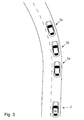
- Fig. 3 is illustrated a scenario where the host vehicle 2 approaches three preceding vehicles 3a, 3b, 3c from the rear.
- the host vehicle 2 comprises an arrangement for providing vehicle driver support as described above. Preceding vehicle 3a is closest to the host vehicle 2 and preceding vehicle 3c is farthest away from the host vehicle 2.
- the detector of the arrangement in the host vehicle 2 is arranged to detect at least one of a closing velocity between the host vehicle 2 and a preceding vehicle 3 and a distance between the host vehicle 2 and a preceding vehicle 3.
- the detector may detect the closing velocity/the distance to the closest preceding vehicle 3a.
- the communication unit of the arrangement in the host vehicle 2 is arranged to receive from the preceding vehicles 3a, 3b, 3c information of one or more probable routes of the preceding vehicles 3a, 3b, 3c based on at least one of received preceding vehicles 3a, 3b, 3c historical route information and received preceding vehicles 3a, 3b, 3c navigation system information.
- the processing unit of the arrangement in the host vehicle 2 is arranged to receive from the detector information indicative of at least one of a closing velocity between the host vehicle 2 and the preceding vehicles 3a, 3b, 3c and a distance between the host vehicle 2 and the preceding vehicles 3a, 3b, 3c.
- the processing unit may then trigger the communication unit to receive information on one or more probable routes of the preceding vehicles 3a, 3b, 3c if a detected closing velocity between the host vehicle 2 and one of the preceding vehicles 3a, 3b, 3c, such as the closest preceding vehicle 3a, is above a threshold closing velocity.
- the processing unit may then trigger the communication unit to receive information on one or more probable routes of the preceding vehicles 3a, 3b, 3c if a detected distance between the host vehicle 2 and a preceding vehicle3 a, 3b, 3c, such as the closest preceding vehicle 3a, is below a threshold distance.
- a threshold closing velocity and/or a threshold distance may be pre-configured or user-configured, and may be any suitable velocity/distance.
- the processing unit of the arrangement in the host vehicle 2 is arranged to determine, for one or more routes ahead of the host vehicle 2, the probability that the preceding vehicle 3a, 3b, 3c will drive along the one or more route. The determination is based on at least one of received preceding vehicles historical route information data and received preceding vehicles navigation system information. The processing unit of the arrangement in the host vehicle 2 will then process the received information into a format suitable for display.
- One or more display units of the arrangement in the host vehicle 2 will receive determined preceding vehicles route information from the processing unit and display the processed information such that a host vehicle driver will be supported in his/her decisions whether to initiate an overtake or not.
- the host vehicle driver will receive information indicative of a distance for which the host vehicle routes coincide with determined routes for the preceding vehicles 3a, 3b, 3c.
- the probabilities that the preceding vehicles 3a, 3b, 3c will drive along a specific route respectively, such as the host vehicle route, will be used for determination of an aggregated probability that some or all of the preceding vehicles 3 will drive along the specific route for any selected distance.
- Fig. 4 illustrates a method 100 for providing vehicle driver support during manual or semi-autonomous driving in a potential overtake scenario, characterized in that the method comprises;
Landscapes
- Engineering & Computer Science (AREA)
- Physics & Mathematics (AREA)
- General Physics & Mathematics (AREA)
- Automation & Control Theory (AREA)
- Transportation (AREA)
- Mechanical Engineering (AREA)
- Radar, Positioning & Navigation (AREA)
- Remote Sensing (AREA)
- Mathematical Physics (AREA)
- Human Computer Interaction (AREA)
- Traffic Control Systems (AREA)
Abstract
Description
- Embodiments herein relate to an arrangement in a vehicle for providing vehicle driver support. Embodiments herein further relate to a vehicle comprising an arrangement in a vehicle for providing vehicle driver support and to a method for providing vehicle driver support.
- When driving along a route on a road, it is common that a vehicle catches up another slower vehicle which is driving along the same route in the same direction. In case the road has at least two lanes in the same direction, the faster vehicle may change lane in order to pass the slower vehicle in an adjacent lane.
- If a driver of a vehicle is catching up a slower vehicle on a road with only one lane in each direction, or on a road with a broad common lane for two different driving directions, the driver may intend to overtake the slower vehicle ahead using a lane, or part of a lane, which is normally used by oncoming vehicles, driving in the opposite direction.
- During relatively straight road sections, where the vehicle driver can see the road well ahead of his/her vehicle, an overtake of a slower driving vehicle ahead is often relatively easy. During less favourable circumstances, it may be more hazardous to perform an overtake of a vehicle ahead. On winding roads, it may be difficult to overlook the entire distance required for the overtake, since curves and brows of a hill may decrease a visible road section ahead. During conditions with reduced sight, such as during dusk, dawn, night, rain or fog, it may be difficult both to gain sight of the road ahead and to estimate a distance to a detected oncoming vehicle.
- It may also be a challenge for a driver to overtake a large vehicle ahead, such as a truck, bus or tractor, since a long vehicle ahead requires longer passing time, and since a broad vehicle ahead may occupy a large portion of a width of the road. In addition, large vehicles may obstruct a big part of the view for a vehicle approaching from the rear.
- A situation in which a driver of a faster vehicle catches up a slower vehicle on a road section where an overtake is difficult or hazardous may be frustrating for the driver in the faster vehicle. If he/she is stressed or inexperienced, there may be a risk that he/she initiates an overtake although conditions are less than optimal if he/she believes that a considerable time amount is gained thanks to the overtake. Thus, improvements in the field of vehicle safety in overtaking scenarios are desirable.
- Embodiments herein aim to provide an arrangement in a vehicle for providing vehicle driver support eliminating or at least reducing the problems and/or drawbacks associated with overtaking scenarios.
- According to an embodiment, this is provided by an arrangement in a vehicle for providing vehicle driver support during manual or semi-autonomous driving in a potential overtake scenario, wherein the arrangement comprises;
- a detector, arranged to detect at least one of a closing velocity between the host vehicle and a preceding vehicle and a distance between the host vehicle and the preceding vehicle,
- a communication unit, arranged to receive from the preceding vehicle information of a probable route of the preceding vehicle based on at least one of preceding vehicle historical route information and preceding vehicle navigation system information,
- a processing unit, arranged to; receive information indicative of at least one of a closing velocity between the host vehicle and the preceding vehicle and a distance between the host vehicle and the preceding vehicle from the detector; trigger the communication unit to receive information on a probable route of a preceding vehicle if a detected closing velocity between the host vehicle and the preceding vehicle is above a threshold closing velocity or if a detected distance between the host vehicle and the preceding vehicle is below a threshold distance; determine, for one or more routes ahead of the host vehicle, the probability that the preceding vehicle will drive along the one or more route, the determination being based on at least one of received preceding vehicle historical route information data and received preceding vehicle navigation system information, and to process the received information into a format suitable for display,
- one or more display units, arranged to receive determined preceding vehicle route information from the processing unit and to display the processed information,
- Since the probability that the preceding vehicle will drive along the one or more route ahead of the host vehicle is determined and arranged to be displayed, the vehicle driver is supported such that unnecessary overtaking's may be avoided.
- An "unnecessary overtake" may be an overtake that a driver of the host vehicle wouldn't have performed if he/she had known that a route of a preceding vehicle coincides with the host vehicle route only for a relatively short distance ahead of the host vehicle. An "unnecessary overtake" may also be an overtake which results in a relatively small saving of time compared with a scenario wherein no overtake was performed.
- In a scenario wherein the driver of a host vehicle approaches a slower vehicle from behind on a road, i.e. a preceding vehicle, he/she may lower a host vehicle speed into a speed which is substantially the same or lower than the speed of the preceding vehicle. Alternatively, the driver of the host vehicle may overtake the preceding vehicle by keeping a current speed or accelerate into a higher speed than the speed of the preceding vehicle. During an overtake a host vehicle driver often accelerates in order to speed up the overtake and thereby decrease the time and distance needed for the overtake.
- In the scenario wherein the driver of a host vehicle approaches a slower driving vehicle from behind, the host vehicle driver normally is unaware of the route of the preceding vehicle, i.e. which road the driver of the preceding vehicle intends to drive, as well as the intended destination for the preceding vehicle. This lack of information may result in that the host vehicle initiates an overtake although the driver of the preceding vehicle intends to leave the host vehicle route and continue on another route than the host vehicle driver in a relatively short distance, for example within a few hundred meters, a few kilometres or a few tens of kilometres. The saving of time thanks to the overtake may then be relatively small, such as only one or a few per cent or a few ten per cents of the time needed for driving the route.
- Since information on a probable route of a preceding vehicle is received, the probability that the preceding vehicle will drive along the one or more route is determined and information indicative thereof is displayed, the driver of a host vehicle is supported. Hereby a decision whether an overtake should be initiated or not is based on a more complete set of parameters.
- Thus, hereby is provided an arrangement in a vehicle for providing vehicle driver support during manual or semi-autonomous driving in a potential overtake scenario, eliminating or at least reducing the problems and/or drawbacks associated with overtaking's.
- According to some embodiments, probable routes of two or more preceding vehicles are determined.
- Since probable routes of two or more preceding vehicles are determined, a host vehicle driver is supported in a situation where he/she decide whether to overtake two or more preceding vehicles. This is very useful in a scenario where the host vehicle approaches two or more vehicles driving on a road ahead of the host vehicle.
- According to some embodiments, the communication unit is arranged to send a request to the one or more preceding vehicles in order to receive the information on the one or more probable routes for the one or more preceding vehicles.
- Since the communication unit is arranged to send a request to the one or more preceding vehicles in order to receive the route information, the preceding vehicles doesn't have to send out the information continuously but only when a request from another vehicle is received.
- According to some embodiments the communication unit is arranged to communicate with other vehicles via vehicle-to-vehicle-communication (V2V).
- Since the communication unit in the host vehicle is arranged to communicate with other vehicles via vehicle-to-vehicle-communication (V2V), no external communication equipment is needed for the communication between the vehicles. The vehicles may then share information between them in an easy, reliable and cost efficient manner.
- According to some embodiments the communication unit is arranged to communicate with other vehicles via vehicle-to-infrastructure-to-vehicle-communication (V2I2V).
- Since the communication unit in the host vehicle is arranged to communicate with other vehicles via vehicle-to-infrastructure-to-vehicle-communication (V2I2V), a reliable communication link may be established between the vehicles even when if a distance between the vehicles increases. The infrastructure may be e.g. roadside units, arranged in the vicinity of a road and arranged to communicate signals between the vehicles. The roadside units may comprise any suitable communication equipment, including senders and receivers. The infrastructure may also be one or more remotely arranged servers, comprising or connected to any suitable communication equipment, including senders and receivers.
- According to some embodiments the one or more display units are arranged to display the processed information only if a, by the detector, detected distance between the host vehicle and the preceding vehicle is below a threshold distance.
- Since the one or more display units are arranged to display the processed information only if a distance between the host vehicle and the preceding vehicle is below a threshold distance, the vehicle driver is informed only when he/she needs the information. Thanks to this, the driver may be presented with a well-balanced load of information, and the driver doesn't have to pay any attention to information relating to preceding vehicles when no preceding vehicle is within the threshold distance. The threshold distance may be pre-configured or user-configured to any desired distance.
- According to some embodiments the arrangement comprises a positioning system connected to a map database, arranged to continuously determine a host vehicle position.
- Since the arrangement comprises a positioning system connected to a map database, arranged to continuously determine a host vehicle position, the position of the host vehicle may be displayed on a map. A map database may be e.g. a database comprising map information stored on one or more servers. The map information may comprise information of a host vehicle surrounding, a region, a country or global map information. The information may be provided by a third party. The map database may also be an in-vehicle-stored database and/or a database comprising information collected during routes driven previously by the host vehicle or vehicles connected to the host vehicle.
- According to some embodiments the one or more display units are arranged to display the information graphically and where a first graphical element represents the probability that the preceding vehicle will drive along a first route, and a second graphical element represents the probability that the preceding vehicle will drive along a second route.
- Since the one or more display units are arranged to display the information graphically with different graphical elements representing different routes, the information that the driver needs in order to take the overtake decision is presented in a clear and concise manner. A graphical element may be e.g. a line, an arrow a dot, a sign or a symbol. For example, an arrow pointing upwards on the display may represent a route or road ahead of the host vehicle. An arrow pointing to the right may represent a route or road turning to the right, or a route or road that follows a route or road ahead and then is turning right from the route or road ahead. The route or road ahead may be the host vehicle route or any other route, such as the largest road or route. A graphical element may also be a number, or a number with a per cent sign, e.g. 10%, 50%, 72% or 100%. The graphical element may then be indicative of the probability that the preceding vehicle will drive along a particular route.
- According to some embodiments the host vehicle positioning system connected to the map database is arranged to receive a host vehicle route, the processing unit is arranged to compare the host vehicle route with the determined routes of the one or more preceding vehicles and the one or more display units are arranged to display information indicative of a distance for which the two or more routes coincide.
- Since the information is indicative of a distance for which the two or more routes coincide, the vehicle driver may be informed of the distance for which the preceding vehicle will continue to drive in front of the host vehicle. Thereby the driver is supported in a decision whether to overtake the preceding vehicle or not.
- According to some embodiments the map database connected host vehicle positioning system is arranged to receive a host vehicle route, the processing unit is arranged to compare the host vehicle route with the determined routes of the one or more preceding vehicles and the one or more display units are arranged to display information indicative of the probability that the one or more preceding vehicles will drive along the host vehicle route for any selected distance along the host vehicle route.
- Since information indicative of the probability that the one or more preceding vehicles will drive along the host vehicle route for any selected distance along the host vehicle route is displayed, the driver will be informed of the probability that the preceding vehicle will continue to drive in front of the host vehicle for a selected distance.
- If for example, the vehicle driver selects the distance "1km", he/she may see the probability, e.g. "50%" on a display. Thus, the probability that the preceding vehicle will continue on the host vehicle route for the upcoming kilometre is determined to be 50%. If the vehicle driver instead selects the distance "5km", he/she may see the probability, e.g. "20%" on a display. Thus, the probability that the preceding vehicle will continue on the host vehicle route for the next 5 kilometres is determined to be 20%.
- Thus, hereby is provided an arrangement in a vehicle for providing vehicle driver support during manual or semi-autonomous driving in a potential overtake scenario, eliminating or at least reducing the problems and/or drawbacks described above.
- Embodiments herein also aim to provide a vehicle comprising an arrangement for providing a vehicle driver with support during manual or semi-autonomous driving in a potential overtake scenario without the problems or drawbacks described above.
- According to some embodiments, this is provided by a vehicle comprising an arrangement for providing vehicle driver support during manual or semi-autonomous driving in a potential overtake scenario according to embodiments disclosed herein. Hereby the vehicle driver is supported such that unnecessary overtaking's may be avoided.
- Embodiments herein also aim to provide a method for providing vehicle driver support during manual or semi-autonomous driving in a potential overtake scenario without the problems or drawbacks described above.
- According to some embodiments, this is provided by a method for providing vehicle driver support during manual or semi-autonomous driving in a potential overtake scenario, the method comprises;
- detecting, by a detector, at least one of a closing velocity between the host vehicle and a preceding vehicle and a distance between the host vehicle and the preceding vehicle;
- receiving, to the processing unit, information indicative of at least one of a closing velocity between the host vehicle and the preceding vehicle and a distance between the host vehicle and the preceding vehicle from the detector;
- triggering, by the processing unit, the communication unit to receive information on a probable route of a preceding vehicle based on at least one of received preceding vehicle historical route information and received preceding vehicle navigation system information from the preceding vehicle if a detected closing velocity between the host vehicle and the preceding vehicle is above a threshold closing velocity or if a detected distance between the host vehicle and the preceding vehicle is below a threshold distance;
- determining, by the processing unit, for one or more routes ahead of the host vehicle the probability that the preceding vehicle will drive along the one or more route, the determination being based on at least one of received preceding vehicle historical route information data and received preceding vehicle navigation system information;
- processing the received information into a format suitable for display;
- displaying, by the one or more display units, the processed information.
- Since the probability that the preceding vehicle will drive along the one or more route is determined and displayed in the method, the vehicle driver is supported such that unnecessary overtaking's may be avoided.
- Further features of, and advantages with, the embodiments herein will become apparent when studying the appended claims and the following detailed description. Those skilled in the art will realize that different features of the embodiments herein may be combined to create embodiments other than those described in the following, without departing from the scope of the appended claims.
- The various aspects of embodiments herein, including its particular features and advantages, will be readily understood from the following detailed description and the accompanying drawings, in which:
-
Fig. 1 illustrates a vehicle and an arrangement in the vehicle for providing vehicle driver support during manual or semi-autonomous driving in a potential overtake scenario according to some embodiments. -
Fig. 2 illustrates an overtaking scenario with a host vehicle and a preceding vehicle according to some alternative embodiments. -
Fig. 3 illustrates an overtaking scenario with a host vehicle and three preceding vehicles according to some further embodiments. -
Fig. 4 illustrates a method for providing a vehicle driver support during manual or semi-autonomous driving in a potential overtake scenario. - Embodiments herein will now be described more fully with reference to the accompanying drawings, in which example embodiments are shown. However, this application should not be construed as limited to the embodiments set forth herein. Disclosed features of example embodiments may be combined as readily understood by one of ordinary skill in the art to which this application belongs. Like numbers refer to like elements throughout.
- Well-known functions or constructions will not necessarily be described in detail for brevity and/or clarity.
-
Fig. 1 illustrates an arrangement 1 in avehicle 2 for providing vehicle driver support during manual or semi-autonomous driving in a potential overtake scenario. With manual driving, situations are referred to wherein a driver operates driving functions of the vehicle, such as speed, acceleration, braking and steering. During manual driving, the driver may receive input from various vehicle systems, such as information-systems and warning-systems, and the driver may choose if he/she will drive in accordance with received warnings, instructions or the like. - Semi-autonomous driving refers to scenarios where a vehicle is subject to a combined manual and autonomous input during essentially manual driving. During semi-autonomous driving a driver may use vehicle systems which may assist him/her to e.g. keep a selected speed, keep a safety distance to a preceding vehicle, automatically brake in imminent collision scenarios etc., but where the supporting vehicle systems generally are subordinated the control of the driver.
- In
Fig. 1 , the potential overtake scenario is illustrated in a situation where thehost vehicle 2 approaches a precedingvehicle 3 from the rear when both vehicles drive along a route or road in a road environment. - The arrangement 1 comprises a detector 4, arranged to detect at least one of a closing velocity between the
host vehicle 2 and the precedingvehicle 3 and a distance between thehost vehicle 2 and the precedingvehicle 3. In theFig. 1 illustration the detector 4 is arranged in the vicinity of a host vehicle windshield, but in other embodiments the detector 4 may be arranged in other suitable locations, such as near a vehicle grille or behind a dashboard or centerstack. The location of the detector 4 may depend of the type of detector 4 used. - The detector 4 may be any device suitable for detecting at least one of a closing velocity between the
host vehicle 2 and the precedingvehicle 3 and a distance between thehost vehicle 2 and the precedingvehicle 3. - The detector 4 may be an image capturing unit, such as a front-facing camera, connected to a processing unit with logic to analyse images taken by the image capturing unit for the determination of the closing velocity and/or the distance to the preceding
vehicle 3. - The detector 4 may be a radar transmitter/antenna, using radio waves to determine e.g. a position, direction, or speed of objects. The radar transmitter/antenna may transmit pulses of radio waves or microwaves which bounce off the preceding
vehicle 3 in their path. The precedingvehicle 3 then reflects part of the wave's energy to the antenna of the detector 4 which is usually located at the same place as the transmitter of the detector 4. Hereby a closing velocity/a distance may be determined. - The detector 4 may use lidar, (Laser Interferometry Detection and Ranging) for illuminating the
preceding vehicle 3 with a laser and analyze the reflected light. - The detector 4 may detect closing velocities and/or distances between vehicles through detecting signals from surrounding vehicles, such as the preceding
vehicle 3. If one or more surrounding/precedingvehicles 3 send out information of themselves, this may be detected by the host vehicle detector 4. The detector 4 may comprise or be connected to a communication unit in order to carry out the detection. Signals sent directly from surrounding vehicles (vehicle-to-vehicle - V2V) may be detected by the detector 4. - Also signals sent via an infrastructure may be detected by the detector 4. This may be referred to as vehicle-to-infrastructure-to-vehicle (V2I2V) -communication. The infrastructure may be one or more roadside units arranged to transmit communication between vehicles driving along a road. It may also be one or more external servers, which also may be referred to as a cloud. A mobile network, such as 3G or 4G/LTE may be used for the communication between the
host vehicle 2 and the infrastructure and/or surrounding vehicles. According to some embodiments, a combination of V2V and V2I2V may be used. - A
communication unit 5 of the arrangement 1 is arranged to receive from the precedingvehicle 3 information of a probable route of the precedingvehicle 3 based on at least one of preceding vehicle historical route information and preceding vehicle navigation system information. - The
communication unit 5 may comprise a receiver that receives signals from surrounding vehicles/the precedingvehicle 3 and converts them to information, such as information relating to surrounding/preceding vehicle speed, acceleration, braking, statuses, routes etc. The receiver may also be configured to communicate with infrastructure such as remote servers, databases, clouds and/or roadside units. Thecommunication unit 5 may also comprise a transmitter which converts host vehicle information, e.g. relating to host vehicle speed, acceleration, braking, statuses, routes etc. into a signal, such as an electrical signal and/or a signal carried by electromagnetic waves. Hereby host vehicle information may be distributed to other vehicles and/or infrastructure such as remote servers, databases, clouds and/or roadside units. - Any suitable means may be used for the communication between the
host vehicle 2 and other vehicles or infrastructure, e.g. radio signals, such as according to either of standards, such as the GSM, 3G, LTE and/or WiFi standards, and/or satellite communication signals. - The
communication unit 5 may receive information of a probable route of the precedingvehicle 3 based on preceding vehicle historical route information received from the precedingvehicle 3. Preceding vehicle historical route information is information relating to routes previously driven by the precedingvehicle 3. The information may have been gathered via a preceding vehicle positioning device connected to a database. The information may be stored in the vehicle or at a remote location, such as a server. The database may e.g. be a database with information gathered by the vehicle, or a map database provided by a third party. - According to some embodiments, the
communication unit 5 is connected to the detector 4, thereby allowing the detector 4 to detect signals sent from surrounding/preceding vehicles and communicated to the detector 4 via thecommunication unit 5. - The arrangement 1 may determine probable future routes for the preceding
vehicle 3 from the preceding vehicle historical route information. If the precedingvehicle 3 for example historically has turned right in a T-crossing along the route eight times out of ten, the arrangement 1 may determine that the probability that the precedingvehicle 3 will turn right in the same T-crossing a next time is 80%. If the precedingvehicle 3 then has turned left in a four-way-crossing half of the times earlier, the probability that the preceding vehicle will turn left in the four-way-crossing when driving in front of thehost vehicle 2 may be determined to 50%. - The
communication unit 5 may receive information on a probable route of the precedingvehicle 3 based on received preceding vehicle navigation system information. If an occupant of the receivingvehicle 3 has inputted a desired driving route in the preceding vehicle navigation system, the arrangement 1 which receive this information may determine that the probability that the precedingvehicle 3 will drive along that route is high, such as e.g. 90%, 99% or 100%. - Received preceding vehicle historical route information may be used together with the received preceding vehicle navigation system information for the determination.
- Also other factors may be taken into account during the determination. If the
host vehicle 2 receives information from the precedingvehicle 3 that the precedingvehicle 3 needs to refill gasoline within a short distance, and the only gasoline station within the short distance is reached if the precedingvehicle 3 turns right in the next crossing, thearrangement 2 may determine that the probability that the precedingvehicle 3 will turn right is high. - Illustrated in the
Fig. 1 embodiment is also theprocessing unit 6. Theprocessing unit 6 is arranged to receive information from the detector 4, indicative of at least one of a closing velocity between the host vehicle and the preceding vehicle and a distance between the host vehicle and the preceding vehicle. - The
processing unit 6 may be a central processor/processing unit, CPU. A CPU may be hardware that carries out instructions of a computer program/software when this is executed by performing basic arithmetical, logical, and input/output operations. Theprocessing unit 6 may also comprise an accelerated/advanced processing unit, APU. An APU may include additional processing capability designed to accelerate one or more types of computations outside of a CPU. Theprocessing unit 6 may also comprise an application programming interface, API, which specifies how software components may interact with each other. - The
processing unit 6 is arranged to trigger thecommunication unit 5 to receive information on a probable route of the precedingvehicle 3 if a detected closing velocity between thehost vehicle 2 and the precedingvehicle 3 is above a threshold closing velocity or if a detected distance between thehost vehicle 2 and the precedingvehicle 3 is below a threshold distance. - The
processing unit 6 is also arranged to determine, for one or more routes ahead of thehost vehicle 2, the probability that the precedingvehicle 3 will drive along the one or more route, and to process the received information into a format suitable for display. - The arrangement 1 further comprises one or more display units 7, arranged to receive determined preceding vehicle route information from the
processing unit 6 and to display the processed information such that a vehicle driver is supported. In theFig. 1 embodiment a head updisplay 7a, adriver information display 7b and adisplay 7c arranged in the vicinity of a dashboard/centerstack are illustrated. The information indicative of the probable route may be displayed selectively on one or more of the displays such that a vehicle driver may receive the information. The embodiment illustrated inFig. 1 also comprises a positioning system 8 connected to amap database 9, and arranged to continuously determine a host vehicle position. - According to some embodiments, the one or more display units 7 are arranged to display the information indicative of a determined host vehicle route graphically. A first
graphical element 10a is used to represent the probability that the precedingvehicle 3 will drive along afirst route 11a, and a secondgraphical element 10b is used to represent the probability that the preceding vehicle will drive along asecond route 11b. - According to the
Fig. 1 illustration, the probability that the precedingvehicle 3 will turn right and follow thesecond route 11b is determined to be 10%. This probability is illustrated on thedisplay 7c. The probability that the precedingvehicle 3 will continue on thefirst route 11a is determined to be 85%, and the probability that the preceding vehicle will turn to the left on a third (not shown) upcoming route is determined to be 5%. At least when the precedingvehicle 3 has passed a route, the probabilities that the precedingvehicle 3 will continue on other routes are updated. - In some embodiments, the host vehicle positioning system 8 may be arranged to receive a host vehicle route, e.g. inputted by a vehicle occupant or based on historical route data. The
processing unit 6 will then be arranged to compare the host vehicle route with the determined routes of the one or more precedingvehicles 3. The one or more display units 7 are then arranged to display information indicative of a distance for which the two or more routes coincide. - According to some embodiments, the host vehicle positioning system 8 is arranged to receive a host vehicle route, e.g. inputted by a vehicle occupant or based on historical route data. The
processing unit 6 is then arranged to compare the host vehicle route with the determined routes of the one or more precedingvehicles 3. The one or more display units 7 will furhter be arranged to display information indicative of the probability that the one or more precedingvehicles 3 will drive along the host vehicle route for any selected distance along the host vehicle route. - In some embodiments, the one or more display units 7 are arranged to display the processed information only if a, by the detector 4, detected distance between the
host vehicle 2 and the precedingvehicle 3 is below a threshold distance. A display unit 7otherwise displaying other information may then instead be arranged to display the preceding vehicle route information. -
Fig. 2 illustrates ahost vehicle 2 and a precedingvehicle 3 in a road environment. - A communication unit in the
host vehicle 2 is arranged to receive information on a probable route of the precedingvehicle 3 from the surroundingvehicle 3. As illustrated inFig. 2 , the information may be communicated via V2V-communication and/or V2I2V-communication. For V2V-communication, e.g. a standardized protocol for information exchange between vehicles, 802.11 p may be used. - For the V2I2V-communication, one or
more roadside units 12 may be used, which are arranged to transmit communication between vehicles driving along a road. The roadside units will comprise transmitters/receivers for the communication and will be arranged along a road or road network. - For the V2I2V-communication, one or more
external servers 13 will normally be used. Theservers 13 comprise or are connected to transmitters/receivers such that they may transmit information between vehicles. The one ormore servers 13 may also may be referred to as a cloud. - A mobile network, such as 3G or 4G/LTE can be used for the communication between the
host vehicle 2 and theroadside units 12, theservers 13 and/or surrounding vehicles such as the precedingvehicle 3. According to some embodiments, a combination of V2V and V2I2V will be used. V2V will then be used when a distance between vehicles is relatively small and V2I2V may be used for communication over longer distances. - According to some embodiments the communication unit in the
host vehicle 2 is arranged to transmit signals indicative of host vehicle route information. Hereby drivers of vehicles rear of the host vehicle may use the information for overtaking decisions. - According to some other embodiments the communication unit is arranged to send a request to the one or more preceding
vehicles 3 in order to receive the information on the one or more probable routes for the one or more precedingvehicles 3. - In
Fig. 3 is illustrated a scenario where thehost vehicle 2 approaches three precedingvehicles host vehicle 2 comprises an arrangement for providing vehicle driver support as described above. Precedingvehicle 3a is closest to thehost vehicle 2 and preceding vehicle 3c is farthest away from thehost vehicle 2. - The detector of the arrangement in the
host vehicle 2 is arranged to detect at least one of a closing velocity between thehost vehicle 2 and a precedingvehicle 3 and a distance between thehost vehicle 2 and a precedingvehicle 3. The detector may detect the closing velocity/the distance to the closest precedingvehicle 3a. - The communication unit of the arrangement in the
host vehicle 2 is arranged to receive from the precedingvehicles vehicles vehicles vehicles - The processing unit of the arrangement in the
host vehicle 2 is arranged to receive from the detector information indicative of at least one of a closing velocity between thehost vehicle 2 and the precedingvehicles host vehicle 2 and the precedingvehicles vehicles host vehicle 2 and one of the precedingvehicles vehicle 3a, is above a threshold closing velocity. Alternatively the processing unit may then trigger the communication unit to receive information on one or more probable routes of the precedingvehicles host vehicle 2 and a preceding vehicle3 a, 3b, 3c, such as the closest precedingvehicle 3a, is below a threshold distance. A threshold closing velocity and/or a threshold distance may be pre-configured or user-configured, and may be any suitable velocity/distance. - The processing unit of the arrangement in the
host vehicle 2 is arranged to determine, for one or more routes ahead of thehost vehicle 2, the probability that the precedingvehicle host vehicle 2 will then process the received information into a format suitable for display. - One or more display units of the arrangement in the
host vehicle 2 will receive determined preceding vehicles route information from the processing unit and display the processed information such that a host vehicle driver will be supported in his/her decisions whether to initiate an overtake or not. - Since probable routes for the three preceding
vehicle vehicles vehicles vehicles 3 will drive along the specific route for any selected distance. - In the
Fig. 3 illustrated embodiment three precedingvehicles -
Fig. 4 illustrates amethod 100 for providing vehicle driver support during manual or semi-autonomous driving in a potential overtake scenario, characterized in that the method comprises; - detecting 101, by a detector, at least one of a closing velocity between the host vehicle and the preceding vehicle and a distance between the host vehicle and the preceding vehicle;
- receiving 102, to the processing unit, information indicative of at least one of a closing velocity between the host vehicle and the preceding vehicle and a distance between the host vehicle and the preceding vehicle from the detector;
- triggering 103, by the processing unit, the communication unit to receive information on a probable route of a preceding vehicle based on at least one of preceding vehicle historical route information and preceding vehicle navigation system information from the preceding vehicle if a detected closing velocity between the host vehicle and the preceding vehicle is above a threshold closing velocity or if a detected distance between the host vehicle and the preceding vehicle is below a threshold distance;
- determining 104, by the processing unit, for one or more routes ahead of the host vehicle the probability that the preceding vehicle will drive along the one or more route, the determination being based on at least one of received preceding vehicle historical route information data and received preceding vehicle navigation system information;
- processing 105, the received information into a format suitable for display;
- displaying 106, by the one or more display units, the processed information.
- Although the aspects has been described with reference to example embodiments, many different alterations, modifications and the like will become apparent for those skilled in the art. Therefore, it is to be understood that the foregoing is illustrative of various example embodiments and the scope of the appended claims is not to be limited to the specific embodiments disclosed and that modifications to the disclosed embodiments, combinations of features of disclosed embodiments as well as other embodiments are intended to be included within the scope of the appended claims.
- As used herein, the term "comprising" or "comprises" is open-ended, and includes one or more stated features, elements, steps, components or functions but does not preclude the presence or addition of one or more other features, elements, steps, components, functions or groups thereof.
Claims (12)
- Arrangement (1) in a vehicle (2) for providing vehicle driver support during manual or semi-autonomous driving in a potential overtake scenario, characterized in that the arrangement (1) comprises;• a detector (4), arranged to detect at least one of a closing velocity between the host vehicle (2) and a preceding vehicle (3) and a distance between the host vehicle (2) and the preceding vehicle (3),• a communication unit (5), arranged to receive from the preceding vehicle (3) information of a probable route of the preceding vehicle (3) based on at least one of preceding vehicle historical route information and preceding vehicle navigation system information,• a processing unit (6), arranged to- receive information indicative of at least one of a closing velocity between the host vehicle (2) and the preceding vehicle (3) and a distance between the host vehicle (2) and the preceding vehicle (3) from the detector (4),- trigger the communication unit (5) to receive information on a probable route of a preceding vehicle (3) if a detected closing velocity between the host vehicle (2) and the preceding vehicle (3) is above a threshold closing velocity or if a detected distance between the host vehicle (2) and the preceding vehicle (3) is below a threshold distance,- determine, for one or more routes ahead of the host vehicle (2), the probability that the preceding vehicle (3) will drive along the one or more route, the determination being based on at least one of received preceding vehicle historical route information data and received preceding vehicle navigation system information, and to- process the received information into a format suitable for display,• one or more display units (7), arranged to receive determined preceding vehicle route information from the processing unit (6) and to display the processed information,thereby providing support to the vehicle driver.
- An arrangement (1) according to claim 1 characterized in that probable routes of two or more preceding vehicles (3) are determined.
- An arrangement (1) according to claim 1 or 2, characterized in that the communication unit (5) is arranged to send a request to the one or more preceding vehicles (3) in order to receive the information on the one or more probable routes for the one or more preceding vehicles (3).
- An arrangement (1) according to any one of claims 1-3, characterized in that the communication unit (5) is arranged to communicate with other vehicles via vehicle-to-vehicle-communication (V2V).
- An arrangement (1) according to any one of claims 1-3, characterized in that the communication unit (5) is arranged to communicate with other vehicles via vehicle-to-infrastructure-to-vehicle-communication (V2I2V).
- An arrangement (1) according to any one of the preceding claims, characterized in that the one or more display units (7) are arranged to display the processed information only if a, by the detector (4), detected distance between the host vehicle (2) and the preceding vehicle (3) is below a threshold distance.
- An arrangement (1) according to any one of the preceding claims, characterized in that the arrangement (1) comprises a positioning system (8) connected to a map database (9), arranged to continuously determine a host vehicle (2) position.
- An arrangement (1) according to any one of the preceding claims, characterized in that the one or more display units (7) are arranged to display the information graphically and where a first graphical element (10a) represents the probability that the preceding vehicle (3) will drive along a first route (11a), and a second graphical element (10b) represents the probability that the preceding vehicle (3) will drive along a second route (11b).
- An arrangement (1) according to any one claims 7-8, characterized in that the to the map database (9) connected host vehicle positioning system (8) is arranged to receive a host vehicle route, that the processing unit (6) is arranged to compare the host vehicle route with the determined routes of the one or more preceding vehicles (3) and in that the one or more display units (7) are arranged to display information indicative of a distance for which the two or more routes coincide.
- An arrangement (1) according to any one of claims 7-8, characterized in that the to the map database (9) connected host vehicle positioning system (8) is arranged to receive a host vehicle route, that the processing unit (6) is arranged to compare the host vehicle route with the determined routes of the one or more preceding vehicles (3) and in that the one or more display units (7) are arranged to display information indicative of the probability that the one or more preceding vehicles (3) will drive along the host vehicle route for any selected distance along the host vehicle route.
- A vehicle (2), characterized in that the vehicle (2) comprises an arrangement (3) according to any one of the preceding claims.
- A method (100) for providing vehicle driver support during manual or semi-autonomous driving in a potential overtake scenario, characterized in that the method (100) comprises;• detecting (101), by a detector, at least one of a closing velocity between the host vehicle and the preceding vehicle and a distance between the host vehicle and the preceding vehicle;• receiving (102), to the processing unit, information indicative of at least one of a closing velocity between the host vehicle and the preceding vehicle and a distance between the host vehicle and the preceding vehicle from the detector;• triggering (103), by the processing unit, the communication unit to receive information on a probable route of a preceding vehicle based on at least one of preceding vehicle historical route information and preceding vehicle navigation system information from the preceding vehicle if a detected closing velocity between the host vehicle and the preceding vehicle is above a threshold closing velocity or if a detected distance between the host vehicle and the preceding vehicle is below a threshold distance;• determining (104), by the processing unit, for one or more routes ahead of the host vehicle the probability that the preceding vehicle will drive along the one or more route, the determination being based on at least one of received preceding vehicle historical route information data and received preceding vehicle navigation system information;• processing (105) the received information into a format suitable for display;• displaying (106), by the one or more display units, the processed information.
Priority Applications (3)
| Application Number | Priority Date | Filing Date | Title |
|---|---|---|---|
| EP13185078.6A EP2851886B1 (en) | 2013-09-19 | 2013-09-19 | Arrangement in a vehicle for providing vehicle driver support, a vehicle, and a method for providing vehicle driver support |
| US14/481,141 US9157761B2 (en) | 2013-09-19 | 2014-09-09 | Arrangement in a vehicle for providing vehicle driver support, a vehicle, and a method for providing vehicle driver support |
| CN201410464833.3A CN104442826B (en) | 2013-09-19 | 2014-09-12 | Device, vehicle and method in the vehicle of support are provided for vehicle driver |
Applications Claiming Priority (1)
| Application Number | Priority Date | Filing Date | Title |
|---|---|---|---|
| EP13185078.6A EP2851886B1 (en) | 2013-09-19 | 2013-09-19 | Arrangement in a vehicle for providing vehicle driver support, a vehicle, and a method for providing vehicle driver support |
Publications (2)
| Publication Number | Publication Date |
|---|---|
| EP2851886A1 true EP2851886A1 (en) | 2015-03-25 |
| EP2851886B1 EP2851886B1 (en) | 2018-04-11 |
Family
ID=49231292
Family Applications (1)
| Application Number | Title | Priority Date | Filing Date |
|---|---|---|---|
| EP13185078.6A Active EP2851886B1 (en) | 2013-09-19 | 2013-09-19 | Arrangement in a vehicle for providing vehicle driver support, a vehicle, and a method for providing vehicle driver support |
Country Status (3)
| Country | Link |
|---|---|
| US (1) | US9157761B2 (en) |
| EP (1) | EP2851886B1 (en) |
| CN (1) | CN104442826B (en) |
Cited By (4)
| Publication number | Priority date | Publication date | Assignee | Title |
|---|---|---|---|---|
| DE102016203662A1 (en) | 2016-03-07 | 2017-09-07 | Bayerische Motoren Werke Aktiengesellschaft | Driver assistance system and method for operating such |
| WO2017190973A1 (en) * | 2016-05-04 | 2017-11-09 | Volkswagen Aktiengesellschaft | Method and device for road user interaction |
| CN107710304A (en) * | 2015-07-02 | 2018-02-16 | 三菱电机株式会社 | Path prediction meanss |
| EP3421938A1 (en) * | 2017-06-29 | 2019-01-02 | Advanced Digital Broadcast S.A. | System and method for assisted driving |
Families Citing this family (47)
| Publication number | Priority date | Publication date | Assignee | Title |
|---|---|---|---|---|
| US20160093215A1 (en) * | 2014-09-26 | 2016-03-31 | GM Global Technology Operations LLC | Alert systems and methods using a transparent display |
| KR102263731B1 (en) * | 2014-11-11 | 2021-06-11 | 현대모비스 주식회사 | System and method for correcting position information of surrounding vehicle |
| JP6536064B2 (en) * | 2015-02-10 | 2019-07-03 | 株式会社デンソー | Travel locus selection device, travel locus selection method |
| JPWO2016147623A1 (en) * | 2015-03-18 | 2018-01-25 | 日本電気株式会社 | Operation control device, operation control method, and inter-vehicle communication system |
| EP3115942B1 (en) * | 2015-07-10 | 2019-10-16 | Volvo Car Corporation | Method and system for smart use of in-car time with advanced pilot assist and autonomous drive |
| CN106469475B (en) * | 2015-08-21 | 2019-08-27 | 联想(北京)有限公司 | A kind of control method and electronic equipment |
| US9550528B1 (en) | 2015-09-14 | 2017-01-24 | Ford Global Technologies, Llc | Lane change negotiation |
| WO2017048165A1 (en) * | 2015-09-17 | 2017-03-23 | Telefonaktiebolaget Lm Ericsson (Publ) | Communication device, first radio node, second radio node, and methods therein, for determining whether to allow a first vehicle to overtake a vehicle platoon |
| US10149192B2 (en) * | 2015-10-21 | 2018-12-04 | Hyundai Motor Company | Vehicle terminal and method for controlling data transmission quantity of the vehicle terminal |
| EP3386804B1 (en) | 2015-12-10 | 2023-07-26 | Cummins, Inc. | Systems and methods of energy management and control of vehicle accessories |
| DE102015225161A1 (en) * | 2015-12-14 | 2017-06-14 | Robert Bosch Gmbh | Method and device for receiving data values and for operating a vehicle |
| US9959763B2 (en) | 2016-01-08 | 2018-05-01 | Ford Global Technologies, Llc | System and method for coordinating V2X and standard vehicles |
| US10013881B2 (en) | 2016-01-08 | 2018-07-03 | Ford Global Technologies | System and method for virtual transformation of standard or non-connected vehicles |
| US11441916B1 (en) | 2016-01-22 | 2022-09-13 | State Farm Mutual Automobile Insurance Company | Autonomous vehicle trip routing |
| US10308246B1 (en) | 2016-01-22 | 2019-06-04 | State Farm Mutual Automobile Insurance Company | Autonomous vehicle signal control |
| US11719545B2 (en) | 2016-01-22 | 2023-08-08 | Hyundai Motor Company | Autonomous vehicle component damage and salvage assessment |
| US11242051B1 (en) | 2016-01-22 | 2022-02-08 | State Farm Mutual Automobile Insurance Company | Autonomous vehicle action communications |
| JP6383376B2 (en) * | 2016-03-31 | 2018-08-29 | 株式会社Subaru | Peripheral risk display device |
| DE102016205972A1 (en) * | 2016-04-11 | 2017-11-09 | Volkswagen Aktiengesellschaft | Method for the autonomous or semi-autonomous execution of a cooperative driving maneuver |
| EP3239660B1 (en) * | 2016-04-26 | 2019-06-19 | Volvo Car Corporation | Method and system for selectively enabling a user device on the move to utilize digital content associated with entities ahead |
| JP6368957B2 (en) | 2016-05-10 | 2018-08-08 | 本田技研工業株式会社 | Vehicle control system, vehicle control method, and vehicle control program |
| US10232711B2 (en) | 2016-06-03 | 2019-03-19 | Toyota Motor Engineering & Manufacturing North America, Inc. | Spatiotemporal displays for set speed deviation of a vehicle |
| US10133280B2 (en) * | 2016-06-23 | 2018-11-20 | Lg Electronics Inc. | Vehicle control device mounted on vehicle and method for controlling the vehicle |
| US9994221B2 (en) * | 2016-07-13 | 2018-06-12 | Toyota Motor Engineering & Manufacturing North America, Inc. | Presenting travel settings for selection of nearby vehicle to follow |
| US11417204B2 (en) * | 2016-07-15 | 2022-08-16 | Harman International Industries, Incorporated | Vehicle identification method and system |
| US10139244B2 (en) | 2016-08-17 | 2018-11-27 | Veoneer Us Inc. | ADAS horizon and vision supplemental V2X |
| US10449968B2 (en) * | 2016-09-23 | 2019-10-22 | Ford Motor Company | Methods and apparatus for adaptively assisting developmentally disabled or cognitively impaired drivers |
| CA3038476A1 (en) * | 2016-09-26 | 2018-03-29 | Nissan Motor Co., Ltd. | Route setting method and route setting device |
| CN109791735B (en) * | 2016-09-27 | 2021-10-26 | 本田技研工业株式会社 | Vehicle control device |
| US10435015B2 (en) * | 2016-09-28 | 2019-10-08 | Baidu Usa Llc | System delay corrected control method for autonomous vehicles |
| US10347125B2 (en) * | 2016-10-13 | 2019-07-09 | GM Global Technology Operations LLC | Dynamic updating of route eligibility for semi-autonomous driving |
| CN106476810A (en) * | 2016-11-04 | 2017-03-08 | 大连文森特软件科技有限公司 | Drive assist system based on AR augmented reality and big data |
| CN106335512B (en) * | 2016-11-04 | 2019-05-24 | 快创科技(大连)有限公司 | Driving assistance system based on AR augmented reality and vehicle violation record queries |
| KR101946940B1 (en) * | 2016-11-09 | 2019-02-12 | 엘지전자 주식회사 | Vehicle control device mounted on vehicle and method for controlling the vehicle |
| CN106627368A (en) * | 2016-11-14 | 2017-05-10 | 深圳市元征科技股份有限公司 | Vehicle running environment display method and vehicle-mounted equipment |
| CN110234959B (en) * | 2016-12-06 | 2021-05-11 | 日产北美公司 | Advanced threat alerts for autonomous vehicles |
| US10262539B2 (en) | 2016-12-15 | 2019-04-16 | Ford Global Technologies, Llc | Inter-vehicle warnings |
| DE102017215065A1 (en) * | 2017-06-30 | 2019-01-03 | Continental Automotive Gmbh | A method of assisting a driver in driving a motor vehicle and system for carrying out the method |
| US11697416B2 (en) * | 2018-06-13 | 2023-07-11 | Nissan Motor Co., Ltd. | Travel assistance method and travel assistance device |
| WO2020138515A1 (en) | 2018-12-24 | 2020-07-02 | 엘지전자 주식회사 | Route providing device and route providing method thereof |
| WO2020139814A1 (en) | 2018-12-28 | 2020-07-02 | Cummins Inc. | Systems and methods for controlling overtake maneuver in vehicles |
| WO2020171262A1 (en) * | 2019-02-22 | 2020-08-27 | 엘지전자 주식회사 | Path providing apparatus and communication system including same |
| WO2020171267A1 (en) * | 2019-02-22 | 2020-08-27 | 엘지전자 주식회사 | Path provision apparatus and communication system comprising same |
| CN110446181A (en) * | 2019-08-05 | 2019-11-12 | 斑马网络技术有限公司 | The means of communication, communication device and communication system |
| US11662746B2 (en) | 2019-08-06 | 2023-05-30 | Here Global B.V. | System, method, and computer program product for generating maneuver data for a vehicle |
| US11410551B2 (en) * | 2020-07-23 | 2022-08-09 | Qualcomm Incorporated | Techniques for utilizing a mobile device as a proxy for a vehicle |
| US11683684B2 (en) | 2020-07-23 | 2023-06-20 | Qualcomm Incorporated | Obtaining a credential for V2X transmission on behalf of a vehicle |
Citations (4)
| Publication number | Priority date | Publication date | Assignee | Title |
|---|---|---|---|---|
| US20050060069A1 (en) * | 1997-10-22 | 2005-03-17 | Breed David S. | Method and system for controlling a vehicle |
| WO2007047476A2 (en) * | 2005-10-12 | 2007-04-26 | Toyota Engineering & Manufacturing North America, Inc. | Method and apparatus for previewing conditions on a highway |
| EP2562060A1 (en) * | 2011-08-22 | 2013-02-27 | Honda Research Institute Europe GmbH | A method and system for predicting movement behavior of a target traffic object |
| EP2610838A1 (en) * | 2011-12-30 | 2013-07-03 | Magneti Marelli S.p.A. | System and method for estimating the most probable path of a vehicle travelling on a road |
Family Cites Families (7)
| Publication number | Priority date | Publication date | Assignee | Title |
|---|---|---|---|---|
| JP3194279B2 (en) * | 1991-10-15 | 2001-07-30 | トヨタ自動車株式会社 | Travel control device for vehicles |
| JP3928571B2 (en) * | 2003-03-14 | 2007-06-13 | トヨタ自動車株式会社 | Vehicle driving assistance device |
| JP4211978B2 (en) * | 2003-10-07 | 2009-01-21 | 株式会社ケンウッド | Inter-vehicle distance display device |
| JP2007216737A (en) * | 2006-02-14 | 2007-08-30 | Hitachi Ltd | Collision safety controller for vehicle |
| DE102010042115A1 (en) * | 2010-10-07 | 2012-04-12 | Robert Bosch Gmbh | Method and information system for informing a driver about conditions of a planned overtaking process |
| DE102011009106A1 (en) * | 2011-01-21 | 2012-07-26 | Audi Ag | Method for operating a driver assistance system of a motor vehicle and motor vehicle issuing a recommendation relating to a passing process |
| US9508199B2 (en) * | 2013-08-09 | 2016-11-29 | Honda Motor Co., Ltd. | Mobile device communicating with motor vehicle system |
-
2013
- 2013-09-19 EP EP13185078.6A patent/EP2851886B1/en active Active
-
2014
- 2014-09-09 US US14/481,141 patent/US9157761B2/en active Active
- 2014-09-12 CN CN201410464833.3A patent/CN104442826B/en active Active
Patent Citations (4)
| Publication number | Priority date | Publication date | Assignee | Title |
|---|---|---|---|---|
| US20050060069A1 (en) * | 1997-10-22 | 2005-03-17 | Breed David S. | Method and system for controlling a vehicle |
| WO2007047476A2 (en) * | 2005-10-12 | 2007-04-26 | Toyota Engineering & Manufacturing North America, Inc. | Method and apparatus for previewing conditions on a highway |
| EP2562060A1 (en) * | 2011-08-22 | 2013-02-27 | Honda Research Institute Europe GmbH | A method and system for predicting movement behavior of a target traffic object |
| EP2610838A1 (en) * | 2011-12-30 | 2013-07-03 | Magneti Marelli S.p.A. | System and method for estimating the most probable path of a vehicle travelling on a road |
Cited By (7)
| Publication number | Priority date | Publication date | Assignee | Title |
|---|---|---|---|---|
| CN107710304A (en) * | 2015-07-02 | 2018-02-16 | 三菱电机株式会社 | Path prediction meanss |
| EP3319065A4 (en) * | 2015-07-02 | 2019-02-27 | Mitsubishi Electric Corporation | Route prediction device |
| US10741079B2 (en) | 2015-07-02 | 2020-08-11 | Mitsubishi Electric Corporation | Route prediction system |
| DE102016203662A1 (en) | 2016-03-07 | 2017-09-07 | Bayerische Motoren Werke Aktiengesellschaft | Driver assistance system and method for operating such |
| WO2017190973A1 (en) * | 2016-05-04 | 2017-11-09 | Volkswagen Aktiengesellschaft | Method and device for road user interaction |
| US10733887B2 (en) | 2016-05-04 | 2020-08-04 | Volkswagon Aktiengesellschaft | Method and device for road user interaction |
| EP3421938A1 (en) * | 2017-06-29 | 2019-01-02 | Advanced Digital Broadcast S.A. | System and method for assisted driving |
Also Published As
| Publication number | Publication date |
|---|---|
| US9157761B2 (en) | 2015-10-13 |
| CN104442826A (en) | 2015-03-25 |
| US20150081202A1 (en) | 2015-03-19 |
| CN104442826B (en) | 2018-05-22 |
| EP2851886B1 (en) | 2018-04-11 |
Similar Documents
| Publication | Publication Date | Title |
|---|---|---|
| US9157761B2 (en) | Arrangement in a vehicle for providing vehicle driver support, a vehicle, and a method for providing vehicle driver support | |
| US11615706B2 (en) | System and method for driving assistance along a path | |
| US9566983B2 (en) | Control arrangement arranged to control an autonomous vehicle, autonomous drive arrangement, vehicle and method | |
| US10204516B2 (en) | Automobile and computing system | |
| EP2955077B1 (en) | Overtake assessment system and autonomous vehicle with an overtake assessment arrangement | |
| US10161760B2 (en) | Systems, methods, and devices for communicating drive history path attributes | |
| US20180075745A1 (en) | Method for providing information about a vehicle's anticipated driving intention | |
| CN109729489B (en) | PSM message based device discovery for vehicular mesh networks | |
| CN111902320A (en) | Driver assistance for a motor vehicle | |
| US9964952B1 (en) | Adaptive vehicle motion control system | |
| EP4030406B1 (en) | Drive assistance device, vehicle control device, drive assistance system, and drive assistance method | |
| US11119502B2 (en) | Vehicle control system based on social place detection | |
| CN111918804A (en) | Driver assistance for a motor vehicle | |
| CN111902321A (en) | Driver assistance for a motor vehicle | |
| US11195027B2 (en) | Automated crowd sourcing of road environment information | |
| JP2009193314A (en) | Inter-vehicle communication system and inter-vehicle communication device | |
| CN110738871A (en) | prompting method and system | |
| US11961403B2 (en) | Lane monitoring during turns in an intersection | |
| US11979805B2 (en) | Control method, communication terminal, and communication system | |
| JP7150180B2 (en) | Vehicle driving support system, base side driving support device and in-vehicle driving support device | |
| EP3421938A1 (en) | System and method for assisted driving | |
| KR20150095102A (en) | Device to assist driver's lane change while driving | |
| US11715373B2 (en) | Traffic light visibility detection and augmented display | |
| US20240025435A1 (en) | V2-based roll-over alert in an intersection | |
| US20240029558A1 (en) | Obstructed Lane Detection And Warning Method |
Legal Events
| Date | Code | Title | Description |
|---|---|---|---|
| PUAI | Public reference made under article 153(3) epc to a published international application that has entered the european phase |
Free format text: ORIGINAL CODE: 0009012 |
|
| 17P | Request for examination filed |
Effective date: 20130919 |
|
| AK | Designated contracting states |
Kind code of ref document: A1 Designated state(s): AL AT BE BG CH CY CZ DE DK EE ES FI FR GB GR HR HU IE IS IT LI LT LU LV MC MK MT NL NO PL PT RO RS SE SI SK SM TR |
|
| AX | Request for extension of the european patent |
Extension state: BA ME |
|
| R17P | Request for examination filed (corrected) |
Effective date: 20150925 |
|
| RBV | Designated contracting states (corrected) |
Designated state(s): AL AT BE BG CH CY CZ DE DK EE ES FI FR GB GR HR HU IE IS IT LI LT LU LV MC MK MT NL NO PL PT RO RS SE SI SK SM TR |
|
| GRAP | Despatch of communication of intention to grant a patent |
Free format text: ORIGINAL CODE: EPIDOSNIGR1 |
|
| INTG | Intention to grant announced |
Effective date: 20171211 |
|
| GRAS | Grant fee paid |
Free format text: ORIGINAL CODE: EPIDOSNIGR3 |
|
| GRAA | (expected) grant |
Free format text: ORIGINAL CODE: 0009210 |
|
| AK | Designated contracting states |
Kind code of ref document: B1 Designated state(s): AL AT BE BG CH CY CZ DE DK EE ES FI FR GB GR HR HU IE IS IT LI LT LU LV MC MK MT NL NO PL PT RO RS SE SI SK SM TR |
|
| REG | Reference to a national code |
Ref country code: GB Ref legal event code: FG4D |
|
| REG | Reference to a national code |
Ref country code: CH Ref legal event code: EP |
|
| REG | Reference to a national code |
Ref country code: AT Ref legal event code: REF Ref document number: 988812 Country of ref document: AT Kind code of ref document: T Effective date: 20180415 |
|
| REG | Reference to a national code |
Ref country code: IE Ref legal event code: FG4D |
|
| REG | Reference to a national code |
Ref country code: DE Ref legal event code: R096 Ref document number: 602013035649 Country of ref document: DE |
|
| REG | Reference to a national code |
Ref country code: SE Ref legal event code: TRGR |
|
| REG | Reference to a national code |
Ref country code: NL Ref legal event code: MP Effective date: 20180411 |
|
| REG | Reference to a national code |
Ref country code: LT Ref legal event code: MG4D |
|
| PG25 | Lapsed in a contracting state [announced via postgrant information from national office to epo] |
Ref country code: NL Free format text: LAPSE BECAUSE OF FAILURE TO SUBMIT A TRANSLATION OF THE DESCRIPTION OR TO PAY THE FEE WITHIN THE PRESCRIBED TIME-LIMIT Effective date: 20180411 |
|
| PG25 | Lapsed in a contracting state [announced via postgrant information from national office to epo] |
Ref country code: NO Free format text: LAPSE BECAUSE OF FAILURE TO SUBMIT A TRANSLATION OF THE DESCRIPTION OR TO PAY THE FEE WITHIN THE PRESCRIBED TIME-LIMIT Effective date: 20180711 Ref country code: FI Free format text: LAPSE BECAUSE OF FAILURE TO SUBMIT A TRANSLATION OF THE DESCRIPTION OR TO PAY THE FEE WITHIN THE PRESCRIBED TIME-LIMIT Effective date: 20180411 Ref country code: BG Free format text: LAPSE BECAUSE OF FAILURE TO SUBMIT A TRANSLATION OF THE DESCRIPTION OR TO PAY THE FEE WITHIN THE PRESCRIBED TIME-LIMIT Effective date: 20180711 Ref country code: PL Free format text: LAPSE BECAUSE OF FAILURE TO SUBMIT A TRANSLATION OF THE DESCRIPTION OR TO PAY THE FEE WITHIN THE PRESCRIBED TIME-LIMIT Effective date: 20180411 Ref country code: LT Free format text: LAPSE BECAUSE OF FAILURE TO SUBMIT A TRANSLATION OF THE DESCRIPTION OR TO PAY THE FEE WITHIN THE PRESCRIBED TIME-LIMIT Effective date: 20180411 Ref country code: ES Free format text: LAPSE BECAUSE OF FAILURE TO SUBMIT A TRANSLATION OF THE DESCRIPTION OR TO PAY THE FEE WITHIN THE PRESCRIBED TIME-LIMIT Effective date: 20180411 Ref country code: AL Free format text: LAPSE BECAUSE OF FAILURE TO SUBMIT A TRANSLATION OF THE DESCRIPTION OR TO PAY THE FEE WITHIN THE PRESCRIBED TIME-LIMIT Effective date: 20180411 |
|
| PG25 | Lapsed in a contracting state [announced via postgrant information from national office to epo] |
Ref country code: LV Free format text: LAPSE BECAUSE OF FAILURE TO SUBMIT A TRANSLATION OF THE DESCRIPTION OR TO PAY THE FEE WITHIN THE PRESCRIBED TIME-LIMIT Effective date: 20180411 Ref country code: HR Free format text: LAPSE BECAUSE OF FAILURE TO SUBMIT A TRANSLATION OF THE DESCRIPTION OR TO PAY THE FEE WITHIN THE PRESCRIBED TIME-LIMIT Effective date: 20180411 Ref country code: RS Free format text: LAPSE BECAUSE OF FAILURE TO SUBMIT A TRANSLATION OF THE DESCRIPTION OR TO PAY THE FEE WITHIN THE PRESCRIBED TIME-LIMIT Effective date: 20180411 Ref country code: GR Free format text: LAPSE BECAUSE OF FAILURE TO SUBMIT A TRANSLATION OF THE DESCRIPTION OR TO PAY THE FEE WITHIN THE PRESCRIBED TIME-LIMIT Effective date: 20180712 |
|
| REG | Reference to a national code |
Ref country code: AT Ref legal event code: MK05 Ref document number: 988812 Country of ref document: AT Kind code of ref document: T Effective date: 20180411 |
|
| PG25 | Lapsed in a contracting state [announced via postgrant information from national office to epo] |
Ref country code: PT Free format text: LAPSE BECAUSE OF FAILURE TO SUBMIT A TRANSLATION OF THE DESCRIPTION OR TO PAY THE FEE WITHIN THE PRESCRIBED TIME-LIMIT Effective date: 20180813 |
|
| REG | Reference to a national code |
Ref country code: DE Ref legal event code: R097 Ref document number: 602013035649 Country of ref document: DE |
|
| PG25 | Lapsed in a contracting state [announced via postgrant information from national office to epo] |
Ref country code: DK Free format text: LAPSE BECAUSE OF FAILURE TO SUBMIT A TRANSLATION OF THE DESCRIPTION OR TO PAY THE FEE WITHIN THE PRESCRIBED TIME-LIMIT Effective date: 20180411 Ref country code: SK Free format text: LAPSE BECAUSE OF FAILURE TO SUBMIT A TRANSLATION OF THE DESCRIPTION OR TO PAY THE FEE WITHIN THE PRESCRIBED TIME-LIMIT Effective date: 20180411 Ref country code: RO Free format text: LAPSE BECAUSE OF FAILURE TO SUBMIT A TRANSLATION OF THE DESCRIPTION OR TO PAY THE FEE WITHIN THE PRESCRIBED TIME-LIMIT Effective date: 20180411 Ref country code: CZ Free format text: LAPSE BECAUSE OF FAILURE TO SUBMIT A TRANSLATION OF THE DESCRIPTION OR TO PAY THE FEE WITHIN THE PRESCRIBED TIME-LIMIT Effective date: 20180411 Ref country code: AT Free format text: LAPSE BECAUSE OF FAILURE TO SUBMIT A TRANSLATION OF THE DESCRIPTION OR TO PAY THE FEE WITHIN THE PRESCRIBED TIME-LIMIT Effective date: 20180411 Ref country code: EE Free format text: LAPSE BECAUSE OF FAILURE TO SUBMIT A TRANSLATION OF THE DESCRIPTION OR TO PAY THE FEE WITHIN THE PRESCRIBED TIME-LIMIT Effective date: 20180411 |
|
| PLBE | No opposition filed within time limit |
Free format text: ORIGINAL CODE: 0009261 |
|
| STAA | Information on the status of an ep patent application or granted ep patent |
Free format text: STATUS: NO OPPOSITION FILED WITHIN TIME LIMIT |
|
| PG25 | Lapsed in a contracting state [announced via postgrant information from national office to epo] |
Ref country code: IT Free format text: LAPSE BECAUSE OF FAILURE TO SUBMIT A TRANSLATION OF THE DESCRIPTION OR TO PAY THE FEE WITHIN THE PRESCRIBED TIME-LIMIT Effective date: 20180411 Ref country code: SM Free format text: LAPSE BECAUSE OF FAILURE TO SUBMIT A TRANSLATION OF THE DESCRIPTION OR TO PAY THE FEE WITHIN THE PRESCRIBED TIME-LIMIT Effective date: 20180411 |
|
| 26N | No opposition filed |
Effective date: 20190114 |
|
| PG25 | Lapsed in a contracting state [announced via postgrant information from national office to epo] |
Ref country code: MC Free format text: LAPSE BECAUSE OF FAILURE TO SUBMIT A TRANSLATION OF THE DESCRIPTION OR TO PAY THE FEE WITHIN THE PRESCRIBED TIME-LIMIT Effective date: 20180411 |
|
| REG | Reference to a national code |
Ref country code: CH Ref legal event code: PL |
|
| PG25 | Lapsed in a contracting state [announced via postgrant information from national office to epo] |
Ref country code: SI Free format text: LAPSE BECAUSE OF FAILURE TO SUBMIT A TRANSLATION OF THE DESCRIPTION OR TO PAY THE FEE WITHIN THE PRESCRIBED TIME-LIMIT Effective date: 20180411 |
|
| REG | Reference to a national code |
Ref country code: BE Ref legal event code: MM Effective date: 20180930 |
|
| REG | Reference to a national code |
Ref country code: IE Ref legal event code: MM4A |
|
| PG25 | Lapsed in a contracting state [announced via postgrant information from national office to epo] |
Ref country code: LU Free format text: LAPSE BECAUSE OF NON-PAYMENT OF DUE FEES Effective date: 20180919 |
|
| PG25 | Lapsed in a contracting state [announced via postgrant information from national office to epo] |
Ref country code: IE Free format text: LAPSE BECAUSE OF NON-PAYMENT OF DUE FEES Effective date: 20180919 |
|
| PG25 | Lapsed in a contracting state [announced via postgrant information from national office to epo] |
Ref country code: FR Free format text: LAPSE BECAUSE OF NON-PAYMENT OF DUE FEES Effective date: 20180930 Ref country code: CH Free format text: LAPSE BECAUSE OF NON-PAYMENT OF DUE FEES Effective date: 20180930 Ref country code: LI Free format text: LAPSE BECAUSE OF NON-PAYMENT OF DUE FEES Effective date: 20180930 Ref country code: BE Free format text: LAPSE BECAUSE OF NON-PAYMENT OF DUE FEES Effective date: 20180930 |
|
| PGFP | Annual fee paid to national office [announced via postgrant information from national office to epo] |
Ref country code: SE Payment date: 20190918 Year of fee payment: 7 |
|
| PGFP | Annual fee paid to national office [announced via postgrant information from national office to epo] |
Ref country code: GB Payment date: 20190905 Year of fee payment: 7 |
|
| PG25 | Lapsed in a contracting state [announced via postgrant information from national office to epo] |
Ref country code: MT Free format text: LAPSE BECAUSE OF NON-PAYMENT OF DUE FEES Effective date: 20180919 |
|
| PG25 | Lapsed in a contracting state [announced via postgrant information from national office to epo] |
Ref country code: TR Free format text: LAPSE BECAUSE OF FAILURE TO SUBMIT A TRANSLATION OF THE DESCRIPTION OR TO PAY THE FEE WITHIN THE PRESCRIBED TIME-LIMIT Effective date: 20180411 |
|
| PG25 | Lapsed in a contracting state [announced via postgrant information from national office to epo] |
Ref country code: HU Free format text: LAPSE BECAUSE OF FAILURE TO SUBMIT A TRANSLATION OF THE DESCRIPTION OR TO PAY THE FEE WITHIN THE PRESCRIBED TIME-LIMIT; INVALID AB INITIO Effective date: 20130919 |
|
| PG25 | Lapsed in a contracting state [announced via postgrant information from national office to epo] |
Ref country code: MK Free format text: LAPSE BECAUSE OF NON-PAYMENT OF DUE FEES Effective date: 20180411 Ref country code: CY Free format text: LAPSE BECAUSE OF FAILURE TO SUBMIT A TRANSLATION OF THE DESCRIPTION OR TO PAY THE FEE WITHIN THE PRESCRIBED TIME-LIMIT Effective date: 20180411 |
|
| PG25 | Lapsed in a contracting state [announced via postgrant information from national office to epo] |
Ref country code: IS Free format text: LAPSE BECAUSE OF FAILURE TO SUBMIT A TRANSLATION OF THE DESCRIPTION OR TO PAY THE FEE WITHIN THE PRESCRIBED TIME-LIMIT Effective date: 20180811 |
|
| GBPC | Gb: european patent ceased through non-payment of renewal fee |
Effective date: 20200919 |
|
| PG25 | Lapsed in a contracting state [announced via postgrant information from national office to epo] |
Ref country code: SE Free format text: LAPSE BECAUSE OF NON-PAYMENT OF DUE FEES Effective date: 20200920 Ref country code: GB Free format text: LAPSE BECAUSE OF NON-PAYMENT OF DUE FEES Effective date: 20200919 |
|
| REG | Reference to a national code |
Ref country code: SE Ref legal event code: EUG |
|
| P01 | Opt-out of the competence of the unified patent court (upc) registered |
Effective date: 20231212 |
|
| PGFP | Annual fee paid to national office [announced via postgrant information from national office to epo] |
Ref country code: DE Payment date: 20240820 Year of fee payment: 12 |