EP2851726A1 - Scanning optical system, optical scanning apparatus, and radiation image readout apparatus - Google Patents
Scanning optical system, optical scanning apparatus, and radiation image readout apparatus Download PDFInfo
- Publication number
- EP2851726A1 EP2851726A1 EP20140182476 EP14182476A EP2851726A1 EP 2851726 A1 EP2851726 A1 EP 2851726A1 EP 20140182476 EP20140182476 EP 20140182476 EP 14182476 A EP14182476 A EP 14182476A EP 2851726 A1 EP2851726 A1 EP 2851726A1
- Authority
- EP
- European Patent Office
- Prior art keywords
- lens
- scanning
- optical system
- scanning optical
- refractive power
- Prior art date
- Legal status (The legal status is an assumption and is not a legal conclusion. Google has not performed a legal analysis and makes no representation as to the accuracy of the status listed.)
- Withdrawn
Links
- 230000003287 optical effect Effects 0.000 title claims abstract description 130
- 230000005855 radiation Effects 0.000 title claims description 54
- OAICVXFJPJFONN-UHFFFAOYSA-N Phosphorus Chemical compound [P] OAICVXFJPJFONN-UHFFFAOYSA-N 0.000 claims description 35
- 230000003247 decreasing effect Effects 0.000 abstract description 2
- 230000000052 comparative effect Effects 0.000 description 21
- 230000005499 meniscus Effects 0.000 description 21
- 238000010586 diagram Methods 0.000 description 17
- 238000007689 inspection Methods 0.000 description 12
- 239000000463 material Substances 0.000 description 7
- 230000000694 effects Effects 0.000 description 5
- 238000000034 method Methods 0.000 description 5
- 239000004065 semiconductor Substances 0.000 description 4
- 230000001066 destructive effect Effects 0.000 description 3
- 238000001514 detection method Methods 0.000 description 2
- 230000005284 excitation Effects 0.000 description 2
- 239000013076 target substance Substances 0.000 description 2
- 239000000470 constituent Substances 0.000 description 1
- 239000006059 cover glass Substances 0.000 description 1
- 238000005516 engineering process Methods 0.000 description 1
- 239000004973 liquid crystal related substance Substances 0.000 description 1
- 238000012986 modification Methods 0.000 description 1
- 230000004048 modification Effects 0.000 description 1
Images


Classifications
-
- G—PHYSICS
- G02—OPTICS
- G02B—OPTICAL ELEMENTS, SYSTEMS OR APPARATUS
- G02B26/00—Optical devices or arrangements for the control of light using movable or deformable optical elements
- G02B26/08—Optical devices or arrangements for the control of light using movable or deformable optical elements for controlling the direction of light
- G02B26/10—Scanning systems
- G02B26/105—Scanning systems with one or more pivoting mirrors or galvano-mirrors
-
- G—PHYSICS
- G01—MEASURING; TESTING
- G01T—MEASUREMENT OF NUCLEAR OR X-RADIATION
- G01T1/00—Measuring X-radiation, gamma radiation, corpuscular radiation, or cosmic radiation
- G01T1/16—Measuring radiation intensity
- G01T1/20—Measuring radiation intensity with scintillation detectors
- G01T1/2002—Optical details, e.g. reflecting or diffusing layers
-
- G—PHYSICS
- G01—MEASURING; TESTING
- G01T—MEASUREMENT OF NUCLEAR OR X-RADIATION
- G01T1/00—Measuring X-radiation, gamma radiation, corpuscular radiation, or cosmic radiation
- G01T1/16—Measuring radiation intensity
- G01T1/20—Measuring radiation intensity with scintillation detectors
- G01T1/2012—Measuring radiation intensity with scintillation detectors using stimulable phosphors, e.g. stimulable phosphor sheets
- G01T1/2014—Reading out of stimulable sheets, e.g. latent image
-
- G—PHYSICS
- G02—OPTICS
- G02B—OPTICAL ELEMENTS, SYSTEMS OR APPARATUS
- G02B13/00—Optical objectives specially designed for the purposes specified below
- G02B13/0005—Optical objectives specially designed for the purposes specified below having F-Theta characteristic
-
- G—PHYSICS
- G02—OPTICS
- G02B—OPTICAL ELEMENTS, SYSTEMS OR APPARATUS
- G02B26/00—Optical devices or arrangements for the control of light using movable or deformable optical elements
- G02B26/08—Optical devices or arrangements for the control of light using movable or deformable optical elements for controlling the direction of light
- G02B26/0875—Optical devices or arrangements for the control of light using movable or deformable optical elements for controlling the direction of light by means of one or more refracting elements
-
- G—PHYSICS
- G02—OPTICS
- G02B—OPTICAL ELEMENTS, SYSTEMS OR APPARATUS
- G02B27/00—Optical systems or apparatus not provided for by any of the groups G02B1/00 - G02B26/00, G02B30/00
- G02B27/02—Viewing or reading apparatus
- G02B27/022—Viewing apparatus
- G02B27/024—Viewing apparatus comprising a light source, e.g. for viewing photographic slides, X-ray transparancies
-
- G—PHYSICS
- G02—OPTICS
- G02B—OPTICAL ELEMENTS, SYSTEMS OR APPARATUS
- G02B26/00—Optical devices or arrangements for the control of light using movable or deformable optical elements
- G02B26/08—Optical devices or arrangements for the control of light using movable or deformable optical elements for controlling the direction of light
- G02B26/10—Scanning systems
- G02B26/12—Scanning systems using multifaceted mirrors
- G02B26/125—Details of the optical system between the polygonal mirror and the image plane
-
- G—PHYSICS
- G02—OPTICS
- G02B—OPTICAL ELEMENTS, SYSTEMS OR APPARATUS
- G02B9/00—Optical objectives characterised both by the number of the components and their arrangements according to their sign, i.e. + or -
- G02B9/60—Optical objectives characterised both by the number of the components and their arrangements according to their sign, i.e. + or - having five components only
Definitions
- the present invention is related to an optical scanning apparatus that scans scanning target surfaces, which are recording materials or the like, with a light beam.
- the present invention is also related to a scanning optical system, which is employed in such an optical scanning apparatus, that includes an f ⁇ lens.
- the present invention is also related to a radiation image readout apparatus that employs such an optical scanning apparatus, to read out radiation images which are recorded on stimulable phosphor sheets.
- optical scanning apparatuses that cause light beams to enter mechanical optical deflectors, such as a galvanometer mirror having a reciprocating mirror and a polygon mirror having a rotating mirror, to reflect and deflect the light beam, and scan scanning target surfaces with the deflected light beams have been proposed.
- This type of optical scanning apparatus is often applied to optical scanning readout apparatuses that scan recording materials, in which information is recorded, and read out the information recorded in the recording materials by detecting light emitted by the recording material which has received irradiation of light, light transmitted through scanning target surfaces, or light reflected by scanning target surfaces.
- this type of optical scanning apparatus is also often applied to optical scanning recording apparatuses that write information into recording materials such as photosensitive materials that react to light, by scanning the recording materials with light which is modulated based on the information to be recorded.
- the deflected light beams are caused to pass through scanning lenses to focus them to have small spot diameters (referred to as "beam diameter" in the present specification), in order to maintain high precision in readout and recording.
- Lenses having f ⁇ properties are commonly employed as the scanning lenses, such that the light beams are scanned at a constant speed on scanning target substances when the light beams are deflected at a constant angular speed.
- f ⁇ properties are those that cause the image heights of a light beam on a scanning target surface to be proportional to deflection angles ⁇ . Lenses having such properties are referred to as f ⁇ lenses.
- a stimulable phosphor sheet has a layer of accumulative phosphors (photostimulable phosphors) that accumulates the energy of radiation irradiated thereon. If radiation which has passed through a subject, for example, is irradiated onto this layer, the energy of the radiation is accumulated, to record a transmitted radiation image of the subject in the stimulable phosphor layer.
- accumulative phosphors photostimulable phosphors
- a radiation image readout apparatus scans a stimulable phosphor sheet, on which a radiation image has been accumulated and recorded, two dimensionally with a light beam as excitation light. Photostimulated light emitted by the stimulable phosphors which are excited by the irradiation of the light beam is detected at each fine portion of the sheet, to obtain image signals that represent the recorded radiation image information.
- Radiation image recording/readout systems that employ the stimulable phosphor sheets are widely utilized not only to record and read out transmitted radiation images of human bodies in the medical/clinical fields, but are also employed in non destructive inspection of component parts in factories, plants such as power plants and oil refineries, and further in ships, aircraft, etc.
- the methods defined in ISO 17636-2 and EN (European Standards) 14784-1 are known as methods for evaluating resolution performance in industrial radiation image recording/readout systems. In these methods, it is desired for the resolution performance to be measured by two wires determined by EN 462-5, which are referred to as a duplex wire (refer to " Non Destructive Inspections", Vol. 61, No. 4, p. 146, 2012 ).
- the method for evaluating resolution performance employing the two wires records an image of the two wires arrayed next to each other on a stimulable phosphor sheet. Then, readout signals related to the arrangement direction of the wires are obtained by a readout process.
- the percentage (%) of signal amplitude if the gap between the wires with respect to the signal intensity amplitude of the readout signals that represent the entirety of the wire portion is investigated. It is commonly said that a percentage of 20% or greater is necessary to reproduce radiation images having high resolution.
- the present inventors investigated the relationship between the resolution properties defined by the above percentage (%) and the beam diameter of excitation light in greater detail by conducting experiments. Two wires having diameters of 50 ⁇ m were used, and the interval therebetween was set to 50 ⁇ m.
- "UR-1" which is a high resolution type stimulable phosphor sheet (in which BaFX:Eu 2+ (wherein X is Br and I) is the stimulable phosphor) produced by FUJIFILM Corporation, was employed as the stimulable phosphor sheet
- the power of a laser light source that emits a readout light beam having a wavelength of 660nm was set to 2mW
- the pixel size was set to 25 ⁇ m ⁇ 25 ⁇ m
- the readout speed per pixel was set to 0.7 ⁇ sec (microseconds).
- Figure 8 illustrates the results of these experiments. It can be understood from the experimental results that it is necessary to set the beam diameter to 36 ⁇ m or less in order to secure resolution properties of 20% or greater.
- Japanese Unexamined Patent Publication No. 1(1989)-309021 discloses a scanning optical system constituted by a galvanometer mirror and four lens elements.
- the four lens elements are: a spherical lens having a negative power (refractive power) ; a spherical lens having one planar surface and a positive power; a cylindrical lens having one planar surface and a negative power in a plane perpendicular to a deflecting plane; and a cylindrical mirror having a positive power in a plane perpendicular to the deflecting plane, provided in this order from the galvanometer mirror.
- Japanese Patent Publication No. 60(1985)-053294 discloses a scanning optical system constituted by: a first lens group having a negative power; a second lens group formed by a meniscus component having a concave surface toward a light input side; a third lens group formed by a meniscus component having a concave surface toward the light input side; and a fourth lens group having a positive power, provided in this order from the light input side.
- the scanning optical system disclosed in Japanese Patent Publication No. 60(1985)-053294 satisfies conditions with respect to the focal lengths and the radii of curvature of a portion of the lenses.
- Japanese Unexamined Patent Publication No. 62(1987)-262812 discloses a scanning optical system constituted by: a first lens, which is a meniscus lens having a positive power; a second lens having a negative power; a third lens, which is cemented to the second lens, having a positive power; and a fourth lens, which is a biconvex lens having a positive power, provided in this order from a light input side.
- the scanning optical system disclosed in Japanese Unexamined Patent Publication No. 62(1987)-262812 satisfies conditions with respect to the refractive indices, the Abbe's numbers, and the focal lengths of a portion of the lenses.
- Japanese Unexamined Patent Publication No. 10(1998)-186258 discloses a scanning optical system constituted by: a first lens group; and a second lens group, provided in this order from a light input side.
- the first lens group is constituted by: a positive meniscus lens having a concave surface toward the light input side; a negative meniscus lens having a concave surface toward the light input side; and a negative lens, provided in this order from the light input side.
- the second lens group is constituted by two or less positive lenses.
- the dosage of radiation irradiated onto stimulable phosphor sheets when recording radiation images tends to be small, because the thicknesses of the components are comparatively thick.
- setting the time during which radiation is irradiated to be longer to increase the dosage of radiation irradiated onto the stimulable phosphor sheets may be considered in order to obtain read out image signals having S/N ratios which are as high as those obtained in cases that components are thin.
- the amount of time required to record radiation images will become long.
- the amount of time that irradiation is irradiated can be shortened to two minutes and 30 seconds, which is 1/4 of 10 minutes, by setting the power of the laser during readout to be 8mW, which is four times 2mW.
- Scanning optical systems equipped with the previously described f ⁇ lenses are in wide use in radiation image readout apparatuses that scan the aforementioned stimulable phosphor sheets.
- the present invention has been developed in view of the foregoing circumstances. It is an object of the present invention to provide a scanning optical system that employs a galvanometer mirror as an optical deflector, which can be formed to be compact, and is capable of achieving a sufficiently small beam diameter on a scanning target surface, an optical scanning apparatus, and a radiation image readout apparatus.
- a scanning optical system of the present invention comprises:
- the expression "substantially consisting of" refers to cases including those in which the f ⁇ lens also includes lenses that practically do not have any power and optical elements other than lenses such as a cover glass, in addition to the first through fifth lenses.
- the scanning optical system of the present invention to satisfy the following conditional formula, in addition to at least one of conditional formulae (1) and (2). 0.200 ⁇ f ⁇ 1 / f ⁇ 0.267 wherein f1 is the focal length of the first lens.
- the scanning optical system of the present invention to satisfy the following conditional formula, in addition to at least one of conditional formulae (1) and (2). - 1.088 ⁇ f ⁇ 2 / f ⁇ - 0.321 wherein f2 is the focal length of the second lens.
- the scanning optical system of the present invention to satisfy the following conditional formula, in addition to at least one of conditional formulae (1) and (2). - 0.662 ⁇ f ⁇ 3 / f ⁇ - 0.437 wherein f3 is the focal length of the third lens.
- the scanning optical system of the present invention to satisfy the following conditional formula, in addition to at least one of conditional formulae (1) and (2). 0.424 ⁇ f ⁇ 5 / f ⁇ 0.567 wherein f5 is the focal length of the fifth lens.
- the scanning optical system prefferably to be that which focuses the deflected light beam on a stimulable phosphor sheet as the scanning target surface.
- an optical scanning apparatus is configured to scan a scanning target surface with a light beam via the scanning optical system of the present invention. Note that it is desirable for a stimulable phosphor sheet to be the scanning target surface which is scanned by the optical scanning apparatus according to the present invention.
- a radiation image readout apparatus is equipped with the optical scanning apparatus of the present invention described above, and is configured to detect stimulated light emitted from portions of a stimulable phosphor sheet scanned by the optical scanning apparatus, to read out a radiation image which is recorded in the stimulable phosphor sheet.
- the f ⁇ lens is constituted by the first lens, which is a spherical lens having a positive refractive power, the second lens, which is a spherical lens having a negative refractive power, the third lens, which is a spherical lens having a negative refractive power, the fourth lens, which is a spherical lens having one of a positive refractive power and a negative refractive power, and the fifth lens, which is a spherical lens having a positive refractive power, provided in this order from the side of the galvanometer mirror.
- the scanning optical system satisfies Conditional Formula (1).
- the beam diameter on the scanning target surface can be set to the aforementioned 30 ⁇ m or less. Further, the length from the galvanometer mirror to the scanning target surface can be made sufficiently short, enabling miniaturization.
- the demand to set beam diameters to be 30 ⁇ m or less on scanning target surfaces is present in apparatuses other than the aforementioned radiation image readout apparatus.
- the scanning optical system is capable of meeting all such demands.
- the optical scanning apparatus and the radiation image readout apparatus of the present invention are those to which the scanning optical system of the present invention is applied. Therefore, the optical scanning apparatus and the radiation image readout apparatus of the present invention are capable of meeting the demand to set the beam diameter to be 30 ⁇ m or less on a scanning target surface. Particularly, the radiation image readout apparatus is capable of obtaining high resolution read out images.
- a scanning optical system of the present invention is applied to a radiation image readout apparatus which was described previously, for example.
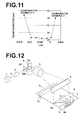
- the radiation image readout apparatus will be described with reference to Figure 12 .
- the light beam 2 enters a collimating lens 3 and is collimated thereby, then enters a mirror 4a of a galvanometer mirror 4, which is an optical deflector.
- the mirror 4a swings reciprocally within a predetermined angular range, to reflect and deflect the light beam 2 that enters thereinto.
- the light beam which is deflected in this manner passes through a scanning lens 5, is reflected downward by an elongate planar mirror 6 to enter a scanning target surface 7, and scans the scanning target surface 7 (main scanning) in the direction indicated by the arrow X.
- the scanning lens 5 is schematically illustrated as a single lens. However, the scanning lens 5 is actually constituted by five lenses. The detailed configuration of the scanning lens 5 will be described later.
- the scanning target surface 7 of the present example is a stimulable phosphor sheet which was described above.
- the stimulable phosphor sheet 7 is employed in non destructive inspection of component parts in factories, plants such as power plants and oil refineries, and further of industrial products that constitute ships, aircraft, etc.
- a radiation image of radiation such as X rays, which have passed through an inspection target, is irradiated onto the sheet 7.
- radiation energy having an intensity distribution corresponding to transmitted radiation image information of the inspection target is accumulated and recorded in the stimulable phosphor sheet 7.
- the amount of time that radiation is irradiated onto the stimulable phosphor sheet 7 can be set to approximately the same amount of time as that for a case in which the target of inspection is comparatively thin, by setting the power of the semiconductor laser 1 high during readout as described previously.
- the amount of time that radiation is irradiated onto the stimulable phosphor sheet 7 can be shortened to a greater degree, by setting the power of the semiconductor laser 1 to be high.
- the stimulable phosphor sheet 7 having the transmitted radiation image of the inspection target recorded therein is main scanned by the light beam 2, photostimulated light having intensities corresponding to accumulated radiation energy is emitted from portions of the sheet 7 which are irradiated with the light beam.
- the photostimulated light is collected by a light collecting guide 8, and photoelectrically detected by a photomultiplier 9 at each main scanning position.
- the light collecting guide 8 has a light input facet 8a that extends along a main scanning line on the stimulable phosphor sheet 7 and a light output facet 8b that outputs the photostimulated light which enters the light input facet 8a and propagates through the light collecting guide 8.
- the photomultiplier 9 is optically connected to the light output facet 8b.
- the stimulable phosphor sheet 7 is fed in a direction substantially perpendicular to the direction of the main scanning by a sub scanning means 10 constituted by nip rollers, etc. Thereby, the stimulable phosphor sheet 7 is optically scanned two dimensionally.
- the photomultiplier 9 outputs optical detection signals that represent the transmitted radiation image which was recorded in the stimulable phosphor sheet 7.
- the optical detection signals are sent to an image display device such as a liquid crystal display device and a CRT, or to an image recording means such as an optical scan recording apparatus as read out image signals, that is, provided to reproduce the radiation image.
- the galvanometer mirror 4 and the scanning lens 5 described above constitute a scanning optical system according to an embodiment of the present invention.
- the semiconductor laser 1, the collimating lens 3, and the sub scanning means 10 are added to the scanning optical system to constitute an optical scanning apparatus according to an embodiment of the present invention.
- the deflection angular range of the light beam 2 by the galvanometer mirror 4 is 40° or less, which is comparatively narrower than that of a polygon mirror or the like having a structure in which a mirror is rotated.
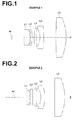
- Figure 1 is a sectional diagram that illustrates the configuration of a scanning optical system according to Example 1 of the present invention.
- Figure 2 through Figure 5 are sectional diagrams that illustrate the configurations of scanning optical systems according to other embodiments of the present invention, each of which corresponds to scanning optical systems according to Examples 2 through 5 to be described later.
- the left side is the side of a light source
- the right side is the side of a scanning target surface.
- the scanning optical system of the present embodiment is constituted by the galvanometer mirror 4 (only the mirror 4a thereof is illustrated in Figure 1 ), a first lens L1 having a positive refractive power provided adjacent to the galvanometer mirror 4 toward the side of the scanning target surface, a second lens L2 having a negative refractive power adjacent to the first lens L1 toward the side of the scanning target surface, a third lens L3 having a negative refractive power provided adjacent to the second lens L2 toward the side of the scanning target surface, a fourth lens L4 having a negative refractive power provided adjacent to the third lens L3 toward the side of the scanning target surface, and a fifth lens L5 having a positive refractive power provided adjacent to the fourth lens L4 toward the side of the scanning target surface as practical lenses.
- “having a positive refractive power” will simply be referred to as "positive”.
- having a positive refractive power will simply
- the lenses L1 through L5 are all spherical lenses, and together constitute the scanning lens 5 (refer to Figure 12 ) having f ⁇ properties.
- the "positive”, “negative”, “negative”, “negative”, and “positive” combination of refractive powers of the five lenses in this order from the light input side is common among Examples 2 through 4 and Comparative Example 1 to be described later.
- the combination of refractive powers is "positive”, “negative”, “negative”, “positive”, and “positive” in this order from the light input side.
- the present embodiment satisfies the following conditional formula: - 4.654 ⁇ f / f ⁇ 4 ⁇ 0.255 wherein f is the focal length of the entire scanning lens 5, and f4 is the focal length of the fourth lens L4.
- Table 8 shows the values of the focal length f of the entire system, the focal length f1 of the first lens L1, the focal length f2 of the second lens L2, the focal length f3 of the third lens L3, the focal length f4 of the fourth lens L4, the focal length f5 of the fifth lens L5, f1/f, f2/f, f3/f, f4/f, f5/f, 1/f4, and f/f4 (in units of millimeters) for present Example 1, Examples 2 through 5, and Comparative Examples 1 and 2 to be described later.
- conditions related to the aforementioned Conditional Formulae (1) through (6) are denoted with the numbers of the conditional formulae. Further, the minimum values and the maximum values in Examples 1 through 5 of particularly necessary conditions are indicated with darkened backgrounds in Table 8.
- the beam diameter d was derived by calculations as a full width at half maximum for a case that the wavelength of the light beam 2 is 660nm as described above.
- an aperture plate 20 is provided in the optical path of the light beam 2 which is collimated by the collimating lens 3, as illustrated in Figure 12 .
- the beam diameter d was calculated assuming that the diameter of an aperture 20a of the aperture plate 20 was 12mm.
- the angular range of deflection of the light beam 2 by the galvanometer mirror 4 is 40° ( ⁇ 20°)
- a main scanning length is 356mm
- the distance from the mirror 4a to the scanning target surface is approximately 650mm.
- the wavelength, the diameter of the aperture 20a, the range of deflection angles, the main scanning length, and the distance from the mirror 4a to the scanning target substance are common for Examples 2 through 5 and Comparative Examples 1 and 2 to be described later.
- the beam diameter d on the stimulable phosphor sheet 7 can be set to 30 ⁇ m or less if the value of f/f4 satisfies Conditional Formula (1).
- the beam diameters d are 32.4 ⁇ m and 32. 0 ⁇ m, respectively, which does not meet the demand to set the beam diameter d to be 30 ⁇ m or less.
- Table 8 also shows the focal length f of the entire lens system of the scanning lens 5.
- the focal length f is 511.9mm.
- the distance between the mirror 4a and the first lens L1 of the scanning lens 5 (the lens most toward the mirror 4a) in Example 1 is shown in Table 1, and this distance is 29.916mm.
- the distance from the mirror 4a of the galvanometer mirror 4 and the scanning target surface is approximately 650mm in the present embodiment.
- the total of the distances Di among surfaces shown in Table 1 to be described later is also 649.896mm.
- the scanning optical system of the present invention is not limited to such a configuration, and it is easy to configure the scanning optical system such that this distance is less than 650mm.
- the mirror 6 of Figure 12 is provided at a position at approximately half this distance, it is easy to set the length of the horizontal optical path from the mirror 4a to the mirror 6 and the length of the vertical optical path from the mirror 6 to the scanning target surface to be 350mm or less, respectively. Accordingly, miniaturization of the optical scanning apparatus can be realized.
- the beam diameter d can be set to 30 ⁇ m or less and that the optical scanning apparatus can be miniaturized can similarly be obtained by Examples 2 through 5 to be described later.
- the scanning optical system of the present embodiment satisfies the following conditional formula. - 0.0091 ⁇ 1 / f ⁇ 4 ⁇ 0.0005
- the relationship between values of 1/f4 and the beam diameter d is illustrated in Figure 11 .
- the beam diameter d on the scanning target surface can be set to 30 ⁇ m or less also in the case that the value of 1/f4 satisfies Conditional Formula (2).
- the beam diameter d can be set to 30 ⁇ m or less also in cases that the following conditional formulae are satisfied individually or in combinations, in addition to at least one of Conditional Formulae (1) and (2) 0.200 ⁇ f ⁇ 1 / f ⁇ 0.267 - 1.088 ⁇ f ⁇ 2 / f ⁇ - 0.321 - 0.662 ⁇ f ⁇ 3 / f ⁇ - 0.437 0.424 ⁇ f ⁇ 5 / f ⁇ 0.567
- FIG. 1 is a sectional diagram of the scanning optical system of Example 1. Note that a detailed description regarding Figure 1 has already been given. Therefore, redundant descriptions will be omitted here, unless particularly necessary.
- the scanning optical system of Example 1 is constituted by: the mirror 4a of the galvanometer mirror 4; the first lens L1, which is a positive meniscus lens; the second lens L2, which is a negative meniscus lens; the third lens L3, which is a negative meniscus lens; the fourth lens L4, which is a negative meniscus lens, and the fifth lens L5, which is a positive biconvex lens, provided in this order from the light beam input side to the scanning target surface.
- Table 1 shows basic lens data of the scanning optical system of Example 1. Note that in the following description, the sides of the elements present between the mirror 4a and the scanning target surface 7 toward the mirror 4a are referred to as the rearward sides thereof, and the sides of the elements present between the mirror 4a and the scanning target surface 7 toward the scanning target surface 7 are referred to as the frontward sides thereof.
- the radii of curvature of ith surfaces are shown in the column Ri, and the distances between an ith surface and an i+1st surface along an optical axis Z are shown in the column Di. Note that with respect to the surface having surface number 11, the i+1st surface is the scanning target surface.
- the Abbe's numbers of the jth lenses with respect to the d line are shown in the column vdj.
- Table 1 shows numerical values which are rounded to a predetermined number of digits.
- the signs of the radii of curvature are positive in cases that the surface shape is convex toward the rearward side, and negative in cases that the surface shape is convex toward the frontward side.
- the manners in which the basic data are shown are the same for Tables 2 through 7 to be described later.
- Example 1 Lens Data Wavelength: 660nm, Deflection Angle 40° ( ⁇ 20°), Aperture Diameter ⁇ : 12mm Si Ri Di Ndj ⁇ dj (Surface Number) (Radius of Curvature) (Distance) (Refractive Index) (Abbe's Number) 1 29.916 2 -905.400 14.550 1.51680 64.20 3 -50.011 1.768 4 -59.287 3.525 1.51680 64.20 5 -76.282 4.840 6 141.912 4.362 1.51680 64.20 7 77.380 9.855 8 -44.305 9.444 1.51680 64.20 9 -219.124 30.092 10 1334.387 25.127 1.51680 64.20 11 -121.12 516.417
- Figure 2 is a sectional diagram of the scanning optical system of Example 2.
- the scanning optical system of Example 2 is constituted by: the mirror 4a of the galvanometer mirror 4; a first lens L1, which is a positive meniscus lens; a second lens L2, which is a negative meniscus lens; a third lens L3, which is a negative meniscus lens; a fourth lens L4, which is a negative meniscus lens, and a fifth lens L5, which is a positive biconvex lens, provided in this order from the light beam input side to the scanning target surface.
- Table 2 shows basic lens data of the scanning optical system of Example 2.
- Example 2 Lens Data Wavelength: 660nm, Deflection Angle 40° ( ⁇ 20°), Aperture Diameter ⁇ : 12mm Si Ri Di Ndj ⁇ dj (Surface Number) (Radius of Curvature) (Distance) (Refractive Index) (Abbe's Number) 1 30.021 2 -989.196 7.108 1.51680 64.20 3 -52.536 1.702 4 -162.150 5.389 1.51680 64.20 5 -4418.170 4.792 6 265.243 3.719 1.51680 64.20 7 96.456 11.789 8 -40.035 9.299 1.51680 64.20 9 -89.803 24.504 10 3611.174 24.985 1.51680 64.20 11 -117.115 526.726
- Figure 3 is a sectional diagram of the scanning optical system of Example 3.
- the scanning optical system of Example 3 is constituted by: the mirror 4a of the galvanometer mirror 4; a first lens L1, which is a positive biconvex lens; a second lens L2, which is a negative biconcave lens; a third lens L3, which is a negative meniscus lens; a fourth lens L4, which is a negative meniscus lens, and a fifth lens L5, which is a positive biconvex lens, provided in this order from the light beam input side to the scanning target surface.
- Table 3 shows basic lens data of the scanning optical system of Example 3.
- Example 3 Lens Data Wavelength: 660nm, Deflection Angle 40° ( ⁇ 20°), Aperture Diameter ⁇ : 12mm Si Ri Di Ndj ⁇ dj (Surface Number) (Radius of Curvature) (Distance) (Refractive Index) (Abbe's Number) 1 30.001 2 293.170 19.332 1.51680 64.20 3 -83.526 1.889 4 -3170.000 5.474 1.51680 64.20 5 135.316 2.981 6 570.367 8.144 1.51680 64.20 7 111.109 13.077 8 -50.734 11.25 1.51680 64.20 9 -90.118 22.716 10 607.361 15.018 1.51680 64.20 11 -139.099 520.109
- Figure 4 is a sectional diagram of the scanning optical system of Example 4.
- the scanning optical system of Example 4 is constituted by: the mirror 4a of the galvanometer mirror 4; a first lens L1, which is a positive biconvex lens; a second lens L2, which is a negative biconcave lens; a third lens L3, which is a negative biconcave lens; a fourth lens L4, which is a negative meniscus lens, and a fifth lens L5, which is a positive biconvex lens, provided in this order from the light beam input side to the scanning target surface.
- Table 4 shows basic lens data of the scanning optical system of Example 4.
- Example 4 Lens Data Wavelength: 660nm, Deflection Angle 40° ( ⁇ 20°), Aperture Diameter ⁇ : 12mm Si Ri Di Ndj ⁇ dj (Surface Number) (Radius of Curvature) (Distance) (Refractive Index) (Abbe's Number) 1 29.955 2 204.086 11.143 1.51680 64.20 3 -97.451 1.490 4 -245.683 7.113 1.51680 64.20 5 189.913 5.819 6 -1766.299 13.407 1.51680 64.20 7 123.118 15.779 8 -59.656 16.358 1.51680 64.20 9 -79.379 8.329 10 308.371 14.946 1.51680 64.20 11 -212.744 525.712
- FIG. 5 is a sectional diagram of the scanning optical system of Example 5.
- the scanning optical system of Example 5 is constituted by: the mirror 4a of the galvanometer mirror 4; a first lens L1, which is a positive biconvex lens; a second lens L2, which is a negative meniscus lens; a third lens L3, which is a negative biconcave lens; a fourth lens L4, which is a positive meniscus lens, and a fifth lens L5, which is a positive biconvex lens, provided in this order from the light beam input side to the scanning target surface.
- Table 5 shows basic lens data of the scanning optical system of Example 5.
- Example 5 Lens Data Wavelength: 660nm, Deflection Angle 40° ( ⁇ 20°), Aperture Diameter ⁇ : 12mm Si Ri Di Ndj ⁇ dj (Surface Number) (Radius of Curvature) (Distance) (Refractive Index) (Abbe's Number) 1 30.001 2 82.134 4.999 1.51680 64.20 3 -472.071 4.998 4 323.252 4.499 1.51680 64.20 5 66.485 5.499 6 -162.567 5.000 1.51680 64.20 7 446.099 25.887 8 -104.619 7.052 1.51680 64.20 9 -97.133 20.985 10 323.989 15.001 1.51680 64.20 11 -271.084 526.078
- FIG. 6 is a sectional diagram of the scanning optical system of Comparative Example 1.
- the scanning optical system of Comparative Example 1 is constituted by: the mirror 4a of the galvanometer mirror 4; a first lens L1, which is a positive biconvex lens; a second lens L2, which is a negative meniscus lens; a third lens L3, which is a negative meniscus lens; a fourth lens L4, which is a negative biconcave lens, and a fifth lens, which is a positive biconvex lens, provided in this order from the light beam input side to the scanning target surface.
- Table 6 shows basic lens data of the scanning optical system of Comparative Example 1.
- Figure 7 is a sectional diagram of the scanning optical system of Comparative Example 2.
- the scanning optical system of Comparative Example 2 is constituted by: the mirror 4a of the galvanometer mirror 4; a first lens L1, which is a positive biconvex lens; a second lens L2, which is a negative biconcave lens; a third lens L3, which is a negative biconcave lens; a fourth lens L4, which is a positive meniscus lens, and a fifth lens, which is a positive biconvex lens, provided in this order from the light beam input side to the scanning target surface.
- Table 7 shows basic lens data of the scanning optical system of Comparative Example 2.
- the scanning optical system of the present invention is not limited to those of the above Examples, and various changes and modifications are possible.
- the radius of curvature of each lens, the distances among surfaces, the refractive indices, and the Abbe's numbers can be changed as appropriate.
- the scanning optical system of the present invention is not limited to application to the radiation image readout apparatus described above.
- the scanning optical system of the present invention may be applied to other types of readout apparatuses, and further to optical scanning recording apparatuses and the like. The same advantageous effects as those described above can be exhibited with respect to obtaining a desired scanning beam diameter.
Landscapes
- Physics & Mathematics (AREA)
- General Physics & Mathematics (AREA)
- Optics & Photonics (AREA)
- Health & Medical Sciences (AREA)
- Life Sciences & Earth Sciences (AREA)
- High Energy & Nuclear Physics (AREA)
- Molecular Biology (AREA)
- Spectroscopy & Molecular Physics (AREA)
- Lenses (AREA)
- Mechanical Optical Scanning Systems (AREA)
- Facsimile Scanning Arrangements (AREA)
Abstract
[Objective]
To obtain a scanning optical system capable of being configured to be compact and of sufficiently decreasing the beam diameter of light on a scanning target surface.
[Constitution]
A scanning optical system includes: a galvanometer mirror (illustrated as mirror 4a in the drawings) (4) that reflects and deflects a light beam (2) emitted from a light source, and an fθ lens (5) that focuses the deflected light beam (2) on a scanning target surface. The fθ lens (5) is constituted by a first lens (L1), which is a spherical lens having a positive refractive power, a second lens (L2), which is a spherical lens having a negative refractive power, a third lens (L3), which is a spherical lens having a negative refractive power, a fourth lens (L4), which is a spherical lens having one of a positive refractive power and a negative refractive power, and a fifth lens (L5), which is a spherical lens having a positive refractive power, provided in this order from the side of the galvanometer mirror (4). The scanning optical system satisfies Conditional Formula (1) below:

wherein f is the focal length of the entire fθ lens (5), and f4 is the focal length of the fourth lens (L4).
Description
- The present invention is related to an optical scanning apparatus that scans scanning target surfaces, which are recording materials or the like, with a light beam.
- The present invention is also related to a scanning optical system, which is employed in such an optical scanning apparatus, that includes an fθ lens.
- The present invention is also related to a radiation image readout apparatus that employs such an optical scanning apparatus, to read out radiation images which are recorded on stimulable phosphor sheets.
- Various conventional optical scanning apparatuses that cause light beams to enter mechanical optical deflectors, such as a galvanometer mirror having a reciprocating mirror and a polygon mirror having a rotating mirror, to reflect and deflect the light beam, and scan scanning target surfaces with the deflected light beams have been proposed. This type of optical scanning apparatus is often applied to optical scanning readout apparatuses that scan recording materials, in which information is recorded, and read out the information recorded in the recording materials by detecting light emitted by the recording material which has received irradiation of light, light transmitted through scanning target surfaces, or light reflected by scanning target surfaces. In addition, this type of optical scanning apparatus is also often applied to optical scanning recording apparatuses that write information into recording materials such as photosensitive materials that react to light, by scanning the recording materials with light which is modulated based on the information to be recorded. Generally, in optical scanning apparatuses that employ the optical deflectors described above, the deflected light beams are caused to pass through scanning lenses to focus them to have small spot diameters (referred to as "beam diameter" in the present specification), in order to maintain high precision in readout and recording. Lenses having fθ properties are commonly employed as the scanning lenses, such that the light beams are scanned at a constant speed on scanning target substances when the light beams are deflected at a constant angular speed. fθ properties are those that cause the image heights of a light beam on a scanning target surface to be proportional to deflection angles θ. Lenses having such properties are referred to as fθ lenses.
- Meanwhile, radiation image readout apparatuses that read out radiation images which are recorded on stimulable phosphor sheets are known as a type of optical scanning readout apparatus, as disclosed in Japanese Unexamined Patent Publication No.
2003-228145 2003-228145 - Radiation image recording/readout systems that employ the stimulable phosphor sheets are widely utilized not only to record and read out transmitted radiation images of human bodies in the medical/clinical fields, but are also employed in non destructive inspection of component parts in factories, plants such as power plants and oil refineries, and further in ships, aircraft, etc.
- The methods defined in ISO 17636-2 and EN (European Standards) 14784-1 are known as methods for evaluating resolution performance in industrial radiation image recording/readout systems. In these methods, it is desired for the resolution performance to be measured by two wires determined by EN 462-5, which are referred to as a duplex wire (refer to "Non Destructive Inspections", Vol. 61, No. 4, p. 146, 2012). The method for evaluating resolution performance employing the two wires records an image of the two wires arrayed next to each other on a stimulable phosphor sheet. Then, readout signals related to the arrangement direction of the wires are obtained by a readout process. Then, the percentage (%) of signal amplitude if the gap between the wires with respect to the signal intensity amplitude of the readout signals that represent the entirety of the wire portion is investigated. It is commonly said that a percentage of 20% or greater is necessary to reproduce radiation images having high resolution.
- The present inventors investigated the relationship between the resolution properties defined by the above percentage (%) and the beam diameter of excitation light in greater detail by conducting experiments. Two wires having diameters of 50µm were used, and the interval therebetween was set to 50µm. In these experiments, "UR-1", which is a high resolution type stimulable phosphor sheet (in which BaFX:Eu2+ (wherein X is Br and I) is the stimulable phosphor) produced by FUJIFILM Corporation, was employed as the stimulable phosphor sheet, the power of a laser light source that emits a readout light beam having a wavelength of 660nm was set to 2mW, the pixel size was set to 25µm·25µm, and the readout speed per pixel was set to 0.7µsec (microseconds).
Figure 8 illustrates the results of these experiments. It can be understood from the experimental results that it is necessary to set the beam diameter to 36µm or less in order to secure resolution properties of 20% or greater. - There are various types of known scanning optical systems equipped with fθ lenses. For example, Japanese Unexamined Patent Publication No.
1(1989)-309021 - Japanese Patent Publication No.
60(1985)-053294 60(1985)-053294 - Japanese Unexamined Patent Publication No.
62(1987)-262812 62(1987)-262812 - Japanese Unexamined Patent Publication No.
10(1998)-186258 - Incidentally, in inspections of components in fields related to aerospace technology, it is often the case that it is sufficient to set the power of lasers during readout to approximately 2mW as described above, because the thicknesses of the components are comparatively thin. That is, when recording radiation images of comparatively thin components, radiation such as X rays and γ rays pass favorably through the components. Therefore, the dosage of radiation irradiated onto stimulable phosphor sheets is great, and read out image signals having high S/N ratios can be obtained even if the power of the lasers is set to approximately 2mW, which is a comparatively low power.
- In contrast, in inspections in components in fields related to oil and electrical power, the dosage of radiation irradiated onto stimulable phosphor sheets when recording radiation images tends to be small, because the thicknesses of the components are comparatively thick. In such cases, setting the time during which radiation is irradiated to be longer to increase the dosage of radiation irradiated onto the stimulable phosphor sheets may be considered in order to obtain read out image signals having S/N ratios which are as high as those obtained in cases that components are thin. However, if such a measure is taken, the amount of time required to record radiation images will become long. It is effective to set the power of a laser during readout to be high to increase the intensity of stimulated light emitted by a stimulable phosphor sheet such that read out image signals having a high S/N ratio can be obtained even if the dosage of radiation irradiated onto the stimulable phosphor sheet is decreased, in order to obtain read out image signals having a high S/N ratio while maintaining the amount of time that radiation is irradiated comparatively short.
- A case in which the power of a laser during readout is increased in response to a demand to set the amount of time that radiation is irradiated to be approximately the same in cases that components, of which images are to be recorded, are thick and cases that components are thin. However, if the thicknesses of components are the same, the amount of time that radiation is irradiated can be set to be even shorter by increasing the power of a laser during readout. That is, in the case that it is sufficient for the power of a laser during to be set to 2mW if the amount of time that radiation is irradiated is 10 minutes, the amount of time that irradiation is irradiated can be shortened to two minutes and 30 seconds, which is 1/4 of 10 minutes, by setting the power of the laser during readout to be 8mW, which is four times 2mW.
- However, it is necessary for a required resolution to be secured even if the power of the laser is set high. It can be understood from
Figure 8 that in the case that a beam diameter is set to 36µm or less, higher resolution can be obtained as the beam diameter becomes finer. Therefore, the present inventors conducted experiments with conditions other than the beam diameter and the power of a laser being the same as those forFigure 8 to investigate changes in resolution according to the power of a laser in detail, by setting the power of a laser to various values while maintaining the beam diameter at 30µm. Table 9 andFigure 9 show the results of these experiments. It can be understood from the experimental results that a resolution of 20% or greater ca be secured even if the power of a laser is increased to approximately 8mW, if the beam diameter can be set to 30µm or less. - Scanning optical systems equipped with the previously described fθ lenses are in wide use in radiation image readout apparatuses that scan the aforementioned stimulable phosphor sheets. In such cases, it is desirable for the beam diameter of the scanning optical systems to be capable of being set to 30µm or less, in view of the above point.
- However, it is difficult for the scanning optical system disclosed in Japanese Unexamined Patent Publication No.
1 (1989) -309021 - Meanwhile, the length of the optical path of the entire scanning optical system disclosed in Japanese Patent Publication No.
60 (1985)-053294 - In addition, the scanning optical systems disclosed in Japanese Unexamined Patent Publication Nos.
62(1987)-262812 10 (1998)-186258 - The present invention has been developed in view of the foregoing circumstances. It is an object of the present invention to provide a scanning optical system that employs a galvanometer mirror as an optical deflector, which can be formed to be compact, and is capable of achieving a sufficiently small beam diameter on a scanning target surface, an optical scanning apparatus, and a radiation image readout apparatus.
- A scanning optical system of the present invention comprises:
- a galvanometer mirror that reflects and deflects a light beam emitted from a light source, having a deflection angle range of 40° or less; and
- an fθ lens that focuses the deflected light beam on a scanning target surface;
- the fθ lens substantially consisting of a first lens, which is a spherical lens having a positive refractive power, a second lens, which is a spherical lens having a negative refractive power, a third lens, which is a spherical lens having a negative refractive power, a fourth lens, which is a spherical lens having one of a positive refractive power and a negative refractive power, and a fifth lens, which is a spherical lens having a positive refractive power, provided in this order from the side of the galvanometer mirror; and
- the scanning optical system satisfying Conditional Formula (1) below:

wherein f is the focal length of the entire f8 lens, and f4 is the focal length of the fourth lens. - Here, the expression "substantially consisting of..." refers to cases including those in which the fθ lens also includes lenses that practically do not have any power and optical elements other than lenses such as a cover glass, in addition to the first through fifth lenses.
- Note that it is desirable for the scanning optical system of the present invention to satisfy the following conditional formula.

- Further, it is desirable for the scanning optical system of the present invention to satisfy the following conditional formula, in addition to at least one of conditional formulae (1) and (2).

wherein f1 is the focal length of the first lens. - In addition, it is desirable for the scanning optical system of the present invention to satisfy the following conditional formula, in addition to at least one of conditional formulae (1) and (2).

wherein f2 is the focal length of the second lens. - In addition, it is desirable for the scanning optical system of the present invention to satisfy the following conditional formula, in addition to at least one of conditional formulae (1) and (2).

wherein f3 is the focal length of the third lens. - Further, it is desirable for the scanning optical system of the present invention to satisfy the following conditional formula, in addition to at least one of conditional formulae (1) and (2).

wherein f5 is the focal length of the fifth lens. - It is desirable for the scanning optical system to be that which focuses the deflected light beam on a stimulable phosphor sheet as the scanning target surface.
- Meanwhile, an optical scanning apparatus according to the present invention is configured to scan a scanning target surface with a light beam via the scanning optical system of the present invention. Note that it is desirable for a stimulable phosphor sheet to be the scanning target surface which is scanned by the optical scanning apparatus according to the present invention.
- In addition, a radiation image readout apparatus according to the present invention is equipped with the optical scanning apparatus of the present invention described above, and is configured to detect stimulated light emitted from portions of a stimulable phosphor sheet scanned by the optical scanning apparatus, to read out a radiation image which is recorded in the stimulable phosphor sheet.
- In the scanning optical system of the present invention, the fθ lens is constituted by the first lens, which is a spherical lens having a positive refractive power, the second lens, which is a spherical lens having a negative refractive power, the third lens, which is a spherical lens having a negative refractive power, the fourth lens, which is a spherical lens having one of a positive refractive power and a negative refractive power, and the fifth lens, which is a spherical lens having a positive refractive power, provided in this order from the side of the galvanometer mirror. In addition, the scanning optical system satisfies Conditional Formula (1). Therefore, it becomes possible for the beam diameter on the scanning target surface to be set to the aforementioned 30µm or less. Further, the length from the galvanometer mirror to the scanning target surface can be made sufficiently short, enabling miniaturization. The above advantageous effects will be described in greater detail in connection with embodiments of the present invention.
- Note that the demand to set beam diameters to be 30µm or less on scanning target surfaces is present in apparatuses other than the aforementioned radiation image readout apparatus. The scanning optical system is capable of meeting all such demands.
- Meanwhile, the optical scanning apparatus and the radiation image readout apparatus of the present invention are those to which the scanning optical system of the present invention is applied. Therefore, the optical scanning apparatus and the radiation image readout apparatus of the present invention are capable of meeting the demand to set the beam diameter to be 30µm or less on a scanning target surface. Particularly, the radiation image readout apparatus is capable of obtaining high resolution read out images.
-
-
Figure 1 is a sectional diagram that illustrates the lens configuration of a scanning optical system according to Example 1 of the present invention. -
Figure 2 is a sectional diagram that illustrates the lens configuration of a scanning optical system according to Example 2 of the present invention. -
Figure 3 is a sectional diagram that illustrates the lens configuration of a scanning optical system according to Example 3 of the present invention. -
Figure 4 is a sectional diagram that illustrates the lens configuration of a scanning optical system according to Example 4 of the present invention. -
Figure 5 is a sectional diagram that illustrates the lens configuration of a scanning optical system according to Example 5 of the present invention. -
Figure 6 is a sectional diagram that illustrates the lens configuration of a scanning optical system according to Comparative Example 1 with respect to the scanning optical system of the present invention. -
Figure 7 is a sectional diagram that illustrates the lens configuration of a scanning optical system according to Comparative Example 2 with respect to the scanning optical system of the present invention. -
Figure 8 is a graph for explaining desired beam diameters in optical scanning apparatuses. -
Figure 9 is a graph that illustrates the relationship between the power of a laser and resolution. -
Figure 10 is a graph that illustrates the relationship between values of f/f4 and beam diameters. -
Figure 11 is a graph that illustrates the relationship between values of 1/f4 and beam diameters. -
Figure 12 is a diagram that schematically illustrates the configuration of an optical scanning apparatus according to an embodiment of the present invention. - Hereinafter, embodiments of the present invention will be described in detail with reference to the attached drawings. A scanning optical system of the present invention is applied to a radiation image readout apparatus which was described previously, for example. First, the radiation image readout apparatus will be described with reference to
Figure 12 . - A
semiconductor laser 1, which is a light source, emits alight beam 2 having a wavelength of 660nm, for example. Thelight beam 2 enters acollimating lens 3 and is collimated thereby, then enters amirror 4a of agalvanometer mirror 4, which is an optical deflector. Themirror 4a swings reciprocally within a predetermined angular range, to reflect and deflect thelight beam 2 that enters thereinto. The light beam which is deflected in this manner passes through ascanning lens 5, is reflected downward by an elongateplanar mirror 6 to enter ascanning target surface 7, and scans the scanning target surface 7 (main scanning) in the direction indicated by the arrow X. Note that inFigure 12 , thescanning lens 5 is schematically illustrated as a single lens. However, thescanning lens 5 is actually constituted by five lenses. The detailed configuration of thescanning lens 5 will be described later. - The
scanning target surface 7 of the present example is a stimulable phosphor sheet which was described above. Thestimulable phosphor sheet 7 is employed in non destructive inspection of component parts in factories, plants such as power plants and oil refineries, and further of industrial products that constitute ships, aircraft, etc. In such an inspection, a radiation image of radiation, such as X rays, which have passed through an inspection target, is irradiated onto thesheet 7. Thereby, radiation energy having an intensity distribution corresponding to transmitted radiation image information of the inspection target is accumulated and recorded in thestimulable phosphor sheet 7. - Note that even in the case that the target of inspection is comparatively thick, the amount of time that radiation is irradiated onto the
stimulable phosphor sheet 7 can be set to approximately the same amount of time as that for a case in which the target of inspection is comparatively thin, by setting the power of thesemiconductor laser 1 high during readout as described previously. In addition, in the case that the thicknesses of targets of inspection are the same, the amount of time that radiation is irradiated onto thestimulable phosphor sheet 7 can be shortened to a greater degree, by setting the power of thesemiconductor laser 1 to be high. - When the
stimulable phosphor sheet 7 having the transmitted radiation image of the inspection target recorded therein is main scanned by thelight beam 2, photostimulated light having intensities corresponding to accumulated radiation energy is emitted from portions of thesheet 7 which are irradiated with the light beam. The photostimulated light is collected by alight collecting guide 8, and photoelectrically detected by aphotomultiplier 9 at each main scanning position. Note that thelight collecting guide 8 has alight input facet 8a that extends along a main scanning line on thestimulable phosphor sheet 7 and alight output facet 8b that outputs the photostimulated light which enters thelight input facet 8a and propagates through thelight collecting guide 8. Thephotomultiplier 9 is optically connected to thelight output facet 8b. - At the same time, the
stimulable phosphor sheet 7 is fed in a direction substantially perpendicular to the direction of the main scanning by a sub scanning means 10 constituted by nip rollers, etc. Thereby, thestimulable phosphor sheet 7 is optically scanned two dimensionally. Thephotomultiplier 9 outputs optical detection signals that represent the transmitted radiation image which was recorded in thestimulable phosphor sheet 7. The optical detection signals are sent to an image display device such as a liquid crystal display device and a CRT, or to an image recording means such as an optical scan recording apparatus as read out image signals, that is, provided to reproduce the radiation image. - The
galvanometer mirror 4 and thescanning lens 5 described above constitute a scanning optical system according to an embodiment of the present invention. In addition, thesemiconductor laser 1, thecollimating lens 3, and the sub scanning means 10 are added to the scanning optical system to constitute an optical scanning apparatus according to an embodiment of the present invention. Note that the deflection angular range of thelight beam 2 by thegalvanometer mirror 4 is 40° or less, which is comparatively narrower than that of a polygon mirror or the like having a structure in which a mirror is rotated. - Next, a scanning optical system according to an embodiment of the present invention will be described with reference to
Figure 1. Figure 1 is a sectional diagram that illustrates the configuration of a scanning optical system according to Example 1 of the present invention. In addition,Figure 2 through Figure 5 are sectional diagrams that illustrate the configurations of scanning optical systems according to other embodiments of the present invention, each of which corresponds to scanning optical systems according to Examples 2 through 5 to be described later. - Note that the basic configuration of the scanning optical system of the present invention and the advantageous effects obtained thereby will be described based on the scanning optical system of Example 1. Redundant descriptions will be omitted for the examples and comparative examples to be described later.
- In
Figure 1 , the left side is the side of a light source, and the right side is the side of a scanning target surface. The scanning optical system of the present embodiment is constituted by the galvanometer mirror 4 (only themirror 4a thereof is illustrated inFigure 1 ), a first lens L1 having a positive refractive power provided adjacent to thegalvanometer mirror 4 toward the side of the scanning target surface, a second lens L2 having a negative refractive power adjacent to the first lens L1 toward the side of the scanning target surface, a third lens L3 having a negative refractive power provided adjacent to the second lens L2 toward the side of the scanning target surface, a fourth lens L4 having a negative refractive power provided adjacent to the third lens L3 toward the side of the scanning target surface, and a fifth lens L5 having a positive refractive power provided adjacent to the fourth lens L4 toward the side of the scanning target surface as practical lenses. Hereinafter, "having a positive refractive power" will simply be referred to as "positive". Similarly, "having a negative refractive power" will simply be referred to as "negative". - The lenses L1 through L5 are all spherical lenses, and together constitute the scanning lens 5 (refer to
Figure 12 ) having fθ properties. Here, the "positive", "negative", "negative", "negative", and "positive" combination of refractive powers of the five lenses in this order from the light input side is common among Examples 2 through 4 and Comparative Example 1 to be described later. In contrast, in Example 5 and Comparative Example 2, the combination of refractive powers is "positive", "negative", "negative", "positive", and "positive" in this order from the light input side. - The present embodiment satisfies the following conditional formula:

wherein f is the focal length of theentire scanning lens 5, and f4 is the focal length of the fourth lens L4. - Table 8 shows the values of the focal length f of the entire system, the focal length f1 of the first lens L1, the focal length f2 of the second lens L2, the focal length f3 of the third lens L3, the focal length f4 of the fourth lens L4, the focal length f5 of the fifth lens L5, f1/f, f2/f, f3/f, f4/f, f5/f, 1/f4, and f/f4 (in units of millimeters) for present Example 1, Examples 2 through 5, and Comparative Examples 1 and 2 to be described later. In addition, in Table 8, conditions related to the aforementioned Conditional Formulae (1) through (6) are denoted with the numbers of the conditional formulae. Further, the minimum values and the maximum values in Examples 1 through 5 of particularly necessary conditions are indicated with darkened backgrounds in Table 8.
- The beam diameter d was derived by calculations as a full width at half maximum for a case that the wavelength of the
light beam 2 is 660nm as described above. In this case, anaperture plate 20 is provided in the optical path of thelight beam 2 which is collimated by thecollimating lens 3, as illustrated inFigure 12 . The beam diameter d was calculated assuming that the diameter of anaperture 20a of theaperture plate 20 was 12mm. In addition, the angular range of deflection of thelight beam 2 by thegalvanometer mirror 4 is 40° (±20°), a main scanning length is 356mm, and the distance from themirror 4a to the scanning target surface is approximately 650mm. The wavelength, the diameter of theaperture 20a, the range of deflection angles, the main scanning length, and the distance from themirror 4a to the scanning target substance (approximately 650mm) are common for Examples 2 through 5 and Comparative Examples 1 and 2 to be described later. - The relationship between the values of f/f4 and the beam diameter d is shown for the aforementioned seven examples in
Figure 10 . As can be understood fromFigure 10 and Table 8, the beam diameter d on thestimulable phosphor sheet 7 can be set to 30µm or less if the value of f/f4 satisfies Conditional Formula (1). Thereby, it becomes possible to obtain readout image signals that represent readout images having high resolution even if the power of the laser during readout of radiation images is increased to approximately 8mW and the amount of time that radiation is irradiated is shortened. The detailed reasons for this advantageous effect have been described previously. - In Comparative Examples 1 and 2, in which the value of f/f4 is outside the range defined in Conditional Formula (1), the beam diameters d are 32.4µm and 32. 0µm, respectively, which does not meet the demand to set the beam diameter d to be 30µm or less.
- In addition, Table 8 also shows the focal length f of the entire lens system of the
scanning lens 5. In the present embodiment, the focal length f is 511.9mm. As will be described later, the distance between themirror 4a and the first lens L1 of the scanning lens 5 (the lens most toward themirror 4a) in Example 1 is shown in Table 1, and this distance is 29.916mm. As described previously, the distance from themirror 4a of thegalvanometer mirror 4 and the scanning target surface is approximately 650mm in the present embodiment. The total of the distances Di among surfaces shown in Table 1 to be described later is also 649.896mm. However, the scanning optical system of the present invention is not limited to such a configuration, and it is easy to configure the scanning optical system such that this distance is less than 650mm. Accordingly, if themirror 6 ofFigure 12 is provided at a position at approximately half this distance, it is easy to set the length of the horizontal optical path from themirror 4a to themirror 6 and the length of the vertical optical path from themirror 6 to the scanning target surface to be 350mm or less, respectively. Accordingly, miniaturization of the optical scanning apparatus can be realized. - The two advantageous effects described above, that the beam diameter d can be set to 30µm or less and that the optical scanning apparatus can be miniaturized can similarly be obtained by Examples 2 through 5 to be described later.
- In addition, the scanning optical system of the present embodiment satisfies the following conditional formula.

The relationship between values of 1/f4 and the beam diameter d is illustrated inFigure 11 . As can be understood fromFigure 11 and Table 8, the beam diameter d on the scanning target surface can be set to 30µm or less also in the case that the value of 1/f4 satisfies Conditional Formula (2). - In addition, by referring to Table 8, it can be understood that the beam diameter d can be set to 30µm or less also in cases that the following conditional formulae are satisfied individually or in combinations, in addition to at least one of Conditional Formulae (1) and (2)


- Next, specific examples of the scanning optical system of the present invention will be described. Note that the scanning optical systems of Examples 1 through 5 and Comparative Examples 1 and 2 are all constituted by five spherical lenses.
-
Figure 1 is a sectional diagram of the scanning optical system of Example 1. Note that a detailed description regardingFigure 1 has already been given. Therefore, redundant descriptions will be omitted here, unless particularly necessary. The scanning optical system of Example 1 is constituted by: themirror 4a of thegalvanometer mirror 4; the first lens L1, which is a positive meniscus lens; the second lens L2, which is a negative meniscus lens; the third lens L3, which is a negative meniscus lens; the fourth lens L4, which is a negative meniscus lens, and the fifth lens L5, which is a positive biconvex lens, provided in this order from the light beam input side to the scanning target surface. - Table 1 shows basic lens data of the scanning optical system of Example 1. Note that in the following description, the sides of the elements present between the
mirror 4a and thescanning target surface 7 toward themirror 4a are referred to as the rearward sides thereof, and the sides of the elements present between themirror 4a and thescanning target surface 7 toward thescanning target surface 7 are referred to as the frontward sides thereof. In Table 1, ith (i=1, 2, 3,...) surface numbers that sequentially increase from the rearward side to the frontward side, with the surface of themirror 4a designated as first and the rearward surface of the next constituent element present toward the frontward side designated as second, are shown in the column Si. The radii of curvature of ith surfaces are shown in the column Ri, and the distances between an ith surface and an i+1st surface along an optical axis Z are shown in the column Di. Note that with respect to the surface having surface number 11, the i+1st surface is the scanning target surface. The refractive indices of jth (j=1, 2, 3, 4, 5) lenses from the rearward side to the frontward side with respect to the d line (wavelength: 587.6nm), j being a number that increases sequentially with the lens most toward the rearward side designated as first, are shown in the column Ndj. The Abbe's numbers of the jth lenses with respect to the d line are shown in the column vdj. - Note that the units of the radii of curvature R and the distances D between adjacent surfaces are mm in Table 1. Table 1 shows numerical values which are rounded to a predetermined number of digits. The signs of the radii of curvature are positive in cases that the surface shape is convex toward the rearward side, and negative in cases that the surface shape is convex toward the frontward side. The manners in which the basic data are shown are the same for Tables 2 through 7 to be described later.
[Table 1] Example 1: Lens Data Wavelength: 660nm, Deflection Angle 40° (±20°), Aperture Diameter ϕ: 12mmSi Ri Di Ndj νdj (Surface Number) (Radius of Curvature) (Distance) (Refractive Index) (Abbe's Number) 1 29.916 2 -905.400 14.550 1.51680 64.20 3 -50.011 1.768 4 -59.287 3.525 1.51680 64.20 5 -76.282 4.840 6 141.912 4.362 1.51680 64.20 7 77.380 9.855 8 -44.305 9.444 1.51680 64.20 9 -219.124 30.092 10 1334.387 25.127 1.51680 64.20 11 -121.12 516.417 -
Figure 2 is a sectional diagram of the scanning optical system of Example 2. The scanning optical system of Example 2 is constituted by: themirror 4a of thegalvanometer mirror 4; a first lens L1, which is a positive meniscus lens; a second lens L2, which is a negative meniscus lens; a third lens L3, which is a negative meniscus lens; a fourth lens L4, which is a negative meniscus lens, and a fifth lens L5, which is a positive biconvex lens, provided in this order from the light beam input side to the scanning target surface. Table 2 shows basic lens data of the scanning optical system of Example 2.[Table 2] Example 2: Lens Data Wavelength: 660nm, Deflection Angle 40° (±20°), Aperture Diameter ϕ: 12mmSi Ri Di Ndj νdj (Surface Number) (Radius of Curvature) (Distance) (Refractive Index) (Abbe's Number) 1 30.021 2 -989.196 7.108 1.51680 64.20 3 -52.536 1.702 4 -162.150 5.389 1.51680 64.20 5 -4418.170 4.792 6 265.243 3.719 1.51680 64.20 7 96.456 11.789 8 -40.035 9.299 1.51680 64.20 9 -89.803 24.504 10 3611.174 24.985 1.51680 64.20 11 -117.115 526.726 -
Figure 3 is a sectional diagram of the scanning optical system of Example 3. The scanning optical system of Example 3 is constituted by: themirror 4a of thegalvanometer mirror 4; a first lens L1, which is a positive biconvex lens; a second lens L2, which is a negative biconcave lens; a third lens L3, which is a negative meniscus lens; a fourth lens L4, which is a negative meniscus lens, and a fifth lens L5, which is a positive biconvex lens, provided in this order from the light beam input side to the scanning target surface. Table 3 shows basic lens data of the scanning optical system of Example 3.[Table 3] Example 3: Lens Data Wavelength: 660nm, Deflection Angle 40° (±20°), Aperture Diameter ϕ: 12mmSi Ri Di Ndj νdj (Surface Number) (Radius of Curvature) (Distance) (Refractive Index) (Abbe's Number) 1 30.001 2 293.170 19.332 1.51680 64.20 3 -83.526 1.889 4 -3170.000 5.474 1.51680 64.20 5 135.316 2.981 6 570.367 8.144 1.51680 64.20 7 111.109 13.077 8 -50.734 11.25 1.51680 64.20 9 -90.118 22.716 10 607.361 15.018 1.51680 64.20 11 -139.099 520.109 -
Figure 4 is a sectional diagram of the scanning optical system of Example 4. The scanning optical system of Example 4 is constituted by: themirror 4a of thegalvanometer mirror 4; a first lens L1, which is a positive biconvex lens; a second lens L2, which is a negative biconcave lens; a third lens L3, which is a negative biconcave lens; a fourth lens L4, which is a negative meniscus lens, and a fifth lens L5, which is a positive biconvex lens, provided in this order from the light beam input side to the scanning target surface. Table 4 shows basic lens data of the scanning optical system of Example 4.[Table 4] Example 4: Lens Data Wavelength: 660nm, Deflection Angle 40° (±20°), Aperture Diameter ϕ: 12mmSi Ri Di Ndj νdj (Surface Number) (Radius of Curvature) (Distance) (Refractive Index) (Abbe's Number) 1 29.955 2 204.086 11.143 1.51680 64.20 3 -97.451 1.490 4 -245.683 7.113 1.51680 64.20 5 189.913 5.819 6 -1766.299 13.407 1.51680 64.20 7 123.118 15.779 8 -59.656 16.358 1.51680 64.20 9 -79.379 8.329 10 308.371 14.946 1.51680 64.20 11 -212.744 525.712 -
Figure 5 is a sectional diagram of the scanning optical system of Example 5. The scanning optical system of Example 5 is constituted by: themirror 4a of thegalvanometer mirror 4; a first lens L1, which is a positive biconvex lens; a second lens L2, which is a negative meniscus lens; a third lens L3, which is a negative biconcave lens; a fourth lens L4, which is a positive meniscus lens, and a fifth lens L5, which is a positive biconvex lens, provided in this order from the light beam input side to the scanning target surface. Table 5 shows basic lens data of the scanning optical system of Example 5.[Table 5] Example 5: Lens Data Wavelength: 660nm, Deflection Angle 40° (±20°), Aperture Diameter ϕ: 12mmSi Ri Di Ndj νdj (Surface Number) (Radius of Curvature) (Distance) (Refractive Index) (Abbe's Number) 1 30.001 2 82.134 4.999 1.51680 64.20 3 -472.071 4.998 4 323.252 4.499 1.51680 64.20 5 66.485 5.499 6 -162.567 5.000 1.51680 64.20 7 446.099 25.887 8 -104.619 7.052 1.51680 64.20 9 -97.133 20.985 10 323.989 15.001 1.51680 64.20 11 -271.084 526.078 -
Figure 6 is a sectional diagram of the scanning optical system of Comparative Example 1. The scanning optical system of Comparative Example 1 is constituted by: themirror 4a of thegalvanometer mirror 4; a first lens L1, which is a positive biconvex lens; a second lens L2, which is a negative meniscus lens; a third lens L3, which is a negative meniscus lens; a fourth lens L4, which is a negative biconcave lens, and a fifth lens, which is a positive biconvex lens, provided in this order from the light beam input side to the scanning target surface. Table 6 shows basic lens data of the scanning optical system of Comparative Example 1.[Table 6] Comparative Example 1: Lens Data Wavelength: 660nm, Deflection Angle 40° (±20°), Aperture Diameter ϕ: 12mmSi Ri Di Ndj νdj (Surface Number) (Radius of Curvature) (Distance) (Refractive Index) (Abbe's Number) 1 29.954 2 3437.770 9.815 1.51680 64.20 3 -49.339 0.917 4 -74.198 4.900 1.51680 64.20 5 -87.799 1.774 6 144.201 2.969 1.51680 64.20 7 92.266 10.576 8 -42.232 5.159 1.51680 64.20 9 1660.7 33.982 10 1167.754 31.384 1.51680 64.20 11 -115.155 518.519 -
Figure 7 is a sectional diagram of the scanning optical system of Comparative Example 2. The scanning optical system of Comparative Example 2 is constituted by: themirror 4a of thegalvanometer mirror 4; a first lens L1, which is a positive biconvex lens; a second lens L2, which is a negative biconcave lens; a third lens L3, which is a negative biconcave lens; a fourth lens L4, which is a positive meniscus lens, and a fifth lens, which is a positive biconvex lens, provided in this order from the light beam input side to the scanning target surface. Table 7 shows basic lens data of the scanning optical system of Comparative Example 2.[Table 7] Comparative Example 2: Lens Data Wavelength: 660nm, Deflection Angle 40° (±20°), Aperture Diameter ϕ: 12mm Si Ri Di Ndj νdj (Surface Number) (Radius of Curvature) (Distance) (Refractive Index) (Abbe's Number) 1 30.063 2 246.421 5.019 1.51680 64.20 3 -106.270 7.251 4 -203.799 3.465 1.51680 64.20 5 132.687 4.982 6 -115.197 4.997 1.51680 64.20 7 519.140 13.062 8 -793.418 16.109 1.51680 64.20 9 -164.446 10.647 10 340.929 14.993 1.51680 64.20 11 -286.576 539.43 [Table 8] Comparative Example 1 Example 1 Example 2 Example 3 Example 4 Example 5 Comparative Example 2 f 511.9 511.9 514.1 512.7 511.4 510.4 512.47 f1 94.7 102.4 107.6 128.7 129.9 136.5 145.1 f2 -1061.3 -556.7 -328.2 -262.0 -207.2 -163.8 -155.7 f3 -508.1 -338.7 -290.8 -270.0 -223.3 -231.1 -182.86 f4 -80.0 -110.0 -150.0 -250.0 -650.0 2000.0 400 f5 205.6 217.2 221.2 221.5 247.2 289.5 305.27 f1/f (3) 0.185 0.200 0.209 0.251 0.254 0.267 0.283 f2/f (4) -2.073 -1.088 -0.638 -0.511 -0.405 -0.321 -0.304 f3/f (5) -0.992 -0.662 -0.566 -0.527 -0.437 -0.453 -0.357 f4/f -0.156 -0.215 -0.292 -0.488 -1.271 3.919 0.781 f5/f (6) 0.402 0.424 0.430 0.432 0.484 0.567 0.596 1/f4 (2) -0.0125 -0.0091 -0.0067 -0.0040 -0.0015 0.0005 0.0025 f/ f4 (1) -6.398 -4.654 -3.427 -2.051 -0.787 0.255 1.281 Beam Diameter d 32.4 29.3 29.3 29.2 29.2 29.3 32.0 [Table 9] Laser Power (mW) Resolution (%) 2 23.0 4 22.5 6 21.1 8 20.2 10 18.9 20 16.4 - The present invention has been described above with reference to the embodiments and Examples thereof. However, the scanning optical system of the present invention is not limited to those of the above Examples, and various changes and modifications are possible. For example, the radius of curvature of each lens, the distances among surfaces, the refractive indices, and the Abbe's numbers can be changed as appropriate.
- In addition, the scanning optical system of the present invention is not limited to application to the radiation image readout apparatus described above. The scanning optical system of the present invention may be applied to other types of readout apparatuses, and further to optical scanning recording apparatuses and the like. The same advantageous effects as those described above can be exhibited with respect to obtaining a desired scanning beam diameter.
Claims (10)
- A scanning optical system, comprising:a galvanometer mirror (4) that reflects and deflects a light beam (2) emitted from a light source (1), having a deflection angle range of 40° or less; andan fθ lens (5) that focuses the deflected light beam (2) on a scanning target surface;the fθ lens (5) substantially consisting of a first lens (L1), which is a spherical lens having a positive refractive power, a second lens (L2), which is a spherical lens having a negative refractive power, a third lens (L3), which is a spherical lens having a negative refractive power, a fourth lens (L4), which is a spherical lens having one of a positive refractive power and a negative refractive power, and a fifth lens (L5), which is a spherical lens having a positive refractive power, provided in this order from the side of the galvanometer mirror (4); andthe scanning optical system satisfying Conditional Formula (1) below:

wherein f is the focal length of the entire fθ lens (5), and f4 is the focal length of the fourth lens (L4). - A scanning optical system as defined in Claim 1 that satisfies Conditional Formula (2) below:

- A scanning optical system as defined in either one of Claim 1 and Claim 2 that satisfies Conditional Formula (3) below:

wherein f1 is the focal length of the first lens (L1). - A scanning optical system as defined in any one of Claims 1 through 3 that satisfies Conditional Formula (4) below:

wherein f2 is the focal length of the second lens (L2). - A scanning optical system as defined in any one of Claims 1 through 4 that satisfies Conditional Formula (5) below:

wherein f3 is the focal length of the third lens (L3). - A scanning optical system as defined in any one of Claims 1 through 5 that satisfies Conditional Formula (6) below:

wherein f5 is the focal length of the fifth lens (L5). - A scanning optical system as defined in any one of Claims 1 through 6 that focuses a deflected light beam (2) on a stimulable phosphor sheet (7) as the scanning target surface.
- An optical scanning apparatus configured to scan a scanning target surface with a light beam (2) via a scanning optical system as defined in any one of Claims 1 through 7.
- An optical scanning apparatus as defined in Claim 8, wherein:the scanning target surface is a stimulable phosphor sheet (7).
- A radiation image readout apparatus, comprising an optical scanning apparatus as defined in Claim 9, and is configured to detect stimulated light emitted from portions of the stimulable phosphor sheet (7) scanned by the optical scanning apparatus, to read out a radiation image which is recorded in the stimulable phosphor sheet (7).
Applications Claiming Priority (1)
| Application Number | Priority Date | Filing Date | Title |
|---|---|---|---|
| JP2013177499A JP2015045773A (en) | 2013-08-29 | 2013-08-29 | Scanning optical system, optical scanning device, and radiation image reading apparatus |
Publications (1)
| Publication Number | Publication Date |
|---|---|
| EP2851726A1 true EP2851726A1 (en) | 2015-03-25 |
Family
ID=51421867
Family Applications (1)
| Application Number | Title | Priority Date | Filing Date |
|---|---|---|---|
| EP20140182476 Withdrawn EP2851726A1 (en) | 2013-08-29 | 2014-08-27 | Scanning optical system, optical scanning apparatus, and radiation image readout apparatus |
Country Status (3)
| Country | Link |
|---|---|
| US (1) | US20150060679A1 (en) |
| EP (1) | EP2851726A1 (en) |
| JP (1) | JP2015045773A (en) |
Families Citing this family (10)
| Publication number | Priority date | Publication date | Assignee | Title |
|---|---|---|---|---|
| CA2789262C (en) | 2005-04-28 | 2016-10-04 | Proteus Digital Health, Inc. | Pharma-informatics system |
| CN105763803A (en) * | 2016-02-29 | 2016-07-13 | 广东欧珀移动通信有限公司 | Control method, control device and electronic device |
| CN105892046B (en) * | 2016-03-24 | 2018-08-31 | 武汉华工激光工程有限责任公司 | Infrared two-dimensional scan microscope group |
| KR101901698B1 (en) * | 2016-05-11 | 2018-09-27 | 삼성전기 주식회사 | Optical Imaging System |
| DE202019100632U1 (en) * | 2019-02-04 | 2019-02-25 | Jenoptik Optical Systems Gmbh | F-Theta lens |
| CN111665610B (en) * | 2019-03-06 | 2022-08-16 | 信泰光学(深圳)有限公司 | Optical lens |
| CN110221411B (en) * | 2019-06-30 | 2021-06-22 | 瑞声光学解决方案私人有限公司 | Camera optics |
| CN110727082A (en) * | 2019-10-15 | 2020-01-24 | 合肥嘉东光学股份有限公司 | 50mm fixed-focus industrial lens |
| CN114602896B (en) * | 2022-03-15 | 2024-07-05 | 镇江长悦光电科技有限公司 | Method for modulating high-power laser cleaning energy distribution |
| CN115268028B (en) * | 2022-08-30 | 2024-11-01 | 哈尔滨工业大学 | A flat-field telecentric scanning lens |
Citations (9)
| Publication number | Priority date | Publication date | Assignee | Title |
|---|---|---|---|---|
| JPS6053294A (en) | 1984-07-23 | 1985-03-26 | 株式会社日立製作所 | Sleeve for walls of exhaust pipes, etc. |
| JPS62262812A (en) | 1986-05-09 | 1987-11-14 | Minolta Camera Co Ltd | Ftheta lens |
| US4755030A (en) * | 1985-11-08 | 1988-07-05 | Matsushita Electric Industrial Co., Ltd. | Lens for facsimile or laser printer |
| JPS63313114A (en) * | 1987-06-17 | 1988-12-21 | Copal Electron Co Ltd | Scanning optical system |
| JPH01309021A (en) | 1988-06-07 | 1989-12-13 | Fuji Photo Film Co Ltd | Light beam scanning optical system |
| JPH0493910A (en) * | 1990-08-06 | 1992-03-26 | Ricoh Opt Ind Co Ltd | Telecentric ftheta lens |
| JPH10186258A (en) | 1996-12-27 | 1998-07-14 | Asahi Optical Co Ltd | fθ lens system |
| JP2003228145A (en) | 2002-02-04 | 2003-08-15 | Fuji Photo Film Co Ltd | Radiation image reader |
| US20080144152A1 (en) * | 2006-12-15 | 2008-06-19 | Palo Alto Research Center Incorporated | Ultra-short pulse scanning optical system |
Family Cites Families (2)
| Publication number | Priority date | Publication date | Assignee | Title |
|---|---|---|---|---|
| JPH11258501A (en) * | 1998-01-09 | 1999-09-24 | Fuji Photo Optical Co Ltd | Collimator lens and optical scanning device using the same |
| JP5536995B2 (en) * | 2007-07-17 | 2014-07-02 | オリンパス株式会社 | Microscope objective lens and laser scanning microscope system |
-
2013
- 2013-08-29 JP JP2013177499A patent/JP2015045773A/en not_active Withdrawn
-
2014
- 2014-08-27 EP EP20140182476 patent/EP2851726A1/en not_active Withdrawn
- 2014-08-28 US US14/471,136 patent/US20150060679A1/en not_active Abandoned
Patent Citations (9)
| Publication number | Priority date | Publication date | Assignee | Title |
|---|---|---|---|---|
| JPS6053294A (en) | 1984-07-23 | 1985-03-26 | 株式会社日立製作所 | Sleeve for walls of exhaust pipes, etc. |
| US4755030A (en) * | 1985-11-08 | 1988-07-05 | Matsushita Electric Industrial Co., Ltd. | Lens for facsimile or laser printer |
| JPS62262812A (en) | 1986-05-09 | 1987-11-14 | Minolta Camera Co Ltd | Ftheta lens |
| JPS63313114A (en) * | 1987-06-17 | 1988-12-21 | Copal Electron Co Ltd | Scanning optical system |
| JPH01309021A (en) | 1988-06-07 | 1989-12-13 | Fuji Photo Film Co Ltd | Light beam scanning optical system |
| JPH0493910A (en) * | 1990-08-06 | 1992-03-26 | Ricoh Opt Ind Co Ltd | Telecentric ftheta lens |
| JPH10186258A (en) | 1996-12-27 | 1998-07-14 | Asahi Optical Co Ltd | fθ lens system |
| JP2003228145A (en) | 2002-02-04 | 2003-08-15 | Fuji Photo Film Co Ltd | Radiation image reader |
| US20080144152A1 (en) * | 2006-12-15 | 2008-06-19 | Palo Alto Research Center Incorporated | Ultra-short pulse scanning optical system |
Non-Patent Citations (1)
| Title |
|---|
| NON DESTRUCTIVE INSPECTIONS, vol. 61, no. 4, 2012, pages 146 |
Also Published As
| Publication number | Publication date |
|---|---|
| JP2015045773A (en) | 2015-03-12 |
| US20150060679A1 (en) | 2015-03-05 |
Similar Documents
| Publication | Publication Date | Title |
|---|---|---|
| EP2851726A1 (en) | Scanning optical system, optical scanning apparatus, and radiation image readout apparatus | |
| EP2876477A1 (en) | Scanning optical system, optical scanning apparatus, and radiation image readout apparatus | |
| EP2811329A1 (en) | Scanning optical system, optical scanning apparatus, and radiation image readout apparatus | |
| US12068013B2 (en) | Radiation image reading device | |
| EP0911665B1 (en) | Light beam scanning device | |
| US11852792B2 (en) | Sample observation device | |
| JP2014235351A5 (en) | ||
| EP2821834A1 (en) | Scanning optical system, optical scanning device and radiographic image reading apparatus | |
| JP3270560B2 (en) | Radiation image information reader | |
| WO2022266895A1 (en) | Optical detection system with anamorphic prism | |
| US11586008B2 (en) | Photographic objective | |
| JP5430112B2 (en) | Beam light emitter / receiver | |
| EP4152071A1 (en) | Optical imaging lens assembly and endoscopic optical device | |
| EP1345063B1 (en) | Imaging optical system for scanning | |
| CN117631207A (en) | A laser slow-axis collimation lens and lidar | |
| KR20130073720A (en) | Tele-centric lens system and bio detecting apparatus using the same | |
| WO2014103654A1 (en) | Light beam scanning device and radiation image reading device | |
| DE102006040812A1 (en) | Receiving device for laser scanner | |
| JPH063756A (en) | Photodetector | |
| JP2015004570A (en) | Photoacoustic objective optical system, and photoacoustic microscope | |
| US7042000B2 (en) | Radiation image read-out apparatus and stimulating light cut filter | |
| DE102006040813A1 (en) | Optical receiving device for laser scanner i.e. distance measuring laser scanner, for receiving reflected laser beams, has filter provided for filtering unwanted components in laser beams and arranged in parallel optical path before lens | |
| JPH02217838A (en) | Radiation image information reader | |
| Howell | Patents Reviews: 4,165,464; 4,164,650; 4,167,335; 4,168,427; 4,174,634; 4,178,510; 4,174,885; 4,175,365; 4,182,549; 4,183,624; 4,183,625; 4,183,626; 4,184,749; 4,183,668; 4,183,780; 4,184,700; 4,185,885; 4,185,891 | |
| EP1221631A1 (en) | High efficient light guiding means |
Legal Events
| Date | Code | Title | Description |
|---|---|---|---|
| PUAI | Public reference made under article 153(3) epc to a published international application that has entered the european phase |
Free format text: ORIGINAL CODE: 0009012 |
|
| 17P | Request for examination filed |
Effective date: 20140827 |
|
| AK | Designated contracting states |
Kind code of ref document: A1 Designated state(s): AL AT BE BG CH CY CZ DE DK EE ES FI FR GB GR HR HU IE IS IT LI LT LU LV MC MK MT NL NO PL PT RO RS SE SI SK SM TR |
|
| AX | Request for extension of the european patent |
Extension state: BA ME |
|
| STAA | Information on the status of an ep patent application or granted ep patent |
Free format text: STATUS: THE APPLICATION IS DEEMED TO BE WITHDRAWN |
|
| 18D | Application deemed to be withdrawn |
Effective date: 20150926 |