EP2851719A1 - Optical fiber unit for optical fiber sensor - Google Patents
Optical fiber unit for optical fiber sensor Download PDFInfo
- Publication number
- EP2851719A1 EP2851719A1 EP20140184377 EP14184377A EP2851719A1 EP 2851719 A1 EP2851719 A1 EP 2851719A1 EP 20140184377 EP20140184377 EP 20140184377 EP 14184377 A EP14184377 A EP 14184377A EP 2851719 A1 EP2851719 A1 EP 2851719A1
- Authority
- EP
- European Patent Office
- Prior art keywords
- optical fiber
- head
- fiber unit
- fiber cable
- unit
- Prior art date
- Legal status (The legal status is an assumption and is not a legal conclusion. Google has not performed a legal analysis and makes no representation as to the accuracy of the status listed.)
- Granted
Links
Images






Classifications
-
- G—PHYSICS
- G02—OPTICS
- G02B—OPTICAL ELEMENTS, SYSTEMS OR APPARATUS
- G02B6/00—Light guides; Structural details of arrangements comprising light guides and other optical elements, e.g. couplings
- G02B6/24—Coupling light guides
- G02B6/36—Mechanical coupling means
- G02B6/3616—Holders, macro size fixtures for mechanically holding or positioning fibres, e.g. on an optical bench
-
- G—PHYSICS
- G02—OPTICS
- G02B—OPTICAL ELEMENTS, SYSTEMS OR APPARATUS
- G02B6/00—Light guides; Structural details of arrangements comprising light guides and other optical elements, e.g. couplings
- G02B6/24—Coupling light guides
- G02B6/36—Mechanical coupling means
- G02B6/3616—Holders, macro size fixtures for mechanically holding or positioning fibres, e.g. on an optical bench
- G02B6/3624—Fibre head, e.g. fibre probe termination
-
- F—MECHANICAL ENGINEERING; LIGHTING; HEATING; WEAPONS; BLASTING
- F16—ENGINEERING ELEMENTS AND UNITS; GENERAL MEASURES FOR PRODUCING AND MAINTAINING EFFECTIVE FUNCTIONING OF MACHINES OR INSTALLATIONS; THERMAL INSULATION IN GENERAL
- F16B—DEVICES FOR FASTENING OR SECURING CONSTRUCTIONAL ELEMENTS OR MACHINE PARTS TOGETHER, e.g. NAILS, BOLTS, CIRCLIPS, CLAMPS, CLIPS OR WEDGES; JOINTS OR JOINTING
- F16B35/00—Screw-bolts; Stay-bolts; Screw-threaded studs; Screws; Set screws
- F16B35/04—Screw-bolts; Stay-bolts; Screw-threaded studs; Screws; Set screws with specially-shaped head or shaft in order to fix the bolt on or in an object
- F16B35/041—Specially-shaped shafts
-
- F—MECHANICAL ENGINEERING; LIGHTING; HEATING; WEAPONS; BLASTING
- F16—ENGINEERING ELEMENTS AND UNITS; GENERAL MEASURES FOR PRODUCING AND MAINTAINING EFFECTIVE FUNCTIONING OF MACHINES OR INSTALLATIONS; THERMAL INSULATION IN GENERAL
- F16B—DEVICES FOR FASTENING OR SECURING CONSTRUCTIONAL ELEMENTS OR MACHINE PARTS TOGETHER, e.g. NAILS, BOLTS, CIRCLIPS, CLAMPS, CLIPS OR WEDGES; JOINTS OR JOINTING
- F16B35/00—Screw-bolts; Stay-bolts; Screw-threaded studs; Screws; Set screws
- F16B35/04—Screw-bolts; Stay-bolts; Screw-threaded studs; Screws; Set screws with specially-shaped head or shaft in order to fix the bolt on or in an object
- F16B35/06—Specially-shaped heads
-
- G—PHYSICS
- G02—OPTICS
- G02B—OPTICAL ELEMENTS, SYSTEMS OR APPARATUS
- G02B6/00—Light guides; Structural details of arrangements comprising light guides and other optical elements, e.g. couplings
- G02B6/44—Mechanical structures for providing tensile strength and external protection for fibres, e.g. optical transmission cables
- G02B6/4401—Optical cables
- G02B6/4429—Means specially adapted for strengthening or protecting the cables
Definitions
- the present invention relates to an optical fiber unit for an optical fiber sensor.
- Patent Literature 1 describes an optical fiber unit 10.
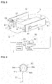
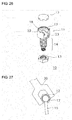
- Fig. 25 is a perspective view of the optical fiber unit 10 described in Patent Literature 1.
- Fig. 26 is a perspective exploded view of the optical fiber unit 10.
- the optical fiber unit 10 described in Patent Literature 1 includes a head 11, a cover 12, and a nut 13.
- the head 11 includes a cylindrical portion 14 and an optical fiber holder 17.
- the cylindrical portion 14 includes a through-hole 18, in which an optical fiber cable 15 is inserted.
- the optical fiber holder 17 includes a groove 22, which communicates with the through-hole 18.
- the optical fiber holder 17 is shaped in a hexagonal prism defining the groove 22.
- the optical fiber holder 17 has an opening 23 in one side of its periphery.
- the optical fiber cable 15 is inserted in the through-hole 18 of the cylindrical portion 14 and in the groove 22 of the optical fiber holder 17, bent at a predetermined curvature and then extends from the opening 23.
- Patent Literature 1 Japanese Unexamined Patent Application Publication No. 2005-156455
- the optical fiber cable 15 extends from the opening 23 formed in one side of the hexagonal prism.
- the optical fiber cable 15 extends in a direction that is not parallel to the sides on which a jig 30, such as a spanner, is set.
- the jig 30, such as a spanner, set on the optical fiber holder 17 can come in contact with the optical fiber cable 15 and damage the optical fiber cable 15. If such contact with the optical fiber cable 15 is to be avoided, the jig 30 cannot be completely engaged with the optical fiber holder 17.
- Fig. 27 is a schematic view showing the jig 30 set on the optical fiber holder 17. If the jig 30 set in the state shown in Fig.
- the jig 30 can come in contact with the optical fiber cable 15 and damage the optical fiber cable 15. If such contact with the optical fiber cable 15 is avoided in the manner shown in Fig. 27 , the jig 30 would be set incompletely on the optical fiber holder 17, disabling secure grasping of the optical fiber holder 17 with the jig.
- An optical fiber unit for an optical fiber sensor includes an optical fiber cable, a shaft, and a head.
- the shaft includes a peripheral surface having a male thread, and a through-hole in which the optical fiber cable is inserted.
- the head is shaped in a hexagonal prism and including six sides and a bottom.
- the shaft is connected to the bottom of the head.
- the optical fiber cable extends inside the head, and extends out of the head in a direction substantially parallel to two parallel sides of the six sides from at least one of the six sides other than the two parallel sides.
- the above structure allows the optical fiber cable to extend substantially parallel to two parallel sides of the six sides of the head. Even when a jig, such as a spanner, is pushed in deeply along the two parallel sides, the tip of the jig is less likely to come in contact with the optical fiber cable. This structure thus prevents damage to the optical fiber cable, which can occur when the jig is set. As a result, the jig can be pushed in to engage with the head at its deep position, enabling secure grasping of the optical fiber unit for an optical fiber sensor with the jig.
- the optical fiber cable extends from a first side that is one of the six sides other than the two parallel sides and a second side that is adjacent to the first side and is another one of the six sides other than the two parallel sidesby extending through a corner formed between the first side and the second side.
- This structure allows the optical fiber cable to extend through the through-hole of the shaft, and extends from the corner between the first side and the second side of the head.
- the direction from the through-hole of the shaft to the corner between the first side and the second side is substantially parallel to the two parallel sides.
- the optical fiber cable which extends through the corner between the first side and the second side of the head, extends in the direction substantially parallel to the two parallel sides.
- the tip of the jig is prevented from coming in contact with the optical fiber cable and thus from damaging the optical fiber cable.
- the jig can be pushed in to engage with the head at its deep position, enabling secure grasping of the optical fiber unit for an optical fiber sensor with the jig.
- the head includes a space through which the optical fiber cable is inserted, and the space communicates with the through-hole.
- the space is exposed at an opening formed across the corner.
- the opening may be defined by the remaining edges of the sides of the head.
- This structure allows the optical fiber cable to extend through the through-hole of the shaft, be bent and extend in the space, and extend from the opening.
- the opening is formed across the corner between the first side and the second side of the head.
- the space is exposed at this opening.
- the optical fiber cable extends through or around the corner between the first side and the second side and extends from the opening.
- the optical fiber cable extends in the direction substantially parallel to the two parallel sides.
- this structure enables secure grasping of the head with the jig while avoiding damage to the optical fiber cable.
- the optical fiber cable includes a single cable. This structure enables secure grasping of the head with the jig in a transmissive optical fiber sensor, while avoiding damage to the optical fiber cable in the same manner as described above.
- the optical fiber cable includes a first cable and a second cable. This structure enables secure grasping of the head with the jig in a reflective optical fiber sensor, while avoiding damage to the optical fiber cable in the same manner as described above.
- the present invention provides an optical fiber unit for an optical fiber sensor that enables secure grasping of the optical fiber unit with a jig while avoiding damage to an optical fiber cable.
- optical fiber unit 50 for a transmissive optical fiber sensor will be described first.
- Fig. 1 is a perspective view showing the appearance of an optical fiber unit 50 according to a first embodiment used for a transmissive optical fiber sensor.
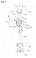
- Fig. 2 is an exploded perspective view of the optical fiber unit 50.
- Fig. 3 is an enlarged bottom view of the optical fiber unit 50.
- Fig. 4 is a cross-sectional view taken on line A-A in Fig. 3 .
- the optical fiber unit 50 includes a cover 51, an installation member 52, a lens member 55, a washer 60, a nut 61, and an optical fiber cable 57.
- the cover 51 is on the upper side of the optical fiber unit 50
- the nut 61 is on the lower side of the optical fiber unit 50 as shown in Figs. 1 to 2 and similar figures.
- the direction orthogonal to the longitudinal direction of the optical fiber unit 50 is referred to as a planar direction.
- the installation member 52 and the nut 61 are made of metal. To maintain a predetermined strength, the installation member 52 and the nut 61 in one example are formed by zinc die casting and are plated with chromium. The installation member 52 is used to install the optical fiber cable 57 onto, for example, a manufacturing line (described later).
- the installation member 52 includes a shaft 54 and a head 53.
- the shaft 54 has an internal through-hole 65, which is formed through the shaft 54 in its longitudinal direction. As described below, the optical fiber cable 57 and the lens member 55 are inserted in the through-hole 65.
- the optical fiber cable 57 is bent at a predetermined curvature as shown in Fig. 2 and is inserted in the through-hole 65.
- the shaft 54 has a male thread 54a formed on a portion of its peripheral surface. As shown in Fig. 2 , the peripheral surface of the shaft 54 includes a flat portion without the male thread 54a. However, the outer shape of the shaft 54 is not limited to this shape. The shaft 54 may be entirely cylindrical and may include the male thread 54a across its entire circumference.
- the head 53 is arranged on top of the shaft 54.
- the head 53 is integral with the shaft 54. Alternatively, the head 53 may be separate from the shaft 54.
- the head 53 has a greater outer diameter than the shaft 54, and is shaped in a substantially hexagonal prism. In the present embodiment, the head 53 is shaped in a regular hexagonal prism.
- the head 53 includes a bottom 62 and an outer wall 64.
- the bottom 62 comes in contact with the shaft 54.
- the bottom 62 is shaped in a substantially hexagonal plate.
- the outer wall 64 protrudes upward from the bottom 62.
- the bottom 62 and the outer wall 64 define a space 68.
- the space 68 extends radially outwardly from the through-hole 65 of the shaft 54.
- the space 68 communicates with the through-hole 65 of the shaft 54.
- a communicating portion between the through-hole 65 of the shaft 54 and the space 68 includes a tapered portion 62a, which results from forming a tapered end of the through-hole 65.
- the bottom 62 includes the tapered portion 62a, which communicates with the through-hole 65 of the shaft 54.
- the tapered portion 62a provides communication between the space 68 and the through-hole 65, and allows the optical fiber cable 57 to be inserted in the through-hole 65 from above the shaft 54.
- This structure further allows the optical fiber cable 57 to fix at the through-hole 65 along the curvature of the optical fiber cable 57, allowing more flexibility of the optical fiber cable 57 in the planar direction than the structure without the tapered portion 62a.
- the space 68 is larger, or specifically wider than the through-hole 65 at positions more away from the through-hole 65, allowing the optical fiber cable 57 extending from the space 68 though an opening 69 (not shown) to move within a wider area.
- the head 53 includes a plurality of sides. In the present embodiment, the head 53 is shaped in a hexagonal prism. Thus, the head 53 has six sides.
- Fig. 5 is a plan view of the installation member 52. More specifically, as shown in Fig. 5 , the head 53 includes a first side 64a, a second side 64b, a third side 64d, a fourth side 64c, a fifth side 64e, and a sixth side 64f.
- the second side 64b is adjacent to the first side 64a on one end of the first side 64a.
- the third side 64d is adjacent to the first side 64a on the other end of the first side 64a.
- the fourth side 64c is adjacent to the second side 64b.
- first side 64a is between and is adjacent to the second side 64b and the third side 64d.
- the second side 64b is between and is adjacent to the first side 64a and the fourth side 64c.
- the fourth side 64c is parallel to the third side 64d.
- the fifth side 64e is parallel to the fourth side 64c.
- the fifth side 64e is parallel to the first side 64a.
- the sixth side 64f is adjacent to the fifth side 64e.
- the sixth side 64f is parallel to the second side 64b.
- the outer wall 64 has an opening 69.
- the opening 69 includes a first opening 69a formed in the first side 64a, and a second opening 69b formed in the second side 64b.
- the first opening 69a and the second opening 69b communicate with each other.
- the opening 69 has a width D3 greater than a width Da of the first side 64a.
- the width D3 of the opening 69 is greater than a width Db of the second side 64b.
- the first opening 69a has a width D1 greater than or equal to the diameter of the optical fiber cable 57.
- the second opening 69a has a width D2 greater than or equal to the diameter of the optical fiber cable 57.
- the width D1 of the first opening 69a is equal to the width D2 of the second opening 69a.
- the width D1 of the first opening 69a may differ from the width D2 of the second opening 69a.
- the space 68 defined by the outer wall 64 communicates with the through-hole 65 of the shaft 54, with the tapered portion 62a between the space 68 and the through-hole 65.
- An attachment wall 67 which protrudes radially inward, is arranged on the inner surface of the outer wall 64.
- the upper surface of the attachment wall 67 is located lower than the upper surface of the outer wall 64 by the distance corresponding to the thickness of the cover 51.
- the cover 51 is placed on the attachment wall 67.
- the cover 51 is attached to the top of the head 53.
- the cover 51 is a lid for closing the space 68 of the head 53 in the axial direction of the through-hole 65 of the shaft 54.
- the cover 51 is set to close the space 68 from above.
- the optical fiber cable 57 is bent in a direction from the through-hole 65 of the shaft 54 toward the opening 69 of the space 68.
- the cover 51 allows this bent optical fiber cable 57 to be accommodated in the space 68 in an appropriate manner.
- the cover 51 includes a flat plate 51a and a guide 51b.
- the flat plate 51a is a plate member.
- the outer shape of the flat plate 51a includes an arc portion 51a-11, joining portions 51a-2, a first side 51c, and a second side 51d.
- the first side 51c and the second side 51d correspond to the opening 69 of the head 53, and are two straight sides adjacent to each other.
- the first side 51c and the second side 51 d are in conformance with the hexagonal sides of the bottom 62 of the head 53. More specifically, when the cover 51 is placed on the attachment wall 67, the first side 51c and the second side 51d correspond to the sides of the hexagonal bottom 62.
- first side 51c is flush with the first side 64a
- second side 51 d is flush with the second side 64b as viewed from above.
- first side 51c and the second side 51d are substantially parallel to two of the sides of the hexagonal bottom 62 corresponding to the opening 69.
- the arc portion 51a-1 is sized in conformance with the opening formed in the upper surface of the outer wall 64.
- the joining portions 51a-2 join the arc portion 51a-1 with the first side 51c and with the second side 51d.
- the guide 51b protrudes downward in a direction orthogonal to the flat plate 51a, and is shaped to engage with the attachment wall 67 of the head 53.
- the attachment wall 67 includes a guide groove 67a.
- the lens member 55 is a cylindrical lens.
- the lens member 55 is inserted in the through-hole 65 of the shaft 54, and is fixed to the tip of the optical fiber cable 57.
- the lens member 55 can focus light from the optical fiber cable 57.
- the lens member 55 is not an essential component, and can be replaced by an elongated portion of an optical fiber of the optical fiber cable 57.
- the nut 61 has a female thread, which is screwed with the male thread of the shaft 54.
- the male thread of the shaft 54 and the female thread of the nut 61 are screwed together to fix the optical fiber unit 50.
- the washer 60 is arranged between the nut 61 and the head 53. The washer 60 may be eliminated.
- the optical fiber cable 57 extends through the corner between the first side 64a and the second side 64b.
- the optical fiber cable 57 extending from the corner extends parallel to the third side 64d and the fourth side 64c.
- the opening 69 of the head 53 includes the first opening 69a in the first side 64a, and the second opening 69b in the second side 64b.
- the opening 69 is formed across the corner between the first side 64a and the second side 64b.
- the space 68 is exposed at the opening 69. More specifically, the space 68 is exposed across the corner between the first side 64a and the second side 64b. In this manner, the space 68 exposed at the opening 69 allows the optical fiber cable 57 to extend parallel to the third side 64d and the fourth side 64c.
- the optical fiber cable 57 may not extend completely parallel to the third side 64d and the fourth side 64c but may extend in a slightly deviating direction.
- the optical fiber cable 57 may extend in the manner shown in Fig. 7 .
- the optical fiber cable 57 has a central axis 58 within the range of about ⁇ 10° relative to a central axis 59 that is aligned with the center of the head 53 and is parallel to the third side 64d and the fourth side 64c.
- the optical fiber cable 57 is coated with a coating material, such as polyester. Of the two distal ends of the optical fiber cable 57, one distal end to be placed into the optical fiber unit 50 is uncovered by removing the coating material.
- the optical fiber cable 57 is bent at a predetermined curvature. Adhesive is then applied to or filled in the optical fiber cable 57 and/or the through-hole 65 to fix the optical fiber cable 57 at the through-hole 65 of the shaft 54. As a result, the optical fiber cable 57 extends parallel to the third side 64d and the fourth side 64c as described above.
- the cover 51 is attached to the head 53 to cover the upper portion of the head 53.
- the first side 51c and the second side 51d of the cover 51 are located to correspond to the sides of the hexagonal bottom 62. More specifically, the first side 51c is flush with the first side 64a.
- the second side 51d is flush with the second side 64b.
- This structure enables easy and secure grasping of the first side 51c and the fifth side 64e of the head 53 with the jig 80, such as a spanner, when the optical fiber unit 50 is installed.
- this structure also enables easy and secure grasping of the second side 51 d and the sixth side 64f of the head 53.
- the first side 64a having the first opening 69a or the second side 64b having the second opening 69b can be grasped with the jig 80.
- the L-shape joining portion 51a-2 of the cover 51 is engaged with the outer wall 64 to increase the strength of the structure when the jig 80 is set on the first side 51c or the second side 51 d of the cover 51.
- the lens member 55 is placed in the through-hole 65 of the shaft 54 from below, and is fixed in contact with the tip of the optical fiber cable 57. This completes the assembling processes of the optical fiber unit 50.
- the assembling procedure described above is a mere example.
- the assembling procedure should not be limited to the procedure described above.
- the lens member 55 may be inserted in the through-hole 65 before the optical fiber cable 57 is fixed at the through-hole 65.
- the optical fiber cable 57 may be bent after fixed at the through-hole 65.
- the head 53 without the lens member 55 eliminates the need for the process of inserting the lens member 55 in the through-hole 65.
- the optical fiber included in the optical fiber cable 57 is uncovered at positions lower than where the coating material has been removed. The uncovered portion of the optical fiber extends in the through-hole 63.
- Fig. 8 is a diagram describing the procedure for installing the optical fiber unit 50.
- the optical fiber unit 50 is installed on, for example, a manufacturing line L, on which a workpiece W is transported on a conveyer V
- the manufacturing line L includes a side wall H1 and a side wall H2.
- a pair of optical fiber units 50 for projecting light and for receiving light is installed. Openings are formed in the side walls H1 and H2 at positions where the optical fiber units 50 for projecting light and receiving light are to be installed.
- the shaft 54 of each of the optical fiber units 50 for projecting light and receiving light is inserted in the corresponding opening.
- the nut 61 is then screwed with the male thread 54a of the shaft 54.
- the optical fiber cable 57 extends through the corner between the first opening 69a and the second opening 69b and extends parallel to the third side 64d and the fourth side 64c.
- this structure thus enables secure grasping of the optical fiber unit 50 with the jig 80 while avoiding damage to the optical fiber cable 57.
- the optical fiber units 50 for projecting light and for receiving light are fixed to the corresponding side walls H1 and H2 as shown in Fig. 8 .
- the optical fiber cable 57 is set along the side wall H1 and the side wall H2.
- the optical fiber cable 57 extending from the optical fiber unit 50 is connected to the optical sensor unit 90.
- the optical sensor unit 90 includes a light projector 92 incorporating a light emitting element, a light receiver 93 incorporating a light receiving element, a controller 91, and a display 94.
- the controller 91 includes various circuits for centrally controlling the optical sensor unit 90.
- the display 94 displays the detected status of the workpiece W and also displays the settings.
- the light projecting optical fiber unit 50 which is fixed to the side wall H1, is connected to the light projector 92.
- the light receiving optical fiber unit 50 which is fixed to the side wall H2, is connected to the light receiver 93.
- the optical fiber unit 50 is installed to complete the optical fiber sensor S1 including the optical fiber unit 50 and the optical sensor unit 90.
- the optical fiber sensor S1 detects the status of the workpiece W being transported in accordance with the movement of the conveyer V
- Fig. 9 is a schematic view of the optical fiber cable 57 that extends in a modified manner. As shown in Fig. 9 , the optical fiber cable 57 extends from the first side 64a in a direction parallel to the third side 64d and the fourth side 64c. In Fig. 9 , the optical fiber cable 57 extends from the first side 64a. Alternatively, the optical fiber cable 57 may extend from the second side 64b in the direction parallel to the third side 64d and the fourth side 64c.
- the opening 69 may have a shape different from the shape described in the first embodiment.
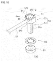
- Fig. 10 is a perspective view showing the appearance of an optical fiber unit 150 according to a modification.
- the opening 69 of the optical fiber unit 150 has a width smaller than the width of the first side 64a or the width of the second side 64b.
- the opening 69 of the optical fiber unit 150 has a width substantially equal to the diameter of the optical fiber cable 57.
- the other components of the optical fiber unit 150 are the same as the corresponding components of the optical fiber unit 50 in the first embodiment described above, and will not be described.
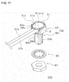
- Fig. 11 is a perspective view showing the appearance of the optical fiber unit 250 for a reflective optical fiber sensor according to a second embodiment.
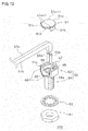
- Fig. 12 is an exploded perspective view of the optical fiber unit 250.
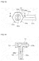
- Fig. 13 is an enlarged bottom view of the optical fiber unit 250.
- Fig. 14 is a cross-sectional view taken on line B-B in Fig. 13 .
- Fig. 15 is a plan view of the optical fiber unit 250 from which the cover 51 has been removed.
- the reflective optical fiber unit 250 according to the second embodiment differs from the transmissive optical fiber unit 50 according to the first embodiment in that it includes two optical fiber cables 57a and 57b and two lens members 55a and 55b.
- the reflective optical fiber unit 250 includes a cover 51, a head 53, a shaft 54, a washer 60, and a nut 61 that are all larger than the corresponding components of the optical fiber unit 50 of the first embodiment.
- the other components are substantially the same as described in the first embodiment, and the components that are the same as the components of the transmissive optical fiber unit 50 in the first embodiment will be described briefly or will not be described.
- the reflective optical fiber unit 250 includes the two optical fiber cables 57a and 57b, one of which is intended for projecting light, and the other is for receiving light.
- Each of the optical fiber cables 57a and 57b is the same as the optical fiber cable 57 described in the first embodiment.
- the optical fiber unit 250 includes the cover 51, the head 53, the shaft 54, the lens members 55, and the nut 61.
- the two lens members 55a and 55b are respectively arranged in correspondence with the two optical fiber cables 57a and 57b.
- the lens members 55a and 55b are fixed in correspondence with the two optical fiber cables 57a and 57b.
- the shaft 54 has a through-hole 65, which extends through the shaft 54 in its longitudinal direction.
- the through-hole 65 is sized to accommodate the two optical fiber cables 57a and 57b, which are inserted through the through-hole.
- the through-hole 65 includes a first through-hole 65a and a second through-hole 65b.
- the first through-hole 65a receives the optical fiber cable 57a.
- the second through-hole 65b receives the optical fiber cable 57b.
- the two optical fiber cables 57a and 57b are arranged adjacent to each other in the planar direction and are bound together.
- the optical fiber cable 57a and the optical fiber cable 57b separate in the vicinity of the through-hole 65.
- the first through-hole 65a and the second through-hole 65b may be separate from each other or may communicate with each other.
- the head 53 which is arranged on top of the shaft 54, includes a bottom 62 and an outer wall 64.
- the bottom 62 and the outer wall 64 define a space 68.
- the space 68 has a circular portion having a diameter large enough to allow the two optical fiber cables 57a and 57b to be inserted through it.
- the space 68 communicates with the through-hole 65 of the shaft 54.
- the through-hole 65 may include a tapered portion 62a, which results from forming a tapered end of the through-hole 65 in the communicating portion between the through-hole 65 of the shaft 54 and the space 68.
- the outer wall 64 may be eliminated from two adjacent sides of the hexagonal bottom 62, and instead an opening 69 may be formed in the adjacent sides. More specifically, the opening 69 includes a first opening 69a and a second opening 69b, which are adjacent to each other. The first opening 69a is formed in the first side 64a. The second opening 69b is formed in the second side 64b.
- An attachment wall 67 which protrudes radially inward, is arranged on the inner surface of the outer wall 64.
- the upper surface of the attachment wall 67 is located lower than the upper surface of the outer wall 64 by the distance corresponding to the thickness of the cover 51.
- the attachment wall 67 shown in Fig. 12 is arranged across the entire circumference of the outer wall 64.
- the cover 51 is attached to the top of the head 53.
- the cover 51 includes a flat plate 51a and a guide 51b.
- the outer shape of the flat plate 51a includes an arc portion 51a-1, joining portions 51a-2, a first side 51c, and a second side 51 d.
- the first side 51c and the second side 51 d correspond to the opening 69 of the head 53, and are two straight sides adjacent to each other.
- the two optical fiber cables 57a and 57b have the corresponding lens members 55a and 55b.
- the lens member 55a is fixed to the tip of the optical fiber cable 57a.
- the lens member 55b is fixed to the tip of the optical fiber cable 57b.
- the nut 61 is screwed with the male thread of the shaft 54 to fix the optical fiber unit 250.
- the washer 60 is arranged between the nut 61 and the head 53. The washer 60 may be eliminated.
- Fig. 16 is a schematic view showing the relationship between the optical fiber cables and the jig.
- the optical fiber cables 57a and 57b extend through the corner between the first side 64a and the second side 64b.
- the optical fiber cables 57a and 57b extending from the corner extend parallel to the third side 64d and the fourth side 64c.
- optical fiber cables 57a and 57b extend parallel to the third side 64d and the fourth side 64c, and thus are prevented from coming in contact with the jig 80, such as a spanner, in the same manner as described in the first embodiment.
- this structure enables secure grasping of the optical fiber unit 50 with the jig 80 while avoiding damage to the optical fiber cables 57a and 57b.
- the optical fiber cables 57a and 57b may not extend completely parallel to the third side 64d and the fourth side 64c but may extend in a slightly deviating direction.
- the optical fiber cables 57 have a central axis 58 within the range of about ⁇ 10° relative to a central axis 59 aligned with the center of the head 53 and parallel to the third side 64d and the fourth side 64c.
- a method for assembling the optical fiber cable 57a and 57b will now be described with reference to Fig. 12 .
- the method is substantially the same as the assembling method of the first embodiment described with reference to Fig. 2 , and will be described briefly.
- each of the optical fiber cables 57a and 57b one distal end of each optical fiber cable to be placed into the optical fiber unit 250 is uncovered by removing the coating material.
- the optical fiber cables 57a and 57b are bent at a predetermined curvature. Adhesive is then applied to or filled in the optical fiber cables 57a and 57b and/or the through-hole 65 to fix the optical fiber cables 57a and 57b at the through-hole 65 of the shaft 54. As a result, the optical fiber cables 57a and 57b extend parallel to the third side 64d and the fourth side 64c as described above.
- the guide 51b of the cover 51 is placed along the attachment wall 67 of the head 53. As a result, the cover 51 is attached to the head 53.
- the lens members 55a and 55b are placed into the through-hole 65 of the shaft 54, and are fixed in contact with the tips of the corresponding optical fiber cable 57a, 57b. This completes the assembling processes of the optical fiber unit 250.
- Fig. 17 is a diagram describing the procedure for installing the optical fiber unit 250.
- the optical fiber unit 250 is installed on, for example, a manufacturing line L on which a workpiece W is transported on a conveyer V
- the manufacturing line L includes a side wall H1 and a side wall H2.
- An opening is formed at a predetermined position where the optical fiber unit 250 is to be installed.
- the shaft 54 of the optical fiber unit 250 is inserted in the opening.
- the nut 61 is then screwed with the male thread 54a of the shaft 54.
- the optical fiber cables 57a and 57b extend through the corner between the first opening 69a and the second opening 69b and extend parallel to the third side 64d and the fourth side 64c.
- the head 53 is pushed in deeply against the jig 80 in the screwing process and the third side 64d and the fourth side 64c are grasped with the jig 80, the jig 80 does not come in contact with the optical fiber cable 57a and 57b.
- this structure enables secure grasping of the optical fiber unit 50 with the jig 80 while avoiding damage to the optical fiber cables 57a and 57b.
- the reflective optical fiber unit 250 is fixed to the side wall H1 as shown in Fig. 17 .
- the optical fiber cables 57a and 57b extending from the optical fiber unit 250 are fixed to the optical sensor unit 90.
- the optical fiber cable 57a for projecting light is connected to the light projector 92.
- the optical fiber cable 57b for receiving light is connected to the light receiver 93.
- the optical fiber unit 250 is installed to complete the optical fiber sensor S2 including the optical fiber unit 250 and the optical sensor unit 90.
- the optical fiber sensor S2 detects the status of the workpiece W being transported in accordance with the movement of the conveyer V
- the optical fiber cable 57 may extend in a manner different from the above-described manner.
- Fig. 18 is a schematic view of the optical fiber cables 57a and 57b that extend in a manner according to a first modification. As shown in Fig. 18 , the optical fiber cables 57a and 57b extend from the first side 64a in a direction parallel to the third side 64d and the fourth side 64c. Although the optical fiber cables 57a and 57b extend from the first side 64a in Fig. 18 , the optical fiber cables 57a and 57b may extend from the second side 64b in a direction parallel to the third side 64d and the fourth side 64c.
- the optical fiber cable 57a extends from the first side 64a in a direction parallel to the third side 64d and the fourth side 64c.
- the optical fiber cable 57b extends from the second side 64b in a direction parallel to the third side 64d and the fourth side 64c.
- the optical fiber cable 57a and the optical fiber cable 57b are separate from each other. None of the optical fiber cable 57a or the optical fiber cable 57b passes through the corner between the first side 64a and the second side 64b.
- the optical fiber cables 57a and 57b extend parallel to the third side 64d and the fourth side 64c.
- this structure prevents the optical fiber cables 57a and 57b from coming in contact with the jig 80, such as a spanner.
- this structure enables secure grasping of the optical fiber unit 50 with the jig 80 while avoiding damage to the optical fiber cables 57a and 57b.
- the invention is applicable to other optical fiber sensors including a coaxial reflective optical fiber sensor and a diffusive-reflective optical fiber sensor.
- the optical fiber units 350 and 450 used for such optical fiber sensors will now be described briefly.
- a coaxial reflective optical fiber unit 350 according to a first modification will now be described.
- the coaxial reflective optical fiber unit 350 according to a first modification of the second embodiment differs from the reflective optical fiber unit 250 according to the second embodiment in the components described below.
- the other components that are the same as in the second embodiment will not be described.
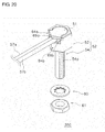
- Fig. 20 is a perspective view showing the appearance of the coaxial reflective optical fiber unit 350.
- Fig. 21 is an exploded perspective view of the optical fiber unit 350.
- the distal end of each of the optical fiber cables 57a and 57b is uncovered by removing the coating material, and thus the optical fiber 70 is exposed.
- the optical fiber 70 includes an optical fiber for projecting light and an optical fiber for receiving light that are integrated together.
- the optical fiber 70 may include the optical fiber for projecting light arranged at the center, which is surrounded by the optical fiber for receiving light.
- the optical fiber 70 uncovered by removing the coating material is inserted in the through-hole 65 of the shaft 54.
- the shaft 54 has a smaller diameter than the shaft 54 of the optical fiber unit 250 described in the second embodiment.
- the portion of the through-hole 65 for receiving the distal ends of the optical fiber cables 57a and 57b coated with the coating material is sized in conformance with the optical fiber cables 57a and 57b.
- the optical fiber 70 of the optical fiber unit 350 is inserted through the through-hole 65.
- the optical fiber unit 350 eliminates the lens member 55, which is included in the reflective optical fiber unit 250 of the second embodiment.
- the optical fiber unit 350 with the above structure includes a first opening 69a formed in a first side 64a, and a second opening 69b formed in a second side 64b in the same manner as the optical fiber unit 250 according to the second embodiment.
- the optical fiber cables 57a and 57b extend through the comer between the first opening 69a and the second opening 69b in a direction parallel to the third side 64d and the fourth side 64c. Even when the head 53 is pushed in deeply against the jig 80 in the screwing process and the third side 64d and the fourth side 64c are grasped with the jig 80, the jig 80 does not come in contact with the optical fiber cables 57a and 57b.
- This structure enables secure grasping of the optical fiber unit 350 with the jig 80 while avoiding damage to the optical fiber cables 57a and 57b.
- a diffusive-reflective optical fiber unit 450 according to a second modification will now be described.
- the diffusive-reflective optical fiber unit 450 according to a second modification of the second embodiment differs from the reflective optical fiber unit 250 according to the second embodiment in the components described below.
- the other components that are the same as in the first modification will not be described.
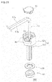
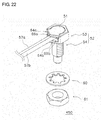
- Fig. 22 is a perspective view showing the appearance of the diffusive-reflective optical fiber unit 450.
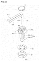
- Fig. 23 is an exploded perspective view of the optical fiber unit 450.
- each of the optical fiber cables 57a and 57b in the diffusive-reflective optical fiber unit 450 is uncovered by removing the coating material, and thus optical fibers 73a and 73b are exposed.
- the optical fiber 73a extends from the optical fiber cable 57a.
- the optical fiber73b extends from the optical fiber cable 57b.
- the optical fibers 73a and 73b uncovered by removing the coating material are inserted in the through-hole 65 of the shaft 54.
- the shaft 54 includes a first shaft 54-1 having a larger diameter and a second shaft 54-2 having a smaller diameter.
- the optical fiber unit 450 accommodates the optical fibers 73a and 73b of the optical fiber unit 450 inserted through the through-hole 65.
- the reflective optical fiber unit 250 eliminates the lens member 55, which is included in the reflective optical fiber unit 250 according to the second embodiment.
- the optical fiber unit 450 with the above structure includes a first opening 69a formed in a first side 64a, and a second opening 69b formed in a second side 64b in the same manner as the optical fiber unit 250 in the second embodiment.
- the optical fiber cables 57a and 57b extend through the corner between the first opening 69a and the second opening 69b in a direction parallel to the third side 64d and the fourth side 64c.
- the opening 69 includes two openings, or specifically the first opening 69a and the second opening 69b as shown in Fig. 1 and similar figures.
- the opening 69 may include a single opening, or specifically either the first opening 69a or the second opening 69b.
- the opening 69 may be formed in a single side.
- the optical fiber cable 57 extends from either the first opening 69a or the second opening 69b in a direction parallel to the third side 64d and the fourth side 64c.
- Fig. 24 is a perspective view of a modification in which the opening 69 is at a different position. As shown in Fig. 24 , the opening 69 is formed in only the second side 64b.
- the optical fiber cable 57 extends from the opening 69 in a direction parallel to the third side 64d and the fourth side 64c.
- the opening 69 may be formed in any number of sides other than a single side, although the opening 69 may be formed in a single side. Alternatively, the opening 69 may be formed across three or more sides.
- the optical fiber unit includes the cover 51.
- the optical fiber unit may eliminate the cover 51.
- the use of the cover 51 is preferable when the bent optical fiber cable 57 is to be accommodated in the space 68 of the head 53.
- the optical fiber unit of the present invention for an optical fiber sensor enables secure grasping of the optical fiber unit with the jig while avoiding damage to the optical fiber cable.
Landscapes
- Physics & Mathematics (AREA)
- General Physics & Mathematics (AREA)
- Optics & Photonics (AREA)
- Investigating Or Analysing Materials By Optical Means (AREA)
- Light Guides In General And Applications Therefor (AREA)
- Optical Transform (AREA)
- Geophysics And Detection Of Objects (AREA)
- Engineering & Computer Science (AREA)
- General Engineering & Computer Science (AREA)
- Optical Couplings Of Light Guides (AREA)
- Mechanical Engineering (AREA)
Abstract
Description
- The present invention relates to an optical fiber unit for an optical fiber sensor.
-
Patent Literature 1 describes anoptical fiber unit 10.Fig. 25 is a perspective view of theoptical fiber unit 10 described inPatent Literature 1.Fig. 26 is a perspective exploded view of theoptical fiber unit 10. - As shown in
Fig. 26 , theoptical fiber unit 10 described inPatent Literature 1 includes ahead 11, acover 12, and anut 13. Thehead 11 includes acylindrical portion 14 and anoptical fiber holder 17. Thecylindrical portion 14 includes a through-hole 18, in which anoptical fiber cable 15 is inserted. Theoptical fiber holder 17 includes agroove 22, which communicates with the through-hole 18. Theoptical fiber holder 17 is shaped in a hexagonal prism defining thegroove 22. Theoptical fiber holder 17 has an opening 23 in one side of its periphery. Theoptical fiber cable 15 is inserted in the through-hole 18 of thecylindrical portion 14 and in thegroove 22 of theoptical fiber holder 17, bent at a predetermined curvature and then extends from theopening 23. - Patent Literature 1: Japanese Unexamined Patent Application Publication No.
2005-156455 - In the
optical fiber unit 10 described inPatent Literature 1, theoptical fiber cable 15 extends from the opening 23 formed in one side of the hexagonal prism. Theoptical fiber cable 15 extends in a direction that is not parallel to the sides on which ajig 30, such as a spanner, is set. In this case, thejig 30, such as a spanner, set on theoptical fiber holder 17 can come in contact with theoptical fiber cable 15 and damage theoptical fiber cable 15. If such contact with theoptical fiber cable 15 is to be avoided, thejig 30 cannot be completely engaged with theoptical fiber holder 17.Fig. 27 is a schematic view showing thejig 30 set on theoptical fiber holder 17. If thejig 30 set in the state shown inFig. 27 is further pushed in to engage with theoptical fiber holder 17 at its deeper position, thejig 30 can come in contact with theoptical fiber cable 15 and damage theoptical fiber cable 15. If such contact with theoptical fiber cable 15 is avoided in the manner shown inFig. 27 , thejig 30 would be set incompletely on theoptical fiber holder 17, disabling secure grasping of theoptical fiber holder 17 with the jig. - It is an object of the present invention to provide an optical fiber unit for an optical fiber sensor that enables secure grasping of the optical fiber unit with a jig while avoiding damage to an optical fiber cable.
- An optical fiber unit for an optical fiber sensor according to one aspect of the invention includes an optical fiber cable, a shaft, and a head. The shaft includes a peripheral surface having a male thread, and a through-hole in which the optical fiber cable is inserted. The head is shaped in a hexagonal prism and including six sides and a bottom. The shaft is connected to the bottom of the head. The optical fiber cable extends inside the head, and extends out of the head in a direction substantially parallel to two parallel sides of the six sides from at least one of the six sides other than the two parallel sides.
- The above structure allows the optical fiber cable to extend substantially parallel to two parallel sides of the six sides of the head. Even when a jig, such as a spanner, is pushed in deeply along the two parallel sides, the tip of the jig is less likely to come in contact with the optical fiber cable. This structure thus prevents damage to the optical fiber cable, which can occur when the jig is set. As a result, the jig can be pushed in to engage with the head at its deep position, enabling secure grasping of the optical fiber unit for an optical fiber sensor with the jig.
- It is preferable that the optical fiber cable extends from a first side that is one of the six sides other than the two parallel sides and a second side that is adjacent to the first side and is another one of the six sides other than the two parallel sidesby extending through a corner formed between the first side and the second side. This structure allows the optical fiber cable to extend through the through-hole of the shaft, and extends from the corner between the first side and the second side of the head. The direction from the through-hole of the shaft to the corner between the first side and the second side is substantially parallel to the two parallel sides. In this case, the optical fiber cable, which extends through the corner between the first side and the second side of the head, extends in the direction substantially parallel to the two parallel sides. When the jig is pushed in deeply along the two parallel sides, the tip of the jig is prevented from coming in contact with the optical fiber cable and thus from damaging the optical fiber cable. As a result, the jig can be pushed in to engage with the head at its deep position, enabling secure grasping of the optical fiber unit for an optical fiber sensor with the jig.
- It is preferable that the head includes a space through which the optical fiber cable is inserted, and the space communicates with the through-hole. The space is exposed at an opening formed across the corner. The opening may be defined by the remaining edges of the sides of the head. This structure allows the optical fiber cable to extend through the through-hole of the shaft, be bent and extend in the space, and extend from the opening. The opening is formed across the corner between the first side and the second side of the head. The space is exposed at this opening. As a result, the optical fiber cable extends through or around the corner between the first side and the second side and extends from the opening. Thus, the optical fiber cable extends in the direction substantially parallel to the two parallel sides. As described above, this structure enables secure grasping of the head with the jig while avoiding damage to the optical fiber cable.
- It is preferable that the optical fiber cable includes a single cable. This structure enables secure grasping of the head with the jig in a transmissive optical fiber sensor, while avoiding damage to the optical fiber cable in the same manner as described above.
- It is preferable that the optical fiber cable includes a first cable and a second cable. This structure enables secure grasping of the head with the jig in a reflective optical fiber sensor, while avoiding damage to the optical fiber cable in the same manner as described above.
- The present invention provides an optical fiber unit for an optical fiber sensor that enables secure grasping of the optical fiber unit with a jig while avoiding damage to an optical fiber cable.
-
-
Fig. 1 is a perspective view showing the appearance of an optical fiber unit according to a first embodiment. -
Fig. 2 is an exploded perspective view of the optical fiber unit according to the first embodiment. -
Fig. 3 is an enlarged bottom view of the optical fiber unit according to the first embodiment. -
Fig. 4 is a cross-sectional view taken on line A-A inFig. 3 . -
Fig. 5 is a plan view of a holder according to the first embodiment. -
Fig. 6 is a schematic view showing the positional relationship between the optical fiber cable and the jig. -
Fig. 7 is a schematic view of another example in which the optical fiber cable extends in a different manner. -
Fig. 8 is a diagram describing a procedure for installing the optical fiber unit according to the first embodiment. -
Fig. 9 is a schematic view of a modification in which the optical fiber cable extends in a different manner. -
Fig. 10 is a perspective view showing the appearance of the optical fiber unit according to the first embodiment. -
Fig. 11 is a perspective view showing the appearance of an optical fiber unit according to a second embodiment. -
Fig. 12 is an exploded perspective view of the optical fiber unit according to the second embodiment. -
Fig. 13 is an enlarged bottom view of the optical fiber unit according to the second embodiment. -
Fig. 14 is a cross-sectional view taken on line B-B inFig. 13 . -
Fig. 15 is a plan view of the optical fiber unit according to the second embodiment from which the cover has been removed. -
Fig. 16 is a schematic view showing the positional relationship between the optical fiber cable and the jig. -
Fig. 17 is a diagram describing a procedure for installing the optical fiber unit according to the second embodiment. -
Fig. 18 is a schematic view of a first modification in which the optical fiber cable extends in a different manner. -
Fig. 19 is a schematic view of a second modification in which the optical fiber cable extends in a different manner. -
Fig. 20 is a perspective view showing the appearance of a coaxial reflective optical fiber unit according to a first modification of the second embodiment. -
Fig. 21 is an exploded perspective view of a coaxial reflective optical fiber unit according to a first modification of the second embodiment. -
Fig. 22 is a perspective view showing the appearance of a diffusion reflective optical fiber unit according to a second modification of the second embodiment. -
Fig. 23 is an exploded perspective view of the diffusion reflective optical fiber unit according to the second modification of the second embodiment. -
Fig. 24 is a perspective view of a modification in which the opening is at a different position. -
Fig. 25 is a perspective view of an optical fiber unit according to a technique known in the art. -
Fig. 26 is an exploded perspective view of the optical fiber unit according to the technique known in the art. -
Fig. 27 is a diagram describing a method for using a jig on the optical fiber unit according to the technique known in the art. - Embodiments of the present invention will now be described with reference to the drawings. The embodiments described below are mere examples of the present invention, and should not limit the technical scope of the invention.
- Although the invention is applicable to various optical fiber sensors, an
optical fiber unit 50 for a transmissive optical fiber sensor will be described first. -
Fig. 1 is a perspective view showing the appearance of anoptical fiber unit 50 according to a first embodiment used for a transmissive optical fiber sensor.Fig. 2 is an exploded perspective view of theoptical fiber unit 50.Fig. 3 is an enlarged bottom view of theoptical fiber unit 50.Fig. 4 is a cross-sectional view taken on line A-A inFig. 3 . - The
optical fiber unit 50 includes acover 51, aninstallation member 52, alens member 55, awasher 60, anut 61, and anoptical fiber cable 57. In the example described below, thecover 51 is on the upper side of theoptical fiber unit 50, and thenut 61 is on the lower side of theoptical fiber unit 50 as shown inFigs. 1 to 2 and similar figures. The direction orthogonal to the longitudinal direction of theoptical fiber unit 50 is referred to as a planar direction. - The
installation member 52 and thenut 61 are made of metal. To maintain a predetermined strength, theinstallation member 52 and thenut 61 in one example are formed by zinc die casting and are plated with chromium. Theinstallation member 52 is used to install theoptical fiber cable 57 onto, for example, a manufacturing line (described later). Theinstallation member 52 includes ashaft 54 and ahead 53. - The
shaft 54 has an internal through-hole 65, which is formed through theshaft 54 in its longitudinal direction. As described below, theoptical fiber cable 57 and thelens member 55 are inserted in the through-hole 65. Theoptical fiber cable 57 is bent at a predetermined curvature as shown inFig. 2 and is inserted in the through-hole 65. - The
shaft 54 has amale thread 54a formed on a portion of its peripheral surface. As shown inFig. 2 , the peripheral surface of theshaft 54 includes a flat portion without themale thread 54a. However, the outer shape of theshaft 54 is not limited to this shape. Theshaft 54 may be entirely cylindrical and may include themale thread 54a across its entire circumference. - The
head 53 is arranged on top of theshaft 54. Thehead 53 is integral with theshaft 54. Alternatively, thehead 53 may be separate from theshaft 54. Thehead 53 has a greater outer diameter than theshaft 54, and is shaped in a substantially hexagonal prism. In the present embodiment, thehead 53 is shaped in a regular hexagonal prism. Thehead 53 includes a bottom 62 and anouter wall 64. The bottom 62 comes in contact with theshaft 54. The bottom 62 is shaped in a substantially hexagonal plate. Theouter wall 64 protrudes upward from the bottom 62. The bottom 62 and theouter wall 64 define aspace 68. Thespace 68 extends radially outwardly from the through-hole 65 of theshaft 54. - The
space 68 communicates with the through-hole 65 of theshaft 54. A communicating portion between the through-hole 65 of theshaft 54 and thespace 68 includes a taperedportion 62a, which results from forming a tapered end of the through-hole 65. More specifically, the bottom 62 includes the taperedportion 62a, which communicates with the through-hole 65 of theshaft 54. The taperedportion 62a provides communication between thespace 68 and the through-hole 65, and allows theoptical fiber cable 57 to be inserted in the through-hole 65 from above theshaft 54. This structure further allows theoptical fiber cable 57 to fix at the through-hole 65 along the curvature of theoptical fiber cable 57, allowing more flexibility of theoptical fiber cable 57 in the planar direction than the structure without the taperedportion 62a. Further, thespace 68 is larger, or specifically wider than the through-hole 65 at positions more away from the through-hole 65, allowing theoptical fiber cable 57 extending from thespace 68 though an opening 69 (not shown) to move within a wider area. - The
head 53 includes a plurality of sides. In the present embodiment, thehead 53 is shaped in a hexagonal prism. Thus, thehead 53 has six sides.Fig. 5 is a plan view of theinstallation member 52. More specifically, as shown inFig. 5 , thehead 53 includes afirst side 64a, asecond side 64b, athird side 64d, afourth side 64c, afifth side 64e, and asixth side 64f. Thesecond side 64b is adjacent to thefirst side 64a on one end of thefirst side 64a. Thethird side 64d is adjacent to thefirst side 64a on the other end of thefirst side 64a. Thefourth side 64c is adjacent to thesecond side 64b. More specifically, thefirst side 64a is between and is adjacent to thesecond side 64b and thethird side 64d. Thesecond side 64b is between and is adjacent to thefirst side 64a and thefourth side 64c. Thefourth side 64c is parallel to thethird side 64d. Thefifth side 64e is parallel to thefourth side 64c. Thefifth side 64e is parallel to thefirst side 64a. Thesixth side 64f is adjacent to thefifth side 64e. Thesixth side 64f is parallel to thesecond side 64b. - The
outer wall 64 has anopening 69. Theopening 69 includes afirst opening 69a formed in thefirst side 64a, and asecond opening 69b formed in thesecond side 64b. Thefirst opening 69a and thesecond opening 69b communicate with each other. - As shown in
Fig. 5 , theopening 69 has a width D3 greater than a width Da of thefirst side 64a. The width D3 of theopening 69 is greater than a width Db of thesecond side 64b. Thefirst opening 69a has a width D1 greater than or equal to the diameter of theoptical fiber cable 57. Thesecond opening 69a has a width D2 greater than or equal to the diameter of theoptical fiber cable 57. The width D1 of thefirst opening 69a is equal to the width D2 of thesecond opening 69a. Alternatively, the width D1 of thefirst opening 69a may differ from the width D2 of thesecond opening 69a. - The
space 68 defined by theouter wall 64 communicates with the through-hole 65 of theshaft 54, with the taperedportion 62a between thespace 68 and the through-hole 65. Anattachment wall 67, which protrudes radially inward, is arranged on the inner surface of theouter wall 64. The upper surface of theattachment wall 67 is located lower than the upper surface of theouter wall 64 by the distance corresponding to the thickness of thecover 51. Thecover 51 is placed on theattachment wall 67. - As shown in
Fig. 1 , thecover 51 is attached to the top of thehead 53. Thecover 51 is a lid for closing thespace 68 of thehead 53 in the axial direction of the through-hole 65 of theshaft 54. In detail, thecover 51 is set to close thespace 68 from above. Theoptical fiber cable 57 is bent in a direction from the through-hole 65 of theshaft 54 toward theopening 69 of thespace 68. Thecover 51 allows this bentoptical fiber cable 57 to be accommodated in thespace 68 in an appropriate manner. - As shown in
Fig. 2 , thecover 51 includes aflat plate 51a and aguide 51b. Theflat plate 51a is a plate member. The outer shape of theflat plate 51a includes anarc portion 51a-11, joiningportions 51a-2, afirst side 51c, and asecond side 51d. Thefirst side 51c and thesecond side 51d correspond to theopening 69 of thehead 53, and are two straight sides adjacent to each other. Thefirst side 51c and thesecond side 51 d are in conformance with the hexagonal sides of the bottom 62 of thehead 53. More specifically, when thecover 51 is placed on theattachment wall 67, thefirst side 51c and thesecond side 51d correspond to the sides of thehexagonal bottom 62. In more detail, thefirst side 51c is flush with thefirst side 64a, and thesecond side 51 d is flush with thesecond side 64b as viewed from above. As viewed from above, thefirst side 51c and thesecond side 51d are substantially parallel to two of the sides of the hexagonal bottom 62 corresponding to theopening 69. - The
arc portion 51a-1 is sized in conformance with the opening formed in the upper surface of theouter wall 64. The joiningportions 51a-2 join thearc portion 51a-1 with thefirst side 51c and with thesecond side 51d. - The
guide 51b protrudes downward in a direction orthogonal to theflat plate 51a, and is shaped to engage with theattachment wall 67 of thehead 53. Theattachment wall 67 includes aguide groove 67a. When thecover 51 is attached to thehead 53, a protrusion (not shown) on theguide 51b is guided along theguide groove 67a. In thecover 51 attached to thehead 53, thefirst side 51c is flush with thefirst side 64a, and thesecond side 51d is flush with thesecond side 64b. - The
lens member 55 is a cylindrical lens. Thelens member 55 is inserted in the through-hole 65 of theshaft 54, and is fixed to the tip of theoptical fiber cable 57. Thelens member 55 can focus light from theoptical fiber cable 57. Thelens member 55 is not an essential component, and can be replaced by an elongated portion of an optical fiber of theoptical fiber cable 57. - The
nut 61 has a female thread, which is screwed with the male thread of theshaft 54. The male thread of theshaft 54 and the female thread of thenut 61 are screwed together to fix theoptical fiber unit 50. Thewasher 60 is arranged between thenut 61 and thehead 53. Thewasher 60 may be eliminated. - The manner in which the
optical fiber cable 57 extends will now be described with reference toFig. 6 . Theoptical fiber cable 57 extends through the corner between thefirst side 64a and thesecond side 64b. Theoptical fiber cable 57 extending from the corner extends parallel to thethird side 64d and thefourth side 64c. - As shown in
Fig. 6 , even when thehead 53 is pushed in deeply against thejig 80,tips jig 80 do not come in contact with theoptical fiber cable 57. This structure prevents damage to theoptical fiber cable 57, which can occur when thejig 80 is set. This structure further allows thehead 53 to be pushed in deeply against thejig 80 without bending theoptical fiber cable 57, and thus enables secure grasping of theoptical fiber unit 50 with thejig 80. - The
opening 69 of thehead 53 includes thefirst opening 69a in thefirst side 64a, and thesecond opening 69b in thesecond side 64b. Theopening 69 is formed across the corner between thefirst side 64a and thesecond side 64b. Thespace 68 is exposed at theopening 69. More specifically, thespace 68 is exposed across the corner between thefirst side 64a and thesecond side 64b. In this manner, thespace 68 exposed at theopening 69 allows theoptical fiber cable 57 to extend parallel to thethird side 64d and thefourth side 64c. - The
optical fiber cable 57 may not extend completely parallel to thethird side 64d and thefourth side 64c but may extend in a slightly deviating direction. For example, theoptical fiber cable 57 may extend in the manner shown inFig. 7 . In the example ofFig. 7 , theoptical fiber cable 57 has acentral axis 58 within the range of about ± 10° relative to acentral axis 59 that is aligned with the center of thehead 53 and is parallel to thethird side 64d and thefourth side 64c. - A method for assembling the
optical fiber cable 57 will now be described with reference toFig. 2 . - The
optical fiber cable 57 is coated with a coating material, such as polyester. Of the two distal ends of theoptical fiber cable 57, one distal end to be placed into theoptical fiber unit 50 is uncovered by removing the coating material. - The
optical fiber cable 57 is bent at a predetermined curvature. Adhesive is then applied to or filled in theoptical fiber cable 57 and/or the through-hole 65 to fix theoptical fiber cable 57 at the through-hole 65 of theshaft 54. As a result, theoptical fiber cable 57 extends parallel to thethird side 64d and thefourth side 64c as described above. - The
cover 51 is attached to thehead 53 to cover the upper portion of thehead 53. Thefirst side 51c and thesecond side 51d of thecover 51 are located to correspond to the sides of thehexagonal bottom 62. More specifically, thefirst side 51c is flush with thefirst side 64a. Thesecond side 51d is flush with thesecond side 64b. This structure enables easy and secure grasping of thefirst side 51c and thefifth side 64e of thehead 53 with thejig 80, such as a spanner, when theoptical fiber unit 50 is installed. Likewise, this structure also enables easy and secure grasping of thesecond side 51 d and thesixth side 64f of thehead 53. As a result, thefirst side 64a having thefirst opening 69a or thesecond side 64b having thesecond opening 69b can be grasped with thejig 80. - In an area α indicated by a broken line in
Fig. 1 , the L-shape joining portion 51a-2 of thecover 51 is engaged with theouter wall 64 to increase the strength of the structure when thejig 80 is set on thefirst side 51c or thesecond side 51 d of thecover 51. - The
lens member 55 is placed in the through-hole 65 of theshaft 54 from below, and is fixed in contact with the tip of theoptical fiber cable 57. This completes the assembling processes of theoptical fiber unit 50. - The assembling procedure described above is a mere example. The assembling procedure should not be limited to the procedure described above. For example, the
lens member 55 may be inserted in the through-hole 65 before theoptical fiber cable 57 is fixed at the through-hole 65. Theoptical fiber cable 57 may be bent after fixed at the through-hole 65. - The
head 53 without thelens member 55 eliminates the need for the process of inserting thelens member 55 in the through-hole 65. In thehead 53 without thelens member 55, the optical fiber included in theoptical fiber cable 57 is uncovered at positions lower than where the coating material has been removed. The uncovered portion of the optical fiber extends in the through-hole 63. - The installation of the
optical fiber unit 50 assembled as described above will now be described.Fig. 8 is a diagram describing the procedure for installing theoptical fiber unit 50. - As shown in
Fig. 8 , theoptical fiber unit 50 is installed on, for example, a manufacturing line L, on which a workpiece W is transported on a conveyer V The manufacturing line L includes a side wall H1 and a side wall H2. - A pair of
optical fiber units 50 for projecting light and for receiving light is installed. Openings are formed in the side walls H1 and H2 at positions where theoptical fiber units 50 for projecting light and receiving light are to be installed. Theshaft 54 of each of theoptical fiber units 50 for projecting light and receiving light is inserted in the corresponding opening. Thenut 61 is then screwed with themale thread 54a of theshaft 54. Theoptical fiber cable 57 extends through the corner between thefirst opening 69a and thesecond opening 69b and extends parallel to thethird side 64d and thefourth side 64c. When thehead 53 is pushed in deeply against thejig 80 in the screwing process and thethird side 64d and thefourth side 64c are grasped with thejig 80, thejig 80 does not come in contact with theoptical fiber cable 57. As described above, this structure thus enables secure grasping of theoptical fiber unit 50 with thejig 80 while avoiding damage to theoptical fiber cable 57. - As described above, the
optical fiber units 50 for projecting light and for receiving light are fixed to the corresponding side walls H1 and H2 as shown inFig. 8 . Theoptical fiber cable 57 is set along the side wall H1 and the side wall H2. - The
optical fiber cable 57 extending from theoptical fiber unit 50 is connected to theoptical sensor unit 90. Theoptical sensor unit 90 includes alight projector 92 incorporating a light emitting element, alight receiver 93 incorporating a light receiving element, acontroller 91, and adisplay 94. Thecontroller 91 includes various circuits for centrally controlling theoptical sensor unit 90. Thedisplay 94 displays the detected status of the workpiece W and also displays the settings. - The light projecting
optical fiber unit 50, which is fixed to the side wall H1, is connected to thelight projector 92. The light receivingoptical fiber unit 50, which is fixed to the side wall H2, is connected to thelight receiver 93. - As described above, the
optical fiber unit 50 is installed to complete the optical fiber sensor S1 including theoptical fiber unit 50 and theoptical sensor unit 90. The optical fiber sensor S1 detects the status of the workpiece W being transported in accordance with the movement of the conveyer V -
Fig. 9 is a schematic view of theoptical fiber cable 57 that extends in a modified manner. As shown inFig. 9 , theoptical fiber cable 57 extends from thefirst side 64a in a direction parallel to thethird side 64d and thefourth side 64c. InFig. 9 , theoptical fiber cable 57 extends from thefirst side 64a. Alternatively, theoptical fiber cable 57 may extend from thesecond side 64b in the direction parallel to thethird side 64d and thefourth side 64c. - The
opening 69 may have a shape different from the shape described in the first embodiment. For example,Fig. 10 is a perspective view showing the appearance of anoptical fiber unit 150 according to a modification. Theopening 69 of theoptical fiber unit 150 has a width smaller than the width of thefirst side 64a or the width of thesecond side 64b. For example, theopening 69 of theoptical fiber unit 150 has a width substantially equal to the diameter of theoptical fiber cable 57. The other components of theoptical fiber unit 150 are the same as the corresponding components of theoptical fiber unit 50 in the first embodiment described above, and will not be described. - An
optical fiber unit 250 for a reflective optical fiber sensor will now be described. -
Fig. 11 is a perspective view showing the appearance of theoptical fiber unit 250 for a reflective optical fiber sensor according to a second embodiment.Fig. 12 is an exploded perspective view of theoptical fiber unit 250.Fig. 13 is an enlarged bottom view of theoptical fiber unit 250.Fig. 14 is a cross-sectional view taken on line B-B inFig. 13 .Fig. 15 is a plan view of theoptical fiber unit 250 from which thecover 51 has been removed. - The reflective
optical fiber unit 250 according to the second embodiment will now be described. The reflectiveoptical fiber unit 250 according to the second embodiment differs from the transmissiveoptical fiber unit 50 according to the first embodiment in that it includes twooptical fiber cables lens members optical fiber cables lens members optical fiber unit 250 includes acover 51, ahead 53, ashaft 54, awasher 60, and anut 61 that are all larger than the corresponding components of theoptical fiber unit 50 of the first embodiment. The other components are substantially the same as described in the first embodiment, and the components that are the same as the components of the transmissiveoptical fiber unit 50 in the first embodiment will be described briefly or will not be described. - The reflective
optical fiber unit 250 according to the second embodiment includes the twooptical fiber cables optical fiber cables optical fiber cable 57 described in the first embodiment. - The
optical fiber unit 250 includes thecover 51, thehead 53, theshaft 54, thelens members 55, and thenut 61. The twolens members optical fiber cables lens members optical fiber cables - The
shaft 54 has a through-hole 65, which extends through theshaft 54 in its longitudinal direction. The through-hole 65 is sized to accommodate the twooptical fiber cables Figs. 13 and15 , the through-hole 65 includes a first through-hole 65a and a second through-hole 65b. The first through-hole 65a receives theoptical fiber cable 57a. The second through-hole 65b receives theoptical fiber cable 57b. In the second embodiment, the twooptical fiber cables optical fiber cable 57a and theoptical fiber cable 57b separate in the vicinity of the through-hole 65. The first through-hole 65a and the second through-hole 65b may be separate from each other or may communicate with each other. - The
head 53, which is arranged on top of theshaft 54, includes a bottom 62 and anouter wall 64. The bottom 62 and theouter wall 64 define aspace 68. In the second embodiment, thespace 68 has a circular portion having a diameter large enough to allow the twooptical fiber cables space 68 communicates with the through-hole 65 of theshaft 54. The through-hole 65 may include a taperedportion 62a, which results from forming a tapered end of the through-hole 65 in the communicating portion between the through-hole 65 of theshaft 54 and thespace 68. - As shown in
Figs. 11 and12 , theouter wall 64 may be eliminated from two adjacent sides of the hexagonal bottom 62, and instead an opening 69 may be formed in the adjacent sides. More specifically, theopening 69 includes afirst opening 69a and asecond opening 69b, which are adjacent to each other. Thefirst opening 69a is formed in thefirst side 64a. Thesecond opening 69b is formed in thesecond side 64b. - An
attachment wall 67, which protrudes radially inward, is arranged on the inner surface of theouter wall 64. The upper surface of theattachment wall 67 is located lower than the upper surface of theouter wall 64 by the distance corresponding to the thickness of thecover 51. Theattachment wall 67 shown inFig. 12 is arranged across the entire circumference of theouter wall 64. - The
cover 51 is attached to the top of thehead 53. Thecover 51 includes aflat plate 51a and aguide 51b. The outer shape of theflat plate 51a includes anarc portion 51a-1, joiningportions 51a-2, afirst side 51c, and asecond side 51 d. Thefirst side 51c and thesecond side 51 d correspond to theopening 69 of thehead 53, and are two straight sides adjacent to each other. When thecover 51 is placed on theattachment wall 67, thefirst side 51c is flush with thefirst side 64a, and thesecond side 51 d is flush with thesecond side 64b as viewed from above. Theguide 51b is engaged along theattachment wall 67 of thehead 53. - The two
optical fiber cables corresponding lens members lens member 55a is fixed to the tip of theoptical fiber cable 57a. Thelens member 55b is fixed to the tip of theoptical fiber cable 57b. - The
nut 61 is screwed with the male thread of theshaft 54 to fix theoptical fiber unit 250. Thewasher 60 is arranged between thenut 61 and thehead 53. Thewasher 60 may be eliminated. - The manner in which the
optical fiber cables Fig. 16. Fig. 16 is a schematic view showing the relationship between the optical fiber cables and the jig. - As shown in
Fig. 16 , theoptical fiber cables first side 64a and thesecond side 64b. Theoptical fiber cables third side 64d and thefourth side 64c. - The
optical fiber cables third side 64d and thefourth side 64c, and thus are prevented from coming in contact with thejig 80, such as a spanner, in the same manner as described in the first embodiment. As in the first embodiment, this structure enables secure grasping of theoptical fiber unit 50 with thejig 80 while avoiding damage to theoptical fiber cables - As in the first embodiment, the
optical fiber cables third side 64d and thefourth side 64c but may extend in a slightly deviating direction. For example, theoptical fiber cables 57 have acentral axis 58 within the range of about ±10° relative to acentral axis 59 aligned with the center of thehead 53 and parallel to thethird side 64d and thefourth side 64c. - A method for assembling the
optical fiber cable Fig. 12 . The method is substantially the same as the assembling method of the first embodiment described with reference toFig. 2 , and will be described briefly. - Of the two distal ends of each of the
optical fiber cables optical fiber unit 250 is uncovered by removing the coating material. - The
optical fiber cables optical fiber cables hole 65 to fix theoptical fiber cables hole 65 of theshaft 54. As a result, theoptical fiber cables third side 64d and thefourth side 64c as described above. Theguide 51b of thecover 51 is placed along theattachment wall 67 of thehead 53. As a result, thecover 51 is attached to thehead 53. - Subsequently, the
lens members hole 65 of theshaft 54, and are fixed in contact with the tips of the correspondingoptical fiber cable optical fiber unit 250. - The installation of the
optical fiber unit 250 assembled as described above will now be described.Fig. 17 is a diagram describing the procedure for installing theoptical fiber unit 250. - As shown in
Fig. 17 , theoptical fiber unit 250 is installed on, for example, a manufacturing line L on which a workpiece W is transported on a conveyer V The manufacturing line L includes a side wall H1 and a side wall H2. - An opening is formed at a predetermined position where the
optical fiber unit 250 is to be installed. Theshaft 54 of theoptical fiber unit 250 is inserted in the opening. Thenut 61 is then screwed with themale thread 54a of theshaft 54. Theoptical fiber cables first opening 69a and thesecond opening 69b and extend parallel to thethird side 64d and thefourth side 64c. When thehead 53 is pushed in deeply against thejig 80 in the screwing process and thethird side 64d and thefourth side 64c are grasped with thejig 80, thejig 80 does not come in contact with theoptical fiber cable optical fiber unit 50 with thejig 80 while avoiding damage to theoptical fiber cables - As described above, the reflective
optical fiber unit 250 is fixed to the side wall H1 as shown inFig. 17 . Theoptical fiber cables optical fiber unit 250 are fixed to theoptical sensor unit 90. For example, theoptical fiber cable 57a for projecting light is connected to thelight projector 92. Theoptical fiber cable 57b for receiving light is connected to thelight receiver 93. - As described above, the
optical fiber unit 250 is installed to complete the optical fiber sensor S2 including theoptical fiber unit 250 and theoptical sensor unit 90. The optical fiber sensor S2 detects the status of the workpiece W being transported in accordance with the movement of the conveyer V - The
optical fiber cable 57 may extend in a manner different from the above-described manner. For example,Fig. 18 is a schematic view of theoptical fiber cables Fig. 18 , theoptical fiber cables first side 64a in a direction parallel to thethird side 64d and thefourth side 64c. Although theoptical fiber cables first side 64a inFig. 18 , theoptical fiber cables second side 64b in a direction parallel to thethird side 64d and thefourth side 64c. - As shown in
Fig. 19 , theoptical fiber cable 57a extends from thefirst side 64a in a direction parallel to thethird side 64d and thefourth side 64c. Theoptical fiber cable 57b extends from thesecond side 64b in a direction parallel to thethird side 64d and thefourth side 64c. Theoptical fiber cable 57a and theoptical fiber cable 57b are separate from each other. None of theoptical fiber cable 57a or theoptical fiber cable 57b passes through the corner between thefirst side 64a and thesecond side 64b. - As described in the first modification or the second modification, the
optical fiber cables third side 64d and thefourth side 64c. In the same manner as described in the second embodiment, this structure prevents theoptical fiber cables jig 80, such as a spanner. In the same manner as in the second embodiment, this structure enables secure grasping of theoptical fiber unit 50 with thejig 80 while avoiding damage to theoptical fiber cables - The invention is applicable to other optical fiber sensors including a coaxial reflective optical fiber sensor and a diffusive-reflective optical fiber sensor. The
optical fiber units - 5-1. Coaxial Reflective
Optical Fiber Unit 350 - A coaxial reflective
optical fiber unit 350 according to a first modification will now be described. - The coaxial reflective
optical fiber unit 350 according to a first modification of the second embodiment differs from the reflectiveoptical fiber unit 250 according to the second embodiment in the components described below. The other components that are the same as in the second embodiment will not be described. -
Fig. 20 is a perspective view showing the appearance of the coaxial reflectiveoptical fiber unit 350.Fig. 21 is an exploded perspective view of theoptical fiber unit 350. - The distal end of each of the
optical fiber cables optical fiber 70 is exposed. Theoptical fiber 70 includes an optical fiber for projecting light and an optical fiber for receiving light that are integrated together. In one example, theoptical fiber 70 may include the optical fiber for projecting light arranged at the center, which is surrounded by the optical fiber for receiving light. - The
optical fiber 70 uncovered by removing the coating material is inserted in the through-hole 65 of theshaft 54. Theshaft 54 has a smaller diameter than theshaft 54 of theoptical fiber unit 250 described in the second embodiment. The portion of the through-hole 65 for receiving the distal ends of theoptical fiber cables optical fiber cables optical fiber 70 of theoptical fiber unit 350 is inserted through the through-hole 65. Thus, theoptical fiber unit 350 eliminates thelens member 55, which is included in the reflectiveoptical fiber unit 250 of the second embodiment. - The
optical fiber unit 350 with the above structure includes afirst opening 69a formed in afirst side 64a, and asecond opening 69b formed in asecond side 64b in the same manner as theoptical fiber unit 250 according to the second embodiment. Theoptical fiber cables first opening 69a and thesecond opening 69b in a direction parallel to thethird side 64d and thefourth side 64c. Even when thehead 53 is pushed in deeply against thejig 80 in the screwing process and thethird side 64d and thefourth side 64c are grasped with thejig 80, thejig 80 does not come in contact with theoptical fiber cables optical fiber unit 350 with thejig 80 while avoiding damage to theoptical fiber cables - A diffusive-reflective
optical fiber unit 450 according to a second modification will now be described. - The diffusive-reflective
optical fiber unit 450 according to a second modification of the second embodiment differs from the reflectiveoptical fiber unit 250 according to the second embodiment in the components described below. The other components that are the same as in the first modification will not be described. -
Fig. 22 is a perspective view showing the appearance of the diffusive-reflectiveoptical fiber unit 450.Fig. 23 is an exploded perspective view of theoptical fiber unit 450. - The distal end of each of the
optical fiber cables optical fiber unit 450 is uncovered by removing the coating material, and thusoptical fibers optical fiber 73a extends from theoptical fiber cable 57a. The optical fiber73b extends from theoptical fiber cable 57b. - The
optical fibers hole 65 of theshaft 54. Theshaft 54 includes a first shaft 54-1 having a larger diameter and a second shaft 54-2 having a smaller diameter. Theoptical fiber unit 450 accommodates theoptical fibers optical fiber unit 450 inserted through the through-hole 65. Thus, the reflectiveoptical fiber unit 250 eliminates thelens member 55, which is included in the reflectiveoptical fiber unit 250 according to the second embodiment. - The
optical fiber unit 450 with the above structure includes afirst opening 69a formed in afirst side 64a, and asecond opening 69b formed in asecond side 64b in the same manner as theoptical fiber unit 250 in the second embodiment. Theoptical fiber cables first opening 69a and thesecond opening 69b in a direction parallel to thethird side 64d and thefourth side 64c. When thehead 53 is pushed in deeply against thejig 80 in the screwing process and thethird side 64d and thefourth side 64c are grasped with thejig 80, thejig 80 does not come in contact with theoptical fiber cables optical fiber unit 50 with thejig 80 while avoiding damage to theoptical fiber cables - The above embodiments may be modified in the following forms.
- (a) In the above embodiments, the
opening 69 includes two openings, or specifically thefirst opening 69a and thesecond opening 69b as shown inFig. 1 and similar figures. Alternatively, theopening 69 may include a single opening, or specifically either thefirst opening 69a or thesecond opening 69b. In other words, theopening 69 may be formed in a single side. Theoptical fiber cable 57 extends from either thefirst opening 69a or thesecond opening 69b in a direction parallel to thethird side 64d and thefourth side 64c. In one example,Fig. 24 is a perspective view of a modification in which theopening 69 is at a different position. As shown inFig. 24 , theopening 69 is formed in only thesecond side 64b. Theoptical fiber cable 57 extends from theopening 69 in a direction parallel to thethird side 64d and thefourth side 64c. - (b) The
opening 69 may be formed in any number of sides other than a single side, although theopening 69 may be formed in a single side. Alternatively, theopening 69 may be formed across three or more sides. - (c) In each of the first and second embodiments, the optical fiber unit includes the
cover 51. Alternatively, the optical fiber unit may eliminate thecover 51. The use of thecover 51 is preferable when the bentoptical fiber cable 57 is to be accommodated in thespace 68 of thehead 53. - The optical fiber unit of the present invention for an optical fiber sensor enables secure grasping of the optical fiber unit with the jig while avoiding damage to the optical fiber cable.
-
- 57
- optical fiber cable
- 54
- shaft
- 53
- head
- 64a
- first side
- 64b
- second side
- 64d
- third side
- 64c
- fourth side
Claims (10)
- An optical fiber unit for an optical fiber sensor, the optical fiber unit comprising:an optical fiber cable (57; 57a, 57b);a shaft (54) including a peripheral surface having a male thread (54a), and a through-hole (65; 65a, 65b) in which the optical fiber cable (57; 57a, 57b) is inserted; anda head (53) shaped in a hexagonal prism including six sides (64a, 64b, 64d, 64c, 64e, 64f) and a bottom (62),wherein the shaft (54) is connected to the bottom (62) of the head (53), andthe optical fiber cable (57; 57a, 57b) extends inside the head (53), and extends out of the head (53) in a direction substantially parallel to two parallel sides (64d, 64c) of the six sides (64a, 64b, 64d, 64c, 64e, 64f) from at least one (64a, 64b) of the six sides (64a, 64b, 64d, 64c, 64e, 64f) other than the two parallel sides (64d, 64c).
- The optical fiber unit for an optical fiber sensor according to claim 1, wherein
the head (53) includes a space (68) through which the optical fiber cable (57; 57a, 57b) is placed, and the space (68) communicates with the through-hole (65; 65a, 65b), and
the space (68) is exposed at an opening (69; 69a, 69b) formed in the at least one (64a, 64b) of the sides (64a, 64b, 64d, 64c, 64e, 64f) other than the two parallel sides (64d, 64c). - The optical fiber unit for an optical fiber sensor according to one of claims 1 and 2, wherein
the optical fiber cable (57; 57a, 57b) extends out of the head (53) from a first side (64a) that is one of the six sides (64a, 64b, 64d, 64c, 64e, 64f) other than the two parallel sides (64d, 64c) and a second side (64b) that is adjacent to the first side (64a) and is another one of the six sides (64a, 64b, 64d, 64c, 64e, 64f) other than the two parallel sides (64d, 64c) by extending through a corner between the first side (64a) and the second side (64b). - The optical fiber unit for an optical fiber sensor according to one of claims 1 to 3, wherein
the opening (69; 69a, 69b) is exposed across at least two sides including the first side (64a) and the second side (64b). - The optical fiber unit for an optical fiber sensor according to one of claims 1 to 4, wherein
the bottom (62) of the head (53) includes a tapered portion (62a) that communicates with the through-hole (65; 65a, 65b) of the shaft (54). - The optical fiber unit for an optical fiber sensor according to one of claims 1 to 5, the optical fiber unit further comprising:a cover (51) attached to the head (53) to cover the space (68) in a direction of a central axis of the through-hole (65; 65a, 65b).
- The optical fiber unit for an optical fiber sensor according to one of claims 1 to 6, wherein
the shaft (54) includes a lens (55; 55a, 55b) that is in contact with a tip of the optical fiber cable (57; 57a, 57b). - The optical fiber unit for an optical fiber sensor according to one of claims 1 to 7, the optical fiber unit further comprising:a nut (61) that is screwed with the male thread (54a) of the shaft (54).
- The optical fiber unit for an optical fiber sensor according to one of claims 1 to 8, wherein
the optical fiber cable (57; 57a, 57b) comprises a single cable. - The optical fiber unit for an optical fiber sensor according to one of claims 1 to 8, wherein
the optical fiber cable (57; 57a, 57b) comprises a first cable and a second cable.
Applications Claiming Priority (1)
| Application Number | Priority Date | Filing Date | Title |
|---|---|---|---|
| JP2013197583A JP6318517B2 (en) | 2013-09-24 | 2013-09-24 | Optical fiber unit for optical fiber sensor |
Publications (2)
| Publication Number | Publication Date |
|---|---|
| EP2851719A1 true EP2851719A1 (en) | 2015-03-25 |
| EP2851719B1 EP2851719B1 (en) | 2019-03-13 |
Family
ID=51494217
Family Applications (1)
| Application Number | Title | Priority Date | Filing Date |
|---|---|---|---|
| EP14184377.1A Not-in-force EP2851719B1 (en) | 2013-09-24 | 2014-09-11 | Optical fiber unit for optical fiber sensor |
Country Status (5)
| Country | Link |
|---|---|
| US (1) | US9563022B2 (en) |
| EP (1) | EP2851719B1 (en) |
| JP (1) | JP6318517B2 (en) |
| CN (2) | CN203858387U (en) |
| TW (1) | TWI597533B (en) |
Families Citing this family (8)
| Publication number | Priority date | Publication date | Assignee | Title |
|---|---|---|---|---|
| DE102012005614B4 (en) * | 2012-03-22 | 2013-10-17 | Matthias Brenneis | Sensory connection element and manufacturing method |
| JP6244775B2 (en) * | 2013-09-24 | 2017-12-13 | オムロン株式会社 | Optical fiber unit for optical fiber sensor |
| JP6318517B2 (en) * | 2013-09-24 | 2018-05-09 | オムロン株式会社 | Optical fiber unit for optical fiber sensor |
| CN105675159B (en) * | 2016-01-12 | 2019-07-12 | 北京东方计量测试研究所 | A kind of vacuum type temperature test system |
| US10816573B2 (en) * | 2016-07-08 | 2020-10-27 | Fischer Block, Inc. | Enhanced mounting system for panel mount test switches and test blocks |
| JP2019044827A (en) * | 2017-08-31 | 2019-03-22 | 株式会社シマノ | Fixture, and wiring assembly with the same |
| US10782481B1 (en) * | 2019-03-13 | 2020-09-22 | The Boeing Company | Optical fasteners having heads with lenses |
| US11220321B2 (en) | 2019-03-13 | 2022-01-11 | The Boeing Company | Window systems including optical fasteners |
Citations (5)
| Publication number | Priority date | Publication date | Assignee | Title |
|---|---|---|---|---|
| US4729626A (en) * | 1982-07-15 | 1988-03-08 | The Fiber-Lock Corporation | Self-locking fiber optic seal |
| US5559919A (en) * | 1995-05-25 | 1996-09-24 | Eaton Corporation | Photoelectric optical fiber connector and sensor apparatus |
| JP2005084220A (en) * | 2003-09-05 | 2005-03-31 | Nippon Telegr & Teleph Corp <Ntt> | Bending optical connector and optical fiber cable wiring method |
| JP2005156455A (en) | 2003-11-27 | 2005-06-16 | Keyence Corp | Optical fiber unit and optical fiber sensor |
| JP2009244612A (en) * | 2008-03-31 | 2009-10-22 | Furukawa Electric Co Ltd:The | Optical waveguide attaching component, optical waveguide connector, and method for manufacturing optical waveguide connector |
Family Cites Families (30)
| Publication number | Priority date | Publication date | Assignee | Title |
|---|---|---|---|---|
| US555919A (en) * | 1896-03-10 | Bell-buoy | ||
| US2101938A (en) * | 1937-09-01 | 1937-12-14 | Chipman H Giberson | Lubricated swivel pipe joint |
| US2292102A (en) * | 1940-09-30 | 1942-08-04 | John P Cluett | Insulating bushing |
| US3209640A (en) * | 1962-11-13 | 1965-10-05 | United Aero Products Corp | Screw with heat exchange passage |
| US4820097A (en) * | 1988-03-18 | 1989-04-11 | United Technologies Corporation | Fastener with airflow opening |
| US5080542A (en) * | 1989-11-24 | 1992-01-14 | J. P. Sheahan & Associates, Inc. | Fastening and leak detector device and method for its use to secure roofs |
| US5452087A (en) * | 1993-11-04 | 1995-09-19 | The Texas A & M University System | Method and apparatus for measuring pressure with embedded non-intrusive fiber optics |
| EP0729048B1 (en) * | 1995-02-21 | 1998-04-15 | Diamond S.A. | Connector assembly consisting of at least two optical connectors |
| AU719299B2 (en) * | 1996-08-08 | 2000-05-04 | Diamond S.A. | Plug portion for an optical fiber connector |
| US6024498A (en) * | 1998-02-05 | 2000-02-15 | Lucent Technologies Inc. | Optical fiber connector assembly |
| US6196733B1 (en) * | 1999-06-08 | 2001-03-06 | Lucent Technologies Inc. | Strain relief apparatus for optical connector |
| US6254418B1 (en) * | 2000-08-16 | 2001-07-03 | The Jpm Company | Latch release |
| JP4335474B2 (en) | 2001-05-31 | 2009-09-30 | 株式会社キーエンス | Detection method using optical fiber sensor device |
| ES2278847T3 (en) * | 2002-08-16 | 2007-08-16 | Siemens Aktiengesellschaft | INTERIOR COOLING SCREW. |
| TW549463U (en) * | 2002-09-11 | 2003-08-21 | Hon Hai Prec Ind Co Ltd | Optical connector |
| TWD109277S1 (en) * | 2004-06-30 | 2006-02-21 | 日本壓端子製造股份有限公司 | Optical connector plug |
| JP3996168B2 (en) * | 2005-02-28 | 2007-10-24 | タイコエレクトロニクスアンプ株式会社 | Connector boot and connector assembly |
| US7568943B2 (en) * | 2005-07-27 | 2009-08-04 | Corning Cable Systems Llc | Sealing and retaining cable attachment for telecommunications closures |
| JP4575869B2 (en) * | 2005-10-07 | 2010-11-04 | 日本電信電話株式会社 | Optical module |
| JP2007178232A (en) * | 2005-12-27 | 2007-07-12 | Honda Motor Co Ltd | Measuring method of shear load of fastener |
| JP5150139B2 (en) * | 2007-02-28 | 2013-02-20 | パナソニック デバイスSunx株式会社 | Fiber head mounting structure and mounting tool used therefor |
| US7527435B2 (en) * | 2007-03-29 | 2009-05-05 | Corning Cable Systems Llc | Right-angle optical fiber connector assembly |
| JP2009129612A (en) * | 2007-11-21 | 2009-06-11 | Omron Corp | Optical fiber type photoelectric sensor head |
| US8240988B2 (en) * | 2008-03-26 | 2012-08-14 | Siemens Energy, Inc. | Fastener assembly with cyclone cooling |
| JP2012013913A (en) * | 2010-06-30 | 2012-01-19 | Suncall Corp | Optical connector |
| JP6020001B2 (en) * | 2012-09-27 | 2016-11-02 | オムロン株式会社 | Fiber optic head |
| US8840419B2 (en) * | 2012-11-28 | 2014-09-23 | Kui-Hsien Huang | Communication connector with tab operating mechanism |
| US9118158B2 (en) * | 2013-01-18 | 2015-08-25 | R. Kern Engineering & Manufacturing Corp. | Cable assembly backshell |
| JP6244775B2 (en) * | 2013-09-24 | 2017-12-13 | オムロン株式会社 | Optical fiber unit for optical fiber sensor |
| JP6318517B2 (en) * | 2013-09-24 | 2018-05-09 | オムロン株式会社 | Optical fiber unit for optical fiber sensor |
-
2013
- 2013-09-24 JP JP2013197583A patent/JP6318517B2/en active Active
-
2014
- 2014-03-20 CN CN201420128354.XU patent/CN203858387U/en not_active Expired - Lifetime
- 2014-03-20 CN CN201410105314.8A patent/CN104459896B/en active Active
- 2014-09-03 TW TW103130334A patent/TWI597533B/en not_active IP Right Cessation
- 2014-09-08 US US14/479,388 patent/US9563022B2/en active Active
- 2014-09-11 EP EP14184377.1A patent/EP2851719B1/en not_active Not-in-force
Patent Citations (5)
| Publication number | Priority date | Publication date | Assignee | Title |
|---|---|---|---|---|
| US4729626A (en) * | 1982-07-15 | 1988-03-08 | The Fiber-Lock Corporation | Self-locking fiber optic seal |
| US5559919A (en) * | 1995-05-25 | 1996-09-24 | Eaton Corporation | Photoelectric optical fiber connector and sensor apparatus |
| JP2005084220A (en) * | 2003-09-05 | 2005-03-31 | Nippon Telegr & Teleph Corp <Ntt> | Bending optical connector and optical fiber cable wiring method |
| JP2005156455A (en) | 2003-11-27 | 2005-06-16 | Keyence Corp | Optical fiber unit and optical fiber sensor |
| JP2009244612A (en) * | 2008-03-31 | 2009-10-22 | Furukawa Electric Co Ltd:The | Optical waveguide attaching component, optical waveguide connector, and method for manufacturing optical waveguide connector |
Also Published As
| Publication number | Publication date |
|---|---|
| US20150086293A1 (en) | 2015-03-26 |
| CN203858387U (en) | 2014-10-01 |
| EP2851719B1 (en) | 2019-03-13 |
| JP2015064259A (en) | 2015-04-09 |
| CN104459896A (en) | 2015-03-25 |
| CN104459896B (en) | 2018-01-05 |
| TWI597533B (en) | 2017-09-01 |
| US9563022B2 (en) | 2017-02-07 |
| JP6318517B2 (en) | 2018-05-09 |
| TW201514566A (en) | 2015-04-16 |
Similar Documents
| Publication | Publication Date | Title |
|---|---|---|
| US9563022B2 (en) | Hollow optical fiber unit for optical fiber sensor with hexagonal head and threaded shaft | |
| EP2851720A1 (en) | Optical fiber unit for optical fiber sensor | |
| EP2587290A1 (en) | Optical connector | |
| US20080317414A1 (en) | Shutter Assembly | |
| US9090215B2 (en) | Holding fixture or wire harness branch part | |
| US20080317428A1 (en) | Shutter Assembly | |
| JP2011163555A (en) | Tight fixing member, and fixing structure using the same | |
| WO2012032871A1 (en) | Rolling element screw assembly | |
| EP2713190B1 (en) | Optical fiber head | |
| US10185098B2 (en) | Optical fiber connector device | |
| US20180299634A1 (en) | Lens Module | |
| EP3309903B1 (en) | Terminal socket structure and power apparatus having the same | |
| EP2626732A1 (en) | Sleeve for optical connector and optical connector | |
| JP2012053383A (en) | Optical cable curvature restriction device | |
| US8425127B2 (en) | Optical fiber coupling connector | |
| EP3872825B1 (en) | Panel attachment fixture and ship operation panel structure | |
| JP2011185975A (en) | Optical connector kit | |
| JP6762208B2 (en) | Connector, luminaire body for connection and luminaire | |
| US10190614B2 (en) | Fixing device | |
| US20170108661A1 (en) | Lens device | |
| EP2738529A1 (en) | Photoelectric sensor | |
| JP2018031970A (en) | Optical adapter and assembly method of optical adapter | |
| JP2002246801A (en) | Waveguide flange connection structure | |
| JP2014203043A (en) | Optical connection structure, optical connector, and optical connector cable | |
| JP2010224487A (en) | Optical equipment |
Legal Events
| Date | Code | Title | Description |
|---|---|---|---|
| PUAI | Public reference made under article 153(3) epc to a published international application that has entered the european phase |
Free format text: ORIGINAL CODE: 0009012 |
|
| 17P | Request for examination filed |
Effective date: 20140911 |
|
| AK | Designated contracting states |
Kind code of ref document: A1 Designated state(s): AL AT BE BG CH CY CZ DE DK EE ES FI FR GB GR HR HU IE IS IT LI LT LU LV MC MK MT NL NO PL PT RO RS SE SI SK SM TR |
|
| AX | Request for extension of the european patent |
Extension state: BA ME |
|
| GRAP | Despatch of communication of intention to grant a patent |
Free format text: ORIGINAL CODE: EPIDOSNIGR1 |
|
| STAA | Information on the status of an ep patent application or granted ep patent |
Free format text: STATUS: GRANT OF PATENT IS INTENDED |
|
| INTG | Intention to grant announced |
Effective date: 20181030 |
|
| GRAS | Grant fee paid |
Free format text: ORIGINAL CODE: EPIDOSNIGR3 |
|
| GRAA | (expected) grant |
Free format text: ORIGINAL CODE: 0009210 |
|
| STAA | Information on the status of an ep patent application or granted ep patent |
Free format text: STATUS: THE PATENT HAS BEEN GRANTED |
|
| AK | Designated contracting states |
Kind code of ref document: B1 Designated state(s): AL AT BE BG CH CY CZ DE DK EE ES FI FR GB GR HR HU IE IS IT LI LT LU LV MC MK MT NL NO PL PT RO RS SE SI SK SM TR |
|
| REG | Reference to a national code |
Ref country code: GB Ref legal event code: FG4D |
|
| REG | Reference to a national code |
Ref country code: CH Ref legal event code: EP Ref country code: AT Ref legal event code: REF Ref document number: 1108476 Country of ref document: AT Kind code of ref document: T Effective date: 20190315 |
|
| REG | Reference to a national code |
Ref country code: IE Ref legal event code: FG4D |
|
| REG | Reference to a national code |
Ref country code: DE Ref legal event code: R096 Ref document number: 602014042707 Country of ref document: DE |
|
| REG | Reference to a national code |
Ref country code: NL Ref legal event code: MP Effective date: 20190313 |
|
| REG | Reference to a national code |
Ref country code: LT Ref legal event code: MG4D |
|
| PG25 | Lapsed in a contracting state [announced via postgrant information from national office to epo] |
Ref country code: SE Free format text: LAPSE BECAUSE OF FAILURE TO SUBMIT A TRANSLATION OF THE DESCRIPTION OR TO PAY THE FEE WITHIN THE PRESCRIBED TIME-LIMIT Effective date: 20190313 Ref country code: LT Free format text: LAPSE BECAUSE OF FAILURE TO SUBMIT A TRANSLATION OF THE DESCRIPTION OR TO PAY THE FEE WITHIN THE PRESCRIBED TIME-LIMIT Effective date: 20190313 Ref country code: NO Free format text: LAPSE BECAUSE OF FAILURE TO SUBMIT A TRANSLATION OF THE DESCRIPTION OR TO PAY THE FEE WITHIN THE PRESCRIBED TIME-LIMIT Effective date: 20190613 Ref country code: FI Free format text: LAPSE BECAUSE OF FAILURE TO SUBMIT A TRANSLATION OF THE DESCRIPTION OR TO PAY THE FEE WITHIN THE PRESCRIBED TIME-LIMIT Effective date: 20190313 |
|
| PG25 | Lapsed in a contracting state [announced via postgrant information from national office to epo] |
Ref country code: BG Free format text: LAPSE BECAUSE OF FAILURE TO SUBMIT A TRANSLATION OF THE DESCRIPTION OR TO PAY THE FEE WITHIN THE PRESCRIBED TIME-LIMIT Effective date: 20190613 Ref country code: RS Free format text: LAPSE BECAUSE OF FAILURE TO SUBMIT A TRANSLATION OF THE DESCRIPTION OR TO PAY THE FEE WITHIN THE PRESCRIBED TIME-LIMIT Effective date: 20190313 Ref country code: HR Free format text: LAPSE BECAUSE OF FAILURE TO SUBMIT A TRANSLATION OF THE DESCRIPTION OR TO PAY THE FEE WITHIN THE PRESCRIBED TIME-LIMIT Effective date: 20190313 Ref country code: LV Free format text: LAPSE BECAUSE OF FAILURE TO SUBMIT A TRANSLATION OF THE DESCRIPTION OR TO PAY THE FEE WITHIN THE PRESCRIBED TIME-LIMIT Effective date: 20190313 Ref country code: NL Free format text: LAPSE BECAUSE OF FAILURE TO SUBMIT A TRANSLATION OF THE DESCRIPTION OR TO PAY THE FEE WITHIN THE PRESCRIBED TIME-LIMIT Effective date: 20190313 Ref country code: GR Free format text: LAPSE BECAUSE OF FAILURE TO SUBMIT A TRANSLATION OF THE DESCRIPTION OR TO PAY THE FEE WITHIN THE PRESCRIBED TIME-LIMIT Effective date: 20190614 |
|
| REG | Reference to a national code |
Ref country code: AT Ref legal event code: MK05 Ref document number: 1108476 Country of ref document: AT Kind code of ref document: T Effective date: 20190313 |
|
| PG25 | Lapsed in a contracting state [announced via postgrant information from national office to epo] |
Ref country code: ES Free format text: LAPSE BECAUSE OF FAILURE TO SUBMIT A TRANSLATION OF THE DESCRIPTION OR TO PAY THE FEE WITHIN THE PRESCRIBED TIME-LIMIT Effective date: 20190313 Ref country code: AL Free format text: LAPSE BECAUSE OF FAILURE TO SUBMIT A TRANSLATION OF THE DESCRIPTION OR TO PAY THE FEE WITHIN THE PRESCRIBED TIME-LIMIT Effective date: 20190313 Ref country code: SK Free format text: LAPSE BECAUSE OF FAILURE TO SUBMIT A TRANSLATION OF THE DESCRIPTION OR TO PAY THE FEE WITHIN THE PRESCRIBED TIME-LIMIT Effective date: 20190313 Ref country code: PT Free format text: LAPSE BECAUSE OF FAILURE TO SUBMIT A TRANSLATION OF THE DESCRIPTION OR TO PAY THE FEE WITHIN THE PRESCRIBED TIME-LIMIT Effective date: 20190713 Ref country code: EE Free format text: LAPSE BECAUSE OF FAILURE TO SUBMIT A TRANSLATION OF THE DESCRIPTION OR TO PAY THE FEE WITHIN THE PRESCRIBED TIME-LIMIT Effective date: 20190313 Ref country code: RO Free format text: LAPSE BECAUSE OF FAILURE TO SUBMIT A TRANSLATION OF THE DESCRIPTION OR TO PAY THE FEE WITHIN THE PRESCRIBED TIME-LIMIT Effective date: 20190313 Ref country code: IT Free format text: LAPSE BECAUSE OF FAILURE TO SUBMIT A TRANSLATION OF THE DESCRIPTION OR TO PAY THE FEE WITHIN THE PRESCRIBED TIME-LIMIT Effective date: 20190313 Ref country code: CZ Free format text: LAPSE BECAUSE OF FAILURE TO SUBMIT A TRANSLATION OF THE DESCRIPTION OR TO PAY THE FEE WITHIN THE PRESCRIBED TIME-LIMIT Effective date: 20190313 |
|
| PG25 | Lapsed in a contracting state [announced via postgrant information from national office to epo] |
Ref country code: SM Free format text: LAPSE BECAUSE OF FAILURE TO SUBMIT A TRANSLATION OF THE DESCRIPTION OR TO PAY THE FEE WITHIN THE PRESCRIBED TIME-LIMIT Effective date: 20190313 Ref country code: PL Free format text: LAPSE BECAUSE OF FAILURE TO SUBMIT A TRANSLATION OF THE DESCRIPTION OR TO PAY THE FEE WITHIN THE PRESCRIBED TIME-LIMIT Effective date: 20190313 |
|
| REG | Reference to a national code |
Ref country code: DE Ref legal event code: R097 Ref document number: 602014042707 Country of ref document: DE |
|
| PG25 | Lapsed in a contracting state [announced via postgrant information from national office to epo] |
Ref country code: IS Free format text: LAPSE BECAUSE OF FAILURE TO SUBMIT A TRANSLATION OF THE DESCRIPTION OR TO PAY THE FEE WITHIN THE PRESCRIBED TIME-LIMIT Effective date: 20190713 Ref country code: AT Free format text: LAPSE BECAUSE OF FAILURE TO SUBMIT A TRANSLATION OF THE DESCRIPTION OR TO PAY THE FEE WITHIN THE PRESCRIBED TIME-LIMIT Effective date: 20190313 |
|
| PLBE | No opposition filed within time limit |
Free format text: ORIGINAL CODE: 0009261 |
|
| STAA | Information on the status of an ep patent application or granted ep patent |
Free format text: STATUS: NO OPPOSITION FILED WITHIN TIME LIMIT |
|
| PG25 | Lapsed in a contracting state [announced via postgrant information from national office to epo] |
Ref country code: DK Free format text: LAPSE BECAUSE OF FAILURE TO SUBMIT A TRANSLATION OF THE DESCRIPTION OR TO PAY THE FEE WITHIN THE PRESCRIBED TIME-LIMIT Effective date: 20190313 |
|
| 26N | No opposition filed |
Effective date: 20191216 |
|
| PG25 | Lapsed in a contracting state [announced via postgrant information from national office to epo] |
Ref country code: SI Free format text: LAPSE BECAUSE OF FAILURE TO SUBMIT A TRANSLATION OF THE DESCRIPTION OR TO PAY THE FEE WITHIN THE PRESCRIBED TIME-LIMIT Effective date: 20190313 |
|
| PG25 | Lapsed in a contracting state [announced via postgrant information from national office to epo] |
Ref country code: TR Free format text: LAPSE BECAUSE OF FAILURE TO SUBMIT A TRANSLATION OF THE DESCRIPTION OR TO PAY THE FEE WITHIN THE PRESCRIBED TIME-LIMIT Effective date: 20190313 |
|
| PG25 | Lapsed in a contracting state [announced via postgrant information from national office to epo] |
Ref country code: MC Free format text: LAPSE BECAUSE OF FAILURE TO SUBMIT A TRANSLATION OF THE DESCRIPTION OR TO PAY THE FEE WITHIN THE PRESCRIBED TIME-LIMIT Effective date: 20190313 |
|
| REG | Reference to a national code |
Ref country code: CH Ref legal event code: PL |
|
| PG25 | Lapsed in a contracting state [announced via postgrant information from national office to epo] |
Ref country code: IE Free format text: LAPSE BECAUSE OF NON-PAYMENT OF DUE FEES Effective date: 20190911 Ref country code: CH Free format text: LAPSE BECAUSE OF NON-PAYMENT OF DUE FEES Effective date: 20190930 Ref country code: LI Free format text: LAPSE BECAUSE OF NON-PAYMENT OF DUE FEES Effective date: 20190930 Ref country code: LU Free format text: LAPSE BECAUSE OF NON-PAYMENT OF DUE FEES Effective date: 20190911 |
|
| REG | Reference to a national code |
Ref country code: BE Ref legal event code: MM Effective date: 20190930 |
|
| PG25 | Lapsed in a contracting state [announced via postgrant information from national office to epo] |
Ref country code: BE Free format text: LAPSE BECAUSE OF NON-PAYMENT OF DUE FEES Effective date: 20190930 |
|
| GBPC | Gb: european patent ceased through non-payment of renewal fee |
Effective date: 20190911 |
|
| PG25 | Lapsed in a contracting state [announced via postgrant information from national office to epo] |
Ref country code: FR Free format text: LAPSE BECAUSE OF NON-PAYMENT OF DUE FEES Effective date: 20190930 Ref country code: GB Free format text: LAPSE BECAUSE OF NON-PAYMENT OF DUE FEES Effective date: 20190911 |
|
| PG25 | Lapsed in a contracting state [announced via postgrant information from national office to epo] |
Ref country code: CY Free format text: LAPSE BECAUSE OF FAILURE TO SUBMIT A TRANSLATION OF THE DESCRIPTION OR TO PAY THE FEE WITHIN THE PRESCRIBED TIME-LIMIT Effective date: 20190313 |
|
| PG25 | Lapsed in a contracting state [announced via postgrant information from national office to epo] |
Ref country code: HU Free format text: LAPSE BECAUSE OF FAILURE TO SUBMIT A TRANSLATION OF THE DESCRIPTION OR TO PAY THE FEE WITHIN THE PRESCRIBED TIME-LIMIT; INVALID AB INITIO Effective date: 20140911 Ref country code: MT Free format text: LAPSE BECAUSE OF FAILURE TO SUBMIT A TRANSLATION OF THE DESCRIPTION OR TO PAY THE FEE WITHIN THE PRESCRIBED TIME-LIMIT Effective date: 20190313 |
|
| PG25 | Lapsed in a contracting state [announced via postgrant information from national office to epo] |
Ref country code: MK Free format text: LAPSE BECAUSE OF FAILURE TO SUBMIT A TRANSLATION OF THE DESCRIPTION OR TO PAY THE FEE WITHIN THE PRESCRIBED TIME-LIMIT Effective date: 20190313 |
|
| PGFP | Annual fee paid to national office [announced via postgrant information from national office to epo] |
Ref country code: DE Payment date: 20240919 Year of fee payment: 11 |
|
| REG | Reference to a national code |
Ref country code: DE Ref legal event code: R119 Ref document number: 602014042707 Country of ref document: DE |
|
| PG25 | Lapsed in a contracting state [announced via postgrant information from national office to epo] |
Ref country code: DE Free format text: LAPSE BECAUSE OF NON-PAYMENT OF DUE FEES Effective date: 20260401 |