EP2851698A1 - A method for detecting a fault in an electrical machine - Google Patents
A method for detecting a fault in an electrical machine Download PDFInfo
- Publication number
- EP2851698A1 EP2851698A1 EP13184962.2A EP13184962A EP2851698A1 EP 2851698 A1 EP2851698 A1 EP 2851698A1 EP 13184962 A EP13184962 A EP 13184962A EP 2851698 A1 EP2851698 A1 EP 2851698A1
- Authority
- EP
- European Patent Office
- Prior art keywords
- machine
- fault
- measurement
- values
- fault indication
- Prior art date
- Legal status (The legal status is an assumption and is not a legal conclusion. Google has not performed a legal analysis and makes no representation as to the accuracy of the status listed.)
- Granted
Links
- 238000000034 method Methods 0.000 title claims abstract description 68
- 238000005259 measurement Methods 0.000 claims abstract description 74
- 238000004804 winding Methods 0.000 claims description 20
- 238000004590 computer program Methods 0.000 claims description 5
- 238000001816 cooling Methods 0.000 claims description 3
- 230000009466 transformation Effects 0.000 claims description 2
- 238000004458 analytical method Methods 0.000 description 4
- 238000012544 monitoring process Methods 0.000 description 4
- 238000001514 detection method Methods 0.000 description 3
- 230000005284 excitation Effects 0.000 description 3
- 230000001960 triggered effect Effects 0.000 description 3
- 230000006698 induction Effects 0.000 description 2
- 238000009434 installation Methods 0.000 description 2
- 238000011437 continuous method Methods 0.000 description 1
- 230000007423 decrease Effects 0.000 description 1
- 230000005347 demagnetization Effects 0.000 description 1
- 230000003993 interaction Effects 0.000 description 1
- 238000001228 spectrum Methods 0.000 description 1
- 230000003068 static effect Effects 0.000 description 1
- 230000001360 synchronised effect Effects 0.000 description 1
- 238000001845 vibrational spectrum Methods 0.000 description 1
Images

Classifications
-
- G—PHYSICS
- G01—MEASURING; TESTING
- G01R—MEASURING ELECTRIC VARIABLES; MEASURING MAGNETIC VARIABLES
- G01R31/00—Arrangements for testing electric properties; Arrangements for locating electric faults; Arrangements for electrical testing characterised by what is being tested not provided for elsewhere
- G01R31/34—Testing dynamo-electric machines
- G01R31/343—Testing dynamo-electric machines in operation
-
- H—ELECTRICITY
- H02—GENERATION; CONVERSION OR DISTRIBUTION OF ELECTRIC POWER
- H02P—CONTROL OR REGULATION OF ELECTRIC MOTORS, ELECTRIC GENERATORS OR DYNAMO-ELECTRIC CONVERTERS; CONTROLLING TRANSFORMERS, REACTORS OR CHOKE COILS
- H02P29/00—Arrangements for regulating or controlling electric motors, appropriate for both AC and DC motors
- H02P29/02—Providing protection against overload without automatic interruption of supply
- H02P29/024—Detecting a fault condition, e.g. short circuit, locked rotor, open circuit or loss of load
- H02P29/0241—Detecting a fault condition, e.g. short circuit, locked rotor, open circuit or loss of load the fault being an overvoltage
Definitions
- the present invention relates to a non-invasive method for detecting a fault in an electrical machine.
- Condition of electrical machines is many times monitored in order to prevent unexpected failures.
- monitoring methods can be divided into different categories depending on how they are executed. Depending on whether the machine needs to be opened or not, the methods can be divided into invasive and non-invasive methods. The methods can further be divided into online and offline methods (depending on whether the normal operation of the machine needs to interrupted for the monitoring), and continuous and non-continuous methods.
- An ideal monitoring method would be a non-invasive and continuous online method that is based on an easily measurable physical phenomenon and can detect in a reliable way all thinkable faults. However, depending on the fault, the available methods can be far from the ideal. For example, even when a non-invasive online method exists, the results may require lots of interpretation and the reliability may be worse than desired.
- WO201245353A1 discloses a method for detecting a missing stator slot wedge in an electrical machine.
- EP2518456A1 discloses a method for monitoring demagnetization of permanent magnets in a synchronous machine.
- EP2541217A1 discloses a method for identifying the following faults in an electrical machine: a broken rotor bar, a dynamic eccentricity, a static eccentricity, an inter-turn short circuit and an inter-coil short circuit. All the methods disclosed in the aforementioned patent applications are non-invasive methods that can be applied continuously online. However, depending on the machine type, on the normal operation conditions of the machine, and on the threshold values that are chosen to indicate a fault, the respective method may not always give reliable results. As a consequence, false alarms can be triggered, or, if the threshold values are increased to avoid false alarms, a fault can go undetected. There thus remains a desire to improve the reliability of the existing fault detection methods in electrical machines.
- One object of the invention is to provide an improved method for detecting a fault in an electrical machine.
- the improved method shall be more reliable than the previously known methods.
- the invention is based on the realization that a fault indication obtained with a less reliable but a convenient method can be confirmed by applying a more reliable but a less convenient method.
- the combination of the two methods results in a reliable method with a good ability to detect faults without triggering too many false alarms.
- a method for detecting a fault in an electrical machine comprises the steps of: carrying out at least one first measurement on the machine during a normal operation of the machine to obtain a first set of values; analysing the first set of values to obtain a first fault indication; interrupting, as a consequence of obtaining the first fault indication, the normal operation of the machine; choosing, on the basis of the type of the first fault indication, a second measurement from a plurality of alternative measurements; carrying out the second measurement on the machine when the normal operation of the machine is interrupted to obtain a second set of values; analysing the second set of values to obtain a second fault indication; and determining, on the basis of whether the second fault indication is obtained or not, whether the fault is present or not.
- the combination of the first and the second fault indications enables detecting faults reliably without triggering too many false alarms.
- the method further comprises the steps of: resuming, as a consequence of not obtaining the second fault indication, the normal operation of the machine; and changing a condition of obtaining the first fault indication.
- the first measurement comprises one of the following: a phase current measurement in a stator winding, a vibration measurement, a phase voltage measurement and a speed measurement. These measurements are found out to be convenient online measurements providing first indications of different types of faults.
- the fault is one of the following: an inter-turn short circuit in a stator winding, a broken rotor bar, a bearing fault and a cooling fault.
- the present method is particularly well adapted to detect the named faults.
- the step of analysing of the first set of values comprises transformation of the first set of values into a frequency domain. Analysis in a frequency domain is particularly well adapted for online measurement results as many types of faults can be detected from current and vibration spectra during normal operation of the machine.
- the second measurement is carried out when the machine is at standstill.
- Measurement at standstill is particularly well adapted for confirming a fault as many of the most reliable analysing methods assume measurements done at standstill.
- the method further comprises the step of injecting a test signal in a winding of the machine, and the second set of values comprises a response to the test signal.
- Measuring a response on a test signal is particularly well adapted for confirming a fault as many of the most reliable analysing methods assume excitation of the stator winding.
- the method further comprises the step of carrying out a reference measurement on the machine when the machine is new or otherwise presumably fault free to obtain a set of reference values.
- the method further comprises the step of comparing the first set of values and/or the second set of values with the set of reference values.
- At least one method step is executed automatically by a computer program running within a frequency converter operating the machine.
- the fault detection can be rendered continuous without the need of interaction by an operator.
- the method further comprises the step of providing, as a consequence of obtaining the first fault indication, a first warning. By this measure the operator is informed about eventual problems with the machine.
- the method further comprises the step of providing, as a consequence of obtaining the second fault indication, a second warning.
- a frequency converter for operating an electrical machine.
- the frequency converter comprises a computer program configured to execute the method steps of the method disclosed hereinbefore.
- the frequency converter further comprises a measuring instrument for carrying out the first and/or the second measurement.
- a measuring instrument for carrying out the first and/or the second measurement.
- the frequency converter further comprises means for injecting a test signal in a winding of the machine.
- a reference measurement or reference measurements for an electrical machine are carried out.
- the electrical machine is an induction motor, and that one type of a fault to be detected is a broken rotor bar.
- the reference measurements can comprise a phase current measurement in a stator winding carried out when the motor is new and operating at full load.
- the reference measurements can further comprise resistance measurements including measuring responses to an injected test signal.
- the test signal can comprise 10 Hz, 50 Hz and 100 HZ excitation signals injected at different electrical angles of the stator winding when the motor is at standstill.
- the voltage of the test signal can be chosen so that the stator current is about 20% of the rated current.
- the reference values obtained from the reference measurements are reflecting a response of a fault free motor.
- a first threshold value 150 ( figure 2 ) which, when exceeded, triggers a first fault indication, is defined.
- the entity to be observed is an amplitude of a stator current at certain harmonic frequency that is known to indicate a broken rotor bar.
- Figure 2 shows a spectrum of a stator current measurement.
- the current has one fundamental harmonic frequency 130 at the supply frequency of the motor.
- the first threshold value 150 is chosen appropriately on the basis of previous experiences about how broken rotor bars affect the current frequencies.
- the first threshold value 150 can be chosen to be two times the corresponding value in a healthy machine on a decibel scale.
- the measured stator current values are brought into a frequency domain e.g. by using a Fourier transform.
- a second threshold value 200 ( figure 3 ) for obtaining a second fault indication is defined.
- the entity to be observed is resistance at different electrical angles of the motor.
- Figure 3 shows experimental results of a measurement on a response to a corresponding test signal as that explained above.
- the first resistance curve 160 represents a healthy motor
- the second, third and fourth resistance curves 170, 180, 190 represent motors with one, two and three broken rotor bars, respectively.
- the second threshold value 200 is chosen appropriately on the basis of the experimental results on how broken rotor bars affect the resistance.
- the second threshold value 200 can be chosen to be in the middle of the average value of the first resistance curve 160 and the maximum value of the second resistance curve 170.
- corresponding conditions for obtaining first and second fault indications as described above for the broken rotor bar are defined for all types of faults to be detected.
- Such other types of faults may include an inter-turn short circuit in a stator winding, a bearing fault and a cooling fault.
- a stator current measurement on the motor is carried out during a normal operation of the motor.
- a first set of values is obtained from this online measurement.
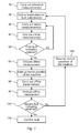
- the first set of values is further analysed at a fourth step 40 where the first set of values is first transformed into a frequency domain and then the current amplitudes at the side frequencies 140 are compared with the previously defined first threshold value 150 (cf. figure 2 ). If none of the current amplitudes at the side frequencies 140 exceeds the first threshold value 150, then no first fault indication at a fifth step 50 is obtained, and a new online measurement at the third step 30 is carried out after a predefined time delay. If at least one of the current amplitudes at the side frequencies 140 does exceed the first threshold value 150, then a first fault indication at the fifth step 50 is obtained, and as a consequence an offline measurement is applied.
- corresponding online measurements as described above for the broken rotor bar are carried out 30 and analysed 40 for all types of faults to be detected.
- the online measurements are not limited to phase current measurements in a stator winding, but may also include vibration measurements, phase voltage measurements, speed measurements, etc. If a first fault indication is obtained as a result of any of the online measurements and the subsequent analyses, an offline measurement is applied.
- an appropriate offline measurement is chosen from a plurality of alternative measurements. The choice is based on the type of the first fault indication.
- the first fault indication indicates a broken rotor bar
- a resistance measurement measuring responses to an injected test signal is chosen to determine the presence of the alleged broken rotor bar. Because of the requirements of the chosen measurement the normal operation of the motor is interrupted at a seventh step 70 by bringing the motor to standstill.
- a corresponding test signal as that explained above is injected in the motor, and a measurement on a response to the test signal is carried out to find out resistance at different electrical angles of the motor.
- a second set of values corresponding to the resistance curves 160, 170, 180, 190 as shown in figure 3 is obtained from this offline measurement.
- the second set of values is further analysed at a ninth step 90 where it is compared with the previously defined second threshold value 200. If none of the resistance values exceeds the second threshold value 200, then no second fault indication at a tenth step 100 is obtained, and the normal operation of the motor is resumed at a twelfth step 120.
- the condition of obtaining the first fault indication is changed by increasing the first threshold value 150 at the second step 20 to prevent another false alarm from being triggered. If at least one of the resistance values does exceed the second threshold value 200, then a second fault indication at the tenth step 100 is obtained. As a consequence of obtaining the second fault indication, the fault is confirmed at an eleventh step 110 and it is determined that the fault is present.
- the first fault indication would indicate another type of fault than a broken rotor bar, such as for example an inter-turn short circuit in a stator winding
- an indication of an inter-turn short circuit in a stator winding can be obtained with an online measurement measuring stator phase current and a subsequent analysis wherein the entity to be observed is current amplitude in time domain (unbalance between current amplitudes in different phases indicates a stator inter-turn fault).
- an online measurement according to EP2541217A1 can be used.
- an appropriate offline measurement capable of detecting that fault is chosen at the step 60.
- the offline measurement used to determine the presence of the alleged inter-turn short circuit in a stator winding may include measuring current responses to a 50 Hz test signal of 15 V voltage injected in the motor at different electrical angles of the stator winding when the motor is at standstill.
- the entity to be observed is an amplitude of the generated current. If the measured values deviate from the corresponding reference measurements and if a corresponding predefined threshold value is undershot (the current amplitude decreases when this type of fault is present), then the inter-turn short circuit in a stator winding can be confirmed.
- the offline measurement does not need to be carried out when the machine is at standstill.
- the offline measurement can also be carried out when the machine is at quasi standstill, is executing a certain speed ramp, or is executing any other movement that is not considered as normal operation of the machine.
- the machine is to be considered to assume normal operation when it rotates fast enough to fulfil its primary function in an installation it is connected to.
- the frequency converter preferably comprises a measuring instrument or measuring instruments for carrying out 30, 80 the different measurements, a test signal injecting means for injecting the test signal, and enough computing power for analysing 40, 90 the measurement results. Furthermore, the frequency converter preferably comprises a display means or another suitable means for informing an operator of the motor about an eventual fault.
- the invention is not limited to the embodiments shown above, but the person skilled in the art may modify them in a plurality of ways within the scope of the invention as defined by the claims.
- the invention is not limited to induction motors, but may also be applied to other types of electrical motors and also other types of electrical machines such as generators.
Landscapes
- Physics & Mathematics (AREA)
- General Physics & Mathematics (AREA)
- Engineering & Computer Science (AREA)
- Power Engineering (AREA)
- Tests Of Circuit Breakers, Generators, And Electric Motors (AREA)
Abstract
Description
- The present invention relates to a non-invasive method for detecting a fault in an electrical machine.
- Condition of electrical machines is many times monitored in order to prevent unexpected failures. There is a plurality of monitoring methods that can be divided into different categories depending on how they are executed. Depending on whether the machine needs to be opened or not, the methods can be divided into invasive and non-invasive methods. The methods can further be divided into online and offline methods (depending on whether the normal operation of the machine needs to interrupted for the monitoring), and continuous and non-continuous methods. An ideal monitoring method would be a non-invasive and continuous online method that is based on an easily measurable physical phenomenon and can detect in a reliable way all thinkable faults. However, depending on the fault, the available methods can be far from the ideal. For example, even when a non-invasive online method exists, the results may require lots of interpretation and the reliability may be worse than desired.
-
WO201245353A1 EP2518456A1 discloses a method for monitoring demagnetization of permanent magnets in a synchronous machine.EP2541217A1 discloses a method for identifying the following faults in an electrical machine: a broken rotor bar, a dynamic eccentricity, a static eccentricity, an inter-turn short circuit and an inter-coil short circuit. All the methods disclosed in the aforementioned patent applications are non-invasive methods that can be applied continuously online. However, depending on the machine type, on the normal operation conditions of the machine, and on the threshold values that are chosen to indicate a fault, the respective method may not always give reliable results. As a consequence, false alarms can be triggered, or, if the threshold values are increased to avoid false alarms, a fault can go undetected. There thus remains a desire to improve the reliability of the existing fault detection methods in electrical machines. - One object of the invention is to provide an improved method for detecting a fault in an electrical machine. The improved method shall be more reliable than the previously known methods.
- This object is achieved by the method according to the appended claim 1, and by the frequency converter according to the appended claim 13.
- The invention is based on the realization that a fault indication obtained with a less reliable but a convenient method can be confirmed by applying a more reliable but a less convenient method. The combination of the two methods results in a reliable method with a good ability to detect faults without triggering too many false alarms.
- According to a first aspect of the invention, there is provided a method for detecting a fault in an electrical machine. The method comprises the steps of: carrying out at least one first measurement on the machine during a normal operation of the machine to obtain a first set of values; analysing the first set of values to obtain a first fault indication; interrupting, as a consequence of obtaining the first fault indication, the normal operation of the machine; choosing, on the basis of the type of the first fault indication, a second measurement from a plurality of alternative measurements; carrying out the second measurement on the machine when the normal operation of the machine is interrupted to obtain a second set of values; analysing the second set of values to obtain a second fault indication; and determining, on the basis of whether the second fault indication is obtained or not, whether the fault is present or not. The combination of the first and the second fault indications enables detecting faults reliably without triggering too many false alarms.
- According to one embodiment of the invention, the method further comprises the steps of: resuming, as a consequence of not obtaining the second fault indication, the normal operation of the machine; and changing a condition of obtaining the first fault indication. By this measure the influence of the false alarm on an installation the machine is connected to is minimized and another false alarm is prevented from being triggered.
- According to one embodiment of the invention, the first measurement comprises one of the following: a phase current measurement in a stator winding, a vibration measurement, a phase voltage measurement and a speed measurement. These measurements are found out to be convenient online measurements providing first indications of different types of faults.
- According to one embodiment of the invention, the fault is one of the following: an inter-turn short circuit in a stator winding, a broken rotor bar, a bearing fault and a cooling fault. The present method is particularly well adapted to detect the named faults.
- According to one embodiment of the invention, the step of analysing of the first set of values comprises transformation of the first set of values into a frequency domain. Analysis in a frequency domain is particularly well adapted for online measurement results as many types of faults can be detected from current and vibration spectra during normal operation of the machine.
- According to one embodiment of the invention, the second measurement is carried out when the machine is at standstill. Measurement at standstill is particularly well adapted for confirming a fault as many of the most reliable analysing methods assume measurements done at standstill.
- According to one embodiment of the invention, the method further comprises the step of injecting a test signal in a winding of the machine, and the second set of values comprises a response to the test signal. Measuring a response on a test signal is particularly well adapted for confirming a fault as many of the most reliable analysing methods assume excitation of the stator winding.
- According to one embodiment of the invention, the method further comprises the step of carrying out a reference measurement on the machine when the machine is new or otherwise presumably fault free to obtain a set of reference values. By this measure access to reference values is ensured, which improves the reliability of the used analysing methods.
- According to one embodiment of the invention, the method further comprises the step of comparing the first set of values and/or the second set of values with the set of reference values. By this measure the reliability of the used analysing methods is improved.
- According to one embodiment of the invention, at least one method step is executed automatically by a computer program running within a frequency converter operating the machine. By this measure the fault detection can be rendered continuous without the need of interaction by an operator. According to one embodiment of the invention, the method further comprises the step of providing, as a consequence of obtaining the first fault indication, a first warning. By this measure the operator is informed about eventual problems with the machine.
- According to one embodiment of the invention, the method further comprises the step of providing, as a consequence of obtaining the second fault indication, a second warning. By this measure the operator is informed about apparent problems with the machine.
- According to a second aspect of the invention, there is provided a frequency converter for operating an electrical machine. The frequency converter comprises a computer program configured to execute the method steps of the method disclosed hereinbefore. By integrating the fault detection program within the frequency converter no additional hardware device is needed for executing the fault detection function.
- According to one embodiment of the invention, the frequency converter further comprises a measuring instrument for carrying out the first and/or the second measurement. By integrating the measuring instrument with the frequency converter no separate hardware device is needed for carrying out the measurements.
- According to one embodiment of the invention, the frequency converter further comprises means for injecting a test signal in a winding of the machine. By integrating the means for injecting the test signal with the frequency converter no separate hardware device is needed for carrying out the excitation of the winding.
- The invention will be explained in greater detail with reference to the accompanying drawings, wherein
- figure 1
- shows a flow chart illustrating one embodiment of the invention,
- figure 2
- shows a measurement result relating to obtaining a first fault indication, and
- figure 3
- shows a measurement result relating to obtaining a second fault indication.
- Referring to
figure 1 , a flow chart illustrating a method according to the present invention is shown. At a first step 10 a reference measurement or reference measurements for an electrical machine are carried out. For the sake of this example it can be assumed that the electrical machine is an induction motor, and that one type of a fault to be detected is a broken rotor bar. The reference measurements can comprise a phase current measurement in a stator winding carried out when the motor is new and operating at full load. The reference measurements can further comprise resistance measurements including measuring responses to an injected test signal. The test signal can comprise 10 Hz, 50 Hz and 100 HZ excitation signals injected at different electrical angles of the stator winding when the motor is at standstill. The voltage of the test signal can be chosen so that the stator current is about 20% of the rated current. The reference values obtained from the reference measurements are reflecting a response of a fault free motor. - At a
second step 20 conditions for obtaining fault indications are defined. Firstly, a first threshold value 150 (figure 2 ) which, when exceeded, triggers a first fault indication, is defined. In the present example the entity to be observed is an amplitude of a stator current at certain harmonic frequency that is known to indicate a broken rotor bar.Figure 2 shows a spectrum of a stator current measurement. The current has one fundamentalharmonic frequency 130 at the supply frequency of the motor. There are twoside frequencies 140 the existence of which indicates at least one broken rotor bar. Thefirst threshold value 150 is chosen appropriately on the basis of previous experiences about how broken rotor bars affect the current frequencies. For example, thefirst threshold value 150 can be chosen to be two times the corresponding value in a healthy machine on a decibel scale. For the purpose of frequency analysis according tofigure 2 the measured stator current values are brought into a frequency domain e.g. by using a Fourier transform. - Further at the
second step 20 offigure 1 , a second threshold value 200 (figure 3 ) for obtaining a second fault indication is defined. In the present example the entity to be observed is resistance at different electrical angles of the motor.Figure 3 shows experimental results of a measurement on a response to a corresponding test signal as that explained above. Thefirst resistance curve 160 represents a healthy motor, and the second, third and fourth resistance curves 170, 180, 190 represent motors with one, two and three broken rotor bars, respectively. Thesecond threshold value 200 is chosen appropriately on the basis of the experimental results on how broken rotor bars affect the resistance. For example, thesecond threshold value 200 can be chosen to be in the middle of the average value of thefirst resistance curve 160 and the maximum value of thesecond resistance curve 170. - Yet further at the
second step 20 offigure 1 , corresponding conditions for obtaining first and second fault indications as described above for the broken rotor bar are defined for all types of faults to be detected. Such other types of faults may include an inter-turn short circuit in a stator winding, a bearing fault and a cooling fault. - At a third step 30 a stator current measurement on the motor is carried out during a normal operation of the motor. A first set of values is obtained from this online measurement. The first set of values is further analysed at a
fourth step 40 where the first set of values is first transformed into a frequency domain and then the current amplitudes at theside frequencies 140 are compared with the previously defined first threshold value 150 (cf.figure 2 ). If none of the current amplitudes at theside frequencies 140 exceeds thefirst threshold value 150, then no first fault indication at afifth step 50 is obtained, and a new online measurement at thethird step 30 is carried out after a predefined time delay. If at least one of the current amplitudes at theside frequencies 140 does exceed thefirst threshold value 150, then a first fault indication at thefifth step 50 is obtained, and as a consequence an offline measurement is applied. - Again, corresponding online measurements as described above for the broken rotor bar are carried out 30 and analysed 40 for all types of faults to be detected. The online measurements are not limited to phase current measurements in a stator winding, but may also include vibration measurements, phase voltage measurements, speed measurements, etc. If a first fault indication is obtained as a result of any of the online measurements and the subsequent analyses, an offline measurement is applied.
- At a
sixth step 60 an appropriate offline measurement is chosen from a plurality of alternative measurements. The choice is based on the type of the first fault indication. In the present example (the first fault indication indicates a broken rotor bar) a resistance measurement measuring responses to an injected test signal is chosen to determine the presence of the alleged broken rotor bar. Because of the requirements of the chosen measurement the normal operation of the motor is interrupted at aseventh step 70 by bringing the motor to standstill. - At an eighth step 80 a corresponding test signal as that explained above is injected in the motor, and a measurement on a response to the test signal is carried out to find out resistance at different electrical angles of the motor. A second set of values corresponding to the resistance curves 160, 170, 180, 190 as shown in
figure 3 is obtained from this offline measurement. The second set of values is further analysed at aninth step 90 where it is compared with the previously definedsecond threshold value 200. If none of the resistance values exceeds thesecond threshold value 200, then no second fault indication at atenth step 100 is obtained, and the normal operation of the motor is resumed at atwelfth step 120. The condition of obtaining the first fault indication is changed by increasing thefirst threshold value 150 at thesecond step 20 to prevent another false alarm from being triggered. If at least one of the resistance values does exceed thesecond threshold value 200, then a second fault indication at thetenth step 100 is obtained. As a consequence of obtaining the second fault indication, the fault is confirmed at aneleventh step 110 and it is determined that the fault is present. - If the first fault indication would indicate another type of fault than a broken rotor bar, such as for example an inter-turn short circuit in a stator winding, then eventually another offline measurement would be chosen. For example, an indication of an inter-turn short circuit in a stator winding can be obtained with an online measurement measuring stator phase current and a subsequent analysis wherein the entity to be observed is current amplitude in time domain (unbalance between current amplitudes in different phases indicates a stator inter-turn fault). Alternatively, an online measurement according to
EP2541217A1 can be used. According to the present invention, when a first fault indication indicating an inter-turn short circuit in a stator winding is obtained at thefifth step 50, an appropriate offline measurement capable of detecting that fault is chosen at thestep 60. In the present example the offline measurement used to determine the presence of the alleged inter-turn short circuit in a stator winding may include measuring current responses to a 50 Hz test signal of 15 V voltage injected in the motor at different electrical angles of the stator winding when the motor is at standstill. The entity to be observed is an amplitude of the generated current. If the measured values deviate from the corresponding reference measurements and if a corresponding predefined threshold value is undershot (the current amplitude decreases when this type of fault is present), then the inter-turn short circuit in a stator winding can be confirmed. - It can also happen that the offline measurement does not need to be carried out when the machine is at standstill. Depending on the requirements of chosen measurement, the offline measurement can also be carried out when the machine is at quasi standstill, is executing a certain speed ramp, or is executing any other movement that is not considered as normal operation of the machine. In the context of the present invention the machine is to be considered to assume normal operation when it rotates fast enough to fulfil its primary function in an installation it is connected to.
- All the above mentioned steps 10-120 can be executed automatically by a computer program running within a frequency converter operating the motor. The frequency converter preferably comprises a measuring instrument or measuring instruments for carrying out 30, 80 the different measurements, a test signal injecting means for injecting the test signal, and enough computing power for analysing 40, 90 the measurement results. Furthermore, the frequency converter preferably comprises a display means or another suitable means for informing an operator of the motor about an eventual fault.
- The invention is not limited to the embodiments shown above, but the person skilled in the art may modify them in a plurality of ways within the scope of the invention as defined by the claims. Thus, the invention is not limited to induction motors, but may also be applied to other types of electrical motors and also other types of electrical machines such as generators.
Claims (15)
- A method for detecting a fault in an electrical machine, the method comprising the steps of:- carrying out (30) at least one first measurement on the machine during a normal operation of the machine to obtain a first set of values;- analysing (40) the first set of values to obtain a first fault indication;- interrupting (70), as a consequence of obtaining the first fault indication, the normal operation of the machine;- choosing (60), on the basis of the type of the first fault indication, a second measurement from a plurality of alternative measurements;- carrying out (80) the second measurement on the machine when the normal operation of the machine is interrupted to obtain a second set of values;- analysing (90) the second set of values to obtain a second fault indication; and- determining, on the basis of whether the second fault indication is obtained or not, whether the fault is present or not.
- The method according to claim 1, the method further comprising the steps of:- resuming (120), as a consequence of not obtaining the second fault indication, the normal operation of the machine; and- changing (20) a condition (150) of obtaining the first fault indication.
- The method according to any of the preceding claims,
wherein the first measurement comprises one of the following: a phase current measurement in a stator winding, a vibration measurement, a phase voltage measurement and a speed measurement. - The method according to any of the preceding claims,
wherein the fault is one of the following: an inter-turn short circuit in a stator winding, a broken rotor bar, a bearing fault and a cooling fault. - The method according to any of the preceding claims,
wherein the step of analysing (40) of the first set of values comprises transformation of the first set of values into a frequency domain. - The method according to any of the preceding claims,
wherein the second measurement is carried out (80) when the machine is at standstill. - The method according to any of the preceding claims,
wherein the method further comprises the step of injecting a test signal in a winding of the machine, and the second set of values comprises a response to the test signal. - The method according to any of the preceding claims, the method further comprising the step of: carrying out (10) a reference measurement on the machine when the machine is new or otherwise presumably fault free to obtain a set of reference values.
- The method according to claim 8, the method further comprising the step of: comparing the first set of values and/or the second set of values with the set of reference values.
- The method according to any of the preceding claims,
wherein at least one method step is executed automatically by a computer program running within a frequency converter operating the machine. - The method according to any of the preceding claims, the method further comprising the step of: providing, as a consequence of obtaining the first fault indication, a first warning.
- The method according to any of the preceding claims, the method further comprising the step of: providing, as a consequence of obtaining the second fault indication, a second warning.
- A frequency converter for operating an electrical machine, characterized in that the frequency converter comprises a computer program configured to execute the method steps of at least one of the preceding claims.
- A frequency converter according to claim 13, further comprising a measuring instrument for carrying out the first and/or the second measurement.
- A frequency converter according to any of claims 13 and 14, further comprising means for injecting a test signal in a winding of the machine.
Priority Applications (1)
| Application Number | Priority Date | Filing Date | Title |
|---|---|---|---|
| EP13184962.2A EP2851698B1 (en) | 2013-09-18 | 2013-09-18 | A method for detecting a fault in an electrical machine |
Applications Claiming Priority (1)
| Application Number | Priority Date | Filing Date | Title |
|---|---|---|---|
| EP13184962.2A EP2851698B1 (en) | 2013-09-18 | 2013-09-18 | A method for detecting a fault in an electrical machine |
Publications (2)
| Publication Number | Publication Date |
|---|---|
| EP2851698A1 true EP2851698A1 (en) | 2015-03-25 |
| EP2851698B1 EP2851698B1 (en) | 2021-07-21 |
Family
ID=49212659
Family Applications (1)
| Application Number | Title | Priority Date | Filing Date |
|---|---|---|---|
| EP13184962.2A Active EP2851698B1 (en) | 2013-09-18 | 2013-09-18 | A method for detecting a fault in an electrical machine |
Country Status (1)
| Country | Link |
|---|---|
| EP (1) | EP2851698B1 (en) |
Cited By (6)
| Publication number | Priority date | Publication date | Assignee | Title |
|---|---|---|---|---|
| JP5985099B1 (en) * | 2016-03-31 | 2016-09-06 | 株式会社高田工業所 | Rotating machine system abnormality detection method, rotating machine system abnormality monitoring method using the abnormality detection method, and rotating machine system abnormality monitoring apparatus using the abnormality monitoring method |
| EP3181900A1 (en) * | 2015-11-26 | 2017-06-21 | Gamesa Innovation & Technology, S.L. | Methods and systems for real-time monitoring of the insulation state of wind-powered generator windings |
| EP3232562A1 (en) * | 2016-04-11 | 2017-10-18 | General Electric Company | Dynamoelectric machine fault monitoring system, computer program product and related methods |
| WO2018158910A1 (en) * | 2017-03-02 | 2018-09-07 | 株式会社日立製作所 | Diagnostic device and diagnostic method |
| WO2019101891A1 (en) * | 2017-11-24 | 2019-05-31 | Electricite De France | Method and device for diagnosing faults of an alternator |
| CN112671307A (en) * | 2020-12-25 | 2021-04-16 | 浙江理工大学 | Surface-mounted permanent magnet synchronous motor demagnetization degree evaluation method and device |
Citations (8)
| Publication number | Priority date | Publication date | Assignee | Title |
|---|---|---|---|---|
| EP1418655A2 (en) * | 2002-11-07 | 2004-05-12 | General Electric Company | Speed sensitive field ground detection mode for a generator field winding |
| DE202010000374U1 (en) * | 2009-04-01 | 2010-07-01 | Abb Oy | Arrangement for condition monitoring |
| US20110025371A1 (en) * | 2008-04-09 | 2011-02-03 | Danfoss Drives A/S | Method for detecting a fault in an induction machine |
| US20120001580A1 (en) * | 2010-07-01 | 2012-01-05 | Pinjia Zhang | System and method for detecting fault in an ac machine |
| WO2012045353A1 (en) | 2010-10-07 | 2012-04-12 | Abb Research Ltd | Detection of a missing stator slot wedge in an electrical machine |
| EP2518456A1 (en) | 2011-04-29 | 2012-10-31 | ABB Technology AG | Method for monitoring demagnetization |
| EP2541217A1 (en) | 2011-06-29 | 2013-01-02 | ABB Research Ltd. | A method for identifying a fault in an electrical machine |
| US20130030742A1 (en) * | 2011-07-28 | 2013-01-31 | Arijit Banerjee | Method and system for monitoring a synchronous machine |
Family Cites Families (1)
| Publication number | Priority date | Publication date | Assignee | Title |
|---|---|---|---|---|
| US6960918B2 (en) * | 2003-01-28 | 2005-11-01 | Delphi Technologies, Inc. | Method and apparatus for control and fault detection of a remote electrical motor |
-
2013
- 2013-09-18 EP EP13184962.2A patent/EP2851698B1/en active Active
Patent Citations (8)
| Publication number | Priority date | Publication date | Assignee | Title |
|---|---|---|---|---|
| EP1418655A2 (en) * | 2002-11-07 | 2004-05-12 | General Electric Company | Speed sensitive field ground detection mode for a generator field winding |
| US20110025371A1 (en) * | 2008-04-09 | 2011-02-03 | Danfoss Drives A/S | Method for detecting a fault in an induction machine |
| DE202010000374U1 (en) * | 2009-04-01 | 2010-07-01 | Abb Oy | Arrangement for condition monitoring |
| US20120001580A1 (en) * | 2010-07-01 | 2012-01-05 | Pinjia Zhang | System and method for detecting fault in an ac machine |
| WO2012045353A1 (en) | 2010-10-07 | 2012-04-12 | Abb Research Ltd | Detection of a missing stator slot wedge in an electrical machine |
| EP2518456A1 (en) | 2011-04-29 | 2012-10-31 | ABB Technology AG | Method for monitoring demagnetization |
| EP2541217A1 (en) | 2011-06-29 | 2013-01-02 | ABB Research Ltd. | A method for identifying a fault in an electrical machine |
| US20130030742A1 (en) * | 2011-07-28 | 2013-01-31 | Arijit Banerjee | Method and system for monitoring a synchronous machine |
Non-Patent Citations (3)
| Title |
|---|
| BYUNGHWAN KIM ET AL: "Automated Detection of Rotor Faults for Inverter-Fed Induction Machines Under Standstill Conditions", IEEE TRANSACTIONS ON INDUSTRY APPLICATIONS, IEEE SERVICE CENTER, PISCATAWAY, NJ, US, vol. 47, no. 1, 1 January 2011 (2011-01-01), pages 55 - 64, XP011342201, ISSN: 0093-9994, DOI: 10.1109/TIA.2010.2090931 * |
| GRUBIC S ET AL: "A survey of testing and monitoring methods for stator insulation systems in induction machines", CONDITION MONITORING AND DIAGNOSIS, 2008. CMD 2008. INTERNATIONAL CONFERENCE ON, IEEE, PISCATAWAY, NJ, USA, 21 April 2008 (2008-04-21), pages 196 - 203, XP031292477, ISBN: 978-1-4244-1621-9 * |
| JACK R. NICHOLAS: "Off-line and on-line motor electrical monitoring and condition analysis: payoffs and problems", PROCEEDINGS OF A JOINT CONFERENCE, MOBILE, ALABAMA, APRIL 22-26, 1996, 22 April 1996 (1996-04-22), pages 1 - 10, XP055104681, Retrieved from the Internet <URL:http://www.dtic.mil/dtic/tr/fulltext/u2/p010195.pdf> [retrieved on 20140227] * |
Cited By (11)
| Publication number | Priority date | Publication date | Assignee | Title |
|---|---|---|---|---|
| EP3181900A1 (en) * | 2015-11-26 | 2017-06-21 | Gamesa Innovation & Technology, S.L. | Methods and systems for real-time monitoring of the insulation state of wind-powered generator windings |
| CN107037331A (en) * | 2015-11-26 | 2017-08-11 | 歌美飒创新技术公司 | For the method and system for the state of insulation for monitoring wind-driven generator winding in real time |
| JP5985099B1 (en) * | 2016-03-31 | 2016-09-06 | 株式会社高田工業所 | Rotating machine system abnormality detection method, rotating machine system abnormality monitoring method using the abnormality detection method, and rotating machine system abnormality monitoring apparatus using the abnormality monitoring method |
| JP2017181437A (en) * | 2016-03-31 | 2017-10-05 | 株式会社高田工業所 | Rotary machine system abnormality detection method, rotary machine system abnormality monitoring method using abnormality detection method, and rotary machine system abnormality monitoring device using abnormality monitoring method |
| WO2017168796A1 (en) * | 2016-03-31 | 2017-10-05 | 株式会社高田工業所 | Abnormality detection method for rotary mechanical system, abnormality monitoring method for rotary mechanical system using said abnormality detection method, and abnormality monitoring device for rotary mechanical system using said abnormality detection method |
| EP3232562A1 (en) * | 2016-04-11 | 2017-10-18 | General Electric Company | Dynamoelectric machine fault monitoring system, computer program product and related methods |
| US10739405B2 (en) | 2016-04-11 | 2020-08-11 | General Electric Company | Dynamoelectric machine fault monitoring system, computer program product and related methods |
| WO2018158910A1 (en) * | 2017-03-02 | 2018-09-07 | 株式会社日立製作所 | Diagnostic device and diagnostic method |
| WO2019101891A1 (en) * | 2017-11-24 | 2019-05-31 | Electricite De France | Method and device for diagnosing faults of an alternator |
| FR3074300A1 (en) * | 2017-11-24 | 2019-05-31 | Electricite De France | METHOD AND DEVICE FOR FAULT DIAGNOSIS OF AN ALTERNATOR |
| CN112671307A (en) * | 2020-12-25 | 2021-04-16 | 浙江理工大学 | Surface-mounted permanent magnet synchronous motor demagnetization degree evaluation method and device |
Also Published As
| Publication number | Publication date |
|---|---|
| EP2851698B1 (en) | 2021-07-21 |
Similar Documents
| Publication | Publication Date | Title |
|---|---|---|
| US10267860B2 (en) | Fault detection in induction machines | |
| US8405339B2 (en) | System and method for detecting fault in an AC machine | |
| EP2851698B1 (en) | A method for detecting a fault in an electrical machine | |
| JP5792374B2 (en) | Method for monitoring demagnetization | |
| CA2847720C (en) | Broken rotor bar detection based on current signature analysis of an electric machine | |
| CN106304846B (en) | Method and system for determining fault status of synchronous machine | |
| US10408879B2 (en) | Method and apparatus for diagnosing a fault condition in an electric machine | |
| KR101326586B1 (en) | Apparatus and method for diagnosing rotor faults of induction motor, and a medium having computer readable program for executing the method | |
| Alwodai et al. | A comparison of different techniques for induction motor rotor fault diagnosis | |
| EP3054307A1 (en) | Stator fault detection and diagnosis | |
| EP2728367A1 (en) | A method for detecting a fault condition in an electrical machine | |
| JPWO2014156386A1 (en) | Diagnostic device and switching device for electric motor | |
| Goktas et al. | Separation of induction motor rotor faults and low frequency load oscillations through the radial leakage flux | |
| Noureddine et al. | Experimental exploitation for the diagnosis to the induction machine under a bearing fault-using MCSA | |
| Faiz et al. | A review of application of signal processing techniques for fault diagnosis of induction motors–Part I | |
| Oviedo et al. | Experimental evaluation of motor current signature and vibration analysis for rotor broken bars detection in an induction motor | |
| Gritli | Diagnosis and fault detection in electrical machines and drives based on advanced signal processing techniques | |
| Saad et al. | Fault diagnostics of induction motors based on internal flux measurement | |
| Bellini | Quad demodulation: A time-domain diagnostic method for induction machines | |
| Stojičić et al. | Monitoring of rotor bar faults in induction generators with full-size inverter | |
| Stankovic et al. | Enhanced algorithm for motor rotor broken bar detection | |
| Sharma et al. | Using motor current analysis for broken rotor bar fault detection in rotary machines | |
| Kral et al. | Condition monitoring and fault detection of electric drives | |
| Hwang et al. | Analysis of a three phase induction motor under eccentricity condition | |
| KR102152695B1 (en) | Apparatus and method of detecting field winding short circuits in 3-phase wound-field synchronous motors |
Legal Events
| Date | Code | Title | Description |
|---|---|---|---|
| PUAI | Public reference made under article 153(3) epc to a published international application that has entered the european phase |
Free format text: ORIGINAL CODE: 0009012 |
|
| 17P | Request for examination filed |
Effective date: 20130918 |
|
| AK | Designated contracting states |
Kind code of ref document: A1 Designated state(s): AL AT BE BG CH CY CZ DE DK EE ES FI FR GB GR HR HU IE IS IT LI LT LU LV MC MK MT NL NO PL PT RO RS SE SI SK SM TR |
|
| AX | Request for extension of the european patent |
Extension state: BA ME |
|
| RBV | Designated contracting states (corrected) |
Designated state(s): AL AT BE BG CH CY CZ DE DK EE ES FI FR GB GR HR HU IE IS IT LI LT LU LV MC MK MT NL NO PL PT RO RS SE SI SK SM TR |
|
| RAP1 | Party data changed (applicant data changed or rights of an application transferred) |
Owner name: ABB SCHWEIZ AG |
|
| STAA | Information on the status of an ep patent application or granted ep patent |
Free format text: STATUS: EXAMINATION IS IN PROGRESS |
|
| STAA | Information on the status of an ep patent application or granted ep patent |
Free format text: STATUS: EXAMINATION IS IN PROGRESS |
|
| GRAP | Despatch of communication of intention to grant a patent |
Free format text: ORIGINAL CODE: EPIDOSNIGR1 |
|
| STAA | Information on the status of an ep patent application or granted ep patent |
Free format text: STATUS: GRANT OF PATENT IS INTENDED |
|
| RIC1 | Information provided on ipc code assigned before grant |
Ipc: G01R 31/34 20200101AFI20210128BHEP Ipc: H02P 29/02 20160101ALN20210128BHEP Ipc: H02P 29/024 20160101ALI20210128BHEP |
|
| RIC1 | Information provided on ipc code assigned before grant |
Ipc: G01R 31/34 20200101AFI20210129BHEP Ipc: H02P 29/024 20160101ALI20210129BHEP Ipc: H02P 29/02 20160101ALN20210129BHEP |
|
| INTG | Intention to grant announced |
Effective date: 20210215 |
|
| RAP3 | Party data changed (applicant data changed or rights of an application transferred) |
Owner name: ABB SCHWEIZ AG |
|
| GRAS | Grant fee paid |
Free format text: ORIGINAL CODE: EPIDOSNIGR3 |
|
| GRAA | (expected) grant |
Free format text: ORIGINAL CODE: 0009210 |
|
| STAA | Information on the status of an ep patent application or granted ep patent |
Free format text: STATUS: THE PATENT HAS BEEN GRANTED |
|
| AK | Designated contracting states |
Kind code of ref document: B1 Designated state(s): AL AT BE BG CH CY CZ DE DK EE ES FI FR GB GR HR HU IE IS IT LI LT LU LV MC MK MT NL NO PL PT RO RS SE SI SK SM TR |
|
| REG | Reference to a national code |
Ref country code: GB Ref legal event code: FG4D |
|
| REG | Reference to a national code |
Ref country code: CH Ref legal event code: EP |
|
| REG | Reference to a national code |
Ref country code: DE Ref legal event code: R096 Ref document number: 602013078409 Country of ref document: DE |
|
| REG | Reference to a national code |
Ref country code: AT Ref legal event code: REF Ref document number: 1413057 Country of ref document: AT Kind code of ref document: T Effective date: 20210815 |
|
| REG | Reference to a national code |
Ref country code: IE Ref legal event code: FG4D |
|
| REG | Reference to a national code |
Ref country code: LT Ref legal event code: MG9D |
|
| REG | Reference to a national code |
Ref country code: NL Ref legal event code: MP Effective date: 20210721 |
|
| REG | Reference to a national code |
Ref country code: AT Ref legal event code: MK05 Ref document number: 1413057 Country of ref document: AT Kind code of ref document: T Effective date: 20210721 |
|
| PG25 | Lapsed in a contracting state [announced via postgrant information from national office to epo] |
Ref country code: HR Free format text: LAPSE BECAUSE OF FAILURE TO SUBMIT A TRANSLATION OF THE DESCRIPTION OR TO PAY THE FEE WITHIN THE PRESCRIBED TIME-LIMIT Effective date: 20210721 Ref country code: SE Free format text: LAPSE BECAUSE OF FAILURE TO SUBMIT A TRANSLATION OF THE DESCRIPTION OR TO PAY THE FEE WITHIN THE PRESCRIBED TIME-LIMIT Effective date: 20210721 Ref country code: FI Free format text: LAPSE BECAUSE OF FAILURE TO SUBMIT A TRANSLATION OF THE DESCRIPTION OR TO PAY THE FEE WITHIN THE PRESCRIBED TIME-LIMIT Effective date: 20210721 Ref country code: ES Free format text: LAPSE BECAUSE OF FAILURE TO SUBMIT A TRANSLATION OF THE DESCRIPTION OR TO PAY THE FEE WITHIN THE PRESCRIBED TIME-LIMIT Effective date: 20210721 Ref country code: NL Free format text: LAPSE BECAUSE OF FAILURE TO SUBMIT A TRANSLATION OF THE DESCRIPTION OR TO PAY THE FEE WITHIN THE PRESCRIBED TIME-LIMIT Effective date: 20210721 Ref country code: PT Free format text: LAPSE BECAUSE OF FAILURE TO SUBMIT A TRANSLATION OF THE DESCRIPTION OR TO PAY THE FEE WITHIN THE PRESCRIBED TIME-LIMIT Effective date: 20211122 Ref country code: NO Free format text: LAPSE BECAUSE OF FAILURE TO SUBMIT A TRANSLATION OF THE DESCRIPTION OR TO PAY THE FEE WITHIN THE PRESCRIBED TIME-LIMIT Effective date: 20211021 Ref country code: RS Free format text: LAPSE BECAUSE OF FAILURE TO SUBMIT A TRANSLATION OF THE DESCRIPTION OR TO PAY THE FEE WITHIN THE PRESCRIBED TIME-LIMIT Effective date: 20210721 Ref country code: LT Free format text: LAPSE BECAUSE OF FAILURE TO SUBMIT A TRANSLATION OF THE DESCRIPTION OR TO PAY THE FEE WITHIN THE PRESCRIBED TIME-LIMIT Effective date: 20210721 Ref country code: BG Free format text: LAPSE BECAUSE OF FAILURE TO SUBMIT A TRANSLATION OF THE DESCRIPTION OR TO PAY THE FEE WITHIN THE PRESCRIBED TIME-LIMIT Effective date: 20211021 Ref country code: AT Free format text: LAPSE BECAUSE OF FAILURE TO SUBMIT A TRANSLATION OF THE DESCRIPTION OR TO PAY THE FEE WITHIN THE PRESCRIBED TIME-LIMIT Effective date: 20210721 |
|
| PG25 | Lapsed in a contracting state [announced via postgrant information from national office to epo] |
Ref country code: PL Free format text: LAPSE BECAUSE OF FAILURE TO SUBMIT A TRANSLATION OF THE DESCRIPTION OR TO PAY THE FEE WITHIN THE PRESCRIBED TIME-LIMIT Effective date: 20210721 Ref country code: LV Free format text: LAPSE BECAUSE OF FAILURE TO SUBMIT A TRANSLATION OF THE DESCRIPTION OR TO PAY THE FEE WITHIN THE PRESCRIBED TIME-LIMIT Effective date: 20210721 Ref country code: GR Free format text: LAPSE BECAUSE OF FAILURE TO SUBMIT A TRANSLATION OF THE DESCRIPTION OR TO PAY THE FEE WITHIN THE PRESCRIBED TIME-LIMIT Effective date: 20211022 |
|
| REG | Reference to a national code |
Ref country code: DE Ref legal event code: R097 Ref document number: 602013078409 Country of ref document: DE |
|
| PG25 | Lapsed in a contracting state [announced via postgrant information from national office to epo] |
Ref country code: DK Free format text: LAPSE BECAUSE OF FAILURE TO SUBMIT A TRANSLATION OF THE DESCRIPTION OR TO PAY THE FEE WITHIN THE PRESCRIBED TIME-LIMIT Effective date: 20210721 |
|
| REG | Reference to a national code |
Ref country code: CH Ref legal event code: PL |
|
| REG | Reference to a national code |
Ref country code: BE Ref legal event code: MM Effective date: 20210930 |
|
| PLBE | No opposition filed within time limit |
Free format text: ORIGINAL CODE: 0009261 |
|
| STAA | Information on the status of an ep patent application or granted ep patent |
Free format text: STATUS: NO OPPOSITION FILED WITHIN TIME LIMIT |
|
| PG25 | Lapsed in a contracting state [announced via postgrant information from national office to epo] |
Ref country code: SM Free format text: LAPSE BECAUSE OF FAILURE TO SUBMIT A TRANSLATION OF THE DESCRIPTION OR TO PAY THE FEE WITHIN THE PRESCRIBED TIME-LIMIT Effective date: 20210721 Ref country code: SK Free format text: LAPSE BECAUSE OF FAILURE TO SUBMIT A TRANSLATION OF THE DESCRIPTION OR TO PAY THE FEE WITHIN THE PRESCRIBED TIME-LIMIT Effective date: 20210721 Ref country code: RO Free format text: LAPSE BECAUSE OF FAILURE TO SUBMIT A TRANSLATION OF THE DESCRIPTION OR TO PAY THE FEE WITHIN THE PRESCRIBED TIME-LIMIT Effective date: 20210721 Ref country code: MC Free format text: LAPSE BECAUSE OF FAILURE TO SUBMIT A TRANSLATION OF THE DESCRIPTION OR TO PAY THE FEE WITHIN THE PRESCRIBED TIME-LIMIT Effective date: 20210721 Ref country code: EE Free format text: LAPSE BECAUSE OF FAILURE TO SUBMIT A TRANSLATION OF THE DESCRIPTION OR TO PAY THE FEE WITHIN THE PRESCRIBED TIME-LIMIT Effective date: 20210721 Ref country code: CZ Free format text: LAPSE BECAUSE OF FAILURE TO SUBMIT A TRANSLATION OF THE DESCRIPTION OR TO PAY THE FEE WITHIN THE PRESCRIBED TIME-LIMIT Effective date: 20210721 Ref country code: AL Free format text: LAPSE BECAUSE OF FAILURE TO SUBMIT A TRANSLATION OF THE DESCRIPTION OR TO PAY THE FEE WITHIN THE PRESCRIBED TIME-LIMIT Effective date: 20210721 |
|
| 26N | No opposition filed |
Effective date: 20220422 |
|
| PG25 | Lapsed in a contracting state [announced via postgrant information from national office to epo] |
Ref country code: LU Free format text: LAPSE BECAUSE OF NON-PAYMENT OF DUE FEES Effective date: 20210918 Ref country code: IT Free format text: LAPSE BECAUSE OF FAILURE TO SUBMIT A TRANSLATION OF THE DESCRIPTION OR TO PAY THE FEE WITHIN THE PRESCRIBED TIME-LIMIT Effective date: 20210721 Ref country code: IE Free format text: LAPSE BECAUSE OF NON-PAYMENT OF DUE FEES Effective date: 20210918 Ref country code: BE Free format text: LAPSE BECAUSE OF NON-PAYMENT OF DUE FEES Effective date: 20210930 |
|
| PG25 | Lapsed in a contracting state [announced via postgrant information from national office to epo] |
Ref country code: LI Free format text: LAPSE BECAUSE OF NON-PAYMENT OF DUE FEES Effective date: 20210930 Ref country code: CH Free format text: LAPSE BECAUSE OF NON-PAYMENT OF DUE FEES Effective date: 20210930 |
|
| PG25 | Lapsed in a contracting state [announced via postgrant information from national office to epo] |
Ref country code: HU Free format text: LAPSE BECAUSE OF FAILURE TO SUBMIT A TRANSLATION OF THE DESCRIPTION OR TO PAY THE FEE WITHIN THE PRESCRIBED TIME-LIMIT; INVALID AB INITIO Effective date: 20130918 |
|
| PG25 | Lapsed in a contracting state [announced via postgrant information from national office to epo] |
Ref country code: CY Free format text: LAPSE BECAUSE OF FAILURE TO SUBMIT A TRANSLATION OF THE DESCRIPTION OR TO PAY THE FEE WITHIN THE PRESCRIBED TIME-LIMIT Effective date: 20210721 |
|
| PGFP | Annual fee paid to national office [announced via postgrant information from national office to epo] |
Ref country code: GB Payment date: 20230920 Year of fee payment: 11 |
|
| PGFP | Annual fee paid to national office [announced via postgrant information from national office to epo] |
Ref country code: FR Payment date: 20230928 Year of fee payment: 11 Ref country code: DE Payment date: 20230920 Year of fee payment: 11 |
|
| PG25 | Lapsed in a contracting state [announced via postgrant information from national office to epo] |
Ref country code: MK Free format text: LAPSE BECAUSE OF FAILURE TO SUBMIT A TRANSLATION OF THE DESCRIPTION OR TO PAY THE FEE WITHIN THE PRESCRIBED TIME-LIMIT Effective date: 20210721 |