EP2851692A1 - Insulation error detection system with branch-selective feed-in and selective isolation monitoring system, and method for determining a cross-link impedance between two subsystems - Google Patents
Insulation error detection system with branch-selective feed-in and selective isolation monitoring system, and method for determining a cross-link impedance between two subsystems Download PDFInfo
- Publication number
- EP2851692A1 EP2851692A1 EP20140177467 EP14177467A EP2851692A1 EP 2851692 A1 EP2851692 A1 EP 2851692A1 EP 20140177467 EP20140177467 EP 20140177467 EP 14177467 A EP14177467 A EP 14177467A EP 2851692 A1 EP2851692 A1 EP 2851692A1
- Authority
- EP
- European Patent Office
- Prior art keywords
- subsystem
- test signal
- insulation
- insulation fault
- subsystems
- Prior art date
- Legal status (The legal status is an assumption and is not a legal conclusion. Google has not performed a legal analysis and makes no representation as to the accuracy of the status listed.)
- Granted
Links
- 238000009413 insulation Methods 0.000 title claims abstract description 98
- 238000012544 monitoring process Methods 0.000 title claims abstract description 37
- 238000002955 isolation Methods 0.000 title claims abstract description 22
- 238000001514 detection method Methods 0.000 title claims abstract description 16
- 238000000034 method Methods 0.000 title claims abstract description 6
- 238000012360 testing method Methods 0.000 claims abstract description 101
- 230000000903 blocking effect Effects 0.000 claims abstract description 24
- 238000005259 measurement Methods 0.000 claims description 20
- 238000002347 injection Methods 0.000 claims description 2
- 239000007924 injection Substances 0.000 claims description 2
- 230000009977 dual effect Effects 0.000 abstract 1
- 238000012806 monitoring device Methods 0.000 description 10
- 239000004020 conductor Substances 0.000 description 9
- 238000013461 design Methods 0.000 description 3
- 230000000694 effects Effects 0.000 description 3
- 238000005538 encapsulation Methods 0.000 description 3
- 230000035945 sensitivity Effects 0.000 description 3
- 108010076504 Protein Sorting Signals Proteins 0.000 description 2
- 230000001419 dependent effect Effects 0.000 description 2
- 238000011156 evaluation Methods 0.000 description 2
- 239000000243 solution Substances 0.000 description 2
- 230000002411 adverse Effects 0.000 description 1
- 230000005540 biological transmission Effects 0.000 description 1
- 230000004807 localization Effects 0.000 description 1
- 238000000691 measurement method Methods 0.000 description 1
- 238000012986 modification Methods 0.000 description 1
- 230000004048 modification Effects 0.000 description 1
- 230000007935 neutral effect Effects 0.000 description 1
- 238000012545 processing Methods 0.000 description 1
- 230000001681 protective effect Effects 0.000 description 1
- 229920006395 saturated elastomer Polymers 0.000 description 1
- 238000011896 sensitive detection Methods 0.000 description 1
- 238000004088 simulation Methods 0.000 description 1
- 238000011144 upstream manufacturing Methods 0.000 description 1
Images


Classifications
-
- G—PHYSICS
- G01—MEASURING; TESTING
- G01R—MEASURING ELECTRIC VARIABLES; MEASURING MAGNETIC VARIABLES
- G01R31/00—Arrangements for testing electric properties; Arrangements for locating electric faults; Arrangements for electrical testing characterised by what is being tested not provided for elsewhere
- G01R31/12—Testing dielectric strength or breakdown voltage ; Testing or monitoring effectiveness or level of insulation, e.g. of a cable or of an apparatus, for example using partial discharge measurements; Electrostatic testing
- G01R31/14—Circuits therefor, e.g. for generating test voltages, sensing circuits
-
- G—PHYSICS
- G01—MEASURING; TESTING
- G01R—MEASURING ELECTRIC VARIABLES; MEASURING MAGNETIC VARIABLES
- G01R19/00—Arrangements for measuring currents or voltages or for indicating presence or sign thereof
- G01R19/0092—Arrangements for measuring currents or voltages or for indicating presence or sign thereof measuring current only
-
- G—PHYSICS
- G01—MEASURING; TESTING
- G01R—MEASURING ELECTRIC VARIABLES; MEASURING MAGNETIC VARIABLES
- G01R27/00—Arrangements for measuring resistance, reactance, impedance, or electric characteristics derived therefrom
- G01R27/02—Measuring real or complex resistance, reactance, impedance, or other two-pole characteristics derived therefrom, e.g. time constant
- G01R27/16—Measuring impedance of element or network through which a current is passing from another source, e.g. cable, power line
- G01R27/18—Measuring resistance to earth, i.e. line to ground
-
- G—PHYSICS
- G01—MEASURING; TESTING
- G01R—MEASURING ELECTRIC VARIABLES; MEASURING MAGNETIC VARIABLES
- G01R31/00—Arrangements for testing electric properties; Arrangements for locating electric faults; Arrangements for electrical testing characterised by what is being tested not provided for elsewhere
- G01R31/44—Testing lamps
-
- H—ELECTRICITY
- H02—GENERATION; CONVERSION OR DISTRIBUTION OF ELECTRIC POWER
- H02H—EMERGENCY PROTECTIVE CIRCUIT ARRANGEMENTS
- H02H3/00—Emergency protective circuit arrangements for automatic disconnection directly responsive to an undesired change from normal electric working condition with or without subsequent reconnection ; integrated protection
- H02H3/26—Emergency protective circuit arrangements for automatic disconnection directly responsive to an undesired change from normal electric working condition with or without subsequent reconnection ; integrated protection responsive to difference between voltages or between currents; responsive to phase angle between voltages or between currents
- H02H3/32—Emergency protective circuit arrangements for automatic disconnection directly responsive to an undesired change from normal electric working condition with or without subsequent reconnection ; integrated protection responsive to difference between voltages or between currents; responsive to phase angle between voltages or between currents involving comparison of the voltage or current values at corresponding points in different conductors of a single system, e.g. of currents in go and return conductors
- H02H3/33—Emergency protective circuit arrangements for automatic disconnection directly responsive to an undesired change from normal electric working condition with or without subsequent reconnection ; integrated protection responsive to difference between voltages or between currents; responsive to phase angle between voltages or between currents involving comparison of the voltage or current values at corresponding points in different conductors of a single system, e.g. of currents in go and return conductors using summation current transformers
- H02H3/334—Emergency protective circuit arrangements for automatic disconnection directly responsive to an undesired change from normal electric working condition with or without subsequent reconnection ; integrated protection responsive to difference between voltages or between currents; responsive to phase angle between voltages or between currents involving comparison of the voltage or current values at corresponding points in different conductors of a single system, e.g. of currents in go and return conductors using summation current transformers with means to produce an artificial unbalance for other protection or monitoring reasons or remote control
-
- G—PHYSICS
- G01—MEASURING; TESTING
- G01R—MEASURING ELECTRIC VARIABLES; MEASURING MAGNETIC VARIABLES
- G01R31/00—Arrangements for testing electric properties; Arrangements for locating electric faults; Arrangements for electrical testing characterised by what is being tested not provided for elsewhere
- G01R31/08—Locating faults in cables, transmission lines, or networks
-
- H—ELECTRICITY
- H02—GENERATION; CONVERSION OR DISTRIBUTION OF ELECTRIC POWER
- H02H—EMERGENCY PROTECTIVE CIRCUIT ARRANGEMENTS
- H02H7/00—Emergency protective circuit arrangements specially adapted for specific types of electric machines or apparatus or for sectionalised protection of cable or line systems, and effecting automatic switching in the event of an undesired change from normal working conditions
- H02H7/26—Sectionalised protection of cable or line systems, e.g. for disconnecting a section on which a short-circuit, earth fault, or arc discharge has occured
Definitions
- the invention relates to an insulation fault location system for a branched IT system with a subsystem (subnet) and with a differential current measuring device arranged in the subsystem for detecting a differential current measurement signal.
- the invention further comprises an insulation monitoring system for monitoring an insulation resistance in a branched IT system with a subsystem and with the features of the insulation fault location system and a method for determining a cross connection impedance between two subsystems in a branched IT system with the insulation monitoring system according to the invention.
- an active conductor may have an insulation fault without the current operation of the System must be interrupted, because due to the ideally infinitely large impedance value between the conductor and earth in this first error case can not form a closed circuit.
- An insulation fault is understood to be a faulty state of the IT system, which leads to a decrease in the insulation resistance below the permissible level of insulation.
- insulation fault location Along with the continuous insulation monitoring, a quick and reliable localization and removal of the insulation fault (insulation fault location) is essential.
- test current test current
- test current test current
- This test current signal can be detected by all measuring current transformers in this circuit.
- the aim of using an insulation fault location system in branched IT systems is the most sensitive detection of existing insulation faults in the subsystems and the determination of the subsystem with the largest insulation fault, ie the smallest insulation fault resistance. Since the test signal generator is almost always carried out with current limitation, the test current is divided between all the insulation fault resistances present in the IT system and the system leakage capacitances. The fault current flowing in a subnet is therefore not only dependent on the size of the fault resistance in this subnet, but also on further fault resistances and system leakage capacitances present in the IT system.
- the respective differential current measuring device in the subnet can only reliably detect insulation faults in the subnet to be monitored from a minimum residual current determined by the resolution and the measuring error of the measuring system. Therefore, the sensitivity of the isolation fault detection system is determined by the overall configuration of the IT system and can be adversely affected.
- the test signal is additionally dependent on the nominal voltage of the IT system to be monitored. Again, this is another parameter that affects the sensitivity of the isolation fault location system and increases the complexity of the isolation error search.
- Another peculiarity arises in insulation fault location systems, which feed pulse-shaped test signals, primarily in the form of a rectangular signal sequence, into the IT system.
- the transients must be taken into account by distributing existing system leakage capacitances.
- the ratio of the system leakage capacitance before and after the differential current measuring device in the subnet additionally determines the achievable sensitivity of the insulation fault location device.
- the problem with continuous insulation monitoring is that, according to the current state of the art, it is not possible to actively monitor the IT system of more than one insulation monitoring device at the same time.
- the active measuring systems of two or more active insulation monitoring devices in an IT system could influence each other in such a way that the monitoring task is not reliably guaranteed. Since the conductance of the parallel connection of all complex-valued insulation resistances in the overall system is always evaluated, the insulation monitoring device thus sees all existing system leakage capacitances in the IT system, the insulation monitoring device measuring system must be designed so that it can counteract the interference influences generated by the subsystems.
- the selective monitoring of IT subsystems is required in such a way that an insulation fault in an IT subsystem should lead to rapid shutdown of the affected subsystem and without influencing other IT subsystems.
- the present invention is therefore based on the object of designing an insulation fault location device which enables fast and reliable detection of insulation faults in a branched, multi-subsystem IT system. Furthermore, the object is to design for a branched IT system, an insulation monitoring device that allows fast and reliable monitoring of the entire isolation state of the IT system. Furthermore, a method is desirable, which provides more information on the isolation state of the IT system in addition to the determination of the insulation resistance.
- This object is related to the isolation error search in conjunction with the preamble of claim 1, characterized in that in the subsystem, a test signal generator for the serial feed of a test signal is arranged and that the subsystem has a blocking device, the effectiveness of the fed into this subsystem test signal on this Subsystem limited.
- an isolation fault search optimized for the respective subsystem can be carried out in conjunction with the differential current measuring device likewise present in each subsystem. Unaffected by the electrical state of the rest of the IT system, a fast and reliable detection of insulation faults is thus possible.
- the metrological interpretation of the Insulation fault location system is thus designed so that the electrical characteristics of each subsystem can be taken into account.
- the measurement and monitoring cycles can be adapted to the respective subsystem and freely set independently of the other subsystems.
- a test signal may be fed in at shorter intervals and a very fast measurement can be realized.
- robust, low-interference subsystems e.g. can be worked with larger fürsignalamplituden
- sensitive subsystems advantageously lower test signal amplitudes can be selected.
- test signal amplitude and test signal frequency can be optimally adapted to the conditions (network leakage capacitance, disturbances) of the subsystem to be monitored without influencing the measurement task in other subsystems.
- the blocking device thus prevents a reaction of the optimized for the respective subsystem test signal to the rest of the IT system.
- isolation fault detection system Due to the isolation fault detection system with two-selective, serial impression of a test signal in each subnet separately, while the effectiveness of the impressed test signal on the relevant subnetwork is largely limited by the blocking device, a reliable and fast isolation fault search can be carried out in the overall system.
- test signal generator is designed to generate test signals having a different waveform and adjustable signal parameters.
- Each test signal generator thus allows an individual, adapted to the electrical properties of the respective subsystem generation and feeding of a test signal optimally suitable for the respective subsystem. It is thus possible to make the test signal form, further test signal parameters and the associated evaluation methods adjustable and freely selectable in order to be able to realize the most robust possible detection of the insulation faults in the entire IT system. Furthermore, this embodiment of the investigasignalgenerators offers the possibility of sequential switching to different test signals to meet other measurement and monitoring tasks. By way of example, the multiple measurement with different test signals for the selective determination of leakage-current leading cross-connections between two subsystems may be mentioned here.
- test signal generator is designed as a sine signal generator or as a pulse signal generator.
- the blocking device has an adjustable selectivity which determines the strength of the limitation of the effectiveness of the test signal.
- This adjustable test signal selectivity can be used to determine how much the test signal of the blocking device is to be decoupled from the rest of the power supply network in a considered subsystem. This can be done for example by a Modification and presetting of the effective at the test signal frequency impedance of the blocking device done.
- the blocking device is designed as a series resonant circuit. Based on the electrical properties of the IT system as well as the expected interference and thus depending on the scholarsignalform the blocking device in the case of a sinusoidal test signal from a passive series resonant circuit whose resonant frequency corresponds to the frequency of the injected test signal and by his in the case of resonance by the ohmic resistance certain minimum impedance causes only a small part of the test current flows into the rest of the "preceding" IT system.
- the blocking device is advantageously designed as a comb filter.
- the active comb filter effects a low-resistance connection to ground potential for the respective test signal components of the relevant subsystem and prevents the rest of the IT system from being influenced by the test signal.
- test signal is designed as a serial feed of a common-mode signal.
- the test signal is superimposed on all active conductors of the subnet with the same phase.
- the object is achieved in conjunction with the characteristics of the insulation fault location system according to claims 1 to 8, characterized in that the subsystem has a selective decoupling device, which occurs when an insulation fault in a subsystem This subsystem is metrologically decoupled from the rest of the IT system and thus prevents an influence on the measurements in the rest of the IT system.
- the isolation fault detection system can be extended to a selective isolation monitoring system.
- the test current generated in the respective test current generator and fed in series into the subsystem can be configured as a measuring current for the insulation monitoring.
- this measuring current is not measured at the measuring resistor of an insulation monitoring device, but, like the test current mentioned above, is likewise detected by the differential current measuring device of the respective subsystem.
- the insulation monitoring system has the decoupling device in addition to the features of the insulation fault location system.
- the selective decoupling device With regard to the actual supply task, that is to say at the operating system frequency of the IT system to be monitored, the selective decoupling device must as far as possible behave like a low-resistance line resistance so as not to impair the intended operation of the IT system, e.g. the energy supply of the affected branch, inadmissible influence. With the aid of the selective decoupling device, it is also possible to simultaneously monitor existing high-impedance, error-free subsystems in the event of a low-resistance insulation fault in a subsystem.
- the claimed insulation monitoring system can be used both in ungrounded and in grounded systems.
- a parallel insulation monitoring in different subsystems is possible.
- the insulation monitoring system according to the invention can be optimally adapted to the conditions of the individual subsystem. Lying e.g. In a subsystem only low leakage capacitances before, so the isolation monitoring for this subnet can deliver results very quickly, even if there are very large network leakage capacity in other subnets. This also solves the problem of selectively acting insulation monitoring. A second error can thus be reliably detected.
- the selective decoupling device has an adjustable selectivity, which determines the degree of decoupling.
- a sufficiently high-impedance impedance is generated in the selective decoupling device for the test signals.
- the faulty branch for the test signals of the rest of the network therefore represents a high-impedance impedance.
- This impedance is, for example, with regard to its frequency dependence to the respective measuring system. and monitoring task customizable.
- the decoupling device must be sufficiently low-impedance in order not to unduly influence the intended operation of the entire IT system.
- the decoupling device when a sinusoidal test signal is fed in, is preferably designed as a parallel resonant circuit.
- This embodiment makes it possible to generate a high-impedance impedance at exactly the resonant frequency of the parallel resonant circuit, which corresponds to the frequency of the injected sinusoidal test signal.
- the object is achieved in that the two subsystems in a sequential multiple measurement first with the same test signal at the same setting the selectivity of the blocking device and the Decoupling device are acted upon, are subsequently acted upon with different test signals at different settings of the selectivities and the cross-connection impedance is determined from the difference of the measured insulation resistance values.
- two subsystems can first be operated respectively with the same test signal and the same settings of the test signal selectivities of the blocking device and the decoupling device, in a second step with different test signals and different test signal selectivities and in a third step, from a comparison of those in the steps one and two measured insulation resistance values are determined, the cross-connection impedance - wherein the order of the first two steps is interchangeable.
- test current components flow not only via possibly existing leakage impedances to earth but also over any existing cross-connections between the two subsystems.
- test signal components that are used in other subsystems are shielded for the subsystem considered, so that cross-connections to other subsystems have little influence on the measurement of the insulation resistance in the considered subsystem.
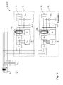
- the Fig. 1 shows the structure of a typical, corresponding to the prior art insulation fault location system for a branched IT system 4 with n subsystems (subnets) S 1 , .., S n .
- the IT system 4 is formed by way of example as a 3-phase power supply network with the outer conductors L 1 , L 2 , L 3 , the neutral conductor N and the protective conductor PE.
- the active conductors L 1 , L 2 , L 3 and N connect the current source 8 via a branched line system with the respective consumers V 1 , .., V n in the individual subsystems S 1 , .., S n .
- a test signal generator G for feeding a test signal is arranged in the main system.
- the test signal in the faulty subsystem S 1 ,..., S n of a differential current measuring device M 1 , .. , M n recorded and can then be evaluated in a central evaluation unit.
- the illustrated network configuration is further characterized by the system leakage capacitances C v and C n1 , .., C nn , where the distributed network leakage capacitances C v , C n1 , .., C nn are described here as lumped elements which precedes (C v ) and after (C n1 , .., C nn ) the differential current devices M 1 , .., M n are arranged.
- FIG. 2 An insulation fault location system 2 according to the invention with a branch-selective feed is shown.
- the insulation fault detection system 2 according to the invention for each subsystem S 1 , .., S n a test signal generator G 1 , .., G n for the serial feed of an individually to the electrical characteristics of the IT system 4, in particular the respective subsystem S 1 , .. , S n , tuned test signal.
- the test signal generator G 1 , .., G n serially feeds a common mode test signal into each subnet phase.
- This common mode test signal may be, for example, a sinusoidal 1V / 1 kHz test signal or a pulse signal.
- each subsystem S 1 , .., S n comprises a blocking device B 1 , .., B n , in order to prevent a reaction of the fed into the respective subsystem S 1 , .., S n test signal to the rest of the IT system.
- the blocking device B 1 ,..., B n concerned is preferably realized as a series resonant circuit with respect to earth with a resonance frequency of 1 kHz. Simulation results show that in a design of the series resonant circuit with an ohmic resistance of 100 mOhm and modeling the upstream network leakage capacity of 20 uF only approximately 1/80 of the 1 kHz test current from the subsystem S 1 , .., S n in the front of it flows.
- each subsystem S 1 , .., S n a suitable for detecting the test current differential current measuring device M 1 , .., M n arranged.
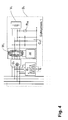
- FIG. 3 shows that in Fig. 2 illustrated isolation fault detection system 2, which has been extended by a decoupling device E 1 , .., E n arranged in each subsystem S 1 , .., S n and thus leads to the realization of a selective isolation monitoring system 12 according to the invention.
- a saturated ground fault occurs in a subsystem S 1 ,..., S n , ie, a subnet phase is connected to earth with negligible resistance
- the encapsulation of the individual subnets S 1 ,..., S n with the series resonant circuit of the blocking device B 1 .., B n against earth as a sole measure no longer be sufficiently effective.
- the encapsulation of the faulty subnet S 1 , .., S n is guaranteed even in this critical case.
- this additional decoupling provides additional measurement reliability, but is not necessary in principle.
- a decoupling device E 1 , .., E n in the form of a parallel resonant circuit, it is advantageous to use inductors coupled instead of single inductances.
- These "current-compensated chokes" provide a barely effective inductance component for the line-frequency (push-pull) load current, while the full inductance is effective for the test signal-frequency (common-mode) measuring current.
- the Fig. 4 shows an embodiment of a subnet S 1 , .., S n for pulse-shaped test signals.
- the blocking device B 1 is designed as an active comb filter which effects a low-impedance connection to ground potential only for the test signal components of the relevant subsystem S 1 ,..., S n .
Abstract
Die Erfindung betrifft ein Isolationsfehlersuchsystem mit zweigselektiver Einspeisung und ein selektives Isolationsüberwachungssystem für ein verzweigtes, aus mehreren Subsystemen bestehendes IT-System. Zur Isolationsfehlersuche sind in jedem Subsystem eine Differenzstrommesseinrichtung, ein Prüfsignalgenerator und eine Blockierungseinrichtung angeordnet. Das Isolationsüberwachungssystem umfasst zusätzlich eine in jedem Subsystem angeordnete selektive Entkopplungseinrichtung. Des Weiteren betrifft die Erfindung ein Verfahren zur Bestimmung einer Querimpedanz zwischen zwei Subsystemen auf der Basis des erfindungsgemäßen Isolationsüberwachungssystems.

Description
Die Erfindung betrifft ein Isolationsfehlersuchsystem für ein verzweigtes IT-System mit einem Subsystem (Subnetz) und mit einer in dem Subsystem angeordneten Differenzstrommesseinrichtung zur Erfassung eines Differenzstrom-Messsignals. Des Weiteren umfasst die Erfindung ein Isolationsüberwachungssystem zur Überwachung eines Isolationswiderstandes in einem verzweigten IT-System mit einem Subsystem und mit den Merkmalen des Isolationsfehlersuchsystems sowie ein Verfahren zur Bestimmung einer Querverbindungsimpedanz zwischen zwei Subsystemen in einem verzweigten IT-System mit dem erfindungsgemäßen Isolationsüberwachungssystem.The invention relates to an insulation fault location system for a branched IT system with a subsystem (subnet) and with a differential current measuring device arranged in the subsystem for detecting a differential current measurement signal. The invention further comprises an insulation monitoring system for monitoring an insulation resistance in a branched IT system with a subsystem and with the features of the insulation fault location system and a method for determining a cross connection impedance between two subsystems in a branched IT system with the insulation monitoring system according to the invention.
Um eine hohe Verfügbarkeit und Betriebssicherheit der elektrischen Stromversorgung sicherzustellen sowie die Personensicherheit im Aufenthaltsbereich elektrischer Anlagen zu gewährleisten, kommen in zunehmendem Maße Stromversorgungsnetze zum Einsatz, deren aktive Teile von dem Erdpotential getrennt sind. Bei dieser als IT-System bezeichneten Art des Stromversorgungsnetzes kann ein aktiver Leiter einen Isolationsfehler aufweisen, ohne dass der laufende Betrieb der Anlage unterbrochen werden muss, weil sich wegen des im Idealfall unendlich großen Impedanzwertes zwischen Leiter und Erde in diesem ersten Fehlerfall kein geschlossener Stromkreis ausbilden kann. Als Isolationsfehler wird dabei ein fehlerhafter Zustand des IT-Systems verstanden, der zum Absinken des Isolationswiderstands unter das zulässige Isolationsniveau führt. Aus dieser Betrachtung geht hervor, dass der Widerstand in dem zu überwachenden Netz gegen Erde (Isolationswiderstand - im Fehlerfall auch Fehlerwiderstand) ständig überwacht werden muss, da durch einen möglichen weiteren Fehler an einem anderen aktiven Leiter (zweiter Fehler) eine Fehlerschleife entstünde und der dabei fließende Fehlerstrom in Verbindung mit einer Überstrom-Schutzeinrichtung eine Abschaltung der Anlage mit Betriebsstillstand zur Folge hätte. Aus dem Stand der Technik bekannte aktiv messende Isolationsüberwachungsgeräte werden in dem Hauptzweig des IT-Systems zwischen den Netzleitern und Erde angeschlossen und überlagern dem Netz eine Messspannung, die zu einem dem Isolationswiderstand proportionalen Stromfluss führt. Dieser Messstrom verursacht an dem Messwiderstand des Isolationsüberwachungsgerätes einen Spannungsabfall, der ausgewertet wird und bei Überschreiten eines voreinstellbaren Grenzwertes eine Warnmeldung zur Folge hat.In order to ensure a high level of availability and reliability of the electrical power supply and to ensure personal safety in the area of residence of electrical systems, increasingly power supply networks are used whose active parts are separated from the ground potential. In this type of power supply system, referred to as an IT system, an active conductor may have an insulation fault without the current operation of the System must be interrupted, because due to the ideally infinitely large impedance value between the conductor and earth in this first error case can not form a closed circuit. An insulation fault is understood to be a faulty state of the IT system, which leads to a decrease in the insulation resistance below the permissible level of insulation. From this consideration, it is clear that the resistance in the network to be monitored against ground (insulation resistance - in the event of an error also fault resistance) must be constantly monitored, since a potential error on another active conductor (second error) would cause a fault loop and thereby flowing fault current in conjunction with an overcurrent protection device would result in a shutdown of the system with an operational standstill. Active measuring insulation monitoring devices known from the prior art are connected in the main branch of the IT system between the network conductors and earth and superimpose a measuring voltage on the network, which leads to a current flow proportional to the insulation resistance. This measuring current causes a voltage drop on the measuring resistor of the insulation monitoring device, which is evaluated and, if a presettable limit value is exceeded, results in a warning message.
Einhergehend mit der ständigen Isolationsüberwachung ist eine schnell und zuverlässig durchführbare Lokalisierung und Beseitigung des Isolationsfehlers (Isolationsfehlersuche) unerlässlich.Along with the continuous insulation monitoring, a quick and reliable localization and removal of the insulation fault (insulation fault location) is essential.
Tritt in einem IT-System ein Isolationsfehler auf, wird dieser von einem Isolationsüberwachungsgerät erkannt und gemeldet. Mit dieser Meldung startet die Isolationsfehlersuche, indem ein Prüfsignalgenerator ein Prüfsignal (Prüfstrom) erzeugt und dieses dem Stand der Technik gemäß an zentraler Stelle im Hauptzweig in das Stromversorgungssystem einspeist. Der Prüfstrom fließt dabei über die spannungsführenden Leitungen, den Fehlerwiderstand und die Erdleitung zu dem Prüfstromeinspeisepunkt zurück. Dieses Prüfstromsignal kann von allen Messstromwandlern, die in diesem Stromkreis liegen, erfasst werden.If an insulation fault occurs in an IT system, it is detected and reported by an insulation monitoring device. With this message, the insulation fault search starts by a test signal generator generates a test signal (test current) and feeds this according to the prior art in a central location in the main branch in the power supply system. The test current flows through the live cables, the fault resistance and the ground line to the test current infeed point back. This test current signal can be detected by all measuring current transformers in this circuit.
Das Ziel bei dem Einsatz eines Isolationsfehlersuchsystems in verzweigten IT-Systemen besteht in der möglichst empfindlichen Detektion vorhandener Isolationsfehler in den Subsystemen und in der Bestimmung des Subsystems mit dem größten Isolationsfehler, also dem kleinsten Isolationsfehlerwiderstand. Da der Prüfsignalgenerator praktisch immer strombegrenzt ausgeführt wird, erfolgt eine Stromteilung des Prüfstromes zwischen allen im IT-System vorhandenen Isolationsfehlerwiderständen und Netzableitkapazitäten. Der in einem Subnetz fließende Fehlerstrom ist also nicht nur abhängig von der Größe des Fehlerwiderstandes in diesem Subnetz, sondern auch von weiteren im IT-System vorhandenen Fehlerwiderständen und Netzableitkapazitäten. Die jeweilige Differenzstrommesseinrichtung in dem Subnetz kann erst ab einem von der Auflösung und dem Messfehler des Messsystems bestimmten minimalen Differenzstrom Isolationsfehler im zu überwachenden Subnetz sicher detektieren. Daher wird die Empfindlichkeit des Isolationsfehlersuchsystems von der Gesamtkonfiguration des IT -Systems bestimmt und kann negativ beeinträchtigt werden.The aim of using an insulation fault location system in branched IT systems is the most sensitive detection of existing insulation faults in the subsystems and the determination of the subsystem with the largest insulation fault, ie the smallest insulation fault resistance. Since the test signal generator is almost always carried out with current limitation, the test current is divided between all the insulation fault resistances present in the IT system and the system leakage capacitances. The fault current flowing in a subnet is therefore not only dependent on the size of the fault resistance in this subnet, but also on further fault resistances and system leakage capacitances present in the IT system. The respective differential current measuring device in the subnet can only reliably detect insulation faults in the subnet to be monitored from a minimum residual current determined by the resolution and the measuring error of the measuring system. Therefore, the sensitivity of the isolation fault detection system is determined by the overall configuration of the IT system and can be adversely affected.
Bei bekannten Ausführungen von Isolationsfehlersuchsystemen ist das Prüfsignal zusätzlich abhängig von der Nennspannung des zu überwachenden IT-Systems. Auch dies ist ein weiterer Parameter, welcher die Empfindlichkeit des Isolationsfehlersuchsystems beeinflusst und die Komplexität der Isolationsfehlersuche steigert. Eine weitere Besonderheit entsteht bei Isolationsfehlersuchsystemen, die impulsförmige Prüfsignale, vornehmlich in Form einer Rechtecksignalfolge, in das IT-System einspeisen. Hier müssen die Einschwingvorgänge durch verteilt vorhandene Netzableitkapazitäten beachtet werden. Das Verhältnis der Netzableitkapazitäten vor und nach der Differenzstrommesseinrichtung im Subnetz bestimmt zusätzlich die erreichbare Empfindlichkeit der Isolationsfehlersucheinrichtung.In known embodiments of insulation fault location systems, the test signal is additionally dependent on the nominal voltage of the IT system to be monitored. Again, this is another parameter that affects the sensitivity of the isolation fault location system and increases the complexity of the isolation error search. Another peculiarity arises in insulation fault location systems, which feed pulse-shaped test signals, primarily in the form of a rectangular signal sequence, into the IT system. Here, the transients must be taken into account by distributing existing system leakage capacitances. The ratio of the system leakage capacitance before and after the differential current measuring device in the subnet additionally determines the achievable sensitivity of the insulation fault location device.
Diese Überlegungen zeigen, dass der effiziente Einsatz eines Isolationsfehlersuchsystems die Kenntnis und Berücksichtigung der elektrischen Größen des gesamten IT-Systems voraussetzt. Auch die Kenntnis der Querverbindungsimpedanzen, also der komplexwertigen Ableitstrom-führenden Impedanzen zwischen den Subsystemen wäre von Vorteil.These considerations show that the efficient use of an insulation fault location system requires knowledge and consideration of the electrical quantities of the entire IT system. The knowledge of the cross-connection impedances, ie the complex-valued leakage current-carrying impedances between the subsystems, would also be advantageous.
Erschwert wird die Durchführung der Isolationsfehlersuche insbesondere in ausgedehnten, weitverzweigten IT-Systemen weiterhin dadurch, dass nicht immer eine Netzkonfiguration vorhanden ist, die eine hinreichend empfindliche Bestimmung von Isolationsfehlern in dem fehlerbehafteten Subnetz zulässt.The carrying out of the insulation fault location search, especially in extensive, widely branched IT systems, is further complicated by the fact that there is not always a network configuration which permits a sufficiently sensitive determination of insulation faults in the faulty subnetwork.
Neben diesen Schwierigkeiten bei der Isolationsfehlersuche tritt auch bei der ständigen Isolationsüberwachung das Problem auf, dass es nach dem derzeitigen Stand der Technik nicht möglich ist, das IT-System von mehr als einem Isolationsüberwachungsgerät gleichzeitig aktiv überwachen zu lassen. Die aktiven Messsysteme von zwei oder mehr aktiven Isolationsüberwachungsgeräten in einem IT-System könnten sich gegenseitig so beeinflussen, dass die Überwachungsaufgabe nicht zuverlässig gewährleistet ist. Da immer der Leitwert der Parallelschaltung aller komplexwertigen Isolationswiderstände im Gesamtsystem ausgewertet wird, das Isolationsüberwachungsgerät also alle vorhandenen Netzableitkapazitäten in dem IT-System sieht, muss das Messsystem des Isolationsüberwachungsgerätes so ausgelegt sein, dass es den durch die Subsysteme erzeugten Störeinflüssen begegnen kann. In einigen Applikationen wird die selektive Überwachung von IT-Subsystemen in der Weise gefordert, dass ein Isolationsfehler in einem IT-Subsystem zur schnellen Abschaltung des betroffenen Subsystems und ohne Beeinflussung anderer IT-Subsysteme führen soll. Mit Isolationsüberwachungssystemen nach dem Stand der Technik kann diese Forderung bislang nicht erfüllt werden.In addition to these difficulties in insulation fault location, the problem with continuous insulation monitoring is that, according to the current state of the art, it is not possible to actively monitor the IT system of more than one insulation monitoring device at the same time. The active measuring systems of two or more active insulation monitoring devices in an IT system could influence each other in such a way that the monitoring task is not reliably guaranteed. Since the conductance of the parallel connection of all complex-valued insulation resistances in the overall system is always evaluated, the insulation monitoring device thus sees all existing system leakage capacitances in the IT system, the insulation monitoring device measuring system must be designed so that it can counteract the interference influences generated by the subsystems. In some applications, the selective monitoring of IT subsystems is required in such a way that an insulation fault in an IT subsystem should lead to rapid shutdown of the affected subsystem and without influencing other IT subsystems. With insulation monitoring systems according to the prior art, this requirement can not be met so far.
Dort, wo eine selektive Isolationsüberwachung gefordert wird, bzw. bei der benötigten Reaktion auf einen kritischen zweiten Fehler im IT-System, wird versucht, mit dem Einsatz von richtungsselektiver Differenzstrommesstechnik bzw. auch in einfacher Weise mit Überstromauslösern brauchbare Lösungen zu realisieren. Diese Lösungen sind jedoch in IT-Systemen nur unter bestimmten Konfigurationen zuverlässig einsetzbar. Bei der richtungsselektiven Differenzstrommesstechnik ist z.B. das Verhältnis der Netzableitkapazitäten vor dem Summenstromwandler und der Netzableitkapazitäten nach dem Summenstromwandler entscheidend dafür, ob die richtungsselektive Messung zuverlässig funktioniert.Where selective isolation monitoring is required, or when the reaction to a critical second fault in the IT system is required, an attempt is made to use direction-sensitive differential current measurement technology or to realize useful solutions with overcurrent releases in a simple manner. However, these solutions can be used reliably in IT systems only under certain configurations. In the direction-selective differential current measurement technique, for example, the ratio of the system leakage capacitance before the summation current transformer and the system leakage capacitance after the summation current transformer determines whether the direction-selective measurement works reliably.
Der vorliegenden Erfindung liegt somit die Aufgabe zu Grunde, eine Isolationsfehlersucheinrichtung zu entwerfen, die eine schnelle und zuverlässige Detektion von Isolationsfehlern in einem verzweigten, mehrere Subsysteme umfassenden IT-System ermöglicht. Weiterhin besteht die Aufgabe darin, für ein verzweigtes IT-System eine Isolationsüberwachungseinrichtung zu entwerfen, die eine schnelle und zuverlässige Überwachung des gesamten Isolationszustandes des IT-Systems erlaubt. Weiterhin ist ein Verfahren erstrebenswert, das über die Bestimmung des Isolationswiderstandes hinaus weitere Informationen über den Isolationszustand des IT-Systems liefert.The present invention is therefore based on the object of designing an insulation fault location device which enables fast and reliable detection of insulation faults in a branched, multi-subsystem IT system. Furthermore, the object is to design for a branched IT system, an insulation monitoring device that allows fast and reliable monitoring of the entire isolation state of the IT system. Furthermore, a method is desirable, which provides more information on the isolation state of the IT system in addition to the determination of the insulation resistance.
Diese Aufgabe wird bezogen auf die Isolationsfehlersuche in Verbindung mit dem Oberbegriff des Anspruchs 1 dadurch gelöst, dass in dem Subsystem ein Prüfsignalgenerator zur seriellen Einspeisung eines Prüfsignals angeordnet ist und dass das Subsystem eine Blockierungseinrichtung aufweist, die die Wirksamkeit des in dieses Subsystem eingespeisten Prüfsignals auf dieses Subsystem begrenzt.This object is related to the isolation error search in conjunction with the preamble of
Indem für jedes Subsystem separat ein Prüfsignalgenerator sowie eine Blockierungseinrichtung vorgesehen sind, kann in Verbindung mit der ebenfalls in jedem Subsystem vorhandenen Differenzstrommesseinrichtung eine auf das jeweilige Subsystem optimierte Isolationsfehlersuche durchgeführt werden. Unbeeinflusst von dem elektrischen Zustand des übrigen IT-Systems ist somit eine schnelle und zuverlässige Detektion von Isolationsfehlern möglich. Die messtechnische Auslegung des Isolationsfehlersuchsystems ist damit so gestaltet, dass die elektrischen Kenngrößen jedes Subsystems berücksichtigt werden können.By separately providing a test signal generator and a blocking device for each subsystem, an isolation fault search optimized for the respective subsystem can be carried out in conjunction with the differential current measuring device likewise present in each subsystem. Unaffected by the electrical state of the rest of the IT system, a fast and reliable detection of insulation faults is thus possible. The metrological interpretation of the Insulation fault location system is thus designed so that the electrical characteristics of each subsystem can be taken into account.
Im Gegensatz zu aus dem Stand der Technik bekannten Isolationsfehlersuchsystemen können bei dem erfindungsgemäßen Isolationsfehlersuchsystem die Mess- und Überwachungszyklen auf das jeweilige Subsystem angepasst und unabhängig von den anderen Subsystemen frei eingestellt werden. In kritischen Subsystemen wird eventuell in kürzeren Abständen ein Prüfsignal eingespeist und eine sehr schnelle Messung realisiert. In robusten, wenig störanfälligen Subsystemen könnte z.B. mit größeren Prüfsignalamplituden gearbeitet werden, in sensiblen Subsystemen können vorteilhaft geringere Prüfsignalamplituden gewählt werden.In contrast to insulation fault location systems known from the prior art, with the insulation fault location system according to the invention, the measurement and monitoring cycles can be adapted to the respective subsystem and freely set independently of the other subsystems. In critical subsystems, a test signal may be fed in at shorter intervals and a very fast measurement can be realized. In robust, low-interference subsystems, e.g. can be worked with larger Prüfsignalamplituden, in sensitive subsystems advantageously lower test signal amplitudes can be selected.
Die Verwendung einer Blockierungseinrichtung und die damit verbundene gegenseitige Abkapselung der Messeinrichtungen in den Subsystemen führt vorteilhaft dazu, dass die einstellbaren Messparameter bzw. Prüfparameter wie z.B. Prüfsignalamplitude und Prüfsignalfrequenz optimal an die Gegebenheiten (Netzableitkapazität, Störungen) des zu überwachenden Subsystems angepasst werden können ohne die Messaufgabe in anderen Subsystemen zu beeinflussen.The use of a blocking device and the associated mutual encapsulation of the measuring devices in the subsystems advantageously leads to the adjustable measuring parameters or test parameters, such as, for example, Test signal amplitude and test signal frequency can be optimally adapted to the conditions (network leakage capacitance, disturbances) of the subsystem to be monitored without influencing the measurement task in other subsystems.
Die Blockierungseinrichtung verhindert somit eine Rückwirkung des für das jeweilige Subsystem optimierten Prüfsignals auf das übrige IT-System.The blocking device thus prevents a reaction of the optimized for the respective subsystem test signal to the rest of the IT system.
Durch das Isolationsfehlersuchsystem mit zweigselektiver, serieller Einprägung eines Prüfsignals in jedes Subnetz separat kann bei gleichzeitiger weitgehender Begrenzung der Wirksamkeit des eingeprägten Prüfsignals auf das betreffende Subnetz durch die Blockierungseinrichtung eine zuverlässige und schnelle Isolationsfehlersuche in dem Gesamtsystem erfolgen.Due to the isolation fault detection system with two-selective, serial impression of a test signal in each subnet separately, while the effectiveness of the impressed test signal on the relevant subnetwork is largely limited by the blocking device, a reliable and fast isolation fault search can be carried out in the overall system.
In weiterer vorteilhafter Ausgestaltung ist der Prüfsignalgenerator zur Erzeugung von Prüfsignalen ausgelegt, die eine unterschiedliche Signalform und einstellbare Signalparameter aufweisen.In a further advantageous embodiment of the test signal generator is designed to generate test signals having a different waveform and adjustable signal parameters.
Jeder Prüfsignalgenerator erlaubt somit eine individuelle, an die elektrischen Eigenschaften des betreffenden Subsystems angepasste Erzeugung und Einspeisung eines speziell für das jeweilige Subsystem optimal geeigneten Prüfsignals. So ist es möglich, die Prüfsignalform, weitere Prüfsignalparameter und die damit verbundenen Auswerteverfahren einstellbar zu gestalten und frei zu wählen, um eine möglichst robuste Detektion der Isolationsfehler in dem gesamten IT-System realisieren zu können. Weiterhin bietet diese Ausgestaltung des Prüfsignalgenerators die Möglichkeit der sequentiellen Umschaltung auf unterschiedliche Prüfsignale, um weiteren Mess- und Überwachungsaufgaben gerecht zu werden. Beispielhaft sei hier die Mehrfachmessung mit unterschiedlichen Prüfsignalen zur selektiven Bestimmung von Ableitstrom-führenden Querverbindungen zwischen zwei Subsystemen genannt.Each test signal generator thus allows an individual, adapted to the electrical properties of the respective subsystem generation and feeding of a test signal optimally suitable for the respective subsystem. It is thus possible to make the test signal form, further test signal parameters and the associated evaluation methods adjustable and freely selectable in order to be able to realize the most robust possible detection of the insulation faults in the entire IT system. Furthermore, this embodiment of the Prüfsignalgenerators offers the possibility of sequential switching to different test signals to meet other measurement and monitoring tasks. By way of example, the multiple measurement with different test signals for the selective determination of leakage-current leading cross-connections between two subsystems may be mentioned here.
In weiteren Ausgestaltungen ist der Prüfsignalgenerator als Sinus-Signalgenerator oder als Impuls-Signalgenerator ausgeführt.In further embodiments, the test signal generator is designed as a sine signal generator or as a pulse signal generator.
So kann in Abhängigkeit der elektrischen Kenngrößen wie beispielsweise den Netzableitkapazitäten des IT-Systems und im Hinblick auf die zu erwartenden Störeinflüsse die Einspeisung eines sinusförmigen Prüfsignals oder eines impulsförmigen Prüfsignals mit jeweils angepassten Prüfsignalparametern geeigneter erscheinen, um eine möglichst fehlerfreie Messung durchführen zu können.Thus, depending on the electrical characteristics such as the network leakage capacitances of the IT system and in view of the expected interference, the feeding of a sinusoidal test signal or a pulse-shaped test signal with respectively adapted Prüfsignalparametern appear more appropriate to perform the most error-free measurement can.
Vorteilhafterweise weist die Blockierungseinrichtung eine einstellbare Selektivität auf, die die Stärke der Begrenzung der Wirksamkeit des Prüfsignals bestimmt. Durch diese einstellbare Prüfsignalselektivität kann bestimmt werden, wie stark das Prüfsignal der Blockierungseinrichtung in einem betrachteten Subsystem von dem übrigen Stromversorgungsnetz abgekoppelt werden soll. Dies kann beispielsweise durch eine Veränderung und Voreinstellung der bei der Prüfsignalfrequenz wirksamen Impedanz der Blockierungseinrichtung erfolgen.Advantageously, the blocking device has an adjustable selectivity which determines the strength of the limitation of the effectiveness of the test signal. This adjustable test signal selectivity can be used to determine how much the test signal of the blocking device is to be decoupled from the rest of the power supply network in a considered subsystem. This can be done for example by a Modification and presetting of the effective at the test signal frequency impedance of the blocking device done.
Bevorzugt ist die Blockierungseinrichtung als Serienresonanzkreis ausgeführt. Ausgehend von den elektrischen Eigenschaften des IT-Systems sowie von den zu erwartenden Störungen und damit in Abhängigkeit der Prüfsignalform besteht die Blockierungseinrichtung im Fall eines sinusförmigen Prüfsignals aus einem passiven Serienresonanzkreis, dessen Resonanzfrequenz der Frequenz des eingespeisten Prüfsignals entspricht und der durch seine im Resonanzfall durch den ohmschen Widerstand bestimmte minimale Impedanz bewirkt, dass nur ein geringer Teil des Prüfstroms in das übrige "davorliegende" IT-System abfließt.Preferably, the blocking device is designed as a series resonant circuit. Based on the electrical properties of the IT system as well as the expected interference and thus depending on the Prüfsignalform the blocking device in the case of a sinusoidal test signal from a passive series resonant circuit whose resonant frequency corresponds to the frequency of the injected test signal and by his in the case of resonance by the ohmic resistance certain minimum impedance causes only a small part of the test current flows into the rest of the "preceding" IT system.
Im Fall eines impulsförmigen Prüfsignals, beispielsweise in Form einer Rechtecksignalfolge, ist die Blockierungseinrichtung vorteilhafterweise als Kammfilter ausgeführt. Das aktive Kammfilter bewirkt für die jeweiligen Prüfsignalanteile des betreffenden Subsystems eine niederohmige Verbindung mit Erdpotential und verhindert, dass das übrige IT-System durch das Prüfsignal beeinflusst wird.In the case of a pulse-shaped test signal, for example in the form of a rectangular signal sequence, the blocking device is advantageously designed as a comb filter. The active comb filter effects a low-resistance connection to ground potential for the respective test signal components of the relevant subsystem and prevents the rest of the IT system from being influenced by the test signal.
Weiterhin ist die Einspeisung des Prüfsignals als serielle Einspeisung eines Gleichtaktsignals ausgeführt. Dabei wird das Prüfsignal allen aktiven Leitern des Subnetzes mit gleicher Phase überlagert.Furthermore, the supply of the test signal is designed as a serial feed of a common-mode signal. The test signal is superimposed on all active conductors of the subnet with the same phase.
Bezogen auf die Isolationsüberwachung in einem verzweigten, aus mehreren Subsystemen bestehenden IT-System wird die Aufgabe in Verbindung mit den Merkmalen des Isolationsfehlersuchsystems nach den Ansprüchen 1 bis 8 dadurch gelöst, dass das Subsystem eine selektive Entkopplungseinrichtung aufweist, die bei Auftreten eines Isolationsfehlers in einem Subsystem dieses Subsystem von dem übrigen IT-System messtechnisch entkoppelt und damit eine Beeinflussung der Messungen in dem übrigen IT-System verhindert.Relative to the insulation monitoring in a branched, consisting of several subsystems IT system, the object is achieved in conjunction with the characteristics of the insulation fault location system according to
Basierend auf den vorgenannten Merkmalen kann das Isolationsfehlersuchsystem zu einem selektiven Isolationsüberwachungssystem erweitert werden. Der in dem jeweiligen Prüfstromgenerator erzeugte und seriell in das Subsystem eingespeiste Prüfstrom kann dabei als Messstrom für die Isolationsüberwachung konfiguriert werden. Dieser Messstrom wird im Gegensatz zur Verarbeitung in bekannten Isolationsüberwachungsgeräten nicht an dem Messwiderstand eines Isolationsüberwachungsgerätes gemessen, sondern wird wie der obengenannte Prüfstrom ebenfalls über die Differenzstrommesseinrichtung des jeweiligen Subsystems erfasst.Based on the aforementioned features, the isolation fault detection system can be extended to a selective isolation monitoring system. The test current generated in the respective test current generator and fed in series into the subsystem can be configured as a measuring current for the insulation monitoring. In contrast to processing in known insulation monitoring devices, this measuring current is not measured at the measuring resistor of an insulation monitoring device, but, like the test current mentioned above, is likewise detected by the differential current measuring device of the respective subsystem.
Damit ein in einem Subsystem auftretender Isolationsfehler nicht die Messungen in dem übrigen IT-System beeinflusst, weist das erfindungsgemäße Isolationsüberwachungssystem zusätzlich zu den Merkmalen des Isolationsfehlersuchsystems die Entkopplungseinrichtung auf.So that an insulation fault occurring in a subsystem does not affect the measurements in the rest of the IT system, the insulation monitoring system according to the invention has the decoupling device in addition to the features of the insulation fault location system.
Diese Maßnahme ist notwendig, um insbesondere bei einem Isolationsfehler mit einem Fehlerwiderstand nahe bei null Ohm (Erdschluss) in einem Subsystem keinen störendenden Einfluss auf die Mess- und Überwachungsaufgaben in dem übrigen Netzwerk zu erzeugen. Bezüglich der Mess- und Überwachungsaufgabe bleibt die Auswirkung des Isolationsfehlers somit auf das betroffene Subsystem beschränkt. Hinsichtlich der eigentlichen Versorgungsaufgabe, also bei Betriebs-Netzfrequenz des zu überwachenden IT-Systems muss sich die selektive Entkopplungseinrichtung möglichst wie ein niederohmiger Leitungswiderstand verhalten, um nicht den bestimmungsgemäßen Betrieb des IT-Systems, also z.B. die Energieversorgung des betroffenen Zweiges, unzulässig zu beeinflussen. Mit Hilfe der selektiven Entkopplungseinrichtung ist es möglich, bei einem niederohmigen Isolationsfehler in einem Subsystem gleichzeitig auch vorhandene weiterhin hochohmige, fehlerfreie Subsysteme zu überwachen.This measure is necessary, in particular in the case of an insulation fault with a fault resistance close to zero ohms (ground fault) in one subsystem, to produce no disruptive influence on the measurement and monitoring tasks in the rest of the network. With regard to the measuring and monitoring task, the effect of the insulation fault thus remains limited to the affected subsystem. With regard to the actual supply task, that is to say at the operating system frequency of the IT system to be monitored, the selective decoupling device must as far as possible behave like a low-resistance line resistance so as not to impair the intended operation of the IT system, e.g. the energy supply of the affected branch, inadmissible influence. With the aid of the selective decoupling device, it is also possible to simultaneously monitor existing high-impedance, error-free subsystems in the event of a low-resistance insulation fault in a subsystem.
Eine vollständige Begrenzung des Einflusses eines Isolationsfehlers in einem Subsystem auf das gesamte IT-System lässt sich allerdings nur dann erreichen, wenn das betroffene Subsystem im Fehlerfall gezielt abgeschaltet wird.However, it is only possible to completely limit the influence of an isolation error in a subsystem on the entire IT system then reach, if the affected subsystem is switched off in the event of an error.
Durch die erfindungsgemäße Ausgestaltung mit der selektiven Entkopplungseinrichtung lässt sich das beanspruchte Isolationsüberwachungssystem sowohl in ungeerdeten als auch in geerdeten Systemen einsetzen. Zudem ist eine parallele Isolationsüberwachung in verschiedenen Subsystemen möglich.Due to the configuration according to the invention with the selective decoupling device, the claimed insulation monitoring system can be used both in ungrounded and in grounded systems. In addition, a parallel insulation monitoring in different subsystems is possible.
Das erfindungsgemäße Isolationsüberwachungssystem kann optimal auf die Gegebenheiten des einzelnen Subsystems angepasst werden. Liegen z.B. in einem Subsystem nur geringe Netzableitkapazitäten vor, so kann die Isolationsüberwachung für dieses Subnetz sehr schnell Ergebnisse liefern, auch wenn in anderen Subnetzen sehr große Netzableitkapazitäten vorliegen. Damit wird auch das Problem einer selektiv wirkenden Isolationsüberwachung gelöst. Ein zweiter Fehler kann somit sicher erkannt werden.The insulation monitoring system according to the invention can be optimally adapted to the conditions of the individual subsystem. Lying e.g. In a subsystem only low leakage capacitances before, so the isolation monitoring for this subnet can deliver results very quickly, even if there are very large network leakage capacity in other subnets. This also solves the problem of selectively acting insulation monitoring. A second error can thus be reliably detected.
In weiterer vorteilhafter Ausgestaltung weist die selektive Entkopplungseinrichtung eine einstellbare Selektivität auf, die den Grad der Entkopplung bestimmt.In a further advantageous embodiment, the selective decoupling device has an adjustable selectivity, which determines the degree of decoupling.
Bevorzugt wird in der selektiven Entkopplungseinrichtung für die Prüfsignale eine hinreichend hochohmige Impedanz erzeugt. Um bei Auftreten eines Isolationsfehlers in einem Subsystem eine Beeinflussung der Messungen in dem übrigen IT-System weitgehend zu verhindern, stellt somit der fehlerhafte Zweig für die Prüfsignale des übrigen Netzwerks eine hochohmige Impedanz dar. Diese Impedanz ist beispielsweise hinsichtlich ihrer Frequenzabhängigkeit an die jeweilige Mess- und Überwachungsaufgabe anpassbar. Bei der Betriebs-Netzfrequenz muss die Entkopplungseinrichtung, wie oben bemerkt, hinreichend niederohmig sein, um den bestimmungsgemäßen Betrieb des gesamten IT-Systems nicht unzulässig zu beeinflussen.Preferably, a sufficiently high-impedance impedance is generated in the selective decoupling device for the test signals. In order to largely prevent an influence on the measurements in the rest of the IT system when an insulation fault occurs in a subsystem, the faulty branch for the test signals of the rest of the network therefore represents a high-impedance impedance. This impedance is, for example, with regard to its frequency dependence to the respective measuring system. and monitoring task customizable. At the operating mains frequency, as stated above, the decoupling device must be sufficiently low-impedance in order not to unduly influence the intended operation of the entire IT system.
In weiterer Ausgestaltung ist bei Einspeisung eines sinusförmigen Prüfsignals die Entkopplungseinrichtung bevorzugt als Parallelschwingkreis ausgeführt. Diese Ausgestaltung ermöglicht, dass eine hochohmige Impedanz bei genau der Resonanzfrequenz des Parallelschwingkreises erzeugt wird, die der Frequenz des eingespeisten sinusförmigen Prüfsignals entspricht.In a further embodiment, when a sinusoidal test signal is fed in, the decoupling device is preferably designed as a parallel resonant circuit. This embodiment makes it possible to generate a high-impedance impedance at exactly the resonant frequency of the parallel resonant circuit, which corresponds to the frequency of the injected sinusoidal test signal.
Bezogen auf ein Verfahren zur Bestimmung einer Querverbindungsimpedanz zwischen zwei Subsystemen in einem verzweigten IT-System mit einem erfindungsgemäßen Isolationsüberwachungssystem wird die Aufgabe dadurch gelöst, dass die zwei Subsysteme in einer sequentiellen Mehrfachmessung zuerst jeweils mit dem gleichen Prüfsignal bei gleicher Einstellung der Selektivitäten der Blockierungseinrichtung und der Entkopplungseinrichtung beaufschlagt werden, darauffolgend mit verschiedenen Prüfsignalen bei verschiedenen Einstellungen der Selektivitäten beaufschlagt werden und aus der Differenz der gemessenen Isolationswiderstandswerte die Querverbindungsimpedanz bestimmt wird.Relative to a method for determining a cross-connection impedance between two subsystems in a branched IT system with an insulation monitoring system according to the invention, the object is achieved in that the two subsystems in a sequential multiple measurement first with the same test signal at the same setting the selectivity of the blocking device and the Decoupling device are acted upon, are subsequently acted upon with different test signals at different settings of the selectivities and the cross-connection impedance is determined from the difference of the measured insulation resistance values.
Zwei Subsysteme können in einem ersten Schritt zunächst jeweils mit dem gleichen Prüfsignal und den gleichen Einstellungen der Prüfsignalselektivitäten der Blockierungseinrichtung und der Entkopplungseinrichtung betrieben werden, in einem zweiten Schritt mit verschiedenen Prüfsignalen und verschiedenen Prüfsignalselektivitäten und in einem dritten Schritt kann aus einem Vergleich der in den Schritten eins und zwei gemessenen Isolationswiderstandswerte die Querverbindungsimpedanz bestimmt werden - wobei die Reihenfolge der ersten beiden Schritte vertauschbar ist.In a first step, two subsystems can first be operated respectively with the same test signal and the same settings of the test signal selectivities of the blocking device and the decoupling device, in a second step with different test signals and different test signal selectivities and in a third step, from a comparison of those in the steps one and two measured insulation resistance values are determined, the cross-connection impedance - wherein the order of the first two steps is interchangeable.
Im Falle des gleichen Prüfsignals und der gleichen Prüfsignalselektivitäten, also bei gleichen Prüfparametern für beide Subsysteme werden auch ohmsche und kapazitive Querverbindungen zwischen den beiden Subsystemen mitgemessen. Verwenden die beiden Subsysteme des IT-Systems die gleichen Prüfsignale, so fließen Prüfstromanteile nicht nur über eventuell vorhandene Ableitimpedanzen gegen Erde sondern auch über eventuell vorhandene Querverbindungen zwischen den beiden Subsystemen.In the case of the same test signal and the same test signal selectivities, ie with the same test parameters for both subsystems, ohmic and capacitive cross connections between the two subsystems are also measured. If the two subsystems of the IT system use the same test signals, test current components flow not only via possibly existing leakage impedances to earth but also over any existing cross-connections between the two subsystems.
Im Falle der unterschiedlichen Prüfparameter werden auf Grund der guten Entkopplung nur die ohmschen und kapazitiven Verbindungen gegen Erde bestimmt. Die Prüfsignalanteile, die in anderen Subsystemen Verwendung finden, werden für das betrachtete Subsystem abgeschirmt, so dass Querverbindungen zu anderen Subsystemen geringen Einfluss auf die Messung des Isolationswiderstands im betrachteten Subsystem haben.In the case of the different test parameters, only the ohmic and capacitive connections to earth are determined due to the good decoupling. The test signal components that are used in other subsystems are shielded for the subsystem considered, so that cross-connections to other subsystems have little influence on the measurement of the insulation resistance in the considered subsystem.
Die Differenz aus beiden Messungen lässt auf den Widerstandswert der Querverbindungen schließen.The difference between the two measurements suggests the resistance value of the cross connections.
Durch diese sequentielle Mehrfachmessung mit gleichen und unterschiedlichen Prüfsignalen und entsprechender Einstellung der (Prüfsignal-)Selektivitäten der Blockierungseinrichtungen und der Entkopplungseinrichtung der beiden Subsysteme lassen sich der komplexwertige Isolationswiderstand (Ableitimpedanz) der einzelnen Subsysteme gegen Erde und die Querverbindungs-Impedanz zwischen den betrachteten Subsystemen ermitteln.By this sequential multiple measurement with the same and different test signals and appropriate adjustment of the (test signal) selectivities of the blocking devices and the decoupling device of the two subsystems, the complex-valued insulation resistance (Ableitimpedanz) of the individual subsystems to ground and the cross-connection impedance between the considered subsystems can be determined.
Weitere vorteilhafte Ausgestaltungsmerkmale ergeben sich aus der nachfolgenden Beschreibung und den Zeichnungen, die eine bevorzugte Ausführungsform der Erfindung an Hand von Beispielen erläutern. Es zeigen:
- Fig. 1:
- ein Isolationsfehlersuchsystem nach dem Stand der Technik,
- Fig. 2:
- ein erfindungsgemäßes Isolationsfehlersuchsystem mit zweigselektiver Einspeisung,
- Fig. 3:
- ein erfindungsgemäßes selektives Isolationsüberwachungssystem und
- Fig. 4:
- ein Ausführungsbeispiel eines Subnetzes für impulsförmige Prüfsignale.
- Fig. 1:
- an insulation fault location system according to the prior art,
- Fig. 2:
- an insulation fault location system according to the invention with two-selective feed,
- 3:
- a selective isolation monitoring system according to the invention and
- 4:
- an embodiment of a subnet for pulse-shaped test signals.
Die
Die dargestellte Netzkonfiguration ist weiterhin gekennzeichnet durch die Netzableitkapazitäten Cv und Cn1,.., Cnn, wobei die verteilt auftretenden Netzableitkapazitäten Cv, Cn1,.., Cnn hier als konzentrierte Elemente beschrieben sind, die vor (Cv) und nach (Cn1,.., Cnn) den Differenzstromeinrichtungen M1,.., Mn angeordnet sind.The illustrated network configuration is further characterized by the system leakage capacitances C v and C n1 , .., C nn , where the distributed network leakage capacitances C v , C n1 , .., C nn are described here as lumped elements which precedes (C v ) and after (C n1 , .., C nn ) the differential current devices M 1 , .., M n are arranged.
In
Daneben umfasst jedes Subsystem S1,.., Sn eine Blockierungseinrichtung B1,.., Bn, um eine Rückwirkung des in das jeweilige Subsystem S1,.., Sn eingespeisten Prüfsignals auf das übrige IT-System zu verhindern.In addition, each subsystem S 1 , .., S n comprises a blocking device B 1 , .., B n , in order to prevent a reaction of the fed into the respective subsystem S 1 , .., S n test signal to the rest of the IT system.
Im Fall der Einspeisung eines sinusförmigen 1V/lkHz-Prüfsignals ist die betreffende Blockierungseinrichtung B1,.., Bn vorzugsweise als Reihenschwingkreis gegen Erde mit einer Resonanzfrequenz von 1 kHz realisiert. Simulationsergebnisse zeigen, dass bei einer Auslegung des Reihenschwingkreises mit einem ohmschen Widerstand von 100 mOhm und mit Modellierung der vorgelagerten Netzableitkapazität von 20 µF nur näherungsweise 1/80 des 1kHz-Prüfstroms aus dem Subsystem S1,.., Sn in das davor liegende Netz fließt.In the case of the injection of a sinusoidal 1V / 1 kHz test signal, the blocking device B 1 ,..., B n concerned is preferably realized as a series resonant circuit with respect to earth with a resonance frequency of 1 kHz. Simulation results show that in a design of the series resonant circuit with an ohmic resistance of 100 mOhm and modeling the upstream network leakage capacity of 20 uF only approximately 1/80 of the 1 kHz test current from the subsystem S 1 , .., S n in the front of it flows.
Weiterhin ist in jedem Subsystem S1,.., Sn eine zur Erfassung des Prüfstroms geeignete Differenzstrommesseinrichtung M1,.., Mn angeordnet.Furthermore, in each subsystem S 1 , .., S n a suitable for detecting the test current differential current measuring device M 1 , .., M n arranged.
Die
Erfolgt beispielsweise in einem Subsystem S1,.., Sn ein satter Erdschluss, d.h. eine Subnetzphase wird mit vernachlässigbarem Widerstand mit Erde verbunden, so wird die Abkapselung der einzelnen Subnetze S1,.., Sn mit dem Reihenschwingkreis der Blockierungseinrichtung B1,.., Bn gegen Erde als alleinige Maßnahme nicht mehr hinreichend wirksam sein. In Kombination mit dem Parallelschwingkreis aus der Entkopplungseinrichtung E1,.., En jedoch ist die Abkapselung des fehlerbehafteten Subnetzes S1,.., Sn auch in diesem kritischen Fall gewährleistet.If, for example, a saturated ground fault occurs in a subsystem S 1 ,..., S n , ie, a subnet phase is connected to earth with negligible resistance, the encapsulation of the individual subnets S 1 ,..., S n with the series resonant circuit of the blocking device B 1 .., B n against earth as a sole measure no longer be sufficiently effective. In combination with the parallel resonant circuit from the decoupling device E 1 , .., E n, however, the encapsulation of the faulty subnet S 1 , .., S n is guaranteed even in this critical case.
Für Isolationsfehlersuchsysteme bringt diese zusätzliche Entkopplung eine zusätzliche Messsicherheit, ist aber nicht prinzipiell notwendig. Um die Beeinflussung der netzfrequenten Energieübertragung im Subnetz S1,.., Sn durch den Einsatz einer Entkopplungseinrichtung E1,.., En in Form eines Parallelschwingkreises zu minimieren, ist es vorteilhaft, statt Einzelinduktivitäten gekoppelte Induktivitäten zu verwenden. Diese "stromkompensierten Drosseln" bieten für den netzfrequenten (Gegentakt-)Laststrom einen kaum wirksamen Induktivitätsanteil, für den prüfsignalfrequenten (Gleichtakt-)Messstrom ist hingegen die volle Induktivität wirksam.For insulation fault location systems, this additional decoupling provides additional measurement reliability, but is not necessary in principle. In order to minimize the influence of the power frequency energy transmission in the subnet S 1 , .., S n by the use of a decoupling device E 1 , .., E n in the form of a parallel resonant circuit, it is advantageous to use inductors coupled instead of single inductances. These "current-compensated chokes" provide a barely effective inductance component for the line-frequency (push-pull) load current, while the full inductance is effective for the test signal-frequency (common-mode) measuring current.
Die
Claims (13)
dadurch gekennzeichnet,
dass in dem Subsystem (S1,.., Sn) ein Prüfsignalgenerator (G1,.., Gn) zur seriellen Einspeisung eines Prüfsignals angeordnet ist und dass das Subsystem (S1,.., Sn) eine Blockierungseinrichtung (B1,.., Bn) aufweist, die die Wirksamkeit des in dieses Subsystem (S1,.., Sn) eingespeisten Prüfsignals auf dieses Subsystem (S1,.., Sn) begrenzt.Insulation fault location system (2) for a branched IT system (4) having a subsystem (S 1 , .., S n ), with a differential current measuring device (M 1 , .. n ) arranged in the subsystem (S 1 , .., S n ). , M n ) for detecting a differential current measuring signal,
characterized,
in that a test signal generator (G 1 ,..., G n ) is arranged in the subsystem (S 1 , .., S n ) for the serial supply of a test signal and that the subsystem (S 1 ,..., S n ) is a blocking device ( B 1 , .., B n ) which limits the effectiveness of the test signal fed into this subsystem (S 1 ,..., S n ) to this subsystem (S 1 ,..., S n ).
dadurch gekennzeichnet,
dass der Prüfsignalgenerator (G1,.., Gn) zur Erzeugung von Prüfsignalen ausgelegt ist, die eine unterschiedliche Signalform und einstellbare Signalparameter aufweisen.Insulation fault detection system (2) according to claim 1,
characterized,
in that the test signal generator (G 1 ,..., G n ) is designed to generate test signals having a different signal form and adjustable signal parameters.
dadurch gekennzeichnet,
dass der Prüfsignalgenerator (G1,.., Gn) zur Erzeugung eines sinusförmigen Prüfsignals ausgeführt ist.Insulation fault detection system (2) according to claim 1 or 2,
characterized,
in that the test signal generator (G 1 ,..., G n ) is designed to generate a sinusoidal test signal.
dadurch gekennzeichnet,
dass der Prüfsignalgenerator (G1,.., Gn) zur Erzeugung eines impulsförmigen Prüfsignals ausgeführt ist.Insulation fault detection system (2) according to one of claims 1 to 3,
characterized,
in that the test signal generator (G 1 ,..., G n ) is designed to generate a pulse-shaped test signal.
dadurch gekennzeichnet,
dass die Blockierungseinrichtung (B1,.., Bn) eine einstellbare Selektivität aufweist, die die Stärke der Begrenzung der Wirksamkeit des Prüfsignals bestimmt.Insulation fault detection system (2) according to one of claims 1 to 4,
characterized,
in that the blocking device (B 1 , .., B n ) has an adjustable selectivity which determines the strength of the limitation of the effectiveness of the test signal.
dadurch gekennzeichnet,
dass die Blockierungseinrichtung (B1,.., Bn) als Serienresonanzkreis ausgeführt ist.Insulation fault locating system (2) according to one of claims 1 to 5,
characterized,
in that the blocking device (B 1 ,..., B n ) is designed as a series resonant circuit.
dadurch gekennzeichnet,
dass die Blockierungseinrichtung (B1,.., Bn) als Kammfilter ausgeführt ist.Insulation fault locating system (2) according to one of claims 1 to 5,
characterized,
that the blocking device (B 1, .., B n) is designed as a comb filter.
dadurch gekennzeichnet,
dass die Einspeisung des Prüfsignals als serielle Einspeisung eines Gleichtaktsignals ausgeführt ist.Insulation fault detection system (2) according to one of claims 1 to 7,
characterized,
that the feeding of the test signal is designed as a serial injection of a common mode signal.
dadurch gekennzeichnet,
dass das Subsystem (S1,.., Sn) eine selektive Entkopplungseinrichtung (E1,.., En) aufweist, die bei Auftreten eines Isolationsfehlers (Rf1,.., Rfn) in einem Subsystem (S1,.., Sn) dieses Subsystem (S1,.., Sn) von dem übrigen IT-System messtechnisch entkoppelt und damit eine Beeinflussung der Messungen in dem übrigen IT-System verhindert.An insulation monitoring system (12) for monitoring an insulation resistance in a branched IT system (4) having a subsystem (S 1 , .., S n ) having the features of an insulation fault location system (2) according to one of Claims 1 to 8,
characterized,
in that the subsystem (S 1 ,..., S n ) has a selective decoupling device (E 1 ,..., E n ) which, when an insulation fault (R f1 , .., R fn ) occurs in a subsystem (S 1 , .., S n ) of this subsystem (S 1 , .., S n ) is metrologically decoupled from the rest of the IT system and thus prevents an influence on the measurements in the rest of the IT system.
dadurch gekennzeichnet,
dass die selektive Entkopplungseinrichtung (E1,.., En) eine einstellbare Selektivität aufweist, die den Grad der Entkopplung bestimmt.Insulation monitoring system (12) according to claim 9,
characterized,
in that the selective decoupling device (E 1 , .., E n ) has an adjustable selectivity which determines the degree of decoupling.
dadurch gekennzeichnet,
dass die selektive Entkopplungseinrichtung (E1,.., En) für die Prüfsignale eine hinreichend hochohmige Impedanz darstellt.An isolation monitoring system (12) according to claim 9 or 10,
characterized,
that the selective decoupling means (E 1, .., E n) for the test signals provide a sufficiently high impedance.
dadurch gekennzeichnet,
dass bei Einspeisung eines sinusförmigen Prüfsignals die Entkopplungseinrichtung (E1,.., En) als Parallelschwingkreis ausgeführt ist.Insulation monitoring system (12) according to one of claims 9 to 11,
characterized,
that when a sinusoidal test signal is supplied, the decoupling device (E 1 , .., E n ) is designed as a parallel resonant circuit.
dadurch gekennzeichnet,
dass die zwei Subsysteme (S1,.., Sn) in einer sequentiellen Mehrfachmessung zuerst jeweils mit dem gleichen Prüfsignal bei gleicher Einstellung der Selektivitäten der Blockierungseinrichtung und der Entkopplungseinrichtung beaufschlagt werden, darauffolgend mit verschiedenen Prüfsignalen bei verschiedenen Einstellungen der Selektivitäten beaufschlagt werden und aus der Differenz der gemessenen Isolationswiderstandswerte die Querverbindungsimpedanz bestimmt wird.Method for determining a cross-connection impedance between two subsystems (S 1 ,..., S n ) in a branched IT system (4) having an insulation monitoring system (12) according to any one of claims 9 to 12,
characterized,
that the two subsystems (S 1, .., S n) are first acted upon in a sequential multiple measurements in each case with the same test signal with the same setting of the selectivities of the blocking device and the decoupling means, subsequently subjected to various test signals at different settings of the selectivities and of the difference of the measured insulation resistance values, the cross-connection impedance is determined.
Applications Claiming Priority (1)
| Application Number | Priority Date | Filing Date | Title |
|---|---|---|---|
| DE201310218836 DE102013218836A1 (en) | 2013-09-19 | 2013-09-19 | Two-way selective isolation fault detection system and selective isolation monitoring system and method for determining cross-link impedance between two subsystems |
Publications (2)
| Publication Number | Publication Date |
|---|---|
| EP2851692A1 true EP2851692A1 (en) | 2015-03-25 |
| EP2851692B1 EP2851692B1 (en) | 2019-06-12 |
Family
ID=51257282
Family Applications (1)
| Application Number | Title | Priority Date | Filing Date |
|---|---|---|---|
| EP14177467.9A Active EP2851692B1 (en) | 2013-09-19 | 2014-07-17 | Insulation error detection system with branch-selective feed-in and selective isolation monitoring system, and method for determining a cross-link impedance between two subsystems |
Country Status (4)
| Country | Link |
|---|---|
| US (1) | US10151790B2 (en) |
| EP (1) | EP2851692B1 (en) |
| CN (1) | CN104459459B (en) |
| DE (1) | DE102013218836A1 (en) |
Cited By (2)
| Publication number | Priority date | Publication date | Assignee | Title |
|---|---|---|---|---|
| EP3139188A1 (en) * | 2015-09-03 | 2017-03-08 | Bender GmbH & Co. KG | Method and device for isolation troubleshooting with adaptive test current determination |
| EP4175095A1 (en) * | 2021-10-26 | 2023-05-03 | Bender GmbH & Co. KG | Method and apparatus for detecting and locating short-term cyclic insulation faults in an unearthed power supply system |
Families Citing this family (26)
| Publication number | Priority date | Publication date | Assignee | Title |
|---|---|---|---|---|
| DE102014223287A1 (en) | 2014-11-14 | 2016-05-19 | Bender Gmbh & Co. Kg | An electrical protection device and method for selectively shutting down a subsystem in a second fault in an IT power system |
| DE102015214615A1 (en) * | 2015-07-31 | 2017-02-02 | Bender Gmbh & Co. Kg | Method and apparatus for extended insulation fault location with multifunctional test current |
| MX2019011593A (en) | 2017-03-31 | 2019-12-16 | Corning Optical Communications LLC | Safety power disconnection for power distribution over power conductors to power consuming devices. |
| DE102017205931B3 (en) * | 2017-04-06 | 2018-07-26 | Bender Gmbh & Co. Kg | Insulation fault detection systems and methods for insulation fault location for a redundant diode coupled DC power supply system |
| DE102017209243B4 (en) * | 2017-05-31 | 2018-12-20 | Bender Gmbh & Co. Kg | Method and measuring arrangement for monitoring a production sequence of a modular voltage source |
| DE102017209663B3 (en) * | 2017-06-08 | 2018-10-18 | Bender Gmbh & Co. Kg | Method for insulation fault location and insulation fault location device for an ungrounded power supply system |
| CN109239538B (en) * | 2017-07-10 | 2022-08-09 | 比亚迪股份有限公司 | Train and insulation detection system of train |
| CN109239537B (en) * | 2017-07-10 | 2022-08-09 | 比亚迪股份有限公司 | Train and insulation detection system of train |
| CN109239562B (en) * | 2017-07-10 | 2022-08-09 | 比亚迪股份有限公司 | Train and insulation detection system of train |
| DE102017217473B3 (en) | 2017-09-29 | 2019-01-17 | Bender Gmbh & Co. Kg | Method and monitoring device for selectively determining a partial system leakage capacity in an ungrounded power supply system |
| CN109061465B (en) * | 2018-07-10 | 2020-07-24 | 江苏中车电机有限公司 | Detection method for detecting position of insulation weak point of motor stator |
| DE102018121979A1 (en) * | 2018-09-10 | 2020-03-12 | Bender Gmbh & Co. Kg | Insulation monitoring method for an inverter-fed power supply system |
| WO2020086780A1 (en) | 2018-10-25 | 2020-04-30 | Corning Optical Communications LLC | Power distribution system |
| DE102018130690B3 (en) * | 2018-12-03 | 2020-03-26 | Bender Gmbh & Co. Kg | Magnetic field measuring device and method for detecting a localization current in a branched AC power supply system |
| CN112285481A (en) * | 2019-07-12 | 2021-01-29 | 北京德意新能科技有限公司 | Device for insulation monitoring and fault positioning of direct-current line |
| CN110456270B (en) * | 2019-08-09 | 2020-06-16 | 清华大学 | Motor insulation online monitoring method and device |
| DE102019129413B4 (en) * | 2019-10-31 | 2021-10-07 | Dr. Ing. H.C. F. Porsche Aktiengesellschaft | Compensation device for leakage currents |
| CN111127802A (en) * | 2019-12-03 | 2020-05-08 | 安徽北斗易通信息技术有限公司 | Power distribution electrical fire early warning method and device based on series resonance mechanism |
| US11855455B2 (en) | 2020-04-23 | 2023-12-26 | Corning Research & Development Corporation | Systems and methods for power start up in a multi-unit power distribution network |
| US11791656B2 (en) | 2020-04-23 | 2023-10-17 | Corning Research & Development Corporation | Systems and methods for synchronizing subunits in a multi-unit power distribution network |
| CN111426882A (en) * | 2020-05-13 | 2020-07-17 | 常熟瑞特电气股份有限公司 | RIM type insulation monitoring system |
| CN111426881A (en) * | 2020-05-13 | 2020-07-17 | 常熟瑞特电气股份有限公司 | RIM type insulation monitoring method and device |
| US11621776B2 (en) | 2020-07-29 | 2023-04-04 | Corning Research & Development Corporation | Systems for low power distribution in a power distribution network |
| CN113193882B (en) * | 2021-04-02 | 2023-07-14 | 渝丰科技股份有限公司 | Power carrier communication-based field help-seeking positioning method |
| DE102022117233B3 (en) | 2022-07-11 | 2023-12-21 | Bender Gmbh & Co. Kg | Method and electrical circuit arrangement for determining branch insulation resistance and branch leakage capacitance in an ungrounded power system |
| DE102022128107B3 (en) | 2022-10-25 | 2024-02-01 | Bender Gmbh & Co. Kg | Method and electrical circuit arrangement for the branch-selective determination of resistive and capacitive insulation-determining variables in a branched, ungrounded power supply system |
Citations (4)
| Publication number | Priority date | Publication date | Assignee | Title |
|---|---|---|---|---|
| DE1945803A1 (en) * | 1969-09-05 | 1971-03-11 | Siemens Ag | Circuit arrangement for monitoring the running circuit of DC machines |
| EP1936393A1 (en) * | 2006-12-22 | 2008-06-25 | Abb Research Ltd. | Impedance measurement arrangement and method |
| WO2010069739A1 (en) * | 2008-12-18 | 2010-06-24 | Abb Research Ltd | A system for ground fault detection in a generator |
| EP2530801A1 (en) * | 2011-05-31 | 2012-12-05 | ABB Schweiz AG | Ground fault protection |
Family Cites Families (12)
| Publication number | Priority date | Publication date | Assignee | Title |
|---|---|---|---|---|
| JP3158986B2 (en) * | 1995-08-30 | 2001-04-23 | 株式会社日立製作所 | Gas insulated switchgear |
| AU753466B2 (en) * | 1997-06-17 | 2002-10-17 | Dipl.-Ing. Walther Bender Gmbh & Co. Kg | Method and device for monitoring insulation and fault current in an electrical alternating current network |
| US7843197B2 (en) * | 2004-06-15 | 2010-11-30 | Pass & Seymour, Inc. | Protective device with end-of-life indication before power denial |
| DE102004018918B3 (en) * | 2004-04-19 | 2005-07-28 | Ean Elektroschaltanlagen Grimma Gmbh | Process for locating information errors in insulated ungrounded alternating voltage networks comprises determining the temporary progression of network disturbances for each network loss when the testing voltage generator is switched off |
| CN101449223A (en) * | 2006-03-16 | 2009-06-03 | 功率监视器公司 | Underground monitoring system and method |
| WO2010039153A1 (en) * | 2008-10-04 | 2010-04-08 | Skf Usa, Inc. | Portable system for immotive multiphasic motive force electrical machine testing |
| DE102010011476A1 (en) * | 2010-03-16 | 2011-09-22 | Adensis Gmbh | Insulation test method for large photovoltaic plants |
| CN201955425U (en) * | 2011-01-27 | 2011-08-31 | 保定天威集团有限公司 | Insulation fault positioning device in hospital isolated power supply system |
| US20120287544A1 (en) * | 2011-05-13 | 2012-11-15 | Huang Jui-Kun | Isolation-type ac fault current limited circuit |
| DE102011050590A1 (en) * | 2011-05-24 | 2012-11-29 | Sma Solar Technology Ag | Insulation monitoring with a test signal of variable frequency |
| DE102011083792A1 (en) * | 2011-09-29 | 2013-04-04 | Bender Gmbh & Co. Kg | Insulation fault locating device and device for isolation fault location in an ungrounded power supply network |
| CN102508118A (en) * | 2011-12-09 | 2012-06-20 | 江苏镇安电力设备有限公司 | Method for realizing grounding fault line selection of IT (information technology) power system and preparing neutral conductors |
-
2013
- 2013-09-19 DE DE201310218836 patent/DE102013218836A1/en not_active Withdrawn
-
2014
- 2014-07-17 EP EP14177467.9A patent/EP2851692B1/en active Active
- 2014-09-16 US US14/487,177 patent/US10151790B2/en active Active
- 2014-09-18 CN CN201410478952.4A patent/CN104459459B/en active Active
Patent Citations (4)
| Publication number | Priority date | Publication date | Assignee | Title |
|---|---|---|---|---|
| DE1945803A1 (en) * | 1969-09-05 | 1971-03-11 | Siemens Ag | Circuit arrangement for monitoring the running circuit of DC machines |
| EP1936393A1 (en) * | 2006-12-22 | 2008-06-25 | Abb Research Ltd. | Impedance measurement arrangement and method |
| WO2010069739A1 (en) * | 2008-12-18 | 2010-06-24 | Abb Research Ltd | A system for ground fault detection in a generator |
| EP2530801A1 (en) * | 2011-05-31 | 2012-12-05 | ABB Schweiz AG | Ground fault protection |
Non-Patent Citations (1)
| Title |
|---|
| BALDWIN T ET AL: "Analysis of fault locating signals for high-impedance grounded systems", CONFERENCE RECORD OF THE 2001 IEEE INDUSTRY APPLICATIONS CONFERENCE. 36TH IAS ANNUAL MEETING . CHICAGO, IL, SEPT. 30 - OCT. 4, 2001; [CONFERENCE RECORD OF THE IEEE INDUSTRY APPLICATIONS CONFERENCE. IAS ANNUAL MEETING], NEW YORK, NY : IEEE, US, vol. 3, 30 September 2001 (2001-09-30), pages 1823 - 1830, XP010561937, ISBN: 978-0-7803-7114-9, DOI: 10.1109/IAS.2001.955779 * |
Cited By (4)
| Publication number | Priority date | Publication date | Assignee | Title |
|---|---|---|---|---|
| EP3139188A1 (en) * | 2015-09-03 | 2017-03-08 | Bender GmbH & Co. KG | Method and device for isolation troubleshooting with adaptive test current determination |
| US10598718B2 (en) | 2015-09-03 | 2020-03-24 | Bender Gmbh & Co. Kg | Method and device for insulation fault location having an adaptive test current determination |
| EP4175095A1 (en) * | 2021-10-26 | 2023-05-03 | Bender GmbH & Co. KG | Method and apparatus for detecting and locating short-term cyclic insulation faults in an unearthed power supply system |
| US11867718B2 (en) | 2021-10-26 | 2024-01-09 | Bender GmbH + Co. KG | Method and device for identifying and locating cyclic momentary insulation faults in an underground power supply system |
Also Published As
| Publication number | Publication date |
|---|---|
| DE102013218836A1 (en) | 2015-03-19 |
| US20150077130A1 (en) | 2015-03-19 |
| CN104459459B (en) | 2019-11-01 |
| CN104459459A (en) | 2015-03-25 |
| EP2851692B1 (en) | 2019-06-12 |
| US10151790B2 (en) | 2018-12-11 |
Similar Documents
| Publication | Publication Date | Title |
|---|---|---|
| EP2851692B1 (en) | Insulation error detection system with branch-selective feed-in and selective isolation monitoring system, and method for determining a cross-link impedance between two subsystems | |
| EP2884290B1 (en) | Device and method for insulation monitoring in a power supply system having high ohmic grounded star point | |
| EP2230522B1 (en) | Method and device for insulation monitoring of a network without a neutral conductor | |
| EP1909369B1 (en) | Switching assembly and method for insulation monitoring for converter applications in operation | |
| EP2585841B1 (en) | Device and method for monitoring a photovoltaic system | |
| EP2476002B1 (en) | Fault detection in energy supply networks having an unearthed or resonant-earthed star point | |
| EP3059828B1 (en) | Device and method for detecting residual curent | |
| EP3867651B1 (en) | Measuring device, electrical system having a measuring device and method for measuring a leakage current | |
| DE112010001977T5 (en) | Residual current monitoring methods and devices using a single transformer | |
| EP0642027A1 (en) | Method and device for detecting earth faults of the conductors in a electrical machine | |
| EP2568560A1 (en) | Frequency inverter and method for detecting and blocking a residual current in a frequency inverter | |
| DE102014223287A1 (en) | An electrical protection device and method for selectively shutting down a subsystem in a second fault in an IT power system | |
| DE112010002226T5 (en) | Methods and devices for earth fault monitoring by means of multi-frequency residual current circuit breaker | |
| DE102014204038A1 (en) | Methods and devices for selective isolation monitoring in ungrounded IT power systems | |
| EP3524985A1 (en) | Apparatus and method for insulation monitoring with detection of defective outer conductor in an unearthed 3-phase power supply system | |
| EP1090303B1 (en) | Method and device for monitoring an electrode line of a bipolar high voltage direct current (hvdc) transmission system | |
| EP3139188A1 (en) | Method and device for isolation troubleshooting with adaptive test current determination | |
| EP3832324A1 (en) | Circuit assembly with active measuring voltage for determining an insulation resistance to ground potential in an unearthed power supply system | |
| EP3723220B1 (en) | Detection of an earth fault in a dc network | |
| EP3451477A1 (en) | Detection of an error in a dc transmission system | |
| DE60001279T2 (en) | EARTH FAULT PROTECTIVE DEVICE FOR WINDING AN ELECTRICAL MACHINE | |
| EP3723221A1 (en) | Detection of an earth fault in a dc network | |
| DE102019121961A1 (en) | Compensation device to compensate for leakage currents | |
| DE102019132071B4 (en) | Device for monitoring a supply network | |
| EP3896463B1 (en) | Method and device for monitoring the disconnection of a power generator |
Legal Events
| Date | Code | Title | Description |
|---|---|---|---|
| PUAI | Public reference made under article 153(3) epc to a published international application that has entered the european phase |
Free format text: ORIGINAL CODE: 0009012 |
|
| 17P | Request for examination filed |
Effective date: 20140717 |
|
| AK | Designated contracting states |
Kind code of ref document: A1 Designated state(s): AL AT BE BG CH CY CZ DE DK EE ES FI FR GB GR HR HU IE IS IT LI LT LU LV MC MK MT NL NO PL PT RO RS SE SI SK SM TR |
|
| AX | Request for extension of the european patent |
Extension state: BA ME |
|
| R17P | Request for examination filed (corrected) |
Effective date: 20150909 |
|
| RBV | Designated contracting states (corrected) |
Designated state(s): AL AT BE BG CH CY CZ DE DK EE ES FI FR GB GR HR HU IE IS IT LI LT LU LV MC MK MT NL NO PL PT RO RS SE SI SK SM TR |
|
| STAA | Information on the status of an ep patent application or granted ep patent |
Free format text: STATUS: EXAMINATION IS IN PROGRESS |
|
| 17Q | First examination report despatched |
Effective date: 20180523 |
|
| GRAP | Despatch of communication of intention to grant a patent |
Free format text: ORIGINAL CODE: EPIDOSNIGR1 |
|
| STAA | Information on the status of an ep patent application or granted ep patent |
Free format text: STATUS: GRANT OF PATENT IS INTENDED |
|
| RIC1 | Information provided on ipc code assigned before grant |
Ipc: H02H 7/26 20060101ALI20181205BHEP Ipc: H02H 3/17 20060101ALI20181205BHEP Ipc: G01R 27/18 20060101AFI20181205BHEP Ipc: G01R 31/08 20060101ALI20181205BHEP Ipc: G01R 31/14 20060101ALI20181205BHEP Ipc: H02H 3/33 20060101ALI20181205BHEP |
|
| INTG | Intention to grant announced |
Effective date: 20190103 |
|
| GRAS | Grant fee paid |
Free format text: ORIGINAL CODE: EPIDOSNIGR3 |
|
| GRAA | (expected) grant |
Free format text: ORIGINAL CODE: 0009210 |
|
| STAA | Information on the status of an ep patent application or granted ep patent |
Free format text: STATUS: THE PATENT HAS BEEN GRANTED |
|
| AK | Designated contracting states |
Kind code of ref document: B1 Designated state(s): AL AT BE BG CH CY CZ DE DK EE ES FI FR GB GR HR HU IE IS IT LI LT LU LV MC MK MT NL NO PL PT RO RS SE SI SK SM TR |
|
| REG | Reference to a national code |
Ref country code: GB Ref legal event code: FG4D Free format text: NOT ENGLISH |
|
| REG | Reference to a national code |
Ref country code: CH Ref legal event code: EP |
|
| REG | Reference to a national code |
Ref country code: AT Ref legal event code: REF Ref document number: 1143260 Country of ref document: AT Kind code of ref document: T Effective date: 20190615 |
|
| REG | Reference to a national code |
Ref country code: DE Ref legal event code: R096 Ref document number: 502014011903 Country of ref document: DE |
|
| REG | Reference to a national code |
Ref country code: IE Ref legal event code: FG4D Free format text: LANGUAGE OF EP DOCUMENT: GERMAN |
|
| REG | Reference to a national code |
Ref country code: NL Ref legal event code: MP Effective date: 20190612 |
|
| REG | Reference to a national code |
Ref country code: LT Ref legal event code: MG4D |
|
| PG25 | Lapsed in a contracting state [announced via postgrant information from national office to epo] |
Ref country code: NO Free format text: LAPSE BECAUSE OF FAILURE TO SUBMIT A TRANSLATION OF THE DESCRIPTION OR TO PAY THE FEE WITHIN THE PRESCRIBED TIME-LIMIT Effective date: 20190912 Ref country code: LT Free format text: LAPSE BECAUSE OF FAILURE TO SUBMIT A TRANSLATION OF THE DESCRIPTION OR TO PAY THE FEE WITHIN THE PRESCRIBED TIME-LIMIT Effective date: 20190612 Ref country code: SE Free format text: LAPSE BECAUSE OF FAILURE TO SUBMIT A TRANSLATION OF THE DESCRIPTION OR TO PAY THE FEE WITHIN THE PRESCRIBED TIME-LIMIT Effective date: 20190612 Ref country code: HR Free format text: LAPSE BECAUSE OF FAILURE TO SUBMIT A TRANSLATION OF THE DESCRIPTION OR TO PAY THE FEE WITHIN THE PRESCRIBED TIME-LIMIT Effective date: 20190612 Ref country code: AL Free format text: LAPSE BECAUSE OF FAILURE TO SUBMIT A TRANSLATION OF THE DESCRIPTION OR TO PAY THE FEE WITHIN THE PRESCRIBED TIME-LIMIT Effective date: 20190612 Ref country code: FI Free format text: LAPSE BECAUSE OF FAILURE TO SUBMIT A TRANSLATION OF THE DESCRIPTION OR TO PAY THE FEE WITHIN THE PRESCRIBED TIME-LIMIT Effective date: 20190612 |
|
| PG25 | Lapsed in a contracting state [announced via postgrant information from national office to epo] |
Ref country code: LV Free format text: LAPSE BECAUSE OF FAILURE TO SUBMIT A TRANSLATION OF THE DESCRIPTION OR TO PAY THE FEE WITHIN THE PRESCRIBED TIME-LIMIT Effective date: 20190612 Ref country code: GR Free format text: LAPSE BECAUSE OF FAILURE TO SUBMIT A TRANSLATION OF THE DESCRIPTION OR TO PAY THE FEE WITHIN THE PRESCRIBED TIME-LIMIT Effective date: 20190913 Ref country code: RS Free format text: LAPSE BECAUSE OF FAILURE TO SUBMIT A TRANSLATION OF THE DESCRIPTION OR TO PAY THE FEE WITHIN THE PRESCRIBED TIME-LIMIT Effective date: 20190612 Ref country code: BG Free format text: LAPSE BECAUSE OF FAILURE TO SUBMIT A TRANSLATION OF THE DESCRIPTION OR TO PAY THE FEE WITHIN THE PRESCRIBED TIME-LIMIT Effective date: 20190912 |
|
| PG25 | Lapsed in a contracting state [announced via postgrant information from national office to epo] |
Ref country code: RO Free format text: LAPSE BECAUSE OF FAILURE TO SUBMIT A TRANSLATION OF THE DESCRIPTION OR TO PAY THE FEE WITHIN THE PRESCRIBED TIME-LIMIT Effective date: 20190612 Ref country code: PT Free format text: LAPSE BECAUSE OF FAILURE TO SUBMIT A TRANSLATION OF THE DESCRIPTION OR TO PAY THE FEE WITHIN THE PRESCRIBED TIME-LIMIT Effective date: 20191014 Ref country code: SK Free format text: LAPSE BECAUSE OF FAILURE TO SUBMIT A TRANSLATION OF THE DESCRIPTION OR TO PAY THE FEE WITHIN THE PRESCRIBED TIME-LIMIT Effective date: 20190612 Ref country code: NL Free format text: LAPSE BECAUSE OF FAILURE TO SUBMIT A TRANSLATION OF THE DESCRIPTION OR TO PAY THE FEE WITHIN THE PRESCRIBED TIME-LIMIT Effective date: 20190612 Ref country code: EE Free format text: LAPSE BECAUSE OF FAILURE TO SUBMIT A TRANSLATION OF THE DESCRIPTION OR TO PAY THE FEE WITHIN THE PRESCRIBED TIME-LIMIT Effective date: 20190612 |
|
| PG25 | Lapsed in a contracting state [announced via postgrant information from national office to epo] |
Ref country code: IT Free format text: LAPSE BECAUSE OF FAILURE TO SUBMIT A TRANSLATION OF THE DESCRIPTION OR TO PAY THE FEE WITHIN THE PRESCRIBED TIME-LIMIT Effective date: 20190612 Ref country code: ES Free format text: LAPSE BECAUSE OF FAILURE TO SUBMIT A TRANSLATION OF THE DESCRIPTION OR TO PAY THE FEE WITHIN THE PRESCRIBED TIME-LIMIT Effective date: 20190612 Ref country code: IS Free format text: LAPSE BECAUSE OF FAILURE TO SUBMIT A TRANSLATION OF THE DESCRIPTION OR TO PAY THE FEE WITHIN THE PRESCRIBED TIME-LIMIT Effective date: 20191012 Ref country code: SM Free format text: LAPSE BECAUSE OF FAILURE TO SUBMIT A TRANSLATION OF THE DESCRIPTION OR TO PAY THE FEE WITHIN THE PRESCRIBED TIME-LIMIT Effective date: 20190612 |
|
| REG | Reference to a national code |
Ref country code: CH Ref legal event code: PL |
|
| REG | Reference to a national code |
Ref country code: DE Ref legal event code: R097 Ref document number: 502014011903 Country of ref document: DE |
|
| PG25 | Lapsed in a contracting state [announced via postgrant information from national office to epo] |
Ref country code: MC Free format text: LAPSE BECAUSE OF FAILURE TO SUBMIT A TRANSLATION OF THE DESCRIPTION OR TO PAY THE FEE WITHIN THE PRESCRIBED TIME-LIMIT Effective date: 20190612 Ref country code: TR Free format text: LAPSE BECAUSE OF FAILURE TO SUBMIT A TRANSLATION OF THE DESCRIPTION OR TO PAY THE FEE WITHIN THE PRESCRIBED TIME-LIMIT Effective date: 20190612 |
|
| REG | Reference to a national code |
Ref country code: BE Ref legal event code: MM Effective date: 20190731 |
|
| PLBE | No opposition filed within time limit |
Free format text: ORIGINAL CODE: 0009261 |
|
| STAA | Information on the status of an ep patent application or granted ep patent |
Free format text: STATUS: NO OPPOSITION FILED WITHIN TIME LIMIT |
|
| PG25 | Lapsed in a contracting state [announced via postgrant information from national office to epo] |
Ref country code: DK Free format text: LAPSE BECAUSE OF FAILURE TO SUBMIT A TRANSLATION OF THE DESCRIPTION OR TO PAY THE FEE WITHIN THE PRESCRIBED TIME-LIMIT Effective date: 20190612 Ref country code: PL Free format text: LAPSE BECAUSE OF FAILURE TO SUBMIT A TRANSLATION OF THE DESCRIPTION OR TO PAY THE FEE WITHIN THE PRESCRIBED TIME-LIMIT Effective date: 20190612 |
|
| 26N | No opposition filed |
Effective date: 20200313 |
|
| PG25 | Lapsed in a contracting state [announced via postgrant information from national office to epo] |
Ref country code: SI Free format text: LAPSE BECAUSE OF FAILURE TO SUBMIT A TRANSLATION OF THE DESCRIPTION OR TO PAY THE FEE WITHIN THE PRESCRIBED TIME-LIMIT Effective date: 20190612 Ref country code: LU Free format text: LAPSE BECAUSE OF NON-PAYMENT OF DUE FEES Effective date: 20190717 Ref country code: LI Free format text: LAPSE BECAUSE OF NON-PAYMENT OF DUE FEES Effective date: 20190731 Ref country code: CH Free format text: LAPSE BECAUSE OF NON-PAYMENT OF DUE FEES Effective date: 20190731 Ref country code: IS Free format text: LAPSE BECAUSE OF FAILURE TO SUBMIT A TRANSLATION OF THE DESCRIPTION OR TO PAY THE FEE WITHIN THE PRESCRIBED TIME-LIMIT Effective date: 20200224 Ref country code: BE Free format text: LAPSE BECAUSE OF NON-PAYMENT OF DUE FEES Effective date: 20190731 |
|
| PG2D | Information on lapse in contracting state deleted |
Ref country code: IS |
|
| PG25 | Lapsed in a contracting state [announced via postgrant information from national office to epo] |
Ref country code: IE Free format text: LAPSE BECAUSE OF NON-PAYMENT OF DUE FEES Effective date: 20190717 |
|
| REG | Reference to a national code |
Ref country code: AT Ref legal event code: MM01 Ref document number: 1143260 Country of ref document: AT Kind code of ref document: T Effective date: 20190717 |
|
| PG25 | Lapsed in a contracting state [announced via postgrant information from national office to epo] |
Ref country code: AT Free format text: LAPSE BECAUSE OF NON-PAYMENT OF DUE FEES Effective date: 20190717 |
|
| PG25 | Lapsed in a contracting state [announced via postgrant information from national office to epo] |
Ref country code: CY Free format text: LAPSE BECAUSE OF FAILURE TO SUBMIT A TRANSLATION OF THE DESCRIPTION OR TO PAY THE FEE WITHIN THE PRESCRIBED TIME-LIMIT Effective date: 20190612 |
|
| PG25 | Lapsed in a contracting state [announced via postgrant information from national office to epo] |
Ref country code: MT Free format text: LAPSE BECAUSE OF FAILURE TO SUBMIT A TRANSLATION OF THE DESCRIPTION OR TO PAY THE FEE WITHIN THE PRESCRIBED TIME-LIMIT Effective date: 20190612 Ref country code: HU Free format text: LAPSE BECAUSE OF FAILURE TO SUBMIT A TRANSLATION OF THE DESCRIPTION OR TO PAY THE FEE WITHIN THE PRESCRIBED TIME-LIMIT; INVALID AB INITIO Effective date: 20140717 |
|
| PG25 | Lapsed in a contracting state [announced via postgrant information from national office to epo] |
Ref country code: MK Free format text: LAPSE BECAUSE OF FAILURE TO SUBMIT A TRANSLATION OF THE DESCRIPTION OR TO PAY THE FEE WITHIN THE PRESCRIBED TIME-LIMIT Effective date: 20190612 |
|
| P01 | Opt-out of the competence of the unified patent court (upc) registered |
Effective date: 20230525 |
|
| PGFP | Annual fee paid to national office [announced via postgrant information from national office to epo] |
Ref country code: GB Payment date: 20230724 Year of fee payment: 10 Ref country code: CZ Payment date: 20230707 Year of fee payment: 10 |
|
| PGFP | Annual fee paid to national office [announced via postgrant information from national office to epo] |
Ref country code: FR Payment date: 20230724 Year of fee payment: 10 Ref country code: DE Payment date: 20230720 Year of fee payment: 10 |