EP2851634B1 - Elektrokalorischer Kühler und Wärmepumpe - Google Patents
Elektrokalorischer Kühler und Wärmepumpe Download PDFInfo
- Publication number
- EP2851634B1 EP2851634B1 EP14185005.7A EP14185005A EP2851634B1 EP 2851634 B1 EP2851634 B1 EP 2851634B1 EP 14185005 A EP14185005 A EP 14185005A EP 2851634 B1 EP2851634 B1 EP 2851634B1
- Authority
- EP
- European Patent Office
- Prior art keywords
- electrocaloric
- thermal energy
- control signal
- thermal
- electrocaloric structure
- Prior art date
- Legal status (The legal status is an assumption and is not a legal conclusion. Google has not performed a legal analysis and makes no representation as to the accuracy of the status listed.)
- Not-in-force
Links
Images


Classifications
-
- F—MECHANICAL ENGINEERING; LIGHTING; HEATING; WEAPONS; BLASTING
- F25—REFRIGERATION OR COOLING; COMBINED HEATING AND REFRIGERATION SYSTEMS; HEAT PUMP SYSTEMS; MANUFACTURE OR STORAGE OF ICE; LIQUEFACTION SOLIDIFICATION OF GASES
- F25B—REFRIGERATION MACHINES, PLANTS OR SYSTEMS; COMBINED HEATING AND REFRIGERATION SYSTEMS; HEAT PUMP SYSTEMS
- F25B21/00—Machines, plants or systems, using electric or magnetic effects
-
- F—MECHANICAL ENGINEERING; LIGHTING; HEATING; WEAPONS; BLASTING
- F25—REFRIGERATION OR COOLING; COMBINED HEATING AND REFRIGERATION SYSTEMS; HEAT PUMP SYSTEMS; MANUFACTURE OR STORAGE OF ICE; LIQUEFACTION SOLIDIFICATION OF GASES
- F25B—REFRIGERATION MACHINES, PLANTS OR SYSTEMS; COMBINED HEATING AND REFRIGERATION SYSTEMS; HEAT PUMP SYSTEMS
- F25B2321/00—Details of machines, plants or systems, using electric or magnetic effects
- F25B2321/001—Details of machines, plants or systems, using electric or magnetic effects by using electro-caloric effects
-
- Y—GENERAL TAGGING OF NEW TECHNOLOGICAL DEVELOPMENTS; GENERAL TAGGING OF CROSS-SECTIONAL TECHNOLOGIES SPANNING OVER SEVERAL SECTIONS OF THE IPC; TECHNICAL SUBJECTS COVERED BY FORMER USPC CROSS-REFERENCE ART COLLECTIONS [XRACs] AND DIGESTS
- Y02—TECHNOLOGIES OR APPLICATIONS FOR MITIGATION OR ADAPTATION AGAINST CLIMATE CHANGE
- Y02B—CLIMATE CHANGE MITIGATION TECHNOLOGIES RELATED TO BUILDINGS, e.g. HOUSING, HOUSE APPLIANCES OR RELATED END-USER APPLICATIONS
- Y02B30/00—Energy efficient heating, ventilation or air conditioning [HVAC]
Definitions
- the present disclosure is related to heat transfer devices and methods, and more specifically to electrocaloric heat pumps and coolers, systems, and methods employing same.
- the electrocaloric effect is the ability of certain materials to increase or decrease in temperature when exposed to an applied electric field.
- the extent of temperature change in electrocaloric materials has been relatively small for relatively large electric fields, so that practical applications have been limited.
- Certain materials have recently shown promise for more efficient electrocaloric response.
- polymers and co-polymers based on P(VDFTrFE) and ceramic materials such as some based on PZT, have been shown to have relatively large electrocaloric effects. This has permitted the exploration of new applications for such materials.
- US2011/0146308A1 discloses an example cooling system that comprises a refrigerant unit having an electrocaloric membrane disposed between a hat sink and a cooling load.
- the electrocaloric membrane may alternate between thermal contact with the heat sink and cooling load.
- the electrocaloric membrane may also be subjected to alternating electric fields for polarizing and depolarizing the electrocaloric membrane in a manner that promotes heat transfer from the cooling load to the heat sink.
- the present invention is directed to systems and processes for providing heat transfer utilizing electrocaloric materials.
- System and methods are disclosed for controlled heat energy transfer, such as for coolers and heat pumps.
- control signal source is configured such that the temperature control signal and the movement control signal are self-synchronizing. Further, according to various aspects, the temperature control signal and the movement control signal are the same signal.
- a temperature sensor may be communicatively coupled to the electrocaloric structure and the control signal source.
- the control signal source is configured to be responsive to a temperature signal provided by the temperature sensor for adjusting the movement control signal from above a threshold whereby the electrocaloric structure is in thermal communication with the thermal energy sink to below a threshold whereby the electrocaloric structure is out of thermal communication with the thermal energy sink.
- the electrocaloric structure at a first temperature control signal is at a first temperature below a temperature of the thermal energy source, while substantially simultaneously at a first movement control signal the electrocaloric structure is in thermal communication with the thermal energy source, the electrocaloric structure thereby receiving thermal energy from said thermal energy source.
- the electrocaloric structure is at a second temperature above a temperature of the thermal energy sink, while substantially simultaneously at a second movement control signal the electrocaloric structure is in thermal communication with the thermal energy sink, the electrocaloric structure thereby transferring thermal energy to the thermal energy sink.
- connection to source/sink is controlled by the same or a similar electric field and/or voltage used to modify the temperature of the electrocaloric capacitor.
- an appropriate electrocaloric material is disposed to be in physical contact with an object to be cooled.
- the electrocaloric material may alternatively be in contact with one or more other layers serving as a thermal pathway to the object to be cooled.
- Tc the temperature of the object to be cooled
- Tb the temperature of the electrocaloric material
- the position of the electrocaloric material relative to the object to be cooled and a heat sink may then be changed such that the electrocaloric material leaves physical contact with the object to be cooled and is brought into physical contact with the heat sink.
- the electrocaloric material may alternatively be in contact with one or more other layers serving as a thermal pathway to the heat sink.
- the temperature of the heat sink, Th is higher than Tb + ⁇ T . Therefore, in order to effectively transfer heat from the electrocaloric material, an electric field is applied across the electrocaloric material to increase its temperature above Th.
- a voltage source provides a voltage across two layers, electrodes, terminals, etc. Two such layers, electrodes, terminals, etc. are disposed on opposite sides of an electrocaloric material. A voltage across those layers, electrodes, terminals, etc. controls the temperature of the electrocaloric material. In addition, one such layer, electrode, terminal, etc. may be disposed on or proximate a heat sink or heat source. A voltage across that layer, electrode, terminal, etc. and a corresponding layer, electrode, terminal, etc. on said electrocaloric structure may result in controlled motion of the electrocaloric structure.
- a single voltage may act as a control signal controlling both the temperature and position of electrocaloric structure. In this sense, the voltage may be referred to as a temperature control signal and as a motion control signal. Said another way, the single source can simultaneously provide both a temperature control signal and a motion control signal.
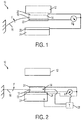
- FIG. 1 a first embodiment 10 of a heat transfer system according to the present disclosure is illustrated.
- An object to be cooled 12 is at an initial temperature T1.
- An electrocaloric structure 14, carried by a suspension 16 is disposed to be in physical contact with object 12. This contact can, for example, be a result of bias applied by the suspension, which may be a spring or the like (with variations discussed further herein).
- electrocaloric structure 14 comprises an electrocaloric body 18 (for example polymers and co-polymers such as poly[(vinylidenefluoride-co-trifluoroethylene] [P(VDF-TrFE)], ceramic materials such as lead zirconium titanate PZT, etc.) having ohmic layers 20, 22 on top and bottom surfaces.
- Ohmic layers 20, 22 are electrically connected, for example, to a switchable voltage source V.
- Switchable voltage source V provides a signal, in the form of a voltage, to selectively produce an electric field within the electrocaloric material 18.
- electrocaloric structure 14 In the absence of an electric field, or alternatively where the field assumes a first state (indicated by V ⁇ ), electrocaloric structure 14 is at a temperature T2 such that T2 ⁇ T1. Electrocaloric structure 14 will change temperature by an amount ⁇ T1, such that electrocaloric structure 14 attains a new temperature T2+ ⁇ T1.
- a heat sink structure 24 is disposed proximate but physically spaced apart from electrocaloric structure 14 in the V ⁇ state.
- Heat sink structure 24 may include a passivated ohmic layer 26, or similar structure, electrically connected to a voltage source, and indeed in certain embodiments connected to voltage source V. This connection is such that when a voltage is applied across ohmic layer 22 and ohmic layer 26 an electric field is created, or alternatively the field assumes a second state (indicated by V ⁇ ), attracting ohmic layer 22 and ohmic layer 26 to one another. This results in electrocaloric structure 14 moving out of physical contact with object 12 and into physical contact with sink 24 (via passivated ohmic layer 26).
- the electric field (V ⁇ ) is also applied to electrocaloric material 18 by way of the voltage across ohmic layers 20, 22. This increases the temperature of electrocaloric material 18, by way of the electrocaloric effect, to a new temperature T3, such that T3>T2+ ⁇ T1.
- Heat sink 24 is initially at a temperature T4 such that T3>T4. Some amount of the heat energy, ⁇ Q2, may then be transferred from electrocaloric structure 14 to heat sink 24. Heat energy is thereby shuttled from object 12 to sink 24.
- the voltage source may then be switched to below a set threshold to decrease or remove the electric fields, resulting in a cooling of electrocaloric material 18 to a temperature T2, and a return of electrocaloric structure 14 by way of spring force F to physical contact with object 12. The above process may then be repeated.
- a single voltage source V is used to generate the fields for both motion of electrocaloric structure 14 and temperature change within the electrocaloric material 18, self-synchronizing electric field generation for these purposes is obtained.
- the aforementioned description applies to at least substantially steady-state operation of the system.
- operation of such a system When operation of such a system is initiated there will be a startup time during which the object to be cooled will gradually decrease in temperature until a steady-state temperature is reached (or nears steady-state such that some temperature cycling occurs with each phase of motion of electrocaloric structure 14).
- the temperature of the heat sink, or the heat output of the object to be cooled, or similar parameter changes the system will not operate at steady state.
- the steady state description provides an example of the system in operation, and one of ordinary skill in the art will understand that such a system will operate differently under different operating conditions.
- the timing and waveform of the decrease in voltage between ohmic layers 18, 22 and between ohmic layers 22, 26 may be controlled to optimize the thermal energy transfer between electrocaloric material 14 and the heat sink 24.
- the voltage may be decreased when it is sensed, for example by a sensor 28, that the temperature of electrocaloric material 18 and heat sink 24 are within a set threshold of one another.
- a voltage decreasing pattern or waveform may be employed, for example to decrease the voltage as the temperatures of electrocaloric material 18 and heat sink 24 approach one another, and further to initiate the movement of electrocaloric structure 14 by spring 16 (due to force F), such that as the two temperatures reach the set difference threshold electrocaloric structure 14 pulls away from heat sink 24.
- force F due to force F
- the temperature of other elements of the system (and ambient) may be used for timing control, voltage levels and waveform, etc., and those disclosed here are not intended to be limiting.
- electrostatic actuation of electrocaloric structure 14 ideally requires that the system be designed such that the high electric fields do not lead to arcing across the gap between ohmic layers 22 and 26.
- One means of achieving this is for the process be conducted in at least a near-vacuum (e.g., 10-3 to 10-4 Torr), and that travel of electrocaloric structure 16 (i.e., the spacing between the object 12 and sink 24) be relatively small (e.g., on the order of several micrometers or less).
- a near-vacuum e.g. 10-3 to 10-4 Torr
- travel of electrocaloric structure 16 i.e., the spacing between the object 12 and sink 24
- other embodiments for actuation of electrocaloric structure 16 may be employed.
- a magnetic actuation arrangement is contemplated.
- one or more of the aforementioned ohmic layers are replaced with electromagnetic coil structure, either formed in situ or applied to one or more of the surfaces of electrocaloric structure 14 and/or heat sink 24.
- Corresponding magnetic (ferrous) layers may be formed on electrocaloric structure 14 and/or heat sink 24 such that application of a voltage creates a magnetic field to attract electrocaloric structure 14 out of physical contact with object 12 and into physical contact with heat sink 24.
- the voltage used to create the motive magnetic field may also be used to create the electric field within the electrocaloric material, or alternatively synchronized with the voltage used to create the electric field, as described above, again resulting in self-synchronizing field generation.
- the ohmic layers may be formed as discrete electrode structures, full surface layers, etc.
- the number of layers and materials forming the contacts may be varied.
- Thermal communication between the electrocaloric structure and the object to be cooled and/or the heat sink may be via an electrode or the structure may be configured for direct physical contact between the electrocaloric material forming the electrocaloric layer and the object to be cooled and/or the reservoir.
- one or more surface layers such as thermal interface material, thermal grease, liquid film, liquid droplets, carbon nanotube "turf", etc., may also disposed on one or more of the electrocaloric structure, the object to be cooled, and/or the heat sink to improve thermal contact.
- the method of suspension of the stack may be varied, such as by coil spring, dual cantilever spring, magnetic biasing, etc. These variations are each capable of providing the function of a switched thermal pathway between an object to be cooled and a heat sink employing the electrocaloric effect of the materials comprising the system.
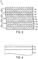
- an electrocaloric structure of the type described above may be a multi-layered structure such as illustrated in Fig. 3 .
- Structure 30 is comprised of alternating layers of ohmic material 32 (e.g., metal) and electrocaloric material (e.g., P(VDF-TrFE), PZT, etc.) 34.
- layer 32 may be on the order of 20 nm to 10 ⁇ m, and layer 35 on the order of 100 nm to 50 ⁇ m.
- Successive metal layers such as 32a and 32b, 32b and 32c, etc. may be electrically connected to voltage source V such that a field is generated within intervening electrocaloric layers 34a, 34b, etc. respectively.
- voltage source V such that a field is generated within intervening electrocaloric layers 34a, 34b, etc. respectively.
- ohmic layer 26 over heat sink 24 must be passivated to prevent shorting between ohmic layer 22 and ohmic layer 26. As shown in Fig. 4 , this can be accomplished, for example, by application of a dielectric layer 36 over ohmic layer 26. Alternatively, ohmic layer 22 may have applied thereover a passivation layer, or both ohmic layer 22 and ohmic layer 26 may be passivated.
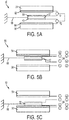
- Figs. 5A through 5C illustrate another embodiment 50 of the present disclosure, in three separate states of activation respectively.
- embodiment 50 comprises an electrocaloric structure 52 disposed an object to be cooled 54 and a heat sink 56.
- Electrocaloric structure 52 is suspended by one or more springs 66 or similar suspension mechanism, such that absent any field bias, electrocaloric structure 52 is suspended substantially between but not necessarily in contact with object to be cooled 54 and a heat sink 56.
- electrocaloric structure 52 may be in partial or full contact with either of object to be cooled 54 and a heat sink 56 in the absence of any electric field.
- electrocaloric structure 52 is provided with first and second ohmic layers 58, 60, object 54 is provided with an ohmic layer 62,and heat sink 56 is provide with ohmic layer 64.
- Each ohmic layer is connected to a voltage supply such that a desired voltage polarity may be applied thereto.
- coils and corresponding magnetic layers or other structures for electromagnetic actuation may alternatively be employed.
- electrocaloric structure 52 will be disposed between and spaced apart from both object 54 and heat sink 56. This is illustrated in Fig. 5A .
- electrostatic attraction will cause electrocaloric structure 52 to be brought into physical contact with object 54. This is illustrated in Fig. 5B . Due to the polarities applied to layers 58 and 60 being the same, no field is generated within the electrocaloric structure. Electrocaloric structure 52 may then receive heat energy from object 54.
- electrostatic attraction will cause electrocaloric structure 52 to leave physical contact with object 54 and be brought into physical contact with heat sink 56.
- Fig. 5C The voltages applied to layers 58 and 60 are of opposite polarity, thus causing an increase in the temperature of electrocaloric structure 52 due to the electrocaloric effect.
- Heat sink 56 may then receive heat energy from electrocaloric structure 52.
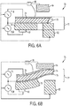
- Embodiment 70 comprises a layer structure 72 formed of a first layer 74 comprising an electrocaloric material and a second layer 76 comprising an electroactive polymer.
- An electroactive polymer experiences asymmetric strain, and hence flexes, when subject to an electric field.
- a first electrode 78 is disposed on electrocaloric material layer 74, and a second electrode 80 is disposed on electroactive polymer layer 76.
- a common electrode 79 may be disposed between electrodes 78 and 80, with intervening dielectric layers as needed.
- Electrodes 78, 80 are each electrically connected to voltage sources VI, V2, respectively, capable of applying voltages across electrodes 78-79 and 79-80 sufficient to generate fields of desired strength in each of layers 74, 76. These fields are capable of producing a temperature change in the electrocaloric material by way of the electrocaloric effect and deflection of the electroactive polymer.
- the layered structure 72 is disposed between an object to be cooled 82 and a heat sink 84. Initially, layered structure 72 is disposed to be in contact with object 82 (or alternatively in contact with a low thermal resistivity path to such an object), when no voltage is applied across electrodes 78-79, 79-80 (or at least an insufficient electric field is generated to cause deflection of electroactive polymer layer 76). This is illustrated in Fig. 6A . In this position, layered structure 72 receives some heat energy from object 82, effectively cooling object 82.
- the electrocaloric material layer 74 and the electroactive layer 76 may be configured such that electrocaloric material layer 74 may make direct physical (or thermal) contact with object 82 (and sink 84, depending on the state of the structure), such as by cantilevering the electrocaloric material layer 74 over the electroactive material layer 76, or other such arrangement.
- each of layers 74 and 76 separate fields are generated in each of layers 74 and 76 by voltage sources VI, V2 , respectively. It will be appreciated that the generation of these voltages are cooperatively controlled such that the temperature change and motion of layered structure 72 are self-synchronizing.
- the materials and dimensions of layers 74, 76 maybe selected such that a single voltage source (not shown) may produce a single electric field across electrodes 78, 80, resulting in a temperature change in the electrocaloric material 74 and a physical deformation of the electroactive polymer 76.
- a voltage (provided by voltage source V2) may then be applied between electrodes 79, 80 creating a sufficiently high electric field to cause the electroactive polymer layer 76 to deflect, such that layer structure 72 is caused to be removed from contact with object 82 and brought into contact with a heat sink 84 (or a low thermal resistivity path to a heat sink). This is illustrated in Fig. 6B .
- a second voltage from voltage source VI between electrodes 78, 79 also causes a rise in temperature of the electrocaloric material 74. If the net temperature of layer structure 72 exceeds the temperature of heat sink 84, thermal energy will be transferred from layer structure 72 to heat sink 84.
- the voltages between electrodes 78, 79 and between 79, 80 are then decreased or removed, permitting layer structure 72 to drop in temperature and return to contact with object 82, and the process repeated.
- the electrocaloric material 74 and electroactive polymer 76 are actuated in a selfsynchronizing manner. By oscillating the voltages, this structure can be used to repeatedly extract heat from (cool) object 82 and reject that heat to the heat sink 84.
- the timing and waveform of the decrease in voltage between electrodes 78, 80 may be controlled to optimize the thermal energy transfer between the layer structure 72 and the heat sink 84.
- the voltage may be decreased when it is sensed, for example by sensor 86, that the temperature of the layer structure and heat sink 84 are within a set threshold of one another.
- a voltage decreasing pattern or waveform may be employed to, for example decrease the voltage as the temperatures of the layer structure and heat sink 84 approach one another, such that as the two temperatures reach the set difference threshold the layer structure 72 pulls away from heat sink 84.
- an array of electrocaloric structures and intermediate structures may be disposed between thermal energy source and sink.
- an embodiment 90 is shown comprising an object to be cooled 92, a heat sink 94, and a plurality of electrocaloric structures 96a, 96b, etc.
- various of electrocaloric structures 96a, 96b, etc. may have affixed ohmic layers (not shown), which in turn may be passivated to prevent shorting in electrostatically-actuated embodiments.
- Fig. 7A illustrates one configuration of the device in which the first electrocaloric structure 96a is in thermal contact with the object to be cooled 92, and is physically separated from the second electrocaloric structure 96b.
- Structure 96c is, in turn, in thermal contact with structure 96b, but is physically separated from structure 96d.
- the last electrocaloric structure 96e is physically separated from the heat sink 94 (although this description is not limited to a pattern of 5 electrocaloric structures, and may repeat an arbitrary number of times).
- the first configuration shown in Fig. 7A may be effected by a physical bias, such as a spring, or an electrostatic force created by a first voltage applied between object to be cooled 92 and first electrocaloric structure 96a, a second voltage applied between second electrocaloric structure 96b and third electrocaloric structure 96c, etc., or by another mechanism as described previously.
- a physical bias such as a spring
- electrostatic force created by a first voltage applied between object to be cooled 92 and first electrocaloric structure 96a, a second voltage applied between second electrocaloric structure 96b and third electrocaloric structure 96c, etc., or by another mechanism as described previously.
- the relatively high voltages across structures 96b and 96d may be the same voltages that generate electrostatic attraction between the various thermally connected elements. In this way the device is "self-synchronized" as previously described.
- the configuration of the system is changed to a second configuration shown in Fig. 7B .
- this is effected by applying voltages between structure 96a and structure 96b, between structure 96c and structure 96d, and between structure 96e and the heat sink 94.
- the electrostatic voltages between object 92 and structure 96a, between structure 96b and structure 96c, between structure 96d and structure 96e are reduced.
- magnetic forces, electroactive polymers, or other means as previously described effect the transition between configurations.
- the relatively high voltages across structures 96a, 96c, and 96e may be the same voltages that generate electrostatic attraction between the various thermally connected elements, that actuate the electroactive polymers, or that energize magnetic or other means of actuation.
- FIGs. 7A and 7B show five electrocaloric structures 96a, 96b, 96c, 96d, and 96e, this is merely one embodiment used for illustrating the general principles of the present disclosure, and systems with fewer or more electrocaloric structures may be used.
- an electrocaloric structure may be suspended from one side by a cantilever type spring. This arrangement is shown for clarity, and is only one of many possible suspension embodiments.
- the method of suspension may be varied, such as by coil spring, multiple cantilever spring, magnetic biasing, etc.
- an electrocaloric structure 102 may equivalently be suspended between a thermal energy source 104 and sink 106 from multiple sides, by first spring 108a and second spring 108b (or additional or alternate springs, not shown, extending into the plane of Fig. 8 ).
- first spring 108a and second spring 108b or additional or alternate springs, not shown, extending into the plane of Fig. 8 .
- an electrocaloric structure 112 may be suspended between a thermal energy source 114 and sink 116 by way of a spring 118 disposed below electrocaloric structure 112.
- the conductivity and passivation of springs and surfaces are determined so as to permit any of the above motive methodologies described above, such as electrostatic, magnetic, electroactive, etc.
- a still further embodiment 120 is shown in Fig. 10 , according to which an electrocaloric structure 122 is suspended between a thermal energy source 124 and sink 126 from top and bottom, by first spring 128a and second spring 128b. Combinations of these suspension arrangements, and others not explicitly illustrated are also contemplated herein. These various embodiments illustrate that many different suspension arrangements are contemplated, and are not as such limiting to the scope of the claims of this disclosure.
- a heat source may be provided in place of an object to be cooled.
- the electrocaloric device may shuttle heat from the heat source to an object to be heated by again controlling motion of the electrocaloric device between the heat source and object to be heated synchronously with the application of an electric field controlling the temperature of the electrocaloric device.
- the electrocaloric device When the electrocaloric device is in thermal contact with the heat source, the field may be absent, and the electrocaloric device is initially cooler than the heat source.
- the electrocaloric device may receive heat from the heat source, then be moved, by a method and structure such as those described above, into thermal contact with the object to be heated.
- An electric field may be applied to the electrocaloric device elevating its temperature above that of the object to be heated, resulting in heat transfer from the electrocaloric device to the object to be heated.
- the field(s) controlling the electrocaloric device temperature and motion may be the same, originate from the same voltage, or otherwise by synchronized, such as by a common control of separate voltage supplies, such the system is "self-synchronizing".
- the electrocaloric device may be returned to thermal contact with the heat source, and the process repeated, again as described above.
- first layer when a first layer is referred to as being “on” or “over” a second layer or substrate, it can be directly on the second layer or substrate, or on an intervening layer or layers may be between the first layer and second layer or substrate. Further, when a first layer is referred to as being “on” or “over” a second layer or substrate, the first layer may cover the entire second layer or substrate or a portion of the second layer or substrate. For example, heat transfer between the electrocaloric material and the heat source/sink can be facilitated by adding a thermal interface material, thermal grease, liquid metal droplet array, or another similar treatment above or below selected layers or structures described above.
Landscapes
- Engineering & Computer Science (AREA)
- Physics & Mathematics (AREA)
- Mechanical Engineering (AREA)
- Thermal Sciences (AREA)
- General Engineering & Computer Science (AREA)
- Micromachines (AREA)
- Cooling Or The Like Of Electrical Apparatus (AREA)
- Control Of Temperature (AREA)
Claims (9)
- System für gesteuerte Übertragung von Wärmeenergie, das umfasst:eine Wärmeenergie-Quelle (12);eine Wärmeenergie-Senke (24), die von der Wärmeenergie-Quelle beabstandet ist;eine Aufhängung (16);eine elektrokalorische Struktur (14), wobei die elektrokalorische Struktur von der Aufhängung (16) getragen wird und für abwechselnde physische Bewegung zwischen thermischer Verbindung mit der Wärmeenergie-Quelle und thermischer Verbindung mit der Wärmeenergie-Senke ausgeführt ist; sowieeine Steuersignal-Quelle (V), die gleichzeitig sowohl ein Temperatur-Steuersignal zum Steuern der Temperatur der elektrokalorischen Struktur als auch ein Bewegungs-Steuersignal zum Steuern der abwechselnden physischen Bewegung der elektrokalorischen Struktur zwischen thermischer Verbindung mit der Wärmeenergie-Quelle und thermischer Verbindung mit der Wärmeenergie-Senke bereitstellt, wobeidie Aufhängung so ausgeführt ist, dass sie die elektrokalorische Struktur beim Nichtvorhandensein des Bewegungs-Steuersignals in thermische Verbindung mit der Wärmeenergie-Quelle vorspannt, und die Steuersignal-Quelle so ausgeführt ist, dass sie das Bewegungs-Steuersignal zum Bewegen der elektrokalorischen Struktur aus thermischer Verbindung mit der Wärmeenergie-Quelle gegen die Vorspannung in thermische Verbindung mit der Wärmeenergie-Senke bereitstellt.
- System nach Anspruch 1, wobei die Steuersignal-Quelle (V) so ausgeführt ist, dass das Temperatur-Steuersignal und das Bewegungs-Steuersignal das gleiche Signal sind.
- System nach Anspruch 1, wobei die elektrokalorische Struktur einen ersten ohmschen Kontakt (20) sowie einen zweiten ohmschen Kontakt (22) umfasst und des Weiteren die Steuersignal-Quelle (V) so mit dem ersten und dem zweiten ohmschen Kontakt gekoppelt ist, dass ein elektrisches Feld zwischen ihnen erzeugt wird, um eine steuerbare Temperaturänderung in der elektrokalorischen Struktur (14) zu bewirken.
- System nach Anspruch 1, wobei die elektrokalorische Struktur (14) einen elektrokalorischen Körper (18) mit einem ersten ohmschen Kontakt (20), einem zweiten ohmschen Kontakt (22) und einem Element eines Paares umfasst, das ein magnetisches Material oder einen Elektromagneten umfasst, und die Wärmeenergie-Senke (24) das andere von dem Paar aus magnetischem Material oder Elektromagnet umfasst, und wobei des Weiteren die Steuersignal-Quelle (V) so mit dem ersten und dem zweiten ohmschen Kontakt gekoppelt ist, dass ein elektrisches Feld zwischen ihnen erzeugt wird und eine steuerbare Temperaturänderung in der elektrokalorischen Struktur bewirkt, und wobei des Weiteren die Steuersignal-Quelle mit dem Elektromagneten gekoppelt ist, der ein Magnetfeld zwischen dem Elektromagneten und dem magnetischen Material erzeugt, das Bewegung der elektrokalorischen Struktur aus thermischer Verbindung mit der Wärmeenergie-Quelle (12) und in thermische Verbindung mit der Wärmeenergie-Senke bewirkt.
- System nach Anspruch 1, wobei die Aufhängung (16) eine elektroaktive Struktur (14) ist und des Weiteren die Steuersignal-Quelle (V) eine Spannung bereitstellt, die eine Verformung der elektroaktiven Struktur erzeugt, die Bewegung der elektrokalorischen Struktur aus thermischer Verbindung mit der Wärmeenergie-Quelle (12) in thermische Verbindung mit der Wärmeenergie-Senke (24) bewirkt.
- System nach Anspruch 1, das des Weiteren einen Temperatursensor (28) umfasst, der kommunizierend mit der elektrokalorischen Struktur (14) und der Steuersignal-Quelle (V) gekoppelt ist, und wobei des Weiteren die Steuersignal-Quelle so ausgeführt ist, dass sie auf ein durch den Temperatursensor bereitgestelltes Temperatursignal anspricht, um das Bewegungs-Steuersignal von einem Pegel über einem Schwellenwert, bei dem die elektrokalorische Struktur in thermischer Verbindung mit der Wärmeenergie-Senke (24) ist, auf einem Pegel unter einem Schwellenwert zu regulieren, bei dem die elektrokalorische Struktur nicht in thermischer Verbindung mit der Wärmeenergie-Senke ist.
- System nach Anspruch 1, wobei die Aufhängung (16) aus der Gruppe ausgewählt wird, die besteht aus:einer Feder (16), die an einer Seitenkante der elektrokalorischen Struktur (14) befestigt ist,einer Vielzahl von Federn (108a, 108b), die jeweils an einer anderen Seitenkante der elektrokalorischen Struktur befestigt sind,einer Feder, die an einer primären planen Fläche der elektrokalorischen Struktur befestigt ist, undeiner Vielzahl von Federn, die jeweils an einer anderen primären planen Fläche der elektrokalorischen Struktur befestigt sind.
- System nach Anspruch 1, wobei eine Vielzahl von elektrokalorischen Strukturen vorhanden sind, jede elektrokalorische Struktur von einer Aufhängung getragen wird und für abwechselnde physische Bewegung ausgeführt ist, die Steuersignal-Quelle (V) gleichzeitig sowohl ein Temperatur-Steuersignal zum Steuern der Temperatur jeder elektrokalorischen Struktur als auch ein Bewegungs-Steuersignal zum Steuern der abwechselnden physischen Bewegung jeder elektrokalorischen Struktur bereitstellt, und jede elektrokalorische Struktur für abwechselnde physische Bewegung in der entgegengesetzten Richtung zu jeder benachbarten elektrokalorischen Struktur ausgeführt ist und die Vielzahl elektrokalorischer Strukturen dadurch Wärmeenergie durch abwechselnden thermischen Kontakt zwischen benachbarten elektrokalorischen Strukturen überträgt.
- Verfahren für gesteuerte Übertragung von Wärmeenergie, das umfasst:Bereitstellen einer Wärmeenergie-Quelle (12);Bereitstellen einer Wärmeenergie-Senke (24), die von der Wärmeenergie-Quelle beabstandet ist;Bereitstellen einer Aufhängung (16);Anordnen einer elektrokalorischen Struktur (14) zwischen der Wärmeenergie-Quelle und der Wärmeenergie-Senke, wobei die elektrokalorische Struktur von der Aufhängung (16) getragen wird und für abwechselnde physische Bewegung zwischen thermischer Verbindung mit der Wärmeenergie-Quelle und thermischer Verbindung mit der Wärmeenergie-Senke ausgeführt ist; sowiegleichzeitiges Bereitstellen sowohl eines Temperatur-Steuersignals zum Steuern der Temperatur der elektrokalorischen Struktur als auch eines Bewegungs-Steuersignals zum Steuern der abwechselnden physischen Bewegung der elektrokalorischen Struktur zwischen thermischer Verbindung mit der Wärmeenergie-Quelle und thermischer Verbindung mit der Wärmeenergie-Senke über eine Steuersignal-Quelle (V), wobeidie Aufhängung die elektrokalorische Struktur beim Nichtvorhandensein des Bewegungs-Steuersignals in thermische Verbindung mit der Wärmeenergie-Quelle vorspannt, und die Steuersignal-Quelle das Bewegungs-Steuersignal zum Bewegen der elektrokalorischen Struktur aus thermischer Verbindung mit der Wärmeenergie-Quelle gegen die Vorspannung in thermische Verbindung mit der Wärmeenergie-Senke bereitstellt.
Applications Claiming Priority (1)
| Application Number | Priority Date | Filing Date | Title |
|---|---|---|---|
| US14/033,240 US9109818B2 (en) | 2013-09-20 | 2013-09-20 | Electrocaloric cooler and heat pump |
Publications (2)
| Publication Number | Publication Date |
|---|---|
| EP2851634A1 EP2851634A1 (de) | 2015-03-25 |
| EP2851634B1 true EP2851634B1 (de) | 2021-01-20 |
Family
ID=51584955
Family Applications (1)
| Application Number | Title | Priority Date | Filing Date |
|---|---|---|---|
| EP14185005.7A Not-in-force EP2851634B1 (de) | 2013-09-20 | 2014-09-16 | Elektrokalorischer Kühler und Wärmepumpe |
Country Status (4)
| Country | Link |
|---|---|
| US (1) | US9109818B2 (de) |
| EP (1) | EP2851634B1 (de) |
| JP (1) | JP6336859B2 (de) |
| KR (2) | KR20150032775A (de) |
Families Citing this family (21)
| Publication number | Priority date | Publication date | Assignee | Title |
|---|---|---|---|---|
| US9429344B2 (en) * | 2014-06-17 | 2016-08-30 | Palo Alto Research Center Incorporated | Electrocaloric system with active regeneration |
| WO2016156074A1 (en) | 2015-03-30 | 2016-10-06 | Basf Se | Mechanical heat switch and method |
| WO2016194700A1 (ja) * | 2015-06-04 | 2016-12-08 | 株式会社村田製作所 | 冷却デバイス |
| EP3334987B1 (de) * | 2015-08-14 | 2021-01-06 | United Technologies Corporation | Elektrokalorisches wärmetransfersystem |
| WO2017111921A1 (en) * | 2015-12-21 | 2017-06-29 | United Technologies Corporation | Method of forming electrodes on electrocaloric film |
| US10890361B2 (en) | 2016-06-08 | 2021-01-12 | Carrier Corporation | Electrocaloric heat transfer system |
| US10267544B2 (en) | 2016-06-08 | 2019-04-23 | Carrier Corporation | Electrocaloric heat transfer system |
| US20180164001A1 (en) * | 2016-12-12 | 2018-06-14 | Palo Alto Research Center Incorporated | Electrocaloric system |
| US11598561B2 (en) | 2017-06-16 | 2023-03-07 | Carrier Corporation | Electrocaloric element, a heat transfer system comprising an electrocaloric element and a method of making them |
| WO2018231603A1 (en) | 2017-06-16 | 2018-12-20 | Carrier Corporation | Ferroic response through application of a conjugate field |
| US20200212284A1 (en) * | 2017-06-16 | 2020-07-02 | Carrier Corporation | Method of making electrocaloric articles |
| JP7189201B2 (ja) * | 2017-10-23 | 2022-12-13 | オッポ広東移動通信有限公司 | 放熱装置、端末及び放熱装置の制御方法 |
| US11466906B2 (en) | 2017-11-30 | 2022-10-11 | Carrier Corporation | Electrocaloric heat transfer system |
| WO2020086694A1 (en) * | 2018-10-23 | 2020-04-30 | Carrier Corporation | Electrocaloric heat transfer system |
| US12044448B2 (en) | 2018-11-19 | 2024-07-23 | Carrier Corporation | Electrocaloric heat transfer system and method of operating the same |
| KR102229905B1 (ko) * | 2019-01-29 | 2021-03-18 | 중앙대학교 산학협력단 | 전기열량 효과를 이용한 냉감제공 구동기 및 전기열량 효과를 이용한 냉감제공 방법 |
| US12158291B1 (en) * | 2019-11-12 | 2024-12-03 | Iowa State University Research Foundation, Inc. | Low-force compressive and tensile actuation for elastocaloric heat pumps |
| JP7503968B2 (ja) * | 2020-08-26 | 2024-06-21 | 東京エレクトロン株式会社 | 熱量効果素子、伝熱装置、半導体製造装置及び熱量効果素子の制御方法 |
| WO2022270210A1 (ja) * | 2021-06-22 | 2022-12-29 | パナソニックIpマネジメント株式会社 | 熱交換システム |
| US20240019179A1 (en) * | 2022-07-13 | 2024-01-18 | Auburn University | Multi-layered electrocaloric heat pump systems and methods |
| CN117781378A (zh) * | 2022-10-26 | 2024-03-29 | 邵明玉 | 一种基于介电材料的空调 |
Family Cites Families (19)
| Publication number | Priority date | Publication date | Assignee | Title |
|---|---|---|---|---|
| US4136525A (en) * | 1976-12-30 | 1979-01-30 | International Business Machines Corporation | Dielectic refrigerator using orientable defect dipoles |
| US4757688A (en) * | 1986-04-01 | 1988-07-19 | Hughes Aircraft Company | Solid-state electrocaloric cooling system and method |
| US5644184A (en) * | 1996-02-15 | 1997-07-01 | Thermodyne, Inc. | Piezo-pyroelectric energy converter and method |
| DE10225602A1 (de) | 2002-06-07 | 2004-01-08 | Heraeus Sensor-Nite Gmbh | Halbleiterbauelement mit integrierter Schaltung, Kühlkörper und Temperatursensor |
| KR100459045B1 (ko) * | 2002-08-20 | 2004-12-03 | 이춘희 | 히트펌프 시스템 냉난방기 |
| US20100175392A1 (en) * | 2009-01-15 | 2010-07-15 | Malloy Kevin J | Electrocaloric refrigerator and multilayer pyroelectric energy generator |
| US8350444B2 (en) * | 2009-05-14 | 2013-01-08 | The Neothermal Energy Company | Method and apparatus for conversion of heat to electrical energy using polarizable materials and an internally generated poling field |
| US8344585B2 (en) * | 2009-05-14 | 2013-01-01 | The Neothermal Energy Company | Method and apparatus for conversion of heat to electrical energy using a new thermodynamic cycle |
| US8869542B2 (en) * | 2009-07-27 | 2014-10-28 | The Penn State Research Foundation | Polymer-based electrocaloric cooling devices |
| WO2011034594A1 (en) * | 2009-09-17 | 2011-03-24 | Materials And Electrochemical Research (Mer) Corporation | Flow-synchronous field motion refrigeration |
| US8371128B2 (en) * | 2009-11-17 | 2013-02-12 | Empire Technology Development, Llc | Thermal management with electrocaloric effect layer |
| US8695353B2 (en) * | 2009-12-17 | 2014-04-15 | Empire Technology Development Llc | Electrocaloric cooling |
| WO2012144995A1 (en) * | 2011-04-20 | 2012-10-26 | Empire Technology Development Llc | Heterogeneous electrocaloric effect heat transfer device |
| JP5278486B2 (ja) * | 2011-04-25 | 2013-09-04 | 株式会社デンソー | 熱磁気エンジン装置、および可逆熱磁気サイクル装置 |
| JP5418616B2 (ja) * | 2011-05-13 | 2014-02-19 | 株式会社デンソー | 熱磁気サイクル装置 |
| CN103814259B (zh) * | 2011-09-21 | 2015-12-16 | 英派尔科技开发有限公司 | 电热效应热传递装置尺寸应力控制 |
| US9010409B2 (en) | 2011-11-18 | 2015-04-21 | Palo Alto Research Center Incorporated | Thermal switch using moving droplets |
| US9349558B2 (en) | 2011-12-06 | 2016-05-24 | Palo Alto Research Center Incorporated | Mechanically acuated heat switch |
| JP2013160460A (ja) * | 2012-02-06 | 2013-08-19 | Daikin Industries Ltd | 空気調和装置 |
-
2013
- 2013-09-20 US US14/033,240 patent/US9109818B2/en active Active
-
2014
- 2014-09-02 JP JP2014178144A patent/JP6336859B2/ja not_active Expired - Fee Related
- 2014-09-02 KR KR20140116131A patent/KR20150032775A/ko not_active Withdrawn
- 2014-09-03 KR KR1020140116829A patent/KR102126170B1/ko not_active Expired - Fee Related
- 2014-09-16 EP EP14185005.7A patent/EP2851634B1/de not_active Not-in-force
Non-Patent Citations (1)
| Title |
|---|
| None * |
Also Published As
| Publication number | Publication date |
|---|---|
| US20150082809A1 (en) | 2015-03-26 |
| JP2015059739A (ja) | 2015-03-30 |
| KR20150032776A (ko) | 2015-03-30 |
| KR20150032775A (ko) | 2015-03-30 |
| KR102126170B1 (ko) | 2020-06-25 |
| JP6336859B2 (ja) | 2018-06-06 |
| US9109818B2 (en) | 2015-08-18 |
| EP2851634A1 (de) | 2015-03-25 |
Similar Documents
| Publication | Publication Date | Title |
|---|---|---|
| EP2851634B1 (de) | Elektrokalorischer Kühler und Wärmepumpe | |
| US9429344B2 (en) | Electrocaloric system with active regeneration | |
| US10700621B2 (en) | Vortex flux generator | |
| US9777953B2 (en) | Apparatus for thermally cycling an object including a polarizable material | |
| US11933524B2 (en) | Tandem-structured cooling device driven by electrostatic force | |
| US12034385B2 (en) | Vortex flux generator | |
| WO2012025137A1 (en) | Micromechanical pyroelectric generator | |
| GB2514617A (en) | Energy converter | |
| Hehlen et al. | Electrocaloric refrigerator using electrohydrodynamic flows in dielectric fluids | |
| Novak et al. | Electrocaloric devices using cantilever structures | |
| Cheng et al. | A novel thermomagnetic rotational-actuator | |
| US20150300328A1 (en) | Thermoelectric generator comprising a deformable by-layer membrane exhibiting magnetic properties | |
| Chen | Energy Harvesting Based on Bistable Shape Memory Film Actuation | |
| Lee et al. | A Novel Procedure for Pyroelectric Energy Harvesting Using Heat Conduction and the Olsen Cycle | |
| WO2014110788A1 (en) | Contactor |
Legal Events
| Date | Code | Title | Description |
|---|---|---|---|
| PUAI | Public reference made under article 153(3) epc to a published international application that has entered the european phase |
Free format text: ORIGINAL CODE: 0009012 |
|
| 17P | Request for examination filed |
Effective date: 20140916 |
|
| AK | Designated contracting states |
Kind code of ref document: A1 Designated state(s): AL AT BE BG CH CY CZ DE DK EE ES FI FR GB GR HR HU IE IS IT LI LT LU LV MC MK MT NL NO PL PT RO RS SE SI SK SM TR |
|
| AX | Request for extension of the european patent |
Extension state: BA ME |
|
| R17P | Request for examination filed (corrected) |
Effective date: 20151007 |
|
| RBV | Designated contracting states (corrected) |
Designated state(s): AL AT BE BG CH CY CZ DE DK EE ES FI FR GB GR HR HU IE IS IT LI LT LU LV MC MK MT NL NO PL PT RO RS SE SI SK SM TR |
|
| GRAP | Despatch of communication of intention to grant a patent |
Free format text: ORIGINAL CODE: EPIDOSNIGR1 |
|
| STAA | Information on the status of an ep patent application or granted ep patent |
Free format text: STATUS: GRANT OF PATENT IS INTENDED |
|
| INTG | Intention to grant announced |
Effective date: 20200821 |
|
| GRAS | Grant fee paid |
Free format text: ORIGINAL CODE: EPIDOSNIGR3 |
|
| GRAA | (expected) grant |
Free format text: ORIGINAL CODE: 0009210 |
|
| STAA | Information on the status of an ep patent application or granted ep patent |
Free format text: STATUS: THE PATENT HAS BEEN GRANTED |
|
| AK | Designated contracting states |
Kind code of ref document: B1 Designated state(s): AL AT BE BG CH CY CZ DE DK EE ES FI FR GB GR HR HU IE IS IT LI LT LU LV MC MK MT NL NO PL PT RO RS SE SI SK SM TR |
|
| REG | Reference to a national code |
Ref country code: GB Ref legal event code: FG4D |
|
| REG | Reference to a national code |
Ref country code: CH Ref legal event code: EP |
|
| REG | Reference to a national code |
Ref country code: DE Ref legal event code: R096 Ref document number: 602014074344 Country of ref document: DE |
|
| REG | Reference to a national code |
Ref country code: AT Ref legal event code: REF Ref document number: 1356756 Country of ref document: AT Kind code of ref document: T Effective date: 20210215 |
|
| REG | Reference to a national code |
Ref country code: IE Ref legal event code: FG4D |
|
| REG | Reference to a national code |
Ref country code: NL Ref legal event code: MP Effective date: 20210120 |
|
| REG | Reference to a national code |
Ref country code: LT Ref legal event code: MG9D |
|
| REG | Reference to a national code |
Ref country code: AT Ref legal event code: MK05 Ref document number: 1356756 Country of ref document: AT Kind code of ref document: T Effective date: 20210120 |
|
| PG25 | Lapsed in a contracting state [announced via postgrant information from national office to epo] |
Ref country code: FI Free format text: LAPSE BECAUSE OF FAILURE TO SUBMIT A TRANSLATION OF THE DESCRIPTION OR TO PAY THE FEE WITHIN THE PRESCRIBED TIME-LIMIT Effective date: 20210120 Ref country code: HR Free format text: LAPSE BECAUSE OF FAILURE TO SUBMIT A TRANSLATION OF THE DESCRIPTION OR TO PAY THE FEE WITHIN THE PRESCRIBED TIME-LIMIT Effective date: 20210120 Ref country code: GR Free format text: LAPSE BECAUSE OF FAILURE TO SUBMIT A TRANSLATION OF THE DESCRIPTION OR TO PAY THE FEE WITHIN THE PRESCRIBED TIME-LIMIT Effective date: 20210421 Ref country code: PT Free format text: LAPSE BECAUSE OF FAILURE TO SUBMIT A TRANSLATION OF THE DESCRIPTION OR TO PAY THE FEE WITHIN THE PRESCRIBED TIME-LIMIT Effective date: 20210520 Ref country code: LT Free format text: LAPSE BECAUSE OF FAILURE TO SUBMIT A TRANSLATION OF THE DESCRIPTION OR TO PAY THE FEE WITHIN THE PRESCRIBED TIME-LIMIT Effective date: 20210120 Ref country code: BG Free format text: LAPSE BECAUSE OF FAILURE TO SUBMIT A TRANSLATION OF THE DESCRIPTION OR TO PAY THE FEE WITHIN THE PRESCRIBED TIME-LIMIT Effective date: 20210420 Ref country code: NO Free format text: LAPSE BECAUSE OF FAILURE TO SUBMIT A TRANSLATION OF THE DESCRIPTION OR TO PAY THE FEE WITHIN THE PRESCRIBED TIME-LIMIT Effective date: 20210420 Ref country code: NL Free format text: LAPSE BECAUSE OF FAILURE TO SUBMIT A TRANSLATION OF THE DESCRIPTION OR TO PAY THE FEE WITHIN THE PRESCRIBED TIME-LIMIT Effective date: 20210120 |
|
| PG25 | Lapsed in a contracting state [announced via postgrant information from national office to epo] |
Ref country code: SE Free format text: LAPSE BECAUSE OF FAILURE TO SUBMIT A TRANSLATION OF THE DESCRIPTION OR TO PAY THE FEE WITHIN THE PRESCRIBED TIME-LIMIT Effective date: 20210120 Ref country code: RS Free format text: LAPSE BECAUSE OF FAILURE TO SUBMIT A TRANSLATION OF THE DESCRIPTION OR TO PAY THE FEE WITHIN THE PRESCRIBED TIME-LIMIT Effective date: 20210120 Ref country code: LV Free format text: LAPSE BECAUSE OF FAILURE TO SUBMIT A TRANSLATION OF THE DESCRIPTION OR TO PAY THE FEE WITHIN THE PRESCRIBED TIME-LIMIT Effective date: 20210120 Ref country code: PL Free format text: LAPSE BECAUSE OF FAILURE TO SUBMIT A TRANSLATION OF THE DESCRIPTION OR TO PAY THE FEE WITHIN THE PRESCRIBED TIME-LIMIT Effective date: 20210120 Ref country code: AT Free format text: LAPSE BECAUSE OF FAILURE TO SUBMIT A TRANSLATION OF THE DESCRIPTION OR TO PAY THE FEE WITHIN THE PRESCRIBED TIME-LIMIT Effective date: 20210120 |
|
| PG25 | Lapsed in a contracting state [announced via postgrant information from national office to epo] |
Ref country code: IS Free format text: LAPSE BECAUSE OF FAILURE TO SUBMIT A TRANSLATION OF THE DESCRIPTION OR TO PAY THE FEE WITHIN THE PRESCRIBED TIME-LIMIT Effective date: 20210520 |
|
| REG | Reference to a national code |
Ref country code: DE Ref legal event code: R097 Ref document number: 602014074344 Country of ref document: DE |
|
| PG25 | Lapsed in a contracting state [announced via postgrant information from national office to epo] |
Ref country code: SM Free format text: LAPSE BECAUSE OF FAILURE TO SUBMIT A TRANSLATION OF THE DESCRIPTION OR TO PAY THE FEE WITHIN THE PRESCRIBED TIME-LIMIT Effective date: 20210120 Ref country code: EE Free format text: LAPSE BECAUSE OF FAILURE TO SUBMIT A TRANSLATION OF THE DESCRIPTION OR TO PAY THE FEE WITHIN THE PRESCRIBED TIME-LIMIT Effective date: 20210120 Ref country code: CZ Free format text: LAPSE BECAUSE OF FAILURE TO SUBMIT A TRANSLATION OF THE DESCRIPTION OR TO PAY THE FEE WITHIN THE PRESCRIBED TIME-LIMIT Effective date: 20210120 |
|
| PLBE | No opposition filed within time limit |
Free format text: ORIGINAL CODE: 0009261 |
|
| STAA | Information on the status of an ep patent application or granted ep patent |
Free format text: STATUS: NO OPPOSITION FILED WITHIN TIME LIMIT |
|
| PG25 | Lapsed in a contracting state [announced via postgrant information from national office to epo] |
Ref country code: ES Free format text: LAPSE BECAUSE OF FAILURE TO SUBMIT A TRANSLATION OF THE DESCRIPTION OR TO PAY THE FEE WITHIN THE PRESCRIBED TIME-LIMIT Effective date: 20210120 Ref country code: DK Free format text: LAPSE BECAUSE OF FAILURE TO SUBMIT A TRANSLATION OF THE DESCRIPTION OR TO PAY THE FEE WITHIN THE PRESCRIBED TIME-LIMIT Effective date: 20210120 Ref country code: RO Free format text: LAPSE BECAUSE OF FAILURE TO SUBMIT A TRANSLATION OF THE DESCRIPTION OR TO PAY THE FEE WITHIN THE PRESCRIBED TIME-LIMIT Effective date: 20210120 Ref country code: SK Free format text: LAPSE BECAUSE OF FAILURE TO SUBMIT A TRANSLATION OF THE DESCRIPTION OR TO PAY THE FEE WITHIN THE PRESCRIBED TIME-LIMIT Effective date: 20210120 |
|
| 26N | No opposition filed |
Effective date: 20211021 |
|
| PG25 | Lapsed in a contracting state [announced via postgrant information from national office to epo] |
Ref country code: AL Free format text: LAPSE BECAUSE OF FAILURE TO SUBMIT A TRANSLATION OF THE DESCRIPTION OR TO PAY THE FEE WITHIN THE PRESCRIBED TIME-LIMIT Effective date: 20210120 |
|
| PG25 | Lapsed in a contracting state [announced via postgrant information from national office to epo] |
Ref country code: SI Free format text: LAPSE BECAUSE OF FAILURE TO SUBMIT A TRANSLATION OF THE DESCRIPTION OR TO PAY THE FEE WITHIN THE PRESCRIBED TIME-LIMIT Effective date: 20210120 |
|
| REG | Reference to a national code |
Ref country code: DE Ref legal event code: R119 Ref document number: 602014074344 Country of ref document: DE |
|
| PG25 | Lapsed in a contracting state [announced via postgrant information from national office to epo] |
Ref country code: IT Free format text: LAPSE BECAUSE OF FAILURE TO SUBMIT A TRANSLATION OF THE DESCRIPTION OR TO PAY THE FEE WITHIN THE PRESCRIBED TIME-LIMIT Effective date: 20210120 |
|
| REG | Reference to a national code |
Ref country code: CH Ref legal event code: PL |
|
| REG | Reference to a national code |
Ref country code: BE Ref legal event code: MM Effective date: 20210930 |
|
| GBPC | Gb: european patent ceased through non-payment of renewal fee |
Effective date: 20210916 |
|
| PG25 | Lapsed in a contracting state [announced via postgrant information from national office to epo] |
Ref country code: IS Free format text: LAPSE BECAUSE OF FAILURE TO SUBMIT A TRANSLATION OF THE DESCRIPTION OR TO PAY THE FEE WITHIN THE PRESCRIBED TIME-LIMIT Effective date: 20210520 Ref country code: MC Free format text: LAPSE BECAUSE OF FAILURE TO SUBMIT A TRANSLATION OF THE DESCRIPTION OR TO PAY THE FEE WITHIN THE PRESCRIBED TIME-LIMIT Effective date: 20210120 |
|
| PG25 | Lapsed in a contracting state [announced via postgrant information from national office to epo] |
Ref country code: LU Free format text: LAPSE BECAUSE OF NON-PAYMENT OF DUE FEES Effective date: 20210916 Ref country code: IE Free format text: LAPSE BECAUSE OF NON-PAYMENT OF DUE FEES Effective date: 20210916 Ref country code: GB Free format text: LAPSE BECAUSE OF NON-PAYMENT OF DUE FEES Effective date: 20210916 Ref country code: FR Free format text: LAPSE BECAUSE OF NON-PAYMENT OF DUE FEES Effective date: 20210930 Ref country code: DE Free format text: LAPSE BECAUSE OF NON-PAYMENT OF DUE FEES Effective date: 20220401 Ref country code: BE Free format text: LAPSE BECAUSE OF NON-PAYMENT OF DUE FEES Effective date: 20210930 |
|
| PG25 | Lapsed in a contracting state [announced via postgrant information from national office to epo] |
Ref country code: LI Free format text: LAPSE BECAUSE OF NON-PAYMENT OF DUE FEES Effective date: 20210930 Ref country code: CH Free format text: LAPSE BECAUSE OF NON-PAYMENT OF DUE FEES Effective date: 20210930 |
|
| PG25 | Lapsed in a contracting state [announced via postgrant information from national office to epo] |
Ref country code: HU Free format text: LAPSE BECAUSE OF FAILURE TO SUBMIT A TRANSLATION OF THE DESCRIPTION OR TO PAY THE FEE WITHIN THE PRESCRIBED TIME-LIMIT; INVALID AB INITIO Effective date: 20140916 |
|
| PG25 | Lapsed in a contracting state [announced via postgrant information from national office to epo] |
Ref country code: CY Free format text: LAPSE BECAUSE OF FAILURE TO SUBMIT A TRANSLATION OF THE DESCRIPTION OR TO PAY THE FEE WITHIN THE PRESCRIBED TIME-LIMIT Effective date: 20210120 |
|
| PG25 | Lapsed in a contracting state [announced via postgrant information from national office to epo] |
Ref country code: MK Free format text: LAPSE BECAUSE OF FAILURE TO SUBMIT A TRANSLATION OF THE DESCRIPTION OR TO PAY THE FEE WITHIN THE PRESCRIBED TIME-LIMIT Effective date: 20210120 |
|
| PG25 | Lapsed in a contracting state [announced via postgrant information from national office to epo] |
Ref country code: MT Free format text: LAPSE BECAUSE OF FAILURE TO SUBMIT A TRANSLATION OF THE DESCRIPTION OR TO PAY THE FEE WITHIN THE PRESCRIBED TIME-LIMIT Effective date: 20210120 |
|
| PG25 | Lapsed in a contracting state [announced via postgrant information from national office to epo] |
Ref country code: TR Free format text: LAPSE BECAUSE OF FAILURE TO SUBMIT A TRANSLATION OF THE DESCRIPTION OR TO PAY THE FEE WITHIN THE PRESCRIBED TIME-LIMIT Effective date: 20210120 |