EP2851588A1 - Quick release valve compressor - Google Patents
Quick release valve compressor Download PDFInfo
- Publication number
- EP2851588A1 EP2851588A1 EP14003269.9A EP14003269A EP2851588A1 EP 2851588 A1 EP2851588 A1 EP 2851588A1 EP 14003269 A EP14003269 A EP 14003269A EP 2851588 A1 EP2851588 A1 EP 2851588A1
- Authority
- EP
- European Patent Office
- Prior art keywords
- spindle
- compressor
- glands
- extending
- portions
- Prior art date
- Legal status (The legal status is an assumption and is not a legal conclusion. Google has not performed a legal analysis and makes no representation as to the accuracy of the status listed.)
- Granted
Links
Images



Classifications
-
- F—MECHANICAL ENGINEERING; LIGHTING; HEATING; WEAPONS; BLASTING
- F16—ENGINEERING ELEMENTS AND UNITS; GENERAL MEASURES FOR PRODUCING AND MAINTAINING EFFECTIVE FUNCTIONING OF MACHINES OR INSTALLATIONS; THERMAL INSULATION IN GENERAL
- F16K—VALVES; TAPS; COCKS; ACTUATING-FLOATS; DEVICES FOR VENTING OR AERATING
- F16K31/00—Actuating devices; Operating means; Releasing devices
- F16K31/44—Mechanical actuating means
-
- A—HUMAN NECESSITIES
- A61—MEDICAL OR VETERINARY SCIENCE; HYGIENE
- A61F—FILTERS IMPLANTABLE INTO BLOOD VESSELS; PROSTHESES; DEVICES PROVIDING PATENCY TO, OR PREVENTING COLLAPSING OF, TUBULAR STRUCTURES OF THE BODY, e.g. STENTS; ORTHOPAEDIC, NURSING OR CONTRACEPTIVE DEVICES; FOMENTATION; TREATMENT OR PROTECTION OF EYES OR EARS; BANDAGES, DRESSINGS OR ABSORBENT PADS; FIRST-AID KITS
- A61F13/00—Bandages or dressings; Absorbent pads
- A61F13/15—Absorbent pads, e.g. sanitary towels, swabs or tampons for external or internal application to the body; Supporting or fastening means therefor; Tampon applicators
- A61F13/15577—Apparatus or processes for manufacturing
- A61F13/15699—Forming webs by bringing together several webs, e.g. by laminating or folding several webs, with or without additional treatment of the webs
-
- A—HUMAN NECESSITIES
- A61—MEDICAL OR VETERINARY SCIENCE; HYGIENE
- A61F—FILTERS IMPLANTABLE INTO BLOOD VESSELS; PROSTHESES; DEVICES PROVIDING PATENCY TO, OR PREVENTING COLLAPSING OF, TUBULAR STRUCTURES OF THE BODY, e.g. STENTS; ORTHOPAEDIC, NURSING OR CONTRACEPTIVE DEVICES; FOMENTATION; TREATMENT OR PROTECTION OF EYES OR EARS; BANDAGES, DRESSINGS OR ABSORBENT PADS; FIRST-AID KITS
- A61F13/00—Bandages or dressings; Absorbent pads
- A61F13/15—Absorbent pads, e.g. sanitary towels, swabs or tampons for external or internal application to the body; Supporting or fastening means therefor; Tampon applicators
- A61F13/15577—Apparatus or processes for manufacturing
- A61F13/15707—Mechanical treatment, e.g. notching, twisting, compressing, shaping
-
- A—HUMAN NECESSITIES
- A61—MEDICAL OR VETERINARY SCIENCE; HYGIENE
- A61F—FILTERS IMPLANTABLE INTO BLOOD VESSELS; PROSTHESES; DEVICES PROVIDING PATENCY TO, OR PREVENTING COLLAPSING OF, TUBULAR STRUCTURES OF THE BODY, e.g. STENTS; ORTHOPAEDIC, NURSING OR CONTRACEPTIVE DEVICES; FOMENTATION; TREATMENT OR PROTECTION OF EYES OR EARS; BANDAGES, DRESSINGS OR ABSORBENT PADS; FIRST-AID KITS
- A61F13/00—Bandages or dressings; Absorbent pads
- A61F13/15—Absorbent pads, e.g. sanitary towels, swabs or tampons for external or internal application to the body; Supporting or fastening means therefor; Tampon applicators
- A61F13/45—Absorbent pads, e.g. sanitary towels, swabs or tampons for external or internal application to the body; Supporting or fastening means therefor; Tampon applicators characterised by the shape
- A61F13/49—Absorbent pads, e.g. sanitary towels, swabs or tampons for external or internal application to the body; Supporting or fastening means therefor; Tampon applicators characterised by the shape specially adapted to be worn around the waist, e.g. diapers or nappies
- A61F13/49007—Form-fitting, self-adjusting disposable diapers
- A61F13/49009—Form-fitting, self-adjusting disposable diapers with elastic means
- A61F13/4902—Form-fitting, self-adjusting disposable diapers with elastic means characterised by the elastic material
-
- F—MECHANICAL ENGINEERING; LIGHTING; HEATING; WEAPONS; BLASTING
- F16—ENGINEERING ELEMENTS AND UNITS; GENERAL MEASURES FOR PRODUCING AND MAINTAINING EFFECTIVE FUNCTIONING OF MACHINES OR INSTALLATIONS; THERMAL INSULATION IN GENERAL
- F16K—VALVES; TAPS; COCKS; ACTUATING-FLOATS; DEVICES FOR VENTING OR AERATING
- F16K7/00—Diaphragm valves or cut-off apparatus, e.g. with a member deformed, but not moved bodily, to close the passage ; Pinch valves
- F16K7/12—Diaphragm valves or cut-off apparatus, e.g. with a member deformed, but not moved bodily, to close the passage ; Pinch valves with flat, dished, or bowl-shaped diaphragm
-
- F—MECHANICAL ENGINEERING; LIGHTING; HEATING; WEAPONS; BLASTING
- F16—ENGINEERING ELEMENTS AND UNITS; GENERAL MEASURES FOR PRODUCING AND MAINTAINING EFFECTIVE FUNCTIONING OF MACHINES OR INSTALLATIONS; THERMAL INSULATION IN GENERAL
- F16K—VALVES; TAPS; COCKS; ACTUATING-FLOATS; DEVICES FOR VENTING OR AERATING
- F16K7/00—Diaphragm valves or cut-off apparatus, e.g. with a member deformed, but not moved bodily, to close the passage ; Pinch valves
- F16K7/12—Diaphragm valves or cut-off apparatus, e.g. with a member deformed, but not moved bodily, to close the passage ; Pinch valves with flat, dished, or bowl-shaped diaphragm
- F16K7/14—Diaphragm valves or cut-off apparatus, e.g. with a member deformed, but not moved bodily, to close the passage ; Pinch valves with flat, dished, or bowl-shaped diaphragm arranged to be deformed against a flat seat
- F16K7/16—Diaphragm valves or cut-off apparatus, e.g. with a member deformed, but not moved bodily, to close the passage ; Pinch valves with flat, dished, or bowl-shaped diaphragm arranged to be deformed against a flat seat the diaphragm being mechanically actuated, e.g. by screw-spindle or cam
Definitions
- the present invention relates to a technique for replacing a compressor in a valve; and more particularly relates to a technique for replacing a compressor in a diaphragm valve, including one having a weir.
- compressor replacement typically requires actuator dismanteling.
- the compressor is held in place by the diaphragm. During regular maintainance of diaphragm replacement, the compressor can fall off the assembly.
- Known diaphragms by the assignee of the instant patent application use two thread sizes, distinquishing diaphragm material. These diaphragms and the attachment methods associated with the same are known in the industry, and may also be referred to as the "ITT Advantage attachment method.” Changing between these materials requires reconstruction of the actuator in order to replace the mating compressor and thread components. A known assembly technique by the assignee of the present application allows these components in the known diaphragm to be easily changed on the customer process line.
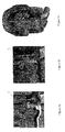
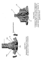
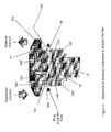
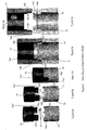
- Figures 1-3 show examples of prior art designs.
- Figure 1 shows typical uses of a shear pin (1) for compressor-to-spindle connections using fixed compressor connections that are known in the art.
- Figure 1a shows part of a valve having a PTFE diaphragm configuration requiring a threaded tube nut.
- Figure 1b shows part of a valve having an elastomer diaphragm configuration requiring a threaded compressor.
- Figure 1c shows part of a valve, in which the changing of the compressor and threaded tube-nut requires actuator disassembly for access to a shear pin connection.
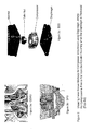
- Figure 2 shows a design for easy change out of a compressor, tube nut and diaphragm material type, using the aforementioned ADV 2.0 free compressor connection.
- Figure 3 shows three known methods for compressor attachment, where the compressor is free to fall from the actuator assembly when the diaphragm is removed.
- Figure 3a shows part of a known GEMU valve.
- Figure 3b shows part of a known SED valve.
- Figure 3c shows part of a known BBS valve.
- the present invention builds upon many advantages of the aforementioned known assembly technique by the assignee of the present application, while eliminating the drawback of having loose parts during typical maintainace diaphragm changes.
- a compressor may be held in place on the actuator assembly with a snap ring, e.g., using a commercial snap ring.
- the compressor can be pried off with a moderate force when the compressor and/or contained parts are changed out.
- this unique use of the snap ring may be applicable to many other products in many other industries.
- This compressor retension method according to the present invention may be used in most diaphragm valves.
- use of a snap ring to attach two parts with only the inner gland wall by way of sharing the peripheral space of engagement forms part of another unique concept implemented herein.
- This may also be applied to sharing the outer gland wall, as well as attaching a multitude of components with the inner gland wall, and/or the outer gland wall, etc.
- the compressor and threaded component that attaches to the diaphragm can be easily replaced, yet do not fall loose during normal diaphragm maintainance. Furthermore, security of the compressor and threaded component during operation is ensured by the diaphragm connection. This capability has been strongly requested by people in the industry, e.g. including customers of the assignee of the instant patent application.
- the present invention features apparatus, that may include, or take the form of, a quick release compressor combination, e.g., that may be used in a diaphragm valve, such as a weir-type diaphragm valve.
- the quick release compressor combination may include a spindle, a compressor and a snap ring.
- the spindle may include extending spindle portions configured with spindle glands.
- the compressor may include extending compressor portions configured with compressor glands.
- the snap ring may be configured to engage the spindle glands and the compressor glands in order to attach the spindle and the compressor together, so that the compressor may be quickly released from the spindle by releasing an engagement between the snap ring, the spindle glands and/or the compressor glands.
- the present invention may also include one or more of the following features:
- the spindle glands may be configured for facing outwardly away from the center of the spindle; the compressor glands may also be configured for facing outwardly away from the center of the compressor; and the snap ring may be configured to engage the spindle glands and the compressor glands so as to form a shared exterior gland.
- the spindle glands may be configured for facing inwardly towards the center of the spindle; the compressor glands may be configured for facing inwardly towards the center of the compressor; and the snap ring may be configured to engage the spindle glands and the compressor glands so as to form a shared interior gland.
- the scope of the invention is not intended to be limited to the direction in which the spindle or compressor glands are facing.
- the extending spindle portions may be configured on diametrically opposite sides of an end portion of the spindle; and the extending compressor portions may be configured on diametrically opposite sides of a center portion of the compressor.
- the extending spindle portions and the extending compressor portions may also be configured to mate and interlock when the snap ring engages the spindle glands and the compressor glands in order to attach the spindle and compressor together.
- the extending spindle portions, or the extending compressor portions, or both the extending spindle portions and the extending compressor portions, may be configured as partial cylindrical portions having partial cylindrical glands.
- the spindle has a longitudinal axis, and the extending spindle portions may be configured to extend substantially in parallel with the longitudinal axis of the spindle.
- the compressor has a central axis coaxial with the longitudinal axis of the spindle, and the extending compressor portions may be configured to extend substantially in parallel with the central axis of the compressor.
- the snap ring may be configured to engage the spindle glands and the compressor glands on a plane substantially perpendicular to the longitudinal axis of the spindle.
- the spindle glands and compressor glands may be configured as, or formed part of, a protruding rim, edge, rib, or collar on the extending spindle portions or the extending compressor portions.
- the extending spindle portions may include inwardly extending flanges configured to receive and engage outwardly extending flanges of, e.g., a tube nut that forms part of a diaphragm attachment; and the snap ring may be configured to engage the extending spindle portions in order to resist outward movement of the inwardly extending flanges and maintain a coupling, e.g., with the tube nut.
- the coupling between the inwardly extending flanges of the extending spindle portions and the outwardly extending flanges of the tube nut primarily holds the compressor in place during operation.
- the snap ring may include one side having a flat circumferential surface configured to engage the spindle glands; and the snap ring may also include an opposite side having a corresponding flat circumferential surface configured to engage the compressor glands.
- the snap ring may include an inner circumferential rim or surface configured to engage respective cylindrical wall portions, channels or grooves of the spindle glands and the compressor glands, so as to hold the snap ring in place.
- the snap ring, the spindle glands and the compressor glands may be configured to allow the compressor rotational freedom, e.g., on a single axis.
- the spindle may be made by a cast spindle design, or by either turning and milling, based at least partly on the fact that the spindle is configured without difficult interior cuts.
- the present invention may be implemented, e.g., in applicable products that may include diaphragm valves, including low cost actuator for bio pure diaphragm valves.
- the present invention may also have other applications, e.g., vis-a-vis compressor attachment to linear actuator valves.
- the present invention may take the form of apparatus generally indicated as 10 (see Figure 4a ), e.g., that includes, or takes the form of, a quick release compressor combination, e.g., that may be used in a diaphragm valve, such as a weir-type diaphragm valve.
- the apparatus 10 features at least in part a combination of a actuator spindle 12, a compressor 14 and a snap ring 16, consistent with that shown in Figures 4 to 6 .
- the spindle 12 may include extending spindle portions 12a', 12a" configured with spindle glands 12b', 12b".
- the compressor 14 may include extending compressor portions 14a', 14a" configured with compressor glands 14b', 14b".
- the snap ring 16 may be configured to engage the spindle glands 12b', 12b"and the compressor glands 14b', 14b" in order to attach the spindle 12 and the compressor 14 together, so that the compressor 14 may be quickly released from the spindle 12 by releasing an engagement between the snap ring 16, the spindle glands 12b', 12b" and the compressor glands 14b', 14b".
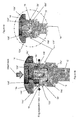
- Figures 4a and 4b shows the spindle 12, the compressor 14 and the snap ring 16 before their attachment.
- Figure 4a also shows a tube nut 18, e.g., that forms part of a diaphragm attachment.
- Figure 4b shows a beveled portion 12c configured on the extending spindle portions 12a', 12a" of the spindle 12, and how the snap ring 16 may expand to slip over the beveled portion 12c (also referred to herein as a spindle dart).
- Figures 4c , 4d(1) , 4d(2) , 4e(1) , 4e(2) and 4f all show the quick release compressor combination after the attachment between the spindle 12, the compressor 14 and the snap ring 16.
- the compressor 14 has gland walls, one of which is indicated by reference label 14c', that each may be configured with, or configured as, a respective compressor gland wall channel or groove, one of which is indicated by reference label 14d" to hold the slip ring 16 therein.
- Figures 4b and 4c show the spindle glands 12b', 12b", and how the spindle glands 12a', 12a" entrap the snap ring 16 (see Figure 4c).
- Figure 4c also shows how the tube nut 18 is captured within the spindle portions 12a', 12a" when the compressor 14 is attached to the spindle 12.
- Figures 4d(1) and 4d(2) show how the snap ring 16 engages the external spindle glands 12b', 12b" and the compressor glands 14b', 14b” on both components.
- Figure 4e(1) shows how the snap ring 16, the spindle glands the spindle glands 12b', 12b” and the compressor glands 14b', 14b” may be configured to allow the compressor 14 limited rotational freedom on a single axis, so as to allow the compressor 14 of the quick release compressor combination to move in the rotational directions as shown.
- Figure 4e(2) shows the attached quick release compressor combination shown in Figures 4c , 4d(1) , 4d(2) , 4e(1) , 4e(2) and 4f arranged in relation to a bonnet 20 that may form part of a diaphragm valve.
- Figure 4e(2) illustrates how engagement on the same side (e.g., the inside rim portion) of the snap ring 16 can allow for components having a smaller diameter, as required in some applications having special compressor spatial restrictions.
- Figure 4f shows how beveled portions, one of which is labeled 12c' (see also Figure 4b ), may be configured with, or take the form of, a low angle entry ramp that makes for an easy installation of the snap ring 16 in relation to the spindle glands 12b', 12b" and the compressor glands 14b', 14b".
- Figure 4f also shows high angle exit ramps, one of which is labeled 12e", configured on the extending spindle portions 12a', 12a" of the spindle 12 that can be manipulated or configured to provide for a desired removal force of the snap ring 16 from the attached combination of the spindle 12 and compressor 14.
- an attachment direction and a removal direction is indicated by the respectively labeled arrows.
- the spindle 12 in Figure 4 may be configured or manufactured using a cast design process.
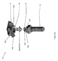
- Figure 5a shows a machine spindle 12' having a geometric design that is configured without difficult interior cuts so that the spindle 12 can be manufactured, e.g., by being turned and milled.
- the spindle 12' in Figure 5a can be manufactured or configured with a similar snap on and snap off performance as the spindle 12 in Figure 4 using the cast design.
- the quick release compressor combination may be configured with a shared exterior gland, and may include one or more of the following features particular to this embodiment:
- the spindle glands 12b', 12b" and the compressor glands 14b', 14b" may be configured as, or formed part of, a protruding rim, edge, rib, collar, groove or channel on the extending spindle portions 12a', 12a" or the extending compressor portions 14a', 14a", as shown.
- the extending spindle portions 12a', 12a" may include inwardly extending flanges 12d', 12d" configured to receive and engage outwardly extending flanges 18a', 18a" of the tube nut 18, e.g., that forms part of the diaphragm attachment; and the snap ring 16 may be configured to engage the extending spindle portions 12a', 12a" in order to resist outward movement of the inwardly extending flanges 12d', 12d” and maintain a coupling with the tube nut 18.
- the coupling between the inwardly extending flanges 12d', 12d" of the extending spindle portions 12a', 12a" and the outwardly extending flanges 18a', 18a" of the tube nut 18 primarily holds the compressor 14 in place during operation, e.g., of the diaphragm valve.
- the snap ring 16 may include one side having a flat circumferential surface configured to engage the spindle glands 12b', 12b"; and the snap ring 16 may also include an opposite side having a corresponding flat circumferential surface configured to engage the compressor glands 14b', 14b".
- the snap ring 16 may include an inner circumferential rim or surface configured to engage respective cylindrical wall portions or channels formed therein of the spindle glands 12b', 12b" and the compressor glands 14b', 14b".
- the quick release compressor combination in general may include one or more of the following features:
- Either the extending spindle portions 12a', 12a", or the extending compressor portions 14a', 14a", or both, may be configured as partial cylindrical portions having partial cylindrical glands, as shown.
- the spindle 12 has a longitudinal axis, and the extending spindle portions 12a', 12a" may be configured to extend substantially in parallel with the longitudinal axis of the spindle 12, as shown.
- the compressor 14 has a central axis coaxial with the longitudinal axis of the spindle 12, as shown, and the extending compressor portions 14a', 14a" may be configured to extend substantially in parallel with the central axis of the compressor 14, as also shown.
- the snap ring 16 may be configured to engage the spindle glands 12b', 12b" and the compressor glands 14b', 14b" on a plane substantially perpendicular to the longitudinal axis of the spindle 12, as shown.
- Figure 6 shows an alternative embodiment of the present invention in the form of a quick release compressor combination having a shared interior gland.
- the top element is indicated to be part of the spindle 12
- the bottom element is indicated to be part of the compressor 14; however, it is understood that the top element could be indicated to be part of the compressor 14, and the bottom element could be indicated to be part of the spindle 12 within the scope and spirit of the present invention.
- the spindle glands 12b', 12b" may be configured for facing inwardly towards the center of the spindle; the compressor glands 14b' (see Figure 6e ) may also be configured for facing inwardly towards the center of the compressor 14; and the snap ring 16 may be configured to engage the spindle glands 12b, 12b" and the compressor glands 14b' so as to form the shared interior gland, as best shown in Figure 6d .
- Figure 6a shows the combination of the spindle 12, the compressor 14 and the snap ring 16, before attachment.
- Figure 6b shows the snap ring 16 configured in the compressor 14.
- Figure 6c shows the spindle 12 and the compressor 14 attached together.
- Figure 6d shows the spindle 12 and the compressor 14 attached together by the snap ring 16.
- Figure 6e shows the spindle 12 removed from the compressor 14.
- the instant patent application sets forth two geometries or configurations for implementing the present invention.
- the scope of the invention is intended to include, and embodiments are envisioned, using other types or kinds of geometries either now known or later developed in the future within the spirit of the present invention, e.g., including other types or kinds of geometries for configuring the spindle, the compressor, or the snap ring for engaging and attaching the spindle and compressor together, so that the compressor may be quickly released from the spindle by releasing an engagement between the snap ring and portions of the spindle and the compressor.
Landscapes
- Engineering & Computer Science (AREA)
- Health & Medical Sciences (AREA)
- General Engineering & Computer Science (AREA)
- Mechanical Engineering (AREA)
- Vascular Medicine (AREA)
- Epidemiology (AREA)
- Biomedical Technology (AREA)
- Heart & Thoracic Surgery (AREA)
- Life Sciences & Earth Sciences (AREA)
- Animal Behavior & Ethology (AREA)
- General Health & Medical Sciences (AREA)
- Public Health (AREA)
- Veterinary Medicine (AREA)
- Manufacturing & Machinery (AREA)
- Compressor (AREA)
- Reciprocating Pumps (AREA)
Abstract
Description
- The present invention relates to a technique for replacing a compressor in a valve; and more particularly relates to a technique for replacing a compressor in a diaphragm valve, including one having a weir.
- In traditional designs, compressor replacement typically requires actuator dismanteling. In recent designs, the compressor is held in place by the diaphragm. During regular maintainance of diaphragm replacement, the compressor can fall off the assembly.
- Known diaphragms by the assignee of the instant patent application use two thread sizes, distinquishing diaphragm material. These diaphragms and the attachment methods associated with the same are known in the industry, and may also be referred to as the "ITT Advantage attachment method." Changing between these materials requires reconstruction of the actuator in order to replace the mating compressor and thread components. A known assembly technique by the assignee of the present application allows these components in the known diaphragm to be easily changed on the customer process line. These diaphragms and the attachment methods associated with the same are known in the industry, and may also be referred to as the "ITT Advantage, ADV, 2.0 attachment method." However, one dissadvantage of the known technique is that the interchangable components are loose during regular diaphragm replacement. Modern competitor systems have a similar situation and a similar problem.
-
Figures 1-3 show examples of prior art designs. - For example,
Figure 1 shows typical uses of a shear pin (1) for compressor-to-spindle connections using fixed compressor connections that are known in the art. -
Figure 1a shows part of a valve having a PTFE diaphragm configuration requiring a threaded tube nut.Figure 1b shows part of a valve having an elastomer diaphragm configuration requiring a threaded compressor.Figure 1c shows part of a valve, in which the changing of the compressor and threaded tube-nut requires actuator disassembly for access to a shear pin connection. - Moreover,
Figure 2 shows a design for easy change out of a compressor, tube nut and diaphragm material type, using the aforementioned ADV 2.0 free compressor connection. - Moreover still,
Figure 3 shows three known methods for compressor attachment, where the compressor is free to fall from the actuator assembly when the diaphragm is removed. For example,Figure 3a shows part of a known GEMU valve.Figure 3b shows part of a known SED valve.Figure 3c shows part of a known BBS valve. - There is a need in the industry for a better way to avoid having all these loose components during regular diaphragm replacement.
- In summary, the present invention builds upon many advantages of the aforementioned known assembly technique by the assignee of the present application, while eliminating the drawback of having loose parts during typical maintainace diaphragm changes. According to the present invention, during diaphragm changes a compressor may be held in place on the actuator assembly with a snap ring, e.g., using a commercial snap ring. The compressor can be pried off with a moderate force when the compressor and/or contained parts are changed out. In addition to use in valves, this unique use of the snap ring may be applicable to many other products in many other industries.
- This compressor retension method according to the present invention may be used in most diaphragm valves. In a broader stroke, use of a snap ring to attach two parts with only the inner gland wall by way of sharing the peripheral space of engagement forms part of another unique concept implemented herein. This may also be applied to sharing the outer gland wall, as well as attaching a multitude of components with the inner gland wall, and/or the outer gland wall, etc.
- When the present invention is implemented, the compressor and threaded component that attaches to the diaphragm can be easily replaced, yet do not fall loose during normal diaphragm maintainance. Furthermore, security of the compressor and threaded component during operation is ensured by the diaphragm connection. This capability has been strongly requested by people in the industry, e.g. including customers of the assignee of the instant patent application.
- According to some embodiments, the present invention features apparatus, that may include, or take the form of, a quick release compressor combination, e.g., that may be used in a diaphragm valve, such as a weir-type diaphragm valve. The quick release compressor combination may include a spindle, a compressor and a snap ring. The spindle may include extending spindle portions configured with spindle glands. The compressor may include extending compressor portions configured with compressor glands. The snap ring may be configured to engage the spindle glands and the compressor glands in order to attach the spindle and the compressor together, so that the compressor may be quickly released from the spindle by releasing an engagement between the snap ring, the spindle glands and/or the compressor glands.
- The present invention may also include one or more of the following features:
- The design is disclosed herein to have the spindle detach from the compressor/snap-ring sub-assembly, however, could be made to have the compressor detach from the spindle/snap-ring sub-assembly.
- The spindle glands may be configured for facing outwardly away from the center of the spindle; the compressor glands may also be configured for facing outwardly away from the center of the compressor; and the snap ring may be configured to engage the spindle glands and the compressor glands so as to form a shared exterior gland.
- Alternatively, the spindle glands may be configured for facing inwardly towards the center of the spindle; the compressor glands may be configured for facing inwardly towards the center of the compressor; and the snap ring may be configured to engage the spindle glands and the compressor glands so as to form a shared interior gland. In other words, the scope of the invention is not intended to be limited to the direction in which the spindle or compressor glands are facing.
- The extending spindle portions may be configured on diametrically opposite sides of an end portion of the spindle; and the extending compressor portions may be configured on diametrically opposite sides of a center portion of the compressor. The extending spindle portions and the extending compressor portions may also be configured to mate and interlock when the snap ring engages the spindle glands and the compressor glands in order to attach the spindle and compressor together.
- The extending spindle portions, or the extending compressor portions, or both the extending spindle portions and the extending compressor portions, may be configured as partial cylindrical portions having partial cylindrical glands.
- The spindle has a longitudinal axis, and the extending spindle portions may be configured to extend substantially in parallel with the longitudinal axis of the spindle. Moreover, the compressor has a central axis coaxial with the longitudinal axis of the spindle, and the extending compressor portions may be configured to extend substantially in parallel with the central axis of the compressor. The snap ring may be configured to engage the spindle glands and the compressor glands on a plane substantially perpendicular to the longitudinal axis of the spindle.
- The spindle glands and compressor glands may be configured as, or formed part of, a protruding rim, edge, rib, or collar on the extending spindle portions or the extending compressor portions.
- The extending spindle portions may include inwardly extending flanges configured to receive and engage outwardly extending flanges of, e.g., a tube nut that forms part of a diaphragm attachment; and the snap ring may be configured to engage the extending spindle portions in order to resist outward movement of the inwardly extending flanges and maintain a coupling, e.g., with the tube nut. The coupling between the inwardly extending flanges of the extending spindle portions and the outwardly extending flanges of the tube nut primarily holds the compressor in place during operation.
- The snap ring may include one side having a flat circumferential surface configured to engage the spindle glands; and the snap ring may also include an opposite side having a corresponding flat circumferential surface configured to engage the compressor glands.
- The snap ring may include an inner circumferential rim or surface configured to engage respective cylindrical wall portions, channels or grooves of the spindle glands and the compressor glands, so as to hold the snap ring in place.
- The snap ring, the spindle glands and the compressor glands may be configured to allow the compressor rotational freedom, e.g., on a single axis.
- The spindle may be made by a cast spindle design, or by either turning and milling, based at least partly on the fact that the spindle is configured without difficult interior cuts.
- The present invention may be implemented, e.g., in applicable products that may include diaphragm valves, including low cost actuator for bio pure diaphragm valves.
- The present invention may also have other applications, e.g., vis-a-vis compressor attachment to linear actuator valves.
- The drawing includes the following Figures, not necessarily drawn to scale:
-
Figure 1 includesFigures 1 a to 1 c and shows typical uses of a shear pin for compressor-to-spindle connections using a fixed compressor connection that are known in the art, whereFigure 1a shows a 3/4 cross-section view of part of a valve having a PTFE diaphragm configuration requiring a threaded tube nut; whereFigure 1b shows a 3/4 cross-section view of part of a valve having an elastomer diaphragm configuration requiring a threaded compressor; andFigure 1c shows a 3/4 cross-section view of part of a valve, in which the changing of the compressor and threaded tube-nut requires actuator disassembly for access to a shear pin connection. -
Figure 2 shows an exploded view of a design for easy change out of a compressor, tube nut and diaphragm material type, using the aforementioned known ADV 2.0 free compressor connection. -
Figure 3 includesFigures 3a to 3c and shows three known methods for compressor attachment, where the compressor is free to fall from the actuator assembly when the diaphragm is removed, whereFigure 3a shows a 3/4 cross-section view of part of a known GEMU valve, whereFigure 3b shows a partial side view of part of a known SED valve, and whereFigure 3c shows an exploded view of part of a known BBS valve. -
Figure 4 includesFigures 4a to 4f and shows the present invention in the form of a quick release compressor combination for use in diaphragm valves, according to some embodiments of the present invention, whereFigure 4a shows an exploded view of apparatus for forming an attachment between a spindle, a compressor and a snap ring, according to some embodiment of the present invention; whereFigure 4b shows a cross-sectional view of part of the apparatus shown inFigure 4a for forming the attachment between the spindle, the compressor and the snap ring, according to some embodiment of the present invention before attachment; whereFigure 4c shows a cross-sectional view of the apparatus shown inFigure 4b after the attachment between the spindle, the compressor and the snap ring, according to some embodiment of the present invention; whereFigure 4d(1) shows a 3/4 cross-sectional view of the apparatus shown inFigure 4c , according to some embodiment of the present invention; whereFigure 4d(2) shows an isometric view of the apparatus shown inFigure 4c , according to some embodiment of the present invention; whereFigure 4e(1) shows a side view of the apparatus shown inFigure 4d(2) , according to some embodiment of the present invention; whereFigure 4e(2) shows a 3/4 cross-sectional view of the apparatus shown inFigure 4e(1) arranged in a bonnet, according to some embodiment of the present invention; whereFigure 4f shows an enlarged view of the apparatus shown inFigure 4c , according to some embodiment of the present invention. -
Figure 5a shows an isometric view of a spindle that forms part of the apparatus, according to some embodiment of the present invention; andFigure 5b shows an exploded view of the apparatus for forming an attachment between a spindle, a compressor and a snap ring, according to some embodiment of the present invention; -
Figure 6 includesFigures 6a to 6e and shows the present invention in the form of a quick release compressor combination having a snap ring on a shared interior gland, whereFigure 6a shows an exploded view of apparatus having a spindle, a compressor and a snap ring, before attachment, according to some embodiment of the present invention; whereFigure 6b shows an exploded view of the apparatus shown inFigure 6a with the snap ring configured in the compressor, according to some embodiment of the present invention; whereFigure 6c shows a view of the apparatus shown inFigure 6b with the compressor and spindle attached together, according to some embodiment of the present invention; whereFigure 6d shows a cross-sectional view of the apparatus shown inFigure 6c with the compressor and spindle attached together by the snap ring, according to some embodiment of the present invention; and whereFigure 6e shows an exploded cross-sectional view of the apparatus shown inFigure 6d with the spindle removed from the compressor, according to some embodiment of the present invention. -
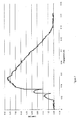
Figure 7 shows a graph of load (lbf) versus engagement (inches) of the force to install or attach the quick release compressor combination according to some embodiment of the present invention. - In the following description of the exemplary embodiment, reference is made to the accompanying Figures in the drawing, which form a part hereof, and in which are shown by way of illustration of an embodiment in which the invention may be practiced. It is to be understood that other embodiments may be utilized, as structural and operational changes may be made without departing from the scope of the present invention.
- Further, in an effort to reduce clutter in the drawing, each element or component set forth in the detailed description below is not necessarily indicated with its respective reference label and lead line in every Figure of the drawing.
- According to some embodiments, the present invention may take the form of apparatus generally indicated as 10 (see
Figure 4a ), e.g., that includes, or takes the form of, a quick release compressor combination, e.g., that may be used in a diaphragm valve, such as a weir-type diaphragm valve. Theapparatus 10 features at least in part a combination of aactuator spindle 12, acompressor 14 and asnap ring 16, consistent with that shown inFigures 4 to 6 . - By way of example, the
spindle 12 may include extendingspindle portions 12a', 12a" configured withspindle glands 12b', 12b". Thecompressor 14 may include extendingcompressor portions 14a', 14a" configured withcompressor glands 14b', 14b". In operation, thesnap ring 16 may be configured to engage thespindle glands 12b', 12b"and thecompressor glands 14b', 14b" in order to attach thespindle 12 and thecompressor 14 together, so that thecompressor 14 may be quickly released from thespindle 12 by releasing an engagement between thesnap ring 16, thespindle glands 12b', 12b" and thecompressor glands 14b', 14b". - In particular,
Figures 4a and4b shows thespindle 12, thecompressor 14 and thesnap ring 16 before their attachment.Figure 4a also shows atube nut 18, e.g., that forms part of a diaphragm attachment.Figure 4b shows abeveled portion 12c configured on the extendingspindle portions 12a', 12a" of thespindle 12, and how thesnap ring 16 may expand to slip over thebeveled portion 12c (also referred to herein as a spindle dart).Figures 4c ,4d(1) ,4d(2) ,4e(1) ,4e(2) and4f all show the quick release compressor combination after the attachment between thespindle 12, thecompressor 14 and thesnap ring 16. InFigures 4b and 4c , thecompressor 14 has gland walls, one of which is indicated by reference label 14c', that each may be configured with, or configured as, a respective compressor gland wall channel or groove, one of which is indicated byreference label 14d" to hold theslip ring 16 therein.Figures 4b and 4c show thespindle glands 12b', 12b", and how thespindle glands 12a', 12a" entrap the snap ring 16 (seeFigure 4c). Figure 4c also shows how thetube nut 18 is captured within thespindle portions 12a', 12a" when thecompressor 14 is attached to thespindle 12.Figures 4d(1) and 4d(2) show how thesnap ring 16 engages theexternal spindle glands 12b', 12b" and thecompressor glands 14b', 14b" on both components.Figure 4e(1) shows how thesnap ring 16, the spindle glands thespindle glands 12b', 12b" and thecompressor glands 14b', 14b" may be configured to allow thecompressor 14 limited rotational freedom on a single axis, so as to allow thecompressor 14 of the quick release compressor combination to move in the rotational directions as shown.Figure 4e(2) shows the attached quick release compressor combination shown inFigures 4c ,4d(1) ,4d(2) ,4e(1) ,4e(2) and4f arranged in relation to abonnet 20 that may form part of a diaphragm valve.Figure 4e(2) illustrates how engagement on the same side (e.g., the inside rim portion) of thesnap ring 16 can allow for components having a smaller diameter, as required in some applications having special compressor spatial restrictions.Figure 4f shows how beveled portions, one of which is labeled 12c' (see alsoFigure 4b ), may be configured with, or take the form of, a low angle entry ramp that makes for an easy installation of thesnap ring 16 in relation to thespindle glands 12b', 12b" and thecompressor glands 14b', 14b".Figure 4f also shows high angle exit ramps, one of which is labeled 12e", configured on the extendingspindle portions 12a', 12a" of thespindle 12 that can be manipulated or configured to provide for a desired removal force of thesnap ring 16 from the attached combination of thespindle 12 andcompressor 14. InFigure 4f , an attachment direction and a removal direction is indicated by the respectively labeled arrows. - By way of example, the
spindle 12 inFigure 4 may be configured or manufactured using a cast design process. - Alternatively,
Figure 5a shows a machine spindle 12' having a geometric design that is configured without difficult interior cuts so that thespindle 12 can be manufactured, e.g., by being turned and milled. The spindle 12' inFigure 5a can be manufactured or configured with a similar snap on and snap off performance as thespindle 12 inFigure 4 using the cast design. - By way of example, and consistent with that shown in
Figures 4-5 , the quick release compressor combination may be configured with a shared exterior gland, and may include one or more of the following features particular to this embodiment: - The
spindle glands 12b', 12b" may be configured to face outwardly away from the center of thespindle 12, as shown; thecompressor glands 14b', 14b" may also be configured to face outwardly away from the center of thecompressor 14, as shown; and thesnap ring 16 may be configured to engage thespindle glands 12b', 12b" and thecorresponding compressor glands 14b', 14b" so as to form the shared exterior gland. - The
spindle glands 12b', 12b" and thecompressor glands 14b', 14b" may be configured as, or formed part of, a protruding rim, edge, rib, collar, groove or channel on the extendingspindle portions 12a', 12a" or the extendingcompressor portions 14a', 14a", as shown. - The extending
spindle portions 12a', 12a" may include inwardly extendingflanges 12d', 12d" configured to receive and engage outwardly extendingflanges 18a', 18a" of thetube nut 18, e.g., that forms part of the diaphragm attachment; and thesnap ring 16 may be configured to engage the extendingspindle portions 12a', 12a" in order to resist outward movement of the inwardly extendingflanges 12d', 12d" and maintain a coupling with thetube nut 18. The coupling between the inwardly extendingflanges 12d', 12d" of the extendingspindle portions 12a', 12a" and the outwardly extendingflanges 18a', 18a" of thetube nut 18 primarily holds thecompressor 14 in place during operation, e.g., of the diaphragm valve. - The
snap ring 16 may include one side having a flat circumferential surface configured to engage thespindle glands 12b', 12b"; and thesnap ring 16 may also include an opposite side having a corresponding flat circumferential surface configured to engage thecompressor glands 14b', 14b". Thesnap ring 16 may include an inner circumferential rim or surface configured to engage respective cylindrical wall portions or channels formed therein of thespindle glands 12b', 12b" and thecompressor glands 14b', 14b". - By way of example, and consistent with that shown in
Figures 4-6 , the quick release compressor combination in general may include one or more of the following features: - The extending
spindle portions 12a', 12a" may be configured on diametrically opposite sides of an end portion of thespindle 12, as shown; and the extendingcompressor portions 14a', 14a" may be configured on diametrically opposite sides of a center portion of thecompressor 14, as also shown. The extendingspindle portions 12a', 12a" and the extendingcompressor portions 14a', 14a" may also be configured to mate and interlock when thesnap ring 16 engages thespindle glands 12b', 12b" and thecompressor glands 14b', 14b" in order to attach thespindle 12 andcompressor 14 together, as shown. - Either the extending
spindle portions 12a', 12a", or the extendingcompressor portions 14a', 14a", or both, may be configured as partial cylindrical portions having partial cylindrical glands, as shown. - The
spindle 12 has a longitudinal axis, and the extendingspindle portions 12a', 12a" may be configured to extend substantially in parallel with the longitudinal axis of thespindle 12, as shown. Moreover, thecompressor 14 has a central axis coaxial with the longitudinal axis of thespindle 12, as shown, and the extendingcompressor portions 14a', 14a" may be configured to extend substantially in parallel with the central axis of thecompressor 14, as also shown. Thesnap ring 16 may be configured to engage thespindle glands 12b', 12b" and thecompressor glands 14b', 14b" on a plane substantially perpendicular to the longitudinal axis of thespindle 12, as shown. -
Figure 6 shows an alternative embodiment of the present invention in the form of a quick release compressor combination having a shared interior gland. InFigure 6 , by way of example, the top element is indicated to be part of thespindle 12, and the bottom element is indicated to be part of thecompressor 14; however, it is understood that the top element could be indicated to be part of thecompressor 14, and the bottom element could be indicated to be part of thespindle 12 within the scope and spirit of the present invention. - In
Figure 6 , thespindle glands 12b', 12b" may be configured for facing inwardly towards the center of the spindle; thecompressor glands 14b' (seeFigure 6e ) may also be configured for facing inwardly towards the center of thecompressor 14; and thesnap ring 16 may be configured to engage thespindle glands compressor glands 14b' so as to form the shared interior gland, as best shown inFigure 6d . - In particular,
Figure 6a shows the combination of thespindle 12, thecompressor 14 and thesnap ring 16, before attachment.Figure 6b shows thesnap ring 16 configured in thecompressor 14.Figure 6c shows thespindle 12 and thecompressor 14 attached together.Figure 6d shows thespindle 12 and thecompressor 14 attached together by thesnap ring 16.Figure 6e shows thespindle 12 removed from thecompressor 14. - It should be understood that, unless stated otherwise herein, any of the features, characteristics, alternatives or modifications described regarding a particular embodiment herein may also be applied, used, or incorporated with any other embodiment described herein. Also, the drawings herein are not drawn to scale.
- Although the invention has been described and illustrated with respect to exemplary embodiments thereof, the foregoing and various other additions and omissions may be made therein and thereto without departing from the spirit and scope of the present invention.
- In particular, the scope of the invention is intended to include implementing the present invention in conjunction with the numerous embodiments set forth in the related applications set forth herein.
- By way of example, the instant patent application sets forth two geometries or configurations for implementing the present invention. However, the scope of the invention is intended to include, and embodiments are envisioned, using other types or kinds of geometries either now known or later developed in the future within the spirit of the present invention, e.g., including other types or kinds of geometries for configuring the spindle, the compressor, or the snap ring for engaging and attaching the spindle and compressor together, so that the compressor may be quickly released from the spindle by releasing an engagement between the snap ring and portions of the spindle and the compressor.
Claims (15)
- Apparatus (10) comprising:a spindle (12) having extending spindle portions (12a', 12a") configured with spindle glands (12b', 12b");a compressor (14) having extending compressor portions (14a', 14a") configured with compressor glands (14b', 14b"), anda snap ring (16) configured to engage the spindle glands (12b', 12b") and the compressor glands (14b', 14b") in order to attach the spindle (12) and the compressor (14) together, so that the compressor (14) may be quickly released from the spindle (12) by releasing an engagement between the snap ring (16), the spindle glands (12b', 12b") and/or the compressor glands (14b', 14b").
- Apparatus (10) according to claim 1, wherein
the spindle glands (12b', 12b") are configured for facing outwardly away from the center of the spindle (12);
the compressor glands (14b', 14b") are also configured for facing outwardly away from the center of the compressor (14); and
the snap ring (16) is configured to engage the spindle glands (12b', 12b") and the compressor glands (14b', 14b") so as to form a shared exterior gland. - Apparatus (10) according to claim 1, wherein
the spindle glands (12b', 12b") are configured for facing inwardly towards the center of the spindle (12);
the compressor glands (14b', 14b") are configured for facing inwardly towards the center of the spindle (12) or the compressor (14); and
the snap ring (16) is configured to engage the spindle glands (12b', 12b") and the compressor glands (14b', 14b") so as to form a shared interior gland. - Apparatus (10) according to claim 1, wherein
the extending spindle portions (12a', 12a") are configured on diametrically opposite sides of an end portion of the spindle (12); and
the extending compressor portions (14a', 14a") are configured on diametrically opposite sides of a center portion of the compressor (14). - Apparatus (10) according to claim 4, wherein
the extending spindle portions (12a', 12a") and the extending compressor portions (14a', 14a") are configured to mate and interlock when the snap ring (16) engages the spindle glands (12b', 12b") and the compressor glands (14b', 14b") in order to attach the spindle (12) and compressor (14) together. - Apparatus (10) according to claim 1, wherein the extending spindle portions (12a', 12a"), or the extending compressor portions (14a', 14a"), or both the extending spindle portions (12a', 12a") and the extending compressor portions (14a', 14a"), are configured as partial cylindrical portions having partial cylindrical glands.
- Apparatus (10) according to claim 1, wherein the spindle (12) has a longitudinal axis, and the extending spindle portions (12a', 12a") are configured to extend substantially in parallel with the longitudinal axis of the spindle (12), including where the compressor (14) has a central axis coaxial with the longitudinal axis of the spindle (12), and the extending compressor portions (14a', 14a") are configured to extend substantially in parallel with the central axis of the compressor (14).
- Apparatus (10) according to claim 7, wherein the snap ring (16) is configured to engage the spindle glands (12b', 12b") and the compressor glands (14b', 14b") on a plane substantially perpendicular to the longitudinal axis of the spindle (12).
- Apparatus (10) according to claim 1, wherein the spindle glands (12b', 12b") and compressor glands (14b', 14b") are configured as, or formed part of, a protruding rim, edge, rib, or collar on the extending spindle portions (12a', 12a") or the extending compressor portions (14a', 14a").
- Apparatus (10) according to claim 1, wherein
the extending spindle portions (12a', 12a") comprise inwardly extending flanges (12d', 12d") configured to receive and engage outwardly extending flanges (18a', 18a") of a tube nut (18) that forms part of a diaphragm attachment; and
the snap ring (16) is configured to engage the extending spindle portions (12a', 12a") in order to resist outward movement of the inwardly extending flanges (12d', 12d") and maintain a coupling with the tube nut (18), including where the coupling between the inwardly extending flanges (12d', 12d") of the extending spindle portions (12a', 12a") and the outwardly extending flanges (18a', 18a") of the tube nut (18) primarily holds the compressor (14) in place during operation. - Apparatus (10) according to claim 1, wherein
the snap ring (16) comprises one side having a flat circumferential surface configured to engage the spindle glands (12b', 12b"); and
the snap ring (16) comprises an opposite side having a corresponding flat circumferential surface configured to engage the compressor glands (14b', 14b"). - Apparatus (10) according to claim 1, wherein
the snap ring (16) comprises an inner circumferential rim or surface configured to engage respective cylindrical wall portions of the spindle glands (12b', 12b") and the compressor glands (14b', 14b"). - Apparatus (10) according to claim 1, wherein the snap ring (16), the spindle glands (12b', 12b") and the compressor glands are configured to allow the compressor rotational freedom on a single axis.
- Apparatus (10) according to claim 1, wherein the spindle (12) is made by a cast spindle design, or by either turning and milling, based at least partly on the fact that the spindle (12) is configured without difficult interior cuts.
- Apparatus (10) according to claim 1, wherein the apparatus (10) comprises, or forms part of, a valve, including a diaphragm valve.
Applications Claiming Priority (1)
| Application Number | Priority Date | Filing Date | Title |
|---|---|---|---|
| US14/032,822 US9587759B2 (en) | 2013-09-20 | 2013-09-20 | Quick release valve compressor |
Publications (2)
| Publication Number | Publication Date |
|---|---|
| EP2851588A1 true EP2851588A1 (en) | 2015-03-25 |
| EP2851588B1 EP2851588B1 (en) | 2019-05-22 |
Family
ID=52469548
Family Applications (1)
| Application Number | Title | Priority Date | Filing Date |
|---|---|---|---|
| EP14003269.9A Active EP2851588B1 (en) | 2013-09-20 | 2014-09-22 | Quick release valve compressor |
Country Status (3)
| Country | Link |
|---|---|
| US (1) | US9587759B2 (en) |
| EP (1) | EP2851588B1 (en) |
| ES (1) | ES2742652T3 (en) |
Cited By (1)
| Publication number | Priority date | Publication date | Assignee | Title |
|---|---|---|---|---|
| CN108204466A (en) * | 2016-12-19 | 2018-06-26 | 波凯特有限及两合公司 | Diaphragm valve |
Families Citing this family (1)
| Publication number | Priority date | Publication date | Assignee | Title |
|---|---|---|---|---|
| US11236834B2 (en) * | 2019-03-08 | 2022-02-01 | Applied Materials, Inc. | Diaphragm valves and methods of operating same |
Citations (6)
| Publication number | Priority date | Publication date | Assignee | Title |
|---|---|---|---|---|
| US2853270A (en) * | 1954-06-14 | 1958-09-23 | Grinnell Corp | Diaphragm valves |
| US3349795A (en) * | 1964-04-22 | 1967-10-31 | Ngk Insulators Ltd | Diaphragm valve including a snap ring connection |
| US3700206A (en) * | 1971-04-15 | 1972-10-24 | Henry Valve Co | Valve assembly |
| GB2004975A (en) * | 1977-10-04 | 1979-04-11 | Porter Co P L | Positioning device |
| EP0897076A1 (en) * | 1997-08-14 | 1999-02-17 | Georg Fischer Rohrleitungssysteme AG | Membrane valve |
| US20090020723A1 (en) * | 2007-07-20 | 2009-01-22 | Ckd Corporation | Manual valve |
Family Cites Families (78)
| Publication number | Priority date | Publication date | Assignee | Title |
|---|---|---|---|---|
| GB676019A (en) | 1949-07-28 | 1952-07-23 | Saunders Valve Co Ltd | Improvements in and relating to valves |
| US2713556A (en) | 1949-09-17 | 1955-07-19 | Cochrane Corp | Liquid flow control apparatus |
| US2620134A (en) | 1950-08-16 | 1952-12-02 | Dole Valve Co | Fluid mixing valve |
| US2647692A (en) | 1951-09-27 | 1953-08-04 | Dole Valve Co | Mixing valve |
| US2716394A (en) | 1953-09-28 | 1955-08-30 | Gen Controls Co | Pilot controlled diaphragm valve with follow-up |
| US3079950A (en) | 1954-04-15 | 1963-03-05 | Dole Valve Co | Fluid mixing valve |
| US3021859A (en) | 1956-03-23 | 1962-02-20 | Curtiss Wright Corp | Diaphragm construction |
| US3006376A (en) | 1958-04-28 | 1961-10-31 | Culligan Inc | Automatic control valve for water softeners or conditioners |
| US3038488A (en) | 1959-06-03 | 1962-06-12 | Milwaukee Chaplet & Mfg Compan | Sanitary diaphragm valve |
| GB905322A (en) | 1960-04-19 | 1962-09-05 | Evered & Co Ltd | Improvements in and relating to fluid controlling valves |
| GB939702A (en) | 1961-03-30 | 1963-10-16 | Normalair Ltd | Pilot valve actuated fluid flow control valve |
| US3134571A (en) | 1961-05-05 | 1964-05-26 | Grinnell Corp | Diaphragm assembly for diaphragm valves |
| GB1039102A (en) * | 1962-05-16 | 1966-08-17 | Saunders Valve Co Ltd | Improvements in fluid controlling valves |
| US3310279A (en) | 1964-05-14 | 1967-03-21 | Grinnell Corp | Diaphragm valve and diaphragm therefor |
| US3310282A (en) | 1965-11-15 | 1967-03-21 | Grinnell Corp | Diaphragm control valves |
| US3958603A (en) | 1973-05-14 | 1976-05-25 | The Nash Engineering Company | Insert for movable diaphragm type flow control valve |
| US3945302A (en) | 1975-04-09 | 1976-03-23 | Cummins Engine Company, Inc. | Diaphragm adjustment tool |
| US4014514A (en) | 1975-06-27 | 1977-03-29 | Hills-Mccanna Company | High pressure diaphragm valve |
| US3972341A (en) | 1975-07-14 | 1976-08-03 | Midland-Ross Corporation | Shutoff and exhaust valve for air brakes |
| CA1039261A (en) | 1975-09-11 | 1978-09-26 | Velan Engineering Ltd. | Diaphragm valve |
| GB1534878A (en) | 1976-03-10 | 1978-12-06 | Saunders Valve Co Ltd | Diaphragm valves |
| CA1132062A (en) | 1978-12-28 | 1982-09-21 | Robert A. Ritter | Multiple vessel cascade gas enrichment system |
| US4299248A (en) | 1979-03-13 | 1981-11-10 | Amtrol Inc. | Diaphragm valve air vent device for water systems |
| US4339111A (en) | 1980-05-13 | 1982-07-13 | Superior Stainless, Inc. | Clean in place diaphragm valve |
| US4354666A (en) | 1980-06-12 | 1982-10-19 | Kerotest Manufacturing Corp. | High pressure packless metal diaphragm valve |
| US4366834A (en) | 1980-10-10 | 1983-01-04 | Sargent-Welch Scientific Company | Back-flow prevention valve |
| GB2097896B (en) | 1981-04-30 | 1985-03-13 | Devilbiss The Co Ltd | A valve in a paint spray gun |
| IL63319A0 (en) | 1981-07-15 | 1981-10-30 | Kim Production Ltd | Improved diaphragm valve |
| US4400131A (en) | 1981-08-31 | 1983-08-23 | The Marmon Group, Inc. | Compressed air discharge system for trucks |
| JPS5868570A (en) | 1981-10-19 | 1983-04-23 | Matsushita Electric Ind Co Ltd | Proportional control valve |
| BR8501845A (en) | 1984-04-25 | 1985-09-10 | Asca Equip Ltd | CAPSULE WITH MEMBRANE FOR THERMAL CONTROL OF CONDENSATE OUTPUT |
| US4637548A (en) | 1984-07-12 | 1987-01-20 | Anthony Manufacturing Corp. | Releasable locking assembly for sprinkler valve units |
| US4597559A (en) | 1985-04-02 | 1986-07-01 | Amtrol Inc. | Diaphragm valve |
| DE3512393A1 (en) | 1985-04-17 | 1986-10-09 | KIM Production Ltd., Haifa Bay | DIAPHRAGM VALVE |
| US4779641A (en) | 1987-09-09 | 1988-10-25 | Penicillin Assays, Inc. | Sanitary control back pressure diaphragm valve and sanitary control system employing said valve |
| US4917357A (en) | 1988-09-26 | 1990-04-17 | Nupro Company | Diaphragm valve |
| US5112027A (en) | 1989-06-21 | 1992-05-12 | Benkan Corporation | Metal diaphragm valve |
| US4979527A (en) | 1990-02-20 | 1990-12-25 | Osgood Industries, Inc. | Sterilizable valve assembly for dispensing fluid materials and a method of operating the valve assembly |
| US5055007A (en) | 1990-03-13 | 1991-10-08 | Geddings Warren E | Over-ride valve assembly for air operated double diaphragm pumps |
| US5277401A (en) | 1991-04-17 | 1994-01-11 | Itt Corporation | Tank bottom diaphragm valve |
| US5238024A (en) | 1992-01-02 | 1993-08-24 | Taylor Jerry L | Pilot-operated diaphragm valve with separate on/off control |
| US5215286A (en) | 1992-05-26 | 1993-06-01 | Nupro Company | High pressure diaphragm valve |
| DE4302556A1 (en) | 1993-01-29 | 1994-08-04 | Mueller Apparatebau Gmbh & Co | Diaphragm valve with closing stroke limitation |
| US5779217A (en) | 1996-03-11 | 1998-07-14 | North American Manufacturing Company | Diaphragm actuated air cycle valve |
| US5871156A (en) | 1997-05-02 | 1999-02-16 | Anthony Manufacturing, Co. | Sprinkler with removable valve seat |
| US5823509A (en) | 1997-07-11 | 1998-10-20 | Amcast Industrial Corporation | Diaphragm valve with means for adjustably setting the maxium valve opening |
| US5899386A (en) | 1997-08-12 | 1999-05-04 | Anthony Manufacturing Corp. | Sprinkler rotor conversion and method for its use |
| US6142442A (en) | 1998-03-09 | 2000-11-07 | Westinghouse Air Brake Company | Low wattage, high flow electrical control valve |
| US6491235B1 (en) | 1998-06-09 | 2002-12-10 | Hunter Industries, Inc. | Pop-up sprinkler with top serviceable diaphragm valve module |
| US6227455B1 (en) | 1998-06-09 | 2001-05-08 | Hunter Industries, Inc. | Sub-surface sprinkler with surface accessible valve actuator components |
| US5996608A (en) | 1998-07-31 | 1999-12-07 | Hunter Industries, Inc. | Diaphragm valve with filter screen and movable wiper element |
| US6394417B1 (en) | 1998-10-09 | 2002-05-28 | Swagelok Co. | Sanitary diaphragm valve |
| EP1121550A2 (en) | 1998-10-13 | 2001-08-08 | Swagelok Company | Hand operated rotary handle with lockout |
| DE69943319D1 (en) * | 1998-12-23 | 2011-05-12 | Goyen Controls Co | CONTROL VALVE FOR FLOW CONTROL OF AIR |
| US6098228A (en) | 1999-02-17 | 2000-08-08 | Chang; Paul C. | Pool cleaner diaphragm valve |
| US6047953A (en) | 1999-04-27 | 2000-04-11 | Jacob, Jr.; Eugene W. | Diaphragm compression restrainer |
| US6241213B1 (en) | 2000-03-07 | 2001-06-05 | Itt Manufacturing Enterprises, Inc. | Diaphragm valve |
| JP2001317654A (en) | 2000-05-08 | 2001-11-16 | Smc Corp | Cylinder operated switching valve |
| JP2001317655A (en) | 2000-05-08 | 2001-11-16 | Smc Corp | Cylinder operated compound valve |
| US6789781B2 (en) | 2001-03-16 | 2004-09-14 | Entegris, Inc. | Reinforced diaphragm valve |
| DE10139815A1 (en) | 2001-08-14 | 2003-03-13 | Friatec Sed Ventilsysteme Gmbh | diaphragm valve |
| US20030042459A1 (en) | 2001-08-29 | 2003-03-06 | Gregoire Roger J. | Unitary diaphragm and seat assembly |
| DE10221077B4 (en) | 2002-05-11 | 2005-03-17 | Horst Kleibrink | Spring-loaded oil overflow valve for membrane compressors |
| US6854664B2 (en) | 2002-09-09 | 2005-02-15 | Hunter Industries, Inc. | Self-camming snap ring for pop-up sprinkler with top serviceable diaphragm valve module |
| CA2452809C (en) | 2002-12-10 | 2012-05-29 | Montreal Bronze Foundry Limited | Diaphragm valve having adjustable closure means |
| US7021330B2 (en) | 2003-06-26 | 2006-04-04 | Planar Systems, Inc. | Diaphragm valve with reliability enhancements for atomic layer deposition |
| US20060065868A1 (en) | 2004-09-28 | 2006-03-30 | Strong Warren N | Diaphragm valve |
| US7255324B2 (en) | 2005-03-01 | 2007-08-14 | Itt Manufacturing Enterprises, Inc. | Quarter-turn diaphragm valve |
| DE102005016600A1 (en) | 2005-04-11 | 2006-10-12 | GEMÜ Gebr. Müller Apparatebau GmbH & Co. KG | diaphragm valve |
| US7243903B2 (en) | 2005-06-22 | 2007-07-17 | Wincek Christopher P | Valve diaphragm with a compression restraining ring, and valve including same |
| US8430376B1 (en) | 2006-02-28 | 2013-04-30 | Hunter Industries, Inc. | Sprinkler valve module with reciprocating valve seat |
| US7303147B1 (en) | 2006-02-28 | 2007-12-04 | Hunter Industries, Inc. | Sprinkler having valve module with reciprocating valve seat |
| US7694934B2 (en) | 2006-08-04 | 2010-04-13 | Rain Bird Corporation | Diaphragm valve for irrigation systems |
| US20080202597A1 (en) | 2007-02-27 | 2008-08-28 | Bag Filter Enterprise Co., Ltd. | Explosion-proof diaphragm valve assembly |
| US20090095935A1 (en) | 2007-10-10 | 2009-04-16 | Wlodarczyk Anthony M | Irrigation valve |
| JP2009208020A (en) | 2008-03-05 | 2009-09-17 | Seiko Epson Corp | Assembling method of pressure regulating valve and positioning fixture used for this method |
| CA2790970A1 (en) | 2010-03-04 | 2011-09-09 | Denis Saint-Paul | Diaphragm valve |
| WO2013006707A1 (en) | 2011-07-05 | 2013-01-10 | Rain Bird Corporation | Diaphragm valve and methods and accessories therefor |
-
2013
- 2013-09-20 US US14/032,822 patent/US9587759B2/en active Active
-
2014
- 2014-09-22 EP EP14003269.9A patent/EP2851588B1/en active Active
- 2014-09-22 ES ES14003269T patent/ES2742652T3/en active Active
Patent Citations (6)
| Publication number | Priority date | Publication date | Assignee | Title |
|---|---|---|---|---|
| US2853270A (en) * | 1954-06-14 | 1958-09-23 | Grinnell Corp | Diaphragm valves |
| US3349795A (en) * | 1964-04-22 | 1967-10-31 | Ngk Insulators Ltd | Diaphragm valve including a snap ring connection |
| US3700206A (en) * | 1971-04-15 | 1972-10-24 | Henry Valve Co | Valve assembly |
| GB2004975A (en) * | 1977-10-04 | 1979-04-11 | Porter Co P L | Positioning device |
| EP0897076A1 (en) * | 1997-08-14 | 1999-02-17 | Georg Fischer Rohrleitungssysteme AG | Membrane valve |
| US20090020723A1 (en) * | 2007-07-20 | 2009-01-22 | Ckd Corporation | Manual valve |
Cited By (2)
| Publication number | Priority date | Publication date | Assignee | Title |
|---|---|---|---|---|
| CN108204466A (en) * | 2016-12-19 | 2018-06-26 | 波凯特有限及两合公司 | Diaphragm valve |
| CN108204466B (en) * | 2016-12-19 | 2021-07-09 | 波凯特有限及两合公司 | Diaphragm valve |
Also Published As
| Publication number | Publication date |
|---|---|
| US9587759B2 (en) | 2017-03-07 |
| US20150083953A1 (en) | 2015-03-26 |
| EP2851588B1 (en) | 2019-05-22 |
| ES2742652T3 (en) | 2020-02-17 |
Similar Documents
| Publication | Publication Date | Title |
|---|---|---|
| US7464727B1 (en) | Clean-out repair plug | |
| US11486435B2 (en) | Expansion connector | |
| US20180328397A1 (en) | Latch system with quick connector assembly | |
| EP3505799A1 (en) | Sealing device | |
| US8839808B2 (en) | Assembling structure of actuator part of fluid control valve, and fluid control valve formed with the structure | |
| KR101948740B1 (en) | Base Plate | |
| JP2012127500A (en) | Fastening assembly | |
| US9587759B2 (en) | Quick release valve compressor | |
| CN110873090A (en) | Strong-connection weak unlocking device | |
| US10808849B2 (en) | Control valve for setting a process fluid stream of a processing plant | |
| US9644746B2 (en) | Mechanical seal | |
| JP2019515172A5 (en) | ||
| US9366346B2 (en) | Valve having at least one hourglass studs for coupling to diaphragm and compressor/spindle components | |
| KR101705825B1 (en) | Master cylinder assembly in brake system | |
| CN104421341A (en) | Flanged radial bearing comprising rolling bodies | |
| CN106537004B (en) | Sealing device | |
| KR20170001811U (en) | Sealing Member for Cooling Water Passage of Mold | |
| US20160208925A1 (en) | Mechanical seal | |
| AU2020388219B2 (en) | Cable screw-connection system | |
| WO2014012496A1 (en) | Sealing device in a valve and a valve with the same | |
| KR101767541B1 (en) | Arrangement of a valve clipped to a pump | |
| CN108626263B (en) | Connecting assembly | |
| CN206141847U (en) | Unmanned aerial vehicle and coupling assembling thereof | |
| CN105679608A (en) | Electromagnetic switch and vehicle starter | |
| CN219197835U (en) | A quick release structure and operating bed |
Legal Events
| Date | Code | Title | Description |
|---|---|---|---|
| PUAI | Public reference made under article 153(3) epc to a published international application that has entered the european phase |
Free format text: ORIGINAL CODE: 0009012 |
|
| 17P | Request for examination filed |
Effective date: 20140922 |
|
| AK | Designated contracting states |
Kind code of ref document: A1 Designated state(s): AL AT BE BG CH CY CZ DE DK EE ES FI FR GB GR HR HU IE IS IT LI LT LU LV MC MK MT NL NO PL PT RO RS SE SI SK SM TR |
|
| AX | Request for extension of the european patent |
Extension state: BA ME |
|
| R17P | Request for examination filed (corrected) |
Effective date: 20150925 |
|
| RBV | Designated contracting states (corrected) |
Designated state(s): AL AT BE BG CH CY CZ DE DK EE ES FI FR GB GR HR HU IE IS IT LI LT LU LV MC MK MT NL NO PL PT RO RS SE SI SK SM TR |
|
| STAA | Information on the status of an ep patent application or granted ep patent |
Free format text: STATUS: EXAMINATION IS IN PROGRESS |
|
| 17Q | First examination report despatched |
Effective date: 20171120 |
|
| GRAP | Despatch of communication of intention to grant a patent |
Free format text: ORIGINAL CODE: EPIDOSNIGR1 |
|
| STAA | Information on the status of an ep patent application or granted ep patent |
Free format text: STATUS: GRANT OF PATENT IS INTENDED |
|
| INTG | Intention to grant announced |
Effective date: 20190117 |
|
| GRAS | Grant fee paid |
Free format text: ORIGINAL CODE: EPIDOSNIGR3 |
|
| GRAA | (expected) grant |
Free format text: ORIGINAL CODE: 0009210 |
|
| STAA | Information on the status of an ep patent application or granted ep patent |
Free format text: STATUS: THE PATENT HAS BEEN GRANTED |
|
| AK | Designated contracting states |
Kind code of ref document: B1 Designated state(s): AL AT BE BG CH CY CZ DE DK EE ES FI FR GB GR HR HU IE IS IT LI LT LU LV MC MK MT NL NO PL PT RO RS SE SI SK SM TR |
|
| REG | Reference to a national code |
Ref country code: GB Ref legal event code: FG4D |
|
| REG | Reference to a national code |
Ref country code: CH Ref legal event code: EP |
|
| REG | Reference to a national code |
Ref country code: IE Ref legal event code: FG4D |
|
| REG | Reference to a national code |
Ref country code: DE Ref legal event code: R096 Ref document number: 602014047077 Country of ref document: DE |
|
| REG | Reference to a national code |
Ref country code: AT Ref legal event code: REF Ref document number: 1136520 Country of ref document: AT Kind code of ref document: T Effective date: 20190615 |
|
| REG | Reference to a national code |
Ref country code: NL Ref legal event code: FP |
|
| REG | Reference to a national code |
Ref country code: LT Ref legal event code: MG4D |
|
| PG25 | Lapsed in a contracting state [announced via postgrant information from national office to epo] |
Ref country code: NO Free format text: LAPSE BECAUSE OF FAILURE TO SUBMIT A TRANSLATION OF THE DESCRIPTION OR TO PAY THE FEE WITHIN THE PRESCRIBED TIME-LIMIT Effective date: 20190822 Ref country code: FI Free format text: LAPSE BECAUSE OF FAILURE TO SUBMIT A TRANSLATION OF THE DESCRIPTION OR TO PAY THE FEE WITHIN THE PRESCRIBED TIME-LIMIT Effective date: 20190522 Ref country code: SE Free format text: LAPSE BECAUSE OF FAILURE TO SUBMIT A TRANSLATION OF THE DESCRIPTION OR TO PAY THE FEE WITHIN THE PRESCRIBED TIME-LIMIT Effective date: 20190522 Ref country code: PT Free format text: LAPSE BECAUSE OF FAILURE TO SUBMIT A TRANSLATION OF THE DESCRIPTION OR TO PAY THE FEE WITHIN THE PRESCRIBED TIME-LIMIT Effective date: 20190922 Ref country code: AL Free format text: LAPSE BECAUSE OF FAILURE TO SUBMIT A TRANSLATION OF THE DESCRIPTION OR TO PAY THE FEE WITHIN THE PRESCRIBED TIME-LIMIT Effective date: 20190522 Ref country code: LT Free format text: LAPSE BECAUSE OF FAILURE TO SUBMIT A TRANSLATION OF THE DESCRIPTION OR TO PAY THE FEE WITHIN THE PRESCRIBED TIME-LIMIT Effective date: 20190522 Ref country code: HR Free format text: LAPSE BECAUSE OF FAILURE TO SUBMIT A TRANSLATION OF THE DESCRIPTION OR TO PAY THE FEE WITHIN THE PRESCRIBED TIME-LIMIT Effective date: 20190522 |
|
| PGFP | Annual fee paid to national office [announced via postgrant information from national office to epo] |
Ref country code: IT Payment date: 20190920 Year of fee payment: 6 Ref country code: FR Payment date: 20190925 Year of fee payment: 6 Ref country code: NL Payment date: 20190926 Year of fee payment: 6 |
|
| PG25 | Lapsed in a contracting state [announced via postgrant information from national office to epo] |
Ref country code: GR Free format text: LAPSE BECAUSE OF FAILURE TO SUBMIT A TRANSLATION OF THE DESCRIPTION OR TO PAY THE FEE WITHIN THE PRESCRIBED TIME-LIMIT Effective date: 20190823 Ref country code: BG Free format text: LAPSE BECAUSE OF FAILURE TO SUBMIT A TRANSLATION OF THE DESCRIPTION OR TO PAY THE FEE WITHIN THE PRESCRIBED TIME-LIMIT Effective date: 20190822 Ref country code: RS Free format text: LAPSE BECAUSE OF FAILURE TO SUBMIT A TRANSLATION OF THE DESCRIPTION OR TO PAY THE FEE WITHIN THE PRESCRIBED TIME-LIMIT Effective date: 20190522 Ref country code: LV Free format text: LAPSE BECAUSE OF FAILURE TO SUBMIT A TRANSLATION OF THE DESCRIPTION OR TO PAY THE FEE WITHIN THE PRESCRIBED TIME-LIMIT Effective date: 20190522 |
|
| REG | Reference to a national code |
Ref country code: AT Ref legal event code: MK05 Ref document number: 1136520 Country of ref document: AT Kind code of ref document: T Effective date: 20190522 |
|
| PG25 | Lapsed in a contracting state [announced via postgrant information from national office to epo] |
Ref country code: CZ Free format text: LAPSE BECAUSE OF FAILURE TO SUBMIT A TRANSLATION OF THE DESCRIPTION OR TO PAY THE FEE WITHIN THE PRESCRIBED TIME-LIMIT Effective date: 20190522 Ref country code: RO Free format text: LAPSE BECAUSE OF FAILURE TO SUBMIT A TRANSLATION OF THE DESCRIPTION OR TO PAY THE FEE WITHIN THE PRESCRIBED TIME-LIMIT Effective date: 20190522 Ref country code: AT Free format text: LAPSE BECAUSE OF FAILURE TO SUBMIT A TRANSLATION OF THE DESCRIPTION OR TO PAY THE FEE WITHIN THE PRESCRIBED TIME-LIMIT Effective date: 20190522 Ref country code: EE Free format text: LAPSE BECAUSE OF FAILURE TO SUBMIT A TRANSLATION OF THE DESCRIPTION OR TO PAY THE FEE WITHIN THE PRESCRIBED TIME-LIMIT Effective date: 20190522 Ref country code: DK Free format text: LAPSE BECAUSE OF FAILURE TO SUBMIT A TRANSLATION OF THE DESCRIPTION OR TO PAY THE FEE WITHIN THE PRESCRIBED TIME-LIMIT Effective date: 20190522 Ref country code: SK Free format text: LAPSE BECAUSE OF FAILURE TO SUBMIT A TRANSLATION OF THE DESCRIPTION OR TO PAY THE FEE WITHIN THE PRESCRIBED TIME-LIMIT Effective date: 20190522 |
|
| REG | Reference to a national code |
Ref country code: ES Ref legal event code: FG2A Ref document number: 2742652 Country of ref document: ES Kind code of ref document: T3 Effective date: 20200217 |
|
| REG | Reference to a national code |
Ref country code: DE Ref legal event code: R097 Ref document number: 602014047077 Country of ref document: DE |
|
| PG25 | Lapsed in a contracting state [announced via postgrant information from national office to epo] |
Ref country code: SM Free format text: LAPSE BECAUSE OF FAILURE TO SUBMIT A TRANSLATION OF THE DESCRIPTION OR TO PAY THE FEE WITHIN THE PRESCRIBED TIME-LIMIT Effective date: 20190522 |
|
| PGFP | Annual fee paid to national office [announced via postgrant information from national office to epo] |
Ref country code: ES Payment date: 20191001 Year of fee payment: 6 |
|
| PLBE | No opposition filed within time limit |
Free format text: ORIGINAL CODE: 0009261 |
|
| STAA | Information on the status of an ep patent application or granted ep patent |
Free format text: STATUS: NO OPPOSITION FILED WITHIN TIME LIMIT |
|
| PG25 | Lapsed in a contracting state [announced via postgrant information from national office to epo] |
Ref country code: TR Free format text: LAPSE BECAUSE OF FAILURE TO SUBMIT A TRANSLATION OF THE DESCRIPTION OR TO PAY THE FEE WITHIN THE PRESCRIBED TIME-LIMIT Effective date: 20190522 |
|
| 26N | No opposition filed |
Effective date: 20200225 |
|
| PG25 | Lapsed in a contracting state [announced via postgrant information from national office to epo] |
Ref country code: PL Free format text: LAPSE BECAUSE OF FAILURE TO SUBMIT A TRANSLATION OF THE DESCRIPTION OR TO PAY THE FEE WITHIN THE PRESCRIBED TIME-LIMIT Effective date: 20190522 |
|
| PG25 | Lapsed in a contracting state [announced via postgrant information from national office to epo] |
Ref country code: SI Free format text: LAPSE BECAUSE OF FAILURE TO SUBMIT A TRANSLATION OF THE DESCRIPTION OR TO PAY THE FEE WITHIN THE PRESCRIBED TIME-LIMIT Effective date: 20190522 Ref country code: MC Free format text: LAPSE BECAUSE OF FAILURE TO SUBMIT A TRANSLATION OF THE DESCRIPTION OR TO PAY THE FEE WITHIN THE PRESCRIBED TIME-LIMIT Effective date: 20190522 |
|
| REG | Reference to a national code |
Ref country code: CH Ref legal event code: PL |
|
| PG25 | Lapsed in a contracting state [announced via postgrant information from national office to epo] |
Ref country code: LI Free format text: LAPSE BECAUSE OF NON-PAYMENT OF DUE FEES Effective date: 20190930 Ref country code: LU Free format text: LAPSE BECAUSE OF NON-PAYMENT OF DUE FEES Effective date: 20190922 Ref country code: IE Free format text: LAPSE BECAUSE OF NON-PAYMENT OF DUE FEES Effective date: 20190922 Ref country code: CH Free format text: LAPSE BECAUSE OF NON-PAYMENT OF DUE FEES Effective date: 20190930 |
|
| REG | Reference to a national code |
Ref country code: BE Ref legal event code: MM Effective date: 20190930 |
|
| PG25 | Lapsed in a contracting state [announced via postgrant information from national office to epo] |
Ref country code: BE Free format text: LAPSE BECAUSE OF NON-PAYMENT OF DUE FEES Effective date: 20190930 |
|
| REG | Reference to a national code |
Ref country code: NL Ref legal event code: MM Effective date: 20201001 |
|
| PG25 | Lapsed in a contracting state [announced via postgrant information from national office to epo] |
Ref country code: CY Free format text: LAPSE BECAUSE OF FAILURE TO SUBMIT A TRANSLATION OF THE DESCRIPTION OR TO PAY THE FEE WITHIN THE PRESCRIBED TIME-LIMIT Effective date: 20190522 |
|
| PG25 | Lapsed in a contracting state [announced via postgrant information from national office to epo] |
Ref country code: IS Free format text: LAPSE BECAUSE OF FAILURE TO SUBMIT A TRANSLATION OF THE DESCRIPTION OR TO PAY THE FEE WITHIN THE PRESCRIBED TIME-LIMIT Effective date: 20190922 Ref country code: NL Free format text: LAPSE BECAUSE OF NON-PAYMENT OF DUE FEES Effective date: 20201001 |
|
| PG25 | Lapsed in a contracting state [announced via postgrant information from national office to epo] |
Ref country code: MT Free format text: LAPSE BECAUSE OF FAILURE TO SUBMIT A TRANSLATION OF THE DESCRIPTION OR TO PAY THE FEE WITHIN THE PRESCRIBED TIME-LIMIT Effective date: 20190522 Ref country code: HU Free format text: LAPSE BECAUSE OF FAILURE TO SUBMIT A TRANSLATION OF THE DESCRIPTION OR TO PAY THE FEE WITHIN THE PRESCRIBED TIME-LIMIT; INVALID AB INITIO Effective date: 20140922 Ref country code: FR Free format text: LAPSE BECAUSE OF NON-PAYMENT OF DUE FEES Effective date: 20200930 |
|
| PG25 | Lapsed in a contracting state [announced via postgrant information from national office to epo] |
Ref country code: IT Free format text: LAPSE BECAUSE OF NON-PAYMENT OF DUE FEES Effective date: 20200922 |
|
| REG | Reference to a national code |
Ref country code: ES Ref legal event code: FD2A Effective date: 20220117 |
|
| PG25 | Lapsed in a contracting state [announced via postgrant information from national office to epo] |
Ref country code: ES Free format text: LAPSE BECAUSE OF NON-PAYMENT OF DUE FEES Effective date: 20200923 |
|
| PG25 | Lapsed in a contracting state [announced via postgrant information from national office to epo] |
Ref country code: MK Free format text: LAPSE BECAUSE OF FAILURE TO SUBMIT A TRANSLATION OF THE DESCRIPTION OR TO PAY THE FEE WITHIN THE PRESCRIBED TIME-LIMIT Effective date: 20190522 |
|
| P01 | Opt-out of the competence of the unified patent court (upc) registered |
Effective date: 20230528 |
|
| PGFP | Annual fee paid to national office [announced via postgrant information from national office to epo] |
Ref country code: DE Payment date: 20250820 Year of fee payment: 12 |
|
| PGFP | Annual fee paid to national office [announced via postgrant information from national office to epo] |
Ref country code: GB Payment date: 20250822 Year of fee payment: 12 |