EP2851583A1 - Automatic transmission apparatus - Google Patents
Automatic transmission apparatus Download PDFInfo
- Publication number
- EP2851583A1 EP2851583A1 EP20140180357 EP14180357A EP2851583A1 EP 2851583 A1 EP2851583 A1 EP 2851583A1 EP 20140180357 EP20140180357 EP 20140180357 EP 14180357 A EP14180357 A EP 14180357A EP 2851583 A1 EP2851583 A1 EP 2851583A1
- Authority
- EP
- European Patent Office
- Prior art keywords
- dog
- teeth
- gear
- clutch
- torque
- Prior art date
- Legal status (The legal status is an assumption and is not a legal conclusion. Google has not performed a legal analysis and makes no representation as to the accuracy of the status listed.)
- Granted
Links
Images


Classifications
-
- B—PERFORMING OPERATIONS; TRANSPORTING
- B60—VEHICLES IN GENERAL
- B60K—ARRANGEMENT OR MOUNTING OF PROPULSION UNITS OR OF TRANSMISSIONS IN VEHICLES; ARRANGEMENT OR MOUNTING OF PLURAL DIVERSE PRIME-MOVERS IN VEHICLES; AUXILIARY DRIVES FOR VEHICLES; INSTRUMENTATION OR DASHBOARDS FOR VEHICLES; ARRANGEMENTS IN CONNECTION WITH COOLING, AIR INTAKE, GAS EXHAUST OR FUEL SUPPLY OF PROPULSION UNITS IN VEHICLES
- B60K6/00—Arrangement or mounting of plural diverse prime-movers for mutual or common propulsion, e.g. hybrid propulsion systems comprising electric motors and internal combustion engines
- B60K6/20—Arrangement or mounting of plural diverse prime-movers for mutual or common propulsion, e.g. hybrid propulsion systems comprising electric motors and internal combustion engines the prime-movers consisting of electric motors and internal combustion engines, e.g. HEVs
- B60K6/42—Arrangement or mounting of plural diverse prime-movers for mutual or common propulsion, e.g. hybrid propulsion systems comprising electric motors and internal combustion engines the prime-movers consisting of electric motors and internal combustion engines, e.g. HEVs characterised by the architecture of the hybrid electric vehicle
- B60K6/48—Parallel type
-
- F—MECHANICAL ENGINEERING; LIGHTING; HEATING; WEAPONS; BLASTING
- F16—ENGINEERING ELEMENTS AND UNITS; GENERAL MEASURES FOR PRODUCING AND MAINTAINING EFFECTIVE FUNCTIONING OF MACHINES OR INSTALLATIONS; THERMAL INSULATION IN GENERAL
- F16H—GEARING
- F16H61/00—Control functions within control units of change-speed- or reversing-gearings for conveying rotary motion ; Control of exclusively fluid gearing, friction gearing, gearings with endless flexible members or other particular types of gearing
- F16H61/0059—Braking of gear output shaft using simultaneous engagement of engaging means, e.g. clutches or brakes, applied for different gear ratios
-
- F—MECHANICAL ENGINEERING; LIGHTING; HEATING; WEAPONS; BLASTING
- F16—ENGINEERING ELEMENTS AND UNITS; GENERAL MEASURES FOR PRODUCING AND MAINTAINING EFFECTIVE FUNCTIONING OF MACHINES OR INSTALLATIONS; THERMAL INSULATION IN GENERAL
- F16H—GEARING
- F16H63/00—Control outputs from the control unit to change-speed- or reversing-gearings for conveying rotary motion or to other devices than the final output mechanism
- F16H63/02—Final output mechanisms therefor; Actuating means for the final output mechanisms
- F16H63/30—Constructional features of the final output mechanisms
- F16H63/34—Locking or disabling mechanisms
- F16H63/3416—Parking lock mechanisms or brakes in the transmission
-
- F—MECHANICAL ENGINEERING; LIGHTING; HEATING; WEAPONS; BLASTING
- F16—ENGINEERING ELEMENTS AND UNITS; GENERAL MEASURES FOR PRODUCING AND MAINTAINING EFFECTIVE FUNCTIONING OF MACHINES OR INSTALLATIONS; THERMAL INSULATION IN GENERAL
- F16D—COUPLINGS FOR TRANSMITTING ROTATION; CLUTCHES; BRAKES
- F16D11/00—Clutches in which the members have interengaging parts
- F16D11/08—Clutches in which the members have interengaging parts actuated by moving a non-rotating part axially
- F16D11/10—Clutches in which the members have interengaging parts actuated by moving a non-rotating part axially with clutching members movable only axially
-
- F—MECHANICAL ENGINEERING; LIGHTING; HEATING; WEAPONS; BLASTING
- F16—ENGINEERING ELEMENTS AND UNITS; GENERAL MEASURES FOR PRODUCING AND MAINTAINING EFFECTIVE FUNCTIONING OF MACHINES OR INSTALLATIONS; THERMAL INSULATION IN GENERAL
- F16D—COUPLINGS FOR TRANSMITTING ROTATION; CLUTCHES; BRAKES
- F16D11/00—Clutches in which the members have interengaging parts
- F16D2011/002—Clutches in which the members have interengaging parts using an external and axially slidable sleeve for coupling the teeth of both coupling components together
-
- F—MECHANICAL ENGINEERING; LIGHTING; HEATING; WEAPONS; BLASTING
- F16—ENGINEERING ELEMENTS AND UNITS; GENERAL MEASURES FOR PRODUCING AND MAINTAINING EFFECTIVE FUNCTIONING OF MACHINES OR INSTALLATIONS; THERMAL INSULATION IN GENERAL
- F16D—COUPLINGS FOR TRANSMITTING ROTATION; CLUTCHES; BRAKES
- F16D11/00—Clutches in which the members have interengaging parts
- F16D2011/008—Clutches in which the members have interengaging parts characterised by the form of the teeth forming the inter-engaging parts; Details of shape or structure of these teeth
-
- F—MECHANICAL ENGINEERING; LIGHTING; HEATING; WEAPONS; BLASTING
- F16—ENGINEERING ELEMENTS AND UNITS; GENERAL MEASURES FOR PRODUCING AND MAINTAINING EFFECTIVE FUNCTIONING OF MACHINES OR INSTALLATIONS; THERMAL INSULATION IN GENERAL
- F16D—COUPLINGS FOR TRANSMITTING ROTATION; CLUTCHES; BRAKES
- F16D23/00—Details of mechanically-actuated clutches not specific for one distinct type
- F16D23/02—Arrangements for synchronisation, also for power-operated clutches
-
- F—MECHANICAL ENGINEERING; LIGHTING; HEATING; WEAPONS; BLASTING
- F16—ENGINEERING ELEMENTS AND UNITS; GENERAL MEASURES FOR PRODUCING AND MAINTAINING EFFECTIVE FUNCTIONING OF MACHINES OR INSTALLATIONS; THERMAL INSULATION IN GENERAL
- F16H—GEARING
- F16H61/00—Control functions within control units of change-speed- or reversing-gearings for conveying rotary motion ; Control of exclusively fluid gearing, friction gearing, gearings with endless flexible members or other particular types of gearing
- F16H61/04—Smoothing ratio shift
- F16H2061/047—Smoothing ratio shift by preventing or solving a tooth butt situation upon engagement failure due to misalignment of teeth
Definitions
- This disclosure relates to an automatic transmission apparatus.
- Some vehicles have a parking mechanism used when the vehicle is stopped for maintaining a stopped state.
- a parking mechanism used when the vehicle is stopped for maintaining a stopped state.
- those having the parking mechanism configured to switch an output shaft of the automatic transmission between a locked state which prohibits rotation and an unlocked state which allows rotation are known (e.g. JP4400652B ).
- the parking mechanism provided on the automatic transmission is generally configured to move a position of a movable claw member for parking provided on a vehicle body side by an actuator or the like and realize the locked state engaging a parking gear fixed to the output shaft of the automatic transmission and an unlocked state being disengaged therewith.
- the parking mechanism is preferably reviewed as one of means of realizing such requirements.
- An automatic transmission apparatus related to an embodiment disclosed here includes: a plurality of first gears provided on a first shaft; a plurality of second gears provided on a second shaft and configured to engage with any one of the first gears to constitute gear pairs having different gear ratio; a switching mechanism configured to switch a transmission of each of the gear pairs between a transmitting state in which a torque is transmitted between the first shaft and the second shaft and a non-transmitting state in which the torque is not transmitted via the gear pair; and a gear control unit configured to control the switching mechanism while the vehicle is stopped, and switch at least two gear pairs to the transmitting state.
- the first shaft and the second shaft are brought into a locked state in which relative rotation cannot be performed due to the difference in gear ratio between at least the two gear pairs.
- a parking state in which neither of the first shaft or the second shaft can rotate is achieved. Consequently, the automatic transmission apparatus having a parking function is achieved although a specific configuration for parking is omitted, so that a reduction in size, simplification, and a reduction in cost of the automatic transmission apparatus are achieved.
- the switching mechanism of the automatic transmission apparatus may include a clutch ring supported so as to be rotatable about an axis of at least one of the first shaft and the second shaft and configured to concentrically fix the first gears or the second gears so as to be rotatable; a hub fixed to the first shaft or the second shaft and configured to support the clutch ring; a sleeve configured to fit the hub so as to be movable on the first shaft or the second shaft having the hub fixed thereto in an axial direction; and a movable mechanism configured to move the sleeve in the axial direction.
- the clutch ring is provided so as to project toward the sleeve and includes dog teeth capable of engaging a spline formed on the sleeve by the movement of the sleeve in the axial direction.
- the parking function is realized by using a so-called dog clutch, which has a potential of realization of reduction in size, simplification, and reduction in cost, and thereby, reduction in size, simplification and reduction in cost of the automatic transmission apparatus is achieved as a consequence.
- the spline of the automatic transmission apparatus may include: a plurality of high teeth and a plurality of low teeth having a lower height than the high teeth, and the dog teeth may include clutch front teeth including the same number of teeth as the high teeth and having an outer diameter larger than an inner diameter of the high teeth and smaller than an inner diameter of the low teeth, and a clutch rear teeth capable of engaging with tooth grooves on the spline and formed at positions retracted from the clutch front teeth in the direction away from the hub.
- the high teeth of the spline of the sleeve engage with the clutch front teeth of the clutch ring, and then the low teeth of the spline and the clutch rear teeth of the clutch ring engage with each other.
- the high teeth and the clutch front teeth engage there is a play in engagement. Consequently, engagement at the time of switching the transmitting state among the plurality of gear pairs is easily achieved.
- At least one of the gears which constitute the gear pairs of the automatic transmission apparatus of the embodiment disclosed here may be configured to be rotatable by an external supply torque when the vehicle is stopped.
- the external supply torque may be supplied, for example, by using a motor.
- the external supply torque may also be supplied by an internal combustion engine connected to the automatic transmission apparatus via a clutch, for example. In this configuration, even when the teeth phases of the spline of the sleeve and the clutch ring are aligned and hence cannot engage with each other, the phase can be changed, so that the spline and the teeth of the clutch ring can engage with each other.
- the gear control unit of the automatic transmission apparatus of the embodiment disclosed here may be configured to control the movable mechanism of the switching mechanism to cause the spline and the dog teeth to engage with each other according to a predetermined priority under the conditions that the vehicle satisfies predetermined parking conditions. In this configuration, engagement between the spline and the clutch ring may be achieved efficiently.
- the predetermined parking conditions may be that the remaining spline and dog teeth engage with each other on the premise that the vehicle is stopped with the spline corresponding to the low-speed side gear pair out of the gear pairs and the dog teeth engaging with each other.
- control time until the parking state is established may be shortened.
- the gear control unit of the automatic transmission apparatus may be configured to adjust the engagement state by rotating at least one of the gears which constitute the gear pairs configured to switch the transmitting state according to the predetermined priority if the engagement between the spline and the dog teeth is not established.
- the phase is changed according to the priority. Therefore, the spline and the dog teeth can be engaged efficiently.
- Fig. 1 is a schematic drawing illustrating a configuration centered on an automatic transmission apparatus (for example, automated transmission apparatus) 10 according to an embodiment.
- an automatic transmission apparatus for example, automated transmission apparatus
- motive power of an internal combustion engine (for example, gasoline engine) 16 and motive power of a motor generator 18 are supplied to an input shaft 12 of the automatic transmission apparatus 10, for example, via a dry-type clutch 14.
- the automatic transmission apparatus 10 of the embodiment is mounted on a hybrid vehicle.
- the automatic transmission apparatus 10 of the embodiment is a transmission having no synchronous mesh mechanism but an engaging mechanism referred to as "dog clutch” instead, and a plurality of gears being always in the engaged state. In this manner the automatic transmission apparatus including the dog clutch may be referred to as "dog transmission”.
- Fig. 1 illustrates an example of the dog mission.
- the automatic transmission apparatus 10 of the embodiment is an example including one input shaft 12 and two output shafts 20a and 20b.
- the input shaft 12 of the embodiment may be referred to as a first shaft.
- the output shafts 20a and 20b may be referred to as second shafts.
- the output shaft 20a supports a first driven gear 22, a fifth driven gear 24, a second driven gear 26, and a fourth driven gear 28 rotatably on the shaft thereof.
- the output shaft 20a includes a first dog 30 configured to switch the transmission between a transmitting state (torque transmitting state) in which a torque is transmitted by fixing the first driven gear 22 to the output shaft 20a and a non-transmitting state (non-torque-transmitting state) in which the fixation is released and hence the torque cannot be transmitted.
- the output shaft 20a includes a fifth dog 32 configured to switch the transmission between the torque transmitting state in which the fifth driven gear 24 is fixed to the output shaft 20a and the non-torque-transmitting state in which the fixation is released.
- the output shaft 20a includes a first dog clutch 34 configured to perform a switching operation to switch either one of the first dog 30 or the fifth dog 32 into the torque-transmitting state or both of the first dog 30 and the fifth dog 32 into the non-torque-transmitting state.
- the output shaft 20a includes a second dog 36 configured to switch the transmission between the torque-transmitting state in which the second driven gear 26 is fixed to the output shaft 20a and the non-torque-transmitting state in which the fixation is released, and a fourth dog 38 configured to switch the transmission between the torque-transmitting state in which the fourth driven gear 28 is fixed to the output shaft 20a and the non-torque-transmitting state in which the fixation is released.
- the output shaft 20a includes a second dog clutch 40 configured to perform a switching operation to switch either one of the second dog 36 or the fourth dog 38 into the torque-transmitting state or both of the second dog 36 and the fourth dog 38 into the non-torque-transmitting state.
- the output shaft 20b supports a third driven gear 42, and a driven gear for reverse travel 44 rotatably on the shaft thereof.
- the output shaft 20b includes a third dog 46 configured to switch the transmission between the torque transmitting state in which the third driven gear 42 is fixed to the output shaft 20b, and the non-torque-transmitting state in which the fixation is released.
- the output shaft 20b includes a dog for reverse travel 48 configured to switch the transmission between the torque transmitting state in which the driven gear for reverse travel 44 is fixed to the output shaft 20b and the non-torque-transmitting state in which the fixation is released.
- the output shaft 20b includes a third dog clutch 50 configured to perform a switching operation to switch either one of the third dog 46 and the dog for reverse travel 48 into the torque-transmitting state or both of them into the non-torque-transmitting state.
- the input shaft 12 includes a second drive gear 52, a fourth drive gear 54, a first/reverse travel drive gear 56, and a third/fifth drive gear 58.
- the first/reverse travel drive gear 56 and the third/fifth drive gear 58 are fixed to the input shaft 12.
- the second drive gear 52 and the fourth drive gear 54 are rotatably supported on the input shaft 12.
- the second drive gear 52 and the fourth drive gear 54 are integrated so that both can rotate upon reception of a power transmission of the motor generator 18 with the fourth drive gear 54, and can rotate integrally with the input shaft 12.
- the input shaft 12 includes a fourth dog clutch 62 configured to perform a switching operation provided with an A dog 60 configured to switch the transmission between the torque-transmitting state in which the second drive gear 52 is fixed to the input shaft 12, and the non-torque-transmitting state in which the fixation is released. Therefore, when the A dog 60 is engaged with the second drive gear 52 by the fourth dog clutch 62, both of the second drive gear 52 and the fourth drive gear 54 are fixed to the input shaft 12.
- drive gears provided on the input shaft 12 may be referred to as first gears
- driven gears provided on the output shafts 20a and 20b may be referred to as second gears.
- the first driven gear 22 and the first/reverse travel drive gear 56 constitute a first gear pair 64
- the second driven gear 26 and the second drive gear 52 constitute a second gear pair 66
- the third driven gear 42 and the third/fifth drive gear 58 constitute a third gear pair 68
- the fourth driven gear 28 and the fourth drive gear 54 constitute a fourth gear pair 70
- the fifth driven gear 24 and the third/fifth drive gear 58 constitute a fifth gear pair 72.
- the driven gear for reverse travel 44 constitutes a pair with the first/reverse travel drive gear 56 via the first driven gear 22 and constitutes a reverse travel gear pair 74.
- the first dog clutch 34, the second dog clutch 40, the third dog clutch 50, and the fourth dog clutch 62 function as switching mechanisms for switching the transmission between the torque-transmitting state and the non-torque-transmitting state between the first shaft (for example, the input shaft 12) and the second shaft (for example, the output shaft 20a or the output shaft 20b) according to gear ratios determined from one gear pair to another via the first gear pair 64, the second gear pair 66, the third gear pair 68, the fourth gear pair 70, the fifth gear pair 72, and the reverse travel gear pair 74.
- the first driven gear 22 which has been rotatable by engaging the first dog 30 with the first driven gear 22 by the first dog clutch 34 is fixed to the output shaft 20a.
- the first gear pair 64 Since the first/reverse travel drive gear 56 is fixed to the input shaft 12, the first gear pair 64 is brought into the torque-transmitting state between the input shaft 12 and the output shaft 20a in accordance with a predetermined gear ratio. In contrast, when the engagement between the first dog 30 and the first driven gear 22 is released by the first dog clutch 34, the first driven gear 22 is rotatable with respect to the output shaft 20a. Therefore, even though the first driven gear 22 is rotated by the first/reverse travel drive gear 56 fixed to the input shaft 12, the first/reverse travel drive gear 56 only idles on the output shaft 20a, whereby the first gear pair 64 is brought into the non-torque-transmitting state between the input shaft 12 and the output shaft 20a.
- Output gears 76a and 76b are fixed to the output shafts 20a and 20b of the automatic transmission apparatus 10, respectively, and engage with a ring gear 80 of a differential apparatus 78, and a torque of the output shafts 20a and 20b is transmitted to the ring gear 80.
- An output gear 84 fixed to an output shaft 82 of the motor generator 18 engages with the fourth drive gear 54 via an idle gear 86. Therefore, the motor generator 18 is capable of rotating the fourth drive gear 54 and the second drive gear 52 simultaneously.
- the idle gear 86 includes a rotation sensor 88, detects a real number of rotations of the motor generator 18, and utilizes the number of rotations for controlling the motor generator 18.
- a concentric slave cylinder (CSC) 90 configured to press a clutch cover of the clutch 14 is provided on the input shaft 12.
- the automatic transmission apparatus 10 is provided with an electronic control unit (ECU) 92 configured to control the automatic transmission apparatus 10.
- the ECU 92 functions as a gear control unit configured to control the first dog clutch 34, the second dog clutch 40, the third dog clutch 50, and the fourth dog clutch 62, and switch the transmission between the torque-transmitting state and the non-torque-transmitting state.
- the ECU 92 may be configured as an integrative ECU configured to perform control of the clutch 14, the motor generator 18, the internal combustion engine 16, and the like integrally.
- a mutual control between ECUs may be performed by providing a clutch ECU configured to control the clutch 14, a motor ECU configured to control the motor generator 18, and an engine ECU configured to control the internal combustion engine 16 individually.
- An HVECU in which the engine ECU and the motor ECU are integrated may be provided.
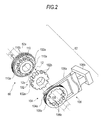
- Fig. 2 is a perspective view for explaining the configuration of the dog clutch.
- the dog clutch functions as a switching mechanism configured to switch the transmission between the torque-transmitting state and the non-torque-transmitting state between the first shaft (for example, the input shaft 12) and the second shaft (for example, the output shaft 20a) via the gear pair as a control object.
- the dog clutch includes the clutch ring, the hub, the sleeve, and a movable mechanism configured to move the sleeve.
- the clutch ring is supported so as to be rotatable about at least one of the first shaft and the second shaft, and fixes the first gears or the second gears concentrically so as to be capable of rotating.
- the hub is fixed to the first shaft or the second shaft configured to support the clutch ring.
- the sleeve fits to the hub so as to be movable in the axial direction on the first shaft or the second shaft to which the hub is fixed.
- a movable mechanism 106 moves the sleeve in the direction of the axis of the first shaft or the second shaft.
- the clutch ring includes a dog teeth provided so as to protrude toward the sleeve and configured to engage with the spline formed on the sleeve by a movement of the sleeve in the axial direction.
- Fig. 2 a detailed structure of the dog clutch will be described. Since the basic configurations of the first dog clutch 34, the second dog clutch 40, the third dog clutch 50, and the fourth dog clutch 62 illustrated in Fig. 1 are the same, the fourth dog clutch 62 will be described as a representative in conjunction with Fig. 2 .
- the fourth dog clutch 62 performs transmission between the torque-transmitting state and the non-torque-transmitting state of the A dog 60 in Fig. 1 .
- a clutch ring 100 which constitutes the fourth dog clutch 62 is rotatably supported around the input shaft 12, and a hub 102 is fixed around the input shaft 12.
- a sleeve 104 is fitted to an outer peripheral surface of the hub 102 so as to be movable on the outer peripheral surface of the hub 102 in a direction of an axial line 12a of the input shaft 12 by a movable member (for example, a fork member 106a) which constitutes part of the movable mechanism 106.
- a movable member for example, a fork member 106a
- a groove 104a is formed on an outer peripheral surface of the sleeve 104 in a circumferential direction to receive the fork member 106a.
- the sleeve 104 may be moved along the outer peripheral surface of the hub 102 in the direction of the axial line 12a.
- the fork member 106a is driven by an actuator 106b.
- a gear 52a of the second drive gear 52 is formed on an outer peripheral surface of the clutch ring 100.
- a dog teeth 110 configured to engage with a spline 108 formed on the sleeve 104 is formed on a side surface of the clutch ring 100 on the hub 102 side.
- the dog teeth 110 includes clutch front teeth 110a and a clutch rear teeth 110b formed on an outer peripheral surface of a projecting portion 100a protruding in a ring shape on the side surface of the clutch ring 100.
- the two clutch front teeth 110a are provided on the outer peripheral surface of the projecting portion 100a at positions, for example, 180 degrees apart from each other.
- the clutch rear teeth 110b are provided equidistantly between the two clutch front teeth 110a.
- twelve in total of the clutch front teeth 110a and the clutch rear teeth 110b are formed equidistantly on the outer peripheral surface of the projecting portion 100a as the dog teeth 110.
- the spline 108 engaging with the dog teeth 110 is formed on an inner peripheral surface of the ring-shaped sleeve 104. Therefore, the spline 108 includes twelve tooth grooves.
- the spline 108 includes high teeth 108a and low teeth 108b. Two of the high teeth 108a are provided on the inner peripheral surface of the sleeve 104 at positions, for example, 180 degrees apart from each other.
- the low teeth 108b are provided equidistantly between the two high teeth 108a.
- twelve in total of the high teeth 108a and the low teeth 108b are arranged equidistantly to form the spline 108 engaging with the dog teeth 110 formed equidistantly.
- the sleeve 104 fits on the outer peripheral surface of the hub 102 so as to be movable in the direction of the axial line 12a.
- two deep grooves 102a having a shape corresponding to the high teeth 108a of the sleeve 104 are formed at positions 180 degree apart from each other so as to be capable of receiving the high teeth 108a of the sleeve 104, and shallow grooves 102b having a shape corresponding to the low teeth 108b is formed equidistantly at position between the two deep grooves 102a on the outer peripheral surface of the hub 102.
- the clutch front teeth 110a is formed to have an outer diameter larger than the inner diameter of the high teeth 108a and smaller than the inner diameter of the low teeth 108b.
- the clutch rear teeth 110b is engageable with the teeth grooves of the spline 108 and are formed at a position retracted from the the clutch front teeth 110a in the direction away from the hub 102. With the respective teeth to have the height relationship therebetween, even though a difference between the rotational speeds of the clutch ring 100 and the sleeve 104 is present, the complete engagement therebetween may be achieved easily.
- the clutch rear teeth 110b are formed at positions retracted from the clutch front teeth 110a, when the sleeve 104 moves on the outer peripheral surface of the hub 102 toward the clutch ring 100, the high teeth 108a of the sleeve 104 come into contact with the clutch front teeth 110a of the clutch ring 100 first.
- the clutch front teeth 110a are formed at a distance of 180 degrees, even though there is significant difference in rotational speed between the clutch ring 100 and the sleeve 104, sufficient play is present between the respective teeth, so that the engagement between the clutch front teeth 110a and the high teeth 108a is easily achieved.
- the rotations of the clutch ring 100 and the sleeve 104 are synchronized by the engagement between the clutch front teeth 110a and the high teeth 108a.
- the clutch rear teeth 110b and the low teeth 108b formed equidistantly engage each other.
- the clutch ring 100 and the sleeve 104 engage completely each other.
- a mutual rotation of the sleeve 104 and the hub 102 is restricted and integrated by the engagement of the spline 108, and the hub 102 is fixed to the input shaft 12. Therefore, the clutch ring 100 is integrated with the input shaft 12 by a complete engagement between the clutch ring 100 and the sleeve 104.
- the second drive gear 52 integrated with the clutch ring 100 is fixed to the input shaft 12, and the transmission is switched from the non-torque-transmitting state to the torque-transmitting state in which the torque of the input shaft 12 can be transmitted to the second drive gear 52.
- the fourth dog clutch 62 in Fig. 2 has a configuration in which the switching operation of the A dog 60 only, that is, a switching operation of a single dog is performed.
- the first dog clutch 34, the second dog clutch 40, and the third dog clutch 50 perform a switching operation between the torque-transmitting state and the non-torque-transmitting state for each of the two dogs.
- the clutch rings 100 are arranged on both sides of the hub 102.
- the sleeve 104 is controlled to switch the state among three states, namely, a state moving toward the clutch ring 100 on the left side of the hub 102, a state of moving toward the clutch ring 100 on the right side of the hub 102, and a neutral state of being positioned on the hub 102 in out of contact with the both clutch rings 100.
- the clutch ring 100 integrated with the first driven gear 22 is arranged on the left side of the hub 102
- the clutch ring 100 integrated with the fifth driven gear 24 is arranged on the right side of the hub 102.
- the automatic transmission apparatus 10 is applied to the hybrid vehicle using the internal combustion engine 16 and the motor generator 18 as a drive source.
- a transmission state suitable for the traveling state is achieved by a drive control of the internal combustion engine 16 and the motor generator 18 by the ECU 92 and a switching control of the respective dogs.
- either one of the first driven gear 22, the fifth driven gear 24, the second driven gear 26, and the fourth driven gear 28 is fixed to the output shaft 20a by either one of the first dog clutch 34 or the second dog clutch 40, or either one of the third driven gear 42 and the driven gear for reverse travel 44 is fixed to the output shaft 20b by the third dog clutch 50. Consequently, control using a drive force of at least one of the internal combustion engine 16 and the motor generator 18 is realized.
- the automatic transmission apparatus 10 of the embodiment has options of not only a drive form using only the internal combustion engine 16 as a drive source when traveling the vehicle and a drive force using only the motor generator 18 as a drive source, but also a cooperative control mode using both of the internal combustion engine 16 and the motor generator 18 as the drive sources.
- a cooperative control mode using both of the internal combustion engine 16 and the motor generator 18 as the drive sources.
- the internal combustion engine 16 and the motor generator 18 are brought into a driving state and the clutch 14 is brought into the connecting state.
- the first dog 30 is switched to the torque-transmitting state by the first dog clutch 34
- the second dog 36 is switched to the torque transmitting state by the second dog clutch 40. Consequently, the torque of the internal combustion engine 16 is transmitted to the input shaft 12 via the clutch 14, and rotates the first/reverse travel drive gear 56 fixed to the input shaft 12. Then the first/reverse travel drive gear 56 rotates the first driven gear 22 fixed to the output shaft 20a by the first dog 30 and transmits the torque of the internal combustion engine 16 to the output shaft 20a in accordance with the gear ratio determined by the first gear pair 64.
- the torque of the motor generator 18 is transmitted to the fourth drive gear 54 which is freely rotated in accordance with the predetermined gear ratio and further rotates the second drive gear 52 integrated therewith.
- the second drive gear 52 rotates the second driven gear 26. Since the second driven gear 26 is fixed to the output shaft 20a by the second dog 36, the torque of the motor generator 18 is transmitted to the output shaft 20a in accordance with the gear ratio of the gears in the route of transmission such as the second gear pair 66. Therefore, both the torque of the internal combustion engine 16 and the torque of the motor generator 18 are transmitted to the output shaft 20a, and the output gear 76a is rotated.
- the torque transmitted to the output gear 76a is transmitted toward the differential apparatus 78, in other words, to the drive wheel side via the ring gear 80 to enable the traveling of the vehicle. The same applies to the torque transmission in the case where the vehicle is traveled by using other gear pairs.
- Power is generated by using the drive force of the internal combustion engine 16 when the vehicle is stopped by the control of the dog clutch, and the battery for driving the motor generator 18 may be charged.
- the first dog clutch 34, the second dog clutch 40, and the third dog clutch 50 are brought into a neutral state, and the second drive gear 52 and the fourth drive gear 54 are fixed to the input shaft 12 by the fourth dog clutch 62.
- the clutch 14 is brought into the connecting state. Consequently, the input shaft 12 is rotated by the torque of the internal combustion engine 16 and, in association therewith, the fourth drive gear 54 is rotated.
- the output shaft 82 of the motor generator 18 engages with the fourth drive gear 54 via the idle gear 86, the output shaft 82 of the motor generator 18 is rotated by the internal combustion engine 16, and functions as a motor generator. In other words, a state or generating power is assumed when the vehicle is stopped.
- the internal combustion engine 16 in a stopped state is started by the motor generator 18 by the control of the dog clutch.
- the second drive gear 52 and the fourth drive gear 54 are fixed to the input shaft 12 by the fourth dog clutch 62.
- the first dog clutch 34, the second dog clutch 40, and the third dog clutch 50 are brought into the neutral state, and the clutch 14 is brought into the connecting state.
- the motor generator 18 is driven in this state, the fourth drive gear 54 in the stopped state can be rotated.
- the internal combustion engine 16 can be started by rotating the input shaft 12 in the stopped state and rotating a crankshaft of the internal combustion engine 16 via the clutch 14. This configuration allows a starter apparatus for the internal combustion engine 16 to be omitted and contributes to simplification of the configuration and a reduction in cost.
- the torque of the internal combustion engine 16 passes through the input shaft 12 via the first gear pair 64 including the first/reverse travel drive gear 56 and the first driven gear 22, and is further transmitted to the reverse travel gear pair 74 including the first driven gear 22 and the driven gear for reverse travel 44. Consequently, the driven gear for reverse travel 44 fixed to an output gear 76b by the dog for reverse travel 48 rotates in a direction opposite to the direction of rotation of the input shaft 12, and cause the vehicle to move rearward.
- the torque of the internal combustion engine 16 is transmitted to the fourth drive gear 54 to rotate the output shaft 82 of the motor generator 18. In other words, power generation or assist can be performed during the reverse travel control.
- the automatic transmission apparatus 10 of the embodiment includes a plurality of gear pairs having different gear ratios, and transmission is switched between the torque-transmitting state in which the torque can be transmitted from one gear pair to another, and the non-torque-transmitting state in which the torque is not transmitted by the dog clutch.
- the gear pairs having different gear ratio between the input shaft and the output shaft are brought into the torque-transmitting state in which the torque can be transmitted, a relative rotation between the input shaft and the output shaft is disabled. In other words, the parking state in which the output shaft is locked is achieved.
- the dog teeth of the dog clutch and the high teeth or the low teeth of the sleeve are aligned in phase, so that the translation to the parking state may become impossible.
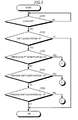
- a shift lever position of the embodiment is categorized, for example “P: parking” “R: reverse” “N: neutral”, and “D: drive”, and “D” further includes a neutral position effected in the case of shift-up "+” and shift-down "-" are selected by a manual operation.
- the ECU 92 confirms whether or not the ignition switch is turned OFF at a constant control cycle when the ignition switch (IG-SW) of the vehicle is ON (N in S100).
- the processes to be performed for establishing the parking state in which a traveling gear of the automatic transmission apparatus 10 is used depending on the cases, that is, in the case where the ignition switch is turned OFF (Y in S100), that is, in the case where a driver does not have a willing to make the vehicle travel is sorted out.
- the ECU 92 detects whether the shift lever position is shifted to "P". If the shift lever position is not shifted to "P", it is determined that the driver does not have a willing to park the vehicle (parking), and the flow is stopped once (N in S102).
- the ECU 92 proceeds to Process A in the flowchart in Fig. 4 , which will be descried later, in the case where the fact that the shift lever position is shifted to "P" (Y in S102), and the shift lever position immediately before the shift to "P" (previous time) is “N" (Y in S104). In contrast, in the case where the shift lever position immediately before the shift to "P" is not “N” in S104 (N in S104) and is "D" (Y in S106), the procedure goes to Process B in a flowchart in Fig. 7 , which will be described later.
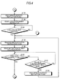
- Fig. 4 is a flowchart for explaining process A in the case where the shift lever position is "N" immediate (previous time) before the shift to "P" in S104, in the flowchart in Fig. 3 .
- the respective dog clutches of the automatic transmission apparatus 10 are all in the non-torque-transmitting state (neutral).
- the ECU 92 issues a minute rotation instruction to the motor generator 18 (S120). For example, the ECU 92 issues an instruction to rotate at 10 rpm.
- the clutch front teeth 110a and the high teeth 108a is disengaged from a state of engagement at positions adjacent to each other. In other words, in a state in which a phase difference between the clutch front teeth 110a and the high teeth 108a is small, and an attempt is made to engage the clutch front teeth 110a and the high teeth 108a, the phases may be aligned and hence the engagement may not be achieved.
- the fourth drive gear 54 and the second drive gear 52 in the state of being rotatable are minutely rotated by the motor generator 18 to provide the clutch front teeth 110a and the high teeth 108a with a phase difference in advance, and therefore, a probability that the engagement is not achieved due to an alignment in phase is reduced.
- the ECU 92 issues an A dog engagement instruction to the actuator 106b that drives the fork member 106a of the fourth dog clutch 62 and performs dog engagement control (S122) in order to switch the A dog 60 into the torque-transmitting state.
- Whether or not the fourth dog clutch 62 is completely engaged may be detected by whether or not the fork member 106a of the movable mechanism 106 moves to a position where the engagement between the clutch rear teeth 110b and the low teeth 108b is completed, that is, on the basis of the amount of movement. Since the minute rotation of the motor generator 18 is performed continuously, the dog engagement control for moving the fork member 106a is continued until the A dog 60 is brought into the torque-transmitting state (completion of A dog engagement) (N in S124). In contrast, when the A dog 60 is brought into the torque-transmitting state (Y in S124), the ECU 92 releases the minute rotation instruction of the motor generator 18 (S126).
- the ECU 92 issues an instruction to change the state of the first dog 30 to the torque-transmitting state (the first dog engagement instruction) to the actuator 106b that controls the fork member 106a of the first dog clutch 34 (S128). Then the ECU 92 proceeds to process D shown by the flowchart in Fig. 5 in the case where the it is recognized that the first dog 30 is brought into the torque-transmitting state (the state in which the first dog engagement is completed), that is, the engagement between the clutch rear teeth 110b on the first dog 30 side of the first dog clutch 34 and the low teeth 108b of the sleeve 104 is completed (Y in S130) on the basis of the amount of movement of the fork member 106a of the first dog clutch 34. At this time point, one of the gear pairs is brought into the torque-transmitting state between the input shaft 12 and the output shaft 20a.
- the ECU 92 issues the minute rotation instruction to the motor generator 18 (S134).
- the first driven gear 22 makes a minute rotation via the input shaft 12 and the first/reverse travel drive gear 56 fixed to the input shaft 12 by the rotation of the motor generator 18.
- the phases of the dog teeth 110 of the first dog 30 and the high teeth 108a or the low teeth 108b of the sleeve 104 may be shifted. Subsequently, the procedure goes to S126, to release the minute rotation instruction of the motor generator 18 and to continue the dog engagement control of the first dog 30 in new phase conditions.
- the period of the failure of dog engagement of the first dog 30 is a predetermined period, for example, smaller than 1000 ms (N in S132), the procedure goes to S130 and the dog engagement control of the first dog 30 is continuously performed.
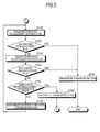
- Fig. 5 is a flowchart of a Process D continued from the state of completion of the dog engagement control of the first dog 30 in S130 in Fig. 4 .
- the ECU 92 performs a control of switching the second gear pair into the torque-transmitting state after the first gear pair 64 is switched to the torque-transmitting state. First of all, the ECU 92 issues the second dog 36 engagement instruction to the actuator 106b that causes the fork member 106a of the second dog clutch 40 to move (S140). Then, the ECU 92 detects whether the movement stroke of the fork member 106a of the second dog clutch 40 is within a predetermined range (S142).
- the ECU 92 detects whether a relationship of b ⁇ second dog Act stroke ⁇ a is established where a point of engagement between the clutch front teeth 110a of the clutch ring 100 of the second driven gear 26 and the high teeth 108a of the sleeve 104 (a point where the engagement between the gears starts) is a threshold value a, and a point of engagement between the clutch rear teeth 110b and the low teeth 108b is threshold value b.
- the ECU 92 releases the torque instruction (S144), and the flow is ended.
- the two gear pairs having different gear ratios are switched into the torque-transmitting state between the input shaft 12 and the output shaft 20a to disable a relative rotation between the input shaft 12 and the output shaft 20a.
- the parking state is achieved by using a traveling gear of the automatic transmission apparatus 10. Consequently, the gear for the parking and the mechanism or the actuator for causing the engagement thereof, which has been required in the related art, may be omitted, so that simplification, a reduction in size, and a reduction in cost of the configuration of the automatic transmission apparatus are achieved.
- the control using the second dog 36 is stopped once, and an attempt is made to control using other fourth dog 38 in the second dog clutch 40.
- the ECU 92 issues a fourth dog engagement instruction to the actuator 106b which drives the fork member 106a of the second dog clutch 40 to move the fork member 106a toward the fourth driven gear 28 (S146).
- the ECU 92 detects whether the movement stroke of the fork member 106a of the second dog clutch 40 falls within a predetermined range (S148). In this case, whether or not the relationship of b ⁇ fourth dog Act stroke ⁇ a is satisfied is detected.
- the sleeve 104 rotates, and the phase of the high teeth 108a of the sleeve 104 is displaced from the phase of the dog teeth 110 on the second driven gear 26 side and the phase of the dog teeth 110 on the fourth driven gear 28 side. Then, the procedure goes to S140, and an attempt is made to retry from the second dog engagement control.
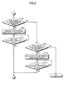
- Fig. 6 is a flowchart for explaining Process E in the case where the second dog and the fourth dog engagement control is failed for 2000 ms or more in the flow in Fig. 5 .
- the ECU 92 releases the complete engagement of the first dog 30 temporarily to form a play in engagement for the first driven gear 22 in a state of being already fixed to the output shaft 20a.
- the ECU 92 issues an instruction to make the first dog Act stroke to the threshold value a (mm) to the actuator 106b which drives the fork member 106a (S162).
- the ECU 92 waits until the first dog Act stroke of the fork member 106a of the first dog clutch 34 to be the threshold value a (N in S164), and when the threshold value a is reached (Y in S164), the procedure goes to S140 in Fig. 5 , where the procedure from Process D is retried.
- a play of approximately 180 degrees is present between the first driven gear 22 and the output shaft 20a at a portion of the first dog 30. Therefore, the torque may be supplied from the motor generator 18 to rotate the fourth driven gear 28 and the second driven gear 26 via the fourth drive gear 54 and the second drive gear 52.
- Process D by executing Process D, the phase of the dog teeth 110 corresponding to the second driven gear 26 with respect to the sleeve 104 of the second dog clutch 40, and the phase of the dog teeth 110 corresponding to the fourth driven gear 28 may be shifted. Consequently, a probability of succeed of the second dog engagement control or the fourth dog engagement control in Process D may be enhanced.
- the failure of the second dog and the fourth dog engagement control continues for 6000 ms or more in S160 (Y in S160), it means that, for example, the dog engagement control is not successful even though the control of releasing the complete engagement of the first dog 30 temporarily and Process D is performed by a plurality of time.
- the failure of the second dog and the fourth dog engagement control continues for a duration from 6000 ms inclusive to 10000 ms exclusive (N in S168)
- the complete engagement of the A dog 60 is temporarily released to form a play in engagement for the second drive gear 52 and the fourth drive gear 54 in a state of being already fixed to the input shaft 12.
- the ECU 92 issues an instruction to make the A dog Act stroke to the threshold value a (mm) to the actuator 106b which drives the fork member 106a (S170). Then, the ECU 92 waits until the A dog Act stroke of the fork member 106a of the fourth dog clutch 62 to be the threshold value a (N in S172), and when the threshold value a is reached (Y in S172), the procedure goes to S140 in Fig. 5 , where the procedure from Process D is retried.
- the ECU 92 recognizes that the establishment of the parking state is difficult by using the traveling gear of the automatic transmission apparatus 10 and terminates this process. In this case, it is preferable the fact that the establishment of the parking state by using the traveling gear of the automatic transmission apparatus 10 cannot be achieved is notified to the driver as an alarm to encourage the driver to operate a parking brake apparatus provided on the wheel side reliably.
- the dog engagement control may be completed efficiently for a short time by determining the priority of dog engagement control and the priority of releasing the engagement between the clutch rear teeth 110b and the low teeth 108b where the torque-transmitting state is already established temporarily for each of the dog clutches and achieving the engagement only between the clutch front teeth 110a and the high teeth 108a, and executing the dog engagement control in order of priority.
- Fig. 7 is a flowchart for explaining Process B in the case where the shift lever position is at "D" immediately before being shifted to "P" in S106 in Fig. 3 .
- the vehicle on which the automatic transmission apparatus 10 of the embodiment is mounted is configured to maintain the state of the gear of the automatic transmission apparatus 10 as is when the vehicle is stopped with the shift lever positioned at "D".
- the state in which the first gear pair 64 is switched to the torque-transmitting state is maintained as-is so as to allow the drive force of the internal combustion engine 16 to be transmitted to the output shaft 20a.
- the state in which the second gear pair 66 is switched to the torque-transmitting state is maintained as-is so as to allow the drive force of the motor generator 18 to be transmitted to the output shaft 20a.
- the first dog 30 and the second dog 36 are still switched to the torque-transmitting state. Therefore, the first driven gear 22 and the second driven gear 26 are in the state of being completely fixed to the output shaft 20a.
- the process B starts a process of switching the A dog in the non-torque-transmitting state to the torque-transmitting state on the presumption that the first dog 30 and the second dog 36 are in the torque transmitting state.
- the ECU 92 issues an instruction of an A dog engagement process to the actuator 106b configured to drive the fork member 106a of the fourth dog clutch 62 (S180). Then the ECU 92 detects whether the movement stroke of the fork member 106a falls within a predetermined range (S182).
- the ECU 92 detects whether or not a relationship of b ⁇ A dog Act stroke ⁇ a is established where a point of engagement between the clutch front teeth 110a of the clutch ring 100 of the second drive gear 52 and the high teeth 108a of the sleeve 104 (a point where the engagement between the gears starts) is a threshold value a, and a point of engagement between the clutch rear teeth 110b and the low teeth 108b is a threshold value b.
- the ECU 92 releases the torque instruction (S184) and the flow is ended.
- the two gear pairs having different gear ratios are switched into the torque-transmitting state between the input shaft 12 and the output shaft 20a to disable a relative rotation between the input shaft 12 and the output shaft 20a.
- the parking state is achieved by using a traveling gear of the automatic transmission apparatus 10.
- the ECU 92 issues an instruction of generation of the minute torque to the motor generator 18 (S188), and the procedure goes to S182.
- the direction of generation of the torque may either be the positive direction or the negative direction.
- the positive and negative may be output alternatively.
- the input shaft 12 and the output shaft 20a are in the torque-transmitting state in the first gear pair 64, and the output shaft 20a and the second driven gear 26 are fixed. However, slight plays are present in the respective engagements.
- the second drive gear 52 and the fourth drive gear 54 also have a probability of making a minute rotation. Consequently, the phases of the high teeth 108a of the A dog 60 and the clutch front teeth 110a of the dog teeth 110 on the second drive gear 52 side are displaced, and a probability of success of the dog engagement control of the A dog 60 is increased.
- the ECU 92 issues an N disengagement instruction for disengaging the second dog 36 and bringing the same into the neutral state to the second dog clutch 40 (S190).
- the second driven gear 26 fixed already to the output shaft 20a is brought into a rotatable state once, and then the second drive gear 52 is rotated by the motor generator 18 via the fourth drive gear 54. Consequently, the phases of the high teeth 108a of the A dog 60 and the clutch front teeth 110a of the dog teeth 110 on the second drive gear 52 side are displaced, so that the engaged state is easily achieved.
- the ECU 92 waits for the second dog clutch 40 being brought into the neutral state (N in S192), and when the second dog clutch 40 is brought into the neutral state (Y in S192), issues a minute rotation instruction to the motor generator 18. Accordingly, the A dog 60 is brought into a state of being engaged easily. Subsequently, the ECU 92 issues an instruction to execute the dog engagement control of the A dog 60 to the actuator 106b of the fork member 106a which drives the fourth dog clutch 62 (S196). Then, the ECU 92 waits for the dog engagement control of the A dog 60 being completed (N in S198), and when the dog engagement control of the A dog 60 is completed (Y in S198), the procedure goes to Process D illustrated in Fig.
- the parking state may be established quickly by performing the control by utilizing the fact that the gear pair on the low-speed side is in the torque-transmitting state when the vehicle stops.
- Fig. 8 is a flowchart for explaining Process C in a case where the shift lever position is at "R" immediately before being shifted to "P" in S108 in Fig. 3 .
- the gear at the time of reverse travel is assumed to be in the state in which the A dog 60 and the dog for reverse travel 48 have been switched to the torque-transmitting state when the vehicle is stopped.
- the ECU 92 issues an instruction to perform a dog for reverse travel N disengagement control, which is control to disengage the dog for reverse travel 48 with respect to the actuator 106b to achieve the neutral state, to the fork member 106a configured to drive the fork member 106a of the third dog clutch 50 (S200). Then, the ECU 92 waits for the dog for reverse travel 48 being brought into the neutral state (N in S202), and when the dog for reverse travel 48 is brought into the neutral state (Y in S202), issues a minute rotation instruction to the motor generator 18 (S194), so as to enhance a probability that the phases of the gears to be engaged by the dog engagement control of the first dog clutch 34 and the second dog clutch 40 are displaced. Subsequently, as indicated by reference sing F in Fig. 4 , the procedure goes to S126, and the ECU 92 executes the dog engagement controls of the first dog 30, the second dog 36, or the fourth dog 38.
- a dog for reverse travel N disengagement control which is control to disengage the dog for reverse
- the parking state in which the wheels side is prevented from moving by using the gears for traveling may be established by bringing at least two of the gear pairs having different gear ratios into the torque-transmitting state between the input shaft 12 and the output shaft 20a.
- the input shaft 12 and the output shaft 20a are brought into a locked state in which relative rotation cannot be performed due to the difference in gear ratio between at least the two gear pairs.
- the parking state in which neither the input shaft 12 nor the output shaft 20a can be rotated is achieved.
- the automatic transmission apparatus having a parking function is achieved although a specific configuration for parking is omitted, so that a reduction in size, simplification, and a reduction in cost of the automatic transmission apparatus are achieved consequently.
- the dog clutches are engaged in accordance with the predetermined priority when a plurality of gear pairs having different gear ratios are switched into the torque-transmitting state, the plurality of gear pairs having different gear ratios may be switched to the torque-transmitting state efficiently.
- the configuration illustrated in Fig. 1 is an example only, and a configuration in which the output shafts 20a and 20b are present with respect to the input shaft 12 has been described thus far.
- the output shaft may be composed of one output shaft, and the same advantages as the embodiment described above are achieved.
- the example in which the automatic transmission apparatus 10 includes five gears for forward travel and one gear for reverse travel has been described.
- the configuration of the transmission gears may be selected as needed, and the same effects as the embodiment disclosed here can be obtained as long as the configuration includes at least two gear pairs having different gear ratios.
- the example including the first gear pair 64, the second gear pair 66, and the fourth gear pair 70 has been described as the gear pairs having different gear ratios.
- the same effects as the embodiment may be provided even though other gear ratios are used as long as the gear ratios are different.
- the arrangement of the dog clutch may be changed as needed as long as the switching of the respective gear pairs between the torque-transmitting state and the non-torque-transmitting state may be changed as needed.
- the first dog clutch 34 may be used for switching the transmission between the first/reverse travel drive gear 56 and the third/fifth drive gear 58.
- the configuration in which the motor generator 18 is driven to shift the phases when the phases of the dog teeth of the dog clutch and the high teeth or the low teeth are aligned has been described.
- an external supply torque may be provided by utilizing the rotation of the internal combustion engine 16 as means for shifting the phases.
- the gear 52a of the second drive gear 52 is formed on the outer peripheral surface of the clutch ring 100 has been described.
- the clutch ring may be fixed integrally to the side surface of the second drive gear 52, which is rotatable with respect to the input shaft 12, so as to be coaxial therewith.
Landscapes
- Engineering & Computer Science (AREA)
- General Engineering & Computer Science (AREA)
- Mechanical Engineering (AREA)
- Control Of Transmission Device (AREA)
- Mechanical Operated Clutches (AREA)
- Chemical & Material Sciences (AREA)
- Combustion & Propulsion (AREA)
- Transportation (AREA)
Abstract
Description
- This disclosure relates to an automatic transmission apparatus.
- Some vehicles have a parking mechanism used when the vehicle is stopped for maintaining a stopped state. For example, among vehicles having an automatic transmission, those having the parking mechanism configured to switch an output shaft of the automatic transmission between a locked state which prohibits rotation and an unlocked state which allows rotation are known (e.g.
JP4400652B - The parking mechanism provided on the automatic transmission is generally configured to move a position of a movable claw member for parking provided on a vehicle body side by an actuator or the like and realize the locked state engaging a parking gear fixed to the output shaft of the automatic transmission and an unlocked state being disengaged therewith. In the field of vehicles, a reduction in size, simplification, a reduction in cost, and the like of components are required. Therefore, the parking mechanism is preferably reviewed as one of means of realizing such requirements.
- An automatic transmission apparatus related to an embodiment disclosed here includes: a plurality of first gears provided on a first shaft; a plurality of second gears provided on a second shaft and configured to engage with any one of the first gears to constitute gear pairs having different gear ratio; a switching mechanism configured to switch a transmission of each of the gear pairs between a transmitting state in which a torque is transmitted between the first shaft and the second shaft and a non-transmitting state in which the torque is not transmitted via the gear pair; and a gear control unit configured to control the switching mechanism while the vehicle is stopped, and switch at least two gear pairs to the transmitting state. In this configuration, by controlling at least two gear pairs having different gear ratio into the transmitting state which allows torque transmission, the first shaft and the second shaft are brought into a locked state in which relative rotation cannot be performed due to the difference in gear ratio between at least the two gear pairs. In other words, a parking state in which neither of the first shaft or the second shaft can rotate is achieved. Consequently, the automatic transmission apparatus having a parking function is achieved although a specific configuration for parking is omitted, so that a reduction in size, simplification, and a reduction in cost of the automatic transmission apparatus are achieved.
- The switching mechanism of the automatic transmission apparatus according to the embodiment disclosed here may include a clutch ring supported so as to be rotatable about an axis of at least one of the first shaft and the second shaft and configured to concentrically fix the first gears or the second gears so as to be rotatable; a hub fixed to the first shaft or the second shaft and configured to support the clutch ring; a sleeve configured to fit the hub so as to be movable on the first shaft or the second shaft having the hub fixed thereto in an axial direction; and a movable mechanism configured to move the sleeve in the axial direction. The clutch ring is provided so as to project toward the sleeve and includes dog teeth capable of engaging a spline formed on the sleeve by the movement of the sleeve in the axial direction. In this configuration, the parking function is realized by using a so-called dog clutch, which has a potential of realization of reduction in size, simplification, and reduction in cost, and thereby, reduction in size, simplification and reduction in cost of the automatic transmission apparatus is achieved as a consequence.
- The spline of the automatic transmission apparatus according to the embodiment disclosed here may include: a plurality of high teeth and a plurality of low teeth having a lower height than the high teeth, and the dog teeth may include clutch front teeth including the same number of teeth as the high teeth and having an outer diameter larger than an inner diameter of the high teeth and smaller than an inner diameter of the low teeth, and a clutch rear teeth capable of engaging with tooth grooves on the spline and formed at positions retracted from the clutch front teeth in the direction away from the hub. In this configuration, the high teeth of the spline of the sleeve engage with the clutch front teeth of the clutch ring, and then the low teeth of the spline and the clutch rear teeth of the clutch ring engage with each other. In other words, at the time when the high teeth and the clutch front teeth engage, there is a play in engagement. Consequently, engagement at the time of switching the transmitting state among the plurality of gear pairs is easily achieved.
- At least one of the gears which constitute the gear pairs of the automatic transmission apparatus of the embodiment disclosed here may be configured to be rotatable by an external supply torque when the vehicle is stopped. The external supply torque may be supplied, for example, by using a motor. The external supply torque may also be supplied by an internal combustion engine connected to the automatic transmission apparatus via a clutch, for example. In this configuration, even when the teeth phases of the spline of the sleeve and the clutch ring are aligned and hence cannot engage with each other, the phase can be changed, so that the spline and the teeth of the clutch ring can engage with each other.
- The gear control unit of the automatic transmission apparatus of the embodiment disclosed here may be configured to control the movable mechanism of the switching mechanism to cause the spline and the dog teeth to engage with each other according to a predetermined priority under the conditions that the vehicle satisfies predetermined parking conditions. In this configuration, engagement between the spline and the clutch ring may be achieved efficiently.
- In the automatic transmission apparatus of the embodiment disclosed here, the predetermined parking conditions may be that the remaining spline and dog teeth engage with each other on the premise that the vehicle is stopped with the spline corresponding to the low-speed side gear pair out of the gear pairs and the dog teeth engaging with each other. In this configuration, since engagement between the spline corresponding to the low-speed side gear pair having a higher likelihood of being in engagement when the vehicle is stopped and the dog teeth is utilized, control time until the parking state is established may be shortened.
- The gear control unit of the automatic transmission apparatus according to the embodiment disclosed here may be configured to adjust the engagement state by rotating at least one of the gears which constitute the gear pairs configured to switch the transmitting state according to the predetermined priority if the engagement between the spline and the dog teeth is not established. In this configuration, even when the spline of the sleeve and the dog teeth of the clutch ring are aligned in phase and hence cannot engage, the phase is changed according to the priority. Therefore, the spline and the dog teeth can be engaged efficiently.
- The foregoing and additional features and characteristics of this disclosure will become more apparent from the following detailed description considered with the reference to the accompanying drawings, wherein:
-
Fig. 1 is a schematic drawing illustrating a configuration of an automatic transmission apparatus according to an embodiment; -
Fig. 2 is a drawing illustrating a configuration of a dog clutch which constitutes part of the automatic transmission apparatus of the embodiment; -
Fig. 3 is a flowchart showing control performed by a gear control unit of the automatic transmission apparatus of the embodiment, and is a part of a flowchart showing a principal flow; -
Fig. 4 is a part of the flowchart of the automatic transmission apparatus of the embodiment carrying on from the flowchart inFig. 3 ; -
Fig. 5 is a part of the flowchart of the automatic transmission apparatus of the embodiment carrying on from the flowchart inFig. 4 ; -
Fig. 6 is a part of the flowchart of the automatic transmission apparatus of the embodiment carrying on from the flowchart inFig. 5 ; -
Fig. 7 is a part of the flowchart of the automatic transmission apparatus of the embodiment carrying on from the flowchart inFig. 3 ; and -
Fig. 8 is a part of the flowchart of the automatic transmission apparatus of the embodiment carrying on from the flowchart inFig. 3 . -
Fig. 1 is a schematic drawing illustrating a configuration centered on an automatic transmission apparatus (for example, automated transmission apparatus) 10 according to an embodiment. In the case of an exemplified configuration illustrated inFig. 1 , motive power of an internal combustion engine (for example, gasoline engine) 16 and motive power of amotor generator 18 are supplied to aninput shaft 12 of theautomatic transmission apparatus 10, for example, via a dry-type clutch 14. In other words, theautomatic transmission apparatus 10 of the embodiment is mounted on a hybrid vehicle. - The
automatic transmission apparatus 10 of the embodiment is a transmission having no synchronous mesh mechanism but an engaging mechanism referred to as "dog clutch" instead, and a plurality of gears being always in the engaged state. In this manner the automatic transmission apparatus including the dog clutch may be referred to as "dog transmission".Fig. 1 illustrates an example of the dog mission. Theautomatic transmission apparatus 10 of the embodiment is an example including oneinput shaft 12 and twooutput shafts input shaft 12 of the embodiment may be referred to as a first shaft. Theoutput shafts - The
output shaft 20a supports a first drivengear 22, a fifth drivengear 24, a second drivengear 26, and a fourth drivengear 28 rotatably on the shaft thereof. Theoutput shaft 20a includes afirst dog 30 configured to switch the transmission between a transmitting state (torque transmitting state) in which a torque is transmitted by fixing the first drivengear 22 to theoutput shaft 20a and a non-transmitting state (non-torque-transmitting state) in which the fixation is released and hence the torque cannot be transmitted. In the same manner, theoutput shaft 20a includes afifth dog 32 configured to switch the transmission between the torque transmitting state in which the fifth drivengear 24 is fixed to theoutput shaft 20a and the non-torque-transmitting state in which the fixation is released. Theoutput shaft 20a includes afirst dog clutch 34 configured to perform a switching operation to switch either one of thefirst dog 30 or thefifth dog 32 into the torque-transmitting state or both of thefirst dog 30 and thefifth dog 32 into the non-torque-transmitting state. In the same manner, theoutput shaft 20a includes asecond dog 36 configured to switch the transmission between the torque-transmitting state in which the second drivengear 26 is fixed to theoutput shaft 20a and the non-torque-transmitting state in which the fixation is released, and afourth dog 38 configured to switch the transmission between the torque-transmitting state in which the fourth drivengear 28 is fixed to theoutput shaft 20a and the non-torque-transmitting state in which the fixation is released. Theoutput shaft 20a includes asecond dog clutch 40 configured to perform a switching operation to switch either one of thesecond dog 36 or thefourth dog 38 into the torque-transmitting state or both of thesecond dog 36 and thefourth dog 38 into the non-torque-transmitting state. - The
output shaft 20b supports a third drivengear 42, and a driven gear forreverse travel 44 rotatably on the shaft thereof. Theoutput shaft 20b includes athird dog 46 configured to switch the transmission between the torque transmitting state in which the third drivengear 42 is fixed to theoutput shaft 20b, and the non-torque-transmitting state in which the fixation is released. In the same manner, theoutput shaft 20b includes a dog forreverse travel 48 configured to switch the transmission between the torque transmitting state in which the driven gear forreverse travel 44 is fixed to theoutput shaft 20b and the non-torque-transmitting state in which the fixation is released. Theoutput shaft 20b includes athird dog clutch 50 configured to perform a switching operation to switch either one of thethird dog 46 and the dog forreverse travel 48 into the torque-transmitting state or both of them into the non-torque-transmitting state. - The
input shaft 12 includes asecond drive gear 52, afourth drive gear 54, a first/reversetravel drive gear 56, and a third/fifth drive gear 58. In the configuration of this embodiment, the first/reversetravel drive gear 56 and the third/fifth drive gear 58 are fixed to theinput shaft 12. In contrast, thesecond drive gear 52 and thefourth drive gear 54 are rotatably supported on theinput shaft 12. In the configuration of the embodiment, thesecond drive gear 52 and thefourth drive gear 54 are integrated so that both can rotate upon reception of a power transmission of themotor generator 18 with thefourth drive gear 54, and can rotate integrally with theinput shaft 12. In contrast, theinput shaft 12 includes afourth dog clutch 62 configured to perform a switching operation provided with anA dog 60 configured to switch the transmission between the torque-transmitting state in which thesecond drive gear 52 is fixed to theinput shaft 12, and the non-torque-transmitting state in which the fixation is released. Therefore, when theA dog 60 is engaged with thesecond drive gear 52 by thefourth dog clutch 62, both of thesecond drive gear 52 and thefourth drive gear 54 are fixed to theinput shaft 12. In this embodiment, drive gears provided on theinput shaft 12 may be referred to as first gears, and driven gears provided on theoutput shafts - In the case of the
automatic transmission apparatus 10 inFig. 1 , the first drivengear 22 and the first/reversetravel drive gear 56 constitute afirst gear pair 64, the second drivengear 26 and thesecond drive gear 52 constitute asecond gear pair 66, and the third drivengear 42 and the third/fifth drive gear 58 constitute athird gear pair 68. The fourth drivengear 28 and thefourth drive gear 54 constitute afourth gear pair 70, and the fifth drivengear 24 and the third/fifth drive gear 58 constitute afifth gear pair 72. The driven gear forreverse travel 44 constitutes a pair with the first/reversetravel drive gear 56 via the first drivengear 22 and constitutes a reversetravel gear pair 74. - In this manner, the
first dog clutch 34, thesecond dog clutch 40, thethird dog clutch 50, and thefourth dog clutch 62 function as switching mechanisms for switching the transmission between the torque-transmitting state and the non-torque-transmitting state between the first shaft (for example, the input shaft 12) and the second shaft (for example, theoutput shaft 20a or theoutput shaft 20b) according to gear ratios determined from one gear pair to another via thefirst gear pair 64, thesecond gear pair 66, thethird gear pair 68, thefourth gear pair 70, thefifth gear pair 72, and the reversetravel gear pair 74. For example, the first drivengear 22 which has been rotatable by engaging thefirst dog 30 with the first drivengear 22 by thefirst dog clutch 34 is fixed to theoutput shaft 20a. Since the first/reversetravel drive gear 56 is fixed to theinput shaft 12, thefirst gear pair 64 is brought into the torque-transmitting state between theinput shaft 12 and theoutput shaft 20a in accordance with a predetermined gear ratio. In contrast, when the engagement between thefirst dog 30 and the first drivengear 22 is released by thefirst dog clutch 34, the first drivengear 22 is rotatable with respect to theoutput shaft 20a. Therefore, even though the first drivengear 22 is rotated by the first/reversetravel drive gear 56 fixed to theinput shaft 12, the first/reversetravel drive gear 56 only idles on theoutput shaft 20a, whereby thefirst gear pair 64 is brought into the non-torque-transmitting state between theinput shaft 12 and theoutput shaft 20a. - Output gears 76a and 76b are fixed to the
output shafts automatic transmission apparatus 10, respectively, and engage with aring gear 80 of adifferential apparatus 78, and a torque of theoutput shafts ring gear 80. - An
output gear 84 fixed to anoutput shaft 82 of themotor generator 18 engages with thefourth drive gear 54 via anidle gear 86. Therefore, themotor generator 18 is capable of rotating thefourth drive gear 54 and thesecond drive gear 52 simultaneously. InFig. 1 , theidle gear 86 includes arotation sensor 88, detects a real number of rotations of themotor generator 18, and utilizes the number of rotations for controlling themotor generator 18. A concentric slave cylinder (CSC) 90 configured to press a clutch cover of the clutch 14 is provided on theinput shaft 12. - The
automatic transmission apparatus 10 is provided with an electronic control unit (ECU) 92 configured to control theautomatic transmission apparatus 10. The ECU 92 functions as a gear control unit configured to control thefirst dog clutch 34, thesecond dog clutch 40, thethird dog clutch 50, and thefourth dog clutch 62, and switch the transmission between the torque-transmitting state and the non-torque-transmitting state. The ECU 92 may be configured as an integrative ECU configured to perform control of the clutch 14, themotor generator 18, theinternal combustion engine 16, and the like integrally. In contrast, in the modification, a mutual control between ECUs may be performed by providing a clutch ECU configured to control the clutch 14, a motor ECU configured to control themotor generator 18, and an engine ECU configured to control theinternal combustion engine 16 individually. An HVECU in which the engine ECU and the motor ECU are integrated may be provided. -
Fig. 2 is a perspective view for explaining the configuration of the dog clutch. - As described above, the dog clutch functions as a switching mechanism configured to switch the transmission between the torque-transmitting state and the non-torque-transmitting state between the first shaft (for example, the input shaft 12) and the second shaft (for example, the
output shaft 20a) via the gear pair as a control object. The dog clutch includes the clutch ring, the hub, the sleeve, and a movable mechanism configured to move the sleeve. The clutch ring is supported so as to be rotatable about at least one of the first shaft and the second shaft, and fixes the first gears or the second gears concentrically so as to be capable of rotating. The hub is fixed to the first shaft or the second shaft configured to support the clutch ring. The sleeve fits to the hub so as to be movable in the axial direction on the first shaft or the second shaft to which the hub is fixed. Amovable mechanism 106 moves the sleeve in the direction of the axis of the first shaft or the second shaft. Then, the clutch ring includes a dog teeth provided so as to protrude toward the sleeve and configured to engage with the spline formed on the sleeve by a movement of the sleeve in the axial direction. - Referring now to
Fig. 2 , a detailed structure of the dog clutch will be described. Since the basic configurations of thefirst dog clutch 34, thesecond dog clutch 40, thethird dog clutch 50, and thefourth dog clutch 62 illustrated inFig. 1 are the same, thefourth dog clutch 62 will be described as a representative in conjunction withFig. 2 . - The
fourth dog clutch 62 performs transmission between the torque-transmitting state and the non-torque-transmitting state of theA dog 60 inFig. 1 . A clutch ring 100 which constitutes thefourth dog clutch 62 is rotatably supported around theinput shaft 12, and ahub 102 is fixed around theinput shaft 12. Asleeve 104 is fitted to an outer peripheral surface of thehub 102 so as to be movable on the outer peripheral surface of thehub 102 in a direction of anaxial line 12a of theinput shaft 12 by a movable member (for example, afork member 106a) which constitutes part of themovable mechanism 106. Agroove 104a is formed on an outer peripheral surface of thesleeve 104 in a circumferential direction to receive thefork member 106a. In other words, even when thesleeve 104 rotates about theinput shaft 12, thesleeve 104 may be moved along the outer peripheral surface of thehub 102 in the direction of theaxial line 12a. Thefork member 106a is driven by anactuator 106b. - In this embodiment, a
gear 52a of thesecond drive gear 52 is formed on an outer peripheral surface of the clutch ring 100. Adog teeth 110 configured to engage with aspline 108 formed on thesleeve 104 is formed on a side surface of the clutch ring 100 on thehub 102 side. Thedog teeth 110 includes clutchfront teeth 110a and a clutchrear teeth 110b formed on an outer peripheral surface of a projectingportion 100a protruding in a ring shape on the side surface of the clutch ring 100. The two clutchfront teeth 110a are provided on the outer peripheral surface of the projectingportion 100a at positions, for example, 180 degrees apart from each other. On the other hand, for example, five of the clutchrear teeth 110b are provided equidistantly between the two clutchfront teeth 110a. In other words, twelve in total of the clutchfront teeth 110a and the clutchrear teeth 110b are formed equidistantly on the outer peripheral surface of the projectingportion 100a as thedog teeth 110. As described above, thespline 108 engaging with thedog teeth 110 is formed on an inner peripheral surface of the ring-shapedsleeve 104. Therefore, thespline 108 includes twelve tooth grooves. Thespline 108 includeshigh teeth 108a andlow teeth 108b. Two of thehigh teeth 108a are provided on the inner peripheral surface of thesleeve 104 at positions, for example, 180 degrees apart from each other. In contrast, for example, five of thelow teeth 108b are provided equidistantly between the twohigh teeth 108a. In other words, twelve in total of thehigh teeth 108a and thelow teeth 108b are arranged equidistantly to form thespline 108 engaging with thedog teeth 110 formed equidistantly. Thesleeve 104 fits on the outer peripheral surface of thehub 102 so as to be movable in the direction of theaxial line 12a. Therefore, twodeep grooves 102a having a shape corresponding to thehigh teeth 108a of thesleeve 104 are formed at positions 180 degree apart from each other so as to be capable of receiving thehigh teeth 108a of thesleeve 104, andshallow grooves 102b having a shape corresponding to thelow teeth 108b is formed equidistantly at position between the twodeep grooves 102a on the outer peripheral surface of thehub 102. - Here, a relationship among the clutch
front teeth 110a, the clutchrear teeth 110b, thehigh teeth 108a, and thelow teeth 108b is shown. The clutchfront teeth 110a is formed to have an outer diameter larger than the inner diameter of thehigh teeth 108a and smaller than the inner diameter of thelow teeth 108b. In contrast, the clutchrear teeth 110b is engageable with the teeth grooves of thespline 108 and are formed at a position retracted from the the clutchfront teeth 110a in the direction away from thehub 102. With the respective teeth to have the height relationship therebetween, even though a difference between the rotational speeds of the clutch ring 100 and thesleeve 104 is present, the complete engagement therebetween may be achieved easily. As described above, since the clutchrear teeth 110b are formed at positions retracted from the clutchfront teeth 110a, when thesleeve 104 moves on the outer peripheral surface of thehub 102 toward the clutch ring 100, thehigh teeth 108a of thesleeve 104 come into contact with the clutchfront teeth 110a of the clutch ring 100 first. In this case, since the clutchfront teeth 110a are formed at a distance of 180 degrees, even though there is significant difference in rotational speed between the clutch ring 100 and thesleeve 104, sufficient play is present between the respective teeth, so that the engagement between the clutchfront teeth 110a and thehigh teeth 108a is easily achieved. The rotations of the clutch ring 100 and thesleeve 104 are synchronized by the engagement between the clutchfront teeth 110a and thehigh teeth 108a. When thesleeve 104 moves on thehub 102 further toward the clutch ring 100, the clutchrear teeth 110b and thelow teeth 108b formed equidistantly engage each other. In other words, the clutch ring 100 and thesleeve 104 engage completely each other. A mutual rotation of thesleeve 104 and thehub 102 is restricted and integrated by the engagement of thespline 108, and thehub 102 is fixed to theinput shaft 12. Therefore, the clutch ring 100 is integrated with theinput shaft 12 by a complete engagement between the clutch ring 100 and thesleeve 104. In other words, thesecond drive gear 52 integrated with the clutch ring 100 is fixed to theinput shaft 12, and the transmission is switched from the non-torque-transmitting state to the torque-transmitting state in which the torque of theinput shaft 12 can be transmitted to thesecond drive gear 52. - The
fourth dog clutch 62 inFig. 2 has a configuration in which the switching operation of theA dog 60 only, that is, a switching operation of a single dog is performed. However, thefirst dog clutch 34, thesecond dog clutch 40, and thethird dog clutch 50 perform a switching operation between the torque-transmitting state and the non-torque-transmitting state for each of the two dogs. In this case, the clutch rings 100 are arranged on both sides of thehub 102. Then, thesleeve 104 is controlled to switch the state among three states, namely, a state moving toward the clutch ring 100 on the left side of thehub 102, a state of moving toward the clutch ring 100 on the right side of thehub 102, and a neutral state of being positioned on thehub 102 in out of contact with the both clutch rings 100. In the state of thefirst dog clutch 34, for example, the clutch ring 100 integrated with the first drivengear 22 is arranged on the left side of thehub 102, and the clutch ring 100 integrated with the fifth drivengear 24 is arranged on the right side of thehub 102. Therefore, when thesleeve 104 is moved toward the first drivengear 22 by afork member 106a, the first drivengear 22 is fixed to theoutput shaft 20a, and when thesleeve 104 is moved toward the fifth drivengear 24, the fifth drivengear 24 is fixed to theoutput shaft 20a. When thesleeve 104 is moved to the neutral state by thefork member 106a, neither the first drivengear 22 nor the fifth drivengear 24 are fixed to theoutput shaft 20a. It is the same for thesecond dog clutch 40 and thethird dog clutch 50. - As described above, the
automatic transmission apparatus 10 is applied to the hybrid vehicle using theinternal combustion engine 16 and themotor generator 18 as a drive source. A transmission state suitable for the traveling state is achieved by a drive control of theinternal combustion engine 16 and themotor generator 18 by the ECU 92 and a switching control of the respective dogs. For example, either one of the first drivengear 22, the fifth drivengear 24, the second drivengear 26, and the fourth drivengear 28 is fixed to theoutput shaft 20a by either one of thefirst dog clutch 34 or thesecond dog clutch 40, or either one of the third drivengear 42 and the driven gear forreverse travel 44 is fixed to theoutput shaft 20b by thethird dog clutch 50. Consequently, control using a drive force of at least one of theinternal combustion engine 16 and themotor generator 18 is realized. - The
automatic transmission apparatus 10 of the embodiment has options of not only a drive form using only theinternal combustion engine 16 as a drive source when traveling the vehicle and a drive force using only themotor generator 18 as a drive source, but also a cooperative control mode using both of theinternal combustion engine 16 and themotor generator 18 as the drive sources. Hereinafter, an example of the gear connection under the cooperative control will be described. - For example, an example of a motive power transmission in the case where the drive force of the
internal combustion engine 16 is transmitted by using thefirst gear pair 64, the drive force of themotor generator 18 is transmitted by using thesecond gear pair 66, that is, in the case where a first gear travel is performed by theinternal combustion engine 16 with an assist of themotor generator 18 will be described. - In this case, the
internal combustion engine 16 and themotor generator 18 are brought into a driving state and the clutch 14 is brought into the connecting state. As regards the dog, thefirst dog 30 is switched to the torque-transmitting state by thefirst dog clutch 34, and thesecond dog 36 is switched to the torque transmitting state by thesecond dog clutch 40. Consequently, the torque of theinternal combustion engine 16 is transmitted to theinput shaft 12 via the clutch 14, and rotates the first/reversetravel drive gear 56 fixed to theinput shaft 12. Then the first/reversetravel drive gear 56 rotates the first drivengear 22 fixed to theoutput shaft 20a by thefirst dog 30 and transmits the torque of theinternal combustion engine 16 to theoutput shaft 20a in accordance with the gear ratio determined by thefirst gear pair 64. In contrast, by bringing theA dog 60 into the non-torque-transmitting state, the torque of themotor generator 18 is transmitted to thefourth drive gear 54 which is freely rotated in accordance with the predetermined gear ratio and further rotates thesecond drive gear 52 integrated therewith. Thesecond drive gear 52 rotates the second drivengear 26. Since the second drivengear 26 is fixed to theoutput shaft 20a by thesecond dog 36, the torque of themotor generator 18 is transmitted to theoutput shaft 20a in accordance with the gear ratio of the gears in the route of transmission such as thesecond gear pair 66. Therefore, both the torque of theinternal combustion engine 16 and the torque of themotor generator 18 are transmitted to theoutput shaft 20a, and theoutput gear 76a is rotated. The torque transmitted to theoutput gear 76a is transmitted toward thedifferential apparatus 78, in other words, to the drive wheel side via thering gear 80 to enable the traveling of the vehicle. The same applies to the torque transmission in the case where the vehicle is traveled by using other gear pairs. - Power is generated by using the drive force of the
internal combustion engine 16 when the vehicle is stopped by the control of the dog clutch, and the battery for driving themotor generator 18 may be charged. For example, thefirst dog clutch 34, thesecond dog clutch 40, and thethird dog clutch 50 are brought into a neutral state, and thesecond drive gear 52 and thefourth drive gear 54 are fixed to theinput shaft 12 by thefourth dog clutch 62. Then, the clutch 14 is brought into the connecting state. Consequently, theinput shaft 12 is rotated by the torque of theinternal combustion engine 16 and, in association therewith, thefourth drive gear 54 is rotated. Since theoutput shaft 82 of themotor generator 18 engages with thefourth drive gear 54 via theidle gear 86, theoutput shaft 82 of themotor generator 18 is rotated by theinternal combustion engine 16, and functions as a motor generator. In other words, a state or generating power is assumed when the vehicle is stopped. - In addition, the
internal combustion engine 16 in a stopped state is started by themotor generator 18 by the control of the dog clutch. For example, when theinternal combustion engine 16 is stopped, thesecond drive gear 52 and thefourth drive gear 54 are fixed to theinput shaft 12 by thefourth dog clutch 62. In contrast, thefirst dog clutch 34, thesecond dog clutch 40, and thethird dog clutch 50 are brought into the neutral state, and the clutch 14 is brought into the connecting state. If themotor generator 18 is driven in this state, thefourth drive gear 54 in the stopped state can be rotated. In other words, theinternal combustion engine 16 can be started by rotating theinput shaft 12 in the stopped state and rotating a crankshaft of theinternal combustion engine 16 via the clutch 14. This configuration allows a starter apparatus for theinternal combustion engine 16 to be omitted and contributes to simplification of the configuration and a reduction in cost. - At the time of the reverse travel on the basis of the cooperative control, for example, the torque of the
internal combustion engine 16 passes through theinput shaft 12 via thefirst gear pair 64 including the first/reversetravel drive gear 56 and the first drivengear 22, and is further transmitted to the reversetravel gear pair 74 including the first drivengear 22 and the driven gear forreverse travel 44. Consequently, the driven gear forreverse travel 44 fixed to anoutput gear 76b by the dog forreverse travel 48 rotates in a direction opposite to the direction of rotation of theinput shaft 12, and cause the vehicle to move rearward. At this time, by switching theA dog 60 into the torque-transmitting state, the torque of theinternal combustion engine 16 is transmitted to thefourth drive gear 54 to rotate theoutput shaft 82 of themotor generator 18. In other words, power generation or assist can be performed during the reverse travel control. - In the
automatic transmission apparatus 10 configured as described above, a configuration of maintaining the stopped state of the vehicle, a configuration of maintaining a parking state, that is, the stopped state of the vehicle by achieving a parking state, that is, locking the output shaft will be described. - As described above, the
automatic transmission apparatus 10 of the embodiment includes a plurality of gear pairs having different gear ratios, and transmission is switched between the torque-transmitting state in which the torque can be transmitted from one gear pair to another, and the non-torque-transmitting state in which the torque is not transmitted by the dog clutch. For example, when both of the gear pairs having different gear ratio between the input shaft and the output shaft are brought into the torque-transmitting state in which the torque can be transmitted, a relative rotation between the input shaft and the output shaft is disabled. In other words, the parking state in which the output shaft is locked is achieved. - In conjunction with
Fig. 1 , an example in which theoutput shaft 20a is locked with respect to theinput shaft 12 by bringing thefirst gear pair 64 and thesecond gear pair 66 or thefourth gear pair 70 into the torque-transmitting state, for example, between theinput shaft 12 and theoutput shaft 20a will be described. As illustrated inFig. 2 , in the case where thedog teeth 110 of the dog clutch and thehigh teeth 108a or thelow teeth 108b that forms thespline 108 are aligned in phase, these teeth cannot engage with each other. If the gear pair on one of theinput shaft 12 and theoutput shaft 20a is switched to the torque-transmitting state, the phase of the gear pair on the other one of those may be determined correspondingly. Therefore, in the case where an attempt is made to engage the dog clutch in order to switch the gear pair on the other one of those into the torque-transmitting state, the dog teeth of the dog clutch and the high teeth or the low teeth of the sleeve are aligned in phase, so that the translation to the parking state may become impossible. - Referring now to flowcharts in
Fig. 3 to Fig. 8 , an example of realizing a parking state by using the gear pairs for traveling of theautomatic transmission apparatus 10 when the vehicle is stopped. In the embodiment, an example in which the two gear pairs are switched to the torque-transmitting state by controlling theA dog 60, thefirst dog 30, and thesecond dog 36 or thefourth dog 38 will be described. - The flowchart in
Fig. 3 describes the processes depending on the positions of the shift lever of the vehicle immediately before the stop of the vehicle (immediately before moving the shift lever to the parking range). A shift lever position of the embodiment is categorized, for example "P: parking" "R: reverse" "N: neutral", and "D: drive", and "D" further includes a neutral position effected in the case of shift-up "+" and shift-down "-" are selected by a manual operation. - The ECU 92 confirms whether or not the ignition switch is turned OFF at a constant control cycle when the ignition switch (IG-SW) of the vehicle is ON (N in S100). The processes to be performed for establishing the parking state in which a traveling gear of the
automatic transmission apparatus 10 is used depending on the cases, that is, in the case where the ignition switch is turned OFF (Y in S100), that is, in the case where a driver does not have a willing to make the vehicle travel is sorted out. First of all, the ECU 92 detects whether the shift lever position is shifted to "P". If the shift lever position is not shifted to "P", it is determined that the driver does not have a willing to park the vehicle (parking), and the flow is stopped once (N in S102). The ECU 92 proceeds to Process A in the flowchart inFig. 4 , which will be descried later, in the case where the fact that the shift lever position is shifted to "P" (Y in S102), and the shift lever position immediately before the shift to "P" (previous time) is "N" (Y in S104). In contrast, in the case where the shift lever position immediately before the shift to "P" is not "N" in S104 (N in S104) and is "D" (Y in S106), the procedure goes to Process B in a flowchart inFig. 7 , which will be described later. In the case where the shift lever position immediately before the shift to "P" is not "D" in S106 (N in S106), and is R (Y in S108), the procedure goes to process C in flowchart inFig. 8 , which will be described later. In the case where the shift lever position is not "R" (N in S108), it is determined that a system error occurs, and this flow is terminated once. -
Fig. 4 is a flowchart for explaining process A in the case where the shift lever position is "N" immediate (previous time) before the shift to "P" in S104, in the flowchart inFig. 3 . In this case, the respective dog clutches of theautomatic transmission apparatus 10 are all in the non-torque-transmitting state (neutral). - The ECU 92 issues a minute rotation instruction to the motor generator 18 (S120). For example, the ECU 92 issues an instruction to rotate at 10 rpm. For example, in the case where the
A dog 60 is switched from the torque-transmitting state to the non-torque-transmitting state before the vehicle is stopped, it means that the clutchfront teeth 110a and thehigh teeth 108a is disengaged from a state of engagement at positions adjacent to each other. In other words, in a state in which a phase difference between the clutchfront teeth 110a and thehigh teeth 108a is small, and an attempt is made to engage the clutchfront teeth 110a and thehigh teeth 108a, the phases may be aligned and hence the engagement may not be achieved. As described before, since the clutchfront teeth 110a and thehigh teeth 108a are arranged at positions 180 degrees apart from each other, there is a play of approximately 180 degrees. Therefore, thefourth drive gear 54 and thesecond drive gear 52 in the state of being rotatable are minutely rotated by themotor generator 18 to provide the clutchfront teeth 110a and thehigh teeth 108a with a phase difference in advance, and therefore, a probability that the engagement is not achieved due to an alignment in phase is reduced. - Subsequently, the ECU 92 issues an A dog engagement instruction to the
actuator 106b that drives thefork member 106a of thefourth dog clutch 62 and performs dog engagement control (S122) in order to switch theA dog 60 into the torque-transmitting state. - Whether or not the
fourth dog clutch 62 is completely engaged may be detected by whether or not thefork member 106a of themovable mechanism 106 moves to a position where the engagement between the clutchrear teeth 110b and thelow teeth 108b is completed, that is, on the basis of the amount of movement. Since the minute rotation of themotor generator 18 is performed continuously, the dog engagement control for moving thefork member 106a is continued until theA dog 60 is brought into the torque-transmitting state (completion of A dog engagement) (N in S124). In contrast, when theA dog 60 is brought into the torque-transmitting state (Y in S124), the ECU 92 releases the minute rotation instruction of the motor generator 18 (S126). - Subsequently, the ECU 92 issues an instruction to change the state of the
first dog 30 to the torque-transmitting state (the first dog engagement instruction) to theactuator 106b that controls thefork member 106a of the first dog clutch 34 (S128). Then the ECU 92 proceeds to process D shown by the flowchart inFig. 5 in the case where the it is recognized that thefirst dog 30 is brought into the torque-transmitting state (the state in which the first dog engagement is completed), that is, the engagement between the clutchrear teeth 110b on thefirst dog 30 side of thefirst dog clutch 34 and thelow teeth 108b of thesleeve 104 is completed (Y in S130) on the basis of the amount of movement of thefork member 106a of thefirst dog clutch 34. At this time point, one of the gear pairs is brought into the torque-transmitting state between theinput shaft 12 and theoutput shaft 20a. - In contrast, in the case where the first dog engagement in S130 is not completed (N in S130), or in the case where the failure of the dog engagement of the
first dog 30 continues for a predetermined period, 1000 ms or more (Y in S132), for example, the ECU 92 issues the minute rotation instruction to the motor generator 18 (S134). In this case, since theA dog 60 is already switched to the torque-transmitting state, thesecond drive gear 52 and thefourth drive gear 54 are fixed to theinput shaft 12. Therefore, the first drivengear 22 makes a minute rotation via theinput shaft 12 and the first/reversetravel drive gear 56 fixed to theinput shaft 12 by the rotation of themotor generator 18. In other words, the phases of thedog teeth 110 of thefirst dog 30 and thehigh teeth 108a or thelow teeth 108b of thesleeve 104 may be shifted. Subsequently, the procedure goes to S126, to release the minute rotation instruction of themotor generator 18 and to continue the dog engagement control of thefirst dog 30 in new phase conditions. In S132, the period of the failure of dog engagement of thefirst dog 30 is a predetermined period, for example, smaller than 1000 ms (N in S132), the procedure goes to S130 and the dog engagement control of thefirst dog 30 is continuously performed. -
Fig. 5 is a flowchart of a Process D continued from the state of completion of the dog engagement control of thefirst dog 30 in S130 inFig. 4 . - The ECU 92 performs a control of switching the second gear pair into the torque-transmitting state after the
first gear pair 64 is switched to the torque-transmitting state. First of all, the ECU 92 issues thesecond dog 36 engagement instruction to theactuator 106b that causes thefork member 106a of thesecond dog clutch 40 to move (S140). Then, the ECU 92 detects whether the movement stroke of thefork member 106a of thesecond dog clutch 40 is within a predetermined range (S142). In this case, with the stroke of thefork member 106a set as a second dog Act stroke with reference to the neutral position of thesecond dog clutch 40, the ECU 92 detects whether a relationship of b ≥ second dog Act stroke ≥ a is established where a point of engagement between the clutchfront teeth 110a of the clutch ring 100 of the second drivengear 26 and thehigh teeth 108a of the sleeve 104 (a point where the engagement between the gears starts) is a threshold value a, and a point of engagement between the clutchrear teeth 110b and thelow teeth 108b is threshold value b. If b ≥ second dog Act stroke ≥ a is established (Y in S142), at least the clutchfront teeth 110a and thehigh teeth 108a are displaced in phase, and a play of approximately 180 degrees is present between the clutchfront teeth 110a and thehigh teeth 108a. Therefore, even though the clutchrear teeth 110b and thelow teeth 108b are aligned in phase, the phase may be shifted within the play between the clutchfront teeth 110a and thehigh teeth 108a on the second drivengear 26 side, and hence the engagement between the clutchrear teeth 110b and thelow teeth 108b is easily achieved. In other words, the dog engagement process of thesecond dog 36 is completed. Therefore, in the case where the torque instruction is issued to themotor generator 18 when the dog engagement process of thesecond dog 36 is-completed, the ECU 92 releases the torque instruction (S144), and the flow is ended. At this time point, the two gear pairs having different gear ratios are switched into the torque-transmitting state between theinput shaft 12 and theoutput shaft 20a to disable a relative rotation between theinput shaft 12 and theoutput shaft 20a. In other words, the parking state is achieved by using a traveling gear of theautomatic transmission apparatus 10. Consequently, the gear for the parking and the mechanism or the actuator for causing the engagement thereof, which has been required in the related art, may be omitted, so that simplification, a reduction in size, and a reduction in cost of the configuration of the automatic transmission apparatus are achieved. - If b ≥ second dog Act stroke ≥ a is not established in S142 (N in S142), the control using the
second dog 36 is stopped once, and an attempt is made to control using otherfourth dog 38 in thesecond dog clutch 40. In other words, the ECU 92 issues a fourth dog engagement instruction to theactuator 106b which drives thefork member 106a of thesecond dog clutch 40 to move thefork member 106a toward the fourth driven gear 28 (S146). The ECU 92 detects whether the movement stroke of thefork member 106a of thesecond dog clutch 40 falls within a predetermined range (S148). In this case, whether or not the relationship of b ≥ fourth dog Act stroke ≥ a is satisfied is detected. If the relationship of b ≥ fourth dog Act stroke ≥ a is satisfied (Y in S148), at least the phases between the clutchfront teeth 110a of thefourth dog 38 and thehigh teeth 108a are shifted, and the play between the clutchfront teeth 110a and thehigh teeth 108a of approximately 180 degrees is present. Therefore, even though the phases of the clutchrear teeth 110b and thelow teeth 108b are aligned, the phases may be shifted within the range of the play between the clutchfront teeth 110a and thehigh teeth 108a on the fourth drivengear 28 side, whereby the engagement between the clutchrear teeth 110b and thelow teeth 108b is easily realized. In other words, the dog engagement process of thefourth dog 38 may be completed. In the case where the torque instruction is issued to themotor generator 18 when the dog engagement process of thefourth dog 38 is completed, the ECU 92 releases the torque instruction (S144) and the flow is ended. - In contrast, in the case where the relationship of b ≥ fourth dog Act stroke ≥ a is not satisfied in S148 (N in S148), and failure time from the start of the second dog and the fourth dog engagement control does not continue for 2000 ms or more (N in S150), an instruction of output of the minute torque is issued to the motor generator 18 (S152). In this case, the output torque generates a positive torque or a negative torque. Since the
A dog 60 and thefirst dog 30 are already switched to the torque-transmitting state, if themotor generator 18 generates the torque, theoutput shaft 20a rotates via theinput shaft 12 and thefirst gear pair 64, and thehub 102 of thesecond dog clutch 40 rotates. In other words, thesleeve 104 rotates, and the phase of thehigh teeth 108a of thesleeve 104 is displaced from the phase of thedog teeth 110 on the second drivengear 26 side and the phase of thedog teeth 110 on the fourth drivengear 28 side. Then, the procedure goes to S140, and an attempt is made to retry from the second dog engagement control. - In S150, in the case where the failure time from the start of the second dog and the fourth dog engagement control continues for 2000 ms or more (Y in S150), if the torque instruction is issued to the
motor generator 18, the ECU 92 release the torque instruction thereof (S154), and shifts to Process E which is a different handling shown in the flowchart inFig. 6 . -
Fig. 6 is a flowchart for explaining Process E in the case where the second dog and the fourth dog engagement control is failed for 2000 ms or more in the flow inFig. 5 . - In the case where the failure of the second dog and the fourth dog engagement control continues for a duration from 2000 ms inclusive to 6000 ms exclusive (N in S160), the ECU 92 releases the complete engagement of the
first dog 30 temporarily to form a play in engagement for the first drivengear 22 in a state of being already fixed to theoutput shaft 20a. In other words, in order to achieve the engagement only between the clutchfront teeth 110a of thedog teeth 110 and thehigh teeth 108a of thesleeve 104, the ECU 92 issues an instruction to make the first dog Act stroke to the threshold value a (mm) to theactuator 106b which drives thefork member 106a (S162). Then, the ECU 92 waits until the first dog Act stroke of thefork member 106a of thefirst dog clutch 34 to be the threshold value a (N in S164), and when the threshold value a is reached (Y in S164), the procedure goes to S140 inFig. 5 , where the procedure from Process D is retried. In this case, a play of approximately 180 degrees is present between the first drivengear 22 and theoutput shaft 20a at a portion of thefirst dog 30. Therefore, the torque may be supplied from themotor generator 18 to rotate the fourth drivengear 28 and the second drivengear 26 via thefourth drive gear 54 and thesecond drive gear 52. In other words, by executing Process D, the phase of thedog teeth 110 corresponding to the second drivengear 26 with respect to thesleeve 104 of thesecond dog clutch 40, and the phase of thedog teeth 110 corresponding to the fourth drivengear 28 may be shifted. Consequently, a probability of succeed of the second dog engagement control or the fourth dog engagement control in Process D may be enhanced. - In the case where the failure of the second dog and the fourth dog engagement control continues for 6000 ms or more in S160 (Y in S160), it means that, for example, the dog engagement control is not successful even though the control of releasing the complete engagement of the
first dog 30 temporarily and Process D is performed by a plurality of time. In this case, if the failure of the second dog and the fourth dog engagement control continues for a duration from 6000 ms inclusive to 10000 ms exclusive (N in S168), the complete engagement of theA dog 60 is temporarily released to form a play in engagement for thesecond drive gear 52 and thefourth drive gear 54 in a state of being already fixed to theinput shaft 12. In other words, in order to achieve the engagement only between the clutchfront teeth 110a and thehigh teeth 108a, the ECU 92 issues an instruction to make the A dog Act stroke to the threshold value a (mm) to theactuator 106b which drives thefork member 106a (S170). Then, the ECU 92 waits until the A dog Act stroke of thefork member 106a of thefourth dog clutch 62 to be the threshold value a (N in S172), and when the threshold value a is reached (Y in S172), the procedure goes to S140 inFig. 5 , where the procedure from Process D is retried. In this case, plays of approximately 180 degrees between thesecond drive gear 52 and thefourth drive gear 54 with respect to theinput shaft 12 are present at a portion of theA dog 60. Therefore, the torque may be supplied from themotor generator 18 to rotate the second drivengear 26 and the fourth drivengear 28 via thesecond drive gear 52 and thefourth drive gear 54. In other words, by re-executing Process D, the phase of thedog teeth 110 corresponding to the second drivengear 26 with respect to thesleeve 104 of thesecond dog clutch 40, and the phase of thedog teeth 110 corresponding to the fourth drivengear 28 may be shifted. Consequently, a probability of succeed of the second dog engagement control or the fourth dog engagement control in Process D may be enhanced. - In the case where the failure of the second dog and the fourth dog engagement control continues for 10000 ms or higher in S168 (Y in S168), for example, if the dog engagement control is not successful even though the control to release the complete engagement of the
A dog 60 temporarily and shift the phase is performed and Process D is performed by a plurality of times, the ECU 92 recognizes that the establishment of the parking state is difficult by using the traveling gear of theautomatic transmission apparatus 10 and terminates this process. In this case, it is preferable the fact that the establishment of the parking state by using the traveling gear of theautomatic transmission apparatus 10 cannot be achieved is notified to the driver as an alarm to encourage the driver to operate a parking brake apparatus provided on the wheel side reliably. In this manner the dog engagement control may be completed efficiently for a short time by determining the priority of dog engagement control and the priority of releasing the engagement between the clutchrear teeth 110b and thelow teeth 108b where the torque-transmitting state is already established temporarily for each of the dog clutches and achieving the engagement only between the clutchfront teeth 110a and thehigh teeth 108a, and executing the dog engagement control in order of priority. -
Fig. 7 is a flowchart for explaining Process B in the case where the shift lever position is at "D" immediately before being shifted to "P" in S106 inFig. 3 . The vehicle on which theautomatic transmission apparatus 10 of the embodiment is mounted is configured to maintain the state of the gear of theautomatic transmission apparatus 10 as is when the vehicle is stopped with the shift lever positioned at "D". In other words, the state in which thefirst gear pair 64 is switched to the torque-transmitting state is maintained as-is so as to allow the drive force of theinternal combustion engine 16 to be transmitted to theoutput shaft 20a. In the same manner, the state in which thesecond gear pair 66 is switched to the torque-transmitting state is maintained as-is so as to allow the drive force of themotor generator 18 to be transmitted to theoutput shaft 20a. In other words, thefirst dog 30 and thesecond dog 36 are still switched to the torque-transmitting state. Therefore, the first drivengear 22 and the second drivengear 26 are in the state of being completely fixed to theoutput shaft 20a. The process B starts a process of switching the A dog in the non-torque-transmitting state to the torque-transmitting state on the presumption that thefirst dog 30 and thesecond dog 36 are in the torque transmitting state. - The ECU 92 issues an instruction of an A dog engagement process to the
actuator 106b configured to drive thefork member 106a of the fourth dog clutch 62 (S180). Then the ECU 92 detects whether the movement stroke of thefork member 106a falls within a predetermined range (S182). In this case, with the stroke of thefork member 106a set as A dog Act stroke with reference to the neutral position (the position of the non-torque-transmitting state) of thefourth dog clutch 62, the ECU 92 detects whether or not a relationship of b ≥ A dog Act stroke ≥a is established where a point of engagement between the clutchfront teeth 110a of the clutch ring 100 of thesecond drive gear 52 and thehigh teeth 108a of the sleeve 104 (a point where the engagement between the gears starts) is a threshold value a, and a point of engagement between the clutchrear teeth 110b and thelow teeth 108b is a threshold value b. If b ≥ A dog Act stroke ≥ a is established (Y in S182), at least the clutchfront teeth 110a and thehigh teeth 108a are displaced in phase, and a play of approximately 180 degrees is present between the clutchfront teeth 110a and thehigh teeth 108a. Therefore, even though the phases of the clutchrear teeth 110b and thelow teeth 108b are aligned, the phases may be shifted within the range of the play between the clutchfront teeth 110a and thehigh teeth 108a on thesecond drive gear 52 side, whereby the engagement between the clutchrear teeth 110b and thelow teeth 108b is easily realized. In other words, the dog engagement process of theA dog 60 may be completed. In the case where the torque instruction is issued to themotor generator 18 when the dog engagement process of theA dog 60 is completed, the ECU 92 releases the torque instruction (S184) and the flow is ended. At this time point, the two gear pairs having different gear ratios are switched into the torque-transmitting state between theinput shaft 12 and theoutput shaft 20a to disable a relative rotation between theinput shaft 12 and theoutput shaft 20a. In other words, the parking state is achieved by using a traveling gear of theautomatic transmission apparatus 10. - In contrast, in the case where the relationship of b ≥ A dog Act stroke ≥ a is not satisfied (N in S182), and failure of the dog engagement control of the
A dog 60 does not continue for 1000 ms or more (N in S186), the ECU 92 issues an instruction of generation of the minute torque to the motor generator 18 (S188), and the procedure goes to S182. The direction of generation of the torque may either be the positive direction or the negative direction. The positive and negative may be output alternatively. In this case, theinput shaft 12 and theoutput shaft 20a are in the torque-transmitting state in thefirst gear pair 64, and theoutput shaft 20a and the second drivengear 26 are fixed. However, slight plays are present in the respective engagements. Therefore, when themotor generator 18 generates a minute torque, thesecond drive gear 52 and thefourth drive gear 54 also have a probability of making a minute rotation. Consequently, the phases of thehigh teeth 108a of theA dog 60 and the clutchfront teeth 110a of thedog teeth 110 on thesecond drive gear 52 side are displaced, and a probability of success of the dog engagement control of theA dog 60 is increased. - In contrast, when the failure of the dog engagement control of the
A dog 60 continues for 1000 ms or more, for example (Y in S186), the ECU 92 issues an N disengagement instruction for disengaging thesecond dog 36 and bringing the same into the neutral state to the second dog clutch 40 (S190). In other words, the second drivengear 26 fixed already to theoutput shaft 20a is brought into a rotatable state once, and then thesecond drive gear 52 is rotated by themotor generator 18 via thefourth drive gear 54. Consequently, the phases of thehigh teeth 108a of theA dog 60 and the clutchfront teeth 110a of thedog teeth 110 on thesecond drive gear 52 side are displaced, so that the engaged state is easily achieved. The ECU 92 waits for thesecond dog clutch 40 being brought into the neutral state (N in S192), and when thesecond dog clutch 40 is brought into the neutral state (Y in S192), issues a minute rotation instruction to themotor generator 18. Accordingly, theA dog 60 is brought into a state of being engaged easily. Subsequently, the ECU 92 issues an instruction to execute the dog engagement control of theA dog 60 to the actuator 106b of thefork member 106a which drives the fourth dog clutch 62 (S196). Then, the ECU 92 waits for the dog engagement control of theA dog 60 being completed (N in S198), and when the dog engagement control of theA dog 60 is completed (Y in S198), the procedure goes to Process D illustrated inFig. 5 , where an attempt is made to retry the dog engagement control of thesecond dog 36. In this manner, the parking state may be established quickly by performing the control by utilizing the fact that the gear pair on the low-speed side is in the torque-transmitting state when the vehicle stops. -
Fig. 8 is a flowchart for explaining Process C in a case where the shift lever position is at "R" immediately before being shifted to "P" in S108 inFig. 3 . In the case of the embodiment, the gear at the time of reverse travel is assumed to be in the state in which theA dog 60 and the dog forreverse travel 48 have been switched to the torque-transmitting state when the vehicle is stopped. - The ECU 92 issues an instruction to perform a dog for reverse travel N disengagement control, which is control to disengage the dog for
reverse travel 48 with respect to the actuator 106b to achieve the neutral state, to thefork member 106a configured to drive thefork member 106a of the third dog clutch 50 (S200). Then, the ECU 92 waits for the dog forreverse travel 48 being brought into the neutral state (N in S202), and when the dog forreverse travel 48 is brought into the neutral state (Y in S202), issues a minute rotation instruction to the motor generator 18 (S194), so as to enhance a probability that the phases of the gears to be engaged by the dog engagement control of thefirst dog clutch 34 and thesecond dog clutch 40 are displaced. Subsequently, as indicated by reference sing F inFig. 4 , the procedure goes to S126, and the ECU 92 executes the dog engagement controls of thefirst dog 30, thesecond dog 36, or thefourth dog 38. - In this manner, the parking state in which the wheels side is prevented from moving by using the gears for traveling may be established by bringing at least two of the gear pairs having different gear ratios into the torque-transmitting state between the
input shaft 12 and theoutput shaft 20a. In this configuration, by bringing at least two gear pairs having different gear ratio into the transmitting state which allows torque transmission, theinput shaft 12 and theoutput shaft 20a are brought into a locked state in which relative rotation cannot be performed due to the difference in gear ratio between at least the two gear pairs. In other words, the parking state in which neither theinput shaft 12 nor theoutput shaft 20a can be rotated is achieved. Therefore, the automatic transmission apparatus having a parking function is achieved although a specific configuration for parking is omitted, so that a reduction in size, simplification, and a reduction in cost of the automatic transmission apparatus are achieved consequently. As described in conjunction with the respective flowcharts, by bringing the dog clutches are engaged in accordance with the predetermined priority when a plurality of gear pairs having different gear ratios are switched into the torque-transmitting state, the plurality of gear pairs having different gear ratios may be switched to the torque-transmitting state efficiently. - In the embodiment described above, the configuration illustrated in
Fig. 1 is an example only, and a configuration in which theoutput shafts input shaft 12 has been described thus far. However, the output shaft may be composed of one output shaft, and the same advantages as the embodiment described above are achieved. In this embodiment, the example in which theautomatic transmission apparatus 10 includes five gears for forward travel and one gear for reverse travel has been described. However, the configuration of the transmission gears may be selected as needed, and the same effects as the embodiment disclosed here can be obtained as long as the configuration includes at least two gear pairs having different gear ratios. In the embodiment disclosed here, the example including thefirst gear pair 64, thesecond gear pair 66, and thefourth gear pair 70 has been described as the gear pairs having different gear ratios. However, the same effects as the embodiment may be provided even though other gear ratios are used as long as the gear ratios are different. In addition, the arrangement of the dog clutch may be changed as needed as long as the switching of the respective gear pairs between the torque-transmitting state and the non-torque-transmitting state may be changed as needed. For example, thefirst dog clutch 34 may be used for switching the transmission between the first/reversetravel drive gear 56 and the third/fifth drive gear 58. - In the embodiment described above, the configuration in which the
motor generator 18 is driven to shift the phases when the phases of the dog teeth of the dog clutch and the high teeth or the low teeth are aligned has been described. In another modification, an external supply torque may be provided by utilizing the rotation of theinternal combustion engine 16 as means for shifting the phases. In the example inFig. 2 , the example in which thegear 52a of thesecond drive gear 52 is formed on the outer peripheral surface of the clutch ring 100 has been described. However, the clutch ring may be fixed integrally to the side surface of thesecond drive gear 52, which is rotatable with respect to theinput shaft 12, so as to be coaxial therewith. - In the flowchart illustrated in
Fig. 6 , the example in which the engagement state of thefirst dog 30 and theA dog 60 is returned to the position of the threshold value a so that only the clutchfront teeth 110a and thehigh teeth 108a engage and the play is formed, thereby allowing another dog clutch to engage has been described. In this case, after another dog clutch is engaged, the engaged state of thefirst dog 30 and theA dog 60 may be returned so that the clutchrear teeth 110b and thelow teeth 108b engage with each other again. The respective flowcharts show an example of the flow of control, and the order or processing may be changed as needed as long as at least the two gear pairs having different gear ratios may be brought into the torque-transmitting state between theinput shaft 12 and theoutput shaft 20a, whereby the same advantages are achieved. - Although several embodiments of the invention has been described, these embodiments are intended for illustration only, and are not intended to limit the scope of the invention. These new embodiments may be implemented in other various modes, and various omissions, replacements, and modifications may be made without departing from the gist of the invention. These embodiments and modifications thereof are included in the scope and gist of the invention, and are included in the invention described in Claims and a range equivalent thereto.
- The principles, preferred embodiment and mode of operation of the present invention have been described in the foregoing specification. However, the invention which is intended to be protected is not to be construed as limited to the particular embodiments disclosed. Further, the embodiments described herein are to be regarded as illustrative rather than restrictive. Variations and changes may be made by others, and equivalents employed, without departing from the spirit of the present invention. Accordingly, it is expressly intended that all such variations, changes and equivalents which fall within the spirit and scope of the present invention as defined in the claims, be embraced thereby.
- It is explicitly stated that all features disclosed in the description and/or the claims are intended to be disclosed separately and independently from each other for the purpose of original disclosure as well as for the purpose of restricting the claimed invention independent of the composition of the features in the embodiments and/or the claims. It is explicitly stated that all value ranges or indications of groups of entities disclose every possible intermediate value or intermediate entity for the purpose of original disclosure as well as for the purpose of restricting the claimed invention, in particular as limits of value ranges.
Claims (7)
- An automatic transmission apparatus (10) comprising:a plurality of first gears (52, 54, 56, 58) provided on a first shaft (12);a plurality of second gears (22, 24, 26, 28, 42, 44) provided on a second shaft (20a, 20b), and configured to engage with any one of the first gears to constitute gear pairs having different gear ratio;a switching mechanism (34, 40, 50, 62) configured to switch each of the gear pairs between a transmitting state in which a torque is transmitted between the first shaft and the second shaft via the gear pairs and a non-transmitting state in which the torque is not transmitted; anda gear control unit (92) configured to control the switching mechanism while the vehicle is stopped, and switch at least two gear pairs to the transmitting state.
- The automatic transmission apparatus according to Claim 1,
wherein the switching mechanism includes:a clutch ring (100) supported so as to be rotatable about an axis of at least one of the first shaft and the second shaft and configured to concentrically fix the first gears or the second gears so as to be rotatable;a hub (102) fixed to the first shaft or the second shaft configured to support the clutch ring;a sleeve (104) configured to fit the hub so as to be movable on the first shaft or the second shaft having the hub fixed thereto in an axial direction; anda movable mechanism (106) configured to move the sleeve in the axial direction, andwherein the clutch ring is provided so as to project toward the sleeve and includes dog teeth (110) capable of engaging with a spline (104) formed on the sleeve by the movement of the sleeve in the axial direction. - The automatic transmission apparatus according to Claim 2,
wherein the spline includesa plurality of high teeth (108a) and a plurality of low teeth (108b) having a lower height than the high teeth, andthe dog teeth includes:clutch front teeth (110a) including the same number of teeth as the high teeth and having an outer diameter larger than an inner diameter of the high teeth and smaller than an inner diameter of the low teeth, andclutch rear teeth (110b) capable of engaging with tooth grooves on the spline and formed at positions retracted from the clutch front teeth in the direction away from the hub. - The automatic transmission apparatus according to Claim 2 or 3,
wherein at least one of gears which constitute the gear pair is rotatable by an external supply torque when the vehicle is stopped. - The automatic transmission apparatus according to Claim 3 or 4,
wherein the gear control unit controls the movable mechanism of the switching mechanism to cause the spline and the dog teeth to engage with each other according to a predetermined priority under the conditions that the vehicle satisfies predetermined parking conditions. - The automatic transmission apparatus according to Claim 5,
wherein the predetermined parking conditions are that the remaining spline and dog teeth engage with each other on the premise that the vehicle is stopped with the spline corresponding to the low-speed side gear pair out of the gear pairs and the dog teeth engaging with each other. - The automatic transmission apparatus according to Claim 5 or 6,
wherein with gear control unit adjusts the engagement state by rotating at least one of the gears which constitute the gear pairs configured to switch the transmitting state according to the predetermined priority if the engagement between the spline and the dog teeth is not established.
Applications Claiming Priority (1)
| Application Number | Priority Date | Filing Date | Title |
|---|---|---|---|
| JP2013193317A JP2015059604A (en) | 2013-09-18 | 2013-09-18 | Automatic transmission |
Publications (2)
| Publication Number | Publication Date |
|---|---|
| EP2851583A1 true EP2851583A1 (en) | 2015-03-25 |
| EP2851583B1 EP2851583B1 (en) | 2016-04-27 |
Family
ID=51298619
Family Applications (1)
| Application Number | Title | Priority Date | Filing Date |
|---|---|---|---|
| EP14180357.7A Not-in-force EP2851583B1 (en) | 2013-09-18 | 2014-08-08 | Automatic transmission apparatus |
Country Status (3)
| Country | Link |
|---|---|
| EP (1) | EP2851583B1 (en) |
| JP (1) | JP2015059604A (en) |
| CN (1) | CN104442748A (en) |
Families Citing this family (2)
| Publication number | Priority date | Publication date | Assignee | Title |
|---|---|---|---|---|
| CN106641237A (en) * | 2017-01-22 | 2017-05-10 | 山东科技大学 | AMT hydraulic gear shifting execution system having mechanical positioning function |
| CN109681540B (en) * | 2018-11-08 | 2025-12-30 | 吴有智 | Dual-mode switching clutch and its transmission application structure |
Citations (3)
| Publication number | Priority date | Publication date | Assignee | Title |
|---|---|---|---|---|
| JPH01312254A (en) * | 1988-06-08 | 1989-12-18 | Hino Motors Ltd | Automatic transmission |
| JP4400652B2 (en) | 2007-06-06 | 2010-01-20 | トヨタ自動車株式会社 | Parking mechanism |
| JP2010096190A (en) * | 2008-10-14 | 2010-04-30 | Daihatsu Motor Co Ltd | Dog clutch device |
Family Cites Families (2)
| Publication number | Priority date | Publication date | Assignee | Title |
|---|---|---|---|---|
| CN202531678U (en) * | 2012-04-23 | 2012-11-14 | 四川九龙机械有限公司 | Jaw type embedding structure of clutch |
| CN103277041B (en) * | 2013-05-28 | 2015-09-23 | 江苏德航工程机械装备有限公司 | A kind of spline type clutch transmission device |
-
2013
- 2013-09-18 JP JP2013193317A patent/JP2015059604A/en active Pending
-
2014
- 2014-08-08 EP EP14180357.7A patent/EP2851583B1/en not_active Not-in-force
- 2014-09-17 CN CN201410474716.5A patent/CN104442748A/en active Pending
Patent Citations (3)
| Publication number | Priority date | Publication date | Assignee | Title |
|---|---|---|---|---|
| JPH01312254A (en) * | 1988-06-08 | 1989-12-18 | Hino Motors Ltd | Automatic transmission |
| JP4400652B2 (en) | 2007-06-06 | 2010-01-20 | トヨタ自動車株式会社 | Parking mechanism |
| JP2010096190A (en) * | 2008-10-14 | 2010-04-30 | Daihatsu Motor Co Ltd | Dog clutch device |
Also Published As
| Publication number | Publication date |
|---|---|
| EP2851583B1 (en) | 2016-04-27 |
| JP2015059604A (en) | 2015-03-30 |
| CN104442748A (en) | 2015-03-25 |
Similar Documents
| Publication | Publication Date | Title |
|---|---|---|
| EP3475111B1 (en) | Hybrid driveline assembly | |
| JP5664764B2 (en) | Vehicle drive device | |
| US9573456B2 (en) | Power transmission apparatus for vehicle | |
| US8635923B2 (en) | Vehicle drive system | |
| US20110167957A1 (en) | Automatic dual-clutch transmission | |
| JPH1182734A (en) | Power transmission device for vehicles | |
| JP4029875B2 (en) | Vehicle control device | |
| WO2012127656A1 (en) | Vehicle drive apparatus | |
| RU2657587C1 (en) | Starting control device for a hybrid vehicle | |
| JP6372535B2 (en) | transfer | |
| KR101294090B1 (en) | Power transmission apparatus for vehicle | |
| JP2017154511A (en) | Driving device for vehicle | |
| EP2851583B1 (en) | Automatic transmission apparatus | |
| JP2016203898A (en) | Vehicle control device | |
| JP4566230B2 (en) | Drive device | |
| JP2013203260A (en) | Hybrid system | |
| JP2013060043A (en) | Power transmission device for vehicle | |
| CN112815049B (en) | Control device of power transmission mechanism | |
| CN111433065A (en) | Control device for transaxle | |
| KR101339248B1 (en) | Power transmission apparatus for vehicle | |
| CN107000570A (en) | The dynamical system for motor vehicles with the speed change transfer device including three epicyclic trains, the dynamical system in particular for hybrid vehicle | |
| US10393231B2 (en) | Automatic transmission and control method of automatic transmission | |
| JP2016061409A (en) | Hill hold device and hill hold method | |
| JP7803651B2 (en) | Method and system for controlling gearbox actuators in a hybrid propulsion vehicle transmission | |
| US12523262B2 (en) | Switchable clutch unit |
Legal Events
| Date | Code | Title | Description |
|---|---|---|---|
| PUAI | Public reference made under article 153(3) epc to a published international application that has entered the european phase |
Free format text: ORIGINAL CODE: 0009012 |
|
| 17P | Request for examination filed |
Effective date: 20140808 |
|
| AK | Designated contracting states |
Kind code of ref document: A1 Designated state(s): AL AT BE BG CH CY CZ DE DK EE ES FI FR GB GR HR HU IE IS IT LI LT LU LV MC MK MT NL NO PL PT RO RS SE SI SK SM TR |
|
| AX | Request for extension of the european patent |
Extension state: BA ME |
|
| R17P | Request for examination filed (corrected) |
Effective date: 20150923 |
|
| RBV | Designated contracting states (corrected) |
Designated state(s): AL AT BE BG CH CY CZ DE DK EE ES FI FR GB GR HR HU IE IS IT LI LT LU LV MC MK MT NL NO PL PT RO RS SE SI SK SM TR |
|
| GRAP | Despatch of communication of intention to grant a patent |
Free format text: ORIGINAL CODE: EPIDOSNIGR1 |
|
| RIC1 | Information provided on ipc code assigned before grant |
Ipc: F16D 11/10 20060101ALI20151023BHEP Ipc: B60K 6/48 20071001ALI20151023BHEP Ipc: F16H 61/00 20060101AFI20151023BHEP |
|
| INTG | Intention to grant announced |
Effective date: 20151126 |
|
| GRAS | Grant fee paid |
Free format text: ORIGINAL CODE: EPIDOSNIGR3 |
|
| GRAA | (expected) grant |
Free format text: ORIGINAL CODE: 0009210 |
|
| AK | Designated contracting states |
Kind code of ref document: B1 Designated state(s): AL AT BE BG CH CY CZ DE DK EE ES FI FR GB GR HR HU IE IS IT LI LT LU LV MC MK MT NL NO PL PT RO RS SE SI SK SM TR |
|
| REG | Reference to a national code |
Ref country code: GB Ref legal event code: FG4D |
|
| REG | Reference to a national code |
Ref country code: CH Ref legal event code: EP |
|
| REG | Reference to a national code |
Ref country code: AT Ref legal event code: REF Ref document number: 795177 Country of ref document: AT Kind code of ref document: T Effective date: 20160515 |
|
| REG | Reference to a national code |
Ref country code: IE Ref legal event code: FG4D |
|
| REG | Reference to a national code |
Ref country code: DE Ref legal event code: R096 Ref document number: 602014001686 Country of ref document: DE |
|
| REG | Reference to a national code |
Ref country code: FR Ref legal event code: PLFP Year of fee payment: 3 |
|
| REG | Reference to a national code |
Ref country code: LT Ref legal event code: MG4D |
|
| REG | Reference to a national code |
Ref country code: NL Ref legal event code: MP Effective date: 20160427 |
|
| REG | Reference to a national code |
Ref country code: AT Ref legal event code: MK05 Ref document number: 795177 Country of ref document: AT Kind code of ref document: T Effective date: 20160427 |
|
| PG25 | Lapsed in a contracting state [announced via postgrant information from national office to epo] |
Ref country code: NL Free format text: LAPSE BECAUSE OF FAILURE TO SUBMIT A TRANSLATION OF THE DESCRIPTION OR TO PAY THE FEE WITHIN THE PRESCRIBED TIME-LIMIT Effective date: 20160427 |
|
| PG25 | Lapsed in a contracting state [announced via postgrant information from national office to epo] |
Ref country code: NO Free format text: LAPSE BECAUSE OF FAILURE TO SUBMIT A TRANSLATION OF THE DESCRIPTION OR TO PAY THE FEE WITHIN THE PRESCRIBED TIME-LIMIT Effective date: 20160727 Ref country code: PL Free format text: LAPSE BECAUSE OF FAILURE TO SUBMIT A TRANSLATION OF THE DESCRIPTION OR TO PAY THE FEE WITHIN THE PRESCRIBED TIME-LIMIT Effective date: 20160427 Ref country code: FI Free format text: LAPSE BECAUSE OF FAILURE TO SUBMIT A TRANSLATION OF THE DESCRIPTION OR TO PAY THE FEE WITHIN THE PRESCRIBED TIME-LIMIT Effective date: 20160427 Ref country code: LT Free format text: LAPSE BECAUSE OF FAILURE TO SUBMIT A TRANSLATION OF THE DESCRIPTION OR TO PAY THE FEE WITHIN THE PRESCRIBED TIME-LIMIT Effective date: 20160427 |
|
| PGFP | Annual fee paid to national office [announced via postgrant information from national office to epo] |
Ref country code: DE Payment date: 20160802 Year of fee payment: 3 |
|
| PG25 | Lapsed in a contracting state [announced via postgrant information from national office to epo] |
Ref country code: GR Free format text: LAPSE BECAUSE OF FAILURE TO SUBMIT A TRANSLATION OF THE DESCRIPTION OR TO PAY THE FEE WITHIN THE PRESCRIBED TIME-LIMIT Effective date: 20160728 Ref country code: HR Free format text: LAPSE BECAUSE OF FAILURE TO SUBMIT A TRANSLATION OF THE DESCRIPTION OR TO PAY THE FEE WITHIN THE PRESCRIBED TIME-LIMIT Effective date: 20160427 Ref country code: RS Free format text: LAPSE BECAUSE OF FAILURE TO SUBMIT A TRANSLATION OF THE DESCRIPTION OR TO PAY THE FEE WITHIN THE PRESCRIBED TIME-LIMIT Effective date: 20160427 Ref country code: LV Free format text: LAPSE BECAUSE OF FAILURE TO SUBMIT A TRANSLATION OF THE DESCRIPTION OR TO PAY THE FEE WITHIN THE PRESCRIBED TIME-LIMIT Effective date: 20160427 Ref country code: SE Free format text: LAPSE BECAUSE OF FAILURE TO SUBMIT A TRANSLATION OF THE DESCRIPTION OR TO PAY THE FEE WITHIN THE PRESCRIBED TIME-LIMIT Effective date: 20160427 Ref country code: PT Free format text: LAPSE BECAUSE OF FAILURE TO SUBMIT A TRANSLATION OF THE DESCRIPTION OR TO PAY THE FEE WITHIN THE PRESCRIBED TIME-LIMIT Effective date: 20160829 Ref country code: AT Free format text: LAPSE BECAUSE OF FAILURE TO SUBMIT A TRANSLATION OF THE DESCRIPTION OR TO PAY THE FEE WITHIN THE PRESCRIBED TIME-LIMIT Effective date: 20160427 Ref country code: ES Free format text: LAPSE BECAUSE OF FAILURE TO SUBMIT A TRANSLATION OF THE DESCRIPTION OR TO PAY THE FEE WITHIN THE PRESCRIBED TIME-LIMIT Effective date: 20160427 |
|
| PGFP | Annual fee paid to national office [announced via postgrant information from national office to epo] |
Ref country code: FR Payment date: 20160712 Year of fee payment: 3 |
|
| PG25 | Lapsed in a contracting state [announced via postgrant information from national office to epo] |
Ref country code: IT Free format text: LAPSE BECAUSE OF FAILURE TO SUBMIT A TRANSLATION OF THE DESCRIPTION OR TO PAY THE FEE WITHIN THE PRESCRIBED TIME-LIMIT Effective date: 20160427 Ref country code: BE Free format text: LAPSE BECAUSE OF FAILURE TO SUBMIT A TRANSLATION OF THE DESCRIPTION OR TO PAY THE FEE WITHIN THE PRESCRIBED TIME-LIMIT Effective date: 20160427 |
|
| REG | Reference to a national code |
Ref country code: DE Ref legal event code: R097 Ref document number: 602014001686 Country of ref document: DE |
|
| PG25 | Lapsed in a contracting state [announced via postgrant information from national office to epo] |
Ref country code: DK Free format text: LAPSE BECAUSE OF FAILURE TO SUBMIT A TRANSLATION OF THE DESCRIPTION OR TO PAY THE FEE WITHIN THE PRESCRIBED TIME-LIMIT Effective date: 20160427 Ref country code: EE Free format text: LAPSE BECAUSE OF FAILURE TO SUBMIT A TRANSLATION OF THE DESCRIPTION OR TO PAY THE FEE WITHIN THE PRESCRIBED TIME-LIMIT Effective date: 20160427 Ref country code: RO Free format text: LAPSE BECAUSE OF FAILURE TO SUBMIT A TRANSLATION OF THE DESCRIPTION OR TO PAY THE FEE WITHIN THE PRESCRIBED TIME-LIMIT Effective date: 20160427 Ref country code: SK Free format text: LAPSE BECAUSE OF FAILURE TO SUBMIT A TRANSLATION OF THE DESCRIPTION OR TO PAY THE FEE WITHIN THE PRESCRIBED TIME-LIMIT Effective date: 20160427 Ref country code: CZ Free format text: LAPSE BECAUSE OF FAILURE TO SUBMIT A TRANSLATION OF THE DESCRIPTION OR TO PAY THE FEE WITHIN THE PRESCRIBED TIME-LIMIT Effective date: 20160427 |
|
| PG25 | Lapsed in a contracting state [announced via postgrant information from national office to epo] |
Ref country code: SM Free format text: LAPSE BECAUSE OF FAILURE TO SUBMIT A TRANSLATION OF THE DESCRIPTION OR TO PAY THE FEE WITHIN THE PRESCRIBED TIME-LIMIT Effective date: 20160427 |
|
| PLBE | No opposition filed within time limit |
Free format text: ORIGINAL CODE: 0009261 |
|
| STAA | Information on the status of an ep patent application or granted ep patent |
Free format text: STATUS: NO OPPOSITION FILED WITHIN TIME LIMIT |
|
| PG25 | Lapsed in a contracting state [announced via postgrant information from national office to epo] |
Ref country code: MC Free format text: LAPSE BECAUSE OF FAILURE TO SUBMIT A TRANSLATION OF THE DESCRIPTION OR TO PAY THE FEE WITHIN THE PRESCRIBED TIME-LIMIT Effective date: 20160427 |
|
| 26N | No opposition filed |
Effective date: 20170130 |
|
| PG25 | Lapsed in a contracting state [announced via postgrant information from national office to epo] |
Ref country code: SI Free format text: LAPSE BECAUSE OF FAILURE TO SUBMIT A TRANSLATION OF THE DESCRIPTION OR TO PAY THE FEE WITHIN THE PRESCRIBED TIME-LIMIT Effective date: 20160427 |
|
| REG | Reference to a national code |
Ref country code: IE Ref legal event code: MM4A |
|
| PG25 | Lapsed in a contracting state [announced via postgrant information from national office to epo] |
Ref country code: IE Free format text: LAPSE BECAUSE OF NON-PAYMENT OF DUE FEES Effective date: 20160808 |
|
| PG25 | Lapsed in a contracting state [announced via postgrant information from national office to epo] |
Ref country code: LU Free format text: LAPSE BECAUSE OF NON-PAYMENT OF DUE FEES Effective date: 20160808 |
|
| REG | Reference to a national code |
Ref country code: DE Ref legal event code: R119 Ref document number: 602014001686 Country of ref document: DE |
|
| REG | Reference to a national code |
Ref country code: CH Ref legal event code: PL |
|
| PG25 | Lapsed in a contracting state [announced via postgrant information from national office to epo] |
Ref country code: LI Free format text: LAPSE BECAUSE OF NON-PAYMENT OF DUE FEES Effective date: 20170831 Ref country code: CH Free format text: LAPSE BECAUSE OF NON-PAYMENT OF DUE FEES Effective date: 20170831 |
|
| REG | Reference to a national code |
Ref country code: FR Ref legal event code: ST Effective date: 20180430 |
|
| PG25 | Lapsed in a contracting state [announced via postgrant information from national office to epo] |
Ref country code: HU Free format text: LAPSE BECAUSE OF FAILURE TO SUBMIT A TRANSLATION OF THE DESCRIPTION OR TO PAY THE FEE WITHIN THE PRESCRIBED TIME-LIMIT; INVALID AB INITIO Effective date: 20140808 |
|
| PG25 | Lapsed in a contracting state [announced via postgrant information from national office to epo] |
Ref country code: CY Free format text: LAPSE BECAUSE OF FAILURE TO SUBMIT A TRANSLATION OF THE DESCRIPTION OR TO PAY THE FEE WITHIN THE PRESCRIBED TIME-LIMIT Effective date: 20160427 Ref country code: MT Free format text: LAPSE BECAUSE OF NON-PAYMENT OF DUE FEES Effective date: 20160831 Ref country code: MK Free format text: LAPSE BECAUSE OF FAILURE TO SUBMIT A TRANSLATION OF THE DESCRIPTION OR TO PAY THE FEE WITHIN THE PRESCRIBED TIME-LIMIT Effective date: 20160427 Ref country code: IS Free format text: LAPSE BECAUSE OF FAILURE TO SUBMIT A TRANSLATION OF THE DESCRIPTION OR TO PAY THE FEE WITHIN THE PRESCRIBED TIME-LIMIT Effective date: 20160427 |
|
| PG25 | Lapsed in a contracting state [announced via postgrant information from national office to epo] |
Ref country code: DE Free format text: LAPSE BECAUSE OF NON-PAYMENT OF DUE FEES Effective date: 20180301 Ref country code: BG Free format text: LAPSE BECAUSE OF FAILURE TO SUBMIT A TRANSLATION OF THE DESCRIPTION OR TO PAY THE FEE WITHIN THE PRESCRIBED TIME-LIMIT Effective date: 20160427 |
|
| PG25 | Lapsed in a contracting state [announced via postgrant information from national office to epo] |
Ref country code: FR Free format text: LAPSE BECAUSE OF NON-PAYMENT OF DUE FEES Effective date: 20170831 |
|
| PG25 | Lapsed in a contracting state [announced via postgrant information from national office to epo] |
Ref country code: TR Free format text: LAPSE BECAUSE OF FAILURE TO SUBMIT A TRANSLATION OF THE DESCRIPTION OR TO PAY THE FEE WITHIN THE PRESCRIBED TIME-LIMIT Effective date: 20160427 Ref country code: AL Free format text: LAPSE BECAUSE OF FAILURE TO SUBMIT A TRANSLATION OF THE DESCRIPTION OR TO PAY THE FEE WITHIN THE PRESCRIBED TIME-LIMIT Effective date: 20160427 |
|
| RIC2 | Information provided on ipc code assigned after grant |
Ipc: F16D 11/10 20060101ALI20151023BHEP Ipc: B60K 6/48 20071001ALI20151023BHEP Ipc: F16H 61/00 20060101AFI20151023BHEP |
|
| GBPC | Gb: european patent ceased through non-payment of renewal fee |
Effective date: 20180808 |
|
| PG25 | Lapsed in a contracting state [announced via postgrant information from national office to epo] |
Ref country code: GB Free format text: LAPSE BECAUSE OF NON-PAYMENT OF DUE FEES Effective date: 20180808 |