EP2851328A1 - Self-climbing telescopic crane and method for mounting pre-fabricated concrete towers - Google Patents
Self-climbing telescopic crane and method for mounting pre-fabricated concrete towers Download PDFInfo
- Publication number
- EP2851328A1 EP2851328A1 EP13791193.9A EP13791193A EP2851328A1 EP 2851328 A1 EP2851328 A1 EP 2851328A1 EP 13791193 A EP13791193 A EP 13791193A EP 2851328 A1 EP2851328 A1 EP 2851328A1
- Authority
- EP
- European Patent Office
- Prior art keywords
- mounting
- tower
- crane
- fabricated concrete
- vertical column
- Prior art date
- Legal status (The legal status is an assumption and is not a legal conclusion. Google has not performed a legal analysis and makes no representation as to the accuracy of the status listed.)
- Granted
Links
- 239000004567 concrete Substances 0.000 title claims abstract description 68
- 238000000034 method Methods 0.000 title claims abstract description 24
- 230000003028 elevating effect Effects 0.000 claims description 16
- 230000009977 dual effect Effects 0.000 claims description 4
- 230000000694 effects Effects 0.000 claims description 4
- 238000000926 separation method Methods 0.000 claims description 2
- 238000007789 sealing Methods 0.000 description 4
- 230000008878 coupling Effects 0.000 description 3
- 238000010168 coupling process Methods 0.000 description 3
- 238000005859 coupling reaction Methods 0.000 description 3
- 238000007796 conventional method Methods 0.000 description 1
- 230000001934 delay Effects 0.000 description 1
- 239000002184 metal Substances 0.000 description 1
- 239000011150 reinforced concrete Substances 0.000 description 1
Images


Classifications
-
- B—PERFORMING OPERATIONS; TRANSPORTING
- B66—HOISTING; LIFTING; HAULING
- B66C—CRANES; LOAD-ENGAGING ELEMENTS OR DEVICES FOR CRANES, CAPSTANS, WINCHES, OR TACKLES
- B66C23/00—Cranes comprising essentially a beam, boom, or triangular structure acting as a cantilever and mounted for translatory of swinging movements in vertical or horizontal planes or a combination of such movements, e.g. jib-cranes, derricks, tower cranes
- B66C23/18—Cranes comprising essentially a beam, boom, or triangular structure acting as a cantilever and mounted for translatory of swinging movements in vertical or horizontal planes or a combination of such movements, e.g. jib-cranes, derricks, tower cranes specially adapted for use in particular purposes
- B66C23/20—Cranes comprising essentially a beam, boom, or triangular structure acting as a cantilever and mounted for translatory of swinging movements in vertical or horizontal planes or a combination of such movements, e.g. jib-cranes, derricks, tower cranes specially adapted for use in particular purposes with supporting couples provided by walls of buildings or like structures
- B66C23/207—Cranes comprising essentially a beam, boom, or triangular structure acting as a cantilever and mounted for translatory of swinging movements in vertical or horizontal planes or a combination of such movements, e.g. jib-cranes, derricks, tower cranes specially adapted for use in particular purposes with supporting couples provided by walls of buildings or like structures with supporting couples provided by wind turbines
-
- B—PERFORMING OPERATIONS; TRANSPORTING
- B66—HOISTING; LIFTING; HAULING
- B66C—CRANES; LOAD-ENGAGING ELEMENTS OR DEVICES FOR CRANES, CAPSTANS, WINCHES, OR TACKLES
- B66C23/00—Cranes comprising essentially a beam, boom, or triangular structure acting as a cantilever and mounted for translatory of swinging movements in vertical or horizontal planes or a combination of such movements, e.g. jib-cranes, derricks, tower cranes
- B66C23/06—Cranes comprising essentially a beam, boom, or triangular structure acting as a cantilever and mounted for translatory of swinging movements in vertical or horizontal planes or a combination of such movements, e.g. jib-cranes, derricks, tower cranes with jibs mounted for jibbing or luffing movements
-
- B—PERFORMING OPERATIONS; TRANSPORTING
- B66—HOISTING; LIFTING; HAULING
- B66C—CRANES; LOAD-ENGAGING ELEMENTS OR DEVICES FOR CRANES, CAPSTANS, WINCHES, OR TACKLES
- B66C23/00—Cranes comprising essentially a beam, boom, or triangular structure acting as a cantilever and mounted for translatory of swinging movements in vertical or horizontal planes or a combination of such movements, e.g. jib-cranes, derricks, tower cranes
- B66C23/18—Cranes comprising essentially a beam, boom, or triangular structure acting as a cantilever and mounted for translatory of swinging movements in vertical or horizontal planes or a combination of such movements, e.g. jib-cranes, derricks, tower cranes specially adapted for use in particular purposes
- B66C23/185—Cranes comprising essentially a beam, boom, or triangular structure acting as a cantilever and mounted for translatory of swinging movements in vertical or horizontal planes or a combination of such movements, e.g. jib-cranes, derricks, tower cranes specially adapted for use in particular purposes for use erecting wind turbines
-
- B—PERFORMING OPERATIONS; TRANSPORTING
- B66—HOISTING; LIFTING; HAULING
- B66C—CRANES; LOAD-ENGAGING ELEMENTS OR DEVICES FOR CRANES, CAPSTANS, WINCHES, OR TACKLES
- B66C23/00—Cranes comprising essentially a beam, boom, or triangular structure acting as a cantilever and mounted for translatory of swinging movements in vertical or horizontal planes or a combination of such movements, e.g. jib-cranes, derricks, tower cranes
- B66C23/18—Cranes comprising essentially a beam, boom, or triangular structure acting as a cantilever and mounted for translatory of swinging movements in vertical or horizontal planes or a combination of such movements, e.g. jib-cranes, derricks, tower cranes specially adapted for use in particular purposes
- B66C23/26—Cranes comprising essentially a beam, boom, or triangular structure acting as a cantilever and mounted for translatory of swinging movements in vertical or horizontal planes or a combination of such movements, e.g. jib-cranes, derricks, tower cranes specially adapted for use in particular purposes for use on building sites; constructed, e.g. with separable parts, to facilitate rapid assembly or dismantling, for operation at successively higher levels, for transport by road or rail
- B66C23/28—Cranes comprising essentially a beam, boom, or triangular structure acting as a cantilever and mounted for translatory of swinging movements in vertical or horizontal planes or a combination of such movements, e.g. jib-cranes, derricks, tower cranes specially adapted for use in particular purposes for use on building sites; constructed, e.g. with separable parts, to facilitate rapid assembly or dismantling, for operation at successively higher levels, for transport by road or rail constructed to operate at successively higher levels
- B66C23/30—Cranes comprising essentially a beam, boom, or triangular structure acting as a cantilever and mounted for translatory of swinging movements in vertical or horizontal planes or a combination of such movements, e.g. jib-cranes, derricks, tower cranes specially adapted for use in particular purposes for use on building sites; constructed, e.g. with separable parts, to facilitate rapid assembly or dismantling, for operation at successively higher levels, for transport by road or rail constructed to operate at successively higher levels with frameworks composed of telescopic elements
-
- B—PERFORMING OPERATIONS; TRANSPORTING
- B66—HOISTING; LIFTING; HAULING
- B66C—CRANES; LOAD-ENGAGING ELEMENTS OR DEVICES FOR CRANES, CAPSTANS, WINCHES, OR TACKLES
- B66C23/00—Cranes comprising essentially a beam, boom, or triangular structure acting as a cantilever and mounted for translatory of swinging movements in vertical or horizontal planes or a combination of such movements, e.g. jib-cranes, derricks, tower cranes
- B66C23/18—Cranes comprising essentially a beam, boom, or triangular structure acting as a cantilever and mounted for translatory of swinging movements in vertical or horizontal planes or a combination of such movements, e.g. jib-cranes, derricks, tower cranes specially adapted for use in particular purposes
- B66C23/26—Cranes comprising essentially a beam, boom, or triangular structure acting as a cantilever and mounted for translatory of swinging movements in vertical or horizontal planes or a combination of such movements, e.g. jib-cranes, derricks, tower cranes specially adapted for use in particular purposes for use on building sites; constructed, e.g. with separable parts, to facilitate rapid assembly or dismantling, for operation at successively higher levels, for transport by road or rail
- B66C23/28—Cranes comprising essentially a beam, boom, or triangular structure acting as a cantilever and mounted for translatory of swinging movements in vertical or horizontal planes or a combination of such movements, e.g. jib-cranes, derricks, tower cranes specially adapted for use in particular purposes for use on building sites; constructed, e.g. with separable parts, to facilitate rapid assembly or dismantling, for operation at successively higher levels, for transport by road or rail constructed to operate at successively higher levels
- B66C23/32—Self-hoisting cranes
-
- B—PERFORMING OPERATIONS; TRANSPORTING
- B66—HOISTING; LIFTING; HAULING
- B66C—CRANES; LOAD-ENGAGING ELEMENTS OR DEVICES FOR CRANES, CAPSTANS, WINCHES, OR TACKLES
- B66C23/00—Cranes comprising essentially a beam, boom, or triangular structure acting as a cantilever and mounted for translatory of swinging movements in vertical or horizontal planes or a combination of such movements, e.g. jib-cranes, derricks, tower cranes
- B66C23/62—Constructional features or details
- B66C23/64—Jibs
- B66C23/70—Jibs constructed of sections adapted to be assembled to form jibs or various lengths
- B66C23/701—Jibs constructed of sections adapted to be assembled to form jibs or various lengths telescopic
-
- E—FIXED CONSTRUCTIONS
- E04—BUILDING
- E04H—BUILDINGS OR LIKE STRUCTURES FOR PARTICULAR PURPOSES; SWIMMING OR SPLASH BATHS OR POOLS; MASTS; FENCING; TENTS OR CANOPIES, IN GENERAL
- E04H12/00—Towers; Masts or poles; Chimney stacks; Water-towers; Methods of erecting such structures
- E04H12/34—Arrangements for erecting or lowering towers, masts, poles, chimney stacks, or the like
- E04H12/342—Arrangements for stacking tower sections on top of each other
-
- F—MECHANICAL ENGINEERING; LIGHTING; HEATING; WEAPONS; BLASTING
- F03—MACHINES OR ENGINES FOR LIQUIDS; WIND, SPRING, OR WEIGHT MOTORS; PRODUCING MECHANICAL POWER OR A REACTIVE PROPULSIVE THRUST, NOT OTHERWISE PROVIDED FOR
- F03D—WIND MOTORS
- F03D13/00—Assembly, mounting or commissioning of wind motors; Arrangements specially adapted for transporting wind motor components
- F03D13/10—Assembly of wind motors; Arrangements for erecting wind motors
-
- F—MECHANICAL ENGINEERING; LIGHTING; HEATING; WEAPONS; BLASTING
- F03—MACHINES OR ENGINES FOR LIQUIDS; WIND, SPRING, OR WEIGHT MOTORS; PRODUCING MECHANICAL POWER OR A REACTIVE PROPULSIVE THRUST, NOT OTHERWISE PROVIDED FOR
- F03D—WIND MOTORS
- F03D13/00—Assembly, mounting or commissioning of wind motors; Arrangements specially adapted for transporting wind motor components
- F03D13/20—Arrangements for mounting or supporting wind motors; Masts or towers for wind motors
-
- F—MECHANICAL ENGINEERING; LIGHTING; HEATING; WEAPONS; BLASTING
- F05—INDEXING SCHEMES RELATING TO ENGINES OR PUMPS IN VARIOUS SUBCLASSES OF CLASSES F01-F04
- F05B—INDEXING SCHEME RELATING TO WIND, SPRING, WEIGHT, INERTIA OR LIKE MOTORS, TO MACHINES OR ENGINES FOR LIQUIDS COVERED BY SUBCLASSES F03B, F03D AND F03G
- F05B2230/00—Manufacture
- F05B2230/60—Assembly methods
- F05B2230/61—Assembly methods using auxiliary equipment for lifting or holding
-
- F—MECHANICAL ENGINEERING; LIGHTING; HEATING; WEAPONS; BLASTING
- F05—INDEXING SCHEMES RELATING TO ENGINES OR PUMPS IN VARIOUS SUBCLASSES OF CLASSES F01-F04
- F05B—INDEXING SCHEME RELATING TO WIND, SPRING, WEIGHT, INERTIA OR LIKE MOTORS, TO MACHINES OR ENGINES FOR LIQUIDS COVERED BY SUBCLASSES F03B, F03D AND F03G
- F05B2240/00—Components
- F05B2240/90—Mounting on supporting structures or systems
- F05B2240/91—Mounting on supporting structures or systems on a stationary structure
- F05B2240/916—Mounting on supporting structures or systems on a stationary structure with provision for hoisting onto the structure
-
- Y—GENERAL TAGGING OF NEW TECHNOLOGICAL DEVELOPMENTS; GENERAL TAGGING OF CROSS-SECTIONAL TECHNOLOGIES SPANNING OVER SEVERAL SECTIONS OF THE IPC; TECHNICAL SUBJECTS COVERED BY FORMER USPC CROSS-REFERENCE ART COLLECTIONS [XRACs] AND DIGESTS
- Y02—TECHNOLOGIES OR APPLICATIONS FOR MITIGATION OR ADAPTATION AGAINST CLIMATE CHANGE
- Y02E—REDUCTION OF GREENHOUSE GAS [GHG] EMISSIONS, RELATED TO ENERGY GENERATION, TRANSMISSION OR DISTRIBUTION
- Y02E10/00—Energy generation through renewable energy sources
- Y02E10/70—Wind energy
- Y02E10/728—Onshore wind turbines
-
- Y—GENERAL TAGGING OF NEW TECHNOLOGICAL DEVELOPMENTS; GENERAL TAGGING OF CROSS-SECTIONAL TECHNOLOGIES SPANNING OVER SEVERAL SECTIONS OF THE IPC; TECHNICAL SUBJECTS COVERED BY FORMER USPC CROSS-REFERENCE ART COLLECTIONS [XRACs] AND DIGESTS
- Y02—TECHNOLOGIES OR APPLICATIONS FOR MITIGATION OR ADAPTATION AGAINST CLIMATE CHANGE
- Y02P—CLIMATE CHANGE MITIGATION TECHNOLOGIES IN THE PRODUCTION OR PROCESSING OF GOODS
- Y02P70/00—Climate change mitigation technologies in the production process for final industrial or consumer products
- Y02P70/50—Manufacturing or production processes characterised by the final manufactured product
Definitions
- the stage of mounting the auxiliary crane structure (25) on the outside of the last top segment of the tower comprises a step in which the internal vertical column (2) extends telescopically through the inside of the external vertical column (1) due to the effect of the actuators (3), until it reaches its maximum height, followed by a step of extending the horizontal arm associated with the capstan (5) to its maximum extension.
Abstract
Description
- The present description relates, as its title indicates, to a self-climbing telescopic crane and a method for mounting pre-fabricated concrete towers of the type formed by a plurality of modules joined laterally to form diverse frustroconical segments that are subsequently stacked to form the tower, that comprises an external vertical column and an internal column that can move vertically via one or several actuators. The top part of the internal vertical column terminates in a horizontally rotatable capstan, associated with a horizontal arm terminating at the opposite end in a pulley through which the hoist cable moves.
- Currently various types of modular pre-fabricated concrete towers are known, mainly of the type used as a support for very tall wind turbines and other uses, which typically employ pre-fabricated reinforced concrete elements of a reduced thickness, in some cases reinforced with an internal structure of horizontal and vertical ribs, the elements in some towers being tensioned, both horizontally and vertically, by means of flexible metal cables.
- References to several examples of these embodiments can be found, such as for example Patents
ES 1058539 ES 2246734 ES 2296531 ES 2234392 ES 232610 - This conventional technique causes considerable problems given that the inclined props take up a large proportion of the interior working space, preventing the use of work platforms or similar devices inside, which makes it enormously difficult and, in some cases, prevents the work of the operators inside the tower that is necessary for horizontal cable tensioning operations, sealing of joints and coupling between section segments and between the sections, obliging them to work using platforms or harnesses suspended from cables supported by cranes from the outside. In addition to causing delays in work, this situation entails a considerable occupational hazard for operators.
- Other solutions have been sought, such as, for example, that described in Patent
ES 201230433/8 - To resolve the current problems that exist in mounting pre-fabricated concrete towers of the type formed by a plurality of modules that are joined laterally to form various frustoconical segments that are subsequently stacked to form the tower, the self-climbing telescopic crane and method of mounting pre-fabricated concrete towers, which is the object of this invention, has been devised, which comprises an external vertical column and an internal vertical column that can move vertically via one or several actuators. The top part of the internal vertical column terminates in a horizontally rotatable capstan, associated with a horizontal arm terminating at the opposite end in a pulley through which the hoist cable moves.
- The horizontal arm associated with the capstan may be of the telescopic or variable inclination type, in both cases enabling the effective length of the arm to be altered.
- In all or in some of the mounting phases, the optional use of an auxiliary work platform is envisaged, moving vertically and horizontally inside the tower, allowing the operators to perform the internal tasks of coupling, concreting, tensioning cables and sealing between the pre-fabricated concrete elements.
- This telescopic, self-bearing crane enables its use inside the tower that is to be mounted, by means of a typical work method, in which the pre-fabricated concrete elements that form each section are hoisted, guided by one or several guide rails installed on the outside of some of the pre-fabricated concrete elements, via one or several skids or rollers, which, hereafter shall be referred to as rollers.
- Furthermore, operators can descend the outside of the tower to carry out tasks of sealing and finishing the outside as well as, if necessary, to dismantle both the guide rails and the rollers once they have been used.
- The self-climbing telescopic crane and method for mounting pre-fabricated concrete towers that is presented affords numerous advantages over the systems currently available, the most outstanding being that because it is telescopic and self-bearing, it allows the tower to be mounted from the inside of the same, dispensing with the need for expensive, long-reach cranes to be operating for long periods.
- Another important advantage is that, thanks to the low cost of the crane and the fact that long-reach cranes are not required, a significant reduction is achieved in the cost of mounting the tower.
- Another advantage of this invention is that, as it is supported inside the tower and on the tower itself, sheltered from the wind, and because the elevating of the parts is guided by one or several guide rails, mounting of the tower can be carried out in wind conditions in which it is not possible with conventional mounting methods.
- Another of the most important advantages to be highlighted is that given its telescopic and self-climbing nature, it is the very crane that elevates itself between the different tower sections, being able to mount a tower of any height with a two-segment crane that is just slightly higher than one section when stowed.
- A further added advantage is that thanks to its reduced size it is easily transportable and reusable for mounting other towers.
- It is important to underline that using it for mounting dispenses with the need for large external cranes, with the consequent economic savings on tower mounting.
- Along the same lines, the use of an auxiliary crane structure that is transportable and reusable, to be set up beside the tower, has been envisaged, to be optionally used in the dismantling of the telescopic, self-climbing crane, allowing it to be reused in the elevation of another or other towers.
- This invention allows greater speed in mounting, enabling the elevation of one section per day, even in windy conditions.
- To gain a better understanding of the object of this invention, the attached drawing shows a preferred practical embodiment of a self-climbing telescopic crane and method for mounting pre-fabricated concrete towers.
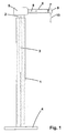
- In said drawing, figure -1- shows a side view of the crane, in its preferred embodiment with the horizontal telescopic arm.
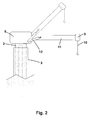
- Figure -2- shows a side view of the top part of the crane, in its alternative embodiment with the inclinable horizontal arm.
- Figure -3- shows a side view of the first phase of mounting the crane, in its preferred embodiment with the horizontal telescopic arm.
- Figure -4- shows a side view of the second phase of mounting the first section of the tower, in its preferred embodiment with the horizontal telescopic arm.
- Figure -5- shows a side view of the third phase of elevation of the crane, in its preferred embodiment with the horizontal telescopic arm.
- Figure -6- shows a side view of the fourth phase of mounting the following section of the tower, in the second step, in its preferred embodiment with the telescopic horizontal arm.
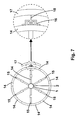
- Figure -7- shows a plan view of the fourth phase of mounting the following section of the tower, in the second step, with an enlarged detail of guiding between a roller and a guide rail
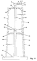
- Figure -8- shows a side view of the fourth phase of mounting the following section of the tower, in the third step, in its preferred embodiment with the telescopic horizontal arm.
- Figure -9- shows a side view of the fourth phase of mounting the following section of the tower, in the fifth step, in its preferred embodiment with the telescopic horizontal arm.
- Figure -10- shows a side view of the fourth phase of mounting the following section of the tower, in the seventh step, in its preferred embodiment with the telescopic horizontal arm.
- Figure -11- shows a side view upon completion of the fourth phase of mounting the following section of the tower, in its preferred embodiment with the telescopic horizontal arm.
- Figure -12- shows a side view of the fifth phase of hoisting the crane, in the first step, in its preferred embodiment with the horizontal telescopic arm.
- Figure -13- shows a side view of the fifth phase of hoisting the crane already completed, in its preferred embodiment with the horizontal telescopic arm.
- Figure -14- shows a side view of the sixth phase of dismantling the crane, showing the stage of elevating the auxiliary crane structure.
- Figure -15- shows a side view of the sixth phase of dismantling the crane, showing the auxiliary crane structure already mounted on the side of the tower, in the dual-arm embodiment, with the arms deployed.
- Figure -16- shows a side view of the sixth phase of dismantling the crane, showing the auxiliary crane structure already mounted on the side of the tower, in the horizontal arm embodiment.
- Figure -17- shows a side view of the sixth phase of dismantling the crane, showing the auxiliary crane structure already mounted on the side of the tower and with the self-climbing telescopic crane already dismantled and removed, at the stage of elevating the nacelle.
- Figure -18- shows a side view of the sixth phase of dismantling the crane, showing the auxiliary crane structure already mounted on the side of the tower and with the self-climbing telescopic crane already dismantled and removed, with the nacelle already mounted on the tower.
- Figure -19- shows a side view of the sixth phase of dismantling the crane, showing the auxiliary crane structure already mounted on the side of the tower and with the self-climbing telescopic crane already dismantled and removed, at the stage of elevating the blades.
- Figure - 20- shows a side view of the sixth phase of dismantling the crane, showing the auxiliary crane structure already mounted on the side of the tower and with the self-climbing telescopic crane already dismantled and removed, at the stage of elevating the blades.
- The self-climbing, telescopic crane for mounting pre-fabricated concrete towers that is the object of this invention, basically comprises, as can be seen in the attached drawing, an external vertical column (1), terminated at the bottom in a support (4), and an internal vertical column (2) that can move vertically via one or several actuators (3). The top part of the internal vertical column (2) terminates in a horizontally rotatable capstan (5) associated with a horizontal arm, terminating at the opposite end in a pulley (9) through which the hoist cable (10) moves.
- The horizontal arm associated with the capstan (5) preferably consists of an external tube (6) joined to the capstan (5) and an internal tube (7) with the pulley (9) at one end, said internal tube (7) moving horizontally in a telescopic manner in relation to the external tube (6) via one or several actuators (8). An alternative embodiment is envisaged in which the horizontal arm associated with the capstan (5) is formed by a tube (11) with the pulley (9) at one end, the inclination of the tube (11) being varied in relation to the capstan (5) via a rotation means, together with one or several actuators (12) thereby enabling the effective length of the arm to be varied.
- The height of the external vertical column (1) and the internal vertical column (2) shall be preferably slightly higher than the height of one section of the tower to be mounted.
- In all or in some of the mounting phases, it is envisaged the optional use of a work platform (19), that moves vertically and horizontally, associated with the external vertical column (1) via a collar (20) and mechanical elevating means (21), that allow the operators to perform the internal tasks of coupling, concreting, tensioning cables and sealing between the pre-fabricated concrete elements.
- This self-climbing telescopic crane involves a specific method of mounting a pre-fabricated concrete tower that comprises the following phases.
- a first phase of mounting the crane,
- a second phases of mounting the first section of the tower,
- a third phase of elevating the crane,
- a fourth phase of mounting the following section of the tower and
- a fifth phase of hoisting the crane,
- the third and fourth phases being repeated for each of the tower sections,
- and finishing with a sixth phase of dismantling the crane.
- The first phase of mounting the crane involves attaching the support (4) of the external vertical column (1) to the concrete footing (13) and subsequently assembling the rest of the elements that form the crane, in the minimum height position with the internal vertical column (2) fully inserted inside the external vertical column (1), with the aid of another small, conventional external crane.
- The second phase of mounting the first section of the tower comprises the adjacent stacking of the pre-fabricated concrete elements (14) supported at their top part by telescopic horizontal bracing members (15) on the top part of the external vertical column (1) in such a way that they form the tower section around the crane, with the crane remaining inside, at least one of the pre-fabricated concrete elements (14) having one or several guide rails (16) arranged vertically on its outer wall.
- The third phase of elevation of the crane comprises the telescopic extension of the internal vertical column (2) inside the external vertical column (1) by the effect of the actuators (3), until its maximum height is reached.
- The fourth phase of mounting the next section of the tower comprises:
- in a first step, the extending of the horizontal arm associated with the capstan (5) to its maximum extension,
- in a second step, the partial elevation of a pre-fabricated concrete element (17), guided at its bottom part, by one or several rollers (18) arranged on the inner bottom part and which slide along the guide rail or guide rails (16),
- in a third optional step, the support of the top part of the pre-fabricated concrete element (17) on the internal vertical column (2) by means of a bracing member (15) and a sliding collar (22),
- in a fourth step, the complete elevation of the pre-fabricated concrete element (17) over the pre-fabricated concrete element (14) of the bottom section, with the roller (18) exiting the guide rail or guide rails (16),
- in a fifth step of supporting the bottom part of the pre-fabricated concrete element (17) on the internal vertical column (2) by means of a bracing member (15) and a sliding collar (22),
- in a sixth step of rotating the pre-fabricated concrete element (17) by the rotation of the capstan (5) and of the horizontal arm until the pre-fabricated concrete element (17) is placed in its position,
- in a seventh step of the descent of the pre-fabricated concrete element (17) until it rests on the pre-fabricated concrete element (14) of the bottom section,
- the above steps being repeated until the section is completed, with at least one of the pre-fabricated concrete elements (17) having one or several guide rails (16) vertically arranged on its outer wall.
- The fifth phase of lifting the crane comprises a first step of removing the bracing members (15) and collar (22) located on the top part of the pre-fabricated concrete element (14) of the bottom section, and on the bottom part of the pre-fabricated concrete element (17) of the top section, as well as releasing the support (4) of the footing (13), a second step of the elevation of the external vertical column (1) via the actuators (3), keeping the internal vertical column (2) fixed at its top part by means of the rest of the bracing members (15) until the support (4) is at the height of the top part of the first section, a third step of placing a platform (23) at the top part of the lower segment of the tower and a fourth step of attaching the support (4) to the platform (23).
- The sixth phase of dismantling the crane comprises a stage of mounting an auxiliary crane structure (25) that temporarily uses the previously mounted tower as the crane tower, with a rotatable top part (26), on the outside of the last top segment of the tower, followed by a stage of releasing the support (4) of the footing (13), removing the bracing members (15) and remaining collars (22) and extracting the rest of the crane elements and platform (23) from the last segment of the tower via the auxiliary crane structure (25), followed by a stage of hoisting and mounting the nacelle (35) and the blades (36) by means of said auxiliary crane structure (25), finishing off with a stage of dismantling the auxiliary crane structure (25) and, optionally, the auxiliary elements that may remain such as guide rails (16), support plates (24), return pulley (37), etc...
- The stage of mounting the auxiliary crane structure (25) on the outside of the last top segment of the tower comprises a step in which the internal vertical column (2) extends telescopically through the inside of the external vertical column (1) due to the effect of the actuators (3), until it reaches its maximum height, followed by a step of extending the horizontal arm associated with the capstan (5) to its maximum extension. Following this there is a step of elevating the auxiliary crane structure (25), preferably of the lattice type, to reduce its weight, guided on its bottom part by one or several rollers (18), arranged on the inner bottom part and which slide along the guide rail or guide rails (16), followed by a step of attaching the auxiliary crane structure (25) to one or several support plates (24) that are inserted in the outer side of a pre-fabricated concrete element (17) of the top section, maintaining a separation distance with the tower. If a dual-arm crane structure is used, this stage finishes with a step of opening the two arms (26,27) of the auxiliary crane structure (25), previously folded by the rotation means (30) during the ascent, mounting of the dual capstan (31) near to the base of the tower and joined to the concrete footing (13), and laying the cables through the pulleys (29). In the alternative case of using a crane structure with horizontal arm, it finishes with a step of mounting the horizontal arm (32), the counterweights (33) and the movable capstan (34).
- The stage of hoisting and mounting the nacelle (35) and the blades (36) comprises a first step of elevating the nacelle (35), preferably in one piece, along the side of the tower
by means of the auxiliary crane structure (25), a second step of positioning over the top part of the tower and attachment to it, a third step of the lateral rotation of the nacelle (35) and of the auxiliary crane structure (25) to facilitate the following steps, followed by a step of elevation, also via the auxiliary crane structure (25), for each of the blades (36) and mounting on the nacelle (35). - Lastly, once all of the wind turbine elements have been mounted, the stage of dismantling the auxiliary crane structure (25) comprises a step of attaching a return pulley (37) at the top part of the tower, next to the auxiliary crane structure (25), a second step of folding the two arms (26,27) or the horizontal arm (32), a third step of attachment by means of a cable between the auxiliary crane structure (25) and the auxiliary capstan (38) that is in the nacelle (35), or the dual capstan (31), a fourth step of releasing the auxiliary crane structure (25) from the support plate or support plates (24) and concluding with a fifth step of the descent of the auxiliary crane structure (25), guided on its bottom part by one or several rollers (18) arranged on the inner bottom part and which slide along the guide rail or guide rails (16), to the ground.
- Alternatively, the sixth phase of dismantling the crane may consist solely of releasing the support (4) from the footing (13), removing the bracing members (15) and the remaining collars (22), and removing the rest of the crane elements and the platform (23) from the last segment of the tower using a conventional external crane, then placing them on the ground.
Claims (15)
- Self-climbing, telescopic crane for mounting pre-fabricated concrete towers characterized in that it comprises an external vertical column (1), terminated at the bottom in a support (4), and an internal vertical column (2) that can move vertically via one or several actuators (3). The top part of said internal vertical column (2) terminates in a horizontally rotatable capstan (5) associated with a horizontal arm, terminating at the opposite end in a pulley (9) through which the hoist cable (10) moves.
- Self-climbing, telescopic crane for mounting pre-fabricated concrete towers, according to claim 1, wherein the horizontal arm associated with the capstan (5) is formed by an external tube (6) joined to the capstan (5) and an internal tube (7) with the pulley (9) at one end, said internal tube (7) being able to move horizontally in relation to the external tube (6) via one or several actuators (8).
- Self-climbing, telescopic crane for mounting pre-fabricated concrete towers, according to claim 1, wherein the horizontal arm associated with the capstan (5) is formed by a tube (11) with the pulley (9) at one end, the inclination of the tube (11) being variable, via a rotation means, in relation to the capstan (5) together with one or several actuators (12).
- Self-climbing, telescopic crane for mounting pre-fabricated concrete towers, according to claim 1, wherein it includes a work platform (19) that moves vertically and horizontally, associated with the external vertical column (1) via a collar (20) and mechanical elevating means (21).
- Method for mounting a pre-fabricated concrete tower by means of a self-climbing, telescopic crane such as that described in the preceding claims, characterized in that it comprises a first phase of mounting the crane, a second phase of mounting the first section of the tower, a third phase of elevating the crane, a fourth phase of mounting the following section of the tower, a fifth phase of lifting the crane, the third and fourth phases being repeated for each of the tower sections, and finishing with a sixth phase of dismantling the crane.
- Method for mounting a pre-fabricated concrete tower, according to claim 5, wherein the first phase of mounting the crane entails attaching the support (4) of the external vertical column (1) to the concrete footing (13) and subsequently assembling the rest of the elements that form the crane, in the minimum height position with the internal vertical column (2) fully inserted inside the external vertical column (1), with the aid of another small, conventional external crane.
- Method for mounting a pre-fabricated concrete tower, according to claim 5, wherein the second phase of mounting the first section of the tower comprises the adjacent stacking of the pre-fabricated concrete elements (14) supported at their top part by telescopic horizontal bracing members (15) on the top part of the external vertical column (1) in such a way that they form the tower section around the crane and the crane remains inside, at least one of the pre-fabricated concrete elements (14) having one or several guide rails (16) arranged vertically on its outer wall.
- Method for mounting a pre-fabricated concrete tower, according to claim 5, wherein the third phase of elevation of the crane comprises the telescopic extending of the internal vertical column (2) inside the external vertical column (1) by the effect of the actuators (3), until its maximum height is reached.
- Method for mounting a pre-fabricated concrete tower, according to claim 5, wherein the fourth phase of mounting the following section of the tower comprises, in a first step, the extending of the horizontal arm associated with the capstan (5) to its maximum extension, in a second step, the partial elevation of a pre-fabricated concrete element (17) guided at its bottom part by one or several rollers (18) arranged on the inner bottom part and which slide along the guide rail or guide rails (16), in a third optional step of supporting the top part of the pre-fabricated concrete element (17) on the internal vertical column (2) by means of a bracing member (15) and a sliding collar (22), in a fourth step of fully elevating the pre-fabricated concrete element (17) over the pre-fabricated concrete element (14) of the bottom section, the roller (18) exiting the guide rail or guide rails (16), in a fifth step of supporting the bottom part of the pre-fabricated concrete element (17) on the internal vertical column (2) by means of a bracing member (15) and a sliding collar (22), in a sixth step of rotating the pre-fabricated concrete element (17) by the rotation of the capstan (5) and of the horizontal arm until the pre-fabricated concrete element (17) is placed in its position, in a seventh step of the descent of the pre-fabricated concrete element (17) until it rests on the pre-fabricated concrete element (14) of the bottom section, the previous steps being repeated until the section is completed, also at least one of the pre-fabricated concrete elements (17) having one or several guide rails (16) vertically arranged on its outer wall.
- Method for mounting a pre-fabricated concrete tower, according to claim 5, wherein the fifth phase of lifting the crane comprises a first step of removing the bracing members (15) and collar (22) located on the top part of the pre-fabricated concrete element (14) of the lower section, and on the bottom part of the pre-fabricated concrete element (17) of the upper section, as well as releasing the support (4) of the footing (13), a second step of elevating the external vertical column (1) via the actuators (3), keeping the internal vertical column (2) fixed at its top part by means of the rest of the bracing members (15) until the support (4) is at the height of the top part of the first section, a third step of placing a platform (23) at the top part of the lower segment of the tower and a fourth step of attaching the support (4) to the platform (23).
- Method for mounting a pre-fabricated concrete tower, according to claim 5, wherein the sixth phase of dismantling the crane entails releasing the support (4) from the footing (13), removing the bracing members (15) and the remaining collars (22), and removing the rest of the crane elements and the platform (23) from the last segment of the tower using a conventional external crane and then placing them on the ground.
- Method for mounting a pre-fabricated concrete tower, according to claim 5, wherein the sixth phase of dismantling the crane comprises a stage of mounting an auxiliary crane structure (25) with a rotatable top part (26), on the outside of the last upper segment of the tower, followed by a stage of releasing the support (4) of the footing (13), removing the bracing members (15) and remaining collars (22) and removing the rest of the crane elements and platform (23) from the last segment of the tower via the auxiliary crane structure (25), followed by a stage of hoisting and mounting the nacelle (35) and the blades (36) by means of said auxiliary crane structure (25), finishing off with a stage of dismantling the auxiliary crane structure (25).
- Method for mounting a pre-fabricated concrete tower, according to claim 12, wherein the stage of mounting an auxiliary crane structure (25) on the outside of the last upper segment of the tower comprises a step of the telescopic extending of the internal vertical column (2) inside the external vertical column (1) by the effect of the actuators (3), until its maximum height is reached, followed by a step of extending the horizontal arm associated with the capstan (5) to its maximum extension, continuing with a step of elevating the auxiliary crane structure (25) guided at its bottom part by one or several rollers (18) arranged on the inner bottom part and which slide along the guide rail or guide rails (16), followed by a step of attaching the auxiliary crane structure (25) to one or several support plates (24) that are inserted in the outer side of a pre-fabricated concrete element (17) of the top section, maintaining a separation distance with the tower, finishing, in the case of a dual-arm crane structure, with a step of opening the two arms (26,27) of the auxiliary crane structure (25), previously folded by the rotation means (30), during the ascent, the mounting of the dual capstan (31) near to the base of the tower and joined to the concrete footing (13), and the laying of the cables through the pulleys (29), or, in the case of a crane structure with horizontal arm, with a step of mounting the horizontal arm (32), the counterweights (33) and the movable capstan (34).
- Method for mounting a pre-fabricated concrete tower, according to claim 12, wherein the stage of hoisting and mounting the nacelle (35) and the blades (36) comprises a first step of elevating the nacelle (35) up the side of the tower, by means of the auxiliary crane structure (25), a second step of positioning at the top part of the tower and attachment to it, a third step of the lateral rotation of the nacelle (35) and of the auxiliary crane structure (25) to facilitate the next steps, followed by a step of elevating, also via the auxiliary crane structure (25), each of the blades (36) and mounting on the nacelle (35).
- Method for mounting a pre-fabricated concrete tower, according to claim 12, wherein the stage of dismantling the auxiliary crane structure (25) comprises a step of attaching a return pulley (37) at the top part of the tower, next to the auxiliary crane structure (25), a second step of folding the two arms (26,27) or the horizontal arm (32), a third step of attachment by means of a cable between the auxiliary crane structure (25) and the auxiliary capstan (38) in the nacelle (35), or the dual capstan (31), a fourth step of releasing the auxiliary crane structure (25) from the support plate or support plates (24) and concluding with a fifth step of the descent of the auxiliary crane structure (25), guided at its bottom part by one or several rollers (18) arranged on the inner bottom part and which slide along the guide rail or guide rails (16), to the ground.
Applications Claiming Priority (2)
| Application Number | Priority Date | Filing Date | Title |
|---|---|---|---|
| ES201230754A ES2435211B2 (en) | 2012-05-18 | 2012-05-18 | Self-climbing telescopic crane and assembly procedure for precast concrete towers |
| PCT/ES2013/070316 WO2013171359A1 (en) | 2012-05-18 | 2013-05-17 | Self-climbing telescopic crane and method for mounting pre-fabricated concrete towers |
Publications (3)
| Publication Number | Publication Date |
|---|---|
| EP2851328A1 true EP2851328A1 (en) | 2015-03-25 |
| EP2851328A4 EP2851328A4 (en) | 2016-01-20 |
| EP2851328B1 EP2851328B1 (en) | 2018-04-18 |
Family
ID=49583193
Family Applications (1)
| Application Number | Title | Priority Date | Filing Date |
|---|---|---|---|
| EP13791193.9A Active EP2851328B1 (en) | 2012-05-18 | 2013-05-17 | Self-climbing telescopic crane and method for mounting pre-fabricated concrete towers |
Country Status (13)
| Country | Link |
|---|---|
| US (1) | US20150167342A1 (en) |
| EP (1) | EP2851328B1 (en) |
| CN (1) | CN104428237A (en) |
| AU (1) | AU2013261673B2 (en) |
| BR (1) | BR112014028556A2 (en) |
| CA (1) | CA2873821C (en) |
| CL (1) | CL2014003128A1 (en) |
| ES (2) | ES2435211B2 (en) |
| IN (1) | IN2014MN02329A (en) |
| MA (1) | MA37608B1 (en) |
| MX (1) | MX2014014014A (en) |
| WO (1) | WO2013171359A1 (en) |
| ZA (1) | ZA201408199B (en) |
Cited By (6)
| Publication number | Priority date | Publication date | Assignee | Title |
|---|---|---|---|---|
| EP3163069A1 (en) * | 2015-10-30 | 2017-05-03 | Acciona Windpower S.a. | Wind turbine assembly system and associated method |
| EP3208405A1 (en) | 2016-02-18 | 2017-08-23 | Technische Hochschule Mittelhessen | Device and method for assembling tower-like structures from pre-fabricated elements |
| CN107697818A (en) * | 2017-10-17 | 2018-02-16 | 郑州科润机电工程有限公司 | A kind of prestressed concrete wind-power tower wall construction method and special construction apparatus |
| EP3372744A1 (en) * | 2017-03-07 | 2018-09-12 | KB Vorspann-Technik GmbH | Cable guide for guiding a rope without damage and corresponding method |
| DE102017204566A1 (en) * | 2017-03-20 | 2018-09-20 | KB Vorspann-Technik GmbH | Rope guide for the damage-free guiding of a rope as well as appropriate procedure |
| WO2019170728A1 (en) * | 2018-03-07 | 2019-09-12 | Max Bögl Wind AG | Method for introducing prestressed elements into a tower, assembly device, unwinding device and adapter device |
Families Citing this family (24)
| Publication number | Priority date | Publication date | Assignee | Title |
|---|---|---|---|---|
| WO2014082176A1 (en) * | 2012-11-27 | 2014-06-05 | Marmen Inc. | Lifting system for wind turbine towers and method for erecting a wind turbine tower |
| US9434582B2 (en) * | 2012-12-05 | 2016-09-06 | Brady Paul Arthur | Dual crane apparatus and method of use |
| DE102013011180B4 (en) * | 2013-07-04 | 2020-09-10 | Liebherr-Werk Ehingen Gmbh | Collar storage for a telescopic boom as well as telescopic boom and crane |
| US9394880B2 (en) * | 2014-07-11 | 2016-07-19 | Michael Zuteck | Tall wind turbine tower erection with climbing crane |
| CN106662076A (en) * | 2014-07-11 | 2017-05-10 | 迈克尔·D·朱泰克 | Tall wind turbine tower erection with climbing crane |
| US9657495B2 (en) * | 2015-10-14 | 2017-05-23 | James D. Lockwood | Crane system incorporated into a tower |
| DE102016002372A1 (en) * | 2016-02-19 | 2017-08-24 | Senvion Gmbh | Method for assembling a tubular tower segment |
| ES2665004B1 (en) * | 2016-10-24 | 2019-01-29 | Gamesa Innovation & Technology S L | Crane of a wind turbine |
| EP3379078A1 (en) * | 2017-03-23 | 2018-09-26 | Nordex Energy GmbH | Method and device for mounting a tower for a wind turbine and the tower of a wind turbine |
| ES2695626B2 (en) | 2017-06-30 | 2020-05-19 | Hws Concrete Towers S L | Self-climbing device for vertical and quasi-vertical concrete surfaces and operating procedure. |
| WO2019116511A1 (en) * | 2017-12-14 | 2019-06-20 | ベステラ株式会社 | Method of dismantling tower-type wind power generation facility |
| ES2738179A1 (en) * | 2018-07-18 | 2020-01-20 | Leunamme Eng S L | DEVICE FOR ASSEMBLING AEROGENERATOR COMPONENTS AND ASSEMBLY PROCEDURE WITH SUCH DEVICE (Machine-translation by Google Translate, not legally binding) |
| EP3632833A1 (en) * | 2018-10-02 | 2020-04-08 | S&L Access Systems AB | A lifting assembly for a wind turbine |
| US10669994B1 (en) * | 2019-01-28 | 2020-06-02 | Joseph R. Kucic | Multi-column wind turbine tower and erection method |
| KR101999500B1 (en) * | 2019-02-07 | 2019-07-11 | 채봉철 | Equipment for installing and dismantling of wind turbine and construction methods with it |
| JP7245098B2 (en) * | 2019-03-28 | 2023-03-23 | 株式会社シーテック | Relocation method of mast guide device for tower assembly work |
| US20230068808A1 (en) * | 2020-02-17 | 2023-03-02 | Vestas Wind Systems A/S | A nacelle for a wind turbine and a method of making a wind turbine |
| CN112030767A (en) * | 2020-09-04 | 2020-12-04 | 中交路桥华南工程有限公司 | Steel tower unilateral climbing type lifting formwork and application to inclined single-column steel cable tower |
| CN112696320A (en) * | 2020-10-14 | 2021-04-23 | 向阳 | Safety and stability wind power generation set |
| CN113338697A (en) * | 2021-06-24 | 2021-09-03 | 国网辽宁省电力有限公司辽阳供电公司 | Tool for hoisting main materials of decomposition and assembly iron tower and installation method |
| CN113586350A (en) * | 2021-08-05 | 2021-11-02 | 华能赫章风力发电有限公司 | Mounting rack for wind driven generator |
| EP4140932A1 (en) * | 2021-08-30 | 2023-03-01 | Siemens Gamesa Renewable Energy Innovation & Technology S.L. | Climbing crane for erecting a wind turbine and method for erecting a wind turbine with a climbing crane |
| CN116464607B (en) * | 2023-05-29 | 2024-02-02 | 河南金利重工科技有限公司 | Lifting construction method and structure of wind power generation equipment |
| CN117049408B (en) * | 2023-10-11 | 2023-12-26 | 上海戈洛立科技有限公司 | Tower crane system for wind generating set |
Family Cites Families (27)
| Publication number | Priority date | Publication date | Assignee | Title |
|---|---|---|---|---|
| FR1062850A (en) * | 1951-09-25 | 1954-04-27 | Device allowing the distance so to be carried at any height? hook tower cranes | |
| FR1119282A (en) * | 1955-01-11 | 1956-06-18 | Chantiers & Ateliers De Constr | Crane |
| FR1203098A (en) * | 1958-07-11 | 1960-01-15 | Potain & Cie Ets F | Improvements to crane devices for building construction |
| US3938670A (en) * | 1969-04-09 | 1976-02-17 | General Crane Industries Limited | Tower crane |
| FR2091878B1 (en) * | 1970-03-19 | 1976-10-29 | Noly Jean | |
| US4498556A (en) * | 1982-09-11 | 1985-02-12 | Access Engineering Ltd. | Vertically movable, road towable work platform |
| AU651616B2 (en) * | 1990-10-08 | 1994-07-28 | Kajima Corporation | Process for constructing frame and erection |
| JP2597947B2 (en) * | 1993-05-28 | 1997-04-09 | 守夫 反町 | Scaffolding equipment |
| US6226955B1 (en) * | 1998-12-28 | 2001-05-08 | Jerry L. Lorrigan | Method and apparatus for handling building materials and implements |
| SE513400C2 (en) * | 1999-01-15 | 2000-09-11 | Aake Toernqvist | Method of arranging a stand for at least one person in a substantially empty cistern, as well as a stand |
| ES2234392B1 (en) | 2003-03-31 | 2006-10-16 | Manuel Torres Martinez | PROCESS FOR THE ASSEMBLY OF THE TOWER OF AN AEROGENERATOR AND TOWER BUILT ASI. |
| ES1058539Y (en) | 2004-10-11 | 2005-04-01 | Inneo21 S L | PERFECTED MODULAR TOWER STRUCTURE FOR WIND TURBINES AND OTHER APPLICATIONS. |
| ES2246734B1 (en) | 2005-04-21 | 2007-04-16 | STRUCTURAL CONCRETE & STEEL, S.L. | PREFABRICATED MODULAR TOWER. |
| FR2903739B1 (en) * | 2006-07-12 | 2009-04-10 | Eole Overseas Company Ltd | "DEVICE AND METHOD FOR RAPID DISASSEMBLY OF A ROTOR AND A BOAT NACELLE FROM A WINDMILL, AND A WIND TURBINE PROVIDED WITH SUCH A DEVICE" |
| ES2326010B2 (en) | 2006-08-16 | 2011-02-18 | Inneo21, S.L. | STRUCTURE AND PROCEDURE FOR ASSEMBLING CONCRETE TOWERS FOR WIND TURBINES. |
| ES2296531B1 (en) | 2006-09-13 | 2009-03-01 | GAMESA INNOVATION & TECHNOLOGY, S.L. | TOWER FOR AEROGENERATORS ASSEMBLED WITH PREFABRICATED ELEMENTS. |
| NL1032591C2 (en) * | 2006-09-28 | 2008-03-31 | Mecal Applied Mechanics B V | Crane and method. |
| WO2009056898A1 (en) * | 2007-11-02 | 2009-05-07 | Alejandro Cortina-Cordero | Post-tensioned concrete tower for wind turbines |
| EP2340369A2 (en) * | 2008-10-31 | 2011-07-06 | Vestas Wind Systems A/S | Method of erecting a tower |
| CN101737273A (en) * | 2008-11-17 | 2010-06-16 | 维斯塔斯风力系统集团公司 | A tower, a wind turbine and a method for arranging a platform inside a tower |
| US8555600B2 (en) * | 2008-12-10 | 2013-10-15 | Cortina Innovations, S.A. De C.V. | Method for mounting in sections an annular tower for wind power generator, heliostatic power generator or chimney composed from three concrete segments or more |
| US20100281818A1 (en) * | 2009-05-07 | 2010-11-11 | Southworth George L | Method for building wind turbine tower |
| CN101590982A (en) * | 2009-06-24 | 2009-12-02 | 张世宇 | Wind power generation climbing hoisting crane |
| WO2011032559A2 (en) * | 2009-09-15 | 2011-03-24 | Ib Andresen Industri A/S | Tubular building structure with hingedly connected platform segment |
| US8443571B2 (en) * | 2009-09-19 | 2013-05-21 | Btpatent Llc | Wind power equipment and assembly |
| WO2011082710A1 (en) * | 2010-01-07 | 2011-07-14 | Vestas Wind Systems A/S | Method of lifting a wind turbine component toward a top portion of a wind turbine tower |
| DK2374966T3 (en) * | 2010-04-06 | 2016-11-07 | Soletanche Freyssinet | A method of building a hybrid tower for a wind turbine |
-
2012
- 2012-05-18 ES ES201230754A patent/ES2435211B2/en not_active Expired - Fee Related
-
2013
- 2013-05-17 WO PCT/ES2013/070316 patent/WO2013171359A1/en active Application Filing
- 2013-05-17 US US14/401,788 patent/US20150167342A1/en not_active Abandoned
- 2013-05-17 CN CN201380034202.1A patent/CN104428237A/en active Pending
- 2013-05-17 BR BR112014028556A patent/BR112014028556A2/en not_active Application Discontinuation
- 2013-05-17 MX MX2014014014A patent/MX2014014014A/en unknown
- 2013-05-17 AU AU2013261673A patent/AU2013261673B2/en not_active Ceased
- 2013-05-17 CA CA2873821A patent/CA2873821C/en active Active
- 2013-05-17 EP EP13791193.9A patent/EP2851328B1/en active Active
- 2013-05-17 ES ES13791193.9T patent/ES2675344T3/en active Active
-
2014
- 2014-11-10 ZA ZA2014/08199A patent/ZA201408199B/en unknown
- 2014-11-17 IN IN2329MUN2014 patent/IN2014MN02329A/en unknown
- 2014-11-18 CL CL2014003128A patent/CL2014003128A1/en unknown
- 2014-12-04 MA MA37608A patent/MA37608B1/en unknown
Cited By (10)
| Publication number | Priority date | Publication date | Assignee | Title |
|---|---|---|---|---|
| EP3163069A1 (en) * | 2015-10-30 | 2017-05-03 | Acciona Windpower S.a. | Wind turbine assembly system and associated method |
| US10815687B2 (en) | 2015-10-30 | 2020-10-27 | Acciona Windpower, S.A. | Wind turbine assembly system and associated method |
| EP3208405A1 (en) | 2016-02-18 | 2017-08-23 | Technische Hochschule Mittelhessen | Device and method for assembling tower-like structures from pre-fabricated elements |
| EP3372744A1 (en) * | 2017-03-07 | 2018-09-12 | KB Vorspann-Technik GmbH | Cable guide for guiding a rope without damage and corresponding method |
| DE102017204566A1 (en) * | 2017-03-20 | 2018-09-20 | KB Vorspann-Technik GmbH | Rope guide for the damage-free guiding of a rope as well as appropriate procedure |
| CN107697818A (en) * | 2017-10-17 | 2018-02-16 | 郑州科润机电工程有限公司 | A kind of prestressed concrete wind-power tower wall construction method and special construction apparatus |
| CN107697818B (en) * | 2017-10-17 | 2023-10-17 | 郑州科润机电工程有限公司 | Construction method and special construction equipment for wall of prestressed concrete wind power tower |
| WO2019170728A1 (en) * | 2018-03-07 | 2019-09-12 | Max Bögl Wind AG | Method for introducing prestressed elements into a tower, assembly device, unwinding device and adapter device |
| CN111868344A (en) * | 2018-03-07 | 2020-10-30 | 马克斯·博格风能股份公司 | Method for introducing a prestressing element into a tower, mounting device, unwinding device and adapter device |
| US20210040762A1 (en) * | 2018-03-07 | 2021-02-11 | Max Bögl Wind AG | Method for Introducing Prestressed Elements into a Tower, Assembly Device, Unwinding Device and Adapter Device |
Also Published As
| Publication number | Publication date |
|---|---|
| ZA201408199B (en) | 2017-04-26 |
| CA2873821A1 (en) | 2013-11-21 |
| US20150167342A1 (en) | 2015-06-18 |
| AU2013261673A1 (en) | 2014-12-11 |
| IN2014MN02329A (en) | 2015-08-14 |
| MA37608B1 (en) | 2016-11-30 |
| ES2675344T3 (en) | 2018-07-10 |
| BR112014028556A2 (en) | 2018-04-24 |
| ES2435211B2 (en) | 2014-12-12 |
| AU2013261673B2 (en) | 2017-10-12 |
| CN104428237A (en) | 2015-03-18 |
| EP2851328A4 (en) | 2016-01-20 |
| CL2014003128A1 (en) | 2015-08-07 |
| EP2851328B1 (en) | 2018-04-18 |
| WO2013171359A1 (en) | 2013-11-21 |
| MA37608A1 (en) | 2016-04-29 |
| MX2014014014A (en) | 2015-07-06 |
| CA2873821C (en) | 2020-07-14 |
| ES2435211A1 (en) | 2013-12-16 |
Similar Documents
| Publication | Publication Date | Title |
|---|---|---|
| EP2851328B1 (en) | Self-climbing telescopic crane and method for mounting pre-fabricated concrete towers | |
| EP2746571B1 (en) | Wind turbine assembly system | |
| EP2374966A1 (en) | Method of building a hybrid tower for a wind generator | |
| DK2715113T3 (en) | METHOD FOR SETTING UP, MAINTAINING AND DISASSEMBLING A WIND TURBINE | |
| US8584429B2 (en) | Tower erection system and method | |
| US10815687B2 (en) | Wind turbine assembly system and associated method | |
| CN110944928B (en) | Lifting assembly for lifting a component to a wind turbine and method of using the same | |
| EP3301064B1 (en) | Apparatus for lifting heavy loads and method for assembling or disassembling an apparatus for lifting heavy loads | |
| EP3379079B1 (en) | Device for assembly and maintenance of a tower for a wind turbine and use of the same | |
| EP3164557B1 (en) | Support tower, particularly for a wind turbine | |
| CN112041522B (en) | Movable module for hoisting telescopic high tower and method for hoisting telescopic high tower | |
| EP1677001A2 (en) | System for removing the cover roof from a wind turbine | |
| CN207647152U (en) | Tower lifts constructing device certainly | |
| EP3326959A1 (en) | Lifting arrangement for a mast, a mast divided into elements, and methods for assembling, dismantling and servicing of a mast | |
| RU2795818C2 (en) | Heavy load lift device | |
| US20220177281A1 (en) | Apparatus for Lifting Heavy Loads | |
| CN110914188B (en) | Crane, method for assembling crane and method for disassembling crane | |
| WO2021121492A1 (en) | A method for installing or removing wind turbine components |
Legal Events
| Date | Code | Title | Description |
|---|---|---|---|
| PUAI | Public reference made under article 153(3) epc to a published international application that has entered the european phase |
Free format text: ORIGINAL CODE: 0009012 |
|
| 17P | Request for examination filed |
Effective date: 20141210 |
|
| AK | Designated contracting states |
Kind code of ref document: A1 Designated state(s): AL AT BE BG CH CY CZ DE DK EE ES FI FR GB GR HR HU IE IS IT LI LT LU LV MC MK MT NL NO PL PT RO RS SE SI SK SM TR |
|
| AX | Request for extension of the european patent |
Extension state: BA ME |
|
| DAX | Request for extension of the european patent (deleted) | ||
| REG | Reference to a national code |
Ref country code: DE Ref legal event code: R079 Ref document number: 602013036151 Country of ref document: DE Free format text: PREVIOUS MAIN CLASS: B66C0023180000 Ipc: B66C0023320000 |
|
| RA4 | Supplementary search report drawn up and despatched (corrected) |
Effective date: 20151218 |
|
| RIC1 | Information provided on ipc code assigned before grant |
Ipc: B66C 23/32 20060101AFI20151214BHEP Ipc: B66C 23/20 20060101ALI20151214BHEP Ipc: F03D 1/00 20060101ALI20151214BHEP |
|
| 17Q | First examination report despatched |
Effective date: 20170103 |
|
| GRAP | Despatch of communication of intention to grant a patent |
Free format text: ORIGINAL CODE: EPIDOSNIGR1 |
|
| INTG | Intention to grant announced |
Effective date: 20170925 |
|
| GRAS | Grant fee paid |
Free format text: ORIGINAL CODE: EPIDOSNIGR3 |
|
| GRAA | (expected) grant |
Free format text: ORIGINAL CODE: 0009210 |
|
| AK | Designated contracting states |
Kind code of ref document: B1 Designated state(s): AL AT BE BG CH CY CZ DE DK EE ES FI FR GB GR HR HU IE IS IT LI LT LU LV MC MK MT NL NO PL PT RO RS SE SI SK SM TR |
|
| REG | Reference to a national code |
Ref country code: GB Ref legal event code: FG4D |
|
| REG | Reference to a national code |
Ref country code: CH Ref legal event code: EP |
|
| REG | Reference to a national code |
Ref country code: AT Ref legal event code: REF Ref document number: 990222 Country of ref document: AT Kind code of ref document: T Effective date: 20180515 |
|
| REG | Reference to a national code |
Ref country code: IE Ref legal event code: FG4D |
|
| REG | Reference to a national code |
Ref country code: DE Ref legal event code: R096 Ref document number: 602013036151 Country of ref document: DE |
|
| REG | Reference to a national code |
Ref country code: FR Ref legal event code: PLFP Year of fee payment: 6 |
|
| REG | Reference to a national code |
Ref country code: ES Ref legal event code: FG2A Ref document number: 2675344 Country of ref document: ES Kind code of ref document: T3 Effective date: 20180710 |
|
| REG | Reference to a national code |
Ref country code: NL Ref legal event code: MP Effective date: 20180418 |
|
| REG | Reference to a national code |
Ref country code: LT Ref legal event code: MG4D |
|
| PG25 | Lapsed in a contracting state [announced via postgrant information from national office to epo] |
Ref country code: NL Free format text: LAPSE BECAUSE OF FAILURE TO SUBMIT A TRANSLATION OF THE DESCRIPTION OR TO PAY THE FEE WITHIN THE PRESCRIBED TIME-LIMIT Effective date: 20180418 |
|
| PG25 | Lapsed in a contracting state [announced via postgrant information from national office to epo] |
Ref country code: SE Free format text: LAPSE BECAUSE OF FAILURE TO SUBMIT A TRANSLATION OF THE DESCRIPTION OR TO PAY THE FEE WITHIN THE PRESCRIBED TIME-LIMIT Effective date: 20180418 Ref country code: AL Free format text: LAPSE BECAUSE OF FAILURE TO SUBMIT A TRANSLATION OF THE DESCRIPTION OR TO PAY THE FEE WITHIN THE PRESCRIBED TIME-LIMIT Effective date: 20180418 Ref country code: FI Free format text: LAPSE BECAUSE OF FAILURE TO SUBMIT A TRANSLATION OF THE DESCRIPTION OR TO PAY THE FEE WITHIN THE PRESCRIBED TIME-LIMIT Effective date: 20180418 Ref country code: NO Free format text: LAPSE BECAUSE OF FAILURE TO SUBMIT A TRANSLATION OF THE DESCRIPTION OR TO PAY THE FEE WITHIN THE PRESCRIBED TIME-LIMIT Effective date: 20180718 Ref country code: BG Free format text: LAPSE BECAUSE OF FAILURE TO SUBMIT A TRANSLATION OF THE DESCRIPTION OR TO PAY THE FEE WITHIN THE PRESCRIBED TIME-LIMIT Effective date: 20180718 Ref country code: LT Free format text: LAPSE BECAUSE OF FAILURE TO SUBMIT A TRANSLATION OF THE DESCRIPTION OR TO PAY THE FEE WITHIN THE PRESCRIBED TIME-LIMIT Effective date: 20180418 Ref country code: PL Free format text: LAPSE BECAUSE OF FAILURE TO SUBMIT A TRANSLATION OF THE DESCRIPTION OR TO PAY THE FEE WITHIN THE PRESCRIBED TIME-LIMIT Effective date: 20180418 |
|
| REG | Reference to a national code |
Ref country code: ES Ref legal event code: PC2A Owner name: STRUCTURAL CONCRETE & STEEL, S.L. Effective date: 20181121 |
|
| PG25 | Lapsed in a contracting state [announced via postgrant information from national office to epo] |
Ref country code: GR Free format text: LAPSE BECAUSE OF FAILURE TO SUBMIT A TRANSLATION OF THE DESCRIPTION OR TO PAY THE FEE WITHIN THE PRESCRIBED TIME-LIMIT Effective date: 20180719 Ref country code: LV Free format text: LAPSE BECAUSE OF FAILURE TO SUBMIT A TRANSLATION OF THE DESCRIPTION OR TO PAY THE FEE WITHIN THE PRESCRIBED TIME-LIMIT Effective date: 20180418 Ref country code: HR Free format text: LAPSE BECAUSE OF FAILURE TO SUBMIT A TRANSLATION OF THE DESCRIPTION OR TO PAY THE FEE WITHIN THE PRESCRIBED TIME-LIMIT Effective date: 20180418 Ref country code: RS Free format text: LAPSE BECAUSE OF FAILURE TO SUBMIT A TRANSLATION OF THE DESCRIPTION OR TO PAY THE FEE WITHIN THE PRESCRIBED TIME-LIMIT Effective date: 20180418 |
|
| REG | Reference to a national code |
Ref country code: GB Ref legal event code: 732E Free format text: REGISTERED BETWEEN 20181115 AND 20181130 |
|
| REG | Reference to a national code |
Ref country code: ES Ref legal event code: PC2A Owner name: HWS CONCRETE TOWERS, S.L. Effective date: 20181207 |
|
| REG | Reference to a national code |
Ref country code: CH Ref legal event code: PL |
|
| REG | Reference to a national code |
Ref country code: AT Ref legal event code: MK05 Ref document number: 990222 Country of ref document: AT Kind code of ref document: T Effective date: 20180418 |
|
| REG | Reference to a national code |
Ref country code: DE Ref legal event code: R082 Ref document number: 602013036151 Country of ref document: DE Representative=s name: SCHAEFER, MATTHIAS W., DIPL.-ING., DE Ref country code: DE Ref legal event code: R081 Ref document number: 602013036151 Country of ref document: DE Owner name: HWS CONCRETE TOWERS, S.L., ES Free format text: FORMER OWNER: STRUCTURAL RESEARCH S.L., HUESCA, ES Ref country code: DE Ref legal event code: R081 Ref document number: 602013036151 Country of ref document: DE Owner name: HWS CONCRETE TOWERS, S.L., ES Free format text: FORMER OWNER: STRUCTURAL CONCRETE & STEEL, S.L., HUESCA, ES |
|
| PG25 | Lapsed in a contracting state [announced via postgrant information from national office to epo] |
Ref country code: PT Free format text: LAPSE BECAUSE OF FAILURE TO SUBMIT A TRANSLATION OF THE DESCRIPTION OR TO PAY THE FEE WITHIN THE PRESCRIBED TIME-LIMIT Effective date: 20180820 |
|
| REG | Reference to a national code |
Ref country code: GB Ref legal event code: 732E Free format text: REGISTERED BETWEEN 20181206 AND 20181212 |
|
| REG | Reference to a national code |
Ref country code: DE Ref legal event code: R097 Ref document number: 602013036151 Country of ref document: DE |
|
| REG | Reference to a national code |
Ref country code: BE Ref legal event code: MM Effective date: 20180531 |
|
| PG25 | Lapsed in a contracting state [announced via postgrant information from national office to epo] |
Ref country code: RO Free format text: LAPSE BECAUSE OF FAILURE TO SUBMIT A TRANSLATION OF THE DESCRIPTION OR TO PAY THE FEE WITHIN THE PRESCRIBED TIME-LIMIT Effective date: 20180418 Ref country code: AT Free format text: LAPSE BECAUSE OF FAILURE TO SUBMIT A TRANSLATION OF THE DESCRIPTION OR TO PAY THE FEE WITHIN THE PRESCRIBED TIME-LIMIT Effective date: 20180418 Ref country code: CZ Free format text: LAPSE BECAUSE OF FAILURE TO SUBMIT A TRANSLATION OF THE DESCRIPTION OR TO PAY THE FEE WITHIN THE PRESCRIBED TIME-LIMIT Effective date: 20180418 Ref country code: EE Free format text: LAPSE BECAUSE OF FAILURE TO SUBMIT A TRANSLATION OF THE DESCRIPTION OR TO PAY THE FEE WITHIN THE PRESCRIBED TIME-LIMIT Effective date: 20180418 Ref country code: DK Free format text: LAPSE BECAUSE OF FAILURE TO SUBMIT A TRANSLATION OF THE DESCRIPTION OR TO PAY THE FEE WITHIN THE PRESCRIBED TIME-LIMIT Effective date: 20180418 Ref country code: SK Free format text: LAPSE BECAUSE OF FAILURE TO SUBMIT A TRANSLATION OF THE DESCRIPTION OR TO PAY THE FEE WITHIN THE PRESCRIBED TIME-LIMIT Effective date: 20180418 Ref country code: MC Free format text: LAPSE BECAUSE OF FAILURE TO SUBMIT A TRANSLATION OF THE DESCRIPTION OR TO PAY THE FEE WITHIN THE PRESCRIBED TIME-LIMIT Effective date: 20180418 |
|
| REG | Reference to a national code |
Ref country code: IE Ref legal event code: MM4A |
|
| PLBE | No opposition filed within time limit |
Free format text: ORIGINAL CODE: 0009261 |
|
| STAA | Information on the status of an ep patent application or granted ep patent |
Free format text: STATUS: NO OPPOSITION FILED WITHIN TIME LIMIT |
|
| PG25 | Lapsed in a contracting state [announced via postgrant information from national office to epo] |
Ref country code: SM Free format text: LAPSE BECAUSE OF FAILURE TO SUBMIT A TRANSLATION OF THE DESCRIPTION OR TO PAY THE FEE WITHIN THE PRESCRIBED TIME-LIMIT Effective date: 20180418 Ref country code: IT Free format text: LAPSE BECAUSE OF FAILURE TO SUBMIT A TRANSLATION OF THE DESCRIPTION OR TO PAY THE FEE WITHIN THE PRESCRIBED TIME-LIMIT Effective date: 20180418 Ref country code: CH Free format text: LAPSE BECAUSE OF NON-PAYMENT OF DUE FEES Effective date: 20180531 Ref country code: LI Free format text: LAPSE BECAUSE OF NON-PAYMENT OF DUE FEES Effective date: 20180531 |
|
| 26N | No opposition filed |
Effective date: 20190121 |
|
| PG25 | Lapsed in a contracting state [announced via postgrant information from national office to epo] |
Ref country code: LU Free format text: LAPSE BECAUSE OF NON-PAYMENT OF DUE FEES Effective date: 20180517 |
|
| PG25 | Lapsed in a contracting state [announced via postgrant information from national office to epo] |
Ref country code: IE Free format text: LAPSE BECAUSE OF NON-PAYMENT OF DUE FEES Effective date: 20180517 |
|
| PG25 | Lapsed in a contracting state [announced via postgrant information from national office to epo] |
Ref country code: SI Free format text: LAPSE BECAUSE OF FAILURE TO SUBMIT A TRANSLATION OF THE DESCRIPTION OR TO PAY THE FEE WITHIN THE PRESCRIBED TIME-LIMIT Effective date: 20180418 Ref country code: BE Free format text: LAPSE BECAUSE OF NON-PAYMENT OF DUE FEES Effective date: 20180531 |
|
| PG25 | Lapsed in a contracting state [announced via postgrant information from national office to epo] |
Ref country code: MT Free format text: LAPSE BECAUSE OF NON-PAYMENT OF DUE FEES Effective date: 20180517 |
|
| PG25 | Lapsed in a contracting state [announced via postgrant information from national office to epo] |
Ref country code: TR Free format text: LAPSE BECAUSE OF FAILURE TO SUBMIT A TRANSLATION OF THE DESCRIPTION OR TO PAY THE FEE WITHIN THE PRESCRIBED TIME-LIMIT Effective date: 20180418 |
|
| PG25 | Lapsed in a contracting state [announced via postgrant information from national office to epo] |
Ref country code: HU Free format text: LAPSE BECAUSE OF FAILURE TO SUBMIT A TRANSLATION OF THE DESCRIPTION OR TO PAY THE FEE WITHIN THE PRESCRIBED TIME-LIMIT; INVALID AB INITIO Effective date: 20130517 |
|
| PG25 | Lapsed in a contracting state [announced via postgrant information from national office to epo] |
Ref country code: CY Free format text: LAPSE BECAUSE OF FAILURE TO SUBMIT A TRANSLATION OF THE DESCRIPTION OR TO PAY THE FEE WITHIN THE PRESCRIBED TIME-LIMIT Effective date: 20180418 Ref country code: MK Free format text: LAPSE BECAUSE OF NON-PAYMENT OF DUE FEES Effective date: 20180418 |
|
| PG25 | Lapsed in a contracting state [announced via postgrant information from national office to epo] |
Ref country code: IS Free format text: LAPSE BECAUSE OF FAILURE TO SUBMIT A TRANSLATION OF THE DESCRIPTION OR TO PAY THE FEE WITHIN THE PRESCRIBED TIME-LIMIT Effective date: 20180818 |
|
| PGFP | Annual fee paid to national office [announced via postgrant information from national office to epo] |
Ref country code: GB Payment date: 20220425 Year of fee payment: 10 Ref country code: FR Payment date: 20220425 Year of fee payment: 10 Ref country code: ES Payment date: 20220601 Year of fee payment: 10 Ref country code: DE Payment date: 20220519 Year of fee payment: 10 |
|
| REG | Reference to a national code |
Ref country code: DE Ref legal event code: R119 Ref document number: 602013036151 Country of ref document: DE |
|
| GBPC | Gb: european patent ceased through non-payment of renewal fee |
Effective date: 20230517 |