EP2851248A1 - Braking device for agricultural machines - Google Patents
Braking device for agricultural machines Download PDFInfo
- Publication number
- EP2851248A1 EP2851248A1 EP20140185474 EP14185474A EP2851248A1 EP 2851248 A1 EP2851248 A1 EP 2851248A1 EP 20140185474 EP20140185474 EP 20140185474 EP 14185474 A EP14185474 A EP 14185474A EP 2851248 A1 EP2851248 A1 EP 2851248A1
- Authority
- EP
- European Patent Office
- Prior art keywords
- braking
- fact
- abutment means
- connection element
- thrust
- Prior art date
- Legal status (The legal status is an assumption and is not a legal conclusion. Google has not performed a legal analysis and makes no representation as to the accuracy of the status listed.)
- Granted
Links
- 239000012530 fluid Substances 0.000 description 3
- 230000000903 blocking effect Effects 0.000 description 2
- 230000001105 regulatory effect Effects 0.000 description 2
- 230000003993 interaction Effects 0.000 description 1
- 230000000284 resting effect Effects 0.000 description 1
Images


Classifications
-
- B—PERFORMING OPERATIONS; TRANSPORTING
- B60—VEHICLES IN GENERAL
- B60T—VEHICLE BRAKE CONTROL SYSTEMS OR PARTS THEREOF; BRAKE CONTROL SYSTEMS OR PARTS THEREOF, IN GENERAL; ARRANGEMENT OF BRAKING ELEMENTS ON VEHICLES IN GENERAL; PORTABLE DEVICES FOR PREVENTING UNWANTED MOVEMENT OF VEHICLES; VEHICLE MODIFICATIONS TO FACILITATE COOLING OF BRAKES
- B60T11/00—Transmitting braking action from initiating means to ultimate brake actuator without power assistance or drive or where such assistance or drive is irrelevant
- B60T11/10—Transmitting braking action from initiating means to ultimate brake actuator without power assistance or drive or where such assistance or drive is irrelevant transmitting by fluid means, e.g. hydraulic
- B60T11/16—Master control, e.g. master cylinders
- B60T11/20—Tandem, side-by-side, or other multiple master cylinder units
- B60T11/21—Tandem, side-by-side, or other multiple master cylinder units with two pedals operating on respective circuits, pressures therein being equalised when both pedals are operated together, e.g. for steering
-
- B—PERFORMING OPERATIONS; TRANSPORTING
- B60—VEHICLES IN GENERAL
- B60T—VEHICLE BRAKE CONTROL SYSTEMS OR PARTS THEREOF; BRAKE CONTROL SYSTEMS OR PARTS THEREOF, IN GENERAL; ARRANGEMENT OF BRAKING ELEMENTS ON VEHICLES IN GENERAL; PORTABLE DEVICES FOR PREVENTING UNWANTED MOVEMENT OF VEHICLES; VEHICLE MODIFICATIONS TO FACILITATE COOLING OF BRAKES
- B60T11/00—Transmitting braking action from initiating means to ultimate brake actuator without power assistance or drive or where such assistance or drive is irrelevant
- B60T11/10—Transmitting braking action from initiating means to ultimate brake actuator without power assistance or drive or where such assistance or drive is irrelevant transmitting by fluid means, e.g. hydraulic
- B60T11/16—Master control, e.g. master cylinders
- B60T11/18—Connection thereof to initiating means
-
- B—PERFORMING OPERATIONS; TRANSPORTING
- B60—VEHICLES IN GENERAL
- B60T—VEHICLE BRAKE CONTROL SYSTEMS OR PARTS THEREOF; BRAKE CONTROL SYSTEMS OR PARTS THEREOF, IN GENERAL; ARRANGEMENT OF BRAKING ELEMENTS ON VEHICLES IN GENERAL; PORTABLE DEVICES FOR PREVENTING UNWANTED MOVEMENT OF VEHICLES; VEHICLE MODIFICATIONS TO FACILITATE COOLING OF BRAKES
- B60T11/00—Transmitting braking action from initiating means to ultimate brake actuator without power assistance or drive or where such assistance or drive is irrelevant
- B60T11/10—Transmitting braking action from initiating means to ultimate brake actuator without power assistance or drive or where such assistance or drive is irrelevant transmitting by fluid means, e.g. hydraulic
- B60T11/16—Master control, e.g. master cylinders
- B60T11/20—Tandem, side-by-side, or other multiple master cylinder units
- B60T11/203—Side-by-side configuration
-
- B—PERFORMING OPERATIONS; TRANSPORTING
- B60—VEHICLES IN GENERAL
- B60T—VEHICLE BRAKE CONTROL SYSTEMS OR PARTS THEREOF; BRAKE CONTROL SYSTEMS OR PARTS THEREOF, IN GENERAL; ARRANGEMENT OF BRAKING ELEMENTS ON VEHICLES IN GENERAL; PORTABLE DEVICES FOR PREVENTING UNWANTED MOVEMENT OF VEHICLES; VEHICLE MODIFICATIONS TO FACILITATE COOLING OF BRAKES
- B60T7/00—Brake-action initiating means
- B60T7/12—Brake-action initiating means for automatic initiation; for initiation not subject to will of driver or passenger
- B60T7/20—Brake-action initiating means for automatic initiation; for initiation not subject to will of driver or passenger specially for trailers, e.g. in case of uncoupling of or overrunning by trailer
-
- B—PERFORMING OPERATIONS; TRANSPORTING
- B60—VEHICLES IN GENERAL
- B60T—VEHICLE BRAKE CONTROL SYSTEMS OR PARTS THEREOF; BRAKE CONTROL SYSTEMS OR PARTS THEREOF, IN GENERAL; ARRANGEMENT OF BRAKING ELEMENTS ON VEHICLES IN GENERAL; PORTABLE DEVICES FOR PREVENTING UNWANTED MOVEMENT OF VEHICLES; VEHICLE MODIFICATIONS TO FACILITATE COOLING OF BRAKES
- B60T8/00—Arrangements for adjusting wheel-braking force to meet varying vehicular or ground-surface conditions, e.g. limiting or varying distribution of braking force
- B60T8/17—Using electrical or electronic regulation means to control braking
- B60T8/1701—Braking or traction control means specially adapted for particular types of vehicles
- B60T8/1708—Braking or traction control means specially adapted for particular types of vehicles for lorries or tractor-trailer combinations
-
- B—PERFORMING OPERATIONS; TRANSPORTING
- B60—VEHICLES IN GENERAL
- B60T—VEHICLE BRAKE CONTROL SYSTEMS OR PARTS THEREOF; BRAKE CONTROL SYSTEMS OR PARTS THEREOF, IN GENERAL; ARRANGEMENT OF BRAKING ELEMENTS ON VEHICLES IN GENERAL; PORTABLE DEVICES FOR PREVENTING UNWANTED MOVEMENT OF VEHICLES; VEHICLE MODIFICATIONS TO FACILITATE COOLING OF BRAKES
- B60T8/00—Arrangements for adjusting wheel-braking force to meet varying vehicular or ground-surface conditions, e.g. limiting or varying distribution of braking force
- B60T8/24—Arrangements for adjusting wheel-braking force to meet varying vehicular or ground-surface conditions, e.g. limiting or varying distribution of braking force responsive to vehicle inclination or change of direction, e.g. negotiating bends
- B60T8/246—Change of direction
-
- B—PERFORMING OPERATIONS; TRANSPORTING
- B62—LAND VEHICLES FOR TRAVELLING OTHERWISE THAN ON RAILS
- B62D—MOTOR VEHICLES; TRAILERS
- B62D11/00—Steering non-deflectable wheels; Steering endless tracks or the like
- B62D11/02—Steering non-deflectable wheels; Steering endless tracks or the like by differentially driving ground-engaging elements on opposite vehicle sides
- B62D11/06—Steering non-deflectable wheels; Steering endless tracks or the like by differentially driving ground-engaging elements on opposite vehicle sides by means of a single main power source
- B62D11/08—Steering non-deflectable wheels; Steering endless tracks or the like by differentially driving ground-engaging elements on opposite vehicle sides by means of a single main power source using brakes or clutches as main steering-effecting means
Definitions
- the present invention relates to a braking device for agricultural machines.
- the braking devices of these vehicles generally envisage a body that supports two thrust elements sliding, each of which can be operated by means of a relative braking pedal and operates a relative braking valve.
- a limit of these known devices consists in the difficulty in managing the braking pressure according to the vehicle operating requirements. More in particular, the high pressure used during steering cannot be used during service braking as it would be excessive and could destabilize the vehicle.
- the braking wheels are the only front wheels, their sudden blocking could cause the rear wheels to lift and even overturn the vehicle.
- the main aim of the present invention is to provide a braking device for agricultural machines that allows differentiating the braking pressure used to steer the vehicle from that used to slow it down or stop it.
- one object of the present invention is to regulate the braking pressure in a mechanical way.
- Another object of the present invention is to provide a braking device which allows to overcome the mentioned drawbacks of the prior art within the ambit of a simple, rational, easy and effective to use as well as affordable solution.
- the above mentioned objects are achieved by the present braking device for agricultural machines according to the claim 1.
- a braking device for agricultural machines globally indicated by reference number 1 is a braking device for agricultural machines.
- the device 1 comprises a body 2 which supports in a sliding way at least two thrust elements 3 which can be operated by means of relative braking pedals (not shown in the illustrations) which can be operated by an operator and which are suitable for interacting with relative valves to brake at least a right wheel and at least a left wheel of the corresponding vehicle.
- the braking valves are equipped with elastic contrast means E, on which acts the extremity of the relative thrust element 3, and that the corresponding shutter is free to act on the work fluid flow so as to reach from time to time a position of balance between the pressure applied on it by the elastic means E and the pressure of the fluid conveyed to the braking system.
- the structure and operation of the braking valves, identified in the illustrations by the reference number 4 are considered as being known to the technician in the field and are not therefore illustrated in detail below.
- Each thrust element 3 is mobile in translation between an idle configuration, wherein the corresponding braking valve connects the supply of the work fluid to the drain, and a maximum braking configuration, to which corresponds the maximum braking pressure.
- the idle configuration and the maximum braking configuration correspond to the end-of-stroke positions of the thrust elements 3, the sliding direction of which is identified in the illustrations by means of the double arrow 5.
- each thrust element 3 passes through a plurality of intermediate braking configurations, to which correspond braking pressures which are lower than the maximum producible one.
- the device 1 comprises at least a connection element 7 having at least two connection areas 8, each of which is associated at least in a rotating way with a relative thrust element 3.
- the connection element 7 is therefore suitable for reciprocally connecting the thrust elements 3 and at the same time allowing these to operate independently.
- connection element 7 is of the rigid type and therefore acts as a rocker arm.
- the device 1 also comprises abutment means 9 suitable for contacting the connection element 7 during the translation of both the thrust elements 3 to limit the forward movement of the latter towards the maximum braking configuration.
- the abutment means 9 and the connection element 7 are reciprocally mobile along the sliding direction 5.
- the interaction between the abutment means 9 and the connection element 7 thus allows limiting the braking pressure during the simultaneous operation of the braking pedals (service braking) to a preset value below the maximum achievable one.
- the position of the abutment means 9 therefore defines the maximum stroke that can be covered by the thrust elements 3 during service braking and, consequently, also the corresponding value of the braking pressure.
- connection element 7 is of the rigid type.
- connection areas 8 correspond to the opposite extremities of the connection element 7 and have a substantially spherical conformation. Such connection areas 8 are inserted within relative seats obtained on each thrust element 3.
- connection areas 8 The seats within which the connection areas 8 are housed have relative flares suitable for allowing the rotation of the connection element 7.
- the abutment means 9 are associated, during use, integral with the body 2.
- the position of the abutment means 9 is fixed with respect to the body 2.
- the device 1 comprises at least a guide element 10 associated integral with the body 2 and supporting the abutment means 9.
- the connection element 7 is fitted sliding on the guide element 10 and is mobile with respect to this by a predefined angle. More in particular, the connection element 7 has, in correspondence to its central portion, a through hole 7a through which the guide element 10 is fitted and which has two opposite flares diverging towards the outside suitable for allowing the rotation of the connection element 7 with respect to the guide element itself.
- the connection element 7 is therefore able to turn with respect to the guide element 10 until the walls of one of the flares come into contact with the outer surface of the guide element 10.
- the position of the abutment means 9 is adjustable along the sliding direction 5 with respect to the body 2. More in particular, the abutment means 9 can be screwed onto the guide element 10 or, alternatively, the position of the guide element 10 can be adjusted along the sliding direction 5 with respect to the body 2 (e.g., by means of a threaded connection), in such a way as to allow the adjustment of the position of the abutment means 9 and, therefore, of the limit switch of the connection element 7 during service braking.
- the abutment means 9 comprise at least an elastic element 11 suitable for contrasting the shift of the thrust elements 3 towards the maximum braking position. More in particular, the abutment means 9 comprise at least an abutment element 12 suitable for contacting the connection element 7 and associated with the elastic element 11, such as a spring of desired rigidity, in turn placed between the abutment element 12 and a locator surface 13 integral with the guide element 10.
- the elastic element 11 permits the further raising of the braking pressure not proportionate to the increase in force applied to the braking pedal for any emergency stops.
- the elastic element 11 with which the abutment means 9 are equipped is of the pre-compressed type. This further increases, with respect to the first embodiment described above, the force which the operator has to apply to achieve the subsequent increase in braking pressure.
- the abutment means 9 are of the fixed type such as a protrusion defined by the guide element 10 or, alternatively, by an elastic ring keyed on the guide element itself.
- connection element 7 is blocked in rotation with respect to the body 2 and has a rotation fulcrum 15 placed between the connection areas 8.
- the abutment means 9 are defined by the thrust elements 3.
- the thrust elements 3 have relative housing seats 16 with elongated shape and inside which the connection areas 8 are housed sliding.
- Such housing seats 16 define the abutment means 9 and, more in particular, have a relative abutment surface 17 suitable for contacting the connection areas 8 following the forward movement of the relative thrust element 3 towards the braking configuration.
- it is therefore the abutment means 9 which move along the sliding direction 5 with respect to the connection element 7.
- the relative thrust element 3 is moved from the idle configuration (shown in the figures 1 and 4 , of the first and the second described embodiment respectively) towards the maximum braking configuration, in contrast to the relative elastic means 6.
- Such shift causes the rotation of the connection element 7 around an axis passing through its median area fitted around the guide element 10 (as shown in figure 2 ) and therefore also the rotation of the connection areas 8 inside the relative seats.
- the relative thrust element 3 can therefore cover the entire stroke and reach the maximum braking configuration.
- the thrust elements 3 move towards the maximum braking configuration, also dragging the connection element 7, which therefore moves with respect to the guide element 10.
- the shift of the thrust elements 3 is interrupted the moment the connection element 7 contacts the abutment means 9, as shown in figure 3 . It is therefore easy to appreciate how, by regulating the position of the abutment means 9, is it possible to intervene on the maximum stroke which the thrust elements 3 can cover during service braking (i.e., when both brake pedals are operated by the operator), and consequently on the maximum braking pressure applicable in this operating condition.
- the thrust element 3 corresponding to the second operated pedal will have free stroke until the connection element 7 contacts the abutment means 9, after which it applies a force on the first thrust element 3 such as to cause it to move towards the idle configuration so as to balance the braking pressure value corresponding to the second operated thrust element 3.
- the abutment means 9 also comprising the elastic element 11, the latter permits making mobile under load the stop of the connection element 7, which can therefore complete a further stroke to increase the braking pressure. It appears evident how the force that has to be applied by the operator to compress the elastic element 11 depends on the rigidity and any preloading of the elastic element itself.
- connection element 7 be blocked in translation with respect to the body 2 and, therefore, that it be free to rotate around its central fulcrum 15.
- connection element 7 rotates around its own central fulcrum 15 and its connection area 8 associated with such thrust element 3 moves inside the relative housing seat 16.
- connection element 7 can rotate around its own fulcrum 15 but is blocked in translation, once the abutment surfaces 17 contact the connection areas 8 the thrust elements 3 are consequently blocked as regards their shift towards the relative end-of-stroke position.
- the described invention achieves the proposed objects and in particular the fact is underlined that the braking device forming the subject of the present invention permits automatically regulating the maximum braking pressure according to the operating conditions of the vehicle, i.e., depending on whether the latter is in steering or braking phase.
Landscapes
- Engineering & Computer Science (AREA)
- Transportation (AREA)
- Mechanical Engineering (AREA)
- Chemical & Material Sciences (AREA)
- Combustion & Propulsion (AREA)
- Braking Elements And Transmission Devices (AREA)
- Regulating Braking Force (AREA)
- Soil Working Implements (AREA)
- Braking Arrangements (AREA)
Abstract
Description
- The present invention relates to a braking device for agricultural machines.
- It is known that vehicles, such as some agricultural machinery, having two braking pedals suitable for braking in an independent way to the right or left, require high braking pressures to allow blocking the relative wheel and thus obtaining a much reduced curvature radius.
- The braking devices of these vehicles generally envisage a body that supports two thrust elements sliding, each of which can be operated by means of a relative braking pedal and operates a relative braking valve.
- During vehicle use, the operator therefore intervenes on just one braking pedal to block the relative wheel and thus assist the steering, while he/she intervenes on both pedals to stop the vehicle (so-called "service braking").
- A limit of these known devices consists in the difficulty in managing the braking pressure according to the vehicle operating requirements. More in particular, the high pressure used during steering cannot be used during service braking as it would be excessive and could destabilize the vehicle.
- If the braking wheels are the only front wheels, their sudden blocking could cause the rear wheels to lift and even overturn the vehicle.
- The main aim of the present invention is to provide a braking device for agricultural machines that allows differentiating the braking pressure used to steer the vehicle from that used to slow it down or stop it.
- Within this aim, one object of the present invention is to regulate the braking pressure in a mechanical way.
- Another object of the present invention is to provide a braking device which allows to overcome the mentioned drawbacks of the prior art within the ambit of a simple, rational, easy and effective to use as well as affordable solution. The above mentioned objects are achieved by the present braking device for agricultural machines according to the claim 1.
- Other characteristics and advantages of the present invention will become better evident from the description of a preferred but not exclusive embodiment of a braking device for agricultural machines, illustrated by way of an indicative, but not limitative, example in the accompanying drawings in which:
-
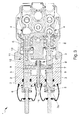
Figure 1 is a sectional view of a device according to the invention in a first embodiment, with the thrust elements in the idle configuration; -
Figure 2 is a sectional view of the device ofFigure 1 with a thrust element in the maximum braking configuration; -
Figure 3 is a sectional view of the device ofFigure 1 with the connection element resting against the abutment means; -
Figure 4 is a sectional view of a device according to the invention in a second embodiment, with the thrust elements in the idle configuration; -
Figure 5 is a sectional view of a device according to the invention in a further embodiment, with the thrust elements in the idle configuration. - With particular reference to such figures, globally indicated by reference number 1 is a braking device for agricultural machines.
- The device 1 comprises a
body 2 which supports in a sliding way at least twothrust elements 3 which can be operated by means of relative braking pedals (not shown in the illustrations) which can be operated by an operator and which are suitable for interacting with relative valves to brake at least a right wheel and at least a left wheel of the corresponding vehicle. - It is known that the braking valves are equipped with elastic contrast means E, on which acts the extremity of the
relative thrust element 3, and that the corresponding shutter is free to act on the work fluid flow so as to reach from time to time a position of balance between the pressure applied on it by the elastic means E and the pressure of the fluid conveyed to the braking system. The structure and operation of the braking valves, identified in the illustrations by thereference number 4 are considered as being known to the technician in the field and are not therefore illustrated in detail below. - Each
thrust element 3 is mobile in translation between an idle configuration, wherein the corresponding braking valve connects the supply of the work fluid to the drain, and a maximum braking configuration, to which corresponds the maximum braking pressure. The idle configuration and the maximum braking configuration correspond to the end-of-stroke positions of thethrust elements 3, the sliding direction of which is identified in the illustrations by means of thedouble arrow 5. - During the stroke from the idle configuration towards the maximum braking configuration, each
thrust element 3 passes through a plurality of intermediate braking configurations, to which correspond braking pressures which are lower than the maximum producible one. - Between the
body 2 and eachthrust element 3 elastic means 6 are placed such as, e.g., a helical spring, suitable for contrasting the shift of the thrust elements themselves from the idle configuration towards the braking configuration. According to the invention, the device 1 comprises at least aconnection element 7 having at least twoconnection areas 8, each of which is associated at least in a rotating way with arelative thrust element 3. Theconnection element 7 is therefore suitable for reciprocally connecting thethrust elements 3 and at the same time allowing these to operate independently. - Suitably, the
connection element 7 is of the rigid type and therefore acts as a rocker arm. - The device 1 also comprises abutment means 9 suitable for contacting the
connection element 7 during the translation of both thethrust elements 3 to limit the forward movement of the latter towards the maximum braking configuration. The abutment means 9 and theconnection element 7 are reciprocally mobile along thesliding direction 5. - The interaction between the abutment means 9 and the
connection element 7 thus allows limiting the braking pressure during the simultaneous operation of the braking pedals (service braking) to a preset value below the maximum achievable one. - The position of the abutment means 9 therefore defines the maximum stroke that can be covered by the
thrust elements 3 during service braking and, consequently, also the corresponding value of the braking pressure. - Suitably, the
connection element 7 is of the rigid type. - Advantageously, the
connection areas 8 correspond to the opposite extremities of theconnection element 7 and have a substantially spherical conformation.Such connection areas 8 are inserted within relative seats obtained on eachthrust element 3. - The seats within which the
connection areas 8 are housed have relative flares suitable for allowing the rotation of theconnection element 7. - In a first type of the device in question, to which belong the embodiments shown in the figures from 1 to 4, the abutment means 9 are associated, during use, integral with the
body 2. In other words, in this first type, during the operation of the device in question, the position of the abutment means 9 is fixed with respect to thebody 2. - More in detail, in this first type, the device 1 comprises at least a
guide element 10 associated integral with thebody 2 and supporting the abutment means 9. Theconnection element 7 is fitted sliding on theguide element 10 and is mobile with respect to this by a predefined angle. More in particular, theconnection element 7 has, in correspondence to its central portion, athrough hole 7a through which theguide element 10 is fitted and which has two opposite flares diverging towards the outside suitable for allowing the rotation of theconnection element 7 with respect to the guide element itself. Theconnection element 7 is therefore able to turn with respect to theguide element 10 until the walls of one of the flares come into contact with the outer surface of theguide element 10. - Advantageously, the position of the abutment means 9 is adjustable along the
sliding direction 5 with respect to thebody 2. More in particular, the abutment means 9 can be screwed onto theguide element 10 or, alternatively, the position of theguide element 10 can be adjusted along thesliding direction 5 with respect to the body 2 (e.g., by means of a threaded connection), in such a way as to allow the adjustment of the position of the abutment means 9 and, therefore, of the limit switch of theconnection element 7 during service braking. - In a first embodiment, shown in the figures from 1 to 3, the abutment means 9 comprise at least an
elastic element 11 suitable for contrasting the shift of thethrust elements 3 towards the maximum braking position. More in particular, the abutment means 9 comprise at least anabutment element 12 suitable for contacting theconnection element 7 and associated with theelastic element 11, such as a spring of desired rigidity, in turn placed between theabutment element 12 and alocator surface 13 integral with theguide element 10. Suitably, one of the above-mentioned flares, and in particular that turned towards the abutment means 9, defines thestop surface 14 against which theabutment element 12 rests following the forward movement of theconnection element 7. In this first embodiment, theelastic element 11 permits the further raising of the braking pressure not proportionate to the increase in force applied to the braking pedal for any emergency stops. - In an alternative embodiment (not shown in the illustrations), the
elastic element 11 with which the abutment means 9 are equipped is of the pre-compressed type. This further increases, with respect to the first embodiment described above, the force which the operator has to apply to achieve the subsequent increase in braking pressure. - In a second embodiment, shown in
figure 4 , the abutment means 9 are of the fixed type such as a protrusion defined by theguide element 10 or, alternatively, by an elastic ring keyed on the guide element itself. - In a second type of the device forming the subject of this invention, shown in
figure 5 , theconnection element 7 is blocked in rotation with respect to thebody 2 and has arotation fulcrum 15 placed between theconnection areas 8. In this further embodiment, the abutment means 9 are defined by thethrust elements 3. Advantageously, thethrust elements 3 haverelative housing seats 16 with elongated shape and inside which theconnection areas 8 are housed sliding.Such housing seats 16 define the abutment means 9 and, more in particular, have arelative abutment surface 17 suitable for contacting theconnection areas 8 following the forward movement of therelative thrust element 3 towards the braking configuration. In this second type of braking device, it is therefore the abutment means 9 which move along thesliding direction 5 with respect to theconnection element 7. - It therefore appears evident how in this second type, it is the length of the
housing seats 16, and more in particular the position of therelative abutment surfaces 17, which determines the maximum stroke that can be covered by thethrust elements 3, and therefore the corresponding pressure value, during service braking. - The operation of the present invention is as follows.
- In the first described type of braking device according to the invention, following the operation of just one of the braking pedals of the vehicle, the
relative thrust element 3 is moved from the idle configuration (shown in thefigures 1 and4 , of the first and the second described embodiment respectively) towards the maximum braking configuration, in contrast to the relativeelastic means 6. Such shift causes the rotation of theconnection element 7 around an axis passing through its median area fitted around the guide element 10 (as shown infigure 2 ) and therefore also the rotation of theconnection areas 8 inside the relative seats. - By individually operating each braking pedal, the
relative thrust element 3 can therefore cover the entire stroke and reach the maximum braking configuration. In the case, instead, of the operator operating both braking pedals together, thethrust elements 3 move towards the maximum braking configuration, also dragging theconnection element 7, which therefore moves with respect to theguide element 10. The shift of thethrust elements 3 is interrupted the moment theconnection element 7 contacts the abutment means 9, as shown infigure 3 . It is therefore easy to appreciate how, by regulating the position of the abutment means 9, is it possible to intervene on the maximum stroke which thethrust elements 3 can cover during service braking (i.e., when both brake pedals are operated by the operator), and consequently on the maximum braking pressure applicable in this operating condition. - In the event of the operator initially operating a first braking pedal, bringing the
relative thrust element 3 to the end-of-stroke position, and subsequently also intervening on the other (while maintaining the first one in operation), thethrust element 3 corresponding to the second operated pedal will have free stroke until theconnection element 7 contacts the abutment means 9, after which it applies a force on thefirst thrust element 3 such as to cause it to move towards the idle configuration so as to balance the braking pressure value corresponding to the second operatedthrust element 3. - As already said above, in the event of the abutment means 9 also comprising the
elastic element 11, the latter permits making mobile under load the stop of theconnection element 7, which can therefore complete a further stroke to increase the braking pressure. It appears evident how the force that has to be applied by the operator to compress theelastic element 11 depends on the rigidity and any preloading of the elastic element itself. - The second type of braking device forming the subject of the present invention described above envisages that the
connection element 7 be blocked in translation with respect to thebody 2 and, therefore, that it be free to rotate around itscentral fulcrum 15. - More in particular, following the operation of a braking pedal and the consequent shift of the
relative thrust element 3, theconnection element 7 rotates around its owncentral fulcrum 15 and itsconnection area 8 associated withsuch thrust element 3 moves inside therelative housing seat 16. - In the event of the operator operating both braking pedals at the same time for service braking, the
thrust elements 3 move towards the maximum braking configuration. During such shift, both theconnection areas 8 slide inside therelative housing seats 16 until they come into contact with the corresponding abutment surfaces 17. Because, as has been said above, theconnection element 7 can rotate around itsown fulcrum 15 but is blocked in translation, once the abutment surfaces 17 contact theconnection areas 8 thethrust elements 3 are consequently blocked as regards their shift towards the relative end-of-stroke position. - In this second type of braking device, it is therefore the position of the abutment surfaces 17 that defines the maximum stroke which the thrust elements can cover during service braking.
- It has in practice been ascertained how the described invention achieves the proposed objects and in particular the fact is underlined that the braking device forming the subject of the present invention permits automatically regulating the maximum braking pressure according to the operating conditions of the vehicle, i.e., depending on whether the latter is in steering or braking phase.
Claims (11)
- Braking device (1) for agricultural machines comprising:a body (2) which supports in a sliding way at least two thrust elements (3) operatively connectable to relative valves (4) for the braking of a right wheel and of a left wheel of a vehicle and associable with respective braking pedals that can be operated by an operator, said thrust elements (3) being mobile along a sliding direction (5) between an idle configuration and a maximum braking configuration,characterized by the fact that it comprises at least a connection element (7) having at least two connection areas (8), each of which is associated at least in a rotating way with a relative thrust element (3) to connect them reciprocally andto allow the independent operation of the braking pedals and by the fact that it comprises abutment means (9) suitable for contacting said connection element (7) during the translation of both said thrust elements (3) to limit their forward movement towards the maximum braking configuration, said connection element (7) and said abutment means (9) being reciprocally mobile along said sliding direction (5).
- Device (1) according to claim 1, characterized by the fact that said connection element (7) is of the rigid type.
- Device (1) according to claim 1 or 2, characterized by the fact that said abutment means (9) are integrally associated, during use, with said body (2).
- Device (1) according to claim 3, characterized by the fact that the position of said abutment means (9) is adjustable along said sliding direction (5) with respect to said body (2).
- Device (1) according to claim 3 or 4, characterized by the fact that it comprises at least a guide element (10) integrally associated with said body (2) and supporting said abutment means (9), said connection element (7) being fitted sliding on said guide element (10) and being mobile in rotation with respect to it by a predefined angle.
- Device (1) according to one or more of the preceding claims, characterized by the fact that said abutment means (9) are of the fixed type.
- Device (1) according to one or more of the preceding claims, characterized by the fact that said abutment means (9) comprise at least an elastic element (11) suitable for contrasting the shift of said connection element (7) towards said maximum braking configuration.
- Device (1) according to claim 7, characterized by the fact that said elastic element (11) is of the pre-compressed type.
- Device (1) according to claim 1 or 2, characterized by the fact that said connection element (7) is blocked in translation with respect to said body (2) and has a rotation fulcrum placed between said connection areas (8) and by the fact that said abutment means (9) are defined by said thrust elements (3).
- Device (1) according to claim 9, characterized by the fact that said thrust elements (3) have relative housing seats with an elongated conformation and inside which are housed sliding said connection areas (8), said housing seats defining said abutment means (9).
- Device (1) according to claim 10, characterized by the fact that said housing seats define an abutment surface suitable for contacting said connection areas (8) following the forward movement of the relative thrust element (3) towards said maximum braking configuration.
Applications Claiming Priority (1)
| Application Number | Priority Date | Filing Date | Title |
|---|---|---|---|
| IT000256A ITMO20130256A1 (en) | 2013-09-20 | 2013-09-20 | BRAKING DEVICE FOR AGRICULTURAL MACHINES |
Publications (2)
| Publication Number | Publication Date |
|---|---|
| EP2851248A1 true EP2851248A1 (en) | 2015-03-25 |
| EP2851248B1 EP2851248B1 (en) | 2018-05-16 |
Family
ID=49554391
Family Applications (1)
| Application Number | Title | Priority Date | Filing Date |
|---|---|---|---|
| EP14185474.5A Active EP2851248B1 (en) | 2013-09-20 | 2014-09-19 | Braking device for agricultural machines |
Country Status (4)
| Country | Link |
|---|---|
| US (1) | US9457778B2 (en) |
| EP (1) | EP2851248B1 (en) |
| BR (1) | BR102014023453B1 (en) |
| IT (1) | ITMO20130256A1 (en) |
Citations (12)
| Publication number | Priority date | Publication date | Assignee | Title |
|---|---|---|---|---|
| US2741337A (en) * | 1951-04-18 | 1956-04-10 | Int Harvester Co | Selective vehicle brake-engaging apparatus |
| US3640067A (en) * | 1969-05-08 | 1972-02-08 | Girling Ltd | Two-pedal hydraulic braking system |
| DE2253941A1 (en) * | 1968-06-21 | 1973-05-10 | Girling Ltd | HYDRAULIC STEERING BRAKE DEVICE FOR MOTOR VEHICLES |
| FR2450726A1 (en) * | 1979-03-09 | 1980-10-03 | Teves Gmbh Alfred | DIRECTIONAL BRAKING DEVICE FOR HYDRAULIC BRAKING VEHICLE |
| GB2113786A (en) * | 1982-01-27 | 1983-08-10 | Teves Gmbh Alfred | Combined braking and steering brake system for vehicles |
| DE3243366A1 (en) * | 1982-11-24 | 1984-05-24 | Alfred Teves Gmbh, 6000 Frankfurt | Control device for a hydraulic braking and steering brake system |
| GB2140516A (en) * | 1983-05-25 | 1984-11-28 | Automotive Products Plc | Hydraulic braking system |
| DE10145789A1 (en) * | 2001-09-17 | 2003-04-10 | Continental Teves Ag & Co Ohg | Steering braking system with electrically controlled valves |
| EP1459951A1 (en) * | 2003-03-18 | 2004-09-22 | Studio Tecnico 6 M S.R.L. | Valve for braking system |
| WO2005051743A1 (en) * | 2003-11-25 | 2005-06-09 | Carlisle Brake Products (Uk) Limited | Twin master cylinder assembly |
| GB2466066A (en) * | 2008-12-12 | 2010-06-16 | Agco Gmbh | Braking system having left and right brake pedals that are lockable together, and warning means to indicate the pedals are unlocked |
| WO2011010245A1 (en) * | 2009-07-22 | 2011-01-27 | Vhit S.P.A. | Master cylinder assembly for balancing braking systems of an agricultural vehicle |
-
2013
- 2013-09-20 IT IT000256A patent/ITMO20130256A1/en unknown
-
2014
- 2014-09-19 EP EP14185474.5A patent/EP2851248B1/en active Active
- 2014-09-22 BR BR102014023453-5A patent/BR102014023453B1/en active IP Right Grant
- 2014-09-22 US US14/492,158 patent/US9457778B2/en active Active
Patent Citations (12)
| Publication number | Priority date | Publication date | Assignee | Title |
|---|---|---|---|---|
| US2741337A (en) * | 1951-04-18 | 1956-04-10 | Int Harvester Co | Selective vehicle brake-engaging apparatus |
| DE2253941A1 (en) * | 1968-06-21 | 1973-05-10 | Girling Ltd | HYDRAULIC STEERING BRAKE DEVICE FOR MOTOR VEHICLES |
| US3640067A (en) * | 1969-05-08 | 1972-02-08 | Girling Ltd | Two-pedal hydraulic braking system |
| FR2450726A1 (en) * | 1979-03-09 | 1980-10-03 | Teves Gmbh Alfred | DIRECTIONAL BRAKING DEVICE FOR HYDRAULIC BRAKING VEHICLE |
| GB2113786A (en) * | 1982-01-27 | 1983-08-10 | Teves Gmbh Alfred | Combined braking and steering brake system for vehicles |
| DE3243366A1 (en) * | 1982-11-24 | 1984-05-24 | Alfred Teves Gmbh, 6000 Frankfurt | Control device for a hydraulic braking and steering brake system |
| GB2140516A (en) * | 1983-05-25 | 1984-11-28 | Automotive Products Plc | Hydraulic braking system |
| DE10145789A1 (en) * | 2001-09-17 | 2003-04-10 | Continental Teves Ag & Co Ohg | Steering braking system with electrically controlled valves |
| EP1459951A1 (en) * | 2003-03-18 | 2004-09-22 | Studio Tecnico 6 M S.R.L. | Valve for braking system |
| WO2005051743A1 (en) * | 2003-11-25 | 2005-06-09 | Carlisle Brake Products (Uk) Limited | Twin master cylinder assembly |
| GB2466066A (en) * | 2008-12-12 | 2010-06-16 | Agco Gmbh | Braking system having left and right brake pedals that are lockable together, and warning means to indicate the pedals are unlocked |
| WO2011010245A1 (en) * | 2009-07-22 | 2011-01-27 | Vhit S.P.A. | Master cylinder assembly for balancing braking systems of an agricultural vehicle |
Also Published As
| Publication number | Publication date |
|---|---|
| BR102014023453B1 (en) | 2022-06-28 |
| BR102014023453A2 (en) | 2015-09-08 |
| US20150084400A1 (en) | 2015-03-26 |
| ITMO20130256A1 (en) | 2015-03-21 |
| EP2851248B1 (en) | 2018-05-16 |
| US9457778B2 (en) | 2016-10-04 |
Similar Documents
| Publication | Publication Date | Title |
|---|---|---|
| US8177306B2 (en) | Two master cylinder braking system for a vehicle having a safety function | |
| WO2008071437A3 (en) | Adaptive free-travel reduction | |
| EP2170669B1 (en) | Hydraulic device for actuating the braking of work vehicles and the like | |
| US20120222924A1 (en) | Interface member for a bicycle brake | |
| EP2371642B1 (en) | Flow adjustment device and brake ciruit including such a flow adjustment device | |
| EP3294596B1 (en) | Braking device | |
| EP2851248B1 (en) | Braking device for agricultural machines | |
| CN104895960A (en) | Crane brake and travelling crane | |
| US8342295B2 (en) | Return spring apparatus for a bicycle brake | |
| EP2048049B1 (en) | Device for detecting amount of pedal operation | |
| EP3312066B1 (en) | Device for controlling the braking of a trailer | |
| US8651243B2 (en) | Hydraulic rim brake for a bicycle | |
| US9638220B2 (en) | Control apparatus for vehicles, operating machines or the like | |
| WO2014001876A1 (en) | Braking device of a trailer | |
| TWI687789B (en) | Master unit | |
| EP2876009B1 (en) | Piloting device for piloting a braking valve of a trailer | |
| EP3283033B1 (en) | Wheelchair braking and steering system | |
| EP4054907B1 (en) | Device for controlling the braking of a trailer | |
| EP3319848A1 (en) | Actuating device of a valve for the braking of a trailer | |
| EP2896538A1 (en) | Proportional valve associable with a control device, particularly with the pump-brake of a vehicle | |
| US4351571A (en) | Dual-circuit pressure control valves for brake systems | |
| GB1219403A (en) | Vehicle fluid pressure operated anti-skid braking systems |
Legal Events
| Date | Code | Title | Description |
|---|---|---|---|
| PUAI | Public reference made under article 153(3) epc to a published international application that has entered the european phase |
Free format text: ORIGINAL CODE: 0009012 |
|
| 17P | Request for examination filed |
Effective date: 20140919 |
|
| AK | Designated contracting states |
Kind code of ref document: A1 Designated state(s): AL AT BE BG CH CY CZ DE DK EE ES FI FR GB GR HR HU IE IS IT LI LT LU LV MC MK MT NL NO PL PT RO RS SE SI SK SM TR |
|
| AX | Request for extension of the european patent |
Extension state: BA ME |
|
| R17P | Request for examination filed (corrected) |
Effective date: 20150424 |
|
| RBV | Designated contracting states (corrected) |
Designated state(s): AL AT BE BG CH CY CZ DE DK EE ES FI FR GB GR HR HU IE IS IT LI LT LU LV MC MK MT NL NO PL PT RO RS SE SI SK SM TR |
|
| GRAP | Despatch of communication of intention to grant a patent |
Free format text: ORIGINAL CODE: EPIDOSNIGR1 |
|
| STAA | Information on the status of an ep patent application or granted ep patent |
Free format text: STATUS: GRANT OF PATENT IS INTENDED |
|
| RAP1 | Party data changed (applicant data changed or rights of an application transferred) |
Owner name: STUDIO TECNICO 6 M S.R.L. |
|
| INTG | Intention to grant announced |
Effective date: 20171204 |
|
| 111Z | Information provided on other rights and legal means of execution |
Free format text: AL AT BE BG CH CY CZ DE DK EE ES FI FR GB GR HR HU IE IS IT LT LU LV MC MK MT NL NO PL PT RO RS SE SI SK SM TR Effective date: 20180208 |
|
| RAP1 | Party data changed (applicant data changed or rights of an application transferred) |
Owner name: SAFIM S.P.A. |
|
| GRAS | Grant fee paid |
Free format text: ORIGINAL CODE: EPIDOSNIGR3 |
|
| GRAA | (expected) grant |
Free format text: ORIGINAL CODE: 0009210 |
|
| STAA | Information on the status of an ep patent application or granted ep patent |
Free format text: STATUS: THE PATENT HAS BEEN GRANTED |
|
| RIN1 | Information on inventor provided before grant (corrected) |
Inventor name: MAMEI, ERONNE Inventor name: MAMEI, ANDREA Inventor name: MAMEI, ENRICO |
|
| AK | Designated contracting states |
Kind code of ref document: B1 Designated state(s): AL AT BE BG CH CY CZ DE DK EE ES FI FR GB GR HR HU IE IS IT LI LT LU LV MC MK MT NL NO PL PT RO RS SE SI SK SM TR |
|
| REG | Reference to a national code |
Ref country code: GB Ref legal event code: FG4D |
|
| REG | Reference to a national code |
Ref country code: CH Ref legal event code: EP |
|
| REG | Reference to a national code |
Ref country code: IE Ref legal event code: FG4D |
|
| REG | Reference to a national code |
Ref country code: DE Ref legal event code: R096 Ref document number: 602014025467 Country of ref document: DE |
|
| REG | Reference to a national code |
Ref country code: AT Ref legal event code: REF Ref document number: 999259 Country of ref document: AT Kind code of ref document: T Effective date: 20180615 |
|
| REG | Reference to a national code |
Ref country code: DE Ref legal event code: R082 Ref document number: 602014025467 Country of ref document: DE |
|
| REG | Reference to a national code |
Ref country code: NL Ref legal event code: MP Effective date: 20180516 |
|
| REG | Reference to a national code |
Ref country code: LT Ref legal event code: MG4D |
|
| PG25 | Lapsed in a contracting state [announced via postgrant information from national office to epo] |
Ref country code: LT Free format text: LAPSE BECAUSE OF FAILURE TO SUBMIT A TRANSLATION OF THE DESCRIPTION OR TO PAY THE FEE WITHIN THE PRESCRIBED TIME-LIMIT Effective date: 20180516 Ref country code: ES Free format text: LAPSE BECAUSE OF FAILURE TO SUBMIT A TRANSLATION OF THE DESCRIPTION OR TO PAY THE FEE WITHIN THE PRESCRIBED TIME-LIMIT Effective date: 20180516 Ref country code: FI Free format text: LAPSE BECAUSE OF FAILURE TO SUBMIT A TRANSLATION OF THE DESCRIPTION OR TO PAY THE FEE WITHIN THE PRESCRIBED TIME-LIMIT Effective date: 20180516 Ref country code: NO Free format text: LAPSE BECAUSE OF FAILURE TO SUBMIT A TRANSLATION OF THE DESCRIPTION OR TO PAY THE FEE WITHIN THE PRESCRIBED TIME-LIMIT Effective date: 20180816 Ref country code: SE Free format text: LAPSE BECAUSE OF FAILURE TO SUBMIT A TRANSLATION OF THE DESCRIPTION OR TO PAY THE FEE WITHIN THE PRESCRIBED TIME-LIMIT Effective date: 20180516 Ref country code: BG Free format text: LAPSE BECAUSE OF FAILURE TO SUBMIT A TRANSLATION OF THE DESCRIPTION OR TO PAY THE FEE WITHIN THE PRESCRIBED TIME-LIMIT Effective date: 20180816 |
|
| PG25 | Lapsed in a contracting state [announced via postgrant information from national office to epo] |
Ref country code: NL Free format text: LAPSE BECAUSE OF FAILURE TO SUBMIT A TRANSLATION OF THE DESCRIPTION OR TO PAY THE FEE WITHIN THE PRESCRIBED TIME-LIMIT Effective date: 20180516 Ref country code: RS Free format text: LAPSE BECAUSE OF FAILURE TO SUBMIT A TRANSLATION OF THE DESCRIPTION OR TO PAY THE FEE WITHIN THE PRESCRIBED TIME-LIMIT Effective date: 20180516 Ref country code: HR Free format text: LAPSE BECAUSE OF FAILURE TO SUBMIT A TRANSLATION OF THE DESCRIPTION OR TO PAY THE FEE WITHIN THE PRESCRIBED TIME-LIMIT Effective date: 20180516 Ref country code: GR Free format text: LAPSE BECAUSE OF FAILURE TO SUBMIT A TRANSLATION OF THE DESCRIPTION OR TO PAY THE FEE WITHIN THE PRESCRIBED TIME-LIMIT Effective date: 20180817 Ref country code: LV Free format text: LAPSE BECAUSE OF FAILURE TO SUBMIT A TRANSLATION OF THE DESCRIPTION OR TO PAY THE FEE WITHIN THE PRESCRIBED TIME-LIMIT Effective date: 20180516 |
|
| REG | Reference to a national code |
Ref country code: AT Ref legal event code: MK05 Ref document number: 999259 Country of ref document: AT Kind code of ref document: T Effective date: 20180516 |
|
| PG25 | Lapsed in a contracting state [announced via postgrant information from national office to epo] |
Ref country code: CZ Free format text: LAPSE BECAUSE OF FAILURE TO SUBMIT A TRANSLATION OF THE DESCRIPTION OR TO PAY THE FEE WITHIN THE PRESCRIBED TIME-LIMIT Effective date: 20180516 Ref country code: AT Free format text: LAPSE BECAUSE OF FAILURE TO SUBMIT A TRANSLATION OF THE DESCRIPTION OR TO PAY THE FEE WITHIN THE PRESCRIBED TIME-LIMIT Effective date: 20180516 Ref country code: DK Free format text: LAPSE BECAUSE OF FAILURE TO SUBMIT A TRANSLATION OF THE DESCRIPTION OR TO PAY THE FEE WITHIN THE PRESCRIBED TIME-LIMIT Effective date: 20180516 Ref country code: EE Free format text: LAPSE BECAUSE OF FAILURE TO SUBMIT A TRANSLATION OF THE DESCRIPTION OR TO PAY THE FEE WITHIN THE PRESCRIBED TIME-LIMIT Effective date: 20180516 Ref country code: SK Free format text: LAPSE BECAUSE OF FAILURE TO SUBMIT A TRANSLATION OF THE DESCRIPTION OR TO PAY THE FEE WITHIN THE PRESCRIBED TIME-LIMIT Effective date: 20180516 Ref country code: RO Free format text: LAPSE BECAUSE OF FAILURE TO SUBMIT A TRANSLATION OF THE DESCRIPTION OR TO PAY THE FEE WITHIN THE PRESCRIBED TIME-LIMIT Effective date: 20180516 Ref country code: PL Free format text: LAPSE BECAUSE OF FAILURE TO SUBMIT A TRANSLATION OF THE DESCRIPTION OR TO PAY THE FEE WITHIN THE PRESCRIBED TIME-LIMIT Effective date: 20180516 |
|
| REG | Reference to a national code |
Ref country code: DE Ref legal event code: R097 Ref document number: 602014025467 Country of ref document: DE |
|
| PG25 | Lapsed in a contracting state [announced via postgrant information from national office to epo] |
Ref country code: SM Free format text: LAPSE BECAUSE OF FAILURE TO SUBMIT A TRANSLATION OF THE DESCRIPTION OR TO PAY THE FEE WITHIN THE PRESCRIBED TIME-LIMIT Effective date: 20180516 |
|
| PLBE | No opposition filed within time limit |
Free format text: ORIGINAL CODE: 0009261 |
|
| STAA | Information on the status of an ep patent application or granted ep patent |
Free format text: STATUS: NO OPPOSITION FILED WITHIN TIME LIMIT |
|
| 26N | No opposition filed |
Effective date: 20190219 |
|
| PG25 | Lapsed in a contracting state [announced via postgrant information from national office to epo] |
Ref country code: MC Free format text: LAPSE BECAUSE OF FAILURE TO SUBMIT A TRANSLATION OF THE DESCRIPTION OR TO PAY THE FEE WITHIN THE PRESCRIBED TIME-LIMIT Effective date: 20180516 |
|
| REG | Reference to a national code |
Ref country code: CH Ref legal event code: PL |
|
| GBPC | Gb: european patent ceased through non-payment of renewal fee |
Effective date: 20180919 |
|
| PG25 | Lapsed in a contracting state [announced via postgrant information from national office to epo] |
Ref country code: SI Free format text: LAPSE BECAUSE OF FAILURE TO SUBMIT A TRANSLATION OF THE DESCRIPTION OR TO PAY THE FEE WITHIN THE PRESCRIBED TIME-LIMIT Effective date: 20180516 |
|
| REG | Reference to a national code |
Ref country code: BE Ref legal event code: MM Effective date: 20180930 |
|
| REG | Reference to a national code |
Ref country code: IE Ref legal event code: MM4A |
|
| PG25 | Lapsed in a contracting state [announced via postgrant information from national office to epo] |
Ref country code: LU Free format text: LAPSE BECAUSE OF NON-PAYMENT OF DUE FEES Effective date: 20180919 |
|
| PG25 | Lapsed in a contracting state [announced via postgrant information from national office to epo] |
Ref country code: IE Free format text: LAPSE BECAUSE OF NON-PAYMENT OF DUE FEES Effective date: 20180919 |
|
| PG25 | Lapsed in a contracting state [announced via postgrant information from national office to epo] |
Ref country code: FR Free format text: LAPSE BECAUSE OF NON-PAYMENT OF DUE FEES Effective date: 20180930 Ref country code: BE Free format text: LAPSE BECAUSE OF NON-PAYMENT OF DUE FEES Effective date: 20180930 Ref country code: CH Free format text: LAPSE BECAUSE OF NON-PAYMENT OF DUE FEES Effective date: 20180930 Ref country code: LI Free format text: LAPSE BECAUSE OF NON-PAYMENT OF DUE FEES Effective date: 20180930 |
|
| PG25 | Lapsed in a contracting state [announced via postgrant information from national office to epo] |
Ref country code: GB Free format text: LAPSE BECAUSE OF NON-PAYMENT OF DUE FEES Effective date: 20180919 |
|
| PG25 | Lapsed in a contracting state [announced via postgrant information from national office to epo] |
Ref country code: AL Free format text: LAPSE BECAUSE OF FAILURE TO SUBMIT A TRANSLATION OF THE DESCRIPTION OR TO PAY THE FEE WITHIN THE PRESCRIBED TIME-LIMIT Effective date: 20180516 |
|
| PG25 | Lapsed in a contracting state [announced via postgrant information from national office to epo] |
Ref country code: MT Free format text: LAPSE BECAUSE OF NON-PAYMENT OF DUE FEES Effective date: 20180919 |
|
| PG25 | Lapsed in a contracting state [announced via postgrant information from national office to epo] |
Ref country code: TR Free format text: LAPSE BECAUSE OF FAILURE TO SUBMIT A TRANSLATION OF THE DESCRIPTION OR TO PAY THE FEE WITHIN THE PRESCRIBED TIME-LIMIT Effective date: 20180516 |
|
| PG25 | Lapsed in a contracting state [announced via postgrant information from national office to epo] |
Ref country code: PT Free format text: LAPSE BECAUSE OF FAILURE TO SUBMIT A TRANSLATION OF THE DESCRIPTION OR TO PAY THE FEE WITHIN THE PRESCRIBED TIME-LIMIT Effective date: 20180516 Ref country code: HU Free format text: LAPSE BECAUSE OF FAILURE TO SUBMIT A TRANSLATION OF THE DESCRIPTION OR TO PAY THE FEE WITHIN THE PRESCRIBED TIME-LIMIT; INVALID AB INITIO Effective date: 20140919 |
|
| PG25 | Lapsed in a contracting state [announced via postgrant information from national office to epo] |
Ref country code: CY Free format text: LAPSE BECAUSE OF FAILURE TO SUBMIT A TRANSLATION OF THE DESCRIPTION OR TO PAY THE FEE WITHIN THE PRESCRIBED TIME-LIMIT Effective date: 20180516 Ref country code: MK Free format text: LAPSE BECAUSE OF NON-PAYMENT OF DUE FEES Effective date: 20180516 |
|
| PG25 | Lapsed in a contracting state [announced via postgrant information from national office to epo] |
Ref country code: IS Free format text: LAPSE BECAUSE OF FAILURE TO SUBMIT A TRANSLATION OF THE DESCRIPTION OR TO PAY THE FEE WITHIN THE PRESCRIBED TIME-LIMIT Effective date: 20180916 |
|
| P01 | Opt-out of the competence of the unified patent court (upc) registered |
Effective date: 20230527 |
|
| PGFP | Annual fee paid to national office [announced via postgrant information from national office to epo] |
Ref country code: IT Payment date: 20230920 Year of fee payment: 10 |
|
| PGFP | Annual fee paid to national office [announced via postgrant information from national office to epo] |
Ref country code: DE Payment date: 20240927 Year of fee payment: 11 |