EP2851176A1 - Machine for forming containers made of thermoplastic material - Google Patents
Machine for forming containers made of thermoplastic material Download PDFInfo
- Publication number
- EP2851176A1 EP2851176A1 EP14184220.3A EP14184220A EP2851176A1 EP 2851176 A1 EP2851176 A1 EP 2851176A1 EP 14184220 A EP14184220 A EP 14184220A EP 2851176 A1 EP2851176 A1 EP 2851176A1
- Authority
- EP
- European Patent Office
- Prior art keywords
- blowing
- preforms
- station
- mould
- moulding
- Prior art date
- Legal status (The legal status is an assumption and is not a legal conclusion. Google has not performed a legal analysis and makes no representation as to the accuracy of the status listed.)
- Granted
Links
- 239000012815 thermoplastic material Substances 0.000 title claims abstract description 14
- 238000007664 blowing Methods 0.000 claims abstract description 188
- 238000002347 injection Methods 0.000 claims abstract description 61
- 239000007924 injection Substances 0.000 claims abstract description 61
- 238000000465 moulding Methods 0.000 claims abstract description 54
- 238000000071 blow moulding Methods 0.000 claims abstract description 6
- 238000000034 method Methods 0.000 claims description 7
- 238000006073 displacement reaction Methods 0.000 claims description 4
- 238000011144 upstream manufacturing Methods 0.000 claims description 3
- 238000004519 manufacturing process Methods 0.000 description 14
- 238000001816 cooling Methods 0.000 description 4
- 239000000463 material Substances 0.000 description 4
- 229920000139 polyethylene terephthalate Polymers 0.000 description 4
- 239000005020 polyethylene terephthalate Substances 0.000 description 4
- 238000000605 extraction Methods 0.000 description 2
- 230000003750 conditioning effect Effects 0.000 description 1
- 238000003780 insertion Methods 0.000 description 1
- 230000037431 insertion Effects 0.000 description 1
- 239000007788 liquid Substances 0.000 description 1
- 239000011344 liquid material Substances 0.000 description 1
- 238000004806 packaging method and process Methods 0.000 description 1
- -1 polyethylene terephthalate Polymers 0.000 description 1
- 239000000843 powder Substances 0.000 description 1
- 238000002360 preparation method Methods 0.000 description 1
- 239000000243 solution Substances 0.000 description 1
- 229920001169 thermoplastic Polymers 0.000 description 1
- 239000004416 thermosoftening plastic Substances 0.000 description 1
Images


Classifications
-
- B—PERFORMING OPERATIONS; TRANSPORTING
- B29—WORKING OF PLASTICS; WORKING OF SUBSTANCES IN A PLASTIC STATE IN GENERAL
- B29C—SHAPING OR JOINING OF PLASTICS; SHAPING OF MATERIAL IN A PLASTIC STATE, NOT OTHERWISE PROVIDED FOR; AFTER-TREATMENT OF THE SHAPED PRODUCTS, e.g. REPAIRING
- B29C49/00—Blow-moulding, i.e. blowing a preform or parison to a desired shape within a mould; Apparatus therefor
- B29C49/02—Combined blow-moulding and manufacture of the preform or the parison
- B29C49/06—Injection blow-moulding
- B29C49/061—Injection blow-moulding with parison holding means displaceable between injection and blow stations
-
- B—PERFORMING OPERATIONS; TRANSPORTING
- B29—WORKING OF PLASTICS; WORKING OF SUBSTANCES IN A PLASTIC STATE IN GENERAL
- B29C—SHAPING OR JOINING OF PLASTICS; SHAPING OF MATERIAL IN A PLASTIC STATE, NOT OTHERWISE PROVIDED FOR; AFTER-TREATMENT OF THE SHAPED PRODUCTS, e.g. REPAIRING
- B29C49/00—Blow-moulding, i.e. blowing a preform or parison to a desired shape within a mould; Apparatus therefor
- B29C49/42—Component parts, details or accessories; Auxiliary operations
- B29C49/56—Opening, closing or clamping means
-
- B—PERFORMING OPERATIONS; TRANSPORTING
- B29—WORKING OF PLASTICS; WORKING OF SUBSTANCES IN A PLASTIC STATE IN GENERAL
- B29C—SHAPING OR JOINING OF PLASTICS; SHAPING OF MATERIAL IN A PLASTIC STATE, NOT OTHERWISE PROVIDED FOR; AFTER-TREATMENT OF THE SHAPED PRODUCTS, e.g. REPAIRING
- B29C49/00—Blow-moulding, i.e. blowing a preform or parison to a desired shape within a mould; Apparatus therefor
- B29C49/02—Combined blow-moulding and manufacture of the preform or the parison
- B29C2049/023—Combined blow-moulding and manufacture of the preform or the parison using inherent heat of the preform, i.e. 1 step blow moulding
-
- B—PERFORMING OPERATIONS; TRANSPORTING
- B29—WORKING OF PLASTICS; WORKING OF SUBSTANCES IN A PLASTIC STATE IN GENERAL
- B29C—SHAPING OR JOINING OF PLASTICS; SHAPING OF MATERIAL IN A PLASTIC STATE, NOT OTHERWISE PROVIDED FOR; AFTER-TREATMENT OF THE SHAPED PRODUCTS, e.g. REPAIRING
- B29C49/00—Blow-moulding, i.e. blowing a preform or parison to a desired shape within a mould; Apparatus therefor
- B29C49/02—Combined blow-moulding and manufacture of the preform or the parison
- B29C49/06—Injection blow-moulding
- B29C49/061—Injection blow-moulding with parison holding means displaceable between injection and blow stations
- B29C49/064—Injection blow-moulding with parison holding means displaceable between injection and blow stations following a rectilinear path, e.g. shuttle-type
-
- B—PERFORMING OPERATIONS; TRANSPORTING
- B29—WORKING OF PLASTICS; WORKING OF SUBSTANCES IN A PLASTIC STATE IN GENERAL
- B29C—SHAPING OR JOINING OF PLASTICS; SHAPING OF MATERIAL IN A PLASTIC STATE, NOT OTHERWISE PROVIDED FOR; AFTER-TREATMENT OF THE SHAPED PRODUCTS, e.g. REPAIRING
- B29C49/00—Blow-moulding, i.e. blowing a preform or parison to a desired shape within a mould; Apparatus therefor
- B29C49/28—Blow-moulding apparatus
- B29C49/28008—Blow-moulding apparatus mounting, exchanging or centering machine parts, e.g. modular parts
-
- B—PERFORMING OPERATIONS; TRANSPORTING
- B29—WORKING OF PLASTICS; WORKING OF SUBSTANCES IN A PLASTIC STATE IN GENERAL
- B29C—SHAPING OR JOINING OF PLASTICS; SHAPING OF MATERIAL IN A PLASTIC STATE, NOT OTHERWISE PROVIDED FOR; AFTER-TREATMENT OF THE SHAPED PRODUCTS, e.g. REPAIRING
- B29C49/00—Blow-moulding, i.e. blowing a preform or parison to a desired shape within a mould; Apparatus therefor
- B29C49/28—Blow-moulding apparatus
- B29C49/30—Blow-moulding apparatus having movable moulds or mould parts
- B29C49/32—Blow-moulding apparatus having movable moulds or mould parts moving "to and fro"
-
- B—PERFORMING OPERATIONS; TRANSPORTING
- B29—WORKING OF PLASTICS; WORKING OF SUBSTANCES IN A PLASTIC STATE IN GENERAL
- B29C—SHAPING OR JOINING OF PLASTICS; SHAPING OF MATERIAL IN A PLASTIC STATE, NOT OTHERWISE PROVIDED FOR; AFTER-TREATMENT OF THE SHAPED PRODUCTS, e.g. REPAIRING
- B29C49/00—Blow-moulding, i.e. blowing a preform or parison to a desired shape within a mould; Apparatus therefor
- B29C49/42—Component parts, details or accessories; Auxiliary operations
- B29C49/56—Opening, closing or clamping means
- B29C49/5601—Mechanically operated, i.e. closing or opening of the mould parts is done by mechanic means
- B29C49/5603—Mechanically operated, i.e. closing or opening of the mould parts is done by mechanic means using toggle mechanism
-
- B—PERFORMING OPERATIONS; TRANSPORTING
- B29—WORKING OF PLASTICS; WORKING OF SUBSTANCES IN A PLASTIC STATE IN GENERAL
- B29L—INDEXING SCHEME ASSOCIATED WITH SUBCLASS B29C, RELATING TO PARTICULAR ARTICLES
- B29L2031/00—Other particular articles
- B29L2031/712—Containers; Packaging elements or accessories, Packages
- B29L2031/7158—Bottles
Definitions
- the present invention relates to a machine for forming containers made of thermoplastic material.
- thermoplastic containers suitable for this purpose.
- said containers are formed in suitable machines comprising a mould into which a predefined quantity of material is injected and then subjected to a first mechanical moulding deformation in order to obtain a so-called "preform" which, in turn, is then subjected to blowing - which may be preceded by a heat conditioning treatment - in order to arrive at the final form of the container.
- said cycle may be divided into two different steps performed on different machines (called single-stage machines) for respectively producing the "preforms" and blow-moulding said preforms in order to obtain the finished container.
- the two production steps may be combined in a single machine called a dual-stage machine.
- the machines comprise an injection mould formed by two half-parts which may close and open to allow injection into the mould of the material in the softened state and the subsequent extraction of the preforms, already cooled; subsequent forming of the container is performed in a second blowing mould downstream of the injection mould.
- This long cooling time is particularly important for preforms made of PET (polyethylene terephthalate) which softens while being fed to the mould at a very high temperature and must instead be brought to temperatures which are much lower for the subsequent blowing operation.
- PET polyethylene terephthalate
- said slowness of the cycle results in the need to increase the dimensions of the moulds in order to be able to obtain a high hourly production output, which however causes major handling difficulties, and therefore renewed slowness in the format-changing operation, as well as a significant increase in the production costs resulting from the cost of the blowing moulds, said cost increasing exponentially with the increase in their dimensions and making handling thereof difficult as a result, further increasing the downtime of the machine during the format-changing operations.
- the technical problem which is posed therefore is that of providing a machine for the production of containers made of thermoplastic material, and in particular PET, by means of blowing of preforms produced by means of moulding within the same machine, which must allow correct cooling of the preforms before they undergo blowing and at the same time a high hourly production output.
- the invention relates to a machine for forming containers made of thermoplastic material by blow-moulding preforms obtained by means of injection/moulding within the machine, for which at least one longitudinal direction for feeding of the preforms between the stations thereof is defined, said machine comprising:
- said movable blowing assembly moves from a first blowing position, where it forms a first series of containers into at least one second blowing position where it forms a second series of containers; and into a third end-of-travel position in the longitudinal direction for allowing movement of the containers towards a following unloading point.
- the blowing assembly may further comprise a blowing mould with a number of blowing cavities equal to a whole submultiple ⁇ 2 of the number of cavities in the mould of the station for moulding the preforms.
- the number of blowing positions of the movable blowing unit corresponds to said whole submultiple ⁇ 2 of the number of cavities in the mould of the station for moulding the preforms.
- blowing assembly displaceable between the various positions determined by subdividing the blowing moulds with respect to the injection mould, it is possible to vary very rapidly the number of positions of the blowing mould upon variation in the format and number of containers to be formed and therefore of the moulds, reducing the downtime of the machine and ensuring optimal cooling times.
- said blowing assembly is moved in the longitudinal direction by an actuating unit comprising a gearmotor which drives a pinion meshing with a longitudinal rack.
- an actuating unit comprising a gearmotor which drives a pinion meshing with a longitudinal rack.
- the machine comprises a control and operating unit for controlling the movements and operating cycles of the machine.
- said control and operating unit is designed to vary the number of blowing positions and/or the longitudinal alignment between blowing mould and preforms in the blowing positions.
- said blowing assembly comprises:
- the means for actuating the two half-moulds of the blowing mould are moved by actuating means comprising a fixed electric motor, the shaft of which is parallel to the longitudinal direction and drives a kinematic chain comprising:
- each rocker arm rotates about a fixed central fulcrum between two angular end-of-travel positions respectively corresponding to an open position of the half-moulds and a closed position of the half-moulds for blowing, and vice versa.
- the first linkage, the second linkage and the symmetrical cam reach and stop in an aligned position, parallel to the transverse direction.
- a machine according to the invention may comprise:
- the carriages may further be carried on fixed rails extending along a closed polygonal path, the sides of which extend:
- the carriages are preferably arranged respectively between the male injection counter-moulds and the female injection moulds and/or between the upper blowing unit and the lower unit carrying the blowing mould.
- the position of the carriage in the blowing station may be fixed.
- the machine comprises a preform treatment station arranged in an intermediate position between the injection/moulding station and the blowing station.
- the invention further relates to a method for forming containers made of thermoplastic material by blow-moulding preforms obtained by means of injection/moulding, using a single machine, there being defined a longitudinal direction of feeding of the preforms inside the machine, said method comprising the steps of:
- the displacement of said movable blowing assembly occurs between a first blowing position, where a first series of containers is formed, at least one second blowing position in which a further series of containers is formed, and a third end-of-travel position in the longitudinal direction for allowing movement of the containers towards the following unloading point.
- a number of containers equal to a whole submultiple ⁇ 2 of the number of cavities in the mould of the station for moulding the preforms are blown.
- the number of blowing positions of the blowing step corresponds to said whole submultiple ⁇ 2 of the number of cavities in the mould of the station for moulding the preforms.
- the container forming machine comprises essentially:
- Said movable blowing assembly is moved by an actuating unit 330 ( Fig. 3 ) comprising a gearmotor 331 which drives a pinion 331a meshing with a longitudinal rack 332 fixed to the base 1.
- the blowing assembly is displaced in the longitudinal direction X-X within the blowing station 300 from a first blowing position 300A ( Fig. 10a ), which is substantially adjacent to the blowing unit 200 and where it forms a first series of containers 10b, to at least one second blowing position 300B ( Fig. 11a ) where it forms a second series of containers 10b; and a third end-of-travel position 300C ( Fig. 12 ) in the longitudinal direction suitable for allowing movement of the containers 10b for subsequent unloading thereof, as will become clearer below.
- the movable unit 320 carrying the blowing mould 321 comprises two half-moulds 321a,321b provided with a suitable number of blowing cavities 321c, the half-moulds being connected to means 340 for actuating them in both senses of the transverse direction Y-Y so as to cause symmetrical closing/opening towards/from a direction for centring the half-moulds 321a,321b with respect to the preforms to be formed.
- the number of blowing cavities is smaller than the number of injection/moulding cavities in the mould 203.
- the number of blowing cavities of the two blowing half-moulds 321 is equal to a fraction of the number of injection/forming moulds 203a of the preform injection and moulding station.
- the number of blowing moulds 321 of the perform blowing station 300 is a whole submultiple ⁇ 2, preferably 2 or 3, of the number of cavities of the injection/moulding mould, the number of blowing positions (300A, 300B) of the blowing assembly corresponding to said whole submultiple.
- gearmotor 331 which drives the pinion 331a meshing with a longitudinal rack 332
- first blowing position 300A is the position closest to the preform moulding station 200 and the disengaging position 300C is the position furthest from said moulding station 200, allowing an optimized working cycle.
- the means 340 for actuating the two half-moulds 321a,321b of the blowing mould 321 have an electric motor 341 which is mounted on a fixed flange 342, the shaft 341a of which is parallel to the longitudinal direction X-X and drives a kinematic chain comprising:
- the first linkage 345, the second linkage 346 and the symmetrical cam 341 reach and stop in an aligned position, parallel to the transverse direction Y-Y, resulting in a position of the three elements such as to generate a transverse mechanical force which resists the forces inside the blowing mould, which tend instead to open said mould during the blowing step.
- the stability of the aligned position of the linkages is also assisted by end-of-travel means 350 which are adjustable and preferably act on the cam 341 and are arranged parallel to the vertical direction Z-Z.
- a station 400 for unloading the formed containers 10b completes the machine.
- the machine according to the invention preferably further comprises at least one pair of carriages 600 ( Fig. 5 ) for gripping and moving the preforms 10a and the formed containers 10b from/to the various stations of the machine.
- the carriages comprise means 610 for gripping and releasing the neck of the preforms and are mounted on rails 601 which are fastened to the surface 3 and extend along a closed polygonal path, the sides of which extend, for outward travel, in the longitudinal direction X-X between the injection station 100 and the blowing station 300, in the transverse direction between a front position and rear position in the blowing station 300 and, for return travel, again along the longitudinal direction X-X, between the station 300 for blowing and the station 400 for unloading the formed containers 10b, and also in the transverse direction Y-Y between a rear position and a front position in the unloading station 400 so as to allow preparation for a new machine cycle with a displacement which brings again a carriage into alignment with the preform-forming station.
- the number of means 610 for gripping and releasing the preforms engaged with each carriage 600 corresponds to the number of female cavities of the injection/moulding mould of the preform forming station 200.
- the unloading station 400 comprises ( Fig. 3 , 13 ) means 410 acting on the vertical direction for expulsion of the formed containers 10b from the carriages 600 and means 412 with an inclined surface for guiding the falling containers 10b from the carriages 600 towards collection boxes 413 inside which the formed containers fall freely.
- the number of carriages 600 may be increased, preferably to five carriages, optimizing the time intervals and movements, such that all the stations are as productive as possible.
- blowing assembly displaceable between the various positions determined by subdividing the blowing moulds with respect to the injection mould under the control of the central control and operating unit, it is possible to vary very rapidly the number of positions of the blowing mould upon variation in the format and number of containers to be formed and therefore of the moulds, reducing the downtime of the machine.
- opening/closing of the injection mould may be performed by an actuating unit comprising an electric motor 1205, with a drive shaft parallel to the direction Y-Y and perpendicular to the vertical direction Z-Z of opening/closing of the mould, and a kinematic chain (not shown) comprising a cam and double linkage forming the subject of a co-pending patent application in the name of the same present Applicant, said cam and double linkage, during closure, being arranged aligned, parallel to the vertical direction Z-Z.
- blowing-mould carrying unit movable between two different blowing positions
- the subdivision of the blowing moulds may also be equal to a number greater than two and, therefore, the blowing positions which the movable unit may assume may be correspondingly greater, if necessary increasing also the number of gripping and transportation carriages.
- preform treatment station arranged in an intermediate position between the injection and moulding station and the blowing station.
Abstract
- an injection unit (100) provided with a longitudinal injector (101);
- a station (200) for moulding the preforms (10a), comprising a mould (203,206) with a predefined number of cavities for injection/moulding of preforms (10a);
- a station (300) for blowing the preforms (10a), comprising a blowing assembly (310,320) for forming finished containers (10b);
said blowing assembly (310,320) comprising a smaller number of blowing cavities (321c) than the number of injection/moulding cavities in the mould (203,206) and being displaceable in both senses of the longitudinal direction (X-X) on fixed longitudinal guides (301;1301).
Description
- The present invention relates to a machine for forming containers made of thermoplastic material.
- It is known in the technical sector of packaging products in liquid form, powder form and the like that there exists the need to produce thermoplastic containers suitable for this purpose.
- It is also known that said containers are formed in suitable machines comprising a mould into which a predefined quantity of material is injected and then subjected to a first mechanical moulding deformation in order to obtain a so-called "preform" which, in turn, is then subjected to blowing - which may be preceded by a heat conditioning treatment - in order to arrive at the final form of the container.
- It is also known that said cycle may be divided into two different steps performed on different machines (called single-stage machines) for respectively producing the "preforms" and blow-moulding said preforms in order to obtain the finished container. Vice versa, the two production steps may be combined in a single machine called a dual-stage machine. In both cases the machines comprise an injection mould formed by two half-parts which may close and open to allow injection into the mould of the material in the softened state and the subsequent extraction of the preforms, already cooled; subsequent forming of the container is performed in a second blowing mould downstream of the injection mould.
- These dual-stage machines of the known type, although performing their intended function, nevertheless have a number of drawbacks such as the large dimensions and a limited productivity due to the slowness of opening of the moulds and the need for the preforms to remain a long time inside the injection mould in order to cool.
- This long cooling time is particularly important for preforms made of PET (polyethylene terephthalate) which softens while being fed to the mould at a very high temperature and must instead be brought to temperatures which are much lower for the subsequent blowing operation.
- In addition, said slowness of the cycle results in the need to increase the dimensions of the moulds in order to be able to obtain a high hourly production output, which however causes major handling difficulties, and therefore renewed slowness in the format-changing operation, as well as a significant increase in the production costs resulting from the cost of the blowing moulds, said cost increasing exponentially with the increase in their dimensions and making handling thereof difficult as a result, further increasing the downtime of the machine during the format-changing operations.
- The technical problem which is posed therefore is that of providing a machine for the production of containers made of thermoplastic material, and in particular PET, by means of blowing of preforms produced by means of moulding within the same machine, which must allow correct cooling of the preforms before they undergo blowing and at the same time a high hourly production output.
- In connection with this problem, a further requirement is that the machine should allow rapid format-changing of the blowing moulds in order to reduce the production downtime and that the moulds should have small dimensions resulting in lower costs and faster handling.
- These results are obtained according to the present invention by a machine for forming containers made of thermoplastic material according to the characteristic features of Claim 1 and by a method for forming containers made of thermoplastic material according to Claim 19.
- According to a first aspect, the invention relates to a machine for forming containers made of thermoplastic material by blow-moulding preforms obtained by means of injection/moulding within the machine, for which at least one longitudinal direction for feeding of the preforms between the stations thereof is defined,
said machine comprising: - an injection unit provided with a longitudinal injector;
- a station for moulding the preforms, comprising a mould with a predefined number of cavities for injection/moulding of preforms;
- a station for blowing the preforms, comprising a blowing assembly for forming finished containers;
- Preferably, said movable blowing assembly moves from a first blowing position, where it forms a first series of containers into at least one second blowing position where it forms a second series of containers; and into a third end-of-travel position in the longitudinal direction for allowing movement of the containers towards a following unloading point.
- The blowing assembly may further comprise a blowing mould with a number of blowing cavities equal to a whole submultiple ≥2 of the number of cavities in the mould of the station for moulding the preforms. Preferably, the number of blowing positions of the movable blowing unit corresponds to said whole submultiple ≥2 of the number of cavities in the mould of the station for moulding the preforms.
- The blowing assembly displaceable in the longitudinal direction and the blowing moulds realized with a number of cavities that is smaller and preferably a whole submultiple ≥2 of the number of cavities of the injection mould, make it possible to provide a machine for forming containers made of thermoplastic material with blowing of preforms with a high production output, resulting moreover in a significant reduction in production costs since the manufacture of small-size blowing moulds is much more economical than the manufacture of a single mould of equivalent capacity.
- In addition, by means of the blowing assembly displaceable between the various positions determined by subdividing the blowing moulds with respect to the injection mould, it is possible to vary very rapidly the number of positions of the blowing mould upon variation in the format and number of containers to be formed and therefore of the moulds, reducing the downtime of the machine and ensuring optimal cooling times.
- According to a preferred embodiment, said blowing assembly is moved in the longitudinal direction by an actuating unit comprising a gearmotor which drives a pinion meshing with a longitudinal rack. Such solution results in a great versatility and ease of moving the blowing unit.
- Preferably, the machine comprises a control and operating unit for controlling the movements and operating cycles of the machine.
- Preferably said control and operating unit is designed to vary the number of blowing positions and/or the longitudinal alignment between blowing mould and preforms in the blowing positions. According to preferred embodiments, said blowing assembly comprises:
- an upper blowing unit displaceable in both senses of the vertical direction from a top rest position to a bottom blowing position; and
- a lower unit carrying the blowing mould. Preferably, said blowing mould comprises two half-moulds which are movable so as to open/close in both senses of the transverse direction for causing symmetrical closing/opening thereof towards/from a direction for centring of the half-moulds with respect to the preforms to be formed.
- According to preferred embodiments, the means for actuating the two half-moulds of the blowing mould are moved by actuating means comprising a fixed electric motor, the shaft of which is parallel to the longitudinal direction and drives a kinematic chain comprising:
- a cam keyed onto the shaft of the electric motor;
- a first linkage and
- a second linkage;
a first end of each of which is hinged with a respective end of the cam, the other end of each linkage being hinged with a first end of - a respective first and second rocker arm, the other end of which is hinged with the respective half-mould by means of a rod.
- Preferably, each rocker arm rotates about a fixed central fulcrum between two angular end-of-travel positions respectively corresponding to an open position of the half-moulds and a closed position of the half-moulds for blowing, and vice versa.
- Preferably, in the mould closing position, the first linkage, the second linkage and the symmetrical cam reach and stop in an aligned position, parallel to the transverse direction.
- This results in a position of the three elements such as to generate a transverse mechanical force which resists the forces inside the blowing mould, which tend instead to open said mould during the blowing step, and considerable energy savings. Preferably, a machine according to the invention may comprise:
- at least one pair of carriages for gripping and moving the preforms and the formed containers from/to the various stations of the machine; and/or
- a station for unloading the formed containers. The carriages may comprise means for gripping by the neck the preforms and releasing the finished containers, in a number equal to said number of cavities in the mould of the station for moulding the preforms.
- The carriages may further be carried on fixed rails extending along a closed polygonal path, the sides of which extend:
- for outward travel in the longitudinal direction between the injection station and the blowing station and between the station for blowing and the station for unloading the formed containers, in the transverse direction between a front position and a rear position in the blowing station and,
- in the longitudinal direction between a rear position and a front position, where they are aligned in the transverse direction with the station for forming the preforms, but upstream of the latter in the longitudinal direction.
- During the moulding and/or blowing step, the carriages are preferably arranged respectively between the male injection counter-moulds and the female injection moulds and/or between the upper blowing unit and the lower unit carrying the blowing mould. The position of the carriage in the blowing station may be fixed.
- In a preferred embodiment, the machine comprises a preform treatment station arranged in an intermediate position between the injection/moulding station and the blowing station. The invention further relates to a method for forming containers made of thermoplastic material by blow-moulding preforms obtained by means of injection/moulding, using a single machine, there being defined a longitudinal direction of feeding of the preforms inside the machine, said method comprising the steps of:
- injecting thermoplastic material into a mould of a moulding station with a predefined number of cavities for injection/moulding of preforms;
- moulding the preforms inside the injection/moulding cavities of the mould;
- blowing the preforms in a blowing station comprising a blowing assembly for forming finished containers;
- Preferably, during the blowing step, the displacement of said movable blowing assembly occurs between a first blowing position, where a first series of containers is formed, at least one second blowing position in which a further series of containers is formed, and a third end-of-travel position in the longitudinal direction for allowing movement of the containers towards the following unloading point.
- Preferably, in each blowing position of the blowing step, a number of containers equal to a whole submultiple ≥2 of the number of cavities in the mould of the station for moulding the preforms are blown.
- Preferably, the number of blowing positions of the blowing step corresponds to said whole submultiple ≥2 of the number of cavities in the mould of the station for moulding the preforms.
- Further details may be obtained from the following description of a non-limiting example of embodiment of the subject of the present invention, provided with reference to the accompanying drawings, in which:
-
Figure 1 : shows a perspective view, from the front, of the machine for forming containers according to the present invention; -
Figure 2 : shows a side view, from the front, of the machine according toFig. 1 ; -
Figure 3 : shows a perspective view, from the rear, of the machine according toFig. 1 with a constructional variant of the actuating unit of the injection mould; -
Figure 4 : shows a lateral view, from the side, of the blowing station according to a variation of embodiment of the machine shown inFig. 1 ; -
Figure 5 : shows a partial diagrammatic cross-section along the plane indicated by V-V inFig. 4 ; -
Figure 6a,6b : show a lateral view and the larger scale detail of the injection mould of the machine during start of the cycle; -
Figure 7 : shows a partial cross-section along the plane indicated by VII-VII inFig. 6a of the device for closing the mould of the blowing station; -
Figures 8a, 8b : show a lateral view of the machine according toFigure 1 and the larger scale detail of the injection mould of the machine shown inFigure 4 , during moulding; -
Figures 9a,9b : show a lateral view and the larger scale detail of the blowing mould of the machine during the pre-blowing step; -
Figures 10a,10b : show a lateral view of the machine according toFigure 1 and the larger scale detail of the injection mould of the machine shown inFigure 4 , during initial blowing; -
Figures 11a,11b : show a lateral view of the machine according toFigure 1 and the larger scale detail of the injection and blowing moulds of the machine shown inFigure 4 , during subsequent blowing; -
Figure 12 : shows a front lateral view of the machine according to the variant ofFigure 4 with the blowing assembly in the end-of-travel position at the end of forming; -
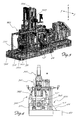
Figure 13 : shows a lateral view, from the rear, of the machine during unloading of the formed containers. - As shown and assuming solely for easier description, without a limiting meaning, a set of three reference axes extending in a longitudinal direction X-X, corresponding to the direction of feeding of the preforms and movement of the blowing assembly; transverse direction Y-Y perpendicular to the preceding direction and corresponding to the width of the machine, and vertical direction Z-Z, perpendicular to the other two directions and corresponding to the directions of opening/closing of the mould for forming the preforms, the container forming machine according to the invention comprises essentially:
- a base 1, to which
vertical columns 2 are fastened, said columns having fixed to their top end ahorizontal surface 3, as well as, in succession from upstream to downstream in the longitudinal direction X-X and in accordance with the working sequence: - an
injection unit 100 arranged on the base 1 and provided with alongitudinal injector 101; theinjection unit 100 is movable in both senses of the longitudinal direction X-X onrespective guides 102 fixed to the base; - a
station 200 for moulding thepreforms 10a, which comprises substantially:- a
corresponding base 201 to which two pairs ofvertical columns 202 are fastened, said columns passing through theupper surface 3 and extending suitably beyond the same; conveniently, thecolumns 202 are arranged at the vertices of a polygon (Figs. 1 ,3 ) with sides parallel to the longitudinal direction X-X and to the transverse direction Y-Y. Aplate 203a for supporting thefemale moulds 203 is also fastened to thebase 201, said moulds therefore being fixed; - at the top end of the
columns 202 there is fixed afurther plate 204 for supporting a cylinder 205 (Fig. 1 ), therod 205a of which is connected to aflange 206a (Figs. 2 ,6a ) carrying a plurality ofmale counter-moulds 206 coaxial with thefemale moulds 203, so that the counter-moulds 206 are able to move in both senses of the vertical direction Z-Z, so as to enter into/exit from the corresponding female moulds and therefore close/open the same simultaneously with the steps for injection/extraction of thepreforms 10a;
- a
- a blowing
station 300 comprising a blowing assembly which comprises substantially:- an
upper blowing unit 310, displaceable in both senses of the vertical direction Z-Z from an upper rest position to a lower blowing position (upon actuation of respective means 305); - a
lower unit 320 carrying the blowing mould 321. The two units, i.e.upper unit 310 andlower unit 320, form a blowing assembly displaceable in both senses of the longitudinal direction X-X on longitudinal guides fixed to the base 1 and consisting, for example of columns 301 (Figs. 2 ,4 ) or prismatic guides 1301 (Fig. 3 ).
- an
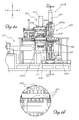
- Said movable blowing assembly is moved by an actuating unit 330 (
Fig. 3 ) comprising agearmotor 331 which drives apinion 331a meshing with alongitudinal rack 332 fixed to the base 1. - Under the control of a control and
operating unit 500 diagrammatically shown inFig. 1 , the blowing assembly is displaced in the longitudinal direction X-X within the blowingstation 300 from afirst blowing position 300A (Fig. 10a ), which is substantially adjacent to theblowing unit 200 and where it forms a first series of containers 10b, to at least onesecond blowing position 300B (Fig. 11a ) where it forms a second series of containers 10b; and a third end-of-travel position 300C (Fig. 12 ) in the longitudinal direction suitable for allowing movement of the containers 10b for subsequent unloading thereof, as will become clearer below. - In detail the
movable unit 320 carrying the blowing mould 321 comprises two half-moulds 321a,321b provided with a suitable number of blowingcavities 321c, the half-moulds being connected tomeans 340 for actuating them in both senses of the transverse direction Y-Y so as to cause symmetrical closing/opening towards/from a direction for centring the half-moulds 321a,321b with respect to the preforms to be formed. - The number of blowing cavities is smaller than the number of injection/moulding cavities in the
mould 203. - Preferably the number of blowing cavities of the two blowing half-moulds 321 is equal to a fraction of the number of injection/forming
moulds 203a of the preform injection and moulding station. - In greater detail and preferably, the number of blowing moulds 321 of the
perform blowing station 300 is a whole submultiple ≥2, preferably 2 or 3, of the number of cavities of the injection/moulding mould, the number of blowing positions (300A, 300B) of the blowing assembly corresponding to said whole submultiple. Advantageously, owing to the preferred configuration withgearmotor 331 which drives thepinion 331a meshing with alongitudinal rack 332, it is possible to vary easily, by means of the control andoperating unit 500, the number ofdifferent blowing positions - As a result, it is possible to vary the alignment, in the different blowing positions, between the blowing mould and the preforms, this being necessary in particular in the case of a change in format from containers which are symmetrical relative to the neck to containers which are asymmetrical relative to the neck, where a different cavity-preform alignment is required.
- It is convenient if the
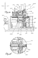
first blowing position 300A is the position closest to thepreform moulding station 200 and the disengaging position 300C is the position furthest from saidmoulding station 200, allowing an optimized working cycle. - The means 340 for actuating the two half-
moulds 321a,321b of the blowing mould 321 have an electric motor 341 which is mounted on a fixedflange 342, theshaft 341a of which is parallel to the longitudinal direction X-X and drives a kinematic chain comprising: - a
cam 343 keyed onto theshaft 341a of the electric motor 341; eachend 343a of thecam 343 is provided with a respective seat 343b for insertion of a pin 344 for hinging, respectively, a first end of afirst linkage 345 and a first end of asecond linkage 346; the other end of each linkage 345,346 being hinged by means of an associatedpin 345c,346c with afirst end 347a of arespective rocker arm 347, the other end 347b of which is hinged by means of arod 348 with the respective half-mould 321a,321b. As illustrated, the rocker arm rotates between two angular end-of-travel positions corresponding respectively to a position where the half-moulds 321 are open and a position where the two half-moulds 321a,321b are closed for blowing; rotation of therocker arm 347 occurs about a fixedcentral pivot 347c which is mounted on asupport frame 349 which also carries the guiding elements for displacement of the half-moulds 321 from the opening position to the closing position and vice versa. - As shown in
Fig. 7 , in the mould closing position, thefirst linkage 345, thesecond linkage 346 and the symmetrical cam 341 reach and stop in an aligned position, parallel to the transverse direction Y-Y, resulting in a position of the three elements such as to generate a transverse mechanical force which resists the forces inside the blowing mould, which tend instead to open said mould during the blowing step. The stability of the aligned position of the linkages is also assisted by end-of-travel means 350 which are adjustable and preferably act on the cam 341 and are arranged parallel to the vertical direction Z-Z. - Owing to this resistive mechanical force it is possible to substantially suspend full powering of the electric motor which is no longer required to oppose with its torque the internal mould opening forces; this means that, for the entire duration of blowing, the motor is supplied with a smaller current designed merely to keep the cam in position.
- Preferably, a
station 400 for unloading the formed containers 10b completes the machine. - The machine according to the invention preferably further comprises at least one pair of carriages 600 (
Fig. 5 ) for gripping and moving thepreforms 10a and the formed containers 10b from/to the various stations of the machine. - The carriages comprise means 610 for gripping and releasing the neck of the preforms and are mounted on
rails 601 which are fastened to thesurface 3 and extend along a closed polygonal path, the sides of which extend, for outward travel, in the longitudinal direction X-X between theinjection station 100 and the blowingstation 300, in the transverse direction between a front position and rear position in the blowingstation 300 and, for return travel, again along the longitudinal direction X-X, between thestation 300 for blowing and thestation 400 for unloading the formed containers 10b, and also in the transverse direction Y-Y between a rear position and a front position in the unloadingstation 400 so as to allow preparation for a new machine cycle with a displacement which brings again a carriage into alignment with the preform-forming station. The number ofmeans 610 for gripping and releasing the preforms engaged with eachcarriage 600 corresponds to the number of female cavities of the injection/moulding mould of thepreform forming station 200. - The unloading
station 400 comprises (Fig. 3 ,13 ) means 410 acting on the vertical direction for expulsion of the formed containers 10b from thecarriages 600 and means 412 with an inclined surface for guiding the falling containers 10b from thecarriages 600 towardscollection boxes 413 inside which the formed containers fall freely. With this configuration and assuming only twocarriages 600, the operating principle of the machine is as follows: - at the start of each cycle (
Figs. 6a,6b ) the machine is in the following condition:-
injection unit 100 empty and at a distance from themoulding station 200, - injection mould 203,206 open,
- blowing half-
moulds 321a,321b open, - at least one
gripping carriage 600 arranged inside themoulding station 200, - at least one
gripping carriage 600 waiting in thestation 300 for blowing thepreforms 10a;
-
- under the control of the control and operating unit 500:
- the
movable unit 320 carrying the blowing moulds 321 is moved from the third unloading position 300C to thefirst blowing position 300A adjacent to thestation 200 for moulding thepreforms 10a; - the
injector 100 is loaded with the necessary quantity of PET material, theinjector 101 is moved towards the fixedfemale moulds 203 and relative engagement is performed; - the liquid material is injected into the fixed female moulds (cavities) 203;
- closing of the injection mould is performed in the vertical direction Z-Z by lowering the
male counter-moulds 206; - once forming has occurred, the
preforms 10a are allowed to cool; - once the most suitable temperature programmed for blowing is reached the
female moulds 203 are opened, causing themale counter-moulds 206 to move back up; - the first
gripping carriage 600 moves in the longitudinal direction X-X and brings thepreforms 10a to the blowing station 300 (Figs. 9a,9b ) where the movable unit 321 carrying the blowing mould is positioned in thefirst blowing position 300A, for blowing a first series ofpreforms 10a; - the blowing mould 321 is closed in the transverse direction Y-Y and a first series of
preforms 10a are blown so that they assume the final configuration of the finished container 10b;
- the
- simultaneously
- the
second carriage 600 moves to the station for injection of thepreforms 10a; - a second quantity of material is injected into the female half-
moulds 203 for renewed injection and forming ofpreforms 10a; - a second moulding cycle is started;
- once blowing has been concluded, the
movable blowing unit 320 moves into thesecond blowing position 300B in order to form the second series of finished containers 10b supplied from the preceding moulding step; - once the second blowing cycle has been completed the
movable blowing unit 320 moves to the end position 300C, freeing thefirst carriage 600 which moves in the transverse direction Y-Y towards the rear part of the machine and from here in the longitudinal direction X-X towards the unloadingstation 400; once the station is reached it releases the containers 10b which fall onto theinclined surface 412 and from here into thecollection boxes 413; - the
movable blowing unit 320 is brought back into thefirst blowing position 300A pending arrival of thesecond carriage 600 which carries the second group ofpreforms 10a formed in themoulding station 200 and ready for blowing; - the first
gripping carriage 600 is displaced in the transverse direction Y-Y and moves from the rear part of the unloadingstation 400 to the front part and into position inside themoulding station 200.
- the
- A person skilled in the art will have the necessary skill to determine the time intervals for the cycle and for execution of the various steps as well as subdivision of the blowing mould cavities with respect to the injection mould depending on the number of female moulds of the latter and therefore the number of preforms simultaneously formed during injection and the cooling time programmed for the said preforms before they pass from the injection mould to the blowing mould. In the case of pre-blowing treatment, or where considered appropriate, the number of
carriages 600 may be increased, preferably to five carriages, optimizing the time intervals and movements, such that all the stations are as productive as possible. - It is therefore clear how, as a result of the blowing assembly displaceable in the longitudinal direction X-X and the blowing moulds realized with a number of cavities that is smaller and preferably a whole submultiple ≥2 of the number of cavities of the injection mould, it is possible to provide a machine for forming containers made of thermoplastic material with blowing of preforms obtained by means of injection in an associated station of the same machine, with a high hourly production output, resulting moreover in a significant reduction in production costs since the manufacture of small-size blowing moulds is much more economical than the manufacture of a single mould of equivalent capacity.
- In addition, by means of the blowing assembly displaceable between the various positions determined by subdividing the blowing moulds with respect to the injection mould under the control of the central control and operating unit, it is possible to vary very rapidly the number of positions of the blowing mould upon variation in the format and number of containers to be formed and therefore of the moulds, reducing the downtime of the machine.
- As shown in
Fig. 3 , it is envisaged however by way of a variant that opening/closing of the injection mould may be performed by an actuating unit comprising anelectric motor 1205, with a drive shaft parallel to the direction Y-Y and perpendicular to the vertical direction Z-Z of opening/closing of the mould, and a kinematic chain (not shown) comprising a cam and double linkage forming the subject of a co-pending patent application in the name of the same present Applicant, said cam and double linkage, during closure, being arranged aligned, parallel to the vertical direction Z-Z. - Although described in relation to an example of embodiment with a blowing-mould carrying unit movable between two different blowing positions, it is envisaged that the subdivision of the blowing moulds may also be equal to a number greater than two and, therefore, the blowing positions which the movable unit may assume may be correspondingly greater, if necessary increasing also the number of gripping and transportation carriages.
- As required, it is also possible to provide a preform treatment station arranged in an intermediate position between the injection and moulding station and the blowing station.
- Although described in connection with a number of embodiments and a number of preferred examples of embodiment of the invention, it is understood that the scope of protection of the present patent is determined solely by the claims below.
Claims (22)
- Machine for forming containers (10b) made of thermoplastic material by blow-moulding preforms (10a) obtained by means of injection/moulding within the machine, for which at least one longitudinal direction (X-X) for feeding of the preforms (10a) between the stations thereof is defined,
said machine comprising:- an injection unit (100) provided with a longitudinal injector (101);- a station (200) for moulding the preforms (10a), comprising a mould (203,206) with a predefined number of cavities for injection/moulding of preforms (10a);- a station (300) for blowing the preforms (10a), comprising a blowing assembly (310,320) for forming finished containers (10b);characterized in that
said blowing assembly (310,320) comprises a smaller number of blowing cavities (321c) than the number of injection/moulding cavities in the mould (203,206) and is displaceable in both senses of the longitudinal direction (X-X) on fixed longitudinal guides (301). - Machine according to Claim 1, characterized in that said movable blowing assembly (310,320) moves from a first blowing position (300A), where it forms a first series of containers (10b) into at least one second blowing position (300B) where it forms a second series of containers (10b); and into a third end-of-travel position (300C) in the longitudinal direction for allowing movement of the containers (10b) towards a following unloading point.
- Machine according to any one of the preceding claims, characterized in that the blowing assembly (310,320) comprises a blowing mould (321) with a number of blowing cavities (321c) equal to a whole submultiple ≥2 of the number of cavities in the mould (203,206) of the station (200) for moulding the preforms.
- Machine according to the preceding claim, characterized in that the number of blowing positions (300A,300B) of the movable blowing unit (310,320) corresponds to said whole submultiple ≥2 of the number of cavities in the mould (203,206) of the station (200) for moulding the preforms.
- Machine according to any one of the preceding claims, characterized in that said blowing assembly (310,320) is moved in the longitudinal direction (X-X) by an actuating unit (330) comprising a gearmotor (331) which drives a pinion (331a) meshing with a longitudinal rack (332).
- Machine according to any one of the preceding claims, characterized in that it comprises a control and operating unit (500) for controlling the movements and operating cycles of the machine.
- Machine according to the preceding claim, characterized in that said control and operating unit (500) is designed to vary the number of blowing positions (300A,300B) and/or the longitudinal alignment between blowing mould (321) and preforms (10a) in the blowing positions (300A, 300B).
- Machine according to any one of the preceding claims, characterized in that said blowing assembly (310,320) comprises:- an upper blowing unit (310) displaceable in both senses of the vertical direction (Z-Z) from a top rest position to a bottom blowing position; and- a lower unit (320) carrying the blowing mould (321).
- Machine according to Claim 8, characterized in that said blowing mould (321) comprises two half-moulds (321a,321b) which are movable so as to open/close in both senses of the transverse direction (Y-Y) for causing symmetrical closing/opening thereof towards/from a direction for centring of the half-moulds (321a,321b) with respect to the preforms to be formed.
- Machine according to the preceding claim, characterized in that the means (340) for actuating the two half-moulds (321a,321b) of the blowing mould (321) are moved by actuating means comprising a fixed electric motor (341), the shaft (341a) of which is parallel to the longitudinal direction (X-X) and drives a kinematic chain comprising:- a cam (343) keyed onto the shaft (341a) of the electric motor (341);- a first linkage (345) and- a second linkage (346);
a first end of each of which is hinged with a respective end (343a) of the cam (343), the other end of each linkage (345,346) being hinged with a first end (347a) of- a respective first and second rocker arm (347), the other end (347b) of which is hinged with the respective half-mould (321a,321b) by means of a rod (348). - Machine according to the preceding claim, characterized in that each rocker arm (347) rotates about a fixed central fulcrum (347c) between two angular end-of-travel positions respectively corresponding to an open position of the half-moulds (321a,321b) and a closed position of the half-moulds (321a,321b) for blowing, and vice versa.
- Machine according to Claim 10 or 11, characterized in that, in the mould closing position, the first linkage (345), the second linkage (346) and the symmetrical cam (341) reach and stop in an aligned position, parallel to the transverse direction (Y-Y).
- Machine according to any one of the preceding claims, characterized in that it comprises:- at least one pair of carriages (600) for gripping and moving the preforms (10a) and the formed containers (10b) from/to the various stations of the machine; and/or• a station (400) for unloading the formed containers (10b).
- Machine according to the preceding claim, characterized in that the carriages (600) comprise means (610) for gripping by the neck the preforms (10a) and releasing the finished containers (10b), in a number equal to said number of cavities in the mould (203,206) of the station (200) for moulding the preforms (10a).
- Machine according to Claim 13 or 14, characterized in that the carriages (600) are mounted on fixed rails (601) extending along a closed polygonal path, the sides of which extend:- for outward travel in the longitudinal direction (X-X) between the injection station (100) and the blowing station (300) and between the station (300) for blowing and the station (400) for unloading the formed containers (10b), in the transverse direction (Y-Y) between a front position and a rear position in the blowing station (300) and,- in the longitudinal direction (X-X) between a rear position and a front position, where they are aligned in the transverse direction (Y-Y) with the station (200) for forming the preforms, but upstream of the latter in the longitudinal direction (X-X).
- Machine according to Claim 14, characterized in that, during the moulding and/or blowing step, the carriages (600) are arranged respectively between the male injection counter-moulds (206) and the female injection moulds and/or between the upper blowing unit (310) and the lower unit (320) carrying the blowing mould (321).
- Machine according to any one of Claims 13 to 16, characterized in that the position of the carriage (600) in the blowing station (300) is fixed.
- Machine according to any one of the preceding claims, characterized in that it comprises a preform treatment station arranged in an intermediate position between the injection/moulding station (200) and the blowing station (300).
- Method for forming containers (10b) made of thermoplastic material by blow-moulding preforms (10a) obtained by means of injection/moulding, using a single machine, there being defined a longitudinal direction (X-X) of feeding of the preforms (10a) inside the machine, said method comprising the steps of:- injecting thermoplastic material into a mould (203,206) of a moulding station (200) with a predefined number of cavities for injection/moulding of preforms (10a);- moulding the preforms (10a) inside the injection/moulding cavities of the mould (203,206);- blowing the preforms (10a) in a blowing station (300) comprising a blowing assembly (310,320) for forming finished containers (10b);
characterized in that
during the blowing step said blowing assembly (310,320) moves in both senses of the longitudinal direction (X-X) and in that it is realized with a smaller number of blowing cavities (321c) than the number of injection/blowing cavities in the mould (203, 206). - Method according to the preceding claim, characterized in that, during the blowing step, the displacement of said movable blowing assembly (310,320) occurs between a first blowing position (300A), where a first series of containers (10b) is formed, at least one second blowing position (300B) in which a further series of containers (10b) is formed, and a third end-of-travel position (300C) in the longitudinal direction (X-X) for allowing movement of the containers (10b) towards the following unloading point.
- Machine according to the preceding claim, characterized in that in each blowing position (300A,300B) of the blowing step, a number of containers equal (10b) to a whole submultiple ≥2 of the number of cavities in the mould (203,206) of the station (200) for moulding the preforms (10a) are blown.
- Method according to the preceding claim, characterized in that the number of blowing positions (300A,330B) of the blowing step corresponds to said whole submultiple ≥2 of the number of cavities in the mould (203,206) of the station (200) for moulding the preforms.
Applications Claiming Priority (1)
| Application Number | Priority Date | Filing Date | Title |
|---|---|---|---|
| IT001557A ITMI20131557A1 (en) | 2013-09-20 | 2013-09-20 | MACHINE FOR THE CONSTRUCTION OF CONTAINERS IN THERMOPLASTIC MATERIAL |
Publications (2)
| Publication Number | Publication Date |
|---|---|
| EP2851176A1 true EP2851176A1 (en) | 2015-03-25 |
| EP2851176B1 EP2851176B1 (en) | 2016-07-27 |
Family
ID=49683868
Family Applications (1)
| Application Number | Title | Priority Date | Filing Date |
|---|---|---|---|
| EP14184220.3A Active EP2851176B1 (en) | 2013-09-20 | 2014-09-10 | Machine for forming containers made of thermoplastic material |
Country Status (11)
| Country | Link |
|---|---|
| US (1) | US9962879B2 (en) |
| EP (1) | EP2851176B1 (en) |
| JP (1) | JP6012683B2 (en) |
| BR (1) | BR102014023343B1 (en) |
| CA (1) | CA2863854C (en) |
| DK (1) | DK2851176T3 (en) |
| ES (1) | ES2590729T3 (en) |
| HU (1) | HUE030766T2 (en) |
| IT (1) | ITMI20131557A1 (en) |
| PL (1) | PL2851176T3 (en) |
| PT (1) | PT2851176T (en) |
Cited By (1)
| Publication number | Priority date | Publication date | Assignee | Title |
|---|---|---|---|---|
| CN109318465A (en) * | 2018-10-08 | 2019-02-12 | 符经厚 | A kind of plastic bottle Preparation equipment |
Families Citing this family (4)
| Publication number | Priority date | Publication date | Assignee | Title |
|---|---|---|---|---|
| JP6552890B2 (en) * | 2015-06-30 | 2019-07-31 | 株式会社青木固研究所 | Method of forming container by injection stretch blow molding machine |
| ITUA20164132A1 (en) * | 2016-06-06 | 2017-12-06 | Bva | MACHINE FOR MOLDING AND BLOWING OF CONTAINERS OBTAINED FROM CORRESPONDING PREFORMATIONS OF A THERMOPLASTIC MATERIAL. |
| IT201600128349A1 (en) * | 2016-12-19 | 2018-06-19 | True Keg S R L | PREFORMING STIROSOFFICING MACHINE FOR THE CONSTRUCTION OF CONTAINERS INTENDED FOR THE MAKING OF DRUMS TO LOSE FOR FOOD LIQUIDS |
| WO2023003022A1 (en) * | 2021-07-21 | 2023-01-26 | 日精エー・エス・ビー機械株式会社 | Resin container production device and method for producing resin container |
Citations (3)
| Publication number | Priority date | Publication date | Assignee | Title |
|---|---|---|---|---|
| US4470796A (en) * | 1980-06-23 | 1984-09-11 | Van Dorn Company | Apparatus for molding hollow plastic articles |
| US4824359A (en) * | 1986-12-15 | 1989-04-25 | Hoover Universal, Inc. | Dual injection mold preform transfer assembly |
| EP1153727A2 (en) * | 2000-04-11 | 2001-11-14 | Magic MP S.p.A. | Machine for the production of preforms for hollow plastic containers |
Family Cites Families (5)
| Publication number | Priority date | Publication date | Assignee | Title |
|---|---|---|---|---|
| JPH0647272B2 (en) * | 1989-11-17 | 1994-06-22 | 日精エー・エス・ビー機械株式会社 | Injection stretch blow molding method |
| JPH06134845A (en) * | 1992-10-28 | 1994-05-17 | Nissei Asb Mach Co Ltd | Injection stretching blow molding machine |
| JP3158102B2 (en) * | 1994-09-16 | 2001-04-23 | 日精エー・エス・ビー機械株式会社 | Injection stretch blow molding method |
| ITMI20012230A1 (en) * | 2001-10-24 | 2003-04-24 | Magic Mp Spa | BLOWER FORMING MACHINE FOR PLASTIC CONTAINERS EQUIPPED WITH ELECTRIC TYPE DRIVE DEVICES |
| JP4791182B2 (en) * | 2005-12-29 | 2011-10-12 | 日精エー・エス・ビー機械株式会社 | Injection blow molding machine |
-
2013
- 2013-09-20 IT IT001557A patent/ITMI20131557A1/en unknown
-
2014
- 2014-09-10 HU HUE14184220A patent/HUE030766T2/en unknown
- 2014-09-10 PL PL14184220T patent/PL2851176T3/en unknown
- 2014-09-10 DK DK14184220.3T patent/DK2851176T3/en active
- 2014-09-10 EP EP14184220.3A patent/EP2851176B1/en active Active
- 2014-09-10 ES ES14184220.3T patent/ES2590729T3/en active Active
- 2014-09-10 PT PT141842203T patent/PT2851176T/en unknown
- 2014-09-16 JP JP2014187248A patent/JP6012683B2/en active Active
- 2014-09-16 CA CA2863854A patent/CA2863854C/en active Active
- 2014-09-19 US US14/491,021 patent/US9962879B2/en active Active
- 2014-09-19 BR BR102014023343-1A patent/BR102014023343B1/en not_active IP Right Cessation
Patent Citations (3)
| Publication number | Priority date | Publication date | Assignee | Title |
|---|---|---|---|---|
| US4470796A (en) * | 1980-06-23 | 1984-09-11 | Van Dorn Company | Apparatus for molding hollow plastic articles |
| US4824359A (en) * | 1986-12-15 | 1989-04-25 | Hoover Universal, Inc. | Dual injection mold preform transfer assembly |
| EP1153727A2 (en) * | 2000-04-11 | 2001-11-14 | Magic MP S.p.A. | Machine for the production of preforms for hollow plastic containers |
Cited By (2)
| Publication number | Priority date | Publication date | Assignee | Title |
|---|---|---|---|---|
| CN109318465A (en) * | 2018-10-08 | 2019-02-12 | 符经厚 | A kind of plastic bottle Preparation equipment |
| CN109318465B (en) * | 2018-10-08 | 2020-08-04 | 泰安锦泰塑料制品有限公司 | Plastic bottle preparation equipment |
Also Published As
| Publication number | Publication date |
|---|---|
| CA2863854C (en) | 2018-08-21 |
| BR102014023343A2 (en) | 2015-09-08 |
| US20150084243A1 (en) | 2015-03-26 |
| HUE030766T2 (en) | 2017-05-29 |
| JP6012683B2 (en) | 2016-10-25 |
| BR102014023343B1 (en) | 2021-02-02 |
| PL2851176T3 (en) | 2017-02-28 |
| PT2851176T (en) | 2016-09-08 |
| EP2851176B1 (en) | 2016-07-27 |
| US9962879B2 (en) | 2018-05-08 |
| ES2590729T3 (en) | 2016-11-23 |
| ITMI20131557A1 (en) | 2015-03-21 |
| DK2851176T3 (en) | 2016-11-14 |
| CA2863854A1 (en) | 2015-03-20 |
| JP2015077795A (en) | 2015-04-23 |
Similar Documents
| Publication | Publication Date | Title |
|---|---|---|
| EP2851176B1 (en) | Machine for forming containers made of thermoplastic material | |
| EP0001626B1 (en) | Injection blow molding apparatus method | |
| US20210394420A1 (en) | Blow molding device and blow molding method | |
| US9550321B2 (en) | Molded product delivery apparatus and blow molding machine | |
| EP0162458B1 (en) | Temperature control blow molding equipment in injection stretch blow molding machine | |
| JP6751739B2 (en) | Biaxial stretch blow molding equipment | |
| EP3858581A1 (en) | Blow molding machine and method for controlling blow molding machine | |
| CN115519771A (en) | Continuous blow molding machine, preform, system and process | |
| KR101543389B1 (en) | Blow mold unit and blow-molding machine using same | |
| AU2018204788B2 (en) | Blow moulding machine, preforms, system and process | |
| US6217819B1 (en) | Universal single-row and multi-row insert stretch blow molding method and apparatus therefor | |
| US20010038866A1 (en) | Machine for the production of preforms for hollow plastic containers | |
| WO2003078122A2 (en) | Single-row and multi-row stretch blow- molding method and apparatus therefor | |
| JP4791182B2 (en) | Injection blow molding machine | |
| JP4969438B2 (en) | Molding of plastic products | |
| EP1306194A2 (en) | Machine for blow moulding containers from cold parisons with step for conditioning said parisons. | |
| KR20240046601A (en) | Continuous blow moulding machine, preforms, system and process | |
| JPH0649330B2 (en) | Injection stretch blow molding machine |
Legal Events
| Date | Code | Title | Description |
|---|---|---|---|
| PUAI | Public reference made under article 153(3) epc to a published international application that has entered the european phase |
Free format text: ORIGINAL CODE: 0009012 |
|
| 17P | Request for examination filed |
Effective date: 20140910 |
|
| AK | Designated contracting states |
Kind code of ref document: A1 Designated state(s): AL AT BE BG CH CY CZ DE DK EE ES FI FR GB GR HR HU IE IS IT LI LT LU LV MC MK MT NL NO PL PT RO RS SE SI SK SM TR |
|
| AX | Request for extension of the european patent |
Extension state: BA ME |
|
| R17P | Request for examination filed (corrected) |
Effective date: 20150908 |
|
| RBV | Designated contracting states (corrected) |
Designated state(s): AL AT BE BG CH CY CZ DE DK EE ES FI FR GB GR HR HU IE IS IT LI LT LU LV MC MK MT NL NO PL PT RO RS SE SI SK SM TR |
|
| REG | Reference to a national code |
Ref country code: DE Ref legal event code: R079 Ref document number: 602014002861 Country of ref document: DE Free format text: PREVIOUS MAIN CLASS: B29C0049060000 Ipc: B29C0049020000 |
|
| GRAP | Despatch of communication of intention to grant a patent |
Free format text: ORIGINAL CODE: EPIDOSNIGR1 |
|
| RIC1 | Information provided on ipc code assigned before grant |
Ipc: B29C 49/06 20060101ALI20160205BHEP Ipc: B29C 49/02 20060101AFI20160205BHEP Ipc: B29C 49/32 20060101ALI20160205BHEP Ipc: B29C 49/28 20060101ALI20160205BHEP Ipc: B29C 49/56 20060101ALI20160205BHEP Ipc: B29L 31/00 20060101ALI20160205BHEP |
|
| INTG | Intention to grant announced |
Effective date: 20160225 |
|
| GRAS | Grant fee paid |
Free format text: ORIGINAL CODE: EPIDOSNIGR3 |
|
| GRAA | (expected) grant |
Free format text: ORIGINAL CODE: 0009210 |
|
| AK | Designated contracting states |
Kind code of ref document: B1 Designated state(s): AL AT BE BG CH CY CZ DE DK EE ES FI FR GB GR HR HU IE IS IT LI LT LU LV MC MK MT NL NO PL PT RO RS SE SI SK SM TR |
|
| REG | Reference to a national code |
Ref country code: GB Ref legal event code: FG4D |
|
| REG | Reference to a national code |
Ref country code: CH Ref legal event code: EP |
|
| REG | Reference to a national code |
Ref country code: CH Ref legal event code: NV Representative=s name: DR. LUSUARDI AG, CH Ref country code: AT Ref legal event code: REF Ref document number: 815420 Country of ref document: AT Kind code of ref document: T Effective date: 20160815 |
|
| REG | Reference to a national code |
Ref country code: IE Ref legal event code: FG4D |
|
| REG | Reference to a national code |
Ref country code: DE Ref legal event code: R096 Ref document number: 602014002861 Country of ref document: DE Ref country code: PT Ref legal event code: SC4A Ref document number: 2851176 Country of ref document: PT Date of ref document: 20160908 Kind code of ref document: T Free format text: AVAILABILITY OF NATIONAL TRANSLATION Effective date: 20160901 |
|
| REG | Reference to a national code |
Ref country code: FR Ref legal event code: PLFP Year of fee payment: 3 |
|
| REG | Reference to a national code |
Ref country code: SE Ref legal event code: TRGR |
|
| REG | Reference to a national code |
Ref country code: DK Ref legal event code: T3 Effective date: 20161111 |
|
| REG | Reference to a national code |
Ref country code: ES Ref legal event code: FG2A Ref document number: 2590729 Country of ref document: ES Kind code of ref document: T3 Effective date: 20161123 |
|
| REG | Reference to a national code |
Ref country code: LT Ref legal event code: MG4D |
|
| REG | Reference to a national code |
Ref country code: NL Ref legal event code: MP Effective date: 20160727 |
|
| PG25 | Lapsed in a contracting state [announced via postgrant information from national office to epo] |
Ref country code: FI Free format text: LAPSE BECAUSE OF FAILURE TO SUBMIT A TRANSLATION OF THE DESCRIPTION OR TO PAY THE FEE WITHIN THE PRESCRIBED TIME-LIMIT Effective date: 20160727 Ref country code: RS Free format text: LAPSE BECAUSE OF FAILURE TO SUBMIT A TRANSLATION OF THE DESCRIPTION OR TO PAY THE FEE WITHIN THE PRESCRIBED TIME-LIMIT Effective date: 20160727 Ref country code: NO Free format text: LAPSE BECAUSE OF FAILURE TO SUBMIT A TRANSLATION OF THE DESCRIPTION OR TO PAY THE FEE WITHIN THE PRESCRIBED TIME-LIMIT Effective date: 20161027 Ref country code: IS Free format text: LAPSE BECAUSE OF FAILURE TO SUBMIT A TRANSLATION OF THE DESCRIPTION OR TO PAY THE FEE WITHIN THE PRESCRIBED TIME-LIMIT Effective date: 20161127 Ref country code: HR Free format text: LAPSE BECAUSE OF FAILURE TO SUBMIT A TRANSLATION OF THE DESCRIPTION OR TO PAY THE FEE WITHIN THE PRESCRIBED TIME-LIMIT Effective date: 20160727 Ref country code: LT Free format text: LAPSE BECAUSE OF FAILURE TO SUBMIT A TRANSLATION OF THE DESCRIPTION OR TO PAY THE FEE WITHIN THE PRESCRIBED TIME-LIMIT Effective date: 20160727 Ref country code: NL Free format text: LAPSE BECAUSE OF FAILURE TO SUBMIT A TRANSLATION OF THE DESCRIPTION OR TO PAY THE FEE WITHIN THE PRESCRIBED TIME-LIMIT Effective date: 20160727 |
|
| REG | Reference to a national code |
Ref country code: SK Ref legal event code: T3 Ref document number: E 22434 Country of ref document: SK |
|
| PG25 | Lapsed in a contracting state [announced via postgrant information from national office to epo] |
Ref country code: LV Free format text: LAPSE BECAUSE OF FAILURE TO SUBMIT A TRANSLATION OF THE DESCRIPTION OR TO PAY THE FEE WITHIN THE PRESCRIBED TIME-LIMIT Effective date: 20160727 Ref country code: BE Free format text: LAPSE BECAUSE OF NON-PAYMENT OF DUE FEES Effective date: 20160727 |
|
| REG | Reference to a national code |
Ref country code: GR Ref legal event code: EP Ref document number: 20160402637 Country of ref document: GR Effective date: 20170130 |
|
| PG25 | Lapsed in a contracting state [announced via postgrant information from national office to epo] |
Ref country code: MC Free format text: LAPSE BECAUSE OF FAILURE TO SUBMIT A TRANSLATION OF THE DESCRIPTION OR TO PAY THE FEE WITHIN THE PRESCRIBED TIME-LIMIT Effective date: 20160727 Ref country code: RO Free format text: LAPSE BECAUSE OF FAILURE TO SUBMIT A TRANSLATION OF THE DESCRIPTION OR TO PAY THE FEE WITHIN THE PRESCRIBED TIME-LIMIT Effective date: 20160727 Ref country code: EE Free format text: LAPSE BECAUSE OF FAILURE TO SUBMIT A TRANSLATION OF THE DESCRIPTION OR TO PAY THE FEE WITHIN THE PRESCRIBED TIME-LIMIT Effective date: 20160727 |
|
| REG | Reference to a national code |
Ref country code: DE Ref legal event code: R097 Ref document number: 602014002861 Country of ref document: DE |
|
| REG | Reference to a national code |
Ref country code: HU Ref legal event code: AG4A Ref document number: E030766 Country of ref document: HU |
|
| PG25 | Lapsed in a contracting state [announced via postgrant information from national office to epo] |
Ref country code: BG Free format text: LAPSE BECAUSE OF FAILURE TO SUBMIT A TRANSLATION OF THE DESCRIPTION OR TO PAY THE FEE WITHIN THE PRESCRIBED TIME-LIMIT Effective date: 20161027 Ref country code: SM Free format text: LAPSE BECAUSE OF FAILURE TO SUBMIT A TRANSLATION OF THE DESCRIPTION OR TO PAY THE FEE WITHIN THE PRESCRIBED TIME-LIMIT Effective date: 20160727 |
|
| PLBE | No opposition filed within time limit |
Free format text: ORIGINAL CODE: 0009261 |
|
| STAA | Information on the status of an ep patent application or granted ep patent |
Free format text: STATUS: NO OPPOSITION FILED WITHIN TIME LIMIT |
|
| REG | Reference to a national code |
Ref country code: IE Ref legal event code: MM4A |
|
| 26N | No opposition filed |
Effective date: 20170502 |
|
| PG25 | Lapsed in a contracting state [announced via postgrant information from national office to epo] |
Ref country code: IE Free format text: LAPSE BECAUSE OF NON-PAYMENT OF DUE FEES Effective date: 20160910 |
|
| PG25 | Lapsed in a contracting state [announced via postgrant information from national office to epo] |
Ref country code: LU Free format text: LAPSE BECAUSE OF NON-PAYMENT OF DUE FEES Effective date: 20160910 Ref country code: SI Free format text: LAPSE BECAUSE OF FAILURE TO SUBMIT A TRANSLATION OF THE DESCRIPTION OR TO PAY THE FEE WITHIN THE PRESCRIBED TIME-LIMIT Effective date: 20160727 |
|
| REG | Reference to a national code |
Ref country code: FR Ref legal event code: PLFP Year of fee payment: 4 |
|
| PG25 | Lapsed in a contracting state [announced via postgrant information from national office to epo] |
Ref country code: MT Free format text: LAPSE BECAUSE OF NON-PAYMENT OF DUE FEES Effective date: 20160930 Ref country code: CY Free format text: LAPSE BECAUSE OF FAILURE TO SUBMIT A TRANSLATION OF THE DESCRIPTION OR TO PAY THE FEE WITHIN THE PRESCRIBED TIME-LIMIT Effective date: 20160727 Ref country code: MK Free format text: LAPSE BECAUSE OF FAILURE TO SUBMIT A TRANSLATION OF THE DESCRIPTION OR TO PAY THE FEE WITHIN THE PRESCRIBED TIME-LIMIT Effective date: 20160727 |
|
| REG | Reference to a national code |
Ref country code: FR Ref legal event code: PLFP Year of fee payment: 5 |
|
| PG25 | Lapsed in a contracting state [announced via postgrant information from national office to epo] |
Ref country code: AL Free format text: LAPSE BECAUSE OF FAILURE TO SUBMIT A TRANSLATION OF THE DESCRIPTION OR TO PAY THE FEE WITHIN THE PRESCRIBED TIME-LIMIT Effective date: 20160727 Ref country code: TR Free format text: LAPSE BECAUSE OF FAILURE TO SUBMIT A TRANSLATION OF THE DESCRIPTION OR TO PAY THE FEE WITHIN THE PRESCRIBED TIME-LIMIT Effective date: 20160727 |
|
| REG | Reference to a national code |
Ref country code: AT Ref legal event code: UEP Ref document number: 815420 Country of ref document: AT Kind code of ref document: T Effective date: 20160727 |
|
| P01 | Opt-out of the competence of the unified patent court (upc) registered |
Effective date: 20230323 |
|
| PGFP | Annual fee paid to national office [announced via postgrant information from national office to epo] |
Ref country code: GB Payment date: 20230919 Year of fee payment: 10 Ref country code: CZ Payment date: 20230904 Year of fee payment: 10 Ref country code: AT Payment date: 20230921 Year of fee payment: 10 |
|
| PGFP | Annual fee paid to national office [announced via postgrant information from national office to epo] |
Ref country code: SK Payment date: 20230905 Year of fee payment: 10 Ref country code: SE Payment date: 20230922 Year of fee payment: 10 Ref country code: PT Payment date: 20230904 Year of fee payment: 10 Ref country code: PL Payment date: 20230904 Year of fee payment: 10 Ref country code: HU Payment date: 20230905 Year of fee payment: 10 Ref country code: GR Payment date: 20230921 Year of fee payment: 10 Ref country code: FR Payment date: 20230919 Year of fee payment: 10 Ref country code: DK Payment date: 20230921 Year of fee payment: 10 Ref country code: DE Payment date: 20230921 Year of fee payment: 10 |
|
| PGFP | Annual fee paid to national office [announced via postgrant information from national office to epo] |
Ref country code: ES Payment date: 20231002 Year of fee payment: 10 |
|
| PGFP | Annual fee paid to national office [announced via postgrant information from national office to epo] |
Ref country code: IT Payment date: 20230925 Year of fee payment: 10 Ref country code: CH Payment date: 20231001 Year of fee payment: 10 |