EP2851133A1 - Fluid dispenser and method for simultaneously dispensing fluids from multiple cartridges - Google Patents
Fluid dispenser and method for simultaneously dispensing fluids from multiple cartridges Download PDFInfo
- Publication number
- EP2851133A1 EP2851133A1 EP14185437.2A EP14185437A EP2851133A1 EP 2851133 A1 EP2851133 A1 EP 2851133A1 EP 14185437 A EP14185437 A EP 14185437A EP 2851133 A1 EP2851133 A1 EP 2851133A1
- Authority
- EP
- European Patent Office
- Prior art keywords
- fluid
- cartridges
- dispensing
- fluids
- cartridge
- Prior art date
- Legal status (The legal status is an assumption and is not a legal conclusion. Google has not performed a legal analysis and makes no representation as to the accuracy of the status listed.)
- Granted
Links
- 239000012530 fluid Substances 0.000 title claims abstract description 99
- 238000000034 method Methods 0.000 title claims abstract description 10
- 230000007246 mechanism Effects 0.000 claims abstract description 16
- 238000004140 cleaning Methods 0.000 claims abstract description 9
- 238000004891 communication Methods 0.000 claims description 4
- 230000008878 coupling Effects 0.000 description 3
- 238000010168 coupling process Methods 0.000 description 3
- 238000005859 coupling reaction Methods 0.000 description 3
- 239000000565 sealant Substances 0.000 description 3
- 239000004593 Epoxy Substances 0.000 description 2
- 125000003700 epoxy group Chemical group 0.000 description 2
- 238000012423 maintenance Methods 0.000 description 2
- 239000000463 material Substances 0.000 description 2
- 229920000647 polyepoxide Polymers 0.000 description 2
- 238000007789 sealing Methods 0.000 description 2
- DHKHKXVYLBGOIT-UHFFFAOYSA-N acetaldehyde Diethyl Acetal Natural products CCOC(C)OCC DHKHKXVYLBGOIT-UHFFFAOYSA-N 0.000 description 1
- 125000002777 acetyl group Chemical group [H]C([H])([H])C(*)=O 0.000 description 1
- 239000000853 adhesive Substances 0.000 description 1
- 230000001070 adhesive effect Effects 0.000 description 1
- 239000000356 contaminant Substances 0.000 description 1
- 239000000428 dust Substances 0.000 description 1
- 230000007613 environmental effect Effects 0.000 description 1
- 239000003292 glue Substances 0.000 description 1
- 238000012986 modification Methods 0.000 description 1
- 230000004048 modification Effects 0.000 description 1
- 230000008569 process Effects 0.000 description 1
- 238000012552 review Methods 0.000 description 1
- 125000006850 spacer group Chemical class 0.000 description 1
Images

Classifications
-
- B—PERFORMING OPERATIONS; TRANSPORTING
- B05—SPRAYING OR ATOMISING IN GENERAL; APPLYING FLUENT MATERIALS TO SURFACES, IN GENERAL
- B05C—APPARATUS FOR APPLYING FLUENT MATERIALS TO SURFACES, IN GENERAL
- B05C17/00—Hand tools or apparatus using hand held tools, for applying liquids or other fluent materials to, for spreading applied liquids or other fluent materials on, or for partially removing applied liquids or other fluent materials from, surfaces
- B05C17/005—Hand tools or apparatus using hand held tools, for applying liquids or other fluent materials to, for spreading applied liquids or other fluent materials on, or for partially removing applied liquids or other fluent materials from, surfaces for discharging material from a reservoir or container located in or on the hand tool through an outlet orifice by pressure without using surface contacting members like pads or brushes
- B05C17/00553—Hand tools or apparatus using hand held tools, for applying liquids or other fluent materials to, for spreading applied liquids or other fluent materials on, or for partially removing applied liquids or other fluent materials from, surfaces for discharging material from a reservoir or container located in or on the hand tool through an outlet orifice by pressure without using surface contacting members like pads or brushes with means allowing the stock of material to consist of at least two different components
-
- B—PERFORMING OPERATIONS; TRANSPORTING
- B05—SPRAYING OR ATOMISING IN GENERAL; APPLYING FLUENT MATERIALS TO SURFACES, IN GENERAL
- B05C—APPARATUS FOR APPLYING FLUENT MATERIALS TO SURFACES, IN GENERAL
- B05C17/00—Hand tools or apparatus using hand held tools, for applying liquids or other fluent materials to, for spreading applied liquids or other fluent materials on, or for partially removing applied liquids or other fluent materials from, surfaces
- B05C17/005—Hand tools or apparatus using hand held tools, for applying liquids or other fluent materials to, for spreading applied liquids or other fluent materials on, or for partially removing applied liquids or other fluent materials from, surfaces for discharging material from a reservoir or container located in or on the hand tool through an outlet orifice by pressure without using surface contacting members like pads or brushes
- B05C17/00596—The liquid or other fluent material being supplied from a rigid removable cartridge having no active dispensing means, i.e. the cartridge requiring cooperation with means of the handtool to expel the material
-
- B—PERFORMING OPERATIONS; TRANSPORTING
- B05—SPRAYING OR ATOMISING IN GENERAL; APPLYING FLUENT MATERIALS TO SURFACES, IN GENERAL
- B05C—APPARATUS FOR APPLYING FLUENT MATERIALS TO SURFACES, IN GENERAL
- B05C17/00—Hand tools or apparatus using hand held tools, for applying liquids or other fluent materials to, for spreading applied liquids or other fluent materials on, or for partially removing applied liquids or other fluent materials from, surfaces
- B05C17/005—Hand tools or apparatus using hand held tools, for applying liquids or other fluent materials to, for spreading applied liquids or other fluent materials on, or for partially removing applied liquids or other fluent materials from, surfaces for discharging material from a reservoir or container located in or on the hand tool through an outlet orifice by pressure without using surface contacting members like pads or brushes
- B05C17/01—Hand tools or apparatus using hand held tools, for applying liquids or other fluent materials to, for spreading applied liquids or other fluent materials on, or for partially removing applied liquids or other fluent materials from, surfaces for discharging material from a reservoir or container located in or on the hand tool through an outlet orifice by pressure without using surface contacting members like pads or brushes with manually mechanically or electrically actuated piston or the like
- B05C17/0103—Hand tools or apparatus using hand held tools, for applying liquids or other fluent materials to, for spreading applied liquids or other fluent materials on, or for partially removing applied liquids or other fluent materials from, surfaces for discharging material from a reservoir or container located in or on the hand tool through an outlet orifice by pressure without using surface contacting members like pads or brushes with manually mechanically or electrically actuated piston or the like with electrically actuated piston or the like
-
- B—PERFORMING OPERATIONS; TRANSPORTING
- B05—SPRAYING OR ATOMISING IN GENERAL; APPLYING FLUENT MATERIALS TO SURFACES, IN GENERAL
- B05B—SPRAYING APPARATUS; ATOMISING APPARATUS; NOZZLES
- B05B15/00—Details of spraying plant or spraying apparatus not otherwise provided for; Accessories
- B05B15/50—Arrangements for cleaning; Arrangements for preventing deposits, drying-out or blockage; Arrangements for detecting improper discharge caused by the presence of foreign matter
Definitions
- the present invention generally relates to cartridge dispensing devices in which at least two cartridges simultaneously dispense one or more fluids from the cartridges.
- viscous fluids such as glues, sealants, epoxies, etc.
- these fluids are provided in the form of pre-proportioned and mixed, single use cartridges.
- the cartridges of fluid may be frozen.
- pneumatically operated caulking guns used by technicians who then manually apply the fluid to a product or workpiece. This is a time consuming and labor intensive process.
- the apparatus typically used for these applications may be difficult to use and maintain.
- the invention provides a fluid dispenser for simultaneously dispensing fluids from first and second cartridges. It will be appreciated that the invention covers dispensers that are configured to simultaneously dispense from more than first and second cartridges, i.e., three or more cartridges.
- the fluid dispenser includes a base structure and a cartridge holding assembly mounted to the base structure.
- the cartridge holding assembly includes first and second cartridge holders.
- a linear drive mechanism is mounted to the base structure.
- First and second drive pistons are operatively connected to the linear drive mechanism and movable into respective first and second cartridges when the first and second cartridges are held in the first and second cartridge holders. In this manner fluids are simultaneously dispensed from the first and second cartridges.
- the first and second cartridge holders further comprise tubular members carried on the cartridge holding assembly, and also removable for maintenance and/or replacement.
- the cartridge holding assembly further comprises a dispensing portion including respective first and second fluid passages in fluid communication with the respective first and second cartridge holders.
- the first and second fluid passages receive the fluids from the first and second cartridges as the first and second drive pistons are driven into the first and second cartridges.
- An outlet passage communicates with the first and second fluid passages. The outlet passage dispenses the fluids from the first and second fluid passages.
- the dispensing portion further comprises first and second sections removably secured together, each section having lengthwise portions of the first and second passages therein for allowing cleaning of the lengthwise portions upon removal of the first section from the second section.
- the dispensing portion is removably secured to the first and second cartridge holders, preferably by at least one quick connector.
- a plurality of clasps secures the dispensing portion to a remaining portion of the cartridge holding assembly.
- a fluid dispenser comprises a base structure and a cartridge holding assembly mounted to the base structure and including first and second cartridge holders.
- a linear drive mechanism is mounted to the base structure.
- First and second drive pistons are operatively connected to the linear drive mechanism.
- the linear drive mechanism drives the first and second drive pistons into respective first and second cartridges when the first and second cartridges are held in the first and second cartridge holders such that fluids are dispensed from the first and second cartridges.
- a dispensing portion includes respective first and second fluid passages in fluid communication with the respective first and second cartridge holders for receiving fluids from the first and second cartridges as the first and second drive pistons are moved into the first and second cartridges.
- the dispensing portion further comprises first and second sections removably secured together. Each section includes lengthwise portions of the first and second passages therein for allowing cleaning of the lengthwise portions upon removal of the first section from the second section.
- the invention provides a method of operating a fluid dispenser for simultaneously dispensing fluids from first and second cartridges.
- First and second cartridges are then loaded into respective first and second cartridge holders of the cartridge holding assembly.
- First and second pistons are then driven into the first and second cartridges to dispense fluids from the first and second cartridges.
- the invention provides a method of dispensing fluids and cleaning residual fluid from a fluid dispenser adapted to simultaneously dispense the fluids from first and second cartridges.
- This method generally includes loading first and second cartridges into respective first and second cartridge holders of the cartridge holding assembly.
- First and second pistons are respectively driven into the first and second cartridges to force fluids from the first and second cartridges. Fluid is thereby directed from the first and second cartridges respectively into first and second fluid passages of a dispensing portion.
- the fluids are dispensed from the first and second fluid passages, such as, by being directed through an outlet passage that combines the fluids.
- a first section of the dispensing portion is removed from a second section of the dispensing portion to expose respective lengthwise portions of the first and second fluid passages in the first and second sections. The lengthwise portions are then cleaned of residual fluid.
- Figs. 1 and 2 respectively illustrate a fluid dispenser 10 in operating and service positions.
- the fluid dispenser 10 includes a base structure 12 including a base plate 14 and a cartridge holding assembly 16 is mounted to the base structure 12.
- the connection between the cartridge holding assembly 16 and base structure 12 is pivotal and includes pivot mounts 18, 19 connected to the base plate 14, and two pivots 20, 21 ( Fig. 4 ).
- a fluid cylinder 22, such as an air cylinder, is provided and includes an actuating rod 24 coupled to a pivoting mechanism 26.
- the rod 24 is extended as shown in Fig. 1
- the cartridge holding assembly 16 is held in an operating position.
- the rod 24 is actuated to a retracted position as shown in Fig.
- the cartridge holding assembly 16 includes first and second cartridge holders 32, 34, including tubular members 36, 38 which, more specifically, comprise hollow cylindrical members having respective mounting elements 40, 42. It will be appreciated that the cartridge holding assembly 16 may be modified to hold more than two cartridges, and the invention is not limited to dispensing simultaneously from only two cartridges but, rather, encompasses dispensing from more than two cartridges.
- a linear drive mechanism 44 is mounted to the base structure 12. An electrical connector 46 is provided for supplying power to the electric drive motor (not shown) associated with the linear drive mechanism 44. A magnetic brake 47 is provided for stopping the linear drive mechanism 44 in the event that power is lost.
- First and second drive pistons 50, 52 are operatively connected to the linear drive mechanism 44. More specifically, the pistons 50, 52 extend from rods 54, 56 that are guided by respective linear bearings 58, 60 along linear paths indicated by arrows 62, 64.
- a bracket 66 ( Fig. 1 ) at an end opposite to the drive pistons 50, 52 couples the rods 54, 56 together and also couples the rods 54, 56 for movement with the linear drive mechanism 44 via a central rod 70.
- a bellows 72 protects the internal components of the linear drive mechanism 44 from any environmental contaminants such as dirt or dust.
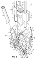
- First and second fluid cartridges 74, 76 are inserted into the tubular members 36, 38 of the first and second cartridge holders 32, 34 as schematically illustrated in Fig. 2 .
- the cartridges 74, 76 may contain the same fluid, for example, if greater productivity is desired than is possible with a single cartridge dispenser. Or, the cartridges 74, 76 may contain different fluids if mixing of two different fluids is desired. In any case, the fluid may comprise any desired fluid such as sealant, adhesive, epoxies or other fluids depending on the application needs.
- a bracket or plate 80 is rigidly coupled to the base plate 14 and includes a slot 82 through which one of the cylindrical cartridge holder tubes 38 extends. The ends of this slot 82 act as stops to ensure that the cartridge holders 32,34 are positioned accurately in both positions, i.e., the operating position and the service position shown respectively in Figs. 1 and 2 .
- the cartridge holding assembly 16 further comprises a dispensing portion 90 including respective first and second fluid passages 92, 94 in fluid communication with the respective first and second cartridge holders 32, 34.
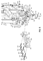
- each fluid passage 92, 94 includes a lengthwise portion 92a, 94a in one plate 100 and another lengthwise portion 92b, 94b in another plate 102 ( Fig. 5 ).
- Plates 100, 102, as well as other fluid contacting components are preferably made from a material that resists adherence to the particular fluid being dispensed.
- One material that generally has this property is acetal.
- the cartridges 74, 76 include respective fluid coupling ends 104, 106 which are received in bores 108, 110 of respective base elements 112, 114.
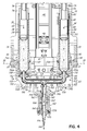
- Sealing rings 116, 118 including upper and lower O-rings 120 are provided between the plates 100, 102 of the dispensing portion 90 and base elements 112, 114 that receive the cartridge holders 32, 34.
- Sealing rings 116, 118 include respective tubular extensions 116a, 118a that receive the fluid coupling ends 104, 106.
- the cartridge holders 32, 34 are held in place to the base elements 112, 114 by pins 124, 126 which may be grasped and inserted or removed by use of rings 128, 130 (see Figs. 1 and 2 ).
- the pins 124, 126 are inserted into the respective base elements 112, 114 and enter annular grooves 132, 134 in the mounting elements 40, 42 of the cartridge holders 32, 34.
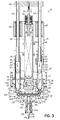
- the fluid As the fluid is driven out of the respective cartridges 74, 76 by the pistons 50, 52, the fluid travels into the first and second fluid passages 92, 94.
- the fluid travels from passages 92, 94 into an outlet passage 140 in a dispensing assembly 142 and flows out of an outlet 144.
- the dispensing assembly 142 is comprised of a connector element 146 having respective O-rings 148, 152 and coupling an outlet housing 156 to the dispensing portion 90.
- a series of spacers 160 and connecting elements 162 couple a fluid flow conduit 166 between the connector element 146 and an outlet connector element 170.
- a dispensing nozzle 174 is coupled to the outlet connecting element 170 and fastened in place by threaded fasteners 178.
- the cartridge holding assembly 16 When it is necessary or desirable to clean or otherwise maintain any part of the cartridge holding assembly 16, including the dispensing portion 90, the cartridge holding assembly 16 may be pivoted to the service position shown in Fig. 2 . If necessary, the cartridge holders 32, 34 may be easily lifted out of the base elements 74, 76 by removing the pins 124, 126 from the annular grooves 132, 134, grasping flats 180, 182 and removing the cartridge holders 32, 34 for service, cleaning and/or replacement. The dispensing portion 90 may be easily cleaned by releasing clasps 186, 188 on each side of the dispensing portion 90 (only two of four shown in Figs. 1 , 2 and 5 ) and removing the dispensing portion 90 from the base elements 74, 76.
- the entire dispensing portion 90 may be removed as a unit, and disassembled by removing the fasteners 105 associated with the plates 100, 102. If necessary, the fasteners 178 associated with the dispensing assembly and additional outlet components may be removed and the various parts easily cleaned of any residual fluid.
- the dispensing portion 90 Once the dispensing portion 90 is cleaned, it may be reassembled as a unit and then quickly fastened to the remaining portion of the cartridge holder assembly 16, i.e., to the base elements 74, 76 by fastening the front clasps 186, 188 and rear clasps 190, 192. It will be appreciated that the clasps may be substituted with other types of quick connectors.
Landscapes
- Engineering & Computer Science (AREA)
- Mechanical Engineering (AREA)
- Coating Apparatus (AREA)
- Chemical & Material Sciences (AREA)
- Dispersion Chemistry (AREA)
Abstract

Description
- This application claims the priority of
U.S. Provisional Patent Application Serial No. 61/880,413, filed on September 20, 2013 - The present invention generally relates to cartridge dispensing devices in which at least two cartridges simultaneously dispense one or more fluids from the cartridges.
- Various industries require the dispensing of viscous fluids, such as glues, sealants, epoxies, etc. Often, these fluids are provided in the form of pre-proportioned and mixed, single use cartridges. In the case of premixed cartridges of two component sealants, for example, the cartridges of fluid may be frozen. These cartridges are thawed and inserted individually into pneumatically operated caulking guns used by technicians who then manually apply the fluid to a product or workpiece. This is a time consuming and labor intensive process. Moreover, the apparatus typically used for these applications may be difficult to use and maintain.
- There is a need for fluid dispensers for simultaneously dispensing fluids from at least two cartridges, as well as related methods, enabling more efficient and productive use of the device as well as easier maintenance.
- In a first illustrative embodiment the invention provides a fluid dispenser for simultaneously dispensing fluids from first and second cartridges. It will be appreciated that the invention covers dispensers that are configured to simultaneously dispense from more than first and second cartridges, i.e., three or more cartridges. The fluid dispenser includes a base structure and a cartridge holding assembly mounted to the base structure. The cartridge holding assembly includes first and second cartridge holders. A linear drive mechanism is mounted to the base structure. First and second drive pistons are operatively connected to the linear drive mechanism and movable into respective first and second cartridges when the first and second cartridges are held in the first and second cartridge holders. In this manner fluids are simultaneously dispensed from the first and second cartridges.
- The first and second cartridge holders further comprise tubular members carried on the cartridge holding assembly, and also removable for maintenance and/or replacement. The cartridge holding assembly further comprises a dispensing portion including respective first and second fluid passages in fluid communication with the respective first and second cartridge holders. The first and second fluid passages receive the fluids from the first and second cartridges as the first and second drive pistons are driven into the first and second cartridges. An outlet passage communicates with the first and second fluid passages. The outlet passage dispenses the fluids from the first and second fluid passages.
- The dispensing portion further comprises first and second sections removably secured together, each section having lengthwise portions of the first and second passages therein for allowing cleaning of the lengthwise portions upon removal of the first section from the second section. The dispensing portion is removably secured to the first and second cartridge holders, preferably by at least one quick connector. In the illustrative embodiment, a plurality of clasps secures the dispensing portion to a remaining portion of the cartridge holding assembly.
- In another illustrative embodiment a fluid dispenser comprises a base structure and a cartridge holding assembly mounted to the base structure and including first and second cartridge holders. A linear drive mechanism is mounted to the base structure. First and second drive pistons are operatively connected to the linear drive mechanism. The linear drive mechanism drives the first and second drive pistons into respective first and second cartridges when the first and second cartridges are held in the first and second cartridge holders such that fluids are dispensed from the first and second cartridges. A dispensing portion includes respective first and second fluid passages in fluid communication with the respective first and second cartridge holders for receiving fluids from the first and second cartridges as the first and second drive pistons are moved into the first and second cartridges. The dispensing portion further comprises first and second sections removably secured together. Each section includes lengthwise portions of the first and second passages therein for allowing cleaning of the lengthwise portions upon removal of the first section from the second section.
- In another aspect, the invention provides a method of operating a fluid dispenser for simultaneously dispensing fluids from first and second cartridges. First and second cartridges are then loaded into respective first and second cartridge holders of the cartridge holding assembly. First and second pistons are then driven into the first and second cartridges to dispense fluids from the first and second cartridges.
- The invention provides a method of dispensing fluids and cleaning residual fluid from a fluid dispenser adapted to simultaneously dispense the fluids from first and second cartridges. This method generally includes loading first and second cartridges into respective first and second cartridge holders of the cartridge holding assembly. First and second pistons are respectively driven into the first and second cartridges to force fluids from the first and second cartridges. Fluid is thereby directed from the first and second cartridges respectively into first and second fluid passages of a dispensing portion. The fluids are dispensed from the first and second fluid passages, such as, by being directed through an outlet passage that combines the fluids. After dispensing, a first section of the dispensing portion is removed from a second section of the dispensing portion to expose respective lengthwise portions of the first and second fluid passages in the first and second sections. The lengthwise portions are then cleaned of residual fluid.
- These and other features of the various embodiments of this invention will become more readily apparent to those of ordinary skill upon review of the following detailed description of the illustrated embodiments taken in conjunction with the accompanying drawings
-
-
Fig. 1 is a perspective view illustrating a fluid dispenser constructed in accordance with an illustrative embodiment of the invention, and showing the cartridge holding assembly in an operating position. -
Fig. 2 is a perspective view similar toFig. 1 , but illustrating the cartridge holding assembly in a pivoted, service position. -
Fig. 3 is a longitudinal cross sectional view of the fluid dispenser shown inFig. 1 , with the pistons driven downward into the fluid cartridges. -
Fig. 4 is a cross sectional view similar toFig. 3 , but enlarged to better show details of the dispensing portion. -
Fig. 5 is a perspective view showing the dispensing portion disassembled. -
Figs. 1 and2 respectively illustrate afluid dispenser 10 in operating and service positions. Thefluid dispenser 10 includes abase structure 12 including abase plate 14 and acartridge holding assembly 16 is mounted to thebase structure 12. The connection between thecartridge holding assembly 16 andbase structure 12 is pivotal and includespivot mounts base plate 14, and twopivots 20, 21 (Fig. 4 ). Afluid cylinder 22, such as an air cylinder, is provided and includes an actuatingrod 24 coupled to apivoting mechanism 26. When therod 24 is extended as shown inFig. 1 , thecartridge holding assembly 16 is held in an operating position. When therod 24 is actuated to a retracted position as shown inFig. 2 , this pulls thepivoting mechanism 26 and pivots thecartridge holding assembly 16 about an axis 30 (Fig. 2 ) through thepivots Fig. 2 . Thecartridge holding assembly 16 includes first andsecond cartridge holders tubular members respective mounting elements cartridge holding assembly 16 may be modified to hold more than two cartridges, and the invention is not limited to dispensing simultaneously from only two cartridges but, rather, encompasses dispensing from more than two cartridges. Alinear drive mechanism 44 is mounted to thebase structure 12. Anelectrical connector 46 is provided for supplying power to the electric drive motor (not shown) associated with thelinear drive mechanism 44. Amagnetic brake 47 is provided for stopping thelinear drive mechanism 44 in the event that power is lost. - First and
second drive pistons linear drive mechanism 44. More specifically, thepistons rods linear bearings arrows Fig. 1 ) at an end opposite to thedrive pistons rods rods linear drive mechanism 44 via acentral rod 70. A bellows 72 protects the internal components of thelinear drive mechanism 44 from any environmental contaminants such as dirt or dust. First and secondfluid cartridges tubular members second cartridge holders Fig. 2 . Thecartridges cartridges plate 80 is rigidly coupled to thebase plate 14 and includes aslot 82 through which one of the cylindricalcartridge holder tubes 38 extends. The ends of thisslot 82 act as stops to ensure that thecartridge holders Figs. 1 and2 . - Now referring more specifically to
Figs. 3-5 , thecartridge holding assembly 16 further comprises a dispensingportion 90 including respective first and secondfluid passages second cartridge holders fluid passage lengthwise portion 92a, 94a in oneplate 100 and anotherlengthwise portion Fig. 5 ).Plates plates fastener elements 104, a complete set of twofluid passages fluid passages second cartridge holders Fig. 4 ,respective seals lengthwise portions plates fluid passages second cartridges cartridges cartridge holders cartridges bores respective base elements rings 120 are provided between theplates portion 90 andbase elements cartridge holders tubular extensions cartridge holders base elements pins rings 128, 130 (seeFigs. 1 and2 ). Specifically, thepins respective base elements annular grooves elements cartridge holders respective cartridges pistons fluid passages passages outlet passage 140 in a dispensingassembly 142 and flows out of anoutlet 144. The dispensingassembly 142 is comprised of aconnector element 146 having respective O-rings outlet housing 156 to the dispensingportion 90. A series ofspacers 160 and connectingelements 162 couple afluid flow conduit 166 between theconnector element 146 and anoutlet connector element 170. A dispensingnozzle 174 is coupled to theoutlet connecting element 170 and fastened in place by threadedfasteners 178. - When it is necessary or desirable to clean or otherwise maintain any part of the
cartridge holding assembly 16, including the dispensingportion 90, thecartridge holding assembly 16 may be pivoted to the service position shown inFig. 2 . If necessary, thecartridge holders base elements pins annular grooves flats cartridge holders portion 90 may be easily cleaned by releasingclasps Figs. 1 ,2 and5 ) and removing the dispensingportion 90 from thebase elements portion 90 may be removed as a unit, and disassembled by removing thefasteners 105 associated with theplates fasteners 178 associated with the dispensing assembly and additional outlet components may be removed and the various parts easily cleaned of any residual fluid. Once the dispensingportion 90 is cleaned, it may be reassembled as a unit and then quickly fastened to the remaining portion of thecartridge holder assembly 16, i.e., to thebase elements rear clasps - While the present invention has been illustrated by the description of one or more embodiments thereof, and while the embodiments have been described in considerable detail, they are not intended to restrict or in any way limit the scope of the appended claims to such detail. The various features shown and described herein may be used alone or in any combination. Additional advantages and modifications will readily appear to those skilled in the art. The invention in its broader aspects is therefore not limited to the specific details, representative apparatus and method and illustrative examples shown and described. Accordingly, departures may be from such details without departing from the scope of the general inventive concept.
Claims (7)
- A fluid dispenser for simultaneously dispensing fluids from first and second cartridges, comprising:a base structure;a cartridge holding assembly mounted to said base structure and including first and second cartridge holders;a linear drive mechanism mounted to said base structure;first and second drive pistons operatively connected to said linear drive mechanism and movable into respective first and second cartridges when said first and second cartridges are held in said first and second cartridge holders such that fluid is dispensed from the first and second cartridges; anda dispensing portion including respective first and second fluid passages in fluid communication with the respective first and second cartridge holders for receiving fluid from the first and second cartridges as the first and second drive pistons are moved into the first and second cartridges, said dispensing portion further comprising first and second sections removably secured together, each section having lengthwise portions of said first and second passages therein for allowing cleaning of the lengthwise portions upon removal of the first section from the second section.
- The fluid dispenser of claim 1, wherein said dispensing portion further comprises an outlet passage communicating with the first and second fluid passages for receiving and dispensing the fluid from the first and second fluid passages.
- The fluid dispenser of claim 1, wherein said first and second cartridge holders further comprise tubular members removably carried on said cartridge holding assembly.
- The fluid dispenser of claim 1, wherein said dispensing portion is removably secured to said first and second cartridge holders.
- The fluid dispenser of claim 4, wherein said dispensing portion is removably secured to said first and second cartridge holders by at least one quick connector.
- A method of dispensing fluids and cleaning residual fluid from a fluid dispenser adapted to simultaneously dispense the fluids from first and second cartridges, comprising:loading first and second cartridges into respective first and second cartridge holders of the cartridge holding assembly;driving first and second pistons respectively into the first and second cartridges to force fluids from the first and second cartridges;directing the fluids from the first and second cartridges respectively into first and second fluid passages of a dispensing portion;dispensing the fluids from the first and second fluid passages;removing a first section of the dispensing portion from a second section of the dispensing portion to expose respective lengthwise portions of the first and second fluid passages in the first and second sections; andcleaning the lengthwise portions of residual fluid.
- The method of claim 6, further comprising:removing the dispensing portion from the first and second cartridge holders prior to cleaning the lengthwise portions of residual fluid.
Applications Claiming Priority (2)
| Application Number | Priority Date | Filing Date | Title |
|---|---|---|---|
| US201361880413P | 2013-09-20 | 2013-09-20 | |
| US14/487,523 US9656286B2 (en) | 2013-09-20 | 2014-09-16 | Fluid dispenser and method for simultaneously dispensing fluids from multiple cartridges |
Publications (2)
| Publication Number | Publication Date |
|---|---|
| EP2851133A1 true EP2851133A1 (en) | 2015-03-25 |
| EP2851133B1 EP2851133B1 (en) | 2017-08-23 |
Family
ID=51564563
Family Applications (1)
| Application Number | Title | Priority Date | Filing Date |
|---|---|---|---|
| EP14185437.2A Not-in-force EP2851133B1 (en) | 2013-09-20 | 2014-09-18 | Fluid dispenser and method for simultaneously dispensing fluids from multiple cartridges |
Country Status (3)
| Country | Link |
|---|---|
| US (1) | US9656286B2 (en) |
| EP (1) | EP2851133B1 (en) |
| ES (1) | ES2645513T3 (en) |
Cited By (3)
| Publication number | Priority date | Publication date | Assignee | Title |
|---|---|---|---|---|
| US20160361734A1 (en) | 2015-06-11 | 2016-12-15 | Nordson Corporation | Cartridge type fluid dispensing apparatus and methods |
| EP3381573A3 (en) * | 2017-02-07 | 2018-11-07 | Nordson Corporation | Motorized cartridge type fluid dispensing apparatus and system |
| EP3738680A1 (en) * | 2019-05-14 | 2020-11-18 | Arrival Limited | Two-component dispensing tool with cartridge replacement mechanism |
Families Citing this family (7)
| Publication number | Priority date | Publication date | Assignee | Title |
|---|---|---|---|---|
| US10518289B2 (en) * | 2015-10-15 | 2019-12-31 | The Boeing Company | Apparatuses for applying glutinous substances |
| US10363569B2 (en) | 2015-10-15 | 2019-07-30 | The Boeing Company | Applicators and systems for delivering a glutinous substance to a workpiece from an end-effector |
| US9862001B2 (en) * | 2015-12-31 | 2018-01-09 | Sulzer Mixpac Ag | Dispensing device |
| US10507478B2 (en) | 2016-03-30 | 2019-12-17 | The Patent Well LLC | Clear sprayable sealant for aircraft parts and assemblies |
| CN107931018A (en) * | 2017-12-27 | 2018-04-20 | 苏州华控注胶技术有限公司 | A kind of piston fixed mechanism for glue-injection machine pressure apparatus |
| CN107983592A (en) * | 2017-12-27 | 2018-05-04 | 苏州华控注胶技术有限公司 | A kind of glue mixing device and its glue-injection machine easy to cleaning |
| US12227351B1 (en) * | 2021-11-08 | 2025-02-18 | Diamond Age 3D, Inc. | Reusable cartridge based system for precision placement of construction materials |
Citations (6)
| Publication number | Priority date | Publication date | Assignee | Title |
|---|---|---|---|---|
| US4773562A (en) * | 1986-09-04 | 1988-09-27 | L'oreal | Dispenser head for mixing separate pasty substances and a storage unit provided with such a dispenser head |
| CH674717A5 (en) * | 1987-11-10 | 1990-07-13 | Profil Ag | Mixing device for at least two cartridges - has mixing head, semi-outer welded shells, supplies, strips or screw conveyor |
| EP1260330A2 (en) * | 2001-05-18 | 2002-11-27 | SCM GROUP S.p.A. | A glue feed unit in particular for machines which process wooden panels |
| WO2007044535A2 (en) * | 2005-10-06 | 2007-04-19 | Mixtek System, Llc | Dispensing device for multiple constituent systems |
| WO2012113457A1 (en) * | 2011-02-25 | 2012-08-30 | Brainlink Gmbh | Reusable frothing device |
| WO2013109180A2 (en) * | 2012-01-19 | 2013-07-25 | Nolato Silikonteknik Ab | Device and method for producing an element for electromagnetic shielding |
Family Cites Families (25)
| Publication number | Priority date | Publication date | Assignee | Title |
|---|---|---|---|---|
| US1905733A (en) * | 1932-03-18 | 1933-04-25 | Texas Co | Flow divider |
| US3128710A (en) * | 1960-09-19 | 1964-04-14 | Oscar C Blomgren | Gear pump |
| US3884388A (en) * | 1973-04-26 | 1975-05-20 | Cornelius Co | Mixing device for a beverage dispenser |
| US4067479A (en) * | 1975-07-31 | 1978-01-10 | Products Research & Chemical Corporation | Two part material meter-mix dispenser apparatus |
| EP0236129A3 (en) * | 1986-03-03 | 1988-08-24 | P.C. Cox (Newbury) Limited | Pneumatic dispensers for viscous materials |
| NL9200984A (en) | 1992-06-04 | 1994-01-03 | Nordson Nederland | METHOD AND APPARATUS FOR APPLICATING LIQUID MATERIAL, IN PARTICULAR A HOT MELT, ON A SUBSTRATE BY SEQUENTIALLY ACTING APPLICATOR |
| FR2722431B1 (en) * | 1994-07-12 | 1996-09-13 | Lir France Sa | DOUBLE DISPENSER FOR FLUID PRODUCTS |
| DE19500782A1 (en) * | 1995-01-13 | 1996-07-18 | Bayer Ag | Device for mixing and applying a molding compound |
| US5795390A (en) | 1995-08-24 | 1998-08-18 | Camelot Systems, Inc. | Liquid dispensing system with multiple cartridges |
| US6214117B1 (en) | 1998-03-02 | 2001-04-10 | Speedline Technologies, Inc. | Dispensing system and method |
| US6168335B1 (en) * | 1998-08-18 | 2001-01-02 | Arich, Inc. | Applicator and dispensing device using same |
| ES2307504T3 (en) | 1999-04-06 | 2008-12-01 | Fishman Corporation | ELECTRONIC FLUID DISPENSER. |
| EP1072323B1 (en) * | 1999-07-29 | 2003-09-10 | Wilhelm A. Keller | Cartridge discharge device with actuator for dynamic mixers |
| US6308868B1 (en) * | 1999-09-20 | 2001-10-30 | Liquid Control Corporation | High pressure cartridge feed system |
| GB0012931D0 (en) * | 2000-05-26 | 2000-07-19 | Constance Ltd | Fluid bags |
| US6540113B2 (en) * | 2001-02-01 | 2003-04-01 | Dispensing Technologies International Corporation | Fluid dispenser particularly adapted for hand-held operation |
| US6488180B1 (en) * | 2001-04-02 | 2002-12-03 | John Jahangir Bayat | Power operated caulking gun |
| US6889872B2 (en) * | 2002-06-28 | 2005-05-10 | Meritool, L.L.C. | Electric two-part material dispenser |
| US6981656B2 (en) | 2003-04-11 | 2006-01-03 | Nordson Corporation | Quick cleaning hot melt adhesive dispensing apparatus |
| US8789725B2 (en) * | 2004-03-29 | 2014-07-29 | P G United States Israel Ltd. | Foam dispenser nozzle |
| US7811072B2 (en) * | 2007-07-10 | 2010-10-12 | Private Brand Tool (Australia) Pty Ltd. | Gear pump |
| US7905375B2 (en) * | 2008-07-31 | 2011-03-15 | Albion Engineering Company | Dispensing device arranged to reduce the risk of strain and injury during use |
| EP2382941A1 (en) * | 2010-04-29 | 2011-11-02 | 3M Innovative Properties Company | A system comprising a mixing and dispensing device and a material container |
| US9999989B2 (en) * | 2010-12-30 | 2018-06-19 | United States Gypsum Company | Slurry distributor with a profiling mechanism, system, and method for using same |
| EP2604152B1 (en) * | 2011-12-15 | 2014-06-04 | Nestec S.A. | Beverage dispenser with improved outlet tubes assembly |
-
2014
- 2014-09-16 US US14/487,523 patent/US9656286B2/en not_active Expired - Fee Related
- 2014-09-18 EP EP14185437.2A patent/EP2851133B1/en not_active Not-in-force
- 2014-09-18 ES ES14185437.2T patent/ES2645513T3/en active Active
Patent Citations (6)
| Publication number | Priority date | Publication date | Assignee | Title |
|---|---|---|---|---|
| US4773562A (en) * | 1986-09-04 | 1988-09-27 | L'oreal | Dispenser head for mixing separate pasty substances and a storage unit provided with such a dispenser head |
| CH674717A5 (en) * | 1987-11-10 | 1990-07-13 | Profil Ag | Mixing device for at least two cartridges - has mixing head, semi-outer welded shells, supplies, strips or screw conveyor |
| EP1260330A2 (en) * | 2001-05-18 | 2002-11-27 | SCM GROUP S.p.A. | A glue feed unit in particular for machines which process wooden panels |
| WO2007044535A2 (en) * | 2005-10-06 | 2007-04-19 | Mixtek System, Llc | Dispensing device for multiple constituent systems |
| WO2012113457A1 (en) * | 2011-02-25 | 2012-08-30 | Brainlink Gmbh | Reusable frothing device |
| WO2013109180A2 (en) * | 2012-01-19 | 2013-07-25 | Nolato Silikonteknik Ab | Device and method for producing an element for electromagnetic shielding |
Cited By (7)
| Publication number | Priority date | Publication date | Assignee | Title |
|---|---|---|---|---|
| US20160361734A1 (en) | 2015-06-11 | 2016-12-15 | Nordson Corporation | Cartridge type fluid dispensing apparatus and methods |
| US10682666B2 (en) | 2015-06-11 | 2020-06-16 | Nordson Corporation | Cartridge type fluid dispensing apparatus and methods |
| EP3381573A3 (en) * | 2017-02-07 | 2018-11-07 | Nordson Corporation | Motorized cartridge type fluid dispensing apparatus and system |
| US10675653B2 (en) | 2017-02-07 | 2020-06-09 | Nordson Corporation | Motorized cartridge type fluid dispensing apparatus and system |
| EP3738680A1 (en) * | 2019-05-14 | 2020-11-18 | Arrival Limited | Two-component dispensing tool with cartridge replacement mechanism |
| GB2584082A (en) * | 2019-05-14 | 2020-11-25 | Arrival Ltd | Two-component dispensing tool with cartridge replacement mechanism |
| GB2584082B (en) * | 2019-05-14 | 2021-09-22 | Arrival Ltd | Two-component dispensing tool with cartridge replacement mechanism |
Also Published As
| Publication number | Publication date |
|---|---|
| EP2851133B1 (en) | 2017-08-23 |
| ES2645513T3 (en) | 2017-12-05 |
| US9656286B2 (en) | 2017-05-23 |
| US20150083751A1 (en) | 2015-03-26 |
Similar Documents
| Publication | Publication Date | Title |
|---|---|---|
| US9656286B2 (en) | Fluid dispenser and method for simultaneously dispensing fluids from multiple cartridges | |
| US9387504B2 (en) | Cartridge dispenser | |
| KR102023523B1 (en) | Liquid dispensing apparatus, coating apparatus for same, and liquid dispensing method | |
| US20140326760A1 (en) | Control Valve Having a Disposable Valve Body | |
| JP6362962B2 (en) | Apparatus for applying fluid on a surface | |
| CN101466479B (en) | Coating device and associated operating method | |
| JP2015061722A (en) | NOZZLE AND TIP EXCHANGE METHOD IN FLUID DISTRIBUTION SYSTEM, NOZZLE AND TIP EXCHANGE DEVICE | |
| US20190154719A1 (en) | Liquid dispenser with manifold mount for modular independently-actuated pipette channels | |
| WO2014126675A1 (en) | Fluid application device | |
| US10105730B2 (en) | Robotic cartridge dispenser and method | |
| EA034041B1 (en) | System for cleaning an object such as a heat exchanger | |
| US10300504B2 (en) | Spray system pump wash sequence | |
| WO2008000799A1 (en) | Device for dispensing material for processing and use of said device | |
| US20080185097A1 (en) | Positive displacement plural-component finishing dispenser system and method | |
| US11583876B2 (en) | Positive displacement end effector with multiple cartridges | |
| DE202017006214U1 (en) | Cleaning polishing device | |
| US12485673B2 (en) | Nozzle plate and liquid discharge apparatus | |
| CN108339719B (en) | coloring device | |
| US20120255970A1 (en) | Method for efficient and precise transfer of liquids | |
| DE102016200960A1 (en) | pumping device | |
| EP1489426A2 (en) | System for dosing samples of liquids | |
| EP3015174A1 (en) | Coating system for coating objects | |
| DE102014200696A1 (en) | Cartridge dispenser for dispensing e.g. sealant for manufacture of e.g. airplane, has sensor to sense a data related to flowable material that is flowed from cartridge through outlet opening, and to feedback for controlling actuator | |
| EP3017873B1 (en) | Coating system for coating objects |
Legal Events
| Date | Code | Title | Description |
|---|---|---|---|
| PUAI | Public reference made under article 153(3) epc to a published international application that has entered the european phase |
Free format text: ORIGINAL CODE: 0009012 |
|
| 17P | Request for examination filed |
Effective date: 20140918 |
|
| AK | Designated contracting states |
Kind code of ref document: A1 Designated state(s): AL AT BE BG CH CY CZ DE DK EE ES FI FR GB GR HR HU IE IS IT LI LT LU LV MC MK MT NL NO PL PT RO RS SE SI SK SM TR |
|
| AX | Request for extension of the european patent |
Extension state: BA ME |
|
| R17P | Request for examination filed (corrected) |
Effective date: 20150925 |
|
| RBV | Designated contracting states (corrected) |
Designated state(s): AL AT BE BG CH CY CZ DE DK EE ES FI FR GB GR HR HU IE IS IT LI LT LU LV MC MK MT NL NO PL PT RO RS SE SI SK SM TR |
|
| REG | Reference to a national code |
Ref country code: DE Ref legal event code: R079 Ref document number: 602014013404 Country of ref document: DE Free format text: PREVIOUS MAIN CLASS: B05C0005020000 Ipc: B05C0017005000 |
|
| GRAP | Despatch of communication of intention to grant a patent |
Free format text: ORIGINAL CODE: EPIDOSNIGR1 |
|
| RIC1 | Information provided on ipc code assigned before grant |
Ipc: B05C 17/005 20060101AFI20170207BHEP Ipc: B05B 15/02 20060101ALN20170207BHEP Ipc: B05C 17/01 20060101ALI20170207BHEP |
|
| INTG | Intention to grant announced |
Effective date: 20170307 |
|
| GRAS | Grant fee paid |
Free format text: ORIGINAL CODE: EPIDOSNIGR3 |
|
| GRAA | (expected) grant |
Free format text: ORIGINAL CODE: 0009210 |
|
| AK | Designated contracting states |
Kind code of ref document: B1 Designated state(s): AL AT BE BG CH CY CZ DE DK EE ES FI FR GB GR HR HU IE IS IT LI LT LU LV MC MK MT NL NO PL PT RO RS SE SI SK SM TR |
|
| REG | Reference to a national code |
Ref country code: GB Ref legal event code: FG4D |
|
| REG | Reference to a national code |
Ref country code: CH Ref legal event code: EP Ref country code: CH Ref legal event code: NV Representative=s name: WEINMANN ZIMMERLI, CH |
|
| REG | Reference to a national code |
Ref country code: AT Ref legal event code: REF Ref document number: 920776 Country of ref document: AT Kind code of ref document: T Effective date: 20170915 |
|
| REG | Reference to a national code |
Ref country code: IE Ref legal event code: FG4D |
|
| REG | Reference to a national code |
Ref country code: DE Ref legal event code: R096 Ref document number: 602014013404 Country of ref document: DE |
|
| REG | Reference to a national code |
Ref country code: FR Ref legal event code: PLFP Year of fee payment: 4 |
|
| REG | Reference to a national code |
Ref country code: ES Ref legal event code: FG2A Ref document number: 2645513 Country of ref document: ES Kind code of ref document: T3 Effective date: 20171205 |
|
| REG | Reference to a national code |
Ref country code: NL Ref legal event code: MP Effective date: 20170823 |
|
| REG | Reference to a national code |
Ref country code: LT Ref legal event code: MG4D |
|
| REG | Reference to a national code |
Ref country code: AT Ref legal event code: MK05 Ref document number: 920776 Country of ref document: AT Kind code of ref document: T Effective date: 20170823 |
|
| PG25 | Lapsed in a contracting state [announced via postgrant information from national office to epo] |
Ref country code: LT Free format text: LAPSE BECAUSE OF FAILURE TO SUBMIT A TRANSLATION OF THE DESCRIPTION OR TO PAY THE FEE WITHIN THE PRESCRIBED TIME-LIMIT Effective date: 20170823 Ref country code: HR Free format text: LAPSE BECAUSE OF FAILURE TO SUBMIT A TRANSLATION OF THE DESCRIPTION OR TO PAY THE FEE WITHIN THE PRESCRIBED TIME-LIMIT Effective date: 20170823 Ref country code: SE Free format text: LAPSE BECAUSE OF FAILURE TO SUBMIT A TRANSLATION OF THE DESCRIPTION OR TO PAY THE FEE WITHIN THE PRESCRIBED TIME-LIMIT Effective date: 20170823 Ref country code: NO Free format text: LAPSE BECAUSE OF FAILURE TO SUBMIT A TRANSLATION OF THE DESCRIPTION OR TO PAY THE FEE WITHIN THE PRESCRIBED TIME-LIMIT Effective date: 20171123 Ref country code: FI Free format text: LAPSE BECAUSE OF FAILURE TO SUBMIT A TRANSLATION OF THE DESCRIPTION OR TO PAY THE FEE WITHIN THE PRESCRIBED TIME-LIMIT Effective date: 20170823 Ref country code: AT Free format text: LAPSE BECAUSE OF FAILURE TO SUBMIT A TRANSLATION OF THE DESCRIPTION OR TO PAY THE FEE WITHIN THE PRESCRIBED TIME-LIMIT Effective date: 20170823 Ref country code: NL Free format text: LAPSE BECAUSE OF FAILURE TO SUBMIT A TRANSLATION OF THE DESCRIPTION OR TO PAY THE FEE WITHIN THE PRESCRIBED TIME-LIMIT Effective date: 20170823 |
|
| PG25 | Lapsed in a contracting state [announced via postgrant information from national office to epo] |
Ref country code: GR Free format text: LAPSE BECAUSE OF FAILURE TO SUBMIT A TRANSLATION OF THE DESCRIPTION OR TO PAY THE FEE WITHIN THE PRESCRIBED TIME-LIMIT Effective date: 20171124 Ref country code: PL Free format text: LAPSE BECAUSE OF FAILURE TO SUBMIT A TRANSLATION OF THE DESCRIPTION OR TO PAY THE FEE WITHIN THE PRESCRIBED TIME-LIMIT Effective date: 20170823 Ref country code: RS Free format text: LAPSE BECAUSE OF FAILURE TO SUBMIT A TRANSLATION OF THE DESCRIPTION OR TO PAY THE FEE WITHIN THE PRESCRIBED TIME-LIMIT Effective date: 20170823 Ref country code: LV Free format text: LAPSE BECAUSE OF FAILURE TO SUBMIT A TRANSLATION OF THE DESCRIPTION OR TO PAY THE FEE WITHIN THE PRESCRIBED TIME-LIMIT Effective date: 20170823 Ref country code: IS Free format text: LAPSE BECAUSE OF FAILURE TO SUBMIT A TRANSLATION OF THE DESCRIPTION OR TO PAY THE FEE WITHIN THE PRESCRIBED TIME-LIMIT Effective date: 20171223 Ref country code: BG Free format text: LAPSE BECAUSE OF FAILURE TO SUBMIT A TRANSLATION OF THE DESCRIPTION OR TO PAY THE FEE WITHIN THE PRESCRIBED TIME-LIMIT Effective date: 20171123 |
|
| PG25 | Lapsed in a contracting state [announced via postgrant information from national office to epo] |
Ref country code: CZ Free format text: LAPSE BECAUSE OF FAILURE TO SUBMIT A TRANSLATION OF THE DESCRIPTION OR TO PAY THE FEE WITHIN THE PRESCRIBED TIME-LIMIT Effective date: 20170823 Ref country code: DK Free format text: LAPSE BECAUSE OF FAILURE TO SUBMIT A TRANSLATION OF THE DESCRIPTION OR TO PAY THE FEE WITHIN THE PRESCRIBED TIME-LIMIT Effective date: 20170823 Ref country code: RO Free format text: LAPSE BECAUSE OF FAILURE TO SUBMIT A TRANSLATION OF THE DESCRIPTION OR TO PAY THE FEE WITHIN THE PRESCRIBED TIME-LIMIT Effective date: 20170823 |
|
| REG | Reference to a national code |
Ref country code: DE Ref legal event code: R097 Ref document number: 602014013404 Country of ref document: DE |
|
| PG25 | Lapsed in a contracting state [announced via postgrant information from national office to epo] |
Ref country code: EE Free format text: LAPSE BECAUSE OF FAILURE TO SUBMIT A TRANSLATION OF THE DESCRIPTION OR TO PAY THE FEE WITHIN THE PRESCRIBED TIME-LIMIT Effective date: 20170823 Ref country code: SM Free format text: LAPSE BECAUSE OF FAILURE TO SUBMIT A TRANSLATION OF THE DESCRIPTION OR TO PAY THE FEE WITHIN THE PRESCRIBED TIME-LIMIT Effective date: 20170823 Ref country code: SK Free format text: LAPSE BECAUSE OF FAILURE TO SUBMIT A TRANSLATION OF THE DESCRIPTION OR TO PAY THE FEE WITHIN THE PRESCRIBED TIME-LIMIT Effective date: 20170823 Ref country code: MC Free format text: LAPSE BECAUSE OF FAILURE TO SUBMIT A TRANSLATION OF THE DESCRIPTION OR TO PAY THE FEE WITHIN THE PRESCRIBED TIME-LIMIT Effective date: 20170823 |
|
| REG | Reference to a national code |
Ref country code: IE Ref legal event code: MM4A |
|
| REG | Reference to a national code |
Ref country code: BE Ref legal event code: MM Effective date: 20170930 |
|
| PG25 | Lapsed in a contracting state [announced via postgrant information from national office to epo] |
Ref country code: LU Free format text: LAPSE BECAUSE OF NON-PAYMENT OF DUE FEES Effective date: 20170918 |
|
| PLBE | No opposition filed within time limit |
Free format text: ORIGINAL CODE: 0009261 |
|
| STAA | Information on the status of an ep patent application or granted ep patent |
Free format text: STATUS: NO OPPOSITION FILED WITHIN TIME LIMIT |
|
| PG25 | Lapsed in a contracting state [announced via postgrant information from national office to epo] |
Ref country code: IE Free format text: LAPSE BECAUSE OF NON-PAYMENT OF DUE FEES Effective date: 20170918 |
|
| 26N | No opposition filed |
Effective date: 20180524 |
|
| PG25 | Lapsed in a contracting state [announced via postgrant information from national office to epo] |
Ref country code: SI Free format text: LAPSE BECAUSE OF FAILURE TO SUBMIT A TRANSLATION OF THE DESCRIPTION OR TO PAY THE FEE WITHIN THE PRESCRIBED TIME-LIMIT Effective date: 20170823 Ref country code: BE Free format text: LAPSE BECAUSE OF NON-PAYMENT OF DUE FEES Effective date: 20170930 |
|
| REG | Reference to a national code |
Ref country code: FR Ref legal event code: PLFP Year of fee payment: 5 |
|
| PG25 | Lapsed in a contracting state [announced via postgrant information from national office to epo] |
Ref country code: MT Free format text: LAPSE BECAUSE OF NON-PAYMENT OF DUE FEES Effective date: 20170918 |
|
| PG25 | Lapsed in a contracting state [announced via postgrant information from national office to epo] |
Ref country code: HU Free format text: LAPSE BECAUSE OF FAILURE TO SUBMIT A TRANSLATION OF THE DESCRIPTION OR TO PAY THE FEE WITHIN THE PRESCRIBED TIME-LIMIT; INVALID AB INITIO Effective date: 20140918 |
|
| PG25 | Lapsed in a contracting state [announced via postgrant information from national office to epo] |
Ref country code: CY Free format text: LAPSE BECAUSE OF FAILURE TO SUBMIT A TRANSLATION OF THE DESCRIPTION OR TO PAY THE FEE WITHIN THE PRESCRIBED TIME-LIMIT Effective date: 20170823 |
|
| PG25 | Lapsed in a contracting state [announced via postgrant information from national office to epo] |
Ref country code: MK Free format text: LAPSE BECAUSE OF FAILURE TO SUBMIT A TRANSLATION OF THE DESCRIPTION OR TO PAY THE FEE WITHIN THE PRESCRIBED TIME-LIMIT Effective date: 20170823 |
|
| PG25 | Lapsed in a contracting state [announced via postgrant information from national office to epo] |
Ref country code: TR Free format text: LAPSE BECAUSE OF FAILURE TO SUBMIT A TRANSLATION OF THE DESCRIPTION OR TO PAY THE FEE WITHIN THE PRESCRIBED TIME-LIMIT Effective date: 20170823 |
|
| PG25 | Lapsed in a contracting state [announced via postgrant information from national office to epo] |
Ref country code: PT Free format text: LAPSE BECAUSE OF FAILURE TO SUBMIT A TRANSLATION OF THE DESCRIPTION OR TO PAY THE FEE WITHIN THE PRESCRIBED TIME-LIMIT Effective date: 20170823 |
|
| PG25 | Lapsed in a contracting state [announced via postgrant information from national office to epo] |
Ref country code: AL Free format text: LAPSE BECAUSE OF FAILURE TO SUBMIT A TRANSLATION OF THE DESCRIPTION OR TO PAY THE FEE WITHIN THE PRESCRIBED TIME-LIMIT Effective date: 20170823 |
|
| PGFP | Annual fee paid to national office [announced via postgrant information from national office to epo] |
Ref country code: FR Payment date: 20200914 Year of fee payment: 7 Ref country code: GB Payment date: 20200922 Year of fee payment: 7 Ref country code: DE Payment date: 20200925 Year of fee payment: 7 |
|
| PGFP | Annual fee paid to national office [announced via postgrant information from national office to epo] |
Ref country code: CH Payment date: 20200921 Year of fee payment: 7 Ref country code: IT Payment date: 20200922 Year of fee payment: 7 |
|
| PGFP | Annual fee paid to national office [announced via postgrant information from national office to epo] |
Ref country code: ES Payment date: 20201120 Year of fee payment: 7 |
|
| REG | Reference to a national code |
Ref country code: DE Ref legal event code: R119 Ref document number: 602014013404 Country of ref document: DE |
|
| REG | Reference to a national code |
Ref country code: CH Ref legal event code: PL |
|
| GBPC | Gb: european patent ceased through non-payment of renewal fee |
Effective date: 20210918 |
|
| PG25 | Lapsed in a contracting state [announced via postgrant information from national office to epo] |
Ref country code: GB Free format text: LAPSE BECAUSE OF NON-PAYMENT OF DUE FEES Effective date: 20210918 Ref country code: FR Free format text: LAPSE BECAUSE OF NON-PAYMENT OF DUE FEES Effective date: 20210930 Ref country code: DE Free format text: LAPSE BECAUSE OF NON-PAYMENT OF DUE FEES Effective date: 20220401 |
|
| PG25 | Lapsed in a contracting state [announced via postgrant information from national office to epo] |
Ref country code: LI Free format text: LAPSE BECAUSE OF NON-PAYMENT OF DUE FEES Effective date: 20210930 Ref country code: CH Free format text: LAPSE BECAUSE OF NON-PAYMENT OF DUE FEES Effective date: 20210930 |
|
| PG25 | Lapsed in a contracting state [announced via postgrant information from national office to epo] |
Ref country code: IT Free format text: LAPSE BECAUSE OF NON-PAYMENT OF DUE FEES Effective date: 20210918 |
|
| REG | Reference to a national code |
Ref country code: ES Ref legal event code: FD2A Effective date: 20221107 |
|
| PG25 | Lapsed in a contracting state [announced via postgrant information from national office to epo] |
Ref country code: ES Free format text: LAPSE BECAUSE OF NON-PAYMENT OF DUE FEES Effective date: 20210919 |