EP2850874B1 - Signaling framework for assistance information - Google Patents
Signaling framework for assistance information Download PDFInfo
- Publication number
- EP2850874B1 EP2850874B1 EP12721284.3A EP12721284A EP2850874B1 EP 2850874 B1 EP2850874 B1 EP 2850874B1 EP 12721284 A EP12721284 A EP 12721284A EP 2850874 B1 EP2850874 B1 EP 2850874B1
- Authority
- EP
- European Patent Office
- Prior art keywords
- base station
- user equipment
- assistance information
- target base
- signaling message
- Prior art date
- Legal status (The legal status is an assumption and is not a legal conclusion. Google has not performed a legal analysis and makes no representation as to the accuracy of the status listed.)
- Active
Links
- 230000011664 signaling Effects 0.000 title claims description 68
- 238000000034 method Methods 0.000 claims description 16
- 238000004590 computer program Methods 0.000 claims description 8
- 230000007774 longterm Effects 0.000 claims 4
- 230000002401 inhibitory effect Effects 0.000 claims 1
- 230000006870 function Effects 0.000 description 8
- 238000012545 processing Methods 0.000 description 7
- 238000010586 diagram Methods 0.000 description 4
- 238000012986 modification Methods 0.000 description 2
- 230000004048 modification Effects 0.000 description 2
- 239000004065 semiconductor Substances 0.000 description 2
- 238000003491 array Methods 0.000 description 1
- 230000009286 beneficial effect Effects 0.000 description 1
- 230000005540 biological transmission Effects 0.000 description 1
- 230000000295 complement effect Effects 0.000 description 1
- 238000012790 confirmation Methods 0.000 description 1
- 230000001419 dependent effect Effects 0.000 description 1
- 229910044991 metal oxide Inorganic materials 0.000 description 1
- 150000004706 metal oxides Chemical class 0.000 description 1
- 238000012546 transfer Methods 0.000 description 1
- 230000001960 triggered effect Effects 0.000 description 1
Images


Classifications
-
- H—ELECTRICITY
- H04—ELECTRIC COMMUNICATION TECHNIQUE
- H04W—WIRELESS COMMUNICATION NETWORKS
- H04W36/00—Hand-off or reselection arrangements
- H04W36/0005—Control or signalling for completing the hand-off
- H04W36/0055—Transmission or use of information for re-establishing the radio link
- H04W36/0072—Transmission or use of information for re-establishing the radio link of resource information of target access point
-
- H—ELECTRICITY
- H04—ELECTRIC COMMUNICATION TECHNIQUE
- H04W—WIRELESS COMMUNICATION NETWORKS
- H04W36/00—Hand-off or reselection arrangements
- H04W36/0005—Control or signalling for completing the hand-off
- H04W36/0011—Control or signalling for completing the hand-off for data sessions of end-to-end connection
- H04W36/0016—Hand-off preparation specially adapted for end-to-end data sessions
-
- H—ELECTRICITY
- H04—ELECTRIC COMMUNICATION TECHNIQUE
- H04W—WIRELESS COMMUNICATION NETWORKS
- H04W76/00—Connection management
- H04W76/10—Connection setup
- H04W76/19—Connection re-establishment
-
- H—ELECTRICITY
- H04—ELECTRIC COMMUNICATION TECHNIQUE
- H04W—WIRELESS COMMUNICATION NETWORKS
- H04W36/00—Hand-off or reselection arrangements
- H04W36/08—Reselecting an access point
Definitions
- the present invention relates to a signaling framework for assistance information. More particularly, the present invention relates to methods, apparatuses and a program relating to a signaling framework for assistance information, for example, in LTE.
- One of the problems related to the handling of assistance information is that the UE needs to know whether the eNB supports the signalling. Further, at handover, the overhead needs to be minimized. Another problem in this regard is that mobility across eNBs of different releases or having different set of functionalities must be supported.
- the UE For mobility, it has been proposed that the UE should follow an order given by the target cell whether to report the assistance information after handover or not, as described in document [3]. Further, the options of UE receiving the confirmation of [assistance-information] context transfer from a target cell, and of UE always reporting assistance information after handover have been discussed in document [4].
- proximity reporting of CSG cells is enabled by network (NW) dedicated configuration to the UE ( otherConfig in RRC specification [5]).
- NW network
- UE will only report proximity of closed subscriber group (CSG) cells if configured by the NW. Proximity status is not transferred between cells and thus UE needs retransmit proximity at cell change if UE still considers proximity being valid.
- a dedicated signaling message is used to signal in a dedicated manner whether the current cell supports the assistance information at connection reconfiguration right after connection setup.
- the dedicated signaling message is used to signal in a dedicated manner whether the target supports the assistance information at handover (HO).
- the otherConfig information element in the RRC message RRCConnectionReconfiguration is used for such a dedicated signaling message.
- the signaling message is sent at connection reconfiguration right after connection setup and the signaling message is also sent at handover.
- the UE can determine whether the source base station and the target base station understand the assistance information.
- the UE needs to send only new information (i.e. information that has changed from the previous information sent) after HO.
- the UE does not send assistance information as long as it remains in the target.
- the UE should send the assistance information as soon as it enters the target.
- the source provides the most up-to-date received UE assistance information to the target.
- the target can utilize that information if it supports it, even if the UE does not report again after the handover.
- Fig. 1 is a block diagram showing an example of a source base station and a target base station according to certain embodiments of the present invention.
- the source base station 10 comprises a transmitter/receiver 11, and a composing unit 12.
- the composing unit 12 of the source base station 10 composes a second signaling message including information whether the source base station supports assistance information and the transmitter/receiver 11 transmits the second signaling message to the user equipment.
- the order of the first and second signaling message is not limited to the above described order. That is, the second signaling message may be sent before the first signaling message is sent or vice versa.
- the second signaling message is sent at a time of connection reconfiguration after connection setup, and the first signaling message is sent at handover of the user equipment.
- the target base station 20 comprises a transmitter/receiver 21, and a composing unit 22.
- the composing unit 22 of the base station to which a handover of the user equipment is to be performed, i.e. the base station 20 is a target base station, composes a signaling message including information whether the target base station supports assistance information. Further, the target base station transmits the signaling message via the transmitter/receiver 21 in the handover command to the source based station during handover.
- the target base station transmits the signaling message via the transmitter/receiver 21 in the handover command to the user equipment after handover.
- Fig. 2 is a flowchart illustrating processing of the base station according to certain embodiments of the present invention.
- the base station to which a user equipment is connected, which is a source base station in the present example, composes a first signaling message including information whether the target base station supports assistance information and then transmits the signaling message to the user equipment in a step S22.
- the source base station further composes, in a step S23, a second signaling message including information whether the source base station supports assistance information, and transmits the second signaling message to the user equipment in a step S24.
- the first signaling message is sent at handover of the user equipment, and the second signaling message is sent at a time of connection reconfiguration after connection setup.
- each of the first and second signaling message is the same kind of message, and moreover, each of the first and second signaling message is a RRCConnectionReconfiguration message.
- Fig. 3 is a flowchart illustrating processing of the base station according to certain embodiments of the present invention.
- the base station to which handover the user equipment is to be performed, which is a target base station in the present example, composes a signaling message including information whether the target base station supports assistance information, and the base station transmits the signaling message to another base station, to which the user equipment is connected, in a step S32.
- the target base station transmits the signaling message directly to the user equipment.
- the signaling message is transmitted at/after handover of the user equipment.
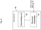
- Fig. 4 is a block diagram showing an example of a user equipment according to certain embodiments of the present invention.
- the user equipment 40 comprises a receiver/transmitter 41 and a determining unit 42.
- the receiver/transmitter 41 of the user equipment receives a first signaling message including information whether a target base station, to which handover of the user equipment is to be performed, supports assistance information.
- the receiver/transmitter 41 of the user equipment receives a second signaling message including information whether the source base station, to which the user equipment is connected, supports assistance information.
- the determining unit 42 of the user equipment determines based on the information included in the first signaling message and second signaling message,whether each of the source base station and the target base station supports assistance information.
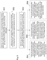
- Fig. 5 is a flowchart illustrating processing of the user equipment according to certain embodiments of the present invention.
- the user equipment receives a first signaling message including information whether a target base station, to which handover fo the user equipment is to be performed, supports assistance information.
- the user equipment receives a second signaling message including information whether a source base station, to which the user equipment is connected, supports assistance information.
- the user equipment determines, based on the information included in the first signaling message and the second signaling message, whether each of the source base station and the target base station supports assistance information.
- step S54 if it is determined in step S53 that both the source base station and the target base station support assistance information, the receiver/transmitter 41 of the user equipment 40 transmits assistance information to the target base station only if the assistance information differs from the assistance information transmitted previously to the source base station.
- step S55 if it is determined in step S53 that the source base station supports assistance information and the target base station does not support assistance information, the user equipment 40 inhibits transmitting assistance information when the user equipment is connected to the target base station until the user equipment is disconnected from the target base station.
- step S56 if it is determined in step S53 that the source base station does not support assistance information and the target base station supports assistance information, the receiver/transmitter 41 of the user equipment 40 transmits assistance information to the target base station when the user equipment is connected to the target base station.
- the first signaling message is sent at a time of connection reconfiguration after connection setup. Further, the second signaling message is transmitted at handover of the user equipment.
- each of the first and the second signaling message may be the same kind of message and may be a RRCConnectionReconfiguration message.
- the apparatus i.e. the user equipment or the base stations (or some other means) is configured to perform some function
- this is to be construed to be equivalent to a description stating that a (i.e. at least one) processor or corresponding circuitry, potentially in cooperation with computer program code stored in the memory of the respective apparatus, is configured to cause the apparatus to perform at least the thus mentioned function.
- a (i.e. at least one) processor or corresponding circuitry potentially in cooperation with computer program code stored in the memory of the respective apparatus, is configured to cause the apparatus to perform at least the thus mentioned function.
- function is to be construed to be equivalently implementable by specifically configured circuitry or means for performing the respective function (i.e. the expression "unit configured to” is construed to be equivalent to an expression such as "means for").
- respective functional blocks or elements according to above-described aspects can be implemented by any known means, either in hardware and/or software, respectively, if it is only adapted to perform the described functions of the respective parts.
- the mentioned method steps can be realized in individual functional blocks or by individual devices, or one or more of the method steps can be realized in a single functional block or by a single device.
- any method step is suitable to be implemented as software or by hardware without changing the idea of the present invention.
- Devices and means can be implemented as individual devices, but this does not exclude that they are implemented in a distributed fashion throughout the system, as long as the functionality of the device is preserved. Such and similar principles are to be considered as known to a skilled person.
- Software in the sense of the present description comprises software code as such comprising code means or portions or a computer program or a computer program product for performing the respective functions, as well as software (or a computer program or a computer program product) embodied on a tangible medium such as a computer-readable (storage) medium having stored thereon a respective data structure or code means/portions or embodied in a signal or in a chip, potentially during processing thereof.
Description
- The present invention relates to a signaling framework for assistance information. More particularly, the present invention relates to methods, apparatuses and a program relating to a signaling framework for assistance information, for example, in LTE.
- In the course of
Release 11 standardisation, signalling support for conveying assistance information from a user equipment (UE) is being discussed for multimedia broadcast-multicast service (MBMS), in-device coexistence (IDC) and enhancements for diverse data applications (EDDA). While the information needed to assist the network in case of MBMS, IDC and EDDA differ in nature, it would be beneficial to have a common framework for the reporting. Moreover, there may be such features in the future that the evolved NodeB (eNB) requires some assistance information from UE. Thus the same framework as in the present application can be used in such cases. - One of the problems related to the handling of assistance information is that the UE needs to know whether the eNB supports the signalling. Further, at handover, the overhead needs to be minimized. Another problem in this regard is that mobility across eNBs of different releases or having different set of functionalities must be supported.
- In this regard, in order to reduce overhead, in high speed uplink packet access (HSUPA), for the Scheduling Information (needed to assist the eNB in making scheduling decisions), it has been specified for the UE that if an enhanced dedicated channel (E-DCH) serving cell change occurs and if the new E-DCH serving cell was not part of the previous Serving E-DCH radio link set (RLS), the transmission of a Scheduling Information shall be triggered on that frequency, as described in document [1].
- In order to let the UE know whether the eNB supports the signalling, it has been proposed to add signalling to let the UE know whether assistance information are needed, but without addressing the mobility issue, as described in document [2].
- For mobility, it has been proposed that the UE should follow an order given by the target cell whether to report the assistance information after handover or not, as described in document [3]. Further, the options of UE receiving the confirmation of [assistance-information] context transfer from a target cell, and of UE always reporting assistance information after handover have been discussed in document [4].
- Moreover, for proximity indication, proximity reporting of CSG cells is enabled by network (NW) dedicated configuration to the UE (otherConfig in RRC specification [5]). UE will only report proximity of closed subscriber group (CSG) cells if configured by the NW. Proximity status is not transferred between cells and thus UE needs retransmit proximity at cell change if UE still considers proximity being valid.
-
- [1]: 3GPP TS 25.321, V11.0.0, December 2011.
- [2]: R2-121094, "MBMS service continuity and CSG cells", Nokia Siemens Networks, Nokia Corporation, 3GPP TSG-RAN WG2 Meeting #77bis, Jeju, Korea, 26 - 30 March 2012.
- [3]: R2-12156, "MBMS interest indication and RRC signaling details", Ericsson, ST-Ericsson, 3GPP TSG-RAN WG2 #77bis, Jeju, South Korea, March 26 - 30, 2012.
- [4]: R2-116292, "Further discussion on MBMS interest indication", LG Electronics Inc., 3GPP TSG-RAN WG2 #76, San Francisco, USA, November 14 - 18, 2011
- [5]: 3GPP TS 36.331, V10.5.0, March 2012
- Additional background art is reprensented by document
US7796557 B2 . - According to the present invention, there are provided methods, apparatuses and a program relating to a signaling framework for assistance information according to the appended independent claims. Further refinements are defined in the appended dependent claims.
- These and other objects, features, details and advantages will become more fully apparent from the following detailed description of embodiments of the present invention which is to be taken in conjunction with the appended drawings, in which:
-
Fig. 1 is a block diagram showing an example of a source base station and a target base station according to certain embodiments of the present invention -
Fig. 2 is a flowchart illustrating processing of the source base station according to certain embodiments of the present invention. -
Fig. 3 is a flowchart illustrating processing of the target base station according to certain embodiments of the present invention. -
Fig. 4 is a block diagram showing an example of a user equipment according to certain embodiments of the present invention. -
Fig. 5 is a flowchart illustrating processing of the user equipment according to certain embodiments of the present invention. - In the following, embodiments of the present invention are described by referring to general and specific examples of the embodiments, wherein the features of the embodiments can be freely combined with each other unless otherwise described. It is to be understood, however, that the description is given by way of example only, and that the described embodiments are by no means to be understood as limiting the present invention thereto.
- According to an embodiment of the present invention, the following aspects are proposed. It is noted that the following aspects can be combined in an arbitrary manner.
- According to a first aspect of the present invention, a dedicated signaling message is used to signal in a dedicated manner whether the current cell supports the assistance information at connection reconfiguration right after connection setup.
- Further, the dedicated signaling message is used to signal in a dedicated manner whether the target supports the assistance information at handover (HO).
- In a preferred option, the otherConfig information element in the RRC message RRCConnectionReconfiguration is used for such a dedicated signaling message.
- Hence, in view of the above, the signaling message is sent at connection reconfiguration right after connection setup and the signaling message is also sent at handover.
- On the basis of the above signaling messages, the UE can determine whether the source base station and the target base station understand the assistance information.
- According to a second aspect, if according to these received signaling messages the assistance information is understood both in the source and in the target base station, the UE needs to send only new information (i.e. information that has changed from the previous information sent) after HO.
- According to a third aspect, if according to these received signaling messages the assistance information is understood in the source but not in the target base station, the UE does not send assistance information as long as it remains in the target.
- According to a fourth aspect, if according to these received signaling messages the assistance information is not understood in the source but is understood in the target, the UE should send the assistance information as soon as it enters the target.
- During the handover preparation, the source provides the most up-to-date received UE assistance information to the target. Thus, the target can utilize that information if it supports it, even if the UE does not report again after the handover.
- This allows a common framework for the reporting of assistance information which efficiently supports mobility across eNBs of different releases or eNBs of having different support for assistance information while minimizing the uplink overhead.
-
Fig. 1 is a block diagram showing an example of a source base station and a target base station according to certain embodiments of the present invention. - As shown in
Fig. 1 , according to an exemplary embodiment of the present invention, thesource base station 10 comprises a transmitter/receiver 11, and acomposing unit 12. - The composing
unit 12 of thebase station 10, to which a user equipment is connected, i.e. thebase station 10 is a source base station, composes a first signaling message including information whether a target base station, to which handover of the user equipment is to be performed, supports assistance information and the transmitter/receiver 11 transmits the first signaling message to the user equipment. - Further, the composing
unit 12 of thesource base station 10, composes a second signaling message including information whether the source base station supports assistance information and the transmitter/receiver 11 transmits the second signaling message to the user equipment. - In this regard, it is noted that the order of the first and second signaling message is not limited to the above described order. That is, the second signaling message may be sent before the first signaling message is sent or vice versa.
- For example, the second signaling message is sent at a time of connection reconfiguration after connection setup, and the first signaling message is sent at handover of the user equipment.
- As also shown in
Fig. 1 , according to an exemplary embodiment of the present invention, thetarget base station 20 comprises a transmitter/receiver 21, and acomposing unit 22. - The composing
unit 22 of the base station, to which a handover of the user equipment is to be performed, i.e. thebase station 20 is a target base station, composes a signaling message including information whether the target base station supports assistance information. Further, the target base station transmits the signaling message via the transmitter/receiver 21 in the handover command to the source based station during handover. - Alternatively, according to another aspect, the target base station transmits the signaling message via the transmitter/
receiver 21 in the handover command to the user equipment after handover. -
Fig. 2 is a flowchart illustrating processing of the base station according to certain embodiments of the present invention. - According to an embodiment of the present invention, first, in a step S21, the base station, to which a user equipment is connected, which is a source base station in the present example, composes a first signaling message including information whether the target base station supports assistance information and then transmits the signaling message to the user equipment in a step S22.
- According to certain embodiments of the present invention, the source base station further composes, in a step S23, a second signaling message including information whether the source base station supports assistance information, and transmits the second signaling message to the user equipment in a step S24.
- According t further aspects of the present invention, the first signaling message is sent at handover of the user equipment, and the second signaling message is sent at a time of connection reconfiguration after connection setup.
- Further, each of the first and second signaling message is the same kind of message, and moreover, each of the first and second signaling message is a RRCConnectionReconfiguration message.
-
Fig. 3 is a flowchart illustrating processing of the base station according to certain embodiments of the present invention. - According to an embodiment of the present invention, first, in a step S31, the base station, to which handover the user equipment is to be performed, which is a target base station in the present example, composes a signaling message including information whether the target base station supports assistance information, and the base station transmits the signaling message to another base station, to which the user equipment is connected, in a step S32.
- Alternatively, according to another aspect, in a step S33, the target base station transmits the signaling message directly to the user equipment.
- According to certain embodiments of the present invention, the signaling message is transmitted at/after handover of the user equipment.
-
Fig. 4 is a block diagram showing an example of a user equipment according to certain embodiments of the present invention. - As shown in
Fig. 4 , according to an embodiment of the present invention, theuser equipment 40 comprises a receiver/transmitter 41 and a determiningunit 42. - The receiver/
transmitter 41 of the user equipment, receives a first signaling message including information whether a target base station, to which handover of the user equipment is to be performed, supports assistance information. - Further, the receiver/
transmitter 41 of the user equipment receives a second signaling message including information whether the source base station, to which the user equipment is connected, supports assistance information. - Then, the determining
unit 42 of the user equipment determines based on the information included in the first signaling message and second signaling message,whether each of the source base station and the target base station supports assistance information. -
Fig. 5 is a flowchart illustrating processing of the user equipment according to certain embodiments of the present invention. - According to an embodiment of the present invention, first, in a step S51, the user equipment, receives a first signaling message including information whether a target base station, to which handover fo the user equipment is to be performed, supports assistance information.
- Further, in a step S52, the user equipment receives a second signaling message including information whether a source base station, to which the user equipment is connected, supports assistance information.
- Then, in a step S53, the user equipment determines, based on the information included in the first signaling message and the second signaling message, whether each of the source base station and the target base station supports assistance information.
- Then, in a step S54, if it is determined in step S53 that both the source base station and the target base station support assistance information, the recevier/
transmitter 41 of theuser equipment 40 transmits assistance information to the target base station only if the assistance information differs from the assistance information transmitted previously to the source base station. - Further, in a step S55, if it is determined in step S53 that the source base station supports assistance information and the target base station does not support assistance information, the
user equipment 40 inhibits transmitting assistance information when the user equipment is connected to the target base station until the user equipment is disconnected from the target base station. - Moreover, in a step S56, if it is determined in step S53 that the source base station does not support assistance information and the target base station supports assistance information, the receiver/
transmitter 41 of theuser equipment 40 transmits assistance information to the target base station when the user equipment is connected to the target base station. - According to certain embodiment of the present invention, the first signaling message is sent at a time of connection reconfiguration after connection setup. Further, the second signaling message is transmitted at handover of the user equipment.
- Further, according to certain embodiments of the present invention, each of the first and the second signaling message may be the same kind of message and may be a RRCConnectionReconfiguration message.
- In the foregoing exemplary description of the user equipment and the base stations, only the units that are relevant for understanding the principles of the invention have been described using functional blocks. The user equipment and the base stations may comprise further units that are necessary for its respective operation. However, a description of these units is omitted in this specification. The arrangement of the functional blocks of the devices is not construed to limit the invention, and the functions may be performed by one block or further split into sub-blocks.
- When in the foregoing description it is stated that the apparatus, i.e. the user equipment or the base stations (or some other means) is configured to perform some function, this is to be construed to be equivalent to a description stating that a (i.e. at least one) processor or corresponding circuitry, potentially in cooperation with computer program code stored in the memory of the respective apparatus, is configured to cause the apparatus to perform at least the thus mentioned function. Also, such function is to be construed to be equivalently implementable by specifically configured circuitry or means for performing the respective function (i.e. the expression "unit configured to" is construed to be equivalent to an expression such as "means for").
- For the purpose of the present invention as described herein above, it should be noted that
- method steps likely to be implemented as software code portions and being run using a processor at a network control element or terminal (as examples of devices, apparatuses and/or modules thereof, or as examples of entities including apparatuses and/or modules therefore), are software code independent and can be specified using any known or future developed programming language as long as the functionality defined by the method steps is preserved;
- generally, any method step is suitable to be implemented as software or by hardware without changing the idea of the embodiments and its modification in terms of the functionality implemented;
- method steps and/or devices, units or means likely to be implemented as hardware components at the above-defined apparatuses, or any module(s) thereof, (e.g., devices carrying out the functions of the apparatuses according to the embodiments as described above) are hardware independent and can be implemented using any known or future developed hardware technology or any hybrids of these, such as MOS (Metal Oxide Semiconductor), CMOS (Complementary MOS), BiMOS (Bipolar MOS), BiCMOS (Bipolar CMOS), ECL (Emitter Coupled Logic), TTL (Transistor-Transistor Logic), etc., using for example ASIC (Application Specific IC (Integrated Circuit)) components, FPGA (Field-programmable Gate Arrays) components, CPLD (Complex Programmable Logic Device) components or DSP (Digital Signal Processor) components;
- devices, units or means (e.g. the above-defined apparatuses and user equipments/base stations, or any one of their respective units/means) can be implemented as individual devices, units or means, but this does not exclude that they are implemented in a distributed fashion throughout the system, as long as the functionality of the device, unit or means is preserved;
- an apparatus may be represented by a semiconductor chip, a chipset, or a (hardware) module comprising such chip or chipset; this, however, does not exclude the possibility that a functionality of an apparatus or module, instead of being hardware implemented, be implemented as software in a (software) module such as a computer program or a computer program product comprising executable software code portions for execution/being run on a processor;
- a device may be regarded as an apparatus or as an assembly of more than one apparatus, whether functionally in cooperation with each other or functionally independently of each other but in a same device housing, for example.
- In general, it is to be noted that respective functional blocks or elements according to above-described aspects can be implemented by any known means, either in hardware and/or software, respectively, if it is only adapted to perform the described functions of the respective parts. The mentioned method steps can be realized in individual functional blocks or by individual devices, or one or more of the method steps can be realized in a single functional block or by a single device.
- Generally, any method step is suitable to be implemented as software or by hardware without changing the idea of the present invention. Devices and means can be implemented as individual devices, but this does not exclude that they are implemented in a distributed fashion throughout the system, as long as the functionality of the device is preserved. Such and similar principles are to be considered as known to a skilled person.
- Software in the sense of the present description comprises software code as such comprising code means or portions or a computer program or a computer program product for performing the respective functions, as well as software (or a computer program or a computer program product) embodied on a tangible medium such as a computer-readable (storage) medium having stored thereon a respective data structure or code means/portions or embodied in a signal or in a chip, potentially during processing thereof.
- It is noted that the embodiments and general and specific examples described above are provided for illustrative purposes only and are in no way intended that the present invention is restricted thereto. Rather, it is the intention that all variations and modifications which fall within the scope of the appended claims are covered.
Claims (12)
- A method, comprising,composing, at a target base station (20), to which handover of a user equipment is to be performed, a first signaling message including information whether the target base station (20) supports reception of assistance information from a user equipment, wherein the assistance information is used to assist a long term evolution network for at least one of multimedia broadcast multicast service, in-device coexistence and enhancement for diverse data applications,transmitting, at the target base station (20), the first signaling message to a source base station (10) to which the user equipment is connected, andwhen the source base station (10) does not support reception of assistance information from the user equipment and the target base station (20) supports reception of assistance information from the user equipment, receiving, by the target base station (20), assistance information from the user equipment when the user equipment is connected to the target base station (20).
- The method according to claim 1, wherein the first signaling message is sent at handover of the user equipment.
- A method, comprisingreceiving, at a user equipment, a first signaling message including information whether a target base station (20), to which handover of the user equipment is to be performed supports reception of assistance information from a user equipment, wherein the assistance information is used to assist a long term evolution network for at least one of multimedia broadcast multicast service, in-device coexistence and enhancement for diverse data applications,receiving, at the user equipment, a second signaling message including information whether a source base station (10), to which the user equipment is connected, supports reception of assistance information from the user equipment, anddetermining, at the user equipment, based on the information included in the first signaling message and the second signaling message, whether each of the source base station (10) and the target base station (20) supports reception of assistance information from the user equipment; andwhen the source base station (10) does not support reception of assistance information from the user equipment and the target base station (20) supports reception of assistance information from the user equipment, transmitting, by the user equipment, assistance information to the target base station (20) when the user equipment is connected to the target base station (20).
- The method according to claim 3, wherein,when both the source base station (10) and the target base station (20) support reception of assistance information from the user equipment,transmitting, by the user equipment, assistance information to the target base station (20) only if assistance information differs from the assistance information transmitted previously to the source base station.
- The method according to claim 3, wherein,when the source base station supports reception of assistance information from the user equipment and the target base station does not support reception of assistance information from the user equipment,inhibiting transmitting assistance information when the user equipment is connected to the target base station (20) until the user equipment is disconnected from the target base station (20).
- A base station to which handover of a user equipment is to be performed such that it is a target base station (20), comprising,a composing unit configured to compose a first signaling message including information whether the target base station (20) supports reception of assistance information from a user equipment, wherein the assistance information is used to assist a long term evolution network for at least one of multimedia broadcast multicast service, in-device coexistence and enhancement for diverse data applications,a transmitter configured to transmit the first signaling message to a source base station (10) to which the user equipment is connected, andwhen the source base station (10) does not support reception of assistance information from the user equipment and the target base station (20 supports reception of assistance information from the user equipment, a receiver configured to receive assistance information from the user equipment when the user equipment is connected to the target base station (20).
- The base station according to claim 6, wherein the first signaling message is sent at handover of the user equipment.
- The base station according to claim 6 or 7, wherein the first signaling message is a RRCConnectionReconfiguration message.
- A user equipment, comprising
a receiver/transmitter configured to:receive a first signaling message including information whether a target base station (20), to which handover of the user equipment is to be performed supports reception of assistance information from the user equipment, wherein the assistance information is used to assist a long term evolution network for at least one of multimedia broadcast multicast service, in-device coexistence and enhancement for diverse data applications, furtherreceive a second signaling message including information whether a source base station (10), to which the user equipment is connected, supports reception of assistance information from the user equipment, anda determining unit configured to determine, based on the information included in the first signaling message and the second signaling message, whether each of the source base station (10) and the target base station (20) supports reception of assistance information from the user equipment;the receiver/transmitter further configured to:
when the source base station (10) does not support reception of assistance information from the user equipment and the target base station (20) supports reception of assistance information from the user equipment, transmit, by the user equipment, assistance information to the target base station (20) when the user equipment is connected to the target base station (20).. - The user equipment according to claim 9, wherein,when both the source base station (10) and the target base station (20) support reception of assistance information from the user equipment,the receiver/transmitter being further configured to:
transmit assistance information to the target base station (20) only if the assistance information differs from assistance information transmitted previously to the source base station (10). - The user equipment according to claim 9, wherein,when the source base station (10) supports reception of assistance information from the user equipment and the target base station (20) does not support reception of assistance information from the user equipment,the receiver/transmitter being further configured to:
inhibit transmitting assistance information when the user equipment is connected to the target base station (20) until the user equipment is disconnected from the target base station (20). - A computer program product comprising instructions to cause a base station to execute the steps of the method according to claims 1 to 2 or a user equipment to execute the steps of the method according to claims 3 to 5.
Applications Claiming Priority (1)
| Application Number | Priority Date | Filing Date | Title |
|---|---|---|---|
| PCT/EP2012/058940 WO2013170878A1 (en) | 2012-05-14 | 2012-05-14 | Signaling framework for assistance information |
Publications (2)
| Publication Number | Publication Date |
|---|---|
| EP2850874A1 EP2850874A1 (en) | 2015-03-25 |
| EP2850874B1 true EP2850874B1 (en) | 2021-03-24 |
Family
ID=46085623
Family Applications (1)
| Application Number | Title | Priority Date | Filing Date |
|---|---|---|---|
| EP12721284.3A Active EP2850874B1 (en) | 2012-05-14 | 2012-05-14 | Signaling framework for assistance information |
Country Status (7)
| Country | Link |
|---|---|
| US (1) | US9681340B2 (en) |
| EP (1) | EP2850874B1 (en) |
| KR (1) | KR101852994B1 (en) |
| CN (1) | CN104303547B (en) |
| ES (1) | ES2869852T3 (en) |
| PT (1) | PT2850874T (en) |
| WO (1) | WO2013170878A1 (en) |
Families Citing this family (4)
| Publication number | Priority date | Publication date | Assignee | Title |
|---|---|---|---|---|
| CN103582154B (en) * | 2012-08-02 | 2017-09-08 | 中国移动通信集团公司 | A kind of implementation method of discontinuous reception and base station |
| CN103582040B (en) * | 2012-08-06 | 2016-12-21 | 电信科学技术研究院 | A kind of information transferring method and device thereof |
| EP3721654A1 (en) * | 2017-12-07 | 2020-10-14 | Sony Corporation | Electronic device, infrastructure equipment and methods |
| CN111836379B (en) * | 2019-08-15 | 2023-10-27 | 维沃移动通信有限公司 | Auxiliary information reporting method, configuration method, terminal and network equipment |
Family Cites Families (13)
| Publication number | Priority date | Publication date | Assignee | Title |
|---|---|---|---|---|
| EP1712096B1 (en) * | 2004-01-05 | 2012-11-28 | Research In Motion Limited | Methods and apparatus for the communication of network capability information over a traffic channel |
| KR100893860B1 (en) * | 2004-06-10 | 2009-04-20 | 엘지전자 주식회사 | Method for Handover and Resuem Communication in Failing Handover applying to Broadband Wireless Access System |
| CN100502579C (en) * | 2006-03-22 | 2009-06-17 | 华为技术有限公司 | Method and system for realizing resource consistency process in wireless communication system |
| EP2031921A1 (en) * | 2007-08-14 | 2009-03-04 | Alcatel Lucent | Apparatus and method for handling mobile terminal capability informanion |
| KR101174059B1 (en) | 2008-12-19 | 2012-08-16 | 한국전자통신연구원 | Handover method for supporting Mobile IPTV services in mobile network |
| CN101820652B (en) * | 2009-02-26 | 2014-12-10 | 中兴通讯股份有限公司 | Acquisition method of data information and base station |
| KR101595983B1 (en) | 2009-04-28 | 2016-02-22 | 한국전자통신연구원 | Method of performing handover in multi carrier wireless access system |
| GB2472792A (en) * | 2009-08-17 | 2011-02-23 | Nec Corp | Measurement reporting in a mobile communications system |
| KR101674221B1 (en) * | 2010-01-28 | 2016-11-09 | 엘지전자 주식회사 | Apparatus and method of reporting logged measurement in wireless communication system |
| CN102238659B (en) * | 2010-04-29 | 2014-10-08 | 华为技术有限公司 | Base station switching processing method and base station equipment |
| JP4730475B1 (en) * | 2010-08-10 | 2011-07-20 | 株式会社安川電機 | Rotating electric machine, wind power generation system, and method of manufacturing rotating electric machine |
| CN103947249B (en) * | 2011-09-30 | 2018-04-27 | 英特尔公司 | The method that internet service is simultaneously transmitted by multiple wireless networks |
| US8750181B2 (en) * | 2012-05-14 | 2014-06-10 | Blackberry Limited | Maintaining MBMS continuity |
-
2012
- 2012-05-14 EP EP12721284.3A patent/EP2850874B1/en active Active
- 2012-05-14 CN CN201280073166.5A patent/CN104303547B/en active Active
- 2012-05-14 ES ES12721284T patent/ES2869852T3/en active Active
- 2012-05-14 WO PCT/EP2012/058940 patent/WO2013170878A1/en active Application Filing
- 2012-05-14 KR KR1020147035212A patent/KR101852994B1/en active IP Right Grant
- 2012-05-14 PT PT127212843T patent/PT2850874T/en unknown
- 2012-05-14 US US14/400,854 patent/US9681340B2/en active Active
Non-Patent Citations (1)
| Title |
|---|
| None * |
Also Published As
| Publication number | Publication date |
|---|---|
| ES2869852T3 (en) | 2021-10-26 |
| CN104303547B (en) | 2019-05-03 |
| KR20150009594A (en) | 2015-01-26 |
| US9681340B2 (en) | 2017-06-13 |
| CN104303547A (en) | 2015-01-21 |
| KR101852994B1 (en) | 2018-04-30 |
| US20150172969A1 (en) | 2015-06-18 |
| WO2013170878A1 (en) | 2013-11-21 |
| PT2850874T (en) | 2021-05-05 |
| EP2850874A1 (en) | 2015-03-25 |
Similar Documents
| Publication | Publication Date | Title |
|---|---|---|
| US10631270B2 (en) | Methods and nodes for setting values of system parameters used in a wireless communication system | |
| US11153884B2 (en) | Method and devices for transmitting system information from terminal device | |
| EP2276275B1 (en) | Method of handling multimedia broadcast multicast service data reception on multiple component carriers | |
| US10334660B2 (en) | Signalling about on-going and starting broadcast-service sessions on other frequency carriers | |
| US20140161102A1 (en) | Methods, Apparatuses, Related Computer Program Product And Data Structure For Deciding On A Signaling Scheme For Handover | |
| US20130028166A1 (en) | Mobile Wireless Communication System, Access Gateway, Wireless Base Station, And Mobile Wireless Communication Control Method | |
| JP2023505521A (en) | Mobile IAB node-based TAU method | |
| US8805318B2 (en) | Method of handling data transmission associated with natural disaster notification in a wireless communication system and related apparatus | |
| KR20130020768A (en) | Method for supporting enhanced multimedia broadcast multicast service (embms), method and device for sending mbms control channel (mcch) modification notice | |
| EP2850874B1 (en) | Signaling framework for assistance information | |
| US10880937B2 (en) | Method and devices for connecting a user equipment with a radio access network in a telecommunication network | |
| CA2955043A1 (en) | Handover method, handover apparatus and handover system | |
| EP2873265B1 (en) | Methods providing mbms service and traffic key coordination in a multi bmsc deployment and related broadcast provisioning systems and service centers | |
| US9119184B2 (en) | Method and system of transmitting a bearer resource request message from a UE to a MME for setting up an EPS bearer in a LTE network | |
| US20130258943A1 (en) | Method and system for managing mobile management entity (mme) in a telecommunication network | |
| EP3013102B1 (en) | Method of handling serving cell becoming barred status, base station using the same, and user equipment using the same | |
| US10194323B2 (en) | Wireless base station, core network device, wireless communication system, and wireless communication method | |
| WO2023193240A1 (en) | Methods and apparatuses for a handover preparation in a l2 u2n relay case | |
| WO2019081032A1 (en) | Method and apparatus for selecting the network access type (3gpp or non-3gpp) when making mobile terminated short message service (mt-sms) delivery over non-access stratum (nas) in 5g communications systems | |
| KR20130048148A (en) | Terminal and communication method thereof |
Legal Events
| Date | Code | Title | Description |
|---|---|---|---|
| PUAI | Public reference made under article 153(3) epc to a published international application that has entered the european phase |
Free format text: ORIGINAL CODE: 0009012 |
|
| 17P | Request for examination filed |
Effective date: 20141215 |
|
| AK | Designated contracting states |
Kind code of ref document: A1 Designated state(s): AL AT BE BG CH CY CZ DE DK EE ES FI FR GB GR HR HU IE IS IT LI LT LU LV MC MK MT NL NO PL PT RO RS SE SI SK SM TR |
|
| AX | Request for extension of the european patent |
Extension state: BA ME |
|
| DAX | Request for extension of the european patent (deleted) | ||
| STAA | Information on the status of an ep patent application or granted ep patent |
Free format text: STATUS: EXAMINATION IS IN PROGRESS |
|
| 17Q | First examination report despatched |
Effective date: 20170918 |
|
| RAP1 | Party data changed (applicant data changed or rights of an application transferred) |
Owner name: NOKIA SOLUTIONS AND NETWORKS OY |
|
| GRAP | Despatch of communication of intention to grant a patent |
Free format text: ORIGINAL CODE: EPIDOSNIGR1 |
|
| STAA | Information on the status of an ep patent application or granted ep patent |
Free format text: STATUS: GRANT OF PATENT IS INTENDED |
|
| INTG | Intention to grant announced |
Effective date: 20200504 |
|
| GRAJ | Information related to disapproval of communication of intention to grant by the applicant or resumption of examination proceedings by the epo deleted |
Free format text: ORIGINAL CODE: EPIDOSDIGR1 |
|
| STAA | Information on the status of an ep patent application or granted ep patent |
Free format text: STATUS: EXAMINATION IS IN PROGRESS |
|
| GRAP | Despatch of communication of intention to grant a patent |
Free format text: ORIGINAL CODE: EPIDOSNIGR1 |
|
| STAA | Information on the status of an ep patent application or granted ep patent |
Free format text: STATUS: GRANT OF PATENT IS INTENDED |
|
| INTC | Intention to grant announced (deleted) | ||
| INTG | Intention to grant announced |
Effective date: 20201019 |
|
| GRAS | Grant fee paid |
Free format text: ORIGINAL CODE: EPIDOSNIGR3 |
|
| GRAA | (expected) grant |
Free format text: ORIGINAL CODE: 0009210 |
|
| STAA | Information on the status of an ep patent application or granted ep patent |
Free format text: STATUS: THE PATENT HAS BEEN GRANTED |
|
| AK | Designated contracting states |
Kind code of ref document: B1 Designated state(s): AL AT BE BG CH CY CZ DE DK EE ES FI FR GB GR HR HU IE IS IT LI LT LU LV MC MK MT NL NO PL PT RO RS SE SI SK SM TR |
|
| REG | Reference to a national code |
Ref country code: GB Ref legal event code: FG4D |
|
| REG | Reference to a national code |
Ref country code: CH Ref legal event code: EP |
|
| REG | Reference to a national code |
Ref country code: DE Ref legal event code: R096 Ref document number: 602012074885 Country of ref document: DE |
|
| REG | Reference to a national code |
Ref country code: IE Ref legal event code: FG4D |
|
| REG | Reference to a national code |
Ref country code: AT Ref legal event code: REF Ref document number: 1375768 Country of ref document: AT Kind code of ref document: T Effective date: 20210415 |
|
| REG | Reference to a national code |
Ref country code: PT Ref legal event code: SC4A Ref document number: 2850874 Country of ref document: PT Date of ref document: 20210505 Kind code of ref document: T Free format text: AVAILABILITY OF NATIONAL TRANSLATION Effective date: 20210429 |
|
| REG | Reference to a national code |
Ref country code: NL Ref legal event code: FP |
|
| REG | Reference to a national code |
Ref country code: LT Ref legal event code: MG9D |
|
| PG25 | Lapsed in a contracting state [announced via postgrant information from national office to epo] |
Ref country code: BG Free format text: LAPSE BECAUSE OF FAILURE TO SUBMIT A TRANSLATION OF THE DESCRIPTION OR TO PAY THE FEE WITHIN THE PRESCRIBED TIME-LIMIT Effective date: 20210624 Ref country code: NO Free format text: LAPSE BECAUSE OF FAILURE TO SUBMIT A TRANSLATION OF THE DESCRIPTION OR TO PAY THE FEE WITHIN THE PRESCRIBED TIME-LIMIT Effective date: 20210624 Ref country code: FI Free format text: LAPSE BECAUSE OF FAILURE TO SUBMIT A TRANSLATION OF THE DESCRIPTION OR TO PAY THE FEE WITHIN THE PRESCRIBED TIME-LIMIT Effective date: 20210324 Ref country code: GR Free format text: LAPSE BECAUSE OF FAILURE TO SUBMIT A TRANSLATION OF THE DESCRIPTION OR TO PAY THE FEE WITHIN THE PRESCRIBED TIME-LIMIT Effective date: 20210625 Ref country code: HR Free format text: LAPSE BECAUSE OF FAILURE TO SUBMIT A TRANSLATION OF THE DESCRIPTION OR TO PAY THE FEE WITHIN THE PRESCRIBED TIME-LIMIT Effective date: 20210324 |
|
| PG25 | Lapsed in a contracting state [announced via postgrant information from national office to epo] |
Ref country code: LV Free format text: LAPSE BECAUSE OF FAILURE TO SUBMIT A TRANSLATION OF THE DESCRIPTION OR TO PAY THE FEE WITHIN THE PRESCRIBED TIME-LIMIT Effective date: 20210324 Ref country code: RS Free format text: LAPSE BECAUSE OF FAILURE TO SUBMIT A TRANSLATION OF THE DESCRIPTION OR TO PAY THE FEE WITHIN THE PRESCRIBED TIME-LIMIT Effective date: 20210324 Ref country code: SE Free format text: LAPSE BECAUSE OF FAILURE TO SUBMIT A TRANSLATION OF THE DESCRIPTION OR TO PAY THE FEE WITHIN THE PRESCRIBED TIME-LIMIT Effective date: 20210324 |
|
| REG | Reference to a national code |
Ref country code: AT Ref legal event code: MK05 Ref document number: 1375768 Country of ref document: AT Kind code of ref document: T Effective date: 20210324 |
|
| REG | Reference to a national code |
Ref country code: ES Ref legal event code: FG2A Ref document number: 2869852 Country of ref document: ES Kind code of ref document: T3 Effective date: 20211026 |
|
| PG25 | Lapsed in a contracting state [announced via postgrant information from national office to epo] |
Ref country code: EE Free format text: LAPSE BECAUSE OF FAILURE TO SUBMIT A TRANSLATION OF THE DESCRIPTION OR TO PAY THE FEE WITHIN THE PRESCRIBED TIME-LIMIT Effective date: 20210324 Ref country code: CZ Free format text: LAPSE BECAUSE OF FAILURE TO SUBMIT A TRANSLATION OF THE DESCRIPTION OR TO PAY THE FEE WITHIN THE PRESCRIBED TIME-LIMIT Effective date: 20210324 Ref country code: LT Free format text: LAPSE BECAUSE OF FAILURE TO SUBMIT A TRANSLATION OF THE DESCRIPTION OR TO PAY THE FEE WITHIN THE PRESCRIBED TIME-LIMIT Effective date: 20210324 Ref country code: SM Free format text: LAPSE BECAUSE OF FAILURE TO SUBMIT A TRANSLATION OF THE DESCRIPTION OR TO PAY THE FEE WITHIN THE PRESCRIBED TIME-LIMIT Effective date: 20210324 Ref country code: AT Free format text: LAPSE BECAUSE OF FAILURE TO SUBMIT A TRANSLATION OF THE DESCRIPTION OR TO PAY THE FEE WITHIN THE PRESCRIBED TIME-LIMIT Effective date: 20210324 |
|
| PG25 | Lapsed in a contracting state [announced via postgrant information from national office to epo] |
Ref country code: RO Free format text: LAPSE BECAUSE OF FAILURE TO SUBMIT A TRANSLATION OF THE DESCRIPTION OR TO PAY THE FEE WITHIN THE PRESCRIBED TIME-LIMIT Effective date: 20210324 Ref country code: IS Free format text: LAPSE BECAUSE OF FAILURE TO SUBMIT A TRANSLATION OF THE DESCRIPTION OR TO PAY THE FEE WITHIN THE PRESCRIBED TIME-LIMIT Effective date: 20210724 Ref country code: PL Free format text: LAPSE BECAUSE OF FAILURE TO SUBMIT A TRANSLATION OF THE DESCRIPTION OR TO PAY THE FEE WITHIN THE PRESCRIBED TIME-LIMIT Effective date: 20210324 Ref country code: SK Free format text: LAPSE BECAUSE OF FAILURE TO SUBMIT A TRANSLATION OF THE DESCRIPTION OR TO PAY THE FEE WITHIN THE PRESCRIBED TIME-LIMIT Effective date: 20210324 |
|
| REG | Reference to a national code |
Ref country code: CH Ref legal event code: PL |
|
| REG | Reference to a national code |
Ref country code: DE Ref legal event code: R097 Ref document number: 602012074885 Country of ref document: DE |
|
| PG25 | Lapsed in a contracting state [announced via postgrant information from national office to epo] |
Ref country code: DK Free format text: LAPSE BECAUSE OF FAILURE TO SUBMIT A TRANSLATION OF THE DESCRIPTION OR TO PAY THE FEE WITHIN THE PRESCRIBED TIME-LIMIT Effective date: 20210324 Ref country code: LU Free format text: LAPSE BECAUSE OF NON-PAYMENT OF DUE FEES Effective date: 20210514 Ref country code: LI Free format text: LAPSE BECAUSE OF NON-PAYMENT OF DUE FEES Effective date: 20210531 Ref country code: MC Free format text: LAPSE BECAUSE OF FAILURE TO SUBMIT A TRANSLATION OF THE DESCRIPTION OR TO PAY THE FEE WITHIN THE PRESCRIBED TIME-LIMIT Effective date: 20210324 Ref country code: AL Free format text: LAPSE BECAUSE OF FAILURE TO SUBMIT A TRANSLATION OF THE DESCRIPTION OR TO PAY THE FEE WITHIN THE PRESCRIBED TIME-LIMIT Effective date: 20210324 Ref country code: CH Free format text: LAPSE BECAUSE OF NON-PAYMENT OF DUE FEES Effective date: 20210531 |
|
| PLBE | No opposition filed within time limit |
Free format text: ORIGINAL CODE: 0009261 |
|
| STAA | Information on the status of an ep patent application or granted ep patent |
Free format text: STATUS: NO OPPOSITION FILED WITHIN TIME LIMIT |
|
| REG | Reference to a national code |
Ref country code: BE Ref legal event code: MM Effective date: 20210531 |
|
| PG25 | Lapsed in a contracting state [announced via postgrant information from national office to epo] |
Ref country code: SI Free format text: LAPSE BECAUSE OF FAILURE TO SUBMIT A TRANSLATION OF THE DESCRIPTION OR TO PAY THE FEE WITHIN THE PRESCRIBED TIME-LIMIT Effective date: 20210324 |
|
| 26N | No opposition filed |
Effective date: 20220104 |
|
| PG25 | Lapsed in a contracting state [announced via postgrant information from national office to epo] |
Ref country code: IE Free format text: LAPSE BECAUSE OF NON-PAYMENT OF DUE FEES Effective date: 20210514 |
|
| PG25 | Lapsed in a contracting state [announced via postgrant information from national office to epo] |
Ref country code: IS Free format text: LAPSE BECAUSE OF FAILURE TO SUBMIT A TRANSLATION OF THE DESCRIPTION OR TO PAY THE FEE WITHIN THE PRESCRIBED TIME-LIMIT Effective date: 20210724 |
|
| PG25 | Lapsed in a contracting state [announced via postgrant information from national office to epo] |
Ref country code: BE Free format text: LAPSE BECAUSE OF NON-PAYMENT OF DUE FEES Effective date: 20210531 |
|
| PG25 | Lapsed in a contracting state [announced via postgrant information from national office to epo] |
Ref country code: IT Free format text: LAPSE BECAUSE OF FAILURE TO SUBMIT A TRANSLATION OF THE DESCRIPTION OR TO PAY THE FEE WITHIN THE PRESCRIBED TIME-LIMIT Effective date: 20210324 |
|
| REG | Reference to a national code |
Ref country code: FR Ref legal event code: PLFP Year of fee payment: 12 |
|
| PG25 | Lapsed in a contracting state [announced via postgrant information from national office to epo] |
Ref country code: HU Free format text: LAPSE BECAUSE OF FAILURE TO SUBMIT A TRANSLATION OF THE DESCRIPTION OR TO PAY THE FEE WITHIN THE PRESCRIBED TIME-LIMIT; INVALID AB INITIO Effective date: 20120514 Ref country code: CY Free format text: LAPSE BECAUSE OF FAILURE TO SUBMIT A TRANSLATION OF THE DESCRIPTION OR TO PAY THE FEE WITHIN THE PRESCRIBED TIME-LIMIT Effective date: 20210324 |
|
| PGFP | Annual fee paid to national office [announced via postgrant information from national office to epo] |
Ref country code: GB Payment date: 20230330 Year of fee payment: 12 |
|
| PGFP | Annual fee paid to national office [announced via postgrant information from national office to epo] |
Ref country code: NL Payment date: 20230417 Year of fee payment: 12 |
|
| PGFP | Annual fee paid to national office [announced via postgrant information from national office to epo] |
Ref country code: PT Payment date: 20230516 Year of fee payment: 12 Ref country code: FR Payment date: 20230411 Year of fee payment: 12 Ref country code: ES Payment date: 20230605 Year of fee payment: 12 Ref country code: DE Payment date: 20230331 Year of fee payment: 12 |