EP2850721B1 - Spalttopf und magnetkupplungsanordnung mit einem solchen spalttopf - Google Patents
Spalttopf und magnetkupplungsanordnung mit einem solchen spalttopf Download PDFInfo
- Publication number
- EP2850721B1 EP2850721B1 EP13721783.2A EP13721783A EP2850721B1 EP 2850721 B1 EP2850721 B1 EP 2850721B1 EP 13721783 A EP13721783 A EP 13721783A EP 2850721 B1 EP2850721 B1 EP 2850721B1
- Authority
- EP
- European Patent Office
- Prior art keywords
- separating
- set forth
- shell
- inner shell
- tension elements
- Prior art date
- Legal status (The legal status is an assumption and is not a legal conclusion. Google has not performed a legal analysis and makes no representation as to the accuracy of the status listed.)
- Not-in-force
Links
- 230000008878 coupling Effects 0.000 claims description 12
- 238000010168 coupling process Methods 0.000 claims description 12
- 238000005859 coupling reaction Methods 0.000 claims description 12
- 239000000463 material Substances 0.000 claims description 8
- 238000013016 damping Methods 0.000 claims description 7
- 229910052751 metal Inorganic materials 0.000 claims description 4
- 239000002184 metal Substances 0.000 claims description 4
- 150000002739 metals Chemical class 0.000 claims description 4
- 239000004033 plastic Substances 0.000 claims description 3
- XLOMVQKBTHCTTD-UHFFFAOYSA-N Zinc monoxide Chemical compound [Zn]=O XLOMVQKBTHCTTD-UHFFFAOYSA-N 0.000 claims 2
- 229910010293 ceramic material Inorganic materials 0.000 claims 1
- 239000003733 fiber-reinforced composite Substances 0.000 claims 1
- 239000011787 zinc oxide Substances 0.000 claims 1
- 238000007789 sealing Methods 0.000 description 5
- 238000010276 construction Methods 0.000 description 4
- 239000002131 composite material Substances 0.000 description 2
- 239000000835 fiber Substances 0.000 description 2
- 238000009434 installation Methods 0.000 description 2
- 238000004519 manufacturing process Methods 0.000 description 2
- RVTZCBVAJQQJTK-UHFFFAOYSA-N oxygen(2-);zirconium(4+) Chemical compound [O-2].[O-2].[Zr+4] RVTZCBVAJQQJTK-UHFFFAOYSA-N 0.000 description 2
- 239000003566 sealing material Substances 0.000 description 2
- 229910001928 zirconium oxide Inorganic materials 0.000 description 2
- 238000005452 bending Methods 0.000 description 1
- 239000000919 ceramic Substances 0.000 description 1
- 230000008602 contraction Effects 0.000 description 1
- 230000001419 dependent effect Effects 0.000 description 1
- 230000000694 effects Effects 0.000 description 1
- 238000010292 electrical insulation Methods 0.000 description 1
- 230000002045 lasting effect Effects 0.000 description 1
- 230000036316 preload Effects 0.000 description 1
- 230000002028 premature Effects 0.000 description 1
- 239000002689 soil Substances 0.000 description 1
Images


Classifications
-
- H—ELECTRICITY
- H02—GENERATION; CONVERSION OR DISTRIBUTION OF ELECTRIC POWER
- H02K—DYNAMO-ELECTRIC MACHINES
- H02K5/00—Casings; Enclosures; Supports
- H02K5/04—Casings or enclosures characterised by the shape, form or construction thereof
- H02K5/12—Casings or enclosures characterised by the shape, form or construction thereof specially adapted for operating in liquid or gas
- H02K5/128—Casings or enclosures characterised by the shape, form or construction thereof specially adapted for operating in liquid or gas using air-gap sleeves or air-gap discs
-
- F—MECHANICAL ENGINEERING; LIGHTING; HEATING; WEAPONS; BLASTING
- F04—POSITIVE - DISPLACEMENT MACHINES FOR LIQUIDS; PUMPS FOR LIQUIDS OR ELASTIC FLUIDS
- F04D—NON-POSITIVE-DISPLACEMENT PUMPS
- F04D13/00—Pumping installations or systems
- F04D13/02—Units comprising pumps and their driving means
- F04D13/021—Units comprising pumps and their driving means containing a coupling
- F04D13/024—Units comprising pumps and their driving means containing a coupling a magnetic coupling
- F04D13/025—Details of the can separating the pump and drive area
Definitions
- the present invention relates to a containment shell, in particular for installation in a magnetic coupling arrangement, comprising a bottom, a cover flange, an inner shell and an outer shell surrounding the inner shell, which are both clamped between the bottom and the cover flange, and a magnetic coupling arrangement with such a containment shell.
- German Patent 103 61 378 B3 teaches a magnetic coupling assembly for transmitting a torque in which a weldment designed as a split pot is used, the one-piece cylindrical outer shell are provided with longitudinal notches and the inner shell is formed as a one-piece helical spring extending profile element.
- the technical function of the two above-mentioned gap pots is to complain that due to the outer shell additional eddy current losses occur and with speed-controlled drives the danger threatens to move in the natural frequency range of the outer shell. As a result, permanent vibrations are generated, which can lead to breakage of the individual, separated by gaps or notches longitudinal elements of the outer shell. In addition, no dry run is possible, since at high speeds through the outer shell eddy current losses occur, which can strongly heat the splitting head.
- the CA 1 129 469 shows a magnetic coupling assembly in which an existing slat shell is pressed together by individually releasable tension elements, wherein the tension elements are not integrated in the containment shell. From the DE 103 61 378 B3 a containment shell according to the preamble of claim 1 is known.
- the above-mentioned gap pots require increased manufacturing and assembly costs, due to the manufacture of the individual segments or the endless coil spring and the outer shell. As a seal of the segments or the endless coil spring sealing materials are required.
- the invention has for its object to provide a containment shell, in which the disadvantages known from the prior art avoided or at least greatly reduced.
- the containment shell which is particularly suitable for installation in a magnetic coupling arrangement, with a bottom with an outer bottom roof, a resilient bottom tension ring, a cover flange, an inner shell and an outer shell surrounding the inner shell, which are both clamped between the bottom and the cover flange, provided, wherein the outer shell consists of a plurality of individually releasable tension elements, wherein the bottom tension ring has clamping lips, which are resiliently biased against the outer bottom roof and wherein the outer bottom roof to the longitudinal axis of the containment shell a Angle ⁇ is less than 90 °.
- a broken tension element can be disassembled individually with the arrangement of the individually detachable tension elements of the outer shell of the containment shell according to the invention and replace and thus advantageously avoid great damage.
- the prestressed against the bottom roof arranged clamping lips contribute advantageously to accommodate changing loads of the present invention relieved by pressure connection cover flange - Segmentspalttopf - soil - bottom clamping ring and ensure a lasting fluid-tight connection. Any bending load is prevented or does not occur.
- the spring-elastic bottom tensioning ring as well as the tension elements are not in contact with the product and thus, inter alia, have a longer service life.
- the tension elements are designed as Switzerlandankerschrauben of high-strength metals.
- a break as previously discussed, however, is extremely rare to fear.
- the tension elements are designed as tie rod bolts made of high-strength light metals with high electrical resistivity. Also, this embodiment of the invention makes a break, as previously discussed, very rarely fear.
- the inner shell of the split pot is formed as a substantially cylindrical tube made of a material with high electrical resistivity. This advantageously results in an additional reduction of eddy current losses, which in individual cases can even drop to zero.
- the inner shell of the containment shell made of plastic, fiber composite or zirconium oxide.
- the containment shell is characterized in that a vibration damping device for the tension elements is arranged between the outer shell and the inner shell.
- the tension elements according to the invention are subject to a certain natural frequency. This is dependent on the internal pressure of the can and the biasing force of the screw connection of the tension elements and the screw material.
- the range between tension elements and the inner shell with a z. B. designed as a resilient element vibration damping device can be provided as a support. This can be advantageously arranged both over the entire pot area and only in certain areas.
- the vibration damping device is designed as a rubber band, which is advantageously a very cost-effective variant available.
- a containment shell according to claim 7 namely a magnetic coupling arrangement, which is characterized by a containment shell according to one of the claims.
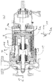
- Fig. 1 shows a split pot 101, mounted in a magnetic coupling assembly 200 of a pump 300, wherein on the left side of the Fig. 1 the hydraulics and on the right side the drive side of the pump is shown.
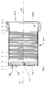
- Fig. 2 shows a split pot 101 according to the invention in section, wherein one recognizes the view into the interior of the split pot 101.
- Individual, an inner shell 108 forming segment rings 6 are connected to a holder ring 2 and a bottom 3 and an outer shell 110, which is formed from a plurality of individually releasable tension elements 8, here used as Switzerlandankerschrauben 114, to a cup-shaped structure, the containment shell 101 together ,
- the electrical insulation of the individual segment rings 6 against each other by sealing elements 11 according to Fig. 2y The centering of the holder ring 2, bottom 3 and segment rings 6 is represented by a shoulder, shown in FIG Fig. 2y , guaranteed.
- stud bolts 8 in terms of size and number is carried out according to the permissible pressure, temperature and screw material.
- the nuts 9 are tightened with a suitably defined torque and additionally biased by the resilient design of the bottom tension ring 4.
- Fig. 3 shows an alternative embodiment of the invention.
- a tubular component or tube 12 is used as the inner shell 108k.
- the arrangement of the outer shell 110 corresponds to that of the previously described embodiment.
- the tube 12 is advantageously made of a material having a high electrical resistivity.
- the material may be ceramic, eg zirconium oxide or fiber composite material or plastic, etc. When using these materials, the eddy current losses are reduced considerably. The efficiency of the entire unit increases, and the number of sealing elements can be advantageously reduced to a minimum. Furthermore, in this construction, no notch effects occur on the tubular component due to the pressure conditions prevailing in the interior of the containment shell.
- the inner shell 108k as a tube 12 against an inner shell of Segmentringen 6 (see embodiment according to Fig. 2 ) interchangeable.
- the studs 8 are subject to a certain natural frequency. This depends on the internal pressure of the segment splitting head and the preload force of the screw connection as well as the screw material. In order to shift this natural frequency into an uncritical range, or substantially increase it, the area between stud bolts 8 and segment rings 6 can be provided with a vibration damping device 116 designed as an elastic or resilient element (eg rubber). This can be arranged both over the entire pot area and only in certain areas.
- a vibration damping device 116 designed as an elastic or resilient element (eg rubber). This can be arranged both over the entire pot area and only in certain areas.
- FIG. 4 is an example shown in perspective half of a split pot 101, left from below, ie from the bottom 3 ago and right from above, so shown by the cover flange 1 ago.
- the inner shell 108 and the outer shell 110 are clearly visible.
- the externally arranged clamping screws 8 and locknuts 9 of the outer shell 110 are clearly visible.
Landscapes
- Engineering & Computer Science (AREA)
- Mechanical Engineering (AREA)
- General Engineering & Computer Science (AREA)
- Power Engineering (AREA)
- Pressure Vessels And Lids Thereof (AREA)
- Vibration Prevention Devices (AREA)
- Mechanical Operated Clutches (AREA)
Description
- Die vorliegende Erfindung betrifft einen Spalttopf, insbesondere zum Einbau in eine Magnetkupplungsanordnung, mit einem Boden, einem Deckelflansch, einer Innenhülle und einer die Innenhülle umgebenden Außenhülle, welche beide zwischen dem Boden und dem Deckelflansch eingespannt sind, sowie eine Magnetkupplungsanordnung mit einem solchen Spalttopf.
- Aus dem europäischen Patent
EP 0 372 838 B1 ist ein verlustarmes magnetisches Antriebssystem bekannt, bei welchem ein Spalttopf mit einer einstückigen zylindrischen Außenhülle eingesetzt wird, welche mit sich längs erstreckenden Schlitzen versehen ist. Lamellenartig geschichtete Ringe der Innenhülle werden über einen Deckelflansch gegen die Außenhülle verspannt werden - Das
deutsche Patent 103 61 378 B3 lehrt eine Magnetkupplungsanordnung zur Übertragung eines Drehmomentes, bei welcher ein als Schweißkonstruktion ausgebildeter Spalttopf zum Einsatz kommt, dessen einstückige zylindrische Außenhülle mit Längskerben versehen sind und dessen Innenhülle als einteiliges schraubenfederartig verlaufendes Profilelement ausgebildet ist. - An der technischen Funktion der beiden zuvor genannten Spalttöpfe ist zu bemängeln, dass durch die äußere Hülle zusätzliche Wirbelstromverluste auftreten und bei drehzahlgeregelten Antrieben die Gefahr droht, dass man sich im Eigenfrequenzbereich der äußeren Hülle bewegt. Dadurch werden Dauerschwingungen erzeugt, welche zum Bruch der einzelnen, durch Spalte oder Kerben voneinander getrennten Längselemente der Außenhülle führen können. Daneben ist kein Trockenlauf möglich, da bei hohen Drehzahlen durch die äußere Hülle Wirbelstromverluste auftreten, welche den Spaltkopf stark aufheizen können.
- Die
CA 1 129 469 zeigt eine Magnetkupplungsanordnung, bei der ein aus Lamellen bestehender Spalttopf durch einzeln lösbare Zugelemente zusammengepresst wird, wobei die Zugelemente nicht in dem Spalttopf integriert sind. Aus derDE 103 61 378 B3 ist ein Spalttopf gemäß dem Oberbegriff von Anspruch 1 bekannt. - Die oben genannten Spalttöpfe erfordern einen erhöhten Fertigungs- und Montageaufwand, aufgrund der Fertigung der einzelnen Segmente oder der Endlosschraubenfeder sowie der Außenhülle. Als Abdichtung der Segmente bzw. der Endlosschraubenfeder sind Dichtungsmaterialien erforderlich.
- Der Erfindung liegt die Aufgabe zugrunde, einen Spalttopf vorzuschlagen, bei dem die aus dem Stand der Technik bekannten Nachteile vermieden oder zumindest stark verringert werden.
- Die Aufgabe wird gelöst mit einem Spalttopf gemäß Anspruch 1. Hierbei ist der Spalttopf, der insbesondere zum Einbau in eine Magnetkupplungsanordnung geeignet ist, mit einem Boden mit einem äußeren Bodendach, einem federelastischen Bodenspannring, einem Deckelflansch, einer Innenhülle und einer die Innenhülle umgebenden Außenhülle, welche beide zwischen dem Boden und dem Deckelflansch eingespannt sind, versehen, wobei die Außenhülle aus einer Vielzahl von einzeln lösbaren Zugelementen besteht, wobei der Bodenspannring Spannlippen aufweist, welche gegen das äußere Bodendach federnd vorgespannt angeordnet sind und wobei das äußere Bodendach zur Längsachse des Spalttopfs einen Winkel α kleiner 90° einnimmt. Führte bei den aus dem Stand der Technik bekannten Spalttöpfen der Bruch eines einzigen Längselementes der Außenhülle sofort zum Totalschaden des Spalttopfs, wenn nicht weiterer Bauteile einer Magnetkupplungsanordnung, so lässt sich mit der Anordnung der einzeln lösbaren Zugelemente der Außenhülle des erfindungsgemäßen Spalttopfs ein gebrochenes Zugelement einzeln demontieren und ersetzen und damit vorteilhafterweise großer Schaden vermeiden. Die gegen das Bodendach vorgespannt angeordneten Spannlippen tragen in vorteilhafter Weise zur Aufnahme wechselnder Belastungen der erfindungsgemäß innendruckentlasteten Verbindung Deckelflansch - Segmentspalttopf - Boden - Bodenspannring bei und gewährleisten eine bleibende flüssigkeitsdichte Verbindung. Jegliche Biegebelastung wird verhindert bzw. tritt nicht auf. Hervorzuheben ist auch der Vorteil, dass bei dem erfindungsgemäßen Spalttopf der federelastische Bodenspannring sowie die Zugelemente nicht produktberührt sind und damit u. a. eine längere Standzeiten haben.
- In einer vorteilhaften Ausbildung der Erfindung sind die Zugelemente als Zugankerschrauben aus hochfesten Metallen ausgebildet. Allein aufgrund dieser erfindungsgemäßen Ausbildung ist ein Bruch, wie zuvor besprochen, allerdings äußerst selten zu befürchten.
- In noch einer vorteilhaften Ausbildung der Erfindung sind die Zugelemente als Zugankerschrauben aus hochfesten Leichtmetallen mit hohem spezifischem elektrischen Widerstand ausgebildet. Auch diese erfindungsgemäße Ausbildung lässt einen Bruch, wie zuvor besprochen, äußerst selten befürchten.
- In einer weiteren vorteilhaften Ausbildung der Erfindung ist die Innenhülle des Spalttopfs als im Wesentlichen zylindrisches Rohr aus einem Material mit hohem spezifischem elektrischem Widerstand ausgebildet. Dadurch ergibt sich vorteilhafterweise eine zusätzliche Reduzierung von Wirbelstromverlusten, die im Einzelfall sogar bis auf Null absinken können.
- In noch einer weiteren vorteilhaften Ausbildung der Erfindung besteht die Innenhülle des Spalttopfs aus Kunststoff, Faserverbundstoff oder Zirkonoxid.
- In einer anderen vorteilhaften Ausbildung der Erfindung ist der Spalttopf dadurch gekennzeichnet, dass zwischen der Außenhülle und der Innenhülle eine Schwingungsdämpfungseinrichtung für die Zugelemente angeordnet ist.
- Die erfindungsgemäßen Zugelemente unterliegen einer gewissen Eigenfrequenz. Diese ist abhängig vom Innendruck des Spalttopfes und der Vorspannkraft der Schraubenverbindung der Zugelemente sowie dem Schraubenwerkstoff. Um diese Eigenfrequenz in einen unkritischen Bereich zu verlagern, bzw. wesentlich zu erhöhen, kann der Bereich zwischen Zugelementen und der Innenhülle mit einer z. B. als federndes Element ausgebildeten Schwingungsdämpfungseinrichtung als Abstützung versehen werden. Diese kann vorteilhafterweise sowohl über den gesamten Topfbereich als auch nur in bestimmten Bereichen angeordnet werden.
- In einer weiteren vorteilhaften Ausbildung der Erfindung ist die Schwingungsdämpfungseinrichtung als Gummiband ausgebildet, womit vorteilhafterweise eine sehr kostengünstige Variante zur Verfügung steht.
- Die Aufgabe wird des Weiteren gelöst mit einem Spalttopf gemäß Anspruch 7, nämlich einer Magnetkupplungsanordnung, welche durch einen Spalttopf nach einem der Patentansprüche gekennzeichnet ist.
- Die Erfindung wird nachfolgend anhand eines bevorzugten Ausführungsbeispiels mit Hilfe der Zeichnung näher erläutert.
- Fig. 1
- zeigt schematisch ein Schnittbild einer Pumpe, in welcher der erfindungsgemäße Spalttopf angeordnet in einer Magnetkupplungsanordnung dargestellt ist.
- Fig. 2
- zeigt schematisch einen erfindungsgemäßen Spalttopf im Schnitt.
- Fig. 2y
- zeigt schematisch eine Einzelheit Y der
Fig. 2 stark vergrößert. - Fig. 2z
- zeigt schematisch eine Einzelheit Z der
Fig. 2 stark vergrößert. - Fig. 3
- zeigt schematisch eine weitere Variante des erfindungsgemäßen Spalttopfs im Schnitt, Blick in das Innere des Spalttopfs.
- Fig. 3x
- zeigt schematisch eine Einzelheit X der
Fig. 3 stark vergrößert. - Fig. 4
- zeigt beispielhaft eine perspektivisch dargestellte Hälfte eines Spalttopfes.
-
Fig. 1 zeigt einen Spalttopf 101, montiert in einer Magnetkupplungsanordnung 200 einer Pumpe 300, wobei auf der linken Seite derFig. 1 die Hydraulik und auf der rechten Seite die Antriebsseite der Pumpe dargestellt ist. -
Fig. 2 zeigt einen erfindungsgemäßen Spalttopf 101 im Schnitt, wobei man den Blick in das Innere des Spalttopfes 101 erkennt. Einzelne, eine Innenhülle 108 bildende Segmentringe 6 sind mit einem Halterring 2 und einem Boden 3 sowie einer Außenhülle 110, welche aus einer Vielzahl von einzeln lösbaren Zugelementen 8, hier als Zugankerschrauben 114 eingesetzt, gebildet ist, zu einem topfförmigen Gebilde, dem Spalttopf 101 zusammengesteckt. Die elektrische Isolierung der einzelnen Segmentringe 6 gegeneinander erfolgt durch Dichtungselemente 11 gemäßFig. 2y . Die Zentrierung von Halterring 2, Boden 3 und Segmentringen 6 wird durch einen Absatz, gezeigt inFig. 2y , gewährleistet. - Allein durch das Zusammenziehen der beschriebenen Bauteile entsteht noch keine innendruckbelastbare und flüssigkeitsdichte Verbindung. Diese wird erst durch den zusätzlichen Anbau eines Bodenspannringes 4, Flanschspannrings 5 sowie deren kraftschlüssige Verbindung durch Stiftschrauben 8 und Muttern 9 erreicht. Der Flanschspannring 5 wird in einem Flansch 1 geführt, der gleichzeitig die Verbindung zu einem Aufnahmebauteil darstellt. Zusätzlich werden die inneren Bauteile von einem Gewindering 7 gehalten und durch einen Nutring 10 (
Fig. 2z ) von innen her abgedichtet. Gut zu erkennen sind vom Bodenspannring 4 radial zur Längsachse 14 orientierte Spannlippen 4a, welche gegen das äußere Bodendach 3a federnd vorgespannt angeordnet sind. Sie drücken im dem der Längsachse 14 nahen Bereich federnd gegen das äußere Bodendach 3a, welches zur Längsachse 14 des Spalttopfs 1 einen Winkel α kleiner 90° einnimmt. Vorteilhafte Folge hiervon ist, dass die Spannlippen 4a, ausgenommen ihre radial nach innen weisenden Enden keine Berührung mit dem Bodendach 3a haben. Zwischen dem Bodendach 3a und den Spannlippen 4a ist also eine gewisse "Spannluft", mit den zuvor geschilderten Vorteilen. Diese Anordnung ist in der perspektivischen Darstellung gemäßFig. 4 auch leicht nachzuvollziehen. In der linken Hälfte des dort abgebildeten Spalttopfs 1 sind beispielhaft sechs sich vom Bodenspannring 4 radial zur Längsachse erstreckende Spannlippen 4a zu erkennen, welche auf das Bodendach 3a drücken. AuchFig. 1 zeigt die zur Längsachse 14 im Winkel α kleiner 90° abgewinkelt ausgebildete Form des Bodendachs 3a. - Die Auslegung der Stiftschrauben 8 hinsichtlich Größe und Anzahl erfolgt entsprechend dem zulässigen Druck, Temperatur und Schraubenwerkstoff. Um ein vorzeitiges Lockern der Schraubenverbindung zu verhindern bzw. eine ausreichende Vorspannkraft aufrecht zu erhalten, sind die Muttern 9 mit einem zweckmäßig definierten Drehmoment angezogen und zusätzlich durch die federnde Ausführung des Bodenspannrings 4 vorgespannt.
- Ausschlaggebend für die flüssigkeitsdichte Ausführung der einzelnen Segmente 6 ist eine ausreichende Flächenpressung des gewählten Dichtungsmaterials sowohl in drucklosem als auch in druckbeaufschlagtem Zustand des Segment-Spalttopfs. Im drucklosen Zustand wird dies alleine durch die Vorspannkraft der Schraube gewährleistet. Durch die Wahl der Flächenverhältnisse in der Konstruktion kommt es auch im druckbeaufschlagten Zustand zu keiner unzulässig hohen Flächenpressung auf die Dichtelemente.
-
Fig. 3 zeigt eine alternative Ausführung der Erfindung. Hier wird anstelle von einzelnen Segmentringen 6 der Innenhülle ein rohrartiges Bauteil oder Rohr 12 als Innenhülle 108k eingesetzt. Die Anordnung der Außenhülle 110 entspricht der des vorher erläuterten Ausführungsbeispiels. Das Rohr 12 ist vorteilhafterweise aus einem Werkstoff mit einem hohen spezifischen elektrischen Widerstand gefertigt. Der Werkstoff kann Keramik, z.B. Zirkonoxid oder Faserverbundwerkstoff oder Kunststoff etc. sein. Beim Einsatz dieser Materialien reduzieren sich die Wirbelstromverluste erheblich. Der Wirkungsgrad des gesamten Aggregates steigt, und die Anzahl der Dichtelemente lässt sich vorteilhafterweise auf ein Minimum reduzieren. Ferner kommt es bei dieser Konstruktion zu keinerlei Kerbwirkungen auf das rohrartige Bauteil durch die im Inneren des Spalttopfes herrschenden Druckverhältnisse. - Unter Beibehaltung der genannten vorhandenen Bauteile, d. h. ohne Änderung der Grundkonstruktion ist die Innenhülle 108k als Rohr 12 gegen eine Innenhülle aus Segmentringen 6 (siehe Ausführungsbeispiel gemäß
Fig. 2 ) austauschbar. Die Verbindung des Rohrs 12 zu dem Boden 3 und dem Haltering 2 erfolgt über einen Zwischenring 13 und gekammerte Dichtungselemente 11 (Fig. 3x ). Dies ermöglicht und vereinfacht eine keramikgerechte Konstruktion. - Die Stiftschrauben 8 unterliegen einer gewissen Eigenfrequenz. Diese ist abhängig vom Innendruck des Segment-Spaltkopfes und der Vorspannkraft der Schraubenverbindung sowie dem Schraubenwerkstoff. Um diese Eigenfrequenz in einen unkritischen Bereich zu verlagern, bzw. wesentlich zu erhöhen, kann der Bereich zwischen Stiftschrauben 8 und den Segmentringen 6 mit einer als elastisches bzw. federndes Element (z. B. Gummi) ausgebildeten Schwingungsdämpfungseinrichtung 116 als Abstützung versehen werden. Diese kann sowohl über den gesamten Topfbereich als auch nur in bestimmten Bereichen angeordnet werden.
- In
Fig. 4 ist beispielhaft eine perspektivisch dargestellte Hälfte eines Spalttopfes 101, links von unten, also vom Boden 3 her und rechts von oben, also vom Deckelflansch 1 her gezeigt. Man blickt jeweils hauptsächlich ins Innere des Spalttopfes 101, wobei die Innenhülle 108 und die Außenhülle 110 gut zu erkennen sind. Auch die außen angeordneten Spannschrauben 8 und Gegenmuttern 9 der Außenhülle 110 sind gut zu erkennen. -
- α
- Winkel
- 1
- Flansch
- 2
- Haltering
- 3
- Boden
- 3a
- Bodendach
- 3b
- Abstand
- 4
- Bodenspannring
- 4a
- Spannlippe
- 5
- Flanschspannring
- 6
- Segmentring
- 8
- Zugelement
- 9
- Mutter
- 10
- Nutring
- 11
- Dichtungselement
- 12
- Rohr
- 13
- Zwischenring
- 14
- Längsachse
- 101
- Spalttopf
- 108
- Innenhülle
- 108k
- Innenhülle
- 110
- Außenhülle
- 114
- Zugankerschraube
- 116
- Schwingungsdämpfungseinrichtung
- 200
- Magnetkupplungsanordnung
- 300
- Pumpe
Claims (8)
- Spalttopf (101), insbesondere zum Einbau in eine Magnetkupplungsanordnung (200), mit einem Boden (3) mit einem äußeren Bodendach (3a), einem federelastischen Bodenspannring (4), einem Deckelflansch (1), einer Innenhülle (108; 108k) und einer die Innenhülle (108; 108k) umgebenden Außenhülle (110), welche beide zwischen dem Boden (3) und dem Deckelflansch (1) eingespannt sind, dadurch gekennzeichnet, dass die Außenhülle (110) aus einer Vielzahl von einzeln lösbaren Zugelementen (8) besteht, dass der Bodenspannring (4) Spannlippen (4a) aufweist, welche gegen das äußere Bodendach (3a) federnd vorgespannt angeordnet sind und dass das äußere Bodendach (3a) zur Längsachse (14) des Spalttopfs (101) einen Winkel α kleiner 90° einnimmt.
- Spalttopf (101) nach Anspruch 1, dadurch gekennzeichnet, dass die Zugelemente als Zugankerschrauben (8) oder Stiftschrauben aus hochfesten Metallen ausgebildet sind.
- Spalttopf (101) nach Anspruch 1 oder 2, dadurch gekennzeichnet, dass die Zugelemente als Zugankerschrauben (8) oder Stiftschrauben aus Leichtmetallen mit einem hohen spezifischen elektrischen Widerstand ausgebildet sind.
- Spalttopf (101) nach Anspruch 1, 2 oder 3, dadurch gekennzeichnet, dass die Innenhülle (108k) aus einem im Wesentlichen zylindrischen Rohr (12) aus einem Material mit hohem spezifischem elektrischen Widerstand besteht.
- Spalttopf (101) nach Anspruch 4, dadurch gekennzeichnet, dass die Innenhülle (108k) aus Kunststoff, Faserverbundwerkstoff oder Keramik, vorzugsweise Zirkonoxid besteht.
- Spalttopf (101) nach einem der Ansprüche 1 bis 5, dadurch gekennzeichnet, dass zwischen der Außenhülle (110) und der Innenhülle (108) eine Schwingungsdämpfungseinrichtung (116) für die Zugelemente (8) angeordnet ist.
- Spalttopf (101) nach einem der vorhergehenden Ansprüche, dadurch gekennzeichnet, dass die Schwingungsdämpfungseinrichtung (116) als elastisches Element (116) ausgebildet ist.
- Magnetkupplungsanordnung (200), gekennzeichnet durch einen Spalttopf (101) nach einem der vorhergehenden Ansprüche.
Applications Claiming Priority (2)
| Application Number | Priority Date | Filing Date | Title |
|---|---|---|---|
| DE102012009654 | 2012-05-14 | ||
| PCT/EP2013/059826 WO2013171165A2 (de) | 2012-05-14 | 2013-05-13 | Spalttopf und magnetkupplungsanordnung mit einem solchen spalttopf |
Publications (2)
| Publication Number | Publication Date |
|---|---|
| EP2850721A2 EP2850721A2 (de) | 2015-03-25 |
| EP2850721B1 true EP2850721B1 (de) | 2016-07-13 |
Family
ID=48407588
Family Applications (1)
| Application Number | Title | Priority Date | Filing Date |
|---|---|---|---|
| EP13721783.2A Not-in-force EP2850721B1 (de) | 2012-05-14 | 2013-05-13 | Spalttopf und magnetkupplungsanordnung mit einem solchen spalttopf |
Country Status (2)
| Country | Link |
|---|---|
| EP (1) | EP2850721B1 (de) |
| WO (1) | WO2013171165A2 (de) |
Family Cites Families (3)
| Publication number | Priority date | Publication date | Assignee | Title |
|---|---|---|---|---|
| CA1129469A (en) * | 1980-05-02 | 1982-08-10 | Nova Scotia Research Foundation Corporation | Synchronous magnetic drive assembly with laminated barrier |
| CA1292763C (en) * | 1988-12-07 | 1991-12-03 | Patrick M. Taiani | Low loss magnetic drive system |
| DE10361378B3 (de) * | 2003-12-29 | 2005-09-22 | Karl Schmidt | Magnetkupplungsanordnung zur Übertragung eines Drehmomentes |
-
2013
- 2013-05-13 EP EP13721783.2A patent/EP2850721B1/de not_active Not-in-force
- 2013-05-13 WO PCT/EP2013/059826 patent/WO2013171165A2/de not_active Ceased
Also Published As
| Publication number | Publication date |
|---|---|
| EP2850721A2 (de) | 2015-03-25 |
| WO2013171165A2 (de) | 2013-11-21 |
| WO2013171165A3 (de) | 2014-02-27 |
Similar Documents
| Publication | Publication Date | Title |
|---|---|---|
| EP3189235B1 (de) | Exzenterschneckenpumpe | |
| DE202008000982U1 (de) | Gewindeeinsatz und Fahrzeugteil | |
| DE102012223317B4 (de) | Wälzlager | |
| EP3105483B1 (de) | Schelle | |
| AT510239A1 (de) | Einrichtung zur dämpfung von schwingungen in einem antriebsstrang | |
| DE102010034679A1 (de) | Dickstoffpumpe | |
| DE102012015504B4 (de) | Bauteil mit Einschraubabschnitt und damit ausgestattete Baugruppe | |
| EP3580463B1 (de) | Vorrichtung mit einem kolben, einem zylinder und wenigstens einem innenrohr und wenigstens einem aussenrohr | |
| EP2850721A2 (de) | Spalttopf und magnetkupplungsanordnung mit einem solchen spalttopf | |
| DE102008045571B4 (de) | Filterstützkorb | |
| DE102009044807B4 (de) | Spannringsatz | |
| DE102013206971B4 (de) | Hydraulikeinrichtung | |
| WO2013037345A1 (de) | Nehmerzylinder für ein hydraulisches ausrücksystem | |
| DE102014224653A1 (de) | Kugelgewindetrieb | |
| EP2818722B1 (de) | Kreiselpumpe | |
| DE202012008998U1 (de) | Arbeitszylinder | |
| EP2397716B1 (de) | Elastische kupplung | |
| EP1715200B1 (de) | Kugelgelenkverbindung | |
| WO2005028888A1 (de) | Lagerung zur aufnahme axialer belastungen | |
| EP3218620B1 (de) | Hydrobuchse sowie fahrzeug mit derartiger hydrobuchse | |
| DE102016215842B4 (de) | Kupplungsaggregat mit Betätigungssystem | |
| EP3842671B1 (de) | Wellendichtung, insbesondere radialwellendichtung, mit wenigstens einem dichtelement | |
| DE29807233U1 (de) | Knickschutz-Vorrichtung für eine Anschlußarmatur einer flexiblen Schlauchleitung | |
| EP3670948B1 (de) | Wälzlager mit radialem fangring zur begrenzung von radialen verformungen des wälzlagers | |
| EP1611387B1 (de) | Rohrkupplung |
Legal Events
| Date | Code | Title | Description |
|---|---|---|---|
| PUAI | Public reference made under article 153(3) epc to a published international application that has entered the european phase |
Free format text: ORIGINAL CODE: 0009012 |
|
| 17P | Request for examination filed |
Effective date: 20140612 |
|
| AK | Designated contracting states |
Kind code of ref document: A2 Designated state(s): AL AT BE BG CH CY CZ DE DK EE ES FI FR GB GR HR HU IE IS IT LI LT LU LV MC MK MT NL NO PL PT RO RS SE SI SK SM TR |
|
| AX | Request for extension of the european patent |
Extension state: BA ME |
|
| DAX | Request for extension of the european patent (deleted) | ||
| GRAP | Despatch of communication of intention to grant a patent |
Free format text: ORIGINAL CODE: EPIDOSNIGR1 |
|
| INTG | Intention to grant announced |
Effective date: 20160210 |
|
| RIN1 | Information on inventor provided before grant (corrected) |
Inventor name: KONRAD, JUERGEN Inventor name: RUSS, ANDREAS |
|
| GRAS | Grant fee paid |
Free format text: ORIGINAL CODE: EPIDOSNIGR3 |
|
| GRAA | (expected) grant |
Free format text: ORIGINAL CODE: 0009210 |
|
| AK | Designated contracting states |
Kind code of ref document: B1 Designated state(s): AL AT BE BG CH CY CZ DE DK EE ES FI FR GB GR HR HU IE IS IT LI LT LU LV MC MK MT NL NO PL PT RO RS SE SI SK SM TR |
|
| REG | Reference to a national code |
Ref country code: GB Ref legal event code: FG4D Free format text: NOT ENGLISH |
|
| REG | Reference to a national code |
Ref country code: AT Ref legal event code: REF Ref document number: 813000 Country of ref document: AT Kind code of ref document: T Effective date: 20160715 Ref country code: CH Ref legal event code: EP |
|
| REG | Reference to a national code |
Ref country code: IE Ref legal event code: FG4D Free format text: LANGUAGE OF EP DOCUMENT: GERMAN |
|
| REG | Reference to a national code |
Ref country code: DE Ref legal event code: R096 Ref document number: 502013003700 Country of ref document: DE |
|
| REG | Reference to a national code |
Ref country code: CH Ref legal event code: NV Representative=s name: PATENTANWAELTE SCHAAD, BALASS, MENZL AND PARTN, CH |
|
| REG | Reference to a national code |
Ref country code: LT Ref legal event code: MG4D |
|
| REG | Reference to a national code |
Ref country code: NL Ref legal event code: MP Effective date: 20160713 |
|
| PG25 | Lapsed in a contracting state [announced via postgrant information from national office to epo] |
Ref country code: HR Free format text: LAPSE BECAUSE OF FAILURE TO SUBMIT A TRANSLATION OF THE DESCRIPTION OR TO PAY THE FEE WITHIN THE PRESCRIBED TIME-LIMIT Effective date: 20160713 Ref country code: LT Free format text: LAPSE BECAUSE OF FAILURE TO SUBMIT A TRANSLATION OF THE DESCRIPTION OR TO PAY THE FEE WITHIN THE PRESCRIBED TIME-LIMIT Effective date: 20160713 Ref country code: IS Free format text: LAPSE BECAUSE OF FAILURE TO SUBMIT A TRANSLATION OF THE DESCRIPTION OR TO PAY THE FEE WITHIN THE PRESCRIBED TIME-LIMIT Effective date: 20161113 Ref country code: FI Free format text: LAPSE BECAUSE OF FAILURE TO SUBMIT A TRANSLATION OF THE DESCRIPTION OR TO PAY THE FEE WITHIN THE PRESCRIBED TIME-LIMIT Effective date: 20160713 Ref country code: NL Free format text: LAPSE BECAUSE OF FAILURE TO SUBMIT A TRANSLATION OF THE DESCRIPTION OR TO PAY THE FEE WITHIN THE PRESCRIBED TIME-LIMIT Effective date: 20160713 Ref country code: RS Free format text: LAPSE BECAUSE OF FAILURE TO SUBMIT A TRANSLATION OF THE DESCRIPTION OR TO PAY THE FEE WITHIN THE PRESCRIBED TIME-LIMIT Effective date: 20160713 Ref country code: IT Free format text: LAPSE BECAUSE OF FAILURE TO SUBMIT A TRANSLATION OF THE DESCRIPTION OR TO PAY THE FEE WITHIN THE PRESCRIBED TIME-LIMIT Effective date: 20160713 Ref country code: NO Free format text: LAPSE BECAUSE OF FAILURE TO SUBMIT A TRANSLATION OF THE DESCRIPTION OR TO PAY THE FEE WITHIN THE PRESCRIBED TIME-LIMIT Effective date: 20161013 |
|
| PG25 | Lapsed in a contracting state [announced via postgrant information from national office to epo] |
Ref country code: PT Free format text: LAPSE BECAUSE OF FAILURE TO SUBMIT A TRANSLATION OF THE DESCRIPTION OR TO PAY THE FEE WITHIN THE PRESCRIBED TIME-LIMIT Effective date: 20161114 Ref country code: ES Free format text: LAPSE BECAUSE OF FAILURE TO SUBMIT A TRANSLATION OF THE DESCRIPTION OR TO PAY THE FEE WITHIN THE PRESCRIBED TIME-LIMIT Effective date: 20160713 Ref country code: PL Free format text: LAPSE BECAUSE OF FAILURE TO SUBMIT A TRANSLATION OF THE DESCRIPTION OR TO PAY THE FEE WITHIN THE PRESCRIBED TIME-LIMIT Effective date: 20160713 Ref country code: GR Free format text: LAPSE BECAUSE OF FAILURE TO SUBMIT A TRANSLATION OF THE DESCRIPTION OR TO PAY THE FEE WITHIN THE PRESCRIBED TIME-LIMIT Effective date: 20161014 Ref country code: SE Free format text: LAPSE BECAUSE OF FAILURE TO SUBMIT A TRANSLATION OF THE DESCRIPTION OR TO PAY THE FEE WITHIN THE PRESCRIBED TIME-LIMIT Effective date: 20160713 Ref country code: LV Free format text: LAPSE BECAUSE OF FAILURE TO SUBMIT A TRANSLATION OF THE DESCRIPTION OR TO PAY THE FEE WITHIN THE PRESCRIBED TIME-LIMIT Effective date: 20160713 |
|
| REG | Reference to a national code |
Ref country code: DE Ref legal event code: R097 Ref document number: 502013003700 Country of ref document: DE |
|
| PG25 | Lapsed in a contracting state [announced via postgrant information from national office to epo] |
Ref country code: RO Free format text: LAPSE BECAUSE OF FAILURE TO SUBMIT A TRANSLATION OF THE DESCRIPTION OR TO PAY THE FEE WITHIN THE PRESCRIBED TIME-LIMIT Effective date: 20160713 Ref country code: EE Free format text: LAPSE BECAUSE OF FAILURE TO SUBMIT A TRANSLATION OF THE DESCRIPTION OR TO PAY THE FEE WITHIN THE PRESCRIBED TIME-LIMIT Effective date: 20160713 |
|
| PLBE | No opposition filed within time limit |
Free format text: ORIGINAL CODE: 0009261 |
|
| STAA | Information on the status of an ep patent application or granted ep patent |
Free format text: STATUS: NO OPPOSITION FILED WITHIN TIME LIMIT |
|
| REG | Reference to a national code |
Ref country code: FR Ref legal event code: PLFP Year of fee payment: 5 |
|
| PG25 | Lapsed in a contracting state [announced via postgrant information from national office to epo] |
Ref country code: SK Free format text: LAPSE BECAUSE OF FAILURE TO SUBMIT A TRANSLATION OF THE DESCRIPTION OR TO PAY THE FEE WITHIN THE PRESCRIBED TIME-LIMIT Effective date: 20160713 Ref country code: SM Free format text: LAPSE BECAUSE OF FAILURE TO SUBMIT A TRANSLATION OF THE DESCRIPTION OR TO PAY THE FEE WITHIN THE PRESCRIBED TIME-LIMIT Effective date: 20160713 Ref country code: BG Free format text: LAPSE BECAUSE OF FAILURE TO SUBMIT A TRANSLATION OF THE DESCRIPTION OR TO PAY THE FEE WITHIN THE PRESCRIBED TIME-LIMIT Effective date: 20161013 Ref country code: CZ Free format text: LAPSE BECAUSE OF FAILURE TO SUBMIT A TRANSLATION OF THE DESCRIPTION OR TO PAY THE FEE WITHIN THE PRESCRIBED TIME-LIMIT Effective date: 20160713 Ref country code: DK Free format text: LAPSE BECAUSE OF FAILURE TO SUBMIT A TRANSLATION OF THE DESCRIPTION OR TO PAY THE FEE WITHIN THE PRESCRIBED TIME-LIMIT Effective date: 20160713 |
|
| 26N | No opposition filed |
Effective date: 20170418 |
|
| PG25 | Lapsed in a contracting state [announced via postgrant information from national office to epo] |
Ref country code: LU Free format text: LAPSE BECAUSE OF NON-PAYMENT OF DUE FEES Effective date: 20170531 Ref country code: SI Free format text: LAPSE BECAUSE OF FAILURE TO SUBMIT A TRANSLATION OF THE DESCRIPTION OR TO PAY THE FEE WITHIN THE PRESCRIBED TIME-LIMIT Effective date: 20160713 |
|
| PG25 | Lapsed in a contracting state [announced via postgrant information from national office to epo] |
Ref country code: MC Free format text: LAPSE BECAUSE OF FAILURE TO SUBMIT A TRANSLATION OF THE DESCRIPTION OR TO PAY THE FEE WITHIN THE PRESCRIBED TIME-LIMIT Effective date: 20160713 |
|
| REG | Reference to a national code |
Ref country code: IE Ref legal event code: MM4A |
|
| PG25 | Lapsed in a contracting state [announced via postgrant information from national office to epo] |
Ref country code: LU Free format text: LAPSE BECAUSE OF NON-PAYMENT OF DUE FEES Effective date: 20170513 |
|
| REG | Reference to a national code |
Ref country code: BE Ref legal event code: MM Effective date: 20170531 |
|
| PG25 | Lapsed in a contracting state [announced via postgrant information from national office to epo] |
Ref country code: IE Free format text: LAPSE BECAUSE OF NON-PAYMENT OF DUE FEES Effective date: 20170513 |
|
| REG | Reference to a national code |
Ref country code: FR Ref legal event code: PLFP Year of fee payment: 6 |
|
| PG25 | Lapsed in a contracting state [announced via postgrant information from national office to epo] |
Ref country code: BE Free format text: LAPSE BECAUSE OF NON-PAYMENT OF DUE FEES Effective date: 20170531 |
|
| PG25 | Lapsed in a contracting state [announced via postgrant information from national office to epo] |
Ref country code: MT Free format text: LAPSE BECAUSE OF FAILURE TO SUBMIT A TRANSLATION OF THE DESCRIPTION OR TO PAY THE FEE WITHIN THE PRESCRIBED TIME-LIMIT Effective date: 20160713 |
|
| REG | Reference to a national code |
Ref country code: CH Ref legal event code: PFA Owner name: DICKOW PUMPEN GMBH AND CO. KG, DE Free format text: FORMER OWNER: DICKOW PUMPEN KG, DE |
|
| PG25 | Lapsed in a contracting state [announced via postgrant information from national office to epo] |
Ref country code: AL Free format text: LAPSE BECAUSE OF FAILURE TO SUBMIT A TRANSLATION OF THE DESCRIPTION OR TO PAY THE FEE WITHIN THE PRESCRIBED TIME-LIMIT Effective date: 20160713 |
|
| REG | Reference to a national code |
Ref country code: DE Ref legal event code: R082 Ref document number: 502013003700 Country of ref document: DE Representative=s name: FISCHER & KONNERTH PATENTANWAELTE PARTNERSCHAF, DE Ref country code: DE Ref legal event code: R081 Ref document number: 502013003700 Country of ref document: DE Owner name: DICKOW PUMPEN GMBH & CO. KG, DE Free format text: FORMER OWNER: DICKOW PUMPEN KG, 84478 WALDKRAIBURG, DE |
|
| REG | Reference to a national code |
Ref country code: AT Ref legal event code: HC Ref document number: 813000 Country of ref document: AT Kind code of ref document: T Owner name: DICKOW PUMPEN GMBH & CO. KG, DE Effective date: 20181120 |
|
| PG25 | Lapsed in a contracting state [announced via postgrant information from national office to epo] |
Ref country code: HU Free format text: LAPSE BECAUSE OF FAILURE TO SUBMIT A TRANSLATION OF THE DESCRIPTION OR TO PAY THE FEE WITHIN THE PRESCRIBED TIME-LIMIT; INVALID AB INITIO Effective date: 20130513 |
|
| PG25 | Lapsed in a contracting state [announced via postgrant information from national office to epo] |
Ref country code: CY Free format text: LAPSE BECAUSE OF FAILURE TO SUBMIT A TRANSLATION OF THE DESCRIPTION OR TO PAY THE FEE WITHIN THE PRESCRIBED TIME-LIMIT Effective date: 20160713 |
|
| PG25 | Lapsed in a contracting state [announced via postgrant information from national office to epo] |
Ref country code: MK Free format text: LAPSE BECAUSE OF FAILURE TO SUBMIT A TRANSLATION OF THE DESCRIPTION OR TO PAY THE FEE WITHIN THE PRESCRIBED TIME-LIMIT Effective date: 20160713 |
|
| PG25 | Lapsed in a contracting state [announced via postgrant information from national office to epo] |
Ref country code: TR Free format text: LAPSE BECAUSE OF FAILURE TO SUBMIT A TRANSLATION OF THE DESCRIPTION OR TO PAY THE FEE WITHIN THE PRESCRIBED TIME-LIMIT Effective date: 20160713 |
|
| PGFP | Annual fee paid to national office [announced via postgrant information from national office to epo] |
Ref country code: GB Payment date: 20220523 Year of fee payment: 10 Ref country code: FR Payment date: 20220523 Year of fee payment: 10 Ref country code: DE Payment date: 20220527 Year of fee payment: 10 |
|
| PGFP | Annual fee paid to national office [announced via postgrant information from national office to epo] |
Ref country code: CH Payment date: 20220523 Year of fee payment: 10 Ref country code: AT Payment date: 20220517 Year of fee payment: 10 |
|
| REG | Reference to a national code |
Ref country code: DE Ref legal event code: R082 Ref document number: 502013003700 Country of ref document: DE Representative=s name: KILIAN KILIAN & PARTNER MBB PATENTANWAELTE, DE |
|
| REG | Reference to a national code |
Ref country code: DE Ref legal event code: R119 Ref document number: 502013003700 Country of ref document: DE |
|
| REG | Reference to a national code |
Ref country code: CH Ref legal event code: PL |
|
| REG | Reference to a national code |
Ref country code: AT Ref legal event code: MM01 Ref document number: 813000 Country of ref document: AT Kind code of ref document: T Effective date: 20230513 |
|
| GBPC | Gb: european patent ceased through non-payment of renewal fee |
Effective date: 20230513 |
|
| PG25 | Lapsed in a contracting state [announced via postgrant information from national office to epo] |
Ref country code: LI Free format text: LAPSE BECAUSE OF NON-PAYMENT OF DUE FEES Effective date: 20230531 Ref country code: CH Free format text: LAPSE BECAUSE OF NON-PAYMENT OF DUE FEES Effective date: 20230531 Ref country code: AT Free format text: LAPSE BECAUSE OF NON-PAYMENT OF DUE FEES Effective date: 20230513 |
|
| PG25 | Lapsed in a contracting state [announced via postgrant information from national office to epo] |
Ref country code: DE Free format text: LAPSE BECAUSE OF NON-PAYMENT OF DUE FEES Effective date: 20231201 Ref country code: GB Free format text: LAPSE BECAUSE OF NON-PAYMENT OF DUE FEES Effective date: 20230513 |
|
| PG25 | Lapsed in a contracting state [announced via postgrant information from national office to epo] |
Ref country code: FR Free format text: LAPSE BECAUSE OF NON-PAYMENT OF DUE FEES Effective date: 20230531 |