EP2850315B1 - Spark plug extension - Google Patents
Spark plug extension Download PDFInfo
- Publication number
- EP2850315B1 EP2850315B1 EP13790028.8A EP13790028A EP2850315B1 EP 2850315 B1 EP2850315 B1 EP 2850315B1 EP 13790028 A EP13790028 A EP 13790028A EP 2850315 B1 EP2850315 B1 EP 2850315B1
- Authority
- EP
- European Patent Office
- Prior art keywords
- spark plug
- assembly
- extension body
- end portion
- ignition coil
- Prior art date
- Legal status (The legal status is an assumption and is not a legal conclusion. Google has not performed a legal analysis and makes no representation as to the accuracy of the status listed.)
- Active
Links
Images


Classifications
-
- F—MECHANICAL ENGINEERING; LIGHTING; HEATING; WEAPONS; BLASTING
- F02—COMBUSTION ENGINES; HOT-GAS OR COMBUSTION-PRODUCT ENGINE PLANTS
- F02P—IGNITION, OTHER THAN COMPRESSION IGNITION, FOR INTERNAL-COMBUSTION ENGINES; TESTING OF IGNITION TIMING IN COMPRESSION-IGNITION ENGINES
- F02P3/00—Other installations
- F02P3/02—Other installations having inductive energy storage, e.g. arrangements of induction coils
-
- H—ELECTRICITY
- H01—ELECTRIC ELEMENTS
- H01F—MAGNETS; INDUCTANCES; TRANSFORMERS; SELECTION OF MATERIALS FOR THEIR MAGNETIC PROPERTIES
- H01F38/00—Adaptations of transformers or inductances for specific applications or functions
- H01F38/12—Ignition, e.g. for IC engines
-
- H—ELECTRICITY
- H01—ELECTRIC ELEMENTS
- H01T—SPARK GAPS; OVERVOLTAGE ARRESTERS USING SPARK GAPS; SPARKING PLUGS; CORONA DEVICES; GENERATING IONS TO BE INTRODUCED INTO NON-ENCLOSED GASES
- H01T13/00—Sparking plugs
- H01T13/02—Details
- H01T13/04—Means providing electrical connection to sparking plugs
-
- H—ELECTRICITY
- H01—ELECTRIC ELEMENTS
- H01T—SPARK GAPS; OVERVOLTAGE ARRESTERS USING SPARK GAPS; SPARKING PLUGS; CORONA DEVICES; GENERATING IONS TO BE INTRODUCED INTO NON-ENCLOSED GASES
- H01T13/00—Sparking plugs
- H01T13/40—Sparking plugs structurally combined with other devices
- H01T13/44—Sparking plugs structurally combined with other devices with transformers, e.g. for high-frequency ignition
-
- Y—GENERAL TAGGING OF NEW TECHNOLOGICAL DEVELOPMENTS; GENERAL TAGGING OF CROSS-SECTIONAL TECHNOLOGIES SPANNING OVER SEVERAL SECTIONS OF THE IPC; TECHNICAL SUBJECTS COVERED BY FORMER USPC CROSS-REFERENCE ART COLLECTIONS [XRACs] AND DIGESTS
- Y10—TECHNICAL SUBJECTS COVERED BY FORMER USPC
- Y10T—TECHNICAL SUBJECTS COVERED BY FORMER US CLASSIFICATION
- Y10T29/00—Metal working
- Y10T29/49—Method of mechanical manufacture
- Y10T29/49229—Prime mover or fluid pump making
- Y10T29/49231—I.C. [internal combustion] engine making
Definitions
- the present invention relates to an ignition coil assembly for a spark ignited internal combustion engine comprising an ignition coil where said assembly has a main axis and is configured for insertion in a spark plug well.
- Internal combustion engines comprise spark plugs for initiating combustion driving the engine piston and require a spark to ignite the compressed fuel.
- an ignition coil transforms the battery's low voltage to high voltage needed to create an electric spark in the spark plugs to ignite the fuel.
- Common for all plugs is that they are arranged to be fitted into a well on the cylinder head piercing the wall of the combustion chamber so that the ignition terminal is brought into contact with the interior of the combustion cylinder.
- Direct ignition systems where the ignition coil is mounted directly above each spark plug, are known to be advantageous since they eliminate the need of spark-plug wires and reduces leakage current as well as it makes ignition timing-control easier. Such a system is disclosed in EP0987435 .
- These direct ignition systems are usually made up as one integrated assembly comprising both the spark plug as well as the ignition coil, whereby the spark plug is connected to the coil via an interconnecting extension body.
- the size (length) of the extension body in its turn is dependent on the dimensions of the motor.
- Spark ignited engines are sometimes designed with a vast distance (often at least 150 mm, sometimes as much as 500 mm) between the engine head and the internal combustion cylinder leading to that large spark plug constructions are needed in order for the ignition terminal to reach the cylinder. In some cases this is due to that the spark ignited engine originates from a converted diesel engine. As a diesel engine lacks spark plugs they are not designed to be serviced and the engine is therefore normally not adapted to promote easy access of any plug.
- US 2008/0271724 describes an ignition coil apparatus for an internal combustion engine.
- the apparatus is with a high voltage tower that holds a high voltage terminal in its interior, and a cylindrical plug boot that has electrical insulation and flexibility and is attached at its one end to the high voltage tower, where the plug boot may be installed on a main body of the internal combustion engine by being inserted into a bent plug hole.
- EP 0713005 A2 describes an ignition system for an internal combustion engine wherein insertion of a terminal into a sleeve from above a cap, with an upper portion of the sleeve fitted in a sleeve receiving portion of the cap, causes a ledge on an upper portion of the terminal to advance beyond a ledge of the cap made in rubber into a position lower than the ledge, whereby an upper side of the ledge engages the ledge to prevent the upward movement of the terminal and a lower side of the ledge is locked to an upper end surface of the sleeve to prevent the terminal from slipping of downwards, thereby completely positioning the terminal.
- US 5357233 discloses an ignition apparatus for an internal combustion engine for providing a peaked high voltage current from an ignition coil to a spark plug through a bendable extension device including a first portion extending from the ignition coil, a second portion adapted to be connected to the spark plug and an elastic member connecting the first member to the second member so that the first member moves elastically in relation to the second member.
- an ignition coil assembly according to the appended claim 1, wherein the assembly comprises an elongated and flexible extension body which comprises an upper end portion and a lower end portion and where said extension body is arranged to be transversally bendable in relation to a main axis so that the upper end portion and the lower end portion of the extension body may assume an angle in relation to each other between 0 - 360°.
- the extension body interconnects a spark plug receiving end portion and the ignition coil to each other. Thanks to that the extension body is transversally bendable in relation to the main axis, the spark plug receiving end portion and the ignition coil of the assembly may be configured to assume an angle in relation to each other.
- the extension body is made of a flexible material such as rubber. It is to be understood that the term "flexible” is to be interpreted as capable of being bent without breaking.
- an assembly which is very easy to handle and which may be configured to fit a large variety of engine types, having various dimensions of the well.
- the extension body the assembly can be adapted in length to a particular well, and due to the flexible property of the extension body, the ignition coil assembly can even be designed to fit deep wells (i.e. requiring a long extension body) without running into practical difficulties when removing/introducing the assembly due to limited space inside the motor compartment.
- an assembly body according to the invention may simply be bent (e.g. during removal of the assembly) and can thus be adapted to the space available around the well under the hood of the vehicle. Furthermore, it facilitates providing compact engine compartments.
- said ignition coil is detachably arranged within a first joining section at an upper end portion of the extension body.
- the spark plug is detachably arranged within a detachable spark plug boot which is removably mounted at a lower end portion of the extension body.
- said spark plug boot is made of a flexible and heat resistant material such as silicone rubber, arranged to tightly embrace the spark plug to provide an isolating layer and prevent leakage of high voltage current.
- the spark plug boot is arranged to be fitted within an adapter unit (a spark plug boot adapter) which in its turn is attached to a second joining section at the lower end portion of the extension body.
- the adapter unit is preferably made of a heat resistant and isolating material, such as ceramics or high temperature plastic, whereby there is achieved an efficient insulator between the spark plug and the second lowermost joining section of the assembly. Thanks to this aspect there is achieved the benefit that the soft and heat sensitive parts of the assembly, such as the extension body often being made of a resilient material such as rubber, are protected from the heat of the spark plug and are therefore also kept from destruction. An overheated rubber part could otherwise cause the assembly to break down which may result in difficulties during removal of the assembly or replacement of parts, and/or cause leakage of current.
- the spark plug boot is easy to detach from the spark plug adapter and at the same time is dimensioned with regards to its diameter to allow for a spark plug socket to reach the spark plug.
- Figs. 1 - 6 the ignition coil assembly is generally designated 1.
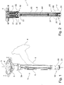
- Fig. 1 is shown a perspective view of an embodiment of an assembly 1 according to the invention, and
- Fig. 2 shows a cross section of the assembly according to line II in Fig. 1 .
- the main parts of the assembly 1 comprise a spark plug receiving end portion 10, an ignition coil 3 and an elongated extension body 6.
- the assembly 1 is configured for insertion in a well 90 of a cylinder head 9 (see Figs. 3a-b ) which is associated with an internal combustion engine.
- the spark plug receiving end portion 10 and the coil 3 are connected to each other by means of the elongated extension body 6 which comprises an inner, generally cylindrical, through bore 60 through which there is arranged an interconnecting member, for instance in the form of a flexible conductor device such as one or several cable/s 64 or a connecting spring, electrically connecting a spark plug 2 inserted into the spark plug receiving end portion 10, and said coil 3.
- an interconnecting member for instance in the form of a flexible conductor device such as one or several cable/s 64 or a connecting spring, electrically connecting a spark plug 2 inserted into the spark plug receiving end portion 10, and said coil 3.
- Any commercially available ignition cable can be used.
- At each end portion of the cable 64 there is preferably arranged connections which is intended for retaining an upper 22 and a lower 24 contact spring.
- Said contact springs 22, 24 safeguards electrical connection between the ignition coil 3 and a spark plug 2.
- the contact springs 22, 24 and the cable 64 may be replaced by one extended contact spring connecting the spark plug and the coil.
- the interconnecting member 64 is a flexible interconnecting conductor of suitable kind, and is not to be limited to cables or springs.
- the assembly 1 is generally cylindrical and has a main axis "A", and said elongated extension body 6 is arranged to be transversally bendable in relation to the main axis A so that the spark plug receiving end portion 10 and the ignition coil 3 may be configured to assume an angle ⁇ in relation to each other.
- the assembly 1 is shown in a bent configuration by means of dashed lines in Fig. 1 in which position the extension body 6 has been bent so that its upper end portion 62 and its lower end portion 65 have assumed an angle ⁇ in relation to each other.
- Theoretically said angle ⁇ may be between 0 - 360°, however it is most likely that it will lie be between 90 - 180°. Bending is achieved by means of said extension body 6 being made of a flexible, resilient material, which allows for e.g. bending the assembly 1 without breaking it.
- One suitable material for said extension body could be rubber.
- the ignition coil 3 comprising a core 31 and coils 32, is detachably arranged within a first joining section 63 located at the upper end portion 62 of the extension body 6, and is beneficially positioned inside an ignition coil casing 30.
- the ignition coil casing 30 is arranged to be attached onto the first joining section 63 by means of a coupling sleeve 34 being threaded, or attached in any other suitable way, onto the exterior of the extension body 6 and the coil casing 30 respectively, adjoining and retaining the two parts.
- said ignition coil casing 30 is provided with outer threading matching the inner threading of the coupling sleeve 34.
- the assembly 1 is seen to be provided with a spark plug 2 in Figs. 3a - b , where said spark plug 2 is releasably inserted into the spark plug receiving end portion 10 of the assembly 1.
- the spark plug 2 is detachably arranged within an spark plug boot 23 which is removably mounted onto a second joining section 66 at a lower end portion 65 of the extension body 6.
- the spark plug boot 23 is located within an adaptor unit 20 (also referred to as "spark plug casing" or "boot adapter”) which in its turn is attached to the second joining section 66 of the elongated extension body 6.
- Said boot adapter is preferably made of a material which is heat resistant and preferably an electrical insulator both in high-temperatures and in humid conditions.
- the spark plug boot 23 is detachable from the assembly 1, for instance by means of a snap-in mechanism and may thereby easily be replaced if desired. According to one embodiment the spark plug boot 23 is attached to the boot adapter 20 by means of a snap-in mechanism such that the spark plug boot 23 can be detached from the adaptor 20 regardless of whether the spark plug has gotten stuck to it: over time, silicone rubber can bond with the silicon ceramic of the spark plug, fusing the boot and the spark plug together so that the spark plug gets stuck.
- a snap-in mechanism such that the spark plug boot 23 can be detached from the adaptor 20 regardless of whether the spark plug has gotten stuck to it: over time, silicone rubber can bond with the silicon ceramic of the spark plug, fusing the boot and the spark plug together so that the spark plug gets stuck.
- the invention also relates to an embodiment where the ignition coil 3 is positioned directly adjacent to the ignition plug, and said elongated extension body 6 is connected to the ignition coil so as to form an extension of the assembly 1 to promote easy removing and/or introducing the ignition coil assembly from/into the motor.
- the diameter of the spark plug boot 23 is smaller than the diameter of the spark plug wrench so that it is still possible to remove/replace the spark plug if it should get stuck.
- the spark plug boot 23 is arranged to be removed and discarded together with the spark plug.
- the spark plug boot 23 is dimensioned to both being easily detachable from the adaptor unit 20 and to allow for a socket to reach the spark plug 2 properly.
- said spark plug boot 23 is made of a flexible, heat resistant and isolating material, such as silicone rubber, whereby there is achieved an efficient insulator between the spark plug 2 and the second joining section 66 of the extension body 6.
- the spark plug boot 23 is dimensioned to tightly embrace the spark plug thereby creating an efficient isolating layer and preventing leakage of high voltage current. Thanks to the spark plug boot 23 there is also achieved the advantage that the spark plug 2 is prevented from getting stuck to the adaptor unit 20 because the spark plug boot 23 creates a protecting layer which leads to facilitated detaching of the spark plug boot 23.
- a direct ignition assembly 1 according to the invention shown in Figs. 1 - 6 , is provided, and an spark plug 2 is fitted into the spark plug boot 23 at the lower end portion 65 of the assembly 1. Fitting into place of the plug 2 results in electrical connection with the coil 3 disposed above the plug 2, via said interconnecting member 64 (e.g. cable and/or spring).
- the assembly 1 is introduced into the well 90 of the cylinder head 9 so that the spark plug terminal is brought into contact with the interior of the combustion chamber. This operation is significantly facilitated by means of said extension body 6 being resilient and flexible since this allows for bending of the assembly 1 during that the lower end portion 65, comprising the spark plug terminal 2, is brought to a proper position for entering the well 90.
- an assembly 1 according to the invention will allow for easy and swift introduction even when the well 90 is deep and the assembly body is correspondingly elongated. Bending of the extension body 6 allows for firstly introducing the spark plug end portion 10, while at the same time the upper end portion 62 at the position of the coil 3 may be forced to assume an angle ⁇ in relation to the main axis A and to the alignment of the spark plug receiving end portion 10.
- An assembly 1 according to the invention can hereby be introduced into a well 90 without encountering the problem of the hood blocking the ignition coil assembly from entering the well: if the hood is in the way the extension body 6 is simply bent so that introduction operation may proceed.
- a coil housing 4 at the uppermost end of the assembly 1 is arranged to secure the assembly onto the engine head 9 so that the well 90 and the chamber is properly sealed.
- the coil housing 4 is attached onto the head 9 by means of fastening means 40 such as screws or any other conventional/suitable alternative.
- the coil housing 4 comprise a connector body 5 for electrically connecting the primary terminals of the coil 3.
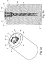
- FIG. 3a there is seen a view of an example of a coil housing 4 at the upper end portion of an assembly 1 which has been inserted and secured into a well 90 of a cylinder head 9.
- the coil housing 4 is arranged with transversally protruding members 41, referred to as "mounting ears", providing a fastening structure via which the fastening means 40 can fasten the seal 4 onto the engine head 9. Fastening may be achieved in many ways, such as via screws or by means of a bayonet coupling.
- the mounting ears 41 are preferably arranged adjacent to gripping surfaces 42 for facilitating removal of the assembly 1 out of a well 90 as will now be described.
- the orifice of the spark plug well 90 of the engine head 9 comprises lifting cams 91 which are arranged to cooperate with the mounting ears 41 of the seal 4 to contribute to removal of the assembly 1 out of a well 90.
- the fastening means 40 if present
- the seal 4 is grasped at the position of the gripping surfaces 42 and the seal 4 rotated such that the mounting ears 41 are urged to slide up and onto the lifting cams 91.
- the entire assembly 1 is lifted in a direction out of the well 90 simultaneous to the rotational movement. This provides for simple and efficient detaching of the assembly 1 from the well 90.
- the flexible material of the extension body may be a material other than rubber, and further the extension body may vary in length depending on the depth of the well 90.
Landscapes
- Engineering & Computer Science (AREA)
- Power Engineering (AREA)
- Chemical & Material Sciences (AREA)
- Combustion & Propulsion (AREA)
- Mechanical Engineering (AREA)
- General Engineering & Computer Science (AREA)
- Ignition Installations For Internal Combustion Engines (AREA)
Description
- The present invention relates to an ignition coil assembly for a spark ignited internal combustion engine comprising an ignition coil where said assembly has a main axis and is configured for insertion in a spark plug well.
- Internal combustion engines comprise spark plugs for initiating combustion driving the engine piston and require a spark to ignite the compressed fuel. Conventionally an ignition coil transforms the battery's low voltage to high voltage needed to create an electric spark in the spark plugs to ignite the fuel. Common for all plugs is that they are arranged to be fitted into a well on the cylinder head piercing the wall of the combustion chamber so that the ignition terminal is brought into contact with the interior of the combustion cylinder. Direct ignition systems, where the ignition coil is mounted directly above each spark plug, are known to be advantageous since they eliminate the need of spark-plug wires and reduces leakage current as well as it makes ignition timing-control easier. Such a system is disclosed in
EP0987435 . These direct ignition systems are usually made up as one integrated assembly comprising both the spark plug as well as the ignition coil, whereby the spark plug is connected to the coil via an interconnecting extension body. The size (length) of the extension body in its turn is dependent on the dimensions of the motor. Spark ignited engines are sometimes designed with a vast distance (often at least 150 mm, sometimes as much as 500 mm) between the engine head and the internal combustion cylinder leading to that large spark plug constructions are needed in order for the ignition terminal to reach the cylinder. In some cases this is due to that the spark ignited engine originates from a converted diesel engine. As a diesel engine lacks spark plugs they are not designed to be serviced and the engine is therefore normally not adapted to promote easy access of any plug. Nevertheless, converting diesel engines into spark ignited engines represent a fast growing area, partly due to an increasing environmental awareness, and the ability of converting a diesel engine leads to the possibility of adapting vehicles already in use (e.g. lorry trucks, city busses etc.) to become e.g. gas-compatible. -
US 2008/0271724 describes an ignition coil apparatus for an internal combustion engine. The apparatus is with a high voltage tower that holds a high voltage terminal in its interior, and a cylindrical plug boot that has electrical insulation and flexibility and is attached at its one end to the high voltage tower, where the plug boot may be installed on a main body of the internal combustion engine by being inserted into a bent plug hole. -
EP 0713005 A2 describes an ignition system for an internal combustion engine wherein insertion of a terminal into a sleeve from above a cap, with an upper portion of the sleeve fitted in a sleeve receiving portion of the cap, causes a ledge on an upper portion of the terminal to advance beyond a ledge of the cap made in rubber into a position lower than the ledge, whereby an upper side of the ledge engages the ledge to prevent the upward movement of the terminal and a lower side of the ledge is locked to an upper end surface of the sleeve to prevent the terminal from slipping of downwards, thereby completely positioning the terminal. -
US 5357233 discloses an ignition apparatus for an internal combustion engine for providing a peaked high voltage current from an ignition coil to a spark plug through a bendable extension device including a first portion extending from the ignition coil, a second portion adapted to be connected to the spark plug and an elastic member connecting the first member to the second member so that the first member moves elastically in relation to the second member. - However, the space available under the hood is often rather limited, even quite narrow, and the lack of space may lead to difficulties when removing and/or introducing the ignition coil assembly from/into the motor. This problem leads to a need of costly design of extensions, e.g. dividing it in several parts.
- It is an object of the present invention to solve, or at least to minimise the above mentioned problems, providing an easy and quick way of removing/introducing the ignition coil assembly from/into an engine cylinder head. This is achieved by an ignition coil assembly according to the appended
claim 1, wherein the assembly comprises an elongated and flexible extension body which comprises an upper end portion and a lower end portion and where said extension body is arranged to be transversally bendable in relation to a main axis so that the upper end portion and the lower end portion of the extension body may assume an angle in relation to each other between 0 - 360°. - In one embodiment the extension body interconnects a spark plug receiving end portion and the ignition coil to each other. Thanks to that the extension body is transversally bendable in relation to the main axis, the spark plug receiving end portion and the ignition coil of the assembly may be configured to assume an angle in relation to each other.
- In a preferred aspect of the invention the extension body is made of a flexible material such as rubber. It is to be understood that the term "flexible" is to be interpreted as capable of being bent without breaking.
- Thanks to the invention there is achieved an assembly which is very easy to handle and which may be configured to fit a large variety of engine types, having various dimensions of the well. Thanks to the extension body the assembly can be adapted in length to a particular well, and due to the flexible property of the extension body, the ignition coil assembly can even be designed to fit deep wells (i.e. requiring a long extension body) without running into practical difficulties when removing/introducing the assembly due to limited space inside the motor compartment. In case of a very lengthy assembly, which normally would pose a problem in a narrow motor compartment, an assembly body according to the invention may simply be bent (e.g. during removal of the assembly) and can thus be adapted to the space available around the well under the hood of the vehicle. Furthermore, it facilitates providing compact engine compartments.
- According to yet another aspect of the invention, said ignition coil is detachably arranged within a first joining section at an upper end portion of the extension body.
- According to yet another aspect of the invention, the spark plug is detachably arranged within a detachable spark plug boot which is removably mounted at a lower end portion of the extension body. Preferably said spark plug boot is made of a flexible and heat resistant material such as silicone rubber, arranged to tightly embrace the spark plug to provide an isolating layer and prevent leakage of high voltage current.
In a preferred embodiment the spark plug boot is arranged to be fitted within an adapter unit (a spark plug boot adapter) which in its turn is attached to a second joining section at the lower end portion of the extension body. The adapter unit is preferably made of a heat resistant and isolating material, such as ceramics or high temperature plastic, whereby there is achieved an efficient insulator between the spark plug and the second lowermost joining section of the assembly. Thanks to this aspect there is achieved the benefit that the soft and heat sensitive parts of the assembly, such as the extension body often being made of a resilient material such as rubber, are protected from the heat of the spark plug and are therefore also kept from destruction. An overheated rubber part could otherwise cause the assembly to break down which may result in difficulties during removal of the assembly or replacement of parts, and/or cause leakage of current. Preferably the spark plug boot is easy to detach from the spark plug adapter and at the same time is dimensioned with regards to its diameter to allow for a spark plug socket to reach the spark plug. -
-
Fig. 1 is a perspective view of an assembly according to one embodiment of the invention, where a bent configuration is illustrated in dashed lines, -
Fig. 2 is a cross sectional view of an assembly according line II inFig. 1 , -
Fig. 3a is a perspective view of an assembly being introduced into a well of a cylinder head, -
Fig. 3b is a cross sectional view of of an assembly being introduced into a well of an cylinder head, -
Fig. 4 is a close-up view according to encircled IV inFig. 2 , -
Fig. 5 is an exploded view of the assembly according to one embodiment of the invention, -
Fig. 6 is another exploded view of the assembly according to one embodiment of the invention. - The invention will hereinafter be described in more detail with reference to the appended drawings. The following description should be considered as preferred form only, and is not decisive in a limiting sense.
- In
Figs. 1 - 6 the ignition coil assembly is generally designated 1. InFig. 1 is shown a perspective view of an embodiment of anassembly 1 according to the invention, andFig. 2 shows a cross section of the assembly according to line II inFig. 1 . The main parts of theassembly 1 comprise a spark plug receivingend portion 10, anignition coil 3 and anelongated extension body 6. Theassembly 1 is configured for insertion in a well 90 of a cylinder head 9 (seeFigs. 3a-b ) which is associated with an internal combustion engine. The spark plug receivingend portion 10 and thecoil 3 are connected to each other by means of theelongated extension body 6 which comprises an inner, generally cylindrical, throughbore 60 through which there is arranged an interconnecting member, for instance in the form of a flexible conductor device such as one or several cable/s 64 or a connecting spring, electrically connecting aspark plug 2 inserted into the spark plug receivingend portion 10, and saidcoil 3. Any commercially available ignition cable can be used. At each end portion of thecable 64 there is preferably arranged connections which is intended for retaining an upper 22 and a lower 24 contact spring. In accordance herewith, in one embodiment there is provided anupper contact spring 22 between thecable 64 and thecoil 3 and alower contact spring 24 between thecable 64 and aspark plug 2 which is positioned at the spark plug receivingend portion 10. Saidcontact springs ignition coil 3 and aspark plug 2. It is to be understood that thecontact springs cable 64 may be replaced by one extended contact spring connecting the spark plug and the coil. It is further understood that the interconnectingmember 64 is a flexible interconnecting conductor of suitable kind, and is not to be limited to cables or springs. - In a preferred embodiment the
assembly 1 is generally cylindrical and has a main axis "A", and saidelongated extension body 6 is arranged to be transversally bendable in relation to the main axis A so that the spark plug receivingend portion 10 and theignition coil 3 may be configured to assume an angle α in relation to each other. Theassembly 1 is shown in a bent configuration by means of dashed lines inFig. 1 in which position theextension body 6 has been bent so that itsupper end portion 62 and itslower end portion 65 have assumed an angle α in relation to each other. Theoretically said angle α may be between 0 - 360°, however it is most likely that it will lie be between 90 - 180°. Bending is achieved by means of saidextension body 6 being made of a flexible, resilient material, which allows for e.g. bending theassembly 1 without breaking it. One suitable material for said extension body could be rubber. - The
ignition coil 3, comprising acore 31 and coils 32, is detachably arranged within a first joiningsection 63 located at theupper end portion 62 of theextension body 6, and is beneficially positioned inside anignition coil casing 30. Theignition coil casing 30 is arranged to be attached onto the first joiningsection 63 by means of acoupling sleeve 34 being threaded, or attached in any other suitable way, onto the exterior of theextension body 6 and thecoil casing 30 respectively, adjoining and retaining the two parts. Thus, in one embodiment saidignition coil casing 30 is provided with outer threading matching the inner threading of thecoupling sleeve 34. - The
assembly 1 is seen to be provided with aspark plug 2 inFigs. 3a - b , where saidspark plug 2 is releasably inserted into the spark plug receivingend portion 10 of theassembly 1. Thespark plug 2 is detachably arranged within anspark plug boot 23 which is removably mounted onto a second joiningsection 66 at alower end portion 65 of theextension body 6. In one embodiment thespark plug boot 23 is located within an adaptor unit 20 (also referred to as "spark plug casing" or "boot adapter") which in its turn is attached to the second joiningsection 66 of theelongated extension body 6. Said boot adapter is preferably made of a material which is heat resistant and preferably an electrical insulator both in high-temperatures and in humid conditions. Examples of suitable material could comprise ceramics or thermoplastics such as polyphenylene sulfide (PPS). Thespark plug boot 23 is detachable from theassembly 1, for instance by means of a snap-in mechanism and may thereby easily be replaced if desired. According to one embodiment thespark plug boot 23 is attached to theboot adapter 20 by means of a snap-in mechanism such that thespark plug boot 23 can be detached from theadaptor 20 regardless of whether the spark plug has gotten stuck to it:
over time, silicone rubber can bond with the silicon ceramic of the spark plug, fusing the boot and the spark plug together so that the spark plug gets stuck. - It is to be understood that the invention also relates to an embodiment where the
ignition coil 3 is positioned directly adjacent to the ignition plug, and saidelongated extension body 6 is connected to the ignition coil so as to form an extension of theassembly 1 to promote easy removing and/or introducing the ignition coil assembly from/into the motor. - Preferably the diameter of the
spark plug boot 23 is smaller than the diameter of the spark plug wrench so that it is still possible to remove/replace the spark plug if it should get stuck. Thus it is possible to remove theplug 2 for instance using a conventional spark plug socket. In one embodiment thespark plug boot 23 is arranged to be removed and discarded together with the spark plug. Preferably thespark plug boot 23 is dimensioned to both being easily detachable from theadaptor unit 20 and to allow for a socket to reach thespark plug 2 properly. Preferably saidspark plug boot 23 is made of a flexible, heat resistant and isolating material, such as silicone rubber, whereby there is achieved an efficient insulator between thespark plug 2 and the second joiningsection 66 of theextension body 6. Thespark plug boot 23 is dimensioned to tightly embrace the spark plug thereby creating an efficient isolating layer and preventing leakage of high voltage current. Thanks to thespark plug boot 23 there is also achieved the advantage that thespark plug 2 is prevented from getting stuck to theadaptor unit 20 because thespark plug boot 23 creates a protecting layer which leads to facilitated detaching of thespark plug boot 23. - The function of the
assembly 1 according to one aspect is now to be described. Adirect ignition assembly 1 according to the invention, shown inFigs. 1 - 6 , is provided, and anspark plug 2 is fitted into thespark plug boot 23 at thelower end portion 65 of theassembly 1. Fitting into place of theplug 2 results in electrical connection with thecoil 3 disposed above theplug 2, via said interconnecting member 64 (e.g. cable and/or spring). Theassembly 1 is introduced into the well 90 of thecylinder head 9 so that the spark plug terminal is brought into contact with the interior of the combustion chamber. This operation is significantly facilitated by means of saidextension body 6 being resilient and flexible since this allows for bending of theassembly 1 during that thelower end portion 65, comprising thespark plug terminal 2, is brought to a proper position for entering the well 90. As an example, if the space available under the hood of a particular vehicle is very narrow and at the same time thewell 90 is lengthy, introducing a conventional, rigid ignition coil assembly would be rather cumbersome. However, anassembly 1 according to the invention will allow for easy and swift introduction even when the well 90 is deep and the assembly body is correspondingly elongated. Bending of theextension body 6 allows for firstly introducing the sparkplug end portion 10, while at the same time theupper end portion 62 at the position of thecoil 3 may be forced to assume an angle α in relation to the main axis A and to the alignment of the spark plug receivingend portion 10. Anassembly 1 according to the invention can hereby be introduced into a well 90 without encountering the problem of the hood blocking the ignition coil assembly from entering the well: if the hood is in the way theextension body 6 is simply bent so that introduction operation may proceed. - Once the
entire assembly body 1 is in place inside the well 90 acoil housing 4 at the uppermost end of theassembly 1 is arranged to secure the assembly onto theengine head 9 so that the well 90 and the chamber is properly sealed. Thecoil housing 4 is attached onto thehead 9 by means of fastening means 40 such as screws or any other conventional/suitable alternative. Thecoil housing 4 comprise aconnector body 5 for electrically connecting the primary terminals of thecoil 3. - In
Fig. 3a there is seen a view of an example of acoil housing 4 at the upper end portion of anassembly 1 which has been inserted and secured into a well 90 of acylinder head 9. As seen herein thecoil housing 4 is arranged with transversally protrudingmembers 41, referred to as "mounting ears", providing a fastening structure via which the fastening means 40 can fasten theseal 4 onto theengine head 9. Fastening may be achieved in many ways, such as via screws or by means of a bayonet coupling. The mountingears 41 are preferably arranged adjacent to grippingsurfaces 42 for facilitating removal of theassembly 1 out of a well 90 as will now be described. According to one aspect of the invention the orifice of the spark plug well 90 of theengine head 9 comprises liftingcams 91 which are arranged to cooperate with the mountingears 41 of theseal 4 to contribute to removal of theassembly 1 out of a well 90. When removing anassembly 1 out of a well 90 the fastening means 40 (if present) are firstly detached whereafter theseal 4 is grasped at the position of thegripping surfaces 42 and theseal 4 rotated such that the mountingears 41 are urged to slide up and onto the liftingcams 91. Hereby theentire assembly 1 is lifted in a direction out of the well 90 simultaneous to the rotational movement. This provides for simple and efficient detaching of theassembly 1 from thewell 90. - The invention is not to be seen as limited by the embodiments described above, but can be varied within the scope of the appended claims. For instance, the flexible material of the extension body may be a material other than rubber, and further the extension body may vary in length depending on the depth of the well 90.
- Many other variations are also possible, as will be readily understood by the person skilled in the art.
Claims (8)
- An ignition coil assembly for an ignition system comprising an ignition coil (3) where said assembly (1) has a main axis (A) and is configured for insertion into and/or removal out of a well (90) associated with an internal combustion engine, and said assembly (1) comprises an elongated extension body (6) made of flexible material, said extension body (6) comprising an upper end portion (62) with a first joining section (63) and a lower end portion (65) wherein the extension body (6) is arranged to be transversally bendable in relation to the main axis (A) so that the upper end portion (62) and the lower end portion (65) may assume an angle (α) in relation to each other , that a spark plug (2) is detachably arranged within a spark plug boot (23) which is removably mounted onto a second joining section (66) at a lower end portion (65) of the extension body (6), characterized in that the spark plug boot (23) has a diameter arranged to allow use of a spark plug wrench to remove the spark plug (2).
- An assembly according to claim 1, wherein the elongated extension body (6) interconnects a spark plug receiving end portion (10) and the ignition coil (3) to each other and which is arranged to be transversally bendable in relation to the main axis (A) so that the spark plug receiving end portion (10) and the ignition coil (3) may be configured to assume an angle in relation to each other.
- An assembly according to claim 1 or 2, wherein said ignition coil (3) is detachably arranged within the first joining section (63) at the upper end portion (62) of the extension body (6).
- An assembly according to anyone of claims 1-3, wherein said extension body (6) is made of a flexible material, preferably rubber.
- An assembly according to anyone of claims 1-4, wherein said extension body (6) has a length that is between 100 - 500 mm, preferably at least 150 mm.
- An assembly according to anyone of claims 1-5, wherein said spark plug boot (23) is detachably arranged within a boot adapter (20) attached at the lower end portion (65) of the extension body (6).
- An assembly according to anyone of claims 1-6, comprising a coil housing (4) arranged with means (40, 41) for connecting an assembly (1) which is positioned inside a well (90) onto a corresponding cylinder head (9), which coil housing (4) further comprises transversally projecting mounting ears (41) arranged to cooperate with vertically protruding lifting structures on the cylinder head (9) to promote easy removal of the assembly (1) out of the well (90).
- Method for mounting an ignition coil assembly (1) according to claim 1 into a well (90) of a cylinder head (9), comprising the steps of- introducing the assembly (1) into said well (90) while adapting the assembly (1) to the space available around the cylinder head by means of transversally bending the extension body (6) in relation to the main axis (A) so that the spark plug portion (65) and the ignition coil (3) are configured to assume an angle in relation to each other, and- fastening the assembly (1) to the cylinder head (9) via a coil housing (4).
Applications Claiming Priority (2)
| Application Number | Priority Date | Filing Date | Title |
|---|---|---|---|
| SE1250485 | 2012-05-14 | ||
| PCT/SE2013/050535 WO2013172771A1 (en) | 2012-05-14 | 2013-05-14 | Spark plug extension |
Publications (3)
| Publication Number | Publication Date |
|---|---|
| EP2850315A1 EP2850315A1 (en) | 2015-03-25 |
| EP2850315A4 EP2850315A4 (en) | 2015-07-08 |
| EP2850315B1 true EP2850315B1 (en) | 2018-08-15 |
Family
ID=49584051
Family Applications (1)
| Application Number | Title | Priority Date | Filing Date |
|---|---|---|---|
| EP13790028.8A Active EP2850315B1 (en) | 2012-05-14 | 2013-05-14 | Spark plug extension |
Country Status (4)
| Country | Link |
|---|---|
| US (1) | US10164410B2 (en) |
| EP (1) | EP2850315B1 (en) |
| CN (1) | CN104364513B (en) |
| WO (1) | WO2013172771A1 (en) |
Families Citing this family (5)
| Publication number | Priority date | Publication date | Assignee | Title |
|---|---|---|---|---|
| JP6772752B2 (en) * | 2016-10-17 | 2020-10-21 | 株式会社デンソー | Ignition coil for internal combustion engine |
| DE102017102575B4 (en) * | 2017-01-31 | 2018-12-20 | Borgwarner Ludwigsburg Gmbh | connector |
| US10511152B2 (en) * | 2017-04-26 | 2019-12-17 | Woodward, Inc. | Method and system for a unique material and geometry in a high temperature spark plug extender |
| SE541409C2 (en) * | 2017-06-19 | 2019-09-24 | Sem Ab | Spark plug extension |
| DE102018108292B4 (en) | 2017-11-17 | 2023-05-11 | Borgwarner Ludwigsburg Gmbh | Connector for connecting an ignition coil to a spark plug and protective tube for a connector |
Family Cites Families (10)
| Publication number | Priority date | Publication date | Assignee | Title |
|---|---|---|---|---|
| US5357233A (en) | 1991-08-23 | 1994-10-18 | Nippondenso Co., Ltd. | Ignition apparatus for internal combustion engine |
| JPH08144918A (en) | 1994-11-17 | 1996-06-04 | Sumitomo Wiring Syst Ltd | Igniter for internal combustion engine |
| JP3556725B2 (en) * | 1995-03-20 | 2004-08-25 | 三菱電機株式会社 | Ignition device for internal combustion engine |
| JP3277750B2 (en) * | 1995-04-26 | 2002-04-22 | 三菱電機株式会社 | Transmission device and ignition device for ignition device of internal combustion engine |
| JP3449183B2 (en) * | 1997-05-22 | 2003-09-22 | 株式会社デンソー | Ignition coil |
| JP2000091057A (en) | 1998-09-14 | 2000-03-31 | Ngk Spark Plug Co Ltd | Direct ignition type plug |
| JP4506352B2 (en) * | 2003-11-26 | 2010-07-21 | 株式会社デンソー | Ignition coil |
| JP4267042B2 (en) * | 2007-05-01 | 2009-05-27 | 三菱電機株式会社 | Ignition coil device for internal combustion engine |
| CN102334252B (en) * | 2009-01-12 | 2013-03-27 | 费德罗-莫格尔点火公司 | Flexible ignitor assembly for air/fuel mixture and method of construction thereof |
| US8063548B2 (en) * | 2009-03-03 | 2011-11-22 | Bobby Glen Bishop | Flexible spark plug |
-
2013
- 2013-05-14 EP EP13790028.8A patent/EP2850315B1/en active Active
- 2013-05-14 WO PCT/SE2013/050535 patent/WO2013172771A1/en not_active Ceased
- 2013-05-14 CN CN201380031130.5A patent/CN104364513B/en active Active
- 2013-05-14 US US14/401,163 patent/US10164410B2/en active Active
Non-Patent Citations (1)
| Title |
|---|
| None * |
Also Published As
| Publication number | Publication date |
|---|---|
| CN104364513A (en) | 2015-02-18 |
| US10164410B2 (en) | 2018-12-25 |
| CN104364513B (en) | 2016-06-22 |
| EP2850315A4 (en) | 2015-07-08 |
| US20150136098A1 (en) | 2015-05-21 |
| WO2013172771A1 (en) | 2013-11-21 |
| EP2850315A1 (en) | 2015-03-25 |
Similar Documents
| Publication | Publication Date | Title |
|---|---|---|
| US10164410B2 (en) | Spark plug extension | |
| EP2377213B1 (en) | Flexible ignitor assembly for air/fuel mixture and method of construction thereof | |
| CN107146984B (en) | The fixed structure of shielded connector | |
| EP2360050A2 (en) | Power supply control device | |
| US20140227649A1 (en) | Method and apparatus for delivering a high voltage to a flame-coupled electrode | |
| CN111180946B (en) | Electrical connector sealing system | |
| KR940002998B1 (en) | Electrical connector for distributor-free ignition system | |
| JP4282206B2 (en) | Plug cap and plug mounting method | |
| AU2022446043B9 (en) | Electric vehicle charging plug with seals | |
| ES2294624T3 (en) | PLUG DEVICE FOR CABLE CONNECTIONS OR APPLIANCES IN AN ELECTRICAL INSTALLATION. | |
| KR20230001833U (en) | Electric vehicle charging plug with seals | |
| CN104981946B (en) | Electrical components with electrical connections | |
| CN106463881B (en) | Replaceable bushing for electrical equipment | |
| CN104114872A (en) | Pump unit with electrical connection plug | |
| US6952948B2 (en) | Spark plug for receiving a pressure sensor and corresponding spark plug connector | |
| JP7504860B2 (en) | Battery charger for electric or hybrid vehicles | |
| US4810198A (en) | Reinforced boot for spark plug cables | |
| US10243309B2 (en) | Engine block heater cord set | |
| US4884977A (en) | Reinforced boot for spark plug cables | |
| CN203377450U (en) | Circular electric connector | |
| US6655368B2 (en) | Ignition coil assembly for engine | |
| KR101875963B1 (en) | Noise removable power oulet and cigar socket apparatus | |
| CN207909606U (en) | Starter motor wiring protecting jacket structure | |
| KR200312338Y1 (en) | Power plug including fuse | |
| KR200431113Y1 (en) | Ring terminal waterproof cap |
Legal Events
| Date | Code | Title | Description |
|---|---|---|---|
| PUAI | Public reference made under article 153(3) epc to a published international application that has entered the european phase |
Free format text: ORIGINAL CODE: 0009012 |
|
| 17P | Request for examination filed |
Effective date: 20141112 |
|
| AK | Designated contracting states |
Kind code of ref document: A1 Designated state(s): AL AT BE BG CH CY CZ DE DK EE ES FI FR GB GR HR HU IE IS IT LI LT LU LV MC MK MT NL NO PL PT RO RS SE SI SK SM TR |
|
| AX | Request for extension of the european patent |
Extension state: BA ME |
|
| RA4 | Supplementary search report drawn up and despatched (corrected) |
Effective date: 20150605 |
|
| RIC1 | Information provided on ipc code assigned before grant |
Ipc: H01F 38/12 20060101ALI20150529BHEP Ipc: F02P 13/00 20060101ALI20150529BHEP Ipc: H01T 13/44 20060101ALI20150529BHEP Ipc: H01T 13/04 20060101ALI20150529BHEP Ipc: F02P 3/02 20060101AFI20150529BHEP |
|
| DAX | Request for extension of the european patent (deleted) | ||
| GRAP | Despatch of communication of intention to grant a patent |
Free format text: ORIGINAL CODE: EPIDOSNIGR1 |
|
| STAA | Information on the status of an ep patent application or granted ep patent |
Free format text: STATUS: GRANT OF PATENT IS INTENDED |
|
| INTG | Intention to grant announced |
Effective date: 20180413 |
|
| GRAS | Grant fee paid |
Free format text: ORIGINAL CODE: EPIDOSNIGR3 |
|
| GRAA | (expected) grant |
Free format text: ORIGINAL CODE: 0009210 |
|
| STAA | Information on the status of an ep patent application or granted ep patent |
Free format text: STATUS: THE PATENT HAS BEEN GRANTED |
|
| AK | Designated contracting states |
Kind code of ref document: B1 Designated state(s): AL AT BE BG CH CY CZ DE DK EE ES FI FR GB GR HR HU IE IS IT LI LT LU LV MC MK MT NL NO PL PT RO RS SE SI SK SM TR |
|
| REG | Reference to a national code |
Ref country code: CH Ref legal event code: EP Ref country code: GB Ref legal event code: FG4D Ref country code: AT Ref legal event code: REF Ref document number: 1030071 Country of ref document: AT Kind code of ref document: T Effective date: 20180815 |
|
| REG | Reference to a national code |
Ref country code: IE Ref legal event code: FG4D |
|
| REG | Reference to a national code |
Ref country code: DE Ref legal event code: R096 Ref document number: 602013042095 Country of ref document: DE |
|
| REG | Reference to a national code |
Ref country code: SE Ref legal event code: TRGR |
|
| REG | Reference to a national code |
Ref country code: NL Ref legal event code: MP Effective date: 20180815 |
|
| REG | Reference to a national code |
Ref country code: LT Ref legal event code: MG4D |
|
| REG | Reference to a national code |
Ref country code: AT Ref legal event code: MK05 Ref document number: 1030071 Country of ref document: AT Kind code of ref document: T Effective date: 20180815 |
|
| PG25 | Lapsed in a contracting state [announced via postgrant information from national office to epo] |
Ref country code: IS Free format text: LAPSE BECAUSE OF FAILURE TO SUBMIT A TRANSLATION OF THE DESCRIPTION OR TO PAY THE FEE WITHIN THE PRESCRIBED TIME-LIMIT Effective date: 20181215 Ref country code: AT Free format text: LAPSE BECAUSE OF FAILURE TO SUBMIT A TRANSLATION OF THE DESCRIPTION OR TO PAY THE FEE WITHIN THE PRESCRIBED TIME-LIMIT Effective date: 20180815 Ref country code: NO Free format text: LAPSE BECAUSE OF FAILURE TO SUBMIT A TRANSLATION OF THE DESCRIPTION OR TO PAY THE FEE WITHIN THE PRESCRIBED TIME-LIMIT Effective date: 20181115 Ref country code: RS Free format text: LAPSE BECAUSE OF FAILURE TO SUBMIT A TRANSLATION OF THE DESCRIPTION OR TO PAY THE FEE WITHIN THE PRESCRIBED TIME-LIMIT Effective date: 20180815 Ref country code: GR Free format text: LAPSE BECAUSE OF FAILURE TO SUBMIT A TRANSLATION OF THE DESCRIPTION OR TO PAY THE FEE WITHIN THE PRESCRIBED TIME-LIMIT Effective date: 20181116 Ref country code: FI Free format text: LAPSE BECAUSE OF FAILURE TO SUBMIT A TRANSLATION OF THE DESCRIPTION OR TO PAY THE FEE WITHIN THE PRESCRIBED TIME-LIMIT Effective date: 20180815 Ref country code: NL Free format text: LAPSE BECAUSE OF FAILURE TO SUBMIT A TRANSLATION OF THE DESCRIPTION OR TO PAY THE FEE WITHIN THE PRESCRIBED TIME-LIMIT Effective date: 20180815 Ref country code: BG Free format text: LAPSE BECAUSE OF FAILURE TO SUBMIT A TRANSLATION OF THE DESCRIPTION OR TO PAY THE FEE WITHIN THE PRESCRIBED TIME-LIMIT Effective date: 20181115 Ref country code: LT Free format text: LAPSE BECAUSE OF FAILURE TO SUBMIT A TRANSLATION OF THE DESCRIPTION OR TO PAY THE FEE WITHIN THE PRESCRIBED TIME-LIMIT Effective date: 20180815 |
|
| PG25 | Lapsed in a contracting state [announced via postgrant information from national office to epo] |
Ref country code: HR Free format text: LAPSE BECAUSE OF FAILURE TO SUBMIT A TRANSLATION OF THE DESCRIPTION OR TO PAY THE FEE WITHIN THE PRESCRIBED TIME-LIMIT Effective date: 20180815 Ref country code: LV Free format text: LAPSE BECAUSE OF FAILURE TO SUBMIT A TRANSLATION OF THE DESCRIPTION OR TO PAY THE FEE WITHIN THE PRESCRIBED TIME-LIMIT Effective date: 20180815 Ref country code: AL Free format text: LAPSE BECAUSE OF FAILURE TO SUBMIT A TRANSLATION OF THE DESCRIPTION OR TO PAY THE FEE WITHIN THE PRESCRIBED TIME-LIMIT Effective date: 20180815 |
|
| PG25 | Lapsed in a contracting state [announced via postgrant information from national office to epo] |
Ref country code: CZ Free format text: LAPSE BECAUSE OF FAILURE TO SUBMIT A TRANSLATION OF THE DESCRIPTION OR TO PAY THE FEE WITHIN THE PRESCRIBED TIME-LIMIT Effective date: 20180815 Ref country code: RO Free format text: LAPSE BECAUSE OF FAILURE TO SUBMIT A TRANSLATION OF THE DESCRIPTION OR TO PAY THE FEE WITHIN THE PRESCRIBED TIME-LIMIT Effective date: 20180815 Ref country code: ES Free format text: LAPSE BECAUSE OF FAILURE TO SUBMIT A TRANSLATION OF THE DESCRIPTION OR TO PAY THE FEE WITHIN THE PRESCRIBED TIME-LIMIT Effective date: 20180815 Ref country code: PL Free format text: LAPSE BECAUSE OF FAILURE TO SUBMIT A TRANSLATION OF THE DESCRIPTION OR TO PAY THE FEE WITHIN THE PRESCRIBED TIME-LIMIT Effective date: 20180815 Ref country code: EE Free format text: LAPSE BECAUSE OF FAILURE TO SUBMIT A TRANSLATION OF THE DESCRIPTION OR TO PAY THE FEE WITHIN THE PRESCRIBED TIME-LIMIT Effective date: 20180815 |
|
| REG | Reference to a national code |
Ref country code: DE Ref legal event code: R097 Ref document number: 602013042095 Country of ref document: DE |
|
| PG25 | Lapsed in a contracting state [announced via postgrant information from national office to epo] |
Ref country code: SM Free format text: LAPSE BECAUSE OF FAILURE TO SUBMIT A TRANSLATION OF THE DESCRIPTION OR TO PAY THE FEE WITHIN THE PRESCRIBED TIME-LIMIT Effective date: 20180815 Ref country code: DK Free format text: LAPSE BECAUSE OF FAILURE TO SUBMIT A TRANSLATION OF THE DESCRIPTION OR TO PAY THE FEE WITHIN THE PRESCRIBED TIME-LIMIT Effective date: 20180815 Ref country code: SK Free format text: LAPSE BECAUSE OF FAILURE TO SUBMIT A TRANSLATION OF THE DESCRIPTION OR TO PAY THE FEE WITHIN THE PRESCRIBED TIME-LIMIT Effective date: 20180815 |
|
| PLBE | No opposition filed within time limit |
Free format text: ORIGINAL CODE: 0009261 |
|
| STAA | Information on the status of an ep patent application or granted ep patent |
Free format text: STATUS: NO OPPOSITION FILED WITHIN TIME LIMIT |
|
| 26N | No opposition filed |
Effective date: 20190516 |
|
| PG25 | Lapsed in a contracting state [announced via postgrant information from national office to epo] |
Ref country code: SI Free format text: LAPSE BECAUSE OF FAILURE TO SUBMIT A TRANSLATION OF THE DESCRIPTION OR TO PAY THE FEE WITHIN THE PRESCRIBED TIME-LIMIT Effective date: 20180815 |
|
| REG | Reference to a national code |
Ref country code: CH Ref legal event code: PL |
|
| GBPC | Gb: european patent ceased through non-payment of renewal fee |
Effective date: 20190514 |
|
| PG25 | Lapsed in a contracting state [announced via postgrant information from national office to epo] |
Ref country code: LI Free format text: LAPSE BECAUSE OF NON-PAYMENT OF DUE FEES Effective date: 20190531 Ref country code: MC Free format text: LAPSE BECAUSE OF FAILURE TO SUBMIT A TRANSLATION OF THE DESCRIPTION OR TO PAY THE FEE WITHIN THE PRESCRIBED TIME-LIMIT Effective date: 20180815 Ref country code: CH Free format text: LAPSE BECAUSE OF NON-PAYMENT OF DUE FEES Effective date: 20190531 |
|
| REG | Reference to a national code |
Ref country code: BE Ref legal event code: MM Effective date: 20190531 |
|
| PG25 | Lapsed in a contracting state [announced via postgrant information from national office to epo] |
Ref country code: LU Free format text: LAPSE BECAUSE OF NON-PAYMENT OF DUE FEES Effective date: 20190514 |
|
| PG25 | Lapsed in a contracting state [announced via postgrant information from national office to epo] |
Ref country code: TR Free format text: LAPSE BECAUSE OF FAILURE TO SUBMIT A TRANSLATION OF THE DESCRIPTION OR TO PAY THE FEE WITHIN THE PRESCRIBED TIME-LIMIT Effective date: 20180815 |
|
| PG25 | Lapsed in a contracting state [announced via postgrant information from national office to epo] |
Ref country code: GB Free format text: LAPSE BECAUSE OF NON-PAYMENT OF DUE FEES Effective date: 20190514 Ref country code: IE Free format text: LAPSE BECAUSE OF NON-PAYMENT OF DUE FEES Effective date: 20190514 |
|
| PG25 | Lapsed in a contracting state [announced via postgrant information from national office to epo] |
Ref country code: BE Free format text: LAPSE BECAUSE OF NON-PAYMENT OF DUE FEES Effective date: 20190531 |
|
| PG25 | Lapsed in a contracting state [announced via postgrant information from national office to epo] |
Ref country code: PT Free format text: LAPSE BECAUSE OF FAILURE TO SUBMIT A TRANSLATION OF THE DESCRIPTION OR TO PAY THE FEE WITHIN THE PRESCRIBED TIME-LIMIT Effective date: 20181215 |
|
| PG25 | Lapsed in a contracting state [announced via postgrant information from national office to epo] |
Ref country code: CY Free format text: LAPSE BECAUSE OF FAILURE TO SUBMIT A TRANSLATION OF THE DESCRIPTION OR TO PAY THE FEE WITHIN THE PRESCRIBED TIME-LIMIT Effective date: 20180815 |
|
| PG25 | Lapsed in a contracting state [announced via postgrant information from national office to epo] |
Ref country code: MT Free format text: LAPSE BECAUSE OF FAILURE TO SUBMIT A TRANSLATION OF THE DESCRIPTION OR TO PAY THE FEE WITHIN THE PRESCRIBED TIME-LIMIT Effective date: 20180815 Ref country code: HU Free format text: LAPSE BECAUSE OF FAILURE TO SUBMIT A TRANSLATION OF THE DESCRIPTION OR TO PAY THE FEE WITHIN THE PRESCRIBED TIME-LIMIT; INVALID AB INITIO Effective date: 20130514 |
|
| PGFP | Annual fee paid to national office [announced via postgrant information from national office to epo] |
Ref country code: FR Payment date: 20210519 Year of fee payment: 9 |
|
| PG25 | Lapsed in a contracting state [announced via postgrant information from national office to epo] |
Ref country code: MK Free format text: LAPSE BECAUSE OF FAILURE TO SUBMIT A TRANSLATION OF THE DESCRIPTION OR TO PAY THE FEE WITHIN THE PRESCRIBED TIME-LIMIT Effective date: 20180815 |
|
| PG25 | Lapsed in a contracting state [announced via postgrant information from national office to epo] |
Ref country code: FR Free format text: LAPSE BECAUSE OF NON-PAYMENT OF DUE FEES Effective date: 20220531 |
|
| PGFP | Annual fee paid to national office [announced via postgrant information from national office to epo] |
Ref country code: DE Payment date: 20250512 Year of fee payment: 13 |
|
| PGFP | Annual fee paid to national office [announced via postgrant information from national office to epo] |
Ref country code: IT Payment date: 20250512 Year of fee payment: 13 |
|
| PGFP | Annual fee paid to national office [announced via postgrant information from national office to epo] |
Ref country code: SE Payment date: 20250515 Year of fee payment: 13 |