EP2849687B1 - Treppenaufstiegs- und abstiegssteuerung für angetriebene untere gliedmassenvorrichtungen - Google Patents
Treppenaufstiegs- und abstiegssteuerung für angetriebene untere gliedmassenvorrichtungen Download PDFInfo
- Publication number
- EP2849687B1 EP2849687B1 EP13713653.7A EP13713653A EP2849687B1 EP 2849687 B1 EP2849687 B1 EP 2849687B1 EP 13713653 A EP13713653 A EP 13713653A EP 2849687 B1 EP2849687 B1 EP 2849687B1
- Authority
- EP
- European Patent Office
- Prior art keywords
- state
- knee
- ankle
- powered
- lower limb
- Prior art date
- Legal status (The legal status is an assumption and is not a legal conclusion. Google has not performed a legal analysis and makes no representation as to the accuracy of the status listed.)
- Active
Links
Images


Classifications
-
- A—HUMAN NECESSITIES
- A61—MEDICAL OR VETERINARY SCIENCE; HYGIENE
- A61F—FILTERS IMPLANTABLE INTO BLOOD VESSELS; PROSTHESES; DEVICES PROVIDING PATENCY TO, OR PREVENTING COLLAPSING OF, TUBULAR STRUCTURES OF THE BODY, e.g. STENTS; ORTHOPAEDIC, NURSING OR CONTRACEPTIVE DEVICES; FOMENTATION; TREATMENT OR PROTECTION OF EYES OR EARS; BANDAGES, DRESSINGS OR ABSORBENT PADS; FIRST-AID KITS
- A61F2/00—Filters implantable into blood vessels; Prostheses, i.e. artificial substitutes or replacements for parts of the body; Appliances for connecting them with the body; Devices providing patency to, or preventing collapsing of, tubular structures of the body, e.g. stents
- A61F2/50—Prostheses not implantable in the body
- A61F2/68—Operating or control means
- A61F2/70—Operating or control means electrical
-
- A—HUMAN NECESSITIES
- A61—MEDICAL OR VETERINARY SCIENCE; HYGIENE
- A61F—FILTERS IMPLANTABLE INTO BLOOD VESSELS; PROSTHESES; DEVICES PROVIDING PATENCY TO, OR PREVENTING COLLAPSING OF, TUBULAR STRUCTURES OF THE BODY, e.g. STENTS; ORTHOPAEDIC, NURSING OR CONTRACEPTIVE DEVICES; FOMENTATION; TREATMENT OR PROTECTION OF EYES OR EARS; BANDAGES, DRESSINGS OR ABSORBENT PADS; FIRST-AID KITS
- A61F2/00—Filters implantable into blood vessels; Prostheses, i.e. artificial substitutes or replacements for parts of the body; Appliances for connecting them with the body; Devices providing patency to, or preventing collapsing of, tubular structures of the body, e.g. stents
- A61F2/50—Prostheses not implantable in the body
- A61F2/60—Artificial legs or feet or parts thereof
- A61F2/64—Knee joints
-
- A—HUMAN NECESSITIES
- A61—MEDICAL OR VETERINARY SCIENCE; HYGIENE
- A61F—FILTERS IMPLANTABLE INTO BLOOD VESSELS; PROSTHESES; DEVICES PROVIDING PATENCY TO, OR PREVENTING COLLAPSING OF, TUBULAR STRUCTURES OF THE BODY, e.g. STENTS; ORTHOPAEDIC, NURSING OR CONTRACEPTIVE DEVICES; FOMENTATION; TREATMENT OR PROTECTION OF EYES OR EARS; BANDAGES, DRESSINGS OR ABSORBENT PADS; FIRST-AID KITS
- A61F2/00—Filters implantable into blood vessels; Prostheses, i.e. artificial substitutes or replacements for parts of the body; Appliances for connecting them with the body; Devices providing patency to, or preventing collapsing of, tubular structures of the body, e.g. stents
- A61F2/50—Prostheses not implantable in the body
- A61F2/60—Artificial legs or feet or parts thereof
- A61F2/66—Feet; Ankle joints
- A61F2/6607—Ankle joints
-
- A—HUMAN NECESSITIES
- A61—MEDICAL OR VETERINARY SCIENCE; HYGIENE
- A61F—FILTERS IMPLANTABLE INTO BLOOD VESSELS; PROSTHESES; DEVICES PROVIDING PATENCY TO, OR PREVENTING COLLAPSING OF, TUBULAR STRUCTURES OF THE BODY, e.g. STENTS; ORTHOPAEDIC, NURSING OR CONTRACEPTIVE DEVICES; FOMENTATION; TREATMENT OR PROTECTION OF EYES OR EARS; BANDAGES, DRESSINGS OR ABSORBENT PADS; FIRST-AID KITS
- A61F2/00—Filters implantable into blood vessels; Prostheses, i.e. artificial substitutes or replacements for parts of the body; Appliances for connecting them with the body; Devices providing patency to, or preventing collapsing of, tubular structures of the body, e.g. stents
- A61F2/50—Prostheses not implantable in the body
- A61F2/60—Artificial legs or feet or parts thereof
- A61F2002/607—Lower legs
-
- A—HUMAN NECESSITIES
- A61—MEDICAL OR VETERINARY SCIENCE; HYGIENE
- A61F—FILTERS IMPLANTABLE INTO BLOOD VESSELS; PROSTHESES; DEVICES PROVIDING PATENCY TO, OR PREVENTING COLLAPSING OF, TUBULAR STRUCTURES OF THE BODY, e.g. STENTS; ORTHOPAEDIC, NURSING OR CONTRACEPTIVE DEVICES; FOMENTATION; TREATMENT OR PROTECTION OF EYES OR EARS; BANDAGES, DRESSINGS OR ABSORBENT PADS; FIRST-AID KITS
- A61F2/00—Filters implantable into blood vessels; Prostheses, i.e. artificial substitutes or replacements for parts of the body; Appliances for connecting them with the body; Devices providing patency to, or preventing collapsing of, tubular structures of the body, e.g. stents
- A61F2/50—Prostheses not implantable in the body
- A61F2/68—Operating or control means
- A61F2/70—Operating or control means electrical
- A61F2002/701—Operating or control means electrical operated by electrically controlled means, e.g. solenoids or torque motors
-
- A—HUMAN NECESSITIES
- A61—MEDICAL OR VETERINARY SCIENCE; HYGIENE
- A61F—FILTERS IMPLANTABLE INTO BLOOD VESSELS; PROSTHESES; DEVICES PROVIDING PATENCY TO, OR PREVENTING COLLAPSING OF, TUBULAR STRUCTURES OF THE BODY, e.g. STENTS; ORTHOPAEDIC, NURSING OR CONTRACEPTIVE DEVICES; FOMENTATION; TREATMENT OR PROTECTION OF EYES OR EARS; BANDAGES, DRESSINGS OR ABSORBENT PADS; FIRST-AID KITS
- A61F2/00—Filters implantable into blood vessels; Prostheses, i.e. artificial substitutes or replacements for parts of the body; Appliances for connecting them with the body; Devices providing patency to, or preventing collapsing of, tubular structures of the body, e.g. stents
- A61F2/50—Prostheses not implantable in the body
- A61F2/68—Operating or control means
- A61F2/70—Operating or control means electrical
- A61F2002/704—Operating or control means electrical computer-controlled, e.g. robotic control
-
- A—HUMAN NECESSITIES
- A61—MEDICAL OR VETERINARY SCIENCE; HYGIENE
- A61F—FILTERS IMPLANTABLE INTO BLOOD VESSELS; PROSTHESES; DEVICES PROVIDING PATENCY TO, OR PREVENTING COLLAPSING OF, TUBULAR STRUCTURES OF THE BODY, e.g. STENTS; ORTHOPAEDIC, NURSING OR CONTRACEPTIVE DEVICES; FOMENTATION; TREATMENT OR PROTECTION OF EYES OR EARS; BANDAGES, DRESSINGS OR ABSORBENT PADS; FIRST-AID KITS
- A61F2/00—Filters implantable into blood vessels; Prostheses, i.e. artificial substitutes or replacements for parts of the body; Appliances for connecting them with the body; Devices providing patency to, or preventing collapsing of, tubular structures of the body, e.g. stents
- A61F2/50—Prostheses not implantable in the body
- A61F2/76—Means for assembling, fitting or testing prostheses, e.g. for measuring or balancing, e.g. alignment means
- A61F2002/7615—Measuring means
- A61F2002/7625—Measuring means for measuring angular position
-
- A—HUMAN NECESSITIES
- A61—MEDICAL OR VETERINARY SCIENCE; HYGIENE
- A61F—FILTERS IMPLANTABLE INTO BLOOD VESSELS; PROSTHESES; DEVICES PROVIDING PATENCY TO, OR PREVENTING COLLAPSING OF, TUBULAR STRUCTURES OF THE BODY, e.g. STENTS; ORTHOPAEDIC, NURSING OR CONTRACEPTIVE DEVICES; FOMENTATION; TREATMENT OR PROTECTION OF EYES OR EARS; BANDAGES, DRESSINGS OR ABSORBENT PADS; FIRST-AID KITS
- A61F2/00—Filters implantable into blood vessels; Prostheses, i.e. artificial substitutes or replacements for parts of the body; Appliances for connecting them with the body; Devices providing patency to, or preventing collapsing of, tubular structures of the body, e.g. stents
- A61F2/50—Prostheses not implantable in the body
- A61F2/76—Means for assembling, fitting or testing prostheses, e.g. for measuring or balancing, e.g. alignment means
- A61F2002/7615—Measuring means
- A61F2002/7635—Measuring means for measuring force, pressure or mechanical tension
Definitions
- the present invention relates to control of powered lower limb devices, and more specifically to apparatus and methods for stair ascent and descent control for powered lower limb devices.
- Stair descent is characterized by forefoot strike rather than heel strike, which enables the ankle joint to dissipate substantial power during the loading phase of gait.
- a typical passive (compliant) ankle/foot prosthesis is unable to provide the appropriate ankle posture during terminal swing phase to set up forefoot strike, and is similarly unable to absorb energy (without later releasing that energy) during the loading phase of stair descent.
- Document US 2011/224803 which is regarded as the closest prior art, discloses a method of operating a lower limb device comprising a powered knee joint and a powered ankle joint according to the preamble of claims 1 and 7.
- an activity mode recognizer detects the activity mode of the prosthesis, including stair ascent or stair descent.
- WO 2010/088635 and US 2009/222105 disclose a lower limb devices comprising both a powered knee joint and a powered ankle joint.
- the device of WO 2010/088635 has no specific finite state model for stair ascent/descent activities, but self-adapts to terrain condition; the device of US 2009/222105 may be controlled by specific finite state models depending on the detected activity mode, but US 2009/222105 does not provide any details about specific finite state models for stair ascent/descent activities.
- the lower limb devices disclosed in either one of US 2010/023133 , US 5 571 205 or US 2010/185124 do not comprise both a powered knee joint and a powered ankle joint.
- Embodiments of the invention concern apparatus and methods for stair ascent and descent control for powered lower limb devices comprising a powered knee joint and a powered ankle joint.
- a method as defined in independent claim 1, of operating such a lower limb device, the method including configuring the lower limb device to a state of a finite state model for a current activity mode including a stair ascent mode.
- a method, as defined in independent claim 7, of operating the lower limb device including configuring the lower limb device to a state in a finite state model for a current activity mode including a stair descent mode.
- a computer-readable medium as defined in independent claim 14 having stored thereon a plurality of instructions for causing a computing device to perform any of the methods described above.
- a lower limb device including a powered knee joint and a powered ankle joint, as defined in independent claim 15.
- the various embodiments provide a new stair ascent and descent control system (“stair controller”) for a powered knee and ankle prostheses.
- the stair controller can be configured to supplement an existing control system for a lower limb prosthesis.
- ascent and descent can be controlled by providing activity-level controllers implemented in the form of a finite state machine (FSM). Each state within the FSM generates torque commands for the knee and ankle joints that ensure passivity within the state. Further, the states and transitions between the states are selected so as to provide a gait during ascent and descent that approximates the gait in an individual with healthy lower limbs.
- FSM finite state machine
- FIGs. 1A-30 Prior to discussing the stair ascent and descent, the disclosure first turns to FIGs. 1A-30 to describe various configurations for powered leg and ankle prostheses, including a controller, which can be modified to include a stair controller in accordance with the various embodiments of the invention.
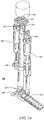
- FIGs. 1A through FIG. 6B A first design for a prosthesis for use in the various embodiments of the invention is shown in FIGs. 1A through FIG. 6B .
- the prosthesis 100 comprises a prosthetic lower leg 101.
- Lower leg 101 can be coupled to a powered knee joint comprising a knee motor unit 105 coupled to a knee joint 110, and a powered ankle joint comprising an ankle motor 115 coupled to an ankle joint 120.
- a sagittal plane moment sensor 125 can be located between the prosthesis and the user to measure the moment, and in one embodiment is located immediately below the socket interface. In the embodiment shown, sensor 125 measures the sagittal plane moment, while separate sensors described below measure the ball of foot force and heel force with respect to the ground or other object the foot is pressed against.
- a load sensor 135 can be positioned at the ball of the foot, and a load sensor 140 can be positioned at the heel of the foot.
- sensor 125 can measure the sagittal plane moment, the frontal plane moment and the axial force, such as provided by the three-axis socket load cell. This alternate embodiment can eliminate the need for sensor 135 and sensor 140.
- Load sensors 141 and 142 are in series with each motor unit 105 and 115, respectively for motor unit force control.
- Position sensors 151 and 152 are provided at each joint 110 and 120 as shown in FIGs. 4 and 5 respectively.
- Position sensors 151 measure joint angle ( ⁇ as used below) and can be embodied as potentiometers.
- the computer/process controller, and power source e.g. a battery such as a Li ion battery, and electrical connections in the case of an electrical power source are not shown to avoid obscuring aspects of the invention.
- Non-electrical power sources may also be used, such as pneumatic power, or non-battery electrical sources, such as hydrogen-based fuel cells.
- Prosthesis 100 is shown in an exploded view in FIG. 1B .
- Joints 110 and 120 are more clearly shown as compared to FIG. 1A .
- FIG. 2 is an exploded view of knee motor unit 105, according to an embodiment of the invention.
- Load sensor 141 is shown as a load cell (e.g. strain gauge). Load sensor 141 measures force and moments.
- the motor unit 105 comprises a motor-driven ball screw assembly which drives the knee joint through a slider-crank linkage comprising screw 145. Other motor drive assemblies may also generally be used.
- FIG. 3 is an exploded view of ankle motor unit 115, according to an embodiment of the invention.
- Load sensor 142 is generally analogous to load sensor 141.
- the motor unit 115 comprises a motor-driven ball screw assembly which drives the ankle joint through a slider-crank linkage comprising screw 145.
- the ankle motor 115 includes a spring 147 positioned to provide power in parallel (thus being additive) with power provided by the motor unit 115. Spring 147 biases the motor unit's force output toward ankle plantarflexion, and supplements the power output provided by motor unit 115 during ankle push off.
- FIG. 4 is an exploded view of knee joint 110, according to an embodiment of the invention.
- knee joint 110 includes position sensor 151 that can be embodied as a potentiometer for angle measurements of the knee joint 110.
- FIG. 5 is an exploded view of ankle joint 120, according to an embodiment of the invention.
- ankle joint 120 includes position sensor 152 that can be embodied as a potentiometer for angle measurements of the ankle joint 120.
- FIG. 6A is a view of a foot 170 having ball of foot sensors 135, according to an embodiment of the invention. Sensors 135 are provided to measure the ground reaction forces near the ball of the foot, such as when the foot strikes the ground.
- FIG. 6B is a view of a foot 170 having ball of foot sensors 135 and heel sensors 140, according to an embodiment of the invention. Sensors 140 are provided to measure the ground reaction forces on the heel of the foot when the foot 170 strikes the ground. Sensors 135 and 140 can be embodied as strain based sensors.
- embodiments of the invention infer commands from the user via the (ipsilateral) forces and moments of interaction between the user and prosthesis.
- the user interacts with the prosthesis by imparting forces and moments from the residual limb to the prosthesis, all of which can be measured via suitable sensor(s), such as sensors 125, 140 and 141 described above which measures moments/forces.
- suitable sensor(s) such as sensors 125, 140 and 141 described above which measures moments/forces.
- the torque required at each joint during a single stride can be piecewise represented by a series of passive impedance functions.
- k 1 characterizes the linear stiffness
- b is the linear damping coefficient
- ⁇ is the measured joint angle which can characterize the state of the prosthesis
- ⁇ e is the equilibrium angle
- ⁇ is the angular velocity of the joint
- ⁇ is the joint torque.
- power can be delivered from the power source (e.g. battery) to the prosthesis in the proper magnitude to provide the desired movement. Since the switching can be triggered by direct input from the user related to the current internal phase, the user maintains direct influence over the power applied to the prosthesis. If the user does not trigger the next internal phase (i.e. remains stationary) no net energy is delivered. That is, the prosthesis will generally cease to receive power from the power source for moving the joint, and will instead, due to the damped response, soon come to rest at the local equilibrium identified with the present internal phase.
- the power source e.g. battery
- the decomposition of joint behavior into passive segments requires the division of the gait cycle into a plurality of internal phases or "finite states" characterized by an impedance function and a set of constants for the impedance function, as dictated by their functions and the character of the piecewise segments of the impedance functions described above.
- the switching rules between internal phases should generally be well defined and measurable, and the number of phases should be sufficient to provide a substantially accurate representation of normal joint function.
- the swing and stance phase of gait can constitute a minimal set of internal phases.
- Equation 1 Based on least-squares regression fitting of Equation 1 to empirical gait data, the present Inventors determined that such fits were improved significantly by further dividing the two modes of swing and stance each into two additional internal phases to realize four phases, as shown in FIG. 8 .
- a fifth internal phase can also be added, as illustrated in FIG. 16 .
- the angle ( ⁇ ) of the prosthetic knee (above) and ankle joint (below) can be provided during each internal phase as a function of the % of the stride. Angle values shown can be used as threshold values to trigger phase changes as described below relative to FIG. 9 .
- the number of phases can be other than two or four.
- FIG. 9 shows exemplary switching rules between internal phases for walking.
- FIG. 16 shows another set exemplary switching rules, for walking, standing, and sitting activity modes.
- the prosthesis will cease to receive power and will come to rest at the local equilibrium identified with the present phase.
- switching can be based on the ankle angle > a threshold value (mode 1 to mode 2), or ankle torque ⁇ threshold) (mode 2 to mode 3), the angle or torque measurements provided by on board sensors as described above.
- Phase 1 shown in FIG. 8 begins with a heel strike by the user (which can be sensed by the heel force sensor), upon which the knee immediately begins to flex so as to provide impact absorption and begin loading, while the ankle simultaneously plantarflexes to reach a flat foot state.
- Both knee and ankle joints have relatively high stiffness (and can be accounted for by k1 in equation 1) during this phase to prevent buckling and allow for appropriate stance knee flexion, because phase 1 comprises most of the weight bearing functionality.
- Phase 2 is the push-off phase and begins as the ankle dorsiflexes beyond a given angle (i.e. user's center of mass lies forward of stance foot). The knee stiffness decreases in this mode to allow knee flexion while the ankle provides a plantarflexive torque for push-off.
- Phase 3 begins as the foot leaves the ground as detected by the ankle torque load cell and lasts until the knee reaches maximum flexion.
- Mode 4 is active during the extension of the knee joint (i.e. as the lower leg swings forward), which begins as the knee velocity becomes negative and ends at heel strike (e.g. as determined by the heel force sensor).
- the ankle torque can be small and can be represented in the controller as a (relatively) weak spring regulated to a neutral position.
- the knee can be primarily treated as a damper in both swing phases.
- Impedance modeling of joint torques was preliminarily validated by utilizing the gait data from a healthy 75 kg subject, as derived from body-mass normalized data. Incorporating the four internal phases described above, along with the motion and torque data for each joint, a constrained least-squares optimization was conducted to generate a set of parameters k 1 , b and ⁇ e for each phase for each joint for use in Equation 1. The resulting parameter set can be fit to joint torques and is shown graphically in FIG. 10.
- FIG. 10 shows piecewise fitting of knee and ankle torques during normal speed level walk scaled for a 75 kg adult to a non-linear spring-damper impedance model.
- the numbers shown in each phase represent the mean ratio of the stiffness forces to damping forces predicted by the fit.
- the vertical lines represent the segmentation of a gait stride into four distinct phases.
- the fit shown in FIG. 10 clearly indicates that normal joint function can be represented by the use of piecewise passive functions.
- Controllers generally comprise an underlying gait controller (intra-modal controller).
- An optional supervisory gait controller also called intent recognizer
- Both controllers generally utilize measured information.
- This information generally comprises user and ground interaction forces (F) and moments/torques ( ⁇ ), joint angles and angular velocities from on-board sensors, and can be used to extract real-time input from the user.
- the gait control component utilizes the sensed instantaneous nature of the user input (i.e., moments and forces) to control the behavior of the leg within a given activity mode, such as standing, walking, or stair climbing.
- the first approach is shown in FIG. 11 and represents a general form of active-passive decomposition-based intra-mode control.
- the second embodiment shown in FIG. 12 includes the control structure shown in FIG. 11 but adds a supervisory intent recognizing controller to modulate the intra-modal control based on inputs from an intent recognition module.
- F s is the force the user of the prosthesis is applying, such as a heel force in the case of a heel strike
- ⁇ represents joint torque
- ⁇ represent joint angles
- ⁇ a represents the active component of joint torque which is roughly proportional to the input force
- ⁇ p represents the passive component of torque.
- the active joint torque ⁇ a is thus the total joint torque ⁇ minus the passive joint torque, ⁇ p.
- Derivatives are shown using the dot convention, with one dot being the first derivative (e.g., ⁇ being angular velocity) and two dots representing the second derivative.
- the behavior of the prosthesis can be decomposed into a passive component and an active control component.
- the active control component is an algebraic function of the user's real-time input F s (i.e., sensed socket-prosthesis interface forces and moments and sensed ground reaction forces).
- the controller output is shown as the active torque ( ⁇ a ) minus the passive torque ⁇ p .
- the controller output ⁇ a - ⁇ p applied to the prosthetic leg based on dynamics of the leg responds via ⁇ and ⁇ .
- the system response, ⁇ and ⁇ is fed back to the controller.
- Power applied to the prosthesis can be thus commanded directly by the user through measured interface forces and moments initiated by user movements.
- the prosthesis under it's own control can be generally stable and passive.
- the input can be real-time, based only on the affected leg, and thus the approach can be equally applicable to bilateral and unilateral amputees and can reflect the instantaneous intent of the user.
- the prosthesis will exhibit a natural impedance to the user that should feel more like a natural limb. These combined features should result in an active prosthesis that will feel inasmuch as possible like a natural extension of the user.
- the structure and properties of both the gait controller and intent recognizer are described below.
- joint behavior can be functionally decomposed over a period by decomposing the joint torque into a passive component and an active component.
- the passive component can comprise a function of angle (i.e., single-valued and odd), and a function of angular velocity passive (i.e., single-valued and odd), such as equation 1 described above.
- the active component can be a function of the user input (i.e., socket interface forces). Given a set of data that characterizes a nominal period of joint behavior, the passive component can be first extracted from the whole, since the passive behavior is a subset of the whole (i.e., the passive component consists of single-valued and odd functions, while the active has no restrictions in form).
- the passive component can be extracted by utilizing a least squares minimization to fit a generalized singled-valued odd function of angle and angular velocity to the torque.
- the residual torque i.e., the portion that is not extracted as a passive component
- the residual torque can be constructed as an algebraic function of the sensed socket interface and ground reaction forces (i.e., the direct-acting user input) by incorporating a similar candidate function, but not restricted to be of passive form.
- ground reaction forces i.e., the direct-acting user input
- a supervisory intent recognizer can be added that utilizes the same sensed user inputs (i.e., moments and forces) as the intra-modal/gait controller, but extracts the user's intent based on the characteristic shape of the user input(s) and system response (e.g. F, ⁇ , ⁇ -dot). Based on the extracted intent, the supervisory intent recognizer modulates the behavior of the underlying gait controller to smoothly transition behavior within a gait (e.g., speed and slope accommodation) and between gaits (e.g., level walk to stair ascent), thus offering a unified control structure within and across all gaits.
- a gait e.g., speed and slope accommodation
- gaits e.g., level walk to stair ascent
- Gait intent recognition can be a real-time pattern recognition or signal classification problem.
- the signal in this case is generally the combination of socket interface forces Fs and the dynamic state of the prosthesis, which in one embodiment can be a vector of the knee and ankle angles ⁇ for a powered leg prosthesis according to an embodiment of the invention.
- a variety of methods exist for pattern recognition and signal classification including nearest neighbor algorithms, neural networks, fuzzy classifiers, linear discriminant analysis, and genetic algorithms.
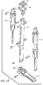
- FIG. 13A is a side view of powered knee and ankle prosthesis 1300, according to another embodiment of the invention.
- FIG. 13B is a front view of powered knee and ankle prosthesis of FIG. 13A .
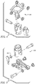
- FIG. 14A and 14B show perspective and bottom views of an exemplary sagittal moment load cell suitable for use in the various embodiments of the invention.
- Each joint actuation unit such as knee actuation unit 1302 and ankle actuation unit 1304 in FIG. 13A , can include a uniaxial load cell positioned in series with the actuation unit for closed loop force control. Both the knee and ankle joints can incorporate integrated potentiometers for joint angle position.
- the ankle actuation unit can include a spring 1305, as described above with respect to FIGs. 1A-4 .
- One 3-axis accelerometer can be located on the embedded system 1306 and a second one can located below the ankle joint 1308 on the ankle pivot member 1310.
- a strain based sagittal plane moment sensor 1312 such as sensor 1400 shown in FIGs.
- a sagittal plane moment sensor can be designed to have a low profile in order to accommodate longer residual limbs.
- the sensor can incorporate a full bridge of semiconductor strain gages which measure the strains generated by the sagittal plane moment.
- the sagittal plane moment sensor was calibrated for a measurement range of 100 Nm.
- a custom foot 1318 can designed to measure the ground reaction force components at the ball 1320 of the foot and heel 1322.
- the foot can include of heel and ball of foot beams, rigidly attached to a central fixture and arranged as cantilever beams with an arch that allows for the load to be localized at the heel and ball of the foot, respectively.
- Each heel and ball of foot beam can also incorporates a full bridge of semiconductor strain gages that measure the strains resulting from the respective ground contact forces.
- the heel and ball of foot load sensors were calibrated for a measurement range of 1000 N.
- incorporating the ground reaction load cell into the structure of a custom foot can eliminate the added weight of a separate load cell, and also enables separate measurement of the heel and ball of foot load.
- the prosthetic foot can be designed to be housed in a soft prosthetic foot shell (not shown).
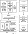
- the powered prostheses described above contain an embedded microcontroller that allows for either tethered or untethered operation.
- An exemplary embedded microcontroller system 1500 is shown in the block diagram in FIG. 15 .
- the embedded system 1500 consists of signal processing, power supply, power electronics, communications and computation modules.
- the system can be powered by a lithium polymer battery with 29.6 V.
- the signal electronics require +/- 12 V and +3.3 V, which are provided via linear regulators to maintain low noise levels.
- the battery voltage can be reduced by PWM switching amplifiers to +/- 15 V and +5 V prior to using the linear regulators.
- the power can be disconnected via a microcontroller that controls a solid state relay.
- the power status can be indicated by LED status indicators controlled also by the microcontroller.
- the analog sensor signals acquired by the embedded system include the prosthesis sensors signals (five strain gage signals and two potentiometer signals), analog reference signals from the laptop computer used for tethered operation, and signals measured on the board including battery current and voltage, knee and ankle servo amplifier currents and two 3-axis accelerometers.
- the prosthesis sensor signals are conditioned using input instrumentation amplifiers.
- the battery, knee motor and ankle motor currents are measured by current sense resistors and current sensing amplifiers.
- the signals are filtered with a first-order RC filter and buffered with high slew rate operational amplifiers before the analog to digital conversion stage.
- Analog to digital conversion can be accomplished by two 8-channel analog to digital convertors.
- the analog to digital conversion data can be transferred to the microcontroller via serial peripheral interface (SPI) bus.
- SPI serial peripheral interface
- the main computational element of the embedded system can be a 32-bit microcontroller.
- the microcontroller performs the servo and activity controllers of the prosthesis and data logging at each sample time.
- the prosthesis can also be controlled via a tether by a laptop computer running MATLAB Simulink RealTime Workshop.
- the microcontroller drives the servo amplifiers based on analog reference signals from the laptop computer.
- a memory card can be used for logging time-stamped data acquired from the sensors and recording internal controller information.
- the memory chip can be interfaced to the computer via wireless USB protocol.
- the microcontroller sends PWM reference signals to two four quadrant brushless DC motor drivers with regenerative capabilities in the second and forth quadrants of the velocity/torque curve.
- additional controls can be provided for operating the prosthesis when going from a sitting to a standing position or vice versa.
- This can be implemented via the use of a sitting mode controller implemented in the microcontroller.
- Operation of the sitting mode controller consists of four phases that are outlined in the general control state chart shown in FIG. 16 .
- two phases are primary sitting phases, weight bearing and non-weight bearing.
- the other two phases encompass the transition phases, pre-stand and pre-sit, for standing up and sitting down, respectively.
- Weight bearing and non-weight bearing are the primary sitting phases that switch the knee and ankle joints between high and low impedances, respectively.
- the transition phases, pre-stand and pre-sit modulate the stiffness of the knee as a function of knee angle, as shown in FIG. 17 , to assist the user in standing up and sitting down.
- FIG. 17 shows knee angle modulated knee stiffness during pre-stand (solid line) and pre-sit (dashed line) phases.
- the modulation allows for smoother transitions near the seated position.
- the ankle joint can be slightly dorsiflexed with moderate stiffness during the standing up and sitting down phases. Switching between the four sitting phases occurs when sensor thresholds are exceeded, as depicted FIG. 16 .
- the parameters of the impedance based controllers are tuned using a combination of feedback from the user and joint angle, torque and power data from the prosthesis.
- actuation for a prosthesis can be provided by two motor-driven ball screw assemblies that drive the knee and ankle joints, respectively, through a slider-crank linkage.
- the prosthesis can be capable of 120° of flexion at the knee and 45° of planterflexion and 20° of dorsiflexion at the ankle.
- each actuation unit consists of a DC motor (such as a Maxon EC30 Powermax) connected to a 12 mm diameter ball screw with 2 mm pitch, via helical shaft couplings.
- An exemplary ankle actuation unit additionally incorporates a 302 stainless steel spring (51mm free length and 35mm outer diameter), with 3 active coils and a stiffness of 385 N/cm in parallel with the ball screw.
- the purpose of the spring can be to bias the motor's axial force output toward ankle plantarflexion, and to supplement power output during ankle push off.
- the stiffness of the spring can be maximized to allow for peak force output without limiting the range of motion at the ankle.
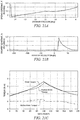
- the resulting axial actuation unit's force versus ankle angle plot can be shown in FIG. 18.
- FIG. 18 is a plot if axial force as a function of ankle angle illustrating spring force, actuator force and total force.
- FIG. 18 graphically demonstrates for fast walking the reduction in linear force output supplied by the motor at the ankle through the addition of the spring. Note that the compression spring does not engage until approximately five degrees of ankle plantarflexion.
- Each actuation unit can include a uniaxial load cell (such as Measurement Specialties ELPF-500L), positioned in series with the actuation unit for closed loop force control of the motor/ballscrew unit.
- Both the knee and ankle joints can incorporate bronze bearings and, for joint angle measurement, integrated precision potentiometers (such as an ALPS RDC503013).
- a strain based sagittal plane moment sensor as previously described with respect to FIGs. 14A and 14B can belocated between the knee joint and the socket connector, which measures the moment between the socket and prosthesis.
- the ankle joint connects to a foot, which incorporates strain gages to measure the ground reaction forces on the ball of the foot and on the heel.
- the central hollow structure houses a lithium-polymer battery and provides an attachment point for the embedded system hardware.
- the ankle joint can be placed slightly anterior to the centerline of the central structure. This gives the prosthesis the illusion of flexion when the amputee can be standing vertically with the knee fully extended.
- the length of the shank segment can be varied by changing the length of three components; the lower shank extension, the spring pull-down, and the coupler between the ball nut and ankle. Additional adjustability can be provided by the pyramid connector that can be integrated into the sagittal moment load cell for coupling the prosthesis to the socket (as is standard in commercial transfemoral prostheses).
- Passive joint torque can be defined as the part of the joint torque, ⁇ , which can be represented using spring and dashpot constitutional relationships (passive impedance behavior).
- the system can only store or dissipate energy due to this component.
- This active part can be represented as an algebraic function of the user input via the mechanical sensory interface (i.e socket interface forces and torques).
- Gait is considered a mainly periodic phenomena with the periods corresponding to the strides.
- the decomposition of a stride will give the required active and passive torque mappings for a specific activity mode.
- the joint behavior exhibits varying active and passive behavior in each stride. Therefore, segmenting of the stride in several parts can be necessary.
- decomposition of the torque over the entire stride period requires the decomposition of the different segments and piecewise reconstruction of the entire segment period.
- the segments cannot be divided arbitrarily, but rather can only be segmented when the stored energy in the passive elastic element is zero. This requires that the phase space can only be segmented when the joint angle begins and ends at the same value.
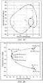
- Figure 19 shows the phase portrait of normal speed walking and the four different stride segments, S 1 , S 2 , S 3 , and S 4 .
- the entire decomposition process consists of first appropriate segmentation of the joint behavior, followed by the decomposition of each segment into its fundamental passive and active components.
- each segment shown in FIG. 19 can be converted to an optimization problem.
- 2n data points are selected by sampling the angular position in equal intervals between its minimum and maximum and selecting the corresponding positive and negative angular velocities.
- the number of angular position samples for each segment, n can be set to be 100.
- the constrained least squares optimization problem given in Equation 2 below can be constructed and solved. min x 1 2 ⁇ Cx ⁇ d ⁇ 2 2 s . t . 0 ⁇ x where C , x and d are defined in Equations 3, 4, and 5 below, respectively.
- the indexing of the joint angular position, angular velocity and moment samples are explained via the sketch in FIG. 20.
- FIG. 20 shows a selection and indexing of data samples from a first segment.
- X 4 n ⁇ 3 n C 1 C 2 C 3 T
- C 1 diag ⁇ 1 ⁇ 2 ⁇ ⁇ n n ⁇ 1 ⁇ ⁇ diag ⁇ n ⁇ n ⁇ 1 ⁇ ⁇ 1 n ⁇ 1 ⁇ ⁇ diag ⁇ ⁇ 1 ⁇ ⁇ 2 ⁇ ⁇ ⁇ ⁇ ⁇ ⁇ n 2 n ⁇ 1 2 n ⁇ 3 n
- C 2 C 21 C 22 C 23 2 n ⁇ 1 ⁇ 3 n
- the matrix C consists of three sub-matrices, C 1 , C 2 and C 3 .
- C 1 can be the main part responsible for the fitting of the spring and dashpot constants, k and b.
- C 2 bounds the rate of change of the passive joint torque and ensures smoothness in the resulting passive joint torque
- C 3 is basically a row of penalty constants, ⁇ , which penalizes large values of the spring and dashpot constants and thus limits the magnitudes of both.
- ⁇ is set to 0.1.
- each virtual spring can be also added to the optimization problem formulation as a parameter in order to obtain a tighter passive torque fit. Therefore, the optimization problem given by (3) can be solved iteratively for a range of values of spring origin constant, ⁇ .
- the solution with the least error norm can be selected as the optimal solution.
- FIG. 21 is the output of the decomposition for s 1 in FIG. 19 showing the spring and dashpot constants and the active and passive knee torques (Spring origin, ⁇ .is 23 degrees).
- the decomposed passive part can be very similar to the joint torque, and thus it can be stated that the behavior of the joint can be mainly passive.
- the result of the decomposition for the segments; can be stored in R i of the form given in Equation 6.
- the procedure presented above decomposes the joint torques into active and passive parts.
- the joint torque references for the control of the prosthesis are generated by combining this active and passive torques.
- a switching system modeling approach incorporating both discrete and continuous states can be used for the reconstruction of the torque reference signal.
- the state chart shown in FIG. 22 . will govern the discrete dynamics of the controller. Since the sequence of the segments can be ordered (i.e., the direction of the motion for a specific gait phase does not change), each segment can transition only to the next one, where the transition guard function can be written as a inequality in terms of ⁇ and ⁇ .
- the transitions between segments take no time and the dynamics of the controller are governed by the ⁇ ⁇ p i ( ⁇ , ⁇ ) ; ⁇ a i ( F S ) ⁇ pair at each sampling instant.
- the decomposition algorithm presented above gives the result matrix, R, for each segment.
- the discrete data in R can be used to construct the joint torque reference for the continuous measurements of another trial in the same gait phase.
- the Euclidian error norm between the [ ⁇ m ⁇ m ] T and the angular position and velocities of all the samples in that segment [ ⁇ i ⁇ i ] T can be calculated as shown in Equation 8 and stored in the vector e.
- the supervisory controller switches among different underlying intramodal controllers depending on the activity mode the user imposes on the prosthesis.
- the intent recognizer consists of three parts: activity mode recognizer, cadence estimator and the slope estimator.
- the activity mode recognizer detects the activity mode of the prosthesis (standing, walking, sitting, stair ascent or stair descent, etc). This can be accomplished by comparing the features which are generated in real time to a feature database using some machine learning and/or pattern recognition methods.
- the present implementation of the gait mode recognizer which recognizes standing and walking modes, is described below.
- a database which contains all the possible activity modes can be generated by making experimental trials.
- the user can be asked to walk or stand in different controller modes for 50 second long trials.
- the socket sagittal moment above the knee joint, foot heel load, foot ball load, knee angle, knee velocity, ankle angle and ankle velocity are recorded with 1 ms sampling period.
- other sensor signals such as accelerations and electromyography measurements from the residual limb can be added to the list of the signals used for intent recognition.
- 10000 random frames (5000 standing and 5000 walking) of 100 samples length are generated for all the seven recorded signals. The mean and the standard deviation of each frame are computed.
- the mean and standard deviation of signals are selected as the features since minimal computation can be required to obtain them.
- a database containing 10000 samples with 14 features (mean and standard deviation of the seven signals) belonging to two classes (standing and walking) can be generated.
- the dimension of the database can be reduced from 14 to three using principal component analysis (PCA).
- PCA principal component analysis
- Dimension reduction can be necessary because pattern recognition for high dimensional datasets can be computationally intensive for real-time applications.
- the standing and walking data can be modeled with Gaussian mixture models.
- Gaussian mixture models represent a probability distribution as a sum of several normal Gaussian distributions. The order of the Gaussian mixture model for each mode can be determined according to the Minimum Description Length Criteria.
- the database generation, dimension reduction and the Gaussian mixture modeling are explained.
- overlapping frames of 100 samples can be generated at each 10 ms interval.
- 14 features described above are extracted from these frames and the PCA dimension reduction can be applied to these features to get a reduced three dimensional feature vector.
- the reduced dimension features can be fed to the Gaussian mixture models for standing and walking and the probability of the sample vector being standing or walking can be computed.
- the mode with the greater probability is selected as the instantaneous activity mode. Since one decision might give wrong results in some cases due to noise, disturbance, etc..., a voting scheme can be used to enhance the results.
- the controller activity mode is switched if and only if more than 90 percent of the instantaneous activity mode decisions among the last 40 decisions are a specific activity mode. Once a new activity mode is selected by the voting scheme, the underlying activity controller can be switched to the corresponding mode.
- Such an activity mode recognizer is provided by way of illustration and not as a limitation.
- one or more parts of the algorithm might be modified.
- different features such as mean, max, kurtosis, median, AR coefficients, wavelet based features, frequency spectrum based features of the frame might be generated.
- different dimension reduction techniques such as linear discriminant analysis, independent component analysis might be employed.
- different classification methods such as artificial neural networks, support vector machines, decision trees, hidden Markov models might be used.
- Cadence estimation is accomplished by observing peak amplitudes in characteristic signal data and then measuring the time between successive peaks. Since walking is a cyclic activity each of the sensor signals will be periodic of cadence. The most relevant sensor signals will contain only one characteristic amplitude peak per stride such as foot heel load and the ball of foot load. In the real-time implementations, cadence estimation is accomplished by recording the foot load after heel strike when it exceeds 400 N until the load decreases below 350 N. Then, the time of occurrence of the peak load in this window is found and the previous peak time is subtracted from the new peak time. This corresponds to stride time and can be converted to cadence (steps/min) by multiplying with 120. Once the cadence is estimated, the intent recognizer selects the corresponding middle layer controller based on some predefined thresholds as in FIG. 23 .
- a 3D accelerometer capable of measuring ⁇ 3 g accelerations is embedded into the ankle joint coupler where the prosthetic foot is connected.
- An exemplary arrangement of such a system is shown by the schematic in FIG. 24 .
- the accelerometer measurements are used to estimate the ground slope.
- the accelerometer data in tangential direction is used.
- the ground slope angle, ⁇ s can be calculated as in equation (9) below.
- ⁇ s sin ⁇ 1 a t g
- g is the gravitational constant.
- the accelerometer data should be collected while the foot is flat on the ground as determined by the heel and ball of the foot load sensors. While the foot is flat on the ground, equation (1) is computed for the frame of the collected data and the mean of this frame is outputted as the ground slope estimate, ⁇ s .
- the intent recognizer selects the corresponding middle layer controller based on some predefined thresholds. An exemplary state chart for such an intent recognizer is shown in FIG. 25 .
- FIGs. 26A and 26B show front and back views of an exemplary embodiment of a friction drive transmission 2600 in accordance with an embodiment of the invention.
- the shaft 2602 of an electric motor 2604 is preloaded against a first stage in a housing 2606, such as a larger diameter cylinder or friction drive gear 2608, which creates sufficient friction to transmit torque without slip.
- the shaft 2602 can use one or more friction rollers 2610 to transmit the torque.
- the first stage of the friction drive can also be supplemented with a second stage.
- the friction drive gear 2608 drives a smooth pinion 2612 directly, which is preloaded against a larger diameter cylinder or cable gear output 2614 in the housing 2606, which in turn transmits torque directly to the knee or ankle joint.
- the first or second stage of the transmission can alternatively be embodied by a cable drive transmission, in which a cable is wrapped around the circumference of a larger diameter cylinder, such as friction drive gear 2608, and also around the circumference of a smaller diameter cylinder, such as pinion 2612.
- the cable is affixed to the friction drive gear 2608, and is pretensioned, using a tensioning screw 2616 or similar means, around both the drive gear 2608 and pinion 2612, such that friction between cable and pinion 2612 enables the transmission of torque from between the pinion 2612 and drive gear 2608.
- a combined friction drive/cable drive transmission can be used, in which a first stage of the transmission (i.e., the friction drive gear 2608 connected directly to the electric motor 2604) is of the friction drive type, while the second stage of the transmission (i.e., the cable gear output 2614 connected directly to the knee or ankle joint) is of the cable drive type.
- a first stage of the transmission i.e., the friction drive gear 2608 connected directly to the electric motor 2604
- the second stage of the transmission i.e., the cable gear output 2614 connected directly to the knee or ankle joint
- the prosthesis can incorporate a chain drive or a belt drive transmission embodiment for implementing one or more stages of a transmission.
- Advantages of a belt or chain drive approach over the ballscrew approaches described above include the ability to provide a fully enclosable/sealable (without need for a bellows-type cover) powered leg device. This facilitates component immersion in lubricating environment, and well as facilitating isolation from dirt, water, and other debris. As a result, this can extend the lifetime of transmission components.
- Another advantage of such a configuration is that it enables a greater range of motion of joint actuation, as opposed to a slider-crank mechanism (as used in a ballscrew configuration), which is generally limited.
- the belt or chain drive approach also allows the device to maintain a constant transmission ratio throughout range of motion, which is not generally possible in the slider-crank mechanism typically used in a ballscrew configuration.
- advantages of a belt or chain drive approach is that it maintains constant mechanism geometry throughout range of motion, belt and chain drive components are typically less expensive than ballscrew components, and belt and chain drive systems are typically characterized by lower audible noise than ballscrew configurations
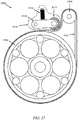
- FIG. 27 shows an exemplary embodiment of a belt drive transmission 2700 in accordance with an embodiment of the invention.
- a stage of the transmission 2700 can be embodied as a belt drive transmission, in which a belt 2702 is wrapped around the circumference of a larger diameter shaft, such as a first belt gear or pulley 2704, and also around the circumference of a smaller diameter shaft, such as second belt gear or pulley 2706.
- the belt 2702 can be tensioned, using a tensioning device 2708.
- the tensioning device 2708 can consist of a swing arm 2710, an additional pulley 2712 attached to the end of swing arm 2710, and tensioning screw 2714 for adjusting the swing arm 2710 to bias the additional pulley 2712 against the belt 2702, such that friction between the belt 2702 and belt gears 2704 and 2706 enables the transmission of torque from between second belt gear 2706 and first belt gear 2704.
- any other type of tensioning device can be used in the various embodiments to tension the belt 2702.
- the tensioning device 2708 can be a spring loaded device to automatically bias a pulley 2706 or other object against belt 2702 to cause the necessary tension.
- transmission 2700 is illustrated in terms of a V-belt embodiment, the invention is not limited in this regard and can be used with any type of belts.
- the belt 2702 can also be embodied as a flat belt, a round belt, a multi-groove belt, a ribbed belt, and a toothed or cog belt, to name a few.
- the belt gears 2704 and 2706 can be configured in accordance with the type of belt being used.
- a chain-based drive can be provided.
- the configuration in such embodiments can be substantially similar to that shown in FIG. 27 . That is, a chain can be provided in place of belt 2702 and gears 2704 and 2706 can be embodied as sprockets compatible with the chain.
- the tensioning device 2708 described above can still be utilized to maintain proper tension of the chain to enable the transmission of torque from between sprockets in the transmission.
- a pulley or sprocket can be configured with an eccentric mount. That is, configuring at least one of the drive gears in the transmission to allow an adjustment of its position. This is illustrated below with respect to FIGs. 28A-28D .
- FIGs. 28A and 28B show side views of first and second positions, respectively, achievable for an exemplary embodiment of a chain drive transmission 2800 including an eccentric mount in accordance with an embodiment of the invention. Similar to the transmission described above with respect to FIG. 27 , transmission 2800 includes a first shaft 2802 with first drive gears or sprockets 2804 and a second shaft 2806 with second drive gears or sprockets 2808 which can be coupled together via chains 2810 to transmit torques between sprockets 2804 and sprockets 2808.
- the first shaft 2802 is shown as including an additional sprocket 2812 for driving first shaft 2802.
- Such a configuration can be used when multiple drive stages are provided.
- the various embodiments are not limited in this regard.
- the first shaft 2802 is configured to be eccentric. That is, the position of the first shaft 2802 is adjustable relative to the position of the second shaft 2806 so as to adjust the lateral separation between the shafts (i.e., to provide d A ⁇ d B ). Accordingly, this also provides a means to adjust the tension in a chain (or a belt) between the first shaft 2802 and the second shaft 2806.
- the first shaft 2802 can be mounted in a leg device to an adjustable bearing mount 2814.
- the operation and configuration of an exemplary embodiment of the adjustable bearing mount 2814 is illustrated with respect to FIG. 29 .
- FIG. 29 illustrates schematically the components for the adjustable bearing mount 2812.
- the adjustable bearing mount 2814 can include a top plate 2902 to which first shaft 2802 is attached, a bottom plate 2904, bearings 2906 between the top plate 2902 and the bottom plate 2904, and fasteners 2908. These components of the adjustable bearing mount 2814 can be disposed within an enclosure 2910.
- the fasteners 2908 are shown as screws or bolts. However, the various embodiments are not limited to any particular bearing type or design of screws or bolts and other bearing types or designs can be used without limitation. Further, the various embodiments are not limited to screws or bolts and any other type of removable fastener can be used without limitation. Additionally, FIG. 29 shows bearings 2906 as a collection of ball bearings disposed between plates 2902 and 2904. However, the various embodiments are not limited to any particular bearing type or design and other bearing types or designs can be used without limitation.
- the enclosure 2910 can be configured such that when fasteners 2908 are loosened or removed, the bearings allow the top plate 2902 can be repositioned relative to the bottom plate 2904 via bearings 2906. Thus, when fasteners 2908 are replaced and tightened, the plates 2902 and 2904 are biased against bearings 2906 to prevent further motion of the top plate 2902 relative to the bottom plate 2904.
- Such a configuration allows adjustment of the position of first shaft 2802. For example, this can allow the first shaft 2802 to transition between a first position, as shown in FIG. 28A , in which a chain or belt 2810 with reduced tension is provided, due to a reduced distance (d A ) between first shaft 2802 and second shaft 2806, to a second position, as shown in FIG. 28B , in which a chain or belt 2814 with increased tension is provided, due to an increased distance (d B ) between first shaft 2802 and second shaft 2806.
- the various embodiments are not limited to solely first and second positions. Rather, in the various embodiments, the adjustable bear mount 2812 can be configured to allow a variety of positions for the first shaft 2806 relative to the second shaft 2806.
- FIG. 30 An exemplary configuration of a powered leg prosthesis 3000 in accordance with the discussion above is illustrated schematically in FIG. 30 .
- the powered leg prosthesis 3000 includes a shank 3002 with a powered knee joint 3004 and a powered ankle joint 3006.
- the powered knee joint 3004 includes a socket interface 3008 for attaching a socket 3010 or other device for attachment of the powered leg prosthesis 3000 to an amputee.
- the powered ankle joint 3006 can have a foot portion 3012 attached thereto.
- the shank 3002 can consist of a single, discrete unit. However, in some embodiments, the shank can include an upper portion 3014 and a lower portion 3016. Such a configuration allows the insertion of at least one extension unit 3018 to allow the length of the shank 3002 to be customized for the amputee.
- a belt or chain drive system can be implemented, as described above with respect to FIGs. 27-29 .
- the upper portion 3014 can include a first motor 3022, a first upper drive stage 3024, and a second upper drive stage 3026 for providing power at the powered knee joint 3004.
- the lower portion 3016 can include a second motor 3028, a first upper drive stage 3030, and a second upper drive stage 3032 for providing power at the powered ankle joint 3006.
- Each stage can consist of the belt or chain drive stage.
- each stage can be configured to include an eccentric mount, such as mounts 3034 and 3036, to adjust tension in the upper portion 3014 and lower portion 3016 respectively.
- the powered prosthetic leg 3000 can include other components not illustrated in FIG. 30 for purposes of clarity.
- the powered prosthetic leg can include a control system or device, as previously described, and one or more sensors throughout the powered prosthetic leg, also as previously described.
- control of the powered prosthetic leg 3000 can occur insubstantially the same manner as described above.
- the gait patterns seen in healthy humans navigating stairs and steps is fundamentally distinct from level ground walking.
- level ground walking Most notably, in biomechanically proper stair ascent the stance phase in the lower limb begins with significant knee flexion and ends near hyperextension. It is primarily this net knee extension during the stance phase that lifts the subject up the step. In healthy subjects this knee extension is not passive, rather the knee actively supplies a torque to lift the subject. Contrarily, in level ground walking the knee typically leaves stance slightly more flexed than when it entered, as the knee has already begun the flexing process that will continue through early swing. Additionally, the energetic behavior of the knee in the stance phase of level ground walking is primarily dissipative in nature, the opposite of the energetic behavior of the knee in stair ascent.
- a net knee flexion is typically seen in stair descent.
- This flexion allows the subject to lower his or her center of mass in anticipation of landing the contralateral foot on the subsequent step.
- the knee ends stance with more flexion than it enters stance during level ground walking the amount of net knee flexion is greater in stair descent.
- a more distinct difference between level ground walking and stair descent, however, can be seen in the ankle behavior during both swing and stance.
- the ankle At the end of swing the ankle actively plantarflexes in anticipation of a forefoot strike on the subsequent step. This preparatory plantarflexion decreases the single support phase by allowing the foot to strike the step sooner.
- the stance phase can be divided into a period of active knee extension, where the knee is delivering power to the user to lift him or her up the step, and then subsequently by a period of active ankle extension, where the ankle plantarflexes when the knee is straight and the user gains further height over the next step and the stance leg prepares for the knee flexion of the swing phase.
- the swing phase of the stair ascent can be divided into distinct periods of swing flexion and swing extension. These motions could be generated by emulating a passive impedance at each joint, but it is not integral to the invention to do so.
- An alternative strategy to achieve swing is to execute a predefined trajectory at the knee and/or ankle joint.
- the stance phase can be divided into a period of ankle yielding, where the ankle dissipates energy, and then subsequently by a period of knee yielding, where the knee dissipates energy.
- the swing phase for stair descent can be divided into distinct periods of swing flexion and swing extension. These motions could be generated by emulating a passive impedance at each joint, but it is not integral to the invention to do so.
- An alternative strategy to achieve swing is to execute a predefined trajectory at the knee and/or ankle joint.
- Cues can be based off of any sensor information available to the prosthesis, including, but not limited to: (1) estimating the location of a segment of the prosthesis or the user with respect to gravity through the use of inertial measurement; (2) joint angle or angular velocity measurements; (3) measurements of the degree of load or moment bearing in the prosthesis; and (4) direct input from the user, such as pressing a button or using a remote control.
- feedback regarding the activity mode can be provided.
- feedback can be provided to the user in the form of a tactile vibration from the prosthesis. This feedback can serve a variety of purposes with respect to informing the user of the decisions made by the control system.
- tactile feedback can be given upon entering either the stair ascent or stair descent portion of the controller in order to inform the user of this transition.
- the stair controller can be implemented using activity-level controllers in the form of a finite state machine (FSM).
- FSM finite state machine
- Each state within the FSM generates torque commands for the knee and ankle joints that ensure passivity within the state.
- ⁇ denotes the commanded torque
- ⁇ denotes the joint angle
- ⁇ denotes the joint angular velocity.
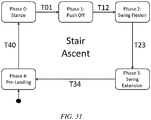
- the stair ascent controller consists of 5 phases, each of which is accessed sequentially in a single stride of stair ascent.
- the conditions for state transitions for stair ascent are listed in Table I, and the state machine is depicted in FIG. 31 .
- the knee is straightened and ankle push-off begins. Load is high Knee is straight Ankle is close to zero T12 Toe leaves the ground after pushing off. Load is low T23 Knee reaches maximum flexion in swing. Knee velocity inflects Knee exceeds a certain angle T34 Knee finishes extending and prepares for foot landing. Knee returns to proper angle T40 Ground contact is established and the next stride begins. Load is high
- Phase 4 which is called the pre-landing phase.
- the knee angle will generally be greater than zero.
- This phase is tuned for a relatively high impedance to prepare the prosthesis for loading once the user positions the prosthetic foot on the first step. This high impedance allows the user to register a load on the prosthesis even though the knee is relatively bent. The registration of this load triggers the T40 transition (Load > Threshold), and the prosthesis enters Phase 0.
- Phase 0 is the main power delivery phase of the stair ascent controller.
- the knee extends and lifts the center of mass of the user.
- the knee extension is achieved by selecting a high impedance for the knee and choosing an equilibrium position near zero (i.e., to begin straightening out the leg) such that the knee generates a large moment at the beginning of this phase.
- the transition from Phase 0 to Phase 1 (T01) occurs when the knee and ankle angles both straighten significantly (i.e., Knee angle ⁇ 0°, Ankle Angle ⁇ 0°, with respect to FIG. 7 ).
- This straightening is due in part to the extensive knee torque provided by the impedance set in Phase 0, and also by a simultaneous exertion of hip torque in flexion from the user. This torque coincides with ground contact on the contralateral side and is the signal for the ankle to start pushing off in preparation for swing.
- Phase 1 is characterized by ankle push-off, while a relatively high stiffness with an equilibrium position near zero is maintained at the knee.
- the transition from Phase 1 to Phase 2 (T12) occurs when ground contact is lost, as measured by a minimum threshold in the load sensor (Load ⁇ Threshold).
- the transitions T12 and T40 can be based on the same or different thresholds. Different thresholds can be provided since one transition is associated with loading (detected at the start of loading, which is a low level of load) and one transition is unloading (detected at a high level of load).
- Phase 2 is characterized by a large knee flexion produced by a moderate impedance and a non-zero knee equilibrium angle.
- the non-zero knee equilibrium angle in Phase 2 is provided to allow the prosthesis to clear the stair when swung.
- the transition from Phase 2 to Phase 3 (T23) then occurs when the knee velocity inflects during swing. In particular, after the knee angle passes its equilibrium position (Knee Angle > ⁇ eg ⁇ ).
- Phase 3 the swing extension phase, is characterized by a knee extension, while the ankle is maintained at or near a neutral or slightly dorsiflexed angle.
- the knee extension is achieved by selecting a low impedance for the knee and reducing the equilibrium position such that the knee generates a moment at the beginning of this phase.
- the ankle position is maintained by maintaining the previous set point and stiffness.
- the transition from Phase 3 to Phase 4 (T34) is then triggered once the knee has extended sufficiently (Knee Angle ⁇ ⁇ eg ).
- the stair descent controller is similar in form to the ascent controller, although with several significant differences in the nature of the finite states.
- the first major difference is that the lifting portion of the stance phase is replaced with a lowering portion as the user's center of mass moves down the steps.
- the second difference is that there is no push-off phase for the ankle; the small amount of swing flexion seen at the knee is actively provided by the knee actuator.
- the prosthesis enters stair descent in Phase 3, the swing extension phase.
- This phase is characterized by an extension of the knee to a zero equilibrium angle and a moderate impedance. Additionally, the ankle equilibrium position is selected such that the foot is substantially plantar-flexed in anticipation of ground contact.
- This phase serves both as the phase that extends the knee at the end of a stride and also as the pre-landing phase for the next instance of ground contact.
- the reason that the pre-landing phase and the knee extension phase are not distinct in the stair descent controller is because a high impedance is not necessary on ground contact, since the leg is preparing to yield to the weight of the user.
- the transition from Phase 3 to Phase 0 (T30) then occurs when a ground contact is established, as measured by the load cell or other load sensors on the prosthesis.
- the prosthesis enters the forefoot strike phase.
- This phase is characterized by a moderate impedance in the knee and a highly damped ankle.
- the ankle dorsiflexes in a highly damped manner under the load of the user, and acts to soften the impact of the user's heel with the stair. Since the ankle begins this phase in plantarflexion, it will now passively flex as the user loads the prosthesis. The transition from Phase 0 to Phase 1 (T01) will then occur when a threshold is met with respect to the ankle angle.
- Phase 1 the knee is highly damped, while the ankle remains damped. The result is a net knee flexion produced by the weight of the user, allowing him or her to descend the step. There is no push off phase after stance.
- T12 the transition from Phase 1 to Phase 2 (T12) occurs when ground contact is lost, as measured by a minimum threshold in the load sensor (Load ⁇ Threshold).
- Phase 2 is characterized by a large knee flexion produced by a moderate impedance and a non-zero knee equilibrium angle. Swing knee flexion is therefore active in this controller, although the amount of additional flexion after stance is minimal (just enough to enable the prosthesis to clear the step).
- the large knee equilibrium angle in Phase 2 is provided to allow the prosthesis to clear the stair when swung.
- the transition from Phase 2 to Phase 3 (T23) then occurs when the knee velocity inflects during swing. In particular, after the knee angle passes its equilibrium position (Knee Angle > ⁇ eg ⁇ ).
- Phase 3 the swing extension phase, is characterized by a knee extension and an active ankle plantarflexion.
- the knee extension is achieved by selecting a low impedance for the knee and reducing the equilibrium position such that the knee generates a moment at the beginning of this phase.
- the active ankle plantarflexion is achieved by setting a plantarflexed equilibrium position with a moderate amount of stiffness and damping.
- the controllers described above were implemented using a lower limb prosthesis similar to that described above with respect to FIGs. 30 .
- this lower limb prosthesis was configured to include knee and ankle actuators that are brushless DC motors, controlled by custom servo-amplifiers integrated into the embedded control system.
- Sensors in the prosthesis included a shank axial load sensor, angle sensors at the knee and ankle joints, and a 6-axis inertial measurement unit.
- the embedded electronics were contained on a single printed circuit board located on the shank of the prosthesis (excluding small circuit boards required for sensor interfacing).
- the power source was a lithium-polymer battery, and the prosthesis attaches to an amputee's socket with a standard pyramid connector.
- the current prototype can achieve approximately 100 Nm of torque at the ankle joint and 90 Nm of torque at the knee joint.
- the prosthesis prototype weighed approximately 4.3 kg (9.5 lb), not including the mass of the shoe or height adaptor shown.
- the stair ascent and descent control system was tested on a unilateral transfemoral amputee subject.
- the previously described impedance parameters were manually tuned for this subject in order to achieve appropriate stair ascent and descent behaviors.
- the amputee subject was a 23 year old man whose right side transfemoral amputation was the result of a traumatic injury.
- his daily use prosthesis was an Otto Bock C-Leg knee and a Freedom Innovations Renegade ankle/foot (i.e., a microprocessor-modulated damping knee, and a carbon fiber ankle/foot).
- kinematic data were also collected on 10 healthy male subjects with a mean age of 26.8 years (std. dev. 4.5 yrs.). Specifically, motion capture data were collected during both stair ascent and stair descent on a wooden 8-step staircase with 6.5" risers and 10" runners. Kinematic data were recorded with motion capture using a 12 camera Optitrack system from NaturalPoint. Marker data was collected at 120 Hz and converted to a skeletal model within NaturalPoint's ARENA software environment and exported as a BVH file resampled to 100 Hz. Sagittal plane joint angles were then extracted from the BVH files using MATLAB. Prior to testing, approval was received from the Vanderbilt University Institutional Review Board and all subjects gave informed consent, including permission for the publication of video and photographs.
- each subject ascended and descended the staircase in 10 trials.
- the second and third steps with each limb were used for analysis from each trial, totaling 20 strides for both ascent and descent for each subject.
- the same procedure was used for the amputee subject, although the use of a hand rail was allowed on the subject's sound side.
- trials were performed first with his daily use prosthesis (where he was instructed to attempt a step-over-step strategy for stair ascent, compensating for the lack of knee extensive torque with excessive hip extensive torque and by using the hand rail) and then with the powered prosthesis. It is important to note that the subject indicated that his preferred method of stair ascent with his daily-use prosthesis was to ascend each step with only his sound side.
- this method was selected for the comparison, since like the other cases (healthy and powered prosthesis), it represents step over step walking, and therefore arguably represents a fairer basis for comparison.
- the subject chose a strategy in which the prosthetic heel is placed approximately half a foot length from the edge of the step and the foot rolls over the edge of the step, effectively using the interface between the stair edge and foot as a proxy for the ankle joint.
- FIGs. 33 and 34 show the knee and ankle joint angles versus stride for stair ascent for the three experimental cases previously described.
- the top row shows the left and right average knee joint angle from the 10 healthy subjects, wherein each healthy subject dataset represents 20 strides, the middle row is the average left (intact) and right (prosthetic) knee joint angle over 20 strides from the amputee subject with the powered prosthesis and previously described stair ascent controller, and the bottom row is the average left (intact) and right (prosthetic) knee joint angle over 20 strides from the amputee subject with his daily use passive prosthesis. Since the ground reaction force was not measured in these experiments, mean curves for each healthy subject were computed by parsing the strides through manual selection of heel contact. This point was determined by the small but sharp inflection present in the ankle angle at heel strike.
- FIG. 34 The same plots for the ankle joint are shown in FIG. 34 . Since the powered prosthesis measures (and logs) the internally measured values for the knee and ankle angles, the mean curves corresponding to the joint angles measured internally in the prosthesis are also plotted as dashed lines on the subject's prosthetic side. Because ground contact is detected by a load threshold in the powered prosthesis, actual ground contact is made for some duration of time in the pre-landing phase (Phase 4) before the prosthesis transitions to Phase 0. As a result, a temporal offset was applied to the internal prosthesis signal to match the parsing of strides from the motion capture data.
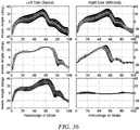
- Stair descent knee and ankle kinematics are shown in the same form as for stair ascent in FIGs. 35 and 36 (also for 20 strides in all plots, and for 10 subjects in the healthy subject case). Again the internal measure of the powered prosthesis knee and ankle angles are plotted in dashed lines on the appropriate plots. Another temporal offset was applied to the internal signals to account for a different load threshold in this controller. Since there is no significant push-off in stair descent, large ankle torques are not present, and consequently there is no discrepancy in the two ankle angle measurements.
- the knee angle of the powered prosthesis in stair ascent contains all the essential features of biomechanically normal stair ascent.
- the stance knee extension for the powered prosthesis appears slightly late relative to the healthy subject data.
- the amputee subject's sound side stance knee extension appears to occur earlier than in the healthy subject data. This asymmetry occurs due to a slight pause in the amputee subject's gait as he checks the position of the prosthetic foot on the step and prepares for the transition to Phase 0, the stance phase where the prosthetic knee extends.
- the ankle kinematics ( FIG. 34 ) for the powered prosthesis also exhibited similar trends to that of the healthy subjects, although there was less symmetry in this case between the amputee subject's sound and affected sides. Specifically there was a heightened plantarflexion of the sound side ankle, though its peak of -30° is still within approximately 2 standard deviations of the healthy subject data. This peak suggests some sound-side compensation when using the powered prosthesis, although the extent of (kinematic) compensation appears to be considerably less than when the subject used his daily-use prosthesis. Additionally the early portion of the stance phase of the sound ankle showed evidence of vaulting, as the ankle plantarflexes at 30% of stride instead of 60%.
- the subject's passive knee prosthesis is able to provide a high degree of functionality for this activity. Indeed, both the passive and powered knees provide fairly good facsimiles of healthy knee joint kinematics during stair descent. In both cases, however, there is a notable lack of early stance knee flexion (i.e., loading response) on the affected side. Although the framework of the powered prosthesis does allow for such stance knee flexion, the authors chose not to enable this feature, since it was effectively present via the compliance in the socket interface. An essential difference between the powered and the passive prostheses was the speed of stance knee flexion.
- the degree of damping in both the passive and powered prostheses can be adjusted (meaning that either one could be tuned to be faster or slower)
- the reason that the powered prosthesis exhibits a steeper knee flexion slope in descent is because the total descent in the powered prosthesis is split into two portions. In the first portion of stance the descent is due to ankle flexion (Phase 0). After the ankle has dorsiflexed sufficiently, the controller transitions to Phase 1 and the knee flexes, continuing the descent. This damped ankle flexion is impossible in the case of the passive carbon fiber ankle-foot complex because it cannot actively plantarflex in anticipation of a descending forefoot strike.
- a powered prosthesis with a stair ascent controller configured in accordance with the various embodiments provides knee and ankle joint kinematics during stair ascent that are considerably more reflective of healthy knee and ankle joint kinematics, relative to a passive prosthesis.
- experimental results of stair descent indicate that both passive prostheses and powered prostheses, configured in accordance with the various embodiments, provide appropriate knee joint kinematics during stair descent, while such powered prosthesis provides ankle joint kinematics considerably more reflective of healthy joint kinematics, relative to a passive ankle joint.
Claims (15)
- Ein Verfahren zum Bedienen einer unteren Gliedmaßenvorrichtung (100), die ein angetriebenes Kniegelenk (110) und ein angetriebenes Sprunggelenk (120) beinhaltet, wobei das Verfahren Folgendes beinhaltet:Konfigurieren der unteren Gliedmaßenvorrichtung zu einem Zustand eines endlichen Zustandsmodells für einen aktuellen Aktivitätsmodus, der aus einem von einer Vielzahl von Modi ausgewählt wird, wobei die Vielzahl von Aktivitätsmodi einen Treppenaufstiegsmodus beinhaltet;Umstellen der unteren Gliedmaßenvorrichtung, basierend auf Echtzeitsensorinformationen für die untere Gliedmaßenvorrichtung, von einem aktuellen Zustand auf einen nachfolgenden Zustand in dem endlichen Zustandsmodell des aktuellen Aktivitätsmodus, wenn ein vordefiniertes Kriterium zum Umstellen auf den nachfolgenden Zustand erfüllt ist;Umschalten des aktuellen Aktivitätsmodus in den oder von dem Treppenaufstiegsmodus, wenn mindestens eine von Orientierungs- oder Lageinformationen, die mit der unteren Gliedmaßenvorrichtung oder einem Nutzer der unteren Gliedmaßenvorrichtung in Zusammenhang stehen, Gelenkwinkel- oder Geschwindigkeitsmessungen für die untere Gliedmaßenvorrichtung oder Last- oder Momentmessungen für die untere Gliedmaßenvorrichtung einem vordefinierten Signal entspricht, um in den Treppenaufstiegsmodus einzutreten oder diesen zu verlassen; undWiederholen des Konfigurierens, des Umstellens und des Umschaltens, dadurch gekennzeichnet, dassdas endliche Zustandsmodell für den Treppenaufstiegsmodus eine Reihe von Zuständen beinhaltet, wobei die Reihe von Zuständen mindestens einen Hebezustand und mindestens einen Schwingzustand beinhaltet, wobei der mindestens eine Hebezustand eine angetriebene Kniestreckung und einen angetriebenen Sprunggelenksabstoß beinhaltet.
- Verfahren gemäß Anspruch 1, wobei der mindestens eine Hebezustand einen angetriebenen Kniebegradigungszustand und einen Sprunggelenksabstoß-Teilzustand beinhaltet, und wobei der mindestens eine Schwingzustand einen Kniebeugungszustand und einen Kniestreckungszustand beinhaltet.
- Verfahren gemäß Anspruch 1, wobei das Umstellen zwischen dem mindestens einen Hebezustand und dem mindestens einem Schwingzustand auf mindestens einer Lastmessung in der unteren Gliedmaßenvorrichtung basiert.
- Verfahren gemäß Anspruch 1, das ferner das Auswählen beinhaltet, dass als der aktuelle Aktivitätsmodus der Treppenaufstiegsmodus gewählt wird, wenn eine Schätzung einer Orientierung in Bezug auf die Schwerkraft für einen Oberschenkel, der mit dem angetriebenen Kniegelenk verbunden ist, eine Hüftstreckung über einen Zeitraum anzeigt.
- Verfahren gemäß Anspruch 1, das ferner das Auswählen beinhaltet, dass der Treppenaufstiegsmodus verlassen wird, wenn eine Schätzung einer Orientierung in Bezug auf die Schwerkraft für einen Oberschenkel, der mit dem angetriebenen Kniegelenk verbunden ist, ein Fehlen der Hüftbeugung über einen Zeitraum anzeigt.
- Verfahren gemäß Anspruch 1, das ferner das Auswählen beinhaltet, dass der aktuelle Aktivitätsmodus basierend auf einer direkten Eingabe von dem Nutzer in den oder von dem Treppenaufstiegsmodus gewechselt wird.
- Ein Verfahren zum Bedienen einer unteren Gliedmaßenvorrichtung (100), die ein angetriebenes Kniegelenk (110) und ein angetriebenes Sprunggelenk (120) beinhaltet, wobei das Verfahren Folgendes beinhaltet:Konfigurieren der unteren Gliedmaßenvorrichtung zu einem Zustand in einem endlichen Zustandsmodell für einen aktuellen Aktivitätsmodus, der aus einem von einer Vielzahl von Modi ausgewählt wird, wobei die Vielzahl von Aktivitätsmodi einen Treppenabstiegsmodus beinhaltet;Umstellen der unteren Gliedmaßenvorrichtung, basierend auf Echtzeitsensorinformationen für die untere Gliedmaßenvorrichtung, von einem aktuellen Zustand auf einen nachfolgenden Zustand in dem endlichen Zustandsmodell des aktuellen Aktivitätsmodus, wenn ein vordefiniertes Kriterium zum Umstellen auf den nachfolgenden Zustand erfüllt ist; undUmschalten des aktuellen Aktivitätsmodus in den oder von dem Treppenaufstiegsmodus, wenn mindestens eine von Orientierungs- oderLageinformationen, die mit der unteren Gliedmaßenvorrichtung oder einem Nutzer der unteren Gliedmaßenvorrichtung in Zusammenhang stehen, Gelenkwinkel- oder Geschwindigkeitsmessungen für die untere Gliedmaßenvorrichtung oder Last- oder Momentmessungen für die untere Gliedmaßenvorrichtung einem vordefinierten Signal entspricht, um in den Treppenaufstiegsmodus einzutreten oder diesen zu verlassen; undWiederholen des Konfigurierens, des Umstellens und des Umschaltens,dadurch gekennzeichnet, dassdas endliche Zustandsmodell für den Treppenabstiegsmodus eine Reihe von Zuständen beinhaltet, wobei die Reihe von Zuständen mindestens einen Nachgebezustand und mindestens einen Schwingzustand beinhaltet, wobei der mindestens eine Schwingzustand die Bereitstellung einer angetriebenen Plantarbeugung des angetriebenen Sprunggelenks beinhaltet, und wobei der mindestens eine Nachgebezustand die Bereitstellung einer Widerstands- und passiven Plantarbeugung des angetriebenen Sprunggelenks beinhaltet.
- Verfahren gemäß Anspruch 7, wobei der mindestens eine Nachgebezustand ferner die Bereitstellung einer Widerstands- und passiven Beugung des angetriebenen Kniegelenks beinhaltet.
- Verfahren gemäß Anspruch 7, wobei der mindestens eine Nachgebezustand einen Sprunggelenk-Dorsalbeugungszustand und einen Kniebeugungszustand beinhaltet, und wobei der mindestens eine Schwingzustand einen Kniebeugungszustand und einen Kniestreckungszustand beinhaltet.
- Verfahren gemäß Anspruch 7, wobei das Umstellen zwischen dem mindestens einen Nachgebezustand und dem mindestens einen Schwingzustand auf mindestens einer Lastmessung in der unteren Gliedmaßenvorrichtung basiert.
- Verfahren gemäß Anspruch 7, wobei das Umstellen zwischen mindestens einem Nachgebezustand und dem mindestens einen Schwingzustand auf mindestens einem Sprunggelenkswinkelmaß basiert.
- Verfahren gemäß Anspruch 7, das ferner Folgendes beinhaltet:
Auswählen, dass als der aktuelle Aktivitätsmodus der Treppenabstiegsmodus gewählt wird, wenn eine Schätzung der Orientierung des Oberschenkels des Nutzers in Bezug auf die Schwerkraft eine Hüftbeugung über einen Zeitraum anzeigt. - Verfahren gemäß Anspruch 7, das ferner Folgendes beinhaltet:
Auswählen, dass der Treppenabstiegsmodus verlassen wird, wenn eine Schätzung der Orientierung in Bezug auf die Schwerkraft für einen Oberschenkel, der mit dem angetriebenen Kniegelenk verbunden ist, das Fehlen der Hüftbeugung über einen Zeitraum anzeigt. - Ein computerlesbares Medium, das eine darauf gespeicherte Vielzahl von Anweisungen zum Bewirken, dass ein Computergerät ein beliebiges der Verfahren gemäß den Ansprüchen 1-13 durchführt, aufweist.
- Eine untere Gliedmaßenvorrichtung (100), die ein angetriebenes Kniegelenk (110) und ein angetriebenes Sprunggelenk (120) beinhaltet, die Folgendes beinhaltet:mindestens einen Sensor (125, 135, 140, 141, 142, 151, 152) zum Erzeugen von Echtzeitsensorinformationen für die untere Gliedmaßenvorrichtung;mindestens einen Prozessor, der kommunikativ mit dem mindestens einen Sensor, dem angetriebenen Kniegelenk und dem angetriebenen Sprunggelenk gekoppelt ist; undein computerlesbares Medium, das darauf gespeicherte Anweisungen zum Bewirken, dass der mindestens eine Prozessor ein beliebiges der Verfahren gemäß den Ansprüchen 1-13 durchführt, aufweist.
Applications Claiming Priority (2)
| Application Number | Priority Date | Filing Date | Title |
|---|---|---|---|
| US201261647369P | 2012-05-15 | 2012-05-15 | |
| PCT/US2013/031849 WO2013172968A1 (en) | 2012-05-15 | 2013-03-15 | Stair ascent and descent control for powered lower limb devices |
Publications (2)
| Publication Number | Publication Date |
|---|---|
| EP2849687A1 EP2849687A1 (de) | 2015-03-25 |
| EP2849687B1 true EP2849687B1 (de) | 2018-07-18 |
Family
ID=48045079
Family Applications (1)
| Application Number | Title | Priority Date | Filing Date |
|---|---|---|---|
| EP13713653.7A Active EP2849687B1 (de) | 2012-05-15 | 2013-03-15 | Treppenaufstiegs- und abstiegssteuerung für angetriebene untere gliedmassenvorrichtungen |
Country Status (3)
| Country | Link |
|---|---|
| US (3) | US10441439B2 (de) |
| EP (1) | EP2849687B1 (de) |
| WO (1) | WO2013172968A1 (de) |
Cited By (1)
| Publication number | Priority date | Publication date | Assignee | Title |
|---|---|---|---|---|
| DE102019121234B3 (de) * | 2019-08-06 | 2021-01-07 | Ottobock Se & Co. Kgaa | Orthopädietechnische Vorrichtung |
Families Citing this family (31)
| Publication number | Priority date | Publication date | Assignee | Title |
|---|---|---|---|---|
| EP2104475B1 (de) | 2007-01-05 | 2016-03-09 | Victhom Human Bionics Inc. | Gelenkbetätigungsmechanismus für eine prothesen- und/oder orthosenvorrichtung mit entsprechender übersetzung |
| CA2676067C (en) | 2007-01-19 | 2017-06-20 | Victhom Human Bionics, Inc. | Reactive layer control system for prosthetic and orthotic devices |
| US9180025B2 (en) * | 2008-04-21 | 2015-11-10 | Vanderbilt University | Powered leg prosthesis and control methodologies for obtaining near normal gait |
| US9060884B2 (en) | 2011-05-03 | 2015-06-23 | Victhom Human Bionics Inc. | Impedance simulating motion controller for orthotic and prosthetic applications |
| US9044346B2 (en) | 2012-03-29 | 2015-06-02 | össur hf | Powered prosthetic hip joint |
| GB201302025D0 (en) | 2013-02-05 | 2013-03-20 | Touch Emas Ltd | Improvements in or relating to prosthetics |
| US9561118B2 (en) | 2013-02-26 | 2017-02-07 | össur hf | Prosthetic foot with enhanced stability and elastic energy return |
| US9028557B2 (en) | 2013-03-14 | 2015-05-12 | Freedom Innovations, Llc | Prosthetic with voice coil valve |
| WO2014159114A1 (en) | 2013-03-14 | 2014-10-02 | össur hf | Prosthetic ankle: a method of controlling based on adaptation to speed |
| US9849002B2 (en) | 2013-08-27 | 2017-12-26 | Freedom Innovations, Llc | Microprocessor controlled prosthetic ankle system for footwear and terrain adaptation |
| US10369023B2 (en) * | 2013-11-01 | 2019-08-06 | Rehabilitation Institute Of Chicago | Impedance parameter power control for lower limb assistive device |
| EP3102158B1 (de) | 2014-02-04 | 2019-06-12 | Rehabilitation Institute of Chicago | Modulare und leichte myoelektrische prothese |
| GB201403265D0 (en) * | 2014-02-25 | 2014-04-09 | Touch Emas Ltd | Prosthetic digit for use with touchscreen devices |
| JP5989694B2 (ja) * | 2014-03-07 | 2016-09-07 | 国立大学法人 東京大学 | 制御装置、制御方法及び制御プログラム |
| WO2015157723A1 (en) | 2014-04-11 | 2015-10-15 | össur hf | Prosthetic foot with removable flexible members |
| US10531968B2 (en) | 2014-05-23 | 2020-01-14 | Joseph Coggins | Prosthetic limb test apparatus and method |
| GB201417541D0 (en) | 2014-10-03 | 2014-11-19 | Touch Bionics Ltd | Wrist device for a prosthetic limb |
| US10792170B2 (en) * | 2015-02-12 | 2020-10-06 | Board Of Regents, The University Of Texas Systems | Systems and methods for prosthetic device control |
| DE102015106392B4 (de) * | 2015-04-24 | 2020-07-09 | Otto Bock Healthcare Products Gmbh | Verfahren zur Steuerung der Standphasendämpfung eines künstlichen Kniegelenks |
| CN105798932B (zh) * | 2016-05-19 | 2017-10-13 | 成都润惠科技有限公司 | 一种用于外骨骼系统行走状态的控制方法 |
| US11185426B2 (en) | 2016-09-02 | 2021-11-30 | Touch Bionics Limited | Systems and methods for prosthetic wrist rotation |
| US10973660B2 (en) | 2017-12-15 | 2021-04-13 | Touch Bionics Limited | Powered prosthetic thumb |
| DE102018100252A1 (de) | 2018-01-08 | 2019-07-11 | Otto Bock Healthcare Products Gmbh | Orthopädietechnische Vorrichtung |
| US11471306B2 (en) | 2018-01-25 | 2022-10-18 | Vanderbilt University | Prosthetic knee with swing assist |
| WO2019177022A1 (ja) * | 2018-03-13 | 2019-09-19 | BionicM株式会社 | 補助装置およびその制御方法 |
| WO2020086721A2 (en) * | 2018-10-23 | 2020-04-30 | Massachusetts Institute Of Technology | Neural efferent and afferent control of spring equilibrium, damping, and power in backdrivable and non-backdrivable series-elastic actuators comprising variable series stiffness mechanisms |
| KR20200072203A (ko) * | 2018-12-12 | 2020-06-22 | 삼성전자주식회사 | 링크 어셈블리 및 이를 포함하는 운동 보조 장치 |
| EP4032508A4 (de) * | 2019-09-17 | 2023-09-27 | Bionicm Inc. | Assistenzvorrichtung und künstliches gliedmass |
| US11931270B2 (en) | 2019-11-15 | 2024-03-19 | Touch Bionics Limited | Prosthetic digit actuator |
| CN111110409B (zh) * | 2020-01-16 | 2022-03-25 | 上海理工大学 | 一种主被动混合驱动智能假肢膝关节结构 |
| TR202022508A2 (tr) * | 2020-12-30 | 2022-07-21 | Oezyegin Ueniversitesi | Yürüme, oturma-kalkma, merdiven tırmanışı için bir transfemoral protez. |
Family Cites Families (21)
| Publication number | Priority date | Publication date | Assignee | Title |
|---|---|---|---|---|
| US4685925A (en) * | 1984-10-22 | 1987-08-11 | Northwestern University | Voluntary opening prehension device |
| GB2216426B (en) | 1988-03-25 | 1992-09-30 | Kobe Steel Ltd | Programmable leg prosthesis |
| CA2057108C (en) * | 1991-12-05 | 1996-12-31 | Kelvin B. James | System for controlling artificial knee joint action in an above knee prosthesis |
| GB9813904D0 (en) * | 1997-08-15 | 1998-08-26 | Blatchford & Sons Ltd | A lower limb prosthesis |
| AU2004226596C1 (en) * | 2003-04-02 | 2010-09-16 | Neurostream Technologies General Partnership | Implantable nerve signal sensing and stimulation device for treating foot drop and other neurological disorders |
| US8057550B2 (en) * | 2004-02-12 | 2011-11-15 | össur hf. | Transfemoral prosthetic systems and methods for operating the same |
| CN1984623B (zh) * | 2004-03-10 | 2011-04-13 | 奥瑟Hf公司 | 用于义膝的控制系统和方法 |
| US7393335B2 (en) * | 2004-05-06 | 2008-07-01 | Carvey Matthew R | Metabolically efficient leg brace |
| US8512415B2 (en) * | 2005-03-31 | 2013-08-20 | Massachusetts Institute Of Technology | Powered ankle-foot prothesis |
| WO2006113520A2 (en) * | 2005-04-13 | 2006-10-26 | The Regents Of The University Of California | Semi-powered lower extremity exoskeleton |
| US7485152B2 (en) * | 2005-08-26 | 2009-02-03 | The Ohio Willow Wood Company | Prosthetic leg having electronically controlled prosthetic knee with regenerative braking feature |
| DE102006021802A1 (de) * | 2006-05-09 | 2007-11-15 | Otto Bock Healthcare Ip Gmbh & Co. Kg | Steuerung eines passiven Prothesenkniegelenkes mit verstellbarer Dämpfung |
| US8652218B2 (en) * | 2008-04-21 | 2014-02-18 | Vanderbilt University | Powered leg prosthesis and control methodologies for obtaining near normal gait |
| WO2010005473A1 (en) | 2008-06-16 | 2010-01-14 | Berkeley Bionics | Semi-actuated transfemoral prosthetic knee |
| EP2349120B1 (de) * | 2008-09-04 | 2017-03-22 | Iwalk, Inc. | Hybride untergrund-adaptierende systeme für beinprothesen, -orthesen sowie -exoskelettvorrichtungen |
| KR20110120927A (ko) * | 2009-01-30 | 2011-11-04 | 메사추세츠 인스티튜트 오브 테크놀로지 | 주동근-길항근 작용을 구비한 능동형 인공 무릎 |
| DE102009052894A1 (de) * | 2009-11-13 | 2011-06-01 | Otto Bock Healthcare Products Gmbh | Verfahren und Vorrichtung zur Steuerung eines künstlichen orthetischen oder prothetischen Gelenkes |
| WO2012044621A1 (en) * | 2010-09-27 | 2012-04-05 | Vanderbilt University | Movement assistance device |
| CA2812955C (en) * | 2010-09-29 | 2018-09-04 | Ossur Hf | Prosthetic and orthotic devices and methods and systems for controlling the same |
| WO2012096956A1 (en) * | 2011-01-10 | 2012-07-19 | Iwalk, Inc. | Powered joint orthosis |
| US9687377B2 (en) * | 2011-01-21 | 2017-06-27 | Bionx Medical Technologies, Inc. | Terrain adaptive powered joint orthosis |
-
2013
- 2013-03-15 US US13/832,431 patent/US10441439B2/en active Active
- 2013-03-15 EP EP13713653.7A patent/EP2849687B1/de active Active
- 2013-03-15 WO PCT/US2013/031849 patent/WO2013172968A1/en active Application Filing
-
2019
- 2019-07-03 US US16/502,914 patent/US11173054B2/en active Active
-
2021
- 2021-10-12 US US17/499,287 patent/US11666463B2/en active Active
Non-Patent Citations (1)
| Title |
|---|
| None * |
Cited By (1)
| Publication number | Priority date | Publication date | Assignee | Title |
|---|---|---|---|---|
| DE102019121234B3 (de) * | 2019-08-06 | 2021-01-07 | Ottobock Se & Co. Kgaa | Orthopädietechnische Vorrichtung |
Also Published As
| Publication number | Publication date |
|---|---|
| US20190388247A1 (en) | 2019-12-26 |
| US10441439B2 (en) | 2019-10-15 |
| US11666463B2 (en) | 2023-06-06 |
| EP2849687A1 (de) | 2015-03-25 |
| WO2013172968A1 (en) | 2013-11-21 |
| US20220054285A1 (en) | 2022-02-24 |
| US20130310949A1 (en) | 2013-11-21 |
| US11173054B2 (en) | 2021-11-16 |
Similar Documents
| Publication | Publication Date | Title |
|---|---|---|
| US11666463B2 (en) | Stair descent control for powered lower limb devices | |
| US11318028B2 (en) | System and method for providing biomechanically suitable running gait in powered lower limb devices | |
| US10639169B2 (en) | Powered leg prosthesis and control methodologies for obtaining near normal gait | |
| US10137010B2 (en) | Coordinating operation of multiple lower limb devices | |
| US9289315B2 (en) | Powered leg prosthesis and control methodologies for obtaining near normal gait | |
| US11278433B2 (en) | Powered ankle-foot prosthesis | |
| Sup et al. | Preliminary evaluations of a self-contained anthropomorphic transfemoral prosthesis | |
| Lenzi et al. | Design, development, and validation of a lightweight nonbackdrivable robotic ankle prosthesis | |
| Hoover et al. | Stair ascent with a powered transfemoral prosthesis under direct myoelectric control | |
| US8512415B2 (en) | Powered ankle-foot prothesis | |
| JP2012516717A (ja) | 作動筋−拮抗筋作用を有する動力付き人工膝 | |
| Lawson | Control methodologies for powered prosthetic interventions in unilateral and bilateral transfemoral amputees | |
| Shirsath et al. | Neural network based gait phases of above knee prosthesis | |
| Varol | Supervisory control and intent recognition of a powered knee and ankle prosthesis | |
| Sup et al. | Manuscript 2: Preliminary Evaluations of a Self-Contained Anthropomorphic Transfemoral Prosthesis |
Legal Events
| Date | Code | Title | Description |
|---|---|---|---|
| PUAI | Public reference made under article 153(3) epc to a published international application that has entered the european phase |
Free format text: ORIGINAL CODE: 0009012 |
|
| 17P | Request for examination filed |
Effective date: 20141210 |
|
| AK | Designated contracting states |
Kind code of ref document: A1 Designated state(s): AL AT BE BG CH CY CZ DE DK EE ES FI FR GB GR HR HU IE IS IT LI LT LU LV MC MK MT NL NO PL PT RO RS SE SI SK SM TR |
|
| AX | Request for extension of the european patent |
Extension state: BA ME |
|
| DAX | Request for extension of the european patent (deleted) | ||
| 17Q | First examination report despatched |
Effective date: 20160504 |
|
| STAA | Information on the status of an ep patent application or granted ep patent |
Free format text: STATUS: EXAMINATION IS IN PROGRESS |
|
| GRAP | Despatch of communication of intention to grant a patent |
Free format text: ORIGINAL CODE: EPIDOSNIGR1 |
|
| STAA | Information on the status of an ep patent application or granted ep patent |
Free format text: STATUS: GRANT OF PATENT IS INTENDED |
|
| INTG | Intention to grant announced |
Effective date: 20180105 |
|
| GRAS | Grant fee paid |
Free format text: ORIGINAL CODE: EPIDOSNIGR3 |
|
| GRAJ | Information related to disapproval of communication of intention to grant by the applicant or resumption of examination proceedings by the epo deleted |
Free format text: ORIGINAL CODE: EPIDOSDIGR1 |
|
| GRAL | Information related to payment of fee for publishing/printing deleted |
Free format text: ORIGINAL CODE: EPIDOSDIGR3 |
|
| STAA | Information on the status of an ep patent application or granted ep patent |
Free format text: STATUS: EXAMINATION IS IN PROGRESS |
|
| GRAR | Information related to intention to grant a patent recorded |
Free format text: ORIGINAL CODE: EPIDOSNIGR71 |
|
| STAA | Information on the status of an ep patent application or granted ep patent |
Free format text: STATUS: GRANT OF PATENT IS INTENDED |
|
| GRAA | (expected) grant |
Free format text: ORIGINAL CODE: 0009210 |
|
| STAA | Information on the status of an ep patent application or granted ep patent |
Free format text: STATUS: THE PATENT HAS BEEN GRANTED |
|
| INTC | Intention to grant announced (deleted) | ||
| AK | Designated contracting states |
Kind code of ref document: B1 Designated state(s): AL AT BE BG CH CY CZ DE DK EE ES FI FR GB GR HR HU IE IS IT LI LT LU LV MC MK MT NL NO PL PT RO RS SE SI SK SM TR |
|
| INTG | Intention to grant announced |
Effective date: 20180612 |
|
| REG | Reference to a national code |
Ref country code: GB Ref legal event code: FG4D |
|
| REG | Reference to a national code |
Ref country code: CH Ref legal event code: EP |
|
| REG | Reference to a national code |
Ref country code: IE Ref legal event code: FG4D |
|
| REG | Reference to a national code |
Ref country code: AT Ref legal event code: REF Ref document number: 1018557 Country of ref document: AT Kind code of ref document: T Effective date: 20180815 |
|
| REG | Reference to a national code |
Ref country code: DE Ref legal event code: R096 Ref document number: 602013040420 Country of ref document: DE |
|
| REG | Reference to a national code |
Ref country code: NL Ref legal event code: MP Effective date: 20180718 |
|
| REG | Reference to a national code |
Ref country code: LT Ref legal event code: MG4D |
|
| REG | Reference to a national code |
Ref country code: AT Ref legal event code: MK05 Ref document number: 1018557 Country of ref document: AT Kind code of ref document: T Effective date: 20180718 |
|
| PG25 | Lapsed in a contracting state [announced via postgrant information from national office to epo] |
Ref country code: NL Free format text: LAPSE BECAUSE OF FAILURE TO SUBMIT A TRANSLATION OF THE DESCRIPTION OR TO PAY THE FEE WITHIN THE PRESCRIBED TIME-LIMIT Effective date: 20180718 |
|
| PG25 | Lapsed in a contracting state [announced via postgrant information from national office to epo] |
Ref country code: NO Free format text: LAPSE BECAUSE OF FAILURE TO SUBMIT A TRANSLATION OF THE DESCRIPTION OR TO PAY THE FEE WITHIN THE PRESCRIBED TIME-LIMIT Effective date: 20181018 Ref country code: GR Free format text: LAPSE BECAUSE OF FAILURE TO SUBMIT A TRANSLATION OF THE DESCRIPTION OR TO PAY THE FEE WITHIN THE PRESCRIBED TIME-LIMIT Effective date: 20181019 Ref country code: AT Free format text: LAPSE BECAUSE OF FAILURE TO SUBMIT A TRANSLATION OF THE DESCRIPTION OR TO PAY THE FEE WITHIN THE PRESCRIBED TIME-LIMIT Effective date: 20180718 Ref country code: BG Free format text: LAPSE BECAUSE OF FAILURE TO SUBMIT A TRANSLATION OF THE DESCRIPTION OR TO PAY THE FEE WITHIN THE PRESCRIBED TIME-LIMIT Effective date: 20181018 Ref country code: FI Free format text: LAPSE BECAUSE OF FAILURE TO SUBMIT A TRANSLATION OF THE DESCRIPTION OR TO PAY THE FEE WITHIN THE PRESCRIBED TIME-LIMIT Effective date: 20180718 Ref country code: LT Free format text: LAPSE BECAUSE OF FAILURE TO SUBMIT A TRANSLATION OF THE DESCRIPTION OR TO PAY THE FEE WITHIN THE PRESCRIBED TIME-LIMIT Effective date: 20180718 Ref country code: RS Free format text: LAPSE BECAUSE OF FAILURE TO SUBMIT A TRANSLATION OF THE DESCRIPTION OR TO PAY THE FEE WITHIN THE PRESCRIBED TIME-LIMIT Effective date: 20180718 Ref country code: PL Free format text: LAPSE BECAUSE OF FAILURE TO SUBMIT A TRANSLATION OF THE DESCRIPTION OR TO PAY THE FEE WITHIN THE PRESCRIBED TIME-LIMIT Effective date: 20180718 Ref country code: IS Free format text: LAPSE BECAUSE OF FAILURE TO SUBMIT A TRANSLATION OF THE DESCRIPTION OR TO PAY THE FEE WITHIN THE PRESCRIBED TIME-LIMIT Effective date: 20181118 Ref country code: SE Free format text: LAPSE BECAUSE OF FAILURE TO SUBMIT A TRANSLATION OF THE DESCRIPTION OR TO PAY THE FEE WITHIN THE PRESCRIBED TIME-LIMIT Effective date: 20180718 |
|
| PG25 | Lapsed in a contracting state [announced via postgrant information from national office to epo] |
Ref country code: AL Free format text: LAPSE BECAUSE OF FAILURE TO SUBMIT A TRANSLATION OF THE DESCRIPTION OR TO PAY THE FEE WITHIN THE PRESCRIBED TIME-LIMIT Effective date: 20180718 Ref country code: LV Free format text: LAPSE BECAUSE OF FAILURE TO SUBMIT A TRANSLATION OF THE DESCRIPTION OR TO PAY THE FEE WITHIN THE PRESCRIBED TIME-LIMIT Effective date: 20180718 Ref country code: HR Free format text: LAPSE BECAUSE OF FAILURE TO SUBMIT A TRANSLATION OF THE DESCRIPTION OR TO PAY THE FEE WITHIN THE PRESCRIBED TIME-LIMIT Effective date: 20180718 |
|
| REG | Reference to a national code |
Ref country code: DE Ref legal event code: R097 Ref document number: 602013040420 Country of ref document: DE |
|
| PG25 | Lapsed in a contracting state [announced via postgrant information from national office to epo] |
Ref country code: EE Free format text: LAPSE BECAUSE OF FAILURE TO SUBMIT A TRANSLATION OF THE DESCRIPTION OR TO PAY THE FEE WITHIN THE PRESCRIBED TIME-LIMIT Effective date: 20180718 Ref country code: IT Free format text: LAPSE BECAUSE OF FAILURE TO SUBMIT A TRANSLATION OF THE DESCRIPTION OR TO PAY THE FEE WITHIN THE PRESCRIBED TIME-LIMIT Effective date: 20180718 Ref country code: ES Free format text: LAPSE BECAUSE OF FAILURE TO SUBMIT A TRANSLATION OF THE DESCRIPTION OR TO PAY THE FEE WITHIN THE PRESCRIBED TIME-LIMIT Effective date: 20180718 Ref country code: CZ Free format text: LAPSE BECAUSE OF FAILURE TO SUBMIT A TRANSLATION OF THE DESCRIPTION OR TO PAY THE FEE WITHIN THE PRESCRIBED TIME-LIMIT Effective date: 20180718 Ref country code: RO Free format text: LAPSE BECAUSE OF FAILURE TO SUBMIT A TRANSLATION OF THE DESCRIPTION OR TO PAY THE FEE WITHIN THE PRESCRIBED TIME-LIMIT Effective date: 20180718 |
|
| PLBE | No opposition filed within time limit |
Free format text: ORIGINAL CODE: 0009261 |
|
| STAA | Information on the status of an ep patent application or granted ep patent |
Free format text: STATUS: NO OPPOSITION FILED WITHIN TIME LIMIT |
|
| PG25 | Lapsed in a contracting state [announced via postgrant information from national office to epo] |
Ref country code: SK Free format text: LAPSE BECAUSE OF FAILURE TO SUBMIT A TRANSLATION OF THE DESCRIPTION OR TO PAY THE FEE WITHIN THE PRESCRIBED TIME-LIMIT Effective date: 20180718 Ref country code: SM Free format text: LAPSE BECAUSE OF FAILURE TO SUBMIT A TRANSLATION OF THE DESCRIPTION OR TO PAY THE FEE WITHIN THE PRESCRIBED TIME-LIMIT Effective date: 20180718 Ref country code: DK Free format text: LAPSE BECAUSE OF FAILURE TO SUBMIT A TRANSLATION OF THE DESCRIPTION OR TO PAY THE FEE WITHIN THE PRESCRIBED TIME-LIMIT Effective date: 20180718 |
|
| 26N | No opposition filed |
Effective date: 20190423 |
|
| PG25 | Lapsed in a contracting state [announced via postgrant information from national office to epo] |
Ref country code: SI Free format text: LAPSE BECAUSE OF FAILURE TO SUBMIT A TRANSLATION OF THE DESCRIPTION OR TO PAY THE FEE WITHIN THE PRESCRIBED TIME-LIMIT Effective date: 20180718 |
|
| PG25 | Lapsed in a contracting state [announced via postgrant information from national office to epo] |
Ref country code: MC Free format text: LAPSE BECAUSE OF FAILURE TO SUBMIT A TRANSLATION OF THE DESCRIPTION OR TO PAY THE FEE WITHIN THE PRESCRIBED TIME-LIMIT Effective date: 20180718 |
|
| REG | Reference to a national code |
Ref country code: CH Ref legal event code: PL |
|
| GBPC | Gb: european patent ceased through non-payment of renewal fee |
Effective date: 20190315 |
|
| PG25 | Lapsed in a contracting state [announced via postgrant information from national office to epo] |
Ref country code: LU Free format text: LAPSE BECAUSE OF NON-PAYMENT OF DUE FEES Effective date: 20190315 |
|
| REG | Reference to a national code |
Ref country code: BE Ref legal event code: MM Effective date: 20190331 |
|
| PG25 | Lapsed in a contracting state [announced via postgrant information from national office to epo] |
Ref country code: GB Free format text: LAPSE BECAUSE OF NON-PAYMENT OF DUE FEES Effective date: 20190315 Ref country code: LI Free format text: LAPSE BECAUSE OF NON-PAYMENT OF DUE FEES Effective date: 20190331 Ref country code: CH Free format text: LAPSE BECAUSE OF NON-PAYMENT OF DUE FEES Effective date: 20190331 Ref country code: IE Free format text: LAPSE BECAUSE OF NON-PAYMENT OF DUE FEES Effective date: 20190315 |
|
| PG25 | Lapsed in a contracting state [announced via postgrant information from national office to epo] |
Ref country code: FR Free format text: LAPSE BECAUSE OF NON-PAYMENT OF DUE FEES Effective date: 20190331 Ref country code: BE Free format text: LAPSE BECAUSE OF NON-PAYMENT OF DUE FEES Effective date: 20190331 |
|
| PG25 | Lapsed in a contracting state [announced via postgrant information from national office to epo] |
Ref country code: TR Free format text: LAPSE BECAUSE OF FAILURE TO SUBMIT A TRANSLATION OF THE DESCRIPTION OR TO PAY THE FEE WITHIN THE PRESCRIBED TIME-LIMIT Effective date: 20180718 |
|
| PG25 | Lapsed in a contracting state [announced via postgrant information from national office to epo] |
Ref country code: MT Free format text: LAPSE BECAUSE OF NON-PAYMENT OF DUE FEES Effective date: 20190315 Ref country code: PT Free format text: LAPSE BECAUSE OF FAILURE TO SUBMIT A TRANSLATION OF THE DESCRIPTION OR TO PAY THE FEE WITHIN THE PRESCRIBED TIME-LIMIT Effective date: 20181118 |
|
| PG25 | Lapsed in a contracting state [announced via postgrant information from national office to epo] |
Ref country code: CY Free format text: LAPSE BECAUSE OF FAILURE TO SUBMIT A TRANSLATION OF THE DESCRIPTION OR TO PAY THE FEE WITHIN THE PRESCRIBED TIME-LIMIT Effective date: 20180718 |
|
| PG25 | Lapsed in a contracting state [announced via postgrant information from national office to epo] |
Ref country code: HU Free format text: LAPSE BECAUSE OF FAILURE TO SUBMIT A TRANSLATION OF THE DESCRIPTION OR TO PAY THE FEE WITHIN THE PRESCRIBED TIME-LIMIT; INVALID AB INITIO Effective date: 20130315 |
|
| PG25 | Lapsed in a contracting state [announced via postgrant information from national office to epo] |
Ref country code: MK Free format text: LAPSE BECAUSE OF FAILURE TO SUBMIT A TRANSLATION OF THE DESCRIPTION OR TO PAY THE FEE WITHIN THE PRESCRIBED TIME-LIMIT Effective date: 20180718 |
|
| PGFP | Annual fee paid to national office [announced via postgrant information from national office to epo] |
Ref country code: DE Payment date: 20230320 Year of fee payment: 11 |