EP2849505A1 - Methods and arrangements for power headroom reporting in a mobile telecommunications network - Google Patents
Methods and arrangements for power headroom reporting in a mobile telecommunications network Download PDFInfo
- Publication number
- EP2849505A1 EP2849505A1 EP14197192.9A EP14197192A EP2849505A1 EP 2849505 A1 EP2849505 A1 EP 2849505A1 EP 14197192 A EP14197192 A EP 14197192A EP 2849505 A1 EP2849505 A1 EP 2849505A1
- Authority
- EP
- European Patent Office
- Prior art keywords
- pucch
- power
- transmission
- pusch
- headroom report
- Prior art date
- Legal status (The legal status is an assumption and is not a legal conclusion. Google has not performed a legal analysis and makes no representation as to the accuracy of the status listed.)
- Granted
Links
- 238000000034 method Methods 0.000 title claims abstract description 30
- 230000005540 biological transmission Effects 0.000 claims abstract description 95
- 230000011664 signaling Effects 0.000 claims description 6
- 239000000969 carrier Substances 0.000 claims description 5
- 230000008901 benefit Effects 0.000 description 2
- 230000008859 change Effects 0.000 description 2
- 230000001419 dependent effect Effects 0.000 description 2
- 238000012986 modification Methods 0.000 description 2
- 230000004048 modification Effects 0.000 description 2
- 238000001228 spectrum Methods 0.000 description 2
- 238000004891 communication Methods 0.000 description 1
- 230000007774 longterm Effects 0.000 description 1
- 230000007246 mechanism Effects 0.000 description 1
- 238000013468 resource allocation Methods 0.000 description 1
- 230000004044 response Effects 0.000 description 1
- 230000001960 triggered effect Effects 0.000 description 1
Images


Classifications
-
- H—ELECTRICITY
- H04—ELECTRIC COMMUNICATION TECHNIQUE
- H04W—WIRELESS COMMUNICATION NETWORKS
- H04W52/00—Power management, e.g. TPC [Transmission Power Control], power saving or power classes
- H04W52/04—TPC
- H04W52/30—TPC using constraints in the total amount of available transmission power
- H04W52/34—TPC management, i.e. sharing limited amount of power among users or channels or data types, e.g. cell loading
- H04W52/346—TPC management, i.e. sharing limited amount of power among users or channels or data types, e.g. cell loading distributing total power among users or channels
-
- H—ELECTRICITY
- H04—ELECTRIC COMMUNICATION TECHNIQUE
- H04W—WIRELESS COMMUNICATION NETWORKS
- H04W52/00—Power management, e.g. TPC [Transmission Power Control], power saving or power classes
- H04W52/04—TPC
- H04W52/30—TPC using constraints in the total amount of available transmission power
- H04W52/36—TPC using constraints in the total amount of available transmission power with a discrete range or set of values, e.g. step size, ramping or offsets
- H04W52/365—Power headroom reporting
-
- H—ELECTRICITY
- H04—ELECTRIC COMMUNICATION TECHNIQUE
- H04W—WIRELESS COMMUNICATION NETWORKS
- H04W52/00—Power management, e.g. TPC [Transmission Power Control], power saving or power classes
- H04W52/04—TPC
- H04W52/30—TPC using constraints in the total amount of available transmission power
- H04W52/36—TPC using constraints in the total amount of available transmission power with a discrete range or set of values, e.g. step size, ramping or offsets
- H04W52/367—Power values between minimum and maximum limits, e.g. dynamic range
-
- H—ELECTRICITY
- H04—ELECTRIC COMMUNICATION TECHNIQUE
- H04W—WIRELESS COMMUNICATION NETWORKS
- H04W72/00—Local resource management
- H04W72/12—Wireless traffic scheduling
-
- H—ELECTRICITY
- H04—ELECTRIC COMMUNICATION TECHNIQUE
- H04W—WIRELESS COMMUNICATION NETWORKS
- H04W52/00—Power management, e.g. TPC [Transmission Power Control], power saving or power classes
- H04W52/04—TPC
- H04W52/30—TPC using constraints in the total amount of available transmission power
- H04W52/34—TPC management, i.e. sharing limited amount of power among users or channels or data types, e.g. cell loading
Definitions
- the present invention relates to methods and arrangements in a mobile telecommunication network, and in particular to report transmit power headroom in conjunction with simultaneous transmission of physical uplink shared channels and physical uplink control channels.
- 3GPP Long Term Evolution is a project within the 3 rd Generation Partnership Project (3GPP) to improve the UMTS standard with e.g. increased capacity and higher data rates towards the fourth generation of mobile telecommunication networks.
- the LTE specifications provide downlink peak rates up to 300 Mbps, an uplink of up to 75 Mbit/s and radio access network round-trip times of less than 10 ms.
- LTE supports scalable carrier bandwidths from 20 MHz down to 1.4 MHz and supports both FDD (Frequency Division Duplex) and TDD (Time Division Duplex).
- LTE uses OFDM (Orthogonal Frequency Division Multiplex) in the downlink and DFT (Discrete Fourier Transform)-spread OFDM in the uplink.
- the basic LTE downlink physical resource can thus be seen as a time-frequency grid as illustrated in figure 1 , where each resource element corresponds to one OFDM subcarrier during one OFDM symbol interval.
- resource allocation in LTE is typically described in terms of resource blocks, where a resource block corresponds to one slot (0.5 ms) in the time domain and 12 contiguous subcarriers in the frequency domain. Resource blocks are numbered in the frequency domain, starting with 0 from one end of the system bandwidth.
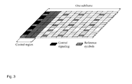
- Downlink transmissions are dynamically scheduled, i.e., in each subframe the base station transmits control information about to which terminals data is transmitted and upon which resource blocks the data is transmitted, in the current downlink subframe.
- This control signaling is typically transmitted in the first 1, 2, 3 or 4 OFDM symbols in each subframe.
- a downlink system with 3 OFDM symbols as control is illustrated in figure 3 .
- LTE uses hybrid-ARQ, where, after receiving downlink data in a subframe, the terminal attempts to decode it and reports to the base station whether the decoding was successful (ACK) or not (NAK). In case of an unsuccessful decoding attempt, the base station can retransmit the erroneous data.
- Uplink control signaling from the terminal to the base station consists of hybrid-ARQ acknowledgements for received downlink data; terminal reports related to the downlink channel conditions, used as assistance for the downlink scheduling; scheduling requests, indicating that a mobile terminal needs uplink resources for uplink data transmissions.
- the L1/L2 control information (channel-status reports, hybrid-ARQ acknowledgments, and scheduling requests) is transmitted in uplink resources (resource blocks) specifically assigned for uplink L1/L2 control on Physical Uplink Control Channel (PUCCH).
- uplink resources resource blocks
- PUCCH Physical Uplink Control Channel
- these resources are located at the edges of the total available cell bandwidth.
- Each such resource consists of twelve "subcarriers" (one resource block) within each of the two slots of an uplink subframe.
- these frequency resources are frequency hopping on the slot boundary, i.e.
- one “resource” consists of 12 subcarriers at the upper part of the spectrum within the first slot of a subframe and an equally sized resource at the lower part of the spectrum during the second slot of the subframe or vice versa. If more resources are needed for the uplink L1/L2 control signaling, e.g. in case of very large overall transmission bandwidth supporting a large number of users, additional resources blocks can be assigned next to the previously assigned resource blocks.
- the mobile terminal To transmit data in the uplink the mobile terminal has to been assigned an uplink resource for data transmission, on the Physical Uplink Shared Channel (PUSCH).
- PUSCH Physical Uplink Shared Channel
- the assignment In contrast to a data assignment in downlink, in uplink the assignment must always be consecutive in frequency, this to retain the signal carrier property of the uplink as illustrated in figure 5 .
- the middle SC(Single Carrier Frequency Division Multiple Access (FDMA))-symbol (also referred to as DFT-spread OFDM), in each slot is used to transmit a reference symbol. If the mobile terminal has been assigned an uplink resource for data transmission and at the same time instance has control information to transmit, it will transmit the control information together with the data on PUSCH.
- FDMA Single Carrier Frequency Division Multiple Access
- Uplink power control is used both on the PUSCH and on PUCCH.
- the purpose is to ensure that the mobile terminal transmits with sufficient power, but at the same time not be too high, since that would only increase the interference to other users in the network.
- a parameterized open loop combined with a closed loop mechanism is used. Roughly, the open loop part is used to set a point of operation, around which the closed loop component operates. Different parameters such as targets and partial compensation factors for user and control plane are used.
- P CMAX is the configured maximum transmit power for the mobile terminal
- M PUSCH ( i ) is the number resource blocks assigned
- PL is the estimated pathloss
- ⁇ TF ( i ) is transport format compensator
- the function f may represent either absolute or accumulative offsets.
- the closed loop power control can be operated in two different modes either accumulated or absolute. Both modes are based on a TPC (Transmit power command) which is part of the downlink control signaling.
- TPC Transmit power command
- the closed loop correction function is reset every time a new power control command is received.
- the power control command is a delta correction with regard to the previously accumulated closed loop correction.
- the base station can filter the mobile terminals power in both time and frequency to provide an accurate power control operating point for the mobile terminal.
- the accumulated power control command is reset when changing cell, entering/leaving RRC active state, an absolute TPC command is received, P O_PUCCH is received and when the mobile terminal (re)synchronizes.
- the base station has the possibility to request a power headroom report from the UE for PUSCH transmissions.
- the power headroom reports inform the base station how much transmission power the UE had left for the subframe i.
- the reported value is within the range of 40 to -23 dB, where a negative value indicates that the UE did not have enough amount of transmit power to fully conduct the transmission of data, or control information.
- P CMAX , M PUSCH ( i ), P O_PUSCH ( j ), ⁇ ( j ), PL , ⁇ TF ( i ) and f ( i ) is defined above.
- P CMAX , M PUSCH ( i ), P O_PUSCH ( j ), ⁇ ( j ), PL , ⁇ TF ( i ) and f ( i ) is defined above.
- future LTE releases it will be possible to transmit PUCCH and PUSCH at the same occasion and to transmit/receive on multiple component carriers.
- the scenario of power limitation i.e. when the UE has reached the maximum transmit power, becomes more likely.
- the base station In order for the base station to schedule PUSCH effectively, the base station needs to be aware of the available transmission power of the UE. In the prior art, the base station requests a power headroom report from the UE, which indicates how much transmission power that is used in the UE based on a PUSCH transmission in subframe i.
- the UE is requested to either report an individual power headroom report for PUCCH or a combined power headroom report for PUCCH and PUSCH according to embodiments.
- the combined power headroom report may be transmitted with the individual power headroom report for the PUSCH.
- the individual power headroom report and the combined power headroom reports may be valid for only one component carrier, e.g. for each individual component carrier, or for the sum of the component carriers.
- the base station is now able to know how much power that the PUCCH will take from the total available transmission power and correspondingly how much power which is left for the scheduled PUSCH transmission.
- a method in a UE for distributing available transmit power between PUCCH and PUSCH is determined, and at least one power headroom report indicating the available power for transmission on at least the PUCCH is transmitted to a base station.
- a method in a base station for distributing available transmit power of a UE between PUCCH and PUSCH is provided.
- at least one power headroom report indicating available power for transmission on at least the PUCCH is received from a UE and the UE is scheduled based on information of the at least one received power headroom report.
- a UE for distributing available transmit power between PUCCH and PUSCH comprises a processor configured to determine available power for transmission on at least the PUCCH, and a transmitter configured to transmit to a base station at least one power headroom report indicating the available power for transmission on at least the PUCCH.
- a base station for distributing available transmit power of a UE between PUCCH and PUSCH comprises a receiver configured to receive from the UE at least one power headroom report indicating the available power for transmission on at least the PUCCH, and a processor configured to schedule the UE based on information of the at least one received power headroom report.
- An advantage with embodiments of the present invention is that the base station can predict the available remaining transmission power when the PUSCH and PUCCH are simultaneously transmitted.
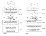
- the base station configures 601 the UE whether or not simultaneous transmission of PUCCH and PUSCH is possible as illustrated in the flowchart of figure 6 .
- the base station then signals 602 a parameter to the UE indicating whether simultaneous transmission of PUSCH and PUCCH is possible.
- the parameter may be signaled via RRC (Radio Resource Control) protocol or as part of the broadcasted system information.
- the UE receives 701 the parameter indicating whether simultaneous transmission of PUSCH and PUCCH is possible, and configures 702 the uplink transmission based on the received parameter according to an embodiment.
- a corresponding method in a base station for distributing available transmit power of a UE between PUCCH, and Physical Uplink Shared Channel, PUSCH is provided.
- the base station receives 603 from the UE at least one power headroom report indicating the available power for transmission on at least the PUCCH, and schedules 604 the UE based on information of the at least one received power headroom report.
- the power headroom reports can be created in different ways according to the embodiments which are further described below.
- P CMAX is the maximum power for the UE
- PUCCH power is the power of PUCCH.
- the existing power headroom report for PUSCH also may be available.
- PH PUCCH i P CMAX - P 0 _PUCCH + PL + h n CQI ⁇ n HARQ + ⁇ F_PUCCH F + g i
- P CMAX is the configured maximum transmit power for the mobile terminal
- PL is the estimated pathloss
- ⁇ F_PUCCH ( F ) is provided by higher layers.
- Each ⁇ F_PUCCH ( F ) value is dependent on the PUCCH format.
- h(n) is also a PUCCH format dependent value, where n CQI corresponds to the number of information bits for the channel quality information and n HARQ is the number of HARQ bits.
- g(i) is the current PUCCH power adjustment state and i is the current subframe.
- PH PUSCH_and_PUCCH i P CMAX - P 0 _PUCCH + PL + h n CQI ⁇ n HARQ + ⁇ F_PUCCH F + g i - 10 ⁇ log 10 M PUSCH i + P O_PUSCH j + ⁇ j ⁇ PL + ⁇ TF i + f i
- the power headroom can be expressed in dB in the mW or W domain.
- the power headroom report for PUSCH and PUCCH can also be used in combination with the existing power headroom report for PUSCH.
- the power headroom report indicating the available power for transmission on the PUCCH and the PUSCH is transmitted in combination with a power headroom report indicating the available power for transmission on PUSCH. In this way it is possible to determine the available power on both PUCCH and PUSCH.
- the power headroom report for PUSCH and PUCCH can also be used in combination with the power headroom report for PUCCH.
- the power headroom report indicating the available power for transmission on the PUCCH and the PUSCH is transmitted in combination with a power headroom report indicating the available power for transmission on PUCCH. In this way it is possible to determine the available power on both PUCCH and PUSCH.
- the power headroom report indicates the available transmission power for a given component carrier c.
- the power headroom report indicates the available power for transmission on the PUCCH for a given component carrier c
- PH PUCCH (c) P CMAX -PUCCH power(c) in addition to an existing power headroom report for PUSCH, e.g. defined for a specific component carrier.
- PH PUCCH i ⁇ c P CMAX - P 0 _PUCCH , c + PL c + h n CQI ⁇ n HARQ ⁇ c + ⁇ F_PUCCH F ⁇ c + g i ⁇ c where the parameters follow the definitions specified above.
- the power headroom report indicating the available power for transmission on the PUCCH and the PUSCH can be defined for a given component carrier.
- the power headroom report indicating the available power for transmission on the PUCCH and the PUSCH can transmitted in combination with a power headroom report indicating the available power for transmission on PUSCH.
- These power headroom reports can be defined for a given component carrier c. The transmission of the different reports may occur simultaneously or at separate instances.
- the power headroom report indicating the available power for transmission on the PUCCH and the PUSCH can transmitted in combination with a power headroom report indicating the available power for transmission on PUCCH.
- These power headroom reports can be defined for a given component carrier c. The transmission of the different reports may occur simultaneously or at separate instances.
- the power headroom report on a given component carrier may be triggered by a pathloss change on the same or on another component carrier.
- the UE may send a power headroom report for a carrier where the pathloss is changed beyond a certain threshold.
- a pathloss change on one component carrier may trigger a full power headroom report including reports for all component carriers.
- the power headroom reports indicating the available power for transmission on PUCCH, PUSCH and on PUCCH and PUSCH can be defined as a sum for all component carriers used by one UE.
- PUSCH may also be applied for the sounding reference signals (SRS). I.e., when simultaneous transmission of SRS and PUCCH occurs, the embodiments of the present invention are also applicable if PUSCH or PUCCH is replaced by SRS.
- SRS sounding reference signals
- the present invention is also directed to a UE (User Equipment) and a base station, also referred to as an eNB in LTE.
- the UE is configured to wirelessly communicate with a mobile telecommunication network via base stations.
- the UE and the base station comprise antennas, power amplifiers and other software means and electronic circuitry enabling the wireless communication.
- Figure 8 illustrates schematically a UE and a base station according to embodiments of the present invention.
- the UE 806 is adapted to distribute the available transmit power of a UE between PUCCH and PUSCH.
- the UE comprises a processor 804 configured to determine available power for transmission on at least the PUCCH and a transmitter 805 configured to transmit to a base station at least one power headroom report 821 indicating the available power for transmission on at least the PUCCH.
- the transmitter is configured to transmit data on PUSCH and control information on PUCCH.
- the UE comprises a receiver 803 configured to receive a parameter 825 indicating whether simultaneous transmission of PUSCH and PUCCH is possible and to e.g. receive scheduling information 820.
- the processor 804 is further configured to configure the uplink transmission based on the received parameter.
- the base station 800 is adapted to distribute the available transmit power of a UE between PUCCH and PUSCH.
- the base station comprises a receiver 807 for receiving at least one power headroom report 821 indicating the available power for transmission on at least the PUCCH and a processor 801 configured to schedule the UE based on information of the at least one received power headroom report.
- the base station comprises a transmitter 802 for transmitting scheduling information 820 regarding how to schedule future uplink transmission in the UE, wherein the scheduling information 820 is based on the headroom reports 821.
- the processor 801 may be configured to configure the UE whether or not simultaneous transmission of PUCCH and PUSCH is possible, and the transmitter 802 may be configured to signal a parameter 825 to the UE indicating whether simultaneous transmission of PUSCH and PUCCH is possible.
- the respective processor 804, 801 of the UE and the base station may be one processor or a plurality of processors configured to perform the different tasks assigned to the respective above mentioned processor of the UE and the base station.
- the available power for transmission in the different embodiment is the available remaining power that can be used for transmission on the relevant physical channel such as PUCCH and PUSCH when the power allocated for the respective channel(s) is reduced from the configured maximum transmit power for the mobile terminal.
Abstract
Description
- The present invention relates to methods and arrangements in a mobile telecommunication network, and in particular to report transmit power headroom in conjunction with simultaneous transmission of physical uplink shared channels and physical uplink control channels.
- 3GPP Long Term Evolution (LTE) is a project within the 3rd Generation Partnership Project (3GPP) to improve the UMTS standard with e.g. increased capacity and higher data rates towards the fourth generation of mobile telecommunication networks. Hence, the LTE specifications provide downlink peak rates up to 300 Mbps, an uplink of up to 75 Mbit/s and radio access network round-trip times of less than 10 ms. In addition, LTE supports scalable carrier bandwidths from 20 MHz down to 1.4 MHz and supports both FDD (Frequency Division Duplex) and TDD (Time Division Duplex).
- LTE uses OFDM (Orthogonal Frequency Division Multiplex) in the downlink and DFT (Discrete Fourier Transform)-spread OFDM in the uplink. The basic LTE downlink physical resource can thus be seen as a time-frequency grid as illustrated in
figure 1 , where each resource element corresponds to one OFDM subcarrier during one OFDM symbol interval. - In the time domain, LTE downlink transmissions are organized into radio frames of 10 ms, each radio frame consisting of ten equally-sized subframes of length Tsubframe = 1 ms as illustrated in
figure 2 . - Furthermore, the resource allocation in LTE is typically described in terms of resource blocks, where a resource block corresponds to one slot (0.5 ms) in the time domain and 12 contiguous subcarriers in the frequency domain. Resource blocks are numbered in the frequency domain, starting with 0 from one end of the system bandwidth.
- Downlink transmissions are dynamically scheduled, i.e., in each subframe the base station transmits control information about to which terminals data is transmitted and upon which resource blocks the data is transmitted, in the current downlink subframe. This control signaling is typically transmitted in the first 1, 2, 3 or 4 OFDM symbols in each subframe. A downlink system with 3 OFDM symbols as control is illustrated in
figure 3 . - LTE uses hybrid-ARQ, where, after receiving downlink data in a subframe, the terminal attempts to decode it and reports to the base station whether the decoding was successful (ACK) or not (NAK). In case of an unsuccessful decoding attempt, the base station can retransmit the erroneous data.
- Uplink control signaling from the terminal to the base station consists of hybrid-ARQ acknowledgements for received downlink data; terminal reports related to the downlink channel conditions, used as assistance for the downlink scheduling; scheduling requests, indicating that a mobile terminal needs uplink resources for uplink data transmissions.
- If the mobile terminal has not been assigned an uplink resource for data transmission, the L1/L2 control information (channel-status reports, hybrid-ARQ acknowledgments, and scheduling requests) is transmitted in uplink resources (resource blocks) specifically assigned for uplink L1/L2 control on Physical Uplink Control Channel (PUCCH). As illustrated in
figure 4 , these resources are located at the edges of the total available cell bandwidth. Each such resource consists of twelve "subcarriers" (one resource block) within each of the two slots of an uplink subframe. In order to provide frequency diversity, these frequency resources are frequency hopping on the slot boundary, i.e. one "resource" consists of 12 subcarriers at the upper part of the spectrum within the first slot of a subframe and an equally sized resource at the lower part of the spectrum during the second slot of the subframe or vice versa. If more resources are needed for the uplink L1/L2 control signaling, e.g. in case of very large overall transmission bandwidth supporting a large number of users, additional resources blocks can be assigned next to the previously assigned resource blocks. - To transmit data in the uplink the mobile terminal has to been assigned an uplink resource for data transmission, on the Physical Uplink Shared Channel (PUSCH). In contrast to a data assignment in downlink, in uplink the assignment must always be consecutive in frequency, this to retain the signal carrier property of the uplink as illustrated in
figure 5 . - The middle SC(Single Carrier Frequency Division Multiple Access (FDMA))-symbol (also referred to as DFT-spread OFDM), in each slot is used to transmit a reference symbol. If the mobile terminal has been assigned an uplink resource for data transmission and at the same time instance has control information to transmit, it will transmit the control information together with the data on PUSCH.
- Uplink power control is used both on the PUSCH and on PUCCH. The purpose is to ensure that the mobile terminal transmits with sufficient power, but at the same time not be too high, since that would only increase the interference to other users in the network. In both cases, a parameterized open loop combined with a closed loop mechanism is used. Roughly, the open loop part is used to set a point of operation, around which the closed loop component operates. Different parameters such as targets and partial compensation factors for user and control plane are used.
- In more detail, for PUSCH the mobile terminal sets the output power according to

where P CMAX is the configured maximum transmit power for the mobile terminal, M PUSCH(i) is the number resource blocks assigned, P O_PUSCH(j) and α control the target received power, PL is the estimated pathloss, ΔTF(i) is transport format compensator and f(i) is the a UE (User Equipment) specific offset or 'closed loop correction'. The function f may represent either absolute or accumulative offsets. The closed loop power control can be operated in two different modes either accumulated or absolute. Both modes are based on a TPC (Transmit power command) which is part of the downlink control signaling. When absolute power control is used, the closed loop correction function is reset every time a new power control command is received. When accumulated power control is used, the power control command is a delta correction with regard to the previously accumulated closed loop correction. The base station can filter the mobile terminals power in both time and frequency to provide an accurate power control operating point for the mobile terminal. The accumulated power control command is defined as f(i)= f(i-1)+δPUSCH (i-KPUSCH ), where δPUSCH is the TPC command received in KPUSCH subframe before the current subframe i and f(i-1) is the accumulated power control value. - The accumulated power control command is reset when changing cell, entering/leaving RRC active state, an absolute TPC command is received, P O_PUCCH is received and when the mobile terminal (re)synchronizes.
- In the case of reset the power control command is reset to f(0)=ΔPrampup +δ msg2, where δ msg2 is the TPC command indicated in the random access response and ΔPrampup corresponds to the total power ramp-up form the first to the last random access preamble.
- The PUCCH power control has in principle the same configurable parameters with the exception that PUCCH only has full pathloss compensation, i.e. does only cover the case of α = 1.
- In existing LTE systems, the base station has the possibility to request a power headroom report from the UE for PUSCH transmissions. The power headroom reports inform the base station how much transmission power the UE had left for the subframe i. The reported value is within the range of 40 to -23 dB, where a negative value indicates that the UE did not have enough amount of transmit power to fully conduct the transmission of data, or control information.
- The UE PUSCH power headroom PH for subframe i is defined as

where P CMAX, M PUSCH(i), P O_PUSCH(j), α(j), PL, ΔTF(i) and f(i) is defined above. In future LTE releases it will be possible to transmit PUCCH and PUSCH at the same occasion and to transmit/receive on multiple component carriers. With the added possibility for the UE to transmit PUSCH and PUCCH at the same occasion, the scenario of power limitation, i.e. when the UE has reached the maximum transmit power, becomes more likely. - In order for the base station to schedule PUSCH effectively, the base station needs to be aware of the available transmission power of the UE. In the prior art, the base station requests a power headroom report from the UE, which indicates how much transmission power that is used in the UE based on a PUSCH transmission in subframe i.
- Future LTE releases, will give the possibility for the UE to transmit PUSCH (Physical uplink shared channel) and PUCCH (Physical uplink control channel) simultaneously. As both the PUCCH and the PUSCH can be transmitted simultaneously the transmit power in the UE needs to be shared among the two channels.
- It is therefore desired to be able to achieve an improved solution for predicting the available transmission power.
- This is achieved by taking account of the PUCCH transmission power in a power headroom report. Hence, the UE is requested to either report an individual power headroom report for PUCCH or a combined power headroom report for PUCCH and PUSCH according to embodiments. For example the combined power headroom report may be transmitted with the individual power headroom report for the PUSCH. The individual power headroom report and the combined power headroom reports may be valid for only one component carrier, e.g. for each individual component carrier, or for the sum of the component carriers.
- By using the embodiments of the present invention, the base station is now able to know how much power that the PUCCH will take from the total available transmission power and correspondingly how much power which is left for the scheduled PUSCH transmission.
- According to a first aspect of embodiments of the present invention a method in a UE for distributing available transmit power between PUCCH and PUSCH. In the method, available power for transmission on at least the PUCCH is determined, and at least one power headroom report indicating the available power for transmission on at least the PUCCH is transmitted to a base station.
- According to a second aspect of embodiments of the present invention a method in a base station for distributing available transmit power of a UE between PUCCH and PUSCH is provided. In the method, at least one power headroom report indicating available power for transmission on at least the PUCCH is received from a UE and the UE is scheduled based on information of the at least one received power headroom report.
- According to a third aspect of embodiments of the present invention a UE for distributing available transmit power between PUCCH and PUSCH is provided. The UE comprises a processor configured to determine available power for transmission on at least the PUCCH, and a transmitter configured to transmit to a base station at least one power headroom report indicating the available power for transmission on at least the PUCCH.
- A base station for distributing available transmit power of a UE between PUCCH and PUSCH is provided. The base station comprises a receiver configured to receive from the UE at least one power headroom report indicating the available power for transmission on at least the PUCCH, and a processor configured to schedule the UE based on information of the at least one received power headroom report.
- An advantage with embodiments of the present invention is that the base station can predict the available remaining transmission power when the PUSCH and PUCCH are simultaneously transmitted.
-
-
Figure 1 illustrates the LTE downlink physical resources according to prior art. -
Figure 2 illustrates the LTE time-domain structure according to prior art. -
Figure 3 illustrates the downlink subframes according to prior art. -
Figure 4 illustrates uplink L1/L2 control signaling transmission on PUCCH according to prior art. -
Figure 5 illustrates the PUSCH resource assignment according to prior art. -
Figures 6 and 7 are flowcharts of the methods according to embodiments of the present invention. -
Figure 8 illustrates the UE and the base station according to embodiments of the present invention. - Although the embodiments of the present invention will be described in the context of an LTE network, the embodiments can also be implemented in other networks enabling simultaneous transmission of different physical channels.
- In accordance with embodiments, the base station configures 601 the UE whether or not simultaneous transmission of PUCCH and PUSCH is possible as illustrated in the flowchart of
figure 6 . The base station then signals 602 a parameter to the UE indicating whether simultaneous transmission of PUSCH and PUCCH is possible. The parameter may be signaled via RRC (Radio Resource Control) protocol or as part of the broadcasted system information. Hence, as illustrated in the flowchart offigure 7 , the UE receives 701 the parameter indicating whether simultaneous transmission of PUSCH and PUCCH is possible, and configures 702 the uplink transmission based on the received parameter according to an embodiment. - As a UE has a limited available transmit power, it would be desired to schedule the UE such that the available transmission power can be taken into account. Hence in situations when simultaneous transmission of PUCCH and PUSCH is possible, it would be desired to be able to take the PUSCH and the PUCCH transmission into account when determining the available UE transmit power.
- This is achieved according to embodiments of the present invention by introducing power headroom reports indicating the available power for transmission on at least the PUCCH. This implies that a method in a UE for distributing the available transmit power to avoid violation of UE power limitations on the PUCCH and the PUSCH is provided. The method is illustrated in the flowchart of
figure 7 which shows that the method comprises determining 703 available power for transmission on at least the PUCCH, and transmitting 704 to a base station at least one power headroom report indicating the available power for transmission on at least the PUCCH. - Accordingly, a corresponding method in a base station for distributing available transmit power of a UE between PUCCH, and Physical Uplink Shared Channel, PUSCH is provided. The base station receives 603 from the UE at least one power headroom report indicating the available power for transmission on at least the PUCCH, and schedules 604 the UE based on information of the at least one received power headroom report.
- The power headroom reports can be created in different ways according to the embodiments which are further described below.
- In a first embodiment the power headroom report indicates the available power for transmission on the PUCCH, i.e. PHPUCCH = PCMAX - PUCCH power where PCMAX is the maximum power for the UE and PUCCH power is the power of PUCCH. It should be noted that the existing power headroom report for PUSCH (PHPUSCH) also may be available. An example how the power headroom report for PUCCH (PHPUCCH), among many possible implementations, can be determined, is shown below:

where P CMAX is the configured maximum transmit power for the mobile terminal, P O_PUSCH(j), PL is the estimated pathloss, ΔF_PUCCH(F) is provided by higher layers. Each ΔF_PUCCH(F) value is dependent on the PUCCH format. h(n) is also a PUCCH format dependent value, where nCQI corresponds to the number of information bits for the channel quality information and nHARQ is the number of HARQ bits. g(i) is the current PUCCH power adjustment state and i is the current subframe. - In a second alternative embodiment the existing power headroom report for PUSCH is extended to also include PUCCH which is implies that the power headroom is reported for both PUSCH and PUCCH in the same report referred to as PHPUCCH+PUSCH, where PHPUCCH+PUSCH=Pcmax-(the PUSCH power + the PUCCH power). An example among many possible implementations is shown below:

where the parameter definitions are specified above. It should also be noted that the power headroom can be expressed in dB in the mW or W domain. For the power headroom report indicating the available power for transmission on PUSCH and PUCCH, the power headroom report can be defined as:
- It should be noted that all PH reports can be defined in the mW or W domain and expressed in dB in this way.
- According to a third embodiment, the power headroom report for PUSCH and PUCCH can also be used in combination with the existing power headroom report for PUSCH. Thus, the power headroom report indicating the available power for transmission on the PUCCH and the PUSCH is transmitted in combination with a power headroom report indicating the available power for transmission on PUSCH. In this way it is possible to determine the available power on both PUCCH and PUSCH.
- According to a fourth embodiment, the power headroom report for PUSCH and PUCCH can also be used in combination with the power headroom report for PUCCH. Thus, the power headroom report indicating the available power for transmission on the PUCCH and the PUSCH is transmitted in combination with a power headroom report indicating the available power for transmission on PUCCH. In this way it is possible to determine the available power on both PUCCH and PUSCH.
- According to further embodiments, the power headroom report indicates the available transmission power for a given component carrier c. In the example below the power headroom report indicates the available power for transmission on the PUCCH for a given component carrier c, PHPUCCH(c)=PCMAX-PUCCH power(c) in addition to an existing power headroom report for PUSCH, e.g. defined for a specific component carrier. An example among many possible implementations is shown below:

where the parameters follow the definitions specified above. - In a further example, the power headroom report indicating the available power for transmission on the PUCCH and the PUSCH can be defined for a given component carrier. I.e. PHPUCCH+PUSCH (c)=Pcmax-(PUSCH power(c)+PUCCH power(c)) can be exemplified as:

where the parameters follow the definitions specified above. - In a yet further example, the power headroom report indicating the available power for transmission on the PUCCH and the PUSCH can transmitted in combination with a power headroom report indicating the available power for transmission on PUSCH. These power headroom reports can be defined for a given component carrier c. The transmission of the different reports may occur simultaneously or at separate instances.
- In a yet further example, the power headroom report indicating the available power for transmission on the PUCCH and the PUSCH can transmitted in combination with a power headroom report indicating the available power for transmission on PUCCH. These power headroom reports can be defined for a given component carrier c. The transmission of the different reports may occur simultaneously or at separate instances.
- The power headroom report on a given component carrier may be triggered by a pathloss change on the same or on another component carrier. The UE may send a power headroom report for a carrier where the pathloss is changed beyond a certain threshold. Alternatively, a pathloss change on one component carrier may trigger a full power headroom report including reports for all component carriers.
- The power headroom reports indicating the available power for transmission on PUCCH, PUSCH and on PUCCH and PUSCH can be defined as a sum for all component carriers used by one UE.
- It should be noted that the principles described for PUSCH may also be applied for the sounding reference signals (SRS). I.e., when simultaneous transmission of SRS and PUCCH occurs, the embodiments of the present invention are also applicable if PUSCH or PUCCH is replaced by SRS.
- The present invention is also directed to a UE (User Equipment) and a base station, also referred to as an eNB in LTE. The UE is configured to wirelessly communicate with a mobile telecommunication network via base stations. Hence, the UE and the base station comprise antennas, power amplifiers and other software means and electronic circuitry enabling the wireless communication.
Figure 8 illustrates schematically a UE and a base station according to embodiments of the present invention. - Accordingly, the
UE 806 is adapted to distribute the available transmit power of a UE between PUCCH and PUSCH. The UE comprises aprocessor 804 configured to determine available power for transmission on at least the PUCCH and atransmitter 805 configured to transmit to a base station at least onepower headroom report 821 indicating the available power for transmission on at least the PUCCH. As indicated infigure 8 , the transmitter is configured to transmit data on PUSCH and control information on PUCCH. Further, the UE comprises areceiver 803 configured to receive aparameter 825 indicating whether simultaneous transmission of PUSCH and PUCCH is possible and to e.g. receivescheduling information 820. Theprocessor 804 is further configured to configure the uplink transmission based on the received parameter. - Hence, the
base station 800 is adapted to distribute the available transmit power of a UE between PUCCH and PUSCH. The base station comprises areceiver 807 for receiving at least onepower headroom report 821 indicating the available power for transmission on at least the PUCCH and aprocessor 801 configured to schedule the UE based on information of the at least one received power headroom report. Furthermore, the base station comprises atransmitter 802 for transmittingscheduling information 820 regarding how to schedule future uplink transmission in the UE, wherein thescheduling information 820 is based on the headroom reports 821. - In addition the
processor 801 may be configured to configure the UE whether or not simultaneous transmission of PUCCH and PUSCH is possible, and thetransmitter 802 may be configured to signal aparameter 825 to the UE indicating whether simultaneous transmission of PUSCH and PUCCH is possible. - It should be noted that the
respective processor - It should also be noted that the available power for transmission in the different embodiment is the available remaining power that can be used for transmission on the relevant physical channel such as PUCCH and PUSCH when the power allocated for the respective channel(s) is reduced from the configured maximum transmit power for the mobile terminal.
- Modifications and other embodiments of the disclosed invention will come to mind to one skilled in the art having the benefit of the teachings presented in the foregoing descriptions and the associated drawings. Therefore, it is to be understood that the invention is not to be limited to the specific embodiments disclosed and that modifications and other embodiments are intended to be included within the scope of this disclosure. Although specific terms may be employed herein, they are used in a generic and descriptive sense only and not for purposes of limitation.
Claims (18)
- A method in a User Equipment, UE, for distributing available transmit power between Physical Uplink Control Channel, PUCCH, and Physical Uplink Shared Channel, PUSCH , the method comprises:- determining (703) available power for transmission on at least the PUCCH, and- transmitting (704) to a base station at least one power headroom report indicating the available power for transmission on at least the PUCCH.
- The method according to claim 1, wherein the available power is determined for transmission on the PUCCH and the PUSCH and the at least one power headroom report indicates the available power for transmission on the PUCCH and the PUSCH.
- The method according to claim 2, wherein the at least one power headroom report indicating the available power for transmission on the PUCCH and the PUSCH is transmitted in combination with a power headroom report indicating the available power for transmission on PUSCH.
- The method according to claim 2, wherein the at least one power headroom report indicating the available power for transmission on the PUCCH and the PUSCH is transmitted in combination with a power headroom report indicating the available power for transmission on PUCCH.
- The method according to claim 1, wherein the available power is determined for transmission on the PUCCH and the at least one power headroom report indicates the available power for transmission on the PUCCH.
- The method according to any of claims 1-5, wherein the at least one power headroom report is valid for a given component carrier c.
- The method according to any of claims 1-5, wherein the at least one power headroom report is defined as a sum for all component carriers.
- The method according to claim 4, wherein the at least one power headroom report indicating the available power for transmission on the PUCCH and the PUSCH is transmitted simultaneously with the power headroom report indicating the available power for transmission on PUSCH.
- The method according to claim 4, wherein the at least one power headroom report indicating the available power for transmission on the PUCCH and the PUSCH is transmitted at a separate instance compared with the power headroom report indicating the available power for transmission on PUSCH.
- The method according to any of claims 1-9, further comprising :- receiving (701) a parameter indicating whether simultaneous transmission of PUSCH and PUCCH is possible, and- configuring (702) the uplink transmission based on the received parameter.
- A method in a base station for distributing available transmit power of a User Equipment, UE, between Physical Uplink Control Channel, PUCCH, and Physical Uplink Shared Channel, PUSCH , the method comprises:- receiving (603) from the UE at least one power headroom report indicating available power for transmission on at least the PUCCH, and- scheduling (604) the UE based on information of the at least one received power headroom report.
- The method according to claim 11, wherein the at least one power headroom report indicates the available power for transmission on the PUCCH and the PUSCH.
- The method according to claim 12, wherein the at least one power headroom report indicating the available power for transmission on the PUCCH and the PUSCH is received in combination with a power headroom report indicating the available power for transmission on PUSCH.
- The method according to claim 12, wherein the at least one power headroom report indicating the available power for transmission on the PUCCH and the PUSCH is received in combination with a power headroom report indicating the available power for transmission on PUCCH.
- The method according to claim 11, wherein the at least one power headroom report indicates the available power for transmission on the PUCCH.
- The method according to any of claims 11-15, further comprises:- configuring (601) the UE whether or not simultaneous transmission of Physical Uplink Control Channel, PUCCH, and Physical Uplink Shared Channel, PUSCH is possible, and- signalling (602) a parameter to the UE indicating whether simultaneous transmission of PUSCH and PUCCH is possible.
- A User Equipment, UE, (806) for distributing available transmit between Physical Uplink Control Channel, PUCCH, and Physical Uplink Shared Channel, PUSCH, the UE (806) comprises a processor (804) configured to determine available power for transmission on at least the PUCCH, and a transmitter (805) configured to transmit to a base station at least one power headroom report indicating the available power for transmission on at least the PUCCH.
- A base station (800) for distributing available transmit power of a User Equipment, UE, (806) between Physical Uplink Control Channel, PUCCH, and Physical Uplink Shared Channel, PUSCH, the base station comprises a receiver (807) configured to receive from the UE at least one power headroom report indicating the available power for transmission on at least the PUCCH, and a processor (801) configured to schedule the UE based on information of the at least one received power headroom report.
Priority Applications (2)
| Application Number | Priority Date | Filing Date | Title |
|---|---|---|---|
| EP19193587.3A EP3624509A1 (en) | 2009-10-02 | 2010-09-29 | Methods and arrangements for power headroom reporting in a mobile telecommunications network |
| PL14197192T PL2849505T3 (en) | 2009-10-02 | 2010-09-29 | Methods and arrangements for power headroom reporting in a mobile telecommunications network |
Applications Claiming Priority (3)
| Application Number | Priority Date | Filing Date | Title |
|---|---|---|---|
| US24809209P | 2009-10-02 | 2009-10-02 | |
| PCT/EP2010/064405 WO2011039214A2 (en) | 2009-10-02 | 2010-09-29 | Methods and arrangements in a mobile telecommunications network |
| EP10759642.1A EP2484162B1 (en) | 2009-10-02 | 2010-09-29 | Methods and arrangements in a mobile telecommunications network |
Related Parent Applications (2)
| Application Number | Title | Priority Date | Filing Date |
|---|---|---|---|
| EP10759642.1A Division-Into EP2484162B1 (en) | 2009-10-02 | 2010-09-29 | Methods and arrangements in a mobile telecommunications network |
| EP10759642.1A Division EP2484162B1 (en) | 2009-10-02 | 2010-09-29 | Methods and arrangements in a mobile telecommunications network |
Related Child Applications (1)
| Application Number | Title | Priority Date | Filing Date |
|---|---|---|---|
| EP19193587.3A Division EP3624509A1 (en) | 2009-10-02 | 2010-09-29 | Methods and arrangements for power headroom reporting in a mobile telecommunications network |
Publications (2)
| Publication Number | Publication Date |
|---|---|
| EP2849505A1 true EP2849505A1 (en) | 2015-03-18 |
| EP2849505B1 EP2849505B1 (en) | 2019-08-28 |
Family
ID=43805745
Family Applications (3)
| Application Number | Title | Priority Date | Filing Date |
|---|---|---|---|
| EP19193587.3A Pending EP3624509A1 (en) | 2009-10-02 | 2010-09-29 | Methods and arrangements for power headroom reporting in a mobile telecommunications network |
| EP14197192.9A Active EP2849505B1 (en) | 2009-10-02 | 2010-09-29 | Methods and arrangements for power headroom reporting in a mobile telecommunications network |
| EP10759642.1A Active EP2484162B1 (en) | 2009-10-02 | 2010-09-29 | Methods and arrangements in a mobile telecommunications network |
Family Applications Before (1)
| Application Number | Title | Priority Date | Filing Date |
|---|---|---|---|
| EP19193587.3A Pending EP3624509A1 (en) | 2009-10-02 | 2010-09-29 | Methods and arrangements for power headroom reporting in a mobile telecommunications network |
Family Applications After (1)
| Application Number | Title | Priority Date | Filing Date |
|---|---|---|---|
| EP10759642.1A Active EP2484162B1 (en) | 2009-10-02 | 2010-09-29 | Methods and arrangements in a mobile telecommunications network |
Country Status (23)
| Country | Link |
|---|---|
| US (1) | US20110080838A1 (en) |
| EP (3) | EP3624509A1 (en) |
| JP (3) | JP5678070B2 (en) |
| KR (1) | KR101785124B1 (en) |
| CN (2) | CN105338610B (en) |
| AU (1) | AU2010303058B2 (en) |
| BR (1) | BR112012007385B1 (en) |
| CA (1) | CA2776348C (en) |
| DK (1) | DK2849505T3 (en) |
| ES (2) | ES2755892T3 (en) |
| HK (2) | HK1173023A1 (en) |
| IL (1) | IL218699A (en) |
| IN (1) | IN2012DN02169A (en) |
| MA (1) | MA33698B1 (en) |
| MX (1) | MX2012003447A (en) |
| MY (1) | MY163280A (en) |
| NZ (1) | NZ599092A (en) |
| PL (1) | PL2849505T3 (en) |
| PT (1) | PT2849505T (en) |
| RU (1) | RU2517366C2 (en) |
| SG (1) | SG179028A1 (en) |
| WO (1) | WO2011039214A2 (en) |
| ZA (1) | ZA201201801B (en) |
Cited By (1)
| Publication number | Priority date | Publication date | Assignee | Title |
|---|---|---|---|---|
| WO2018139860A1 (en) * | 2017-01-24 | 2018-08-02 | Samsung Electronics Co., Ltd. | Method and device for reporting a power headroom report |
Families Citing this family (24)
| Publication number | Priority date | Publication date | Assignee | Title |
|---|---|---|---|---|
| KR101230392B1 (en) * | 2008-03-20 | 2013-02-08 | 인터디지탈 패튼 홀딩스, 인크 | Method and apparatus for selecting enhanced dedicated channel transport format combination in cell_fach state and idle mode |
| US8743786B2 (en) * | 2009-03-17 | 2014-06-03 | Unwired Planet, Llc | Power backoff for multi-carrier uplink transmissions |
| KR101734948B1 (en) * | 2009-10-09 | 2017-05-12 | 삼성전자주식회사 | Method of Power Headroom Report, Resource Allocation and Power Control |
| EP2317815A1 (en) | 2009-11-02 | 2011-05-04 | Panasonic Corporation | Power-limit reporting in a communication system using carrier aggregation |
| US8537767B2 (en) * | 2010-04-06 | 2013-09-17 | Sunplus Technology Co., Ltd | Method for performing power headroom reporting procedure and PHR MAC control element |
| KR101831281B1 (en) | 2010-04-06 | 2018-02-23 | 삼성전자주식회사 | Device and method for handling scheduling information in wireless communication system |
| US20120113908A1 (en) * | 2010-05-06 | 2012-05-10 | Yu-Chih Jen | Method of Enhancing Uplink Transmission and Related Communication Device |
| US8891446B2 (en) * | 2010-05-10 | 2014-11-18 | Qualcomm Incorporated | Power control with cross-subframe assignment |
| US8638868B2 (en) | 2010-06-23 | 2014-01-28 | Telefonaktiebolaget L M Ericsson (Publ) | Methods and apparatus for varying reduced transmission resources |
| WO2012002684A2 (en) * | 2010-06-28 | 2012-01-05 | Samsung Electronics Co., Ltd. | Method and apparatus for reporting maximum transmission power in wireless communication |
| KR101740366B1 (en) * | 2010-06-28 | 2017-05-29 | 삼성전자주식회사 | Apparatus and method for reporting uplink maximum transmission power in wireless communication system |
| US8954106B2 (en) * | 2010-08-10 | 2015-02-10 | Samsung Electronics Co., Ltd. | Method and apparatus for configuring power headroom information in mobile communication system supporting carrier aggregation |
| KR20120018041A (en) * | 2010-08-20 | 2012-02-29 | 주식회사 팬택 | Apparatus and method for transmitting information on power headroom in multiple component carrier system |
| US8687727B2 (en) * | 2010-11-05 | 2014-04-01 | Intel Corporation | Coordinated multi-point transmission using interference feedback |
| KR20120121787A (en) * | 2011-04-27 | 2012-11-06 | 주식회사 팬택 | Apparatus And Method For Controling Transmission Power Of Reference SignalIn a Communication System |
| US9185666B2 (en) * | 2011-05-06 | 2015-11-10 | Qualcomm Incorporated | Power headroom reporting related to power management maximum power reduction |
| JP6073073B2 (en) | 2012-05-10 | 2017-02-01 | シャープ株式会社 | Terminal apparatus, base station apparatus, and communication method |
| WO2015020440A1 (en) * | 2013-08-06 | 2015-02-12 | Lg Electronics Inc. | The method and apparatus for wireless communication |
| WO2015069013A1 (en) * | 2013-11-08 | 2015-05-14 | 주식회사 케이티 | Method for controlling uplink transmission power and apparatus thereof |
| US10834687B2 (en) * | 2016-11-21 | 2020-11-10 | Qualcomm Incorporated | Power headroom reporting for systems with multiple transmission time intervals |
| CN109392072B (en) * | 2017-08-14 | 2021-08-03 | 普天信息技术有限公司 | Power headroom calculation method |
| CN108199744A (en) * | 2018-02-09 | 2018-06-22 | 北京佰才邦技术有限公司 | Messaging parameter indicating means, base station, communication means and user equipment |
| US10681644B2 (en) * | 2018-08-21 | 2020-06-09 | Qualcomm Incorporated | Reporting actual uplink transmission power |
| US20220104137A1 (en) * | 2019-01-11 | 2022-03-31 | Telefonaktiebolaget Lm Ericsson (Publ) | Power Control Reporting in a Wireless Communication System |
Citations (1)
| Publication number | Priority date | Publication date | Assignee | Title |
|---|---|---|---|---|
| WO2010091425A2 (en) * | 2009-02-09 | 2010-08-12 | Interdigital Patent Holdings, Inc. | Apparatus and method for uplink power control for a wireless transmitter/receiver unit utilizing multiple carriers |
Family Cites Families (31)
| Publication number | Priority date | Publication date | Assignee | Title |
|---|---|---|---|---|
| KR980007105A (en) * | 1996-06-28 | 1998-03-30 | 김광호 | Method for controlling transmission power of mobile station |
| US6426960B2 (en) * | 1997-06-24 | 2002-07-30 | Qualcomm Incorporated | Increased capacity data transmission in a CDMA wireless communication system |
| US9078225B2 (en) * | 2003-06-16 | 2015-07-07 | Telefonaktiebolaget L M Ericsson (Publ) | Dynamic mobile power headroom threshold for determining rate increases in the reverse traffic channel of a CDMA network |
| US7408895B2 (en) * | 2005-04-20 | 2008-08-05 | Interdigital Technology Corporation | Method and apparatus for scheduling transmissions via an enhanced dedicated channel |
| RU2386213C2 (en) * | 2005-09-22 | 2010-04-10 | Мицубиси Денки Кабусики Кайся | Communication method |
| US7996032B2 (en) * | 2006-03-27 | 2011-08-09 | Qualcomm Incorporated | Power control and resource management in orthogonal wireless systems |
| BRPI0807885A2 (en) * | 2007-03-01 | 2014-06-17 | Ntt Docomo Inc | BASE STATION APPARATUS AND COMMUNICATION CONTROL METHOD. |
| JP4555890B2 (en) * | 2007-03-19 | 2010-10-06 | 株式会社エヌ・ティ・ティ・ドコモ | User equipment in mobile communication system |
| AU2008265071B2 (en) * | 2007-06-20 | 2013-03-28 | Cellular Communications Equipment Llc | Power headroom reporting method |
| CN101340622B (en) * | 2007-07-06 | 2012-01-11 | 中兴通讯股份有限公司 | Distribution method of multi-carrier reinforced uplink power resource |
| CN101340711B (en) * | 2007-07-06 | 2012-05-23 | 中兴通讯股份有限公司 | Scheduling information uploading method for multi-carrier reinforced uplink access system |
| JPWO2009022599A1 (en) * | 2007-08-14 | 2010-11-11 | 株式会社エヌ・ティ・ティ・ドコモ | Receiving apparatus and data acquisition method |
| US20090088195A1 (en) * | 2007-09-28 | 2009-04-02 | Nokia Corporation | Method and apparatus for signaling of scheduling information |
| US9084205B2 (en) * | 2007-11-09 | 2015-07-14 | Rpx Clearinghouse Llc | Uplink power control scheme for a wireless communication system |
| US20090175187A1 (en) * | 2008-01-07 | 2009-07-09 | Kristina Jersenius | Method and Arrangement for Triggering Power Headroom Report Transmissions in a Telecommunications System |
| US8233458B2 (en) * | 2008-01-07 | 2012-07-31 | Lg Electronics Inc. | Method of controlling transmission power in a wireless communication system |
| ES2798599T3 (en) * | 2008-03-26 | 2020-12-11 | Vivo Mobile Communication Co Ltd | Power margin reporting reporting extension |
| US20110194514A1 (en) * | 2008-07-30 | 2011-08-11 | Moon Il Lee | Method and apparatus of receiving data in wireless communication system |
| WO2010018226A2 (en) * | 2008-08-15 | 2010-02-18 | Nokia Siemens Networks Oy | Backward compatible physical uplink control channel resource mapping |
| JP4636153B2 (en) * | 2008-09-26 | 2011-02-23 | ブラザー工業株式会社 | Image processing apparatus and network system |
| MX2011010305A (en) * | 2009-03-30 | 2011-12-16 | Research In Motion Ltd | User equipment component carrier allocation. |
| CN201780605U (en) * | 2009-04-22 | 2011-03-30 | 万信电子科技有限公司 | Clothes fitting system |
| US20100272091A1 (en) * | 2009-04-27 | 2010-10-28 | Motorola, Inc. | Uplink Scheduling Supoort in Multi-Carrier Wireless Communication Systems |
| US8437798B2 (en) * | 2009-04-27 | 2013-05-07 | Motorola Mobility Llc | Uplink scheduling support in multi-carrier wireless communication systems |
| US8724572B2 (en) * | 2009-04-28 | 2014-05-13 | Nokia Corporation | Channel state information feedback |
| EP2425666A1 (en) * | 2009-04-30 | 2012-03-07 | Telefonaktiebolaget LM Ericsson (publ) | Method and arrangement in a wireless communications system |
| CA2763448C (en) * | 2009-05-22 | 2016-09-06 | Research In Motion Limited | Power headroom reporting for carrier aggregation |
| EP3687253B1 (en) * | 2009-06-26 | 2021-04-07 | Sun Patent Trust | Radio communication apparatuses and radio communication method |
| US9288808B2 (en) * | 2009-08-14 | 2016-03-15 | Blackberry Limited | Method and apparatus for power sharing carrier set for carrier aggregation |
| AU2010300447A1 (en) * | 2009-10-01 | 2012-04-26 | Interdigital Patent Holdings, Inc. | Power control methods and apparatus |
| CN103168441B (en) * | 2010-06-18 | 2016-04-13 | 黑莓有限公司 | For the system and method for the uplink control information transmission in carrier aggregation |
-
2010
- 2010-09-28 US US12/892,240 patent/US20110080838A1/en not_active Abandoned
- 2010-09-29 MX MX2012003447A patent/MX2012003447A/en active IP Right Grant
- 2010-09-29 DK DK14197192T patent/DK2849505T3/en active
- 2010-09-29 RU RU2012117825/07A patent/RU2517366C2/en active
- 2010-09-29 EP EP19193587.3A patent/EP3624509A1/en active Pending
- 2010-09-29 KR KR1020127010724A patent/KR101785124B1/en active IP Right Grant
- 2010-09-29 EP EP14197192.9A patent/EP2849505B1/en active Active
- 2010-09-29 EP EP10759642.1A patent/EP2484162B1/en active Active
- 2010-09-29 CN CN201510804835.7A patent/CN105338610B/en active Active
- 2010-09-29 AU AU2010303058A patent/AU2010303058B2/en active Active
- 2010-09-29 MY MYPI2012001065A patent/MY163280A/en unknown
- 2010-09-29 PT PT141971929T patent/PT2849505T/en unknown
- 2010-09-29 SG SG2012016051A patent/SG179028A1/en unknown
- 2010-09-29 IN IN2169DEN2012 patent/IN2012DN02169A/en unknown
- 2010-09-29 CA CA2776348A patent/CA2776348C/en active Active
- 2010-09-29 NZ NZ599092A patent/NZ599092A/en unknown
- 2010-09-29 JP JP2012531382A patent/JP5678070B2/en active Active
- 2010-09-29 CN CN201080045137.9A patent/CN102577543B/en active Active
- 2010-09-29 ES ES14197192T patent/ES2755892T3/en active Active
- 2010-09-29 ES ES10759642.1T patent/ES2535332T3/en active Active
- 2010-09-29 WO PCT/EP2010/064405 patent/WO2011039214A2/en active Application Filing
- 2010-09-29 BR BR112012007385-0A patent/BR112012007385B1/en active IP Right Grant
- 2010-09-29 PL PL14197192T patent/PL2849505T3/en unknown
-
2012
- 2012-03-12 ZA ZA2012/01801A patent/ZA201201801B/en unknown
- 2012-03-18 IL IL218699A patent/IL218699A/en active IP Right Grant
- 2012-04-26 MA MA34812A patent/MA33698B1/en unknown
-
2013
- 2013-01-02 HK HK13100029.0A patent/HK1173023A1/en unknown
-
2015
- 2015-01-05 JP JP2015000494A patent/JP2015111855A/en active Pending
-
2016
- 2016-05-23 JP JP2016102718A patent/JP2016187189A/en active Pending
- 2016-08-12 HK HK16109635.4A patent/HK1221593A1/en unknown
Patent Citations (1)
| Publication number | Priority date | Publication date | Assignee | Title |
|---|---|---|---|---|
| WO2010091425A2 (en) * | 2009-02-09 | 2010-08-12 | Interdigital Patent Holdings, Inc. | Apparatus and method for uplink power control for a wireless transmitter/receiver unit utilizing multiple carriers |
Non-Patent Citations (1)
| Title |
|---|
| LG ELECTRONICS: "Uplink multiple channel transmission under UE transmit power limitation", 3GPP DRAFT; R1-091206 LTEA_UL TXP LIMITATION, 3RD GENERATION PARTNERSHIP PROJECT (3GPP), MOBILE COMPETENCE CENTRE ; 650, ROUTE DES LUCIOLES ; F-06921 SOPHIA-ANTIPOLIS CEDEX ; FRANCE, no. Seoul, Korea; 20090317, 17 March 2009 (2009-03-17), XP050338821 * |
Cited By (2)
| Publication number | Priority date | Publication date | Assignee | Title |
|---|---|---|---|---|
| WO2018139860A1 (en) * | 2017-01-24 | 2018-08-02 | Samsung Electronics Co., Ltd. | Method and device for reporting a power headroom report |
| US11452051B2 (en) | 2017-01-24 | 2022-09-20 | Samsung Electronics Co., Ltd. | Method and device for reporting a power headroom report |
Also Published As
Similar Documents
| Publication | Publication Date | Title |
|---|---|---|
| EP2849505B1 (en) | Methods and arrangements for power headroom reporting in a mobile telecommunications network | |
| US10433265B2 (en) | Method for controlling transmission power of sounding reference signal in wireless communication system and apparatus for same | |
| KR101882280B1 (en) | Method of transmitting or receiving a uplink signal in a wireless communication system and Apparatus thereof | |
| EP3295751B1 (en) | Method and apparatus for adapting repetition level for uplink transmission in wireless communication system | |
| EP2486761B1 (en) | Method and system for uplink power control in a mobile telecommunication network | |
| EP3404957B1 (en) | Method for measuring and reporting d2d resource in wireless communication system, and apparatus therefor | |
| US20120188947A1 (en) | Uplink Power Control in Wireless Communication Systems | |
| US20190150097A1 (en) | Method for transmitting or receiving signal in wireless communication system and apparatus therefor | |
| US20100067496A1 (en) | Methods for controlling an uplink signal transmission power and communication devices | |
| US10405285B2 (en) | Method for determining transmit power for direct device to device communication in wireless communication system and apparatus therefor | |
| WO2014208951A1 (en) | Method for controlling transmission power of sounding reference signal and apparatus for same |
Legal Events
| Date | Code | Title | Description |
|---|---|---|---|
| PUAI | Public reference made under article 153(3) epc to a published international application that has entered the european phase |
Free format text: ORIGINAL CODE: 0009012 |
|
| 17P | Request for examination filed |
Effective date: 20141210 |
|
| AC | Divisional application: reference to earlier application |
Ref document number: 2484162 Country of ref document: EP Kind code of ref document: P |
|
| AK | Designated contracting states |
Kind code of ref document: A1 Designated state(s): AL AT BE BG CH CY CZ DE DK EE ES FI FR GB GR HR HU IE IS IT LI LT LU LV MC MK MT NL NO PL PT RO SE SI SK SM TR |
|
| R17P | Request for examination filed (corrected) |
Effective date: 20150918 |
|
| RBV | Designated contracting states (corrected) |
Designated state(s): AL AT BE BG CH CY CZ DE DK EE ES FI FR GB GR HR HU IE IS IT LI LT LU LV MC MK MT NL NO PL PT RO SE SI SK SM TR |
|
| STAA | Information on the status of an ep patent application or granted ep patent |
Free format text: STATUS: EXAMINATION IS IN PROGRESS |
|
| 17Q | First examination report despatched |
Effective date: 20180810 |
|
| GRAP | Despatch of communication of intention to grant a patent |
Free format text: ORIGINAL CODE: EPIDOSNIGR1 |
|
| STAA | Information on the status of an ep patent application or granted ep patent |
Free format text: STATUS: GRANT OF PATENT IS INTENDED |
|
| INTG | Intention to grant announced |
Effective date: 20190412 |
|
| GRAS | Grant fee paid |
Free format text: ORIGINAL CODE: EPIDOSNIGR3 |
|
| GRAA | (expected) grant |
Free format text: ORIGINAL CODE: 0009210 |
|
| STAA | Information on the status of an ep patent application or granted ep patent |
Free format text: STATUS: THE PATENT HAS BEEN GRANTED |
|
| AC | Divisional application: reference to earlier application |
Ref document number: 2484162 Country of ref document: EP Kind code of ref document: P |
|
| AK | Designated contracting states |
Kind code of ref document: B1 Designated state(s): AL AT BE BG CH CY CZ DE DK EE ES FI FR GB GR HR HU IE IS IT LI LT LU LV MC MK MT NL NO PL PT RO SE SI SK SM TR |
|
| REG | Reference to a national code |
Ref country code: GB Ref legal event code: FG4D |
|
| REG | Reference to a national code |
Ref country code: CH Ref legal event code: EP |
|
| REG | Reference to a national code |
Ref country code: AT Ref legal event code: REF Ref document number: 1174003 Country of ref document: AT Kind code of ref document: T Effective date: 20190915 |
|
| REG | Reference to a national code |
Ref country code: IE Ref legal event code: FG4D |
|
| REG | Reference to a national code |
Ref country code: DE Ref legal event code: R096 Ref document number: 602010060835 Country of ref document: DE |
|
| REG | Reference to a national code |
Ref country code: PT Ref legal event code: SC4A Ref document number: 2849505 Country of ref document: PT Date of ref document: 20191105 Kind code of ref document: T Free format text: AVAILABILITY OF NATIONAL TRANSLATION Effective date: 20191029 |
|
| REG | Reference to a national code |
Ref country code: NL Ref legal event code: FP |
|
| REG | Reference to a national code |
Ref country code: DK Ref legal event code: T3 Effective date: 20191119 |
|
| REG | Reference to a national code |
Ref country code: LT Ref legal event code: MG4D |
|
| PG25 | Lapsed in a contracting state [announced via postgrant information from national office to epo] |
Ref country code: BG Free format text: LAPSE BECAUSE OF FAILURE TO SUBMIT A TRANSLATION OF THE DESCRIPTION OR TO PAY THE FEE WITHIN THE PRESCRIBED TIME-LIMIT Effective date: 20191128 Ref country code: SE Free format text: LAPSE BECAUSE OF FAILURE TO SUBMIT A TRANSLATION OF THE DESCRIPTION OR TO PAY THE FEE WITHIN THE PRESCRIBED TIME-LIMIT Effective date: 20190828 Ref country code: NO Free format text: LAPSE BECAUSE OF FAILURE TO SUBMIT A TRANSLATION OF THE DESCRIPTION OR TO PAY THE FEE WITHIN THE PRESCRIBED TIME-LIMIT Effective date: 20191128 Ref country code: HR Free format text: LAPSE BECAUSE OF FAILURE TO SUBMIT A TRANSLATION OF THE DESCRIPTION OR TO PAY THE FEE WITHIN THE PRESCRIBED TIME-LIMIT Effective date: 20190828 Ref country code: FI Free format text: LAPSE BECAUSE OF FAILURE TO SUBMIT A TRANSLATION OF THE DESCRIPTION OR TO PAY THE FEE WITHIN THE PRESCRIBED TIME-LIMIT Effective date: 20190828 Ref country code: LT Free format text: LAPSE BECAUSE OF FAILURE TO SUBMIT A TRANSLATION OF THE DESCRIPTION OR TO PAY THE FEE WITHIN THE PRESCRIBED TIME-LIMIT Effective date: 20190828 |
|
| PG25 | Lapsed in a contracting state [announced via postgrant information from national office to epo] |
Ref country code: LV Free format text: LAPSE BECAUSE OF FAILURE TO SUBMIT A TRANSLATION OF THE DESCRIPTION OR TO PAY THE FEE WITHIN THE PRESCRIBED TIME-LIMIT Effective date: 20190828 Ref country code: GR Free format text: LAPSE BECAUSE OF FAILURE TO SUBMIT A TRANSLATION OF THE DESCRIPTION OR TO PAY THE FEE WITHIN THE PRESCRIBED TIME-LIMIT Effective date: 20191129 Ref country code: AL Free format text: LAPSE BECAUSE OF FAILURE TO SUBMIT A TRANSLATION OF THE DESCRIPTION OR TO PAY THE FEE WITHIN THE PRESCRIBED TIME-LIMIT Effective date: 20190828 Ref country code: IS Free format text: LAPSE BECAUSE OF FAILURE TO SUBMIT A TRANSLATION OF THE DESCRIPTION OR TO PAY THE FEE WITHIN THE PRESCRIBED TIME-LIMIT Effective date: 20191228 |
|
| REG | Reference to a national code |
Ref country code: ES Ref legal event code: FG2A Ref document number: 2755892 Country of ref document: ES Kind code of ref document: T3 Effective date: 20200424 |
|
| PG25 | Lapsed in a contracting state [announced via postgrant information from national office to epo] |
Ref country code: RO Free format text: LAPSE BECAUSE OF FAILURE TO SUBMIT A TRANSLATION OF THE DESCRIPTION OR TO PAY THE FEE WITHIN THE PRESCRIBED TIME-LIMIT Effective date: 20190828 Ref country code: EE Free format text: LAPSE BECAUSE OF FAILURE TO SUBMIT A TRANSLATION OF THE DESCRIPTION OR TO PAY THE FEE WITHIN THE PRESCRIBED TIME-LIMIT Effective date: 20190828 |
|
| PG25 | Lapsed in a contracting state [announced via postgrant information from national office to epo] |
Ref country code: IS Free format text: LAPSE BECAUSE OF FAILURE TO SUBMIT A TRANSLATION OF THE DESCRIPTION OR TO PAY THE FEE WITHIN THE PRESCRIBED TIME-LIMIT Effective date: 20200224 Ref country code: SM Free format text: LAPSE BECAUSE OF FAILURE TO SUBMIT A TRANSLATION OF THE DESCRIPTION OR TO PAY THE FEE WITHIN THE PRESCRIBED TIME-LIMIT Effective date: 20190828 Ref country code: SK Free format text: LAPSE BECAUSE OF FAILURE TO SUBMIT A TRANSLATION OF THE DESCRIPTION OR TO PAY THE FEE WITHIN THE PRESCRIBED TIME-LIMIT Effective date: 20190828 Ref country code: MC Free format text: LAPSE BECAUSE OF FAILURE TO SUBMIT A TRANSLATION OF THE DESCRIPTION OR TO PAY THE FEE WITHIN THE PRESCRIBED TIME-LIMIT Effective date: 20190828 |
|
| REG | Reference to a national code |
Ref country code: DE Ref legal event code: R097 Ref document number: 602010060835 Country of ref document: DE |
|
| PLBE | No opposition filed within time limit |
Free format text: ORIGINAL CODE: 0009261 |
|
| STAA | Information on the status of an ep patent application or granted ep patent |
Free format text: STATUS: NO OPPOSITION FILED WITHIN TIME LIMIT |
|
| PG2D | Information on lapse in contracting state deleted |
Ref country code: IS |
|
| PG25 | Lapsed in a contracting state [announced via postgrant information from national office to epo] |
Ref country code: LU Free format text: LAPSE BECAUSE OF NON-PAYMENT OF DUE FEES Effective date: 20190929 Ref country code: IE Free format text: LAPSE BECAUSE OF NON-PAYMENT OF DUE FEES Effective date: 20190929 |
|
| 26N | No opposition filed |
Effective date: 20200603 |
|
| REG | Reference to a national code |
Ref country code: BE Ref legal event code: MM Effective date: 20190930 |
|
| PG25 | Lapsed in a contracting state [announced via postgrant information from national office to epo] |
Ref country code: BE Free format text: LAPSE BECAUSE OF NON-PAYMENT OF DUE FEES Effective date: 20190930 Ref country code: SI Free format text: LAPSE BECAUSE OF FAILURE TO SUBMIT A TRANSLATION OF THE DESCRIPTION OR TO PAY THE FEE WITHIN THE PRESCRIBED TIME-LIMIT Effective date: 20190828 |
|
| REG | Reference to a national code |
Ref country code: AT Ref legal event code: UEP Ref document number: 1174003 Country of ref document: AT Kind code of ref document: T Effective date: 20190828 |
|
| PG25 | Lapsed in a contracting state [announced via postgrant information from national office to epo] |
Ref country code: CY Free format text: LAPSE BECAUSE OF FAILURE TO SUBMIT A TRANSLATION OF THE DESCRIPTION OR TO PAY THE FEE WITHIN THE PRESCRIBED TIME-LIMIT Effective date: 20190828 |
|
| PG25 | Lapsed in a contracting state [announced via postgrant information from national office to epo] |
Ref country code: MT Free format text: LAPSE BECAUSE OF FAILURE TO SUBMIT A TRANSLATION OF THE DESCRIPTION OR TO PAY THE FEE WITHIN THE PRESCRIBED TIME-LIMIT Effective date: 20190828 Ref country code: HU Free format text: LAPSE BECAUSE OF FAILURE TO SUBMIT A TRANSLATION OF THE DESCRIPTION OR TO PAY THE FEE WITHIN THE PRESCRIBED TIME-LIMIT; INVALID AB INITIO Effective date: 20100929 |
|
| PG25 | Lapsed in a contracting state [announced via postgrant information from national office to epo] |
Ref country code: MK Free format text: LAPSE BECAUSE OF FAILURE TO SUBMIT A TRANSLATION OF THE DESCRIPTION OR TO PAY THE FEE WITHIN THE PRESCRIBED TIME-LIMIT Effective date: 20190828 |
|
| PGFP | Annual fee paid to national office [announced via postgrant information from national office to epo] |
Ref country code: TR Payment date: 20230927 Year of fee payment: 14 Ref country code: NL Payment date: 20230926 Year of fee payment: 14 Ref country code: IT Payment date: 20230921 Year of fee payment: 14 Ref country code: GB Payment date: 20230927 Year of fee payment: 14 Ref country code: CZ Payment date: 20230906 Year of fee payment: 14 Ref country code: AT Payment date: 20230901 Year of fee payment: 14 |
|
| PGFP | Annual fee paid to national office [announced via postgrant information from national office to epo] |
Ref country code: PT Payment date: 20230911 Year of fee payment: 14 Ref country code: PL Payment date: 20230906 Year of fee payment: 14 Ref country code: FR Payment date: 20230925 Year of fee payment: 14 Ref country code: DK Payment date: 20230927 Year of fee payment: 14 Ref country code: DE Payment date: 20230927 Year of fee payment: 14 |
|
| PGFP | Annual fee paid to national office [announced via postgrant information from national office to epo] |
Ref country code: ES Payment date: 20231002 Year of fee payment: 14 |
|
| PGFP | Annual fee paid to national office [announced via postgrant information from national office to epo] |
Ref country code: CH Payment date: 20231004 Year of fee payment: 14 |